Thermo Fisher Scientific Operation Manual HM335S 1 … · respective lab should be strictly...
74
Part of Thermo Fisher Scientific
Transcript of Thermo Fisher Scientific Operation Manual HM335S 1 … · respective lab should be strictly...

Thermo Fisher Scientific Operation Manual HM335S 1Part of Thermo Fisher Scientific
reiner.schubert
HM355S

Thermo Fisher ScientificOperation Manual HM335S2 Thermo Fisher Scientific Operation Manual HM335S 3
Microm HM355SRotary MicrotomeOperation Manual – Englishex Ser. No 44478

Thermo Fisher ScientificOperation Manual HM335S2 Thermo Fisher Scientific Operation Manual HM335S 3
Microm HM355SRotary MicrotomeOperation Manual – Englishex Ser. No 44478
Thermo Fisher ScientificOperation Manual HM335S04 Thermo Fisher Scientific Operation Manual HM335S 05
© 2006 Thermo Fisher Scientific. All rights reserved.Thermo Fisher Scientific Microm International GmbH is an ISO 9001 Company.Thermo Scientific is the trading name of Thermo Fisher Scientific Microm International GmbH.All other trademarks are the property of Thermo Fisher Scientific and its subsidiaries. Thermo Fisher Scientific makes every attempt to ensure that the information contained in this support documentation is correct and clearly stated but does not accept responsibility for any errors or omissions. The development of Thermo Scientific products and services is an ongoing process. Please ensure that any published information you use as a reference is up to date and relates to the condition of the product. If necessary, check with Thermo Fisher Scientific or your local Thermo Fisher Scientific representative.
This Operation Manual may not, in whole or in part, be copied, photocopied, reproduced, translated or con-verted to any electronic or other form without prior written consent of Thermo Fisher Scientific.
All information contained in this manual is proprietary and confidential, and the exclusive property of Thermo Fisher Scientific. This manual is protected by copyright and any reproduction is prohibited. It is only be used by the individuals to whom it has been made available through Thermo Fisher Scientific.
Contact addresses Anatomical Pathology
Microm International GmbHpart of Thermo Fisher ScientificRobert-Bosch-Strasse 4969190 WalldorfGermanyTel: +49 (0)6227 836-0Fax: +49 (0)6227 [email protected]
4481 Campus DriveKalamazooMI 49008, USATel: 1-800-522-7270Fax: +1 269-372-2674www.thermo.com/pathology
The Thermo Scientific Microm HM355S meets the following CE Mark requirements:In Vitro Diagnostic Directive 98/79/EC
ROWMAMI/0905/0017GB
Dear valued customer,
Thank you for buying a Thermo Scientific instrument.
Before using the instrument you purchased, please read these operating instructions carefully to familiarize yourself with the proper operation and functions. To avoid risks to the operator and technical damage to the instrument, it must only be used in accordance with its intended use (page 11). Any other use of the instrument is considered improper! All warranties and guarantees would then be null and void.
This Operation Manual was specially written for the routine user work-ing with the Rotary Microtome HM355S. The chapters contain useful and important information and should be considered during the daily routine work.
Only skilled or specially trained personnel should operate the micro-tome and perform such tasks as clamping the specimens, trimming and first-cuts, sectioning and transferring sections onto a slide. The regular safety standards as well as the regulations and hygiene measures of your respective lab should be strictly observed.
Please keep this Operation Manual near to the instrument for later consultation.
This Operation Manual will be supplied together with each instrument. Additional copies can be ordered at the nearest Thermo Fisher Scientific sales office by giving the serial number of the instrument (placed on the rear panel) the part number of the instruction manual and the number of version.
• English/German (printed version): 387861 • CD-Rom (including English, German, Italian, Spanish, French):
387862
Welcome
Preface Preface
Thermo Fisher ScientificOperation Manual HM335S06 Thermo Fisher Scientific Operation Manual HM335S 07
Contents
Important Information and SafetySymbols 08Safety 08Intended Use 11
Introduction 12Description Rotary Microtome Microm HM355S 12Scope of Delivery 13Additional Equipment (optional) 14Technical Data Sheet 16
Operating Instructions 17Setting up the Microtome 17Initial Start-up 20Using the Food Pedal (optional) 21Operating Panel 22Display and Key Functions 23Setting Cutting Window 23Starting and Stopping of the Cutting Drive 23Hand Wheel Brakes 24Emergency Stop 25Cutting Process Indicators 26Section Counter 26Section Thickness Sum 27Remaining Distance to Front End Position 27Setting Section and Trimming Thickness 28Trimming and First Cuts 29Fine Feed 30Cutting Movement and Retraction 30Motorized Cutting Drive 32Specimen Coarse Feed 32Operating Modes 33Selection of Operating Modes 33Time and Date 36Display Mode 36Turning off the “Retraction” Function 37Language Selection for the Display 38Setting Cutting Speed 39Factory Defaults 40Memory Function 40Rocking Mode Function 41Push-in Hand Wheel Handle 42Adapters for Specimen Clamping 43Adapter, non-orienting 43Adapter, orienting, Specimen Orientation 43Changing and/or Fastening Specimen Clamps 44
Chapter 1
Chapter 2
Chapter 3
Readjusting Specimen Clamps 45Specimen Clamping 46Universal Cassette Clamp 46Universal Cassette Clamp, adjustable 46Standard Specimen Clamp 47Insert for Round Specimens, V-Insert and V-Distance piece 48Foil Clamp 49Segment Arc and Universal Specimen Holder 50Knife and Blade Carriers 50Disposable Blade Carrier “ER” 51Disposable Blade Carrier “E” 53Knife Carrier “C” 55Re-adjusting Knife and Blade Carriers 57Section Waste Tray with Integrated Arm Rest 58Large Field Magnifier 58
Working with the Microtome 60Sectioning Instructions 60How to Avoid Malfunctions 63Possible Sources of Errors – Cause and Removal 64
Maintenance and Care 65Cleaning and Care 65Maintenance 66Replacement Work 67
Conditions for Transportation 68Returning the Instrument for Repair or Routine Maintenance 68Disposal of the Instrument after Final Shutdown 69
Warranty Statement and Certification 70
Chapter 4
Chapter 5
Chapter 6
Chapter 7
ContentsContents
Thermo Fisher ScientificOperation Manual HM335S08 Thermo Fisher Scientific Operation Manual HM335S 09
Chapter 1
Important Informations
The following symbols and conventions are used throughout thismanual and on the instrument.
WarnIng or CauTIOnSpecial precautionary measures to prevent damage to equipment. For a long lifetime of the equipment, please observe these in-structions carefully.
Note:Special Instructions regarding operation of the instrument
hazard of hand injuries
due to moving parts in connection proceed with caution to prevent hand injuries follow operation manual.
CauTIOn – general danger spot
the instructions must strictly be observed whenever this symbol is visible on the instrument. do not override safety features built into this instrument.
Biohazard
warning about biological danger.
Waste disposal
separate taking back of electrical and electronic instruments in countries of the european union: this is applicable in coun-tries of the european union and other european countries with a separate collecting system for electronic waste. this product must be disposed of within the wast management regulations (WEEE).
Caution!only operate the instrument in accordance with this operation manual. please observe the following general precautions during operation. failure to comply with these precautions violates safety standards and the intended use of the instrument. thermo fisher scientific is not liable for misuse of the instruments and failure to comply with basic safety requirements.
grounding the instrument
to avoid injury from electrical current, the instrument must be properly connected with a protective ground wire. The instrument is equipped with a three pronged plug. the power outlet must be connected with a ground wire and must meet the international electrotechnical commission (IEC) regula-tions. do not cut, deform or remove any of the prongs from the power cord. do not use with an extension cord and use separate power socket for it.
CauTIOn: high voltage
never remove instrument covers during operation. component replacements as well as adjustments must only be made by trained service personnel. unplug the unit before removing or opening the covers.
emergenCy stop
cutting movement can be stopped immediately by pressing one of the two emergency stop devices. the hand emergency stop button is placed on upper right of the hood. it is marked by a red operating knob. the foot emergency stop device is integrated into the foot pedal (optional).
instrunCtions for using miCrotome knife
to diminish the danger of being injured by the knife or blade, use the knife guard when adjusting specimen and knife. if pos-sible, the specimen should be clamped in before the knife is inserted into the knife holder. before changing the knife holder, always remove blade or knife! unused knives should always be kept in a knife case. never place the knife with the cutting edge upwards. do not try to catch a dropping knife! do not check the sharpness of the cutting edge with your fin-gers. The cutting edge is extremely sharp!
Caution – notify a serviCe teChniCian! notify an authorized service technician if a problem or sus-pected problem occurs. proper servicing is required for contin-ued compliance with applicable safety precautions.
danger in flammaBle environment
the instrument must not be operated in the presence of flam-mable gases.
Symbols
Safety
Important InformationsSymbols
Important InformationsSafety
Thermo Fisher ScientificOperation Manual HM335S10 Thermo Fisher Scientific Operation Manual HM335S 11
malfunCtion hazard
to avoid danger of malfunction of an instrument, only operate it in a controlled electromagnetic environment. do not use any transmitters such as mobile phones in close proximity. in case of malfunctions and/or service work, please turn off the instrument and contact your local dealer.
hazard of radiation
when working with radioactive specimens observe all applicable radiation safety procedures. when working with radioactively contaminated material, appropriate safety and disinfection measures must be carried out. in accordance with the rules and regulations of the respective laboratory, handling of radio-actively contaminated material, safety clothing (e.g. particle mask, gloves, protective shoe covers) must be worn. radioactive contaminated waste must be disposed in accordance with the respective regulations.
hazard of BiologiCal danger
Specimens used during the intended operation of the instrument might potentially be infectious. for this reason, it is recommen-ded to observe the general laboratory regulations concerning infection control procedures. information on decontamination media, their use, dilution and effective range of application can be found in the laboratory biosafety manual: 1984 of the world health organization. when working with infectious specimens observe all applicable safety procedures. when work-ing with infectious material, appropriate safety and disinfec-tion measures must be carried out. according to the infection control procedures of your laboratory, safety clothing (e.g. particle mask, gloves, protective shoe covers) must be worn. infectious waste must be disposed in the respective regulations.
Waste disposal
all debris and waste as well as infectious and radioactively contaminated material from operation must be disposed of in accordance with the regulations of the lab. disinfection and cleaning liquids as well as section waste must be disposed of according to the regulations for special waste disposal! reagents must be disposed of according to the respective safety data sheets of the manufacturer!
The Thermo Scientific Rotary Microtome Microm HM355S is a uni-versal heavy duty microtome for specially sophisticated paraffin, and hard sectioning techniques in biology, medicine and industry.
Only skilled or specially trained personnel must operate the microtome, i.e. clamping the specimens, trimming and first cuts, sectioning and transferring sections onto a slide. The individual safety measures as well as the regulations and hygiene measures of your respective lab must strictly be observed.
Note!This operating manual is part of the product. Always keep this manual near the instrument!
Intended use
Important InformationsSafety
Important InformationsIntended Use
Thermo Fisher ScientificOperation Manual HM335S12 Thermo Fisher Scientific Operation Manual HM335S 13
Chapter 2Introduction
The Thermo Scientific Rotary Microtome Microm HM355S is a uni-versal heavy duty microtome for specially designed for sophisticated paraffin and hard sectioning techniques in biology, medicine, industry and research.
The HM355S sets new ergonomical standards concerning operation and comfort. The instrument is equipped with a section waste tray with integrated arm rest. The waste tray is built around and under the knife/blade carrier for direct collection of section waste.
This model can be equipped with all compatible specimen clamps, knife and blade holders (see Additional Equipment) of the Rotary Microtome series. In addition, the stereomicroscope or the large field magnifier can be adapted.
The HM355S will cut sections in a range from 0,5 µm up to 100 µm. For the protection of knife and specimen, the instrument retracts the specimen at the end of the cut. If desired, the function <retraction> can be turned off. A trimming function with defined steps from 5 µm to 500 µm permits the fine adjustment up to the first cuts and results in larger section thicknesses when trimming.
The manual rotary movement of the hand wheel of the HM355S is converted into a vertical movement of the specimen clamping system. Sectioning is carried out by knives or blades, which must be adjusted and fixed on the knife/blade carrier.
The electronically controlled motor drive with precision tachometer generator guarantees an extremely fast adjustment to section force varia-tions and constant cutting speed. It also ensures optimal section quality in each field of application.
The motorized coarse feed system allows the continuous specimen for-ward and backward travel with variable speed settings. This way, speci-men and knife/blade edge distance can be adjusted quickly.
The operating panel is placed on the left side of the microtome. It can be removed and used separately, also on the right side of the instrument. To do this, the operating knobs can be removed and installed on the other side of the operating panel. The touchpad keyboard is clearly ar-ranged for easy and safe operation.
The selected section thickness, trimming thickness, section counter, sum of section thicknesses and remaining travel to the front end position as well as speed of the cutting movement, the operating mode
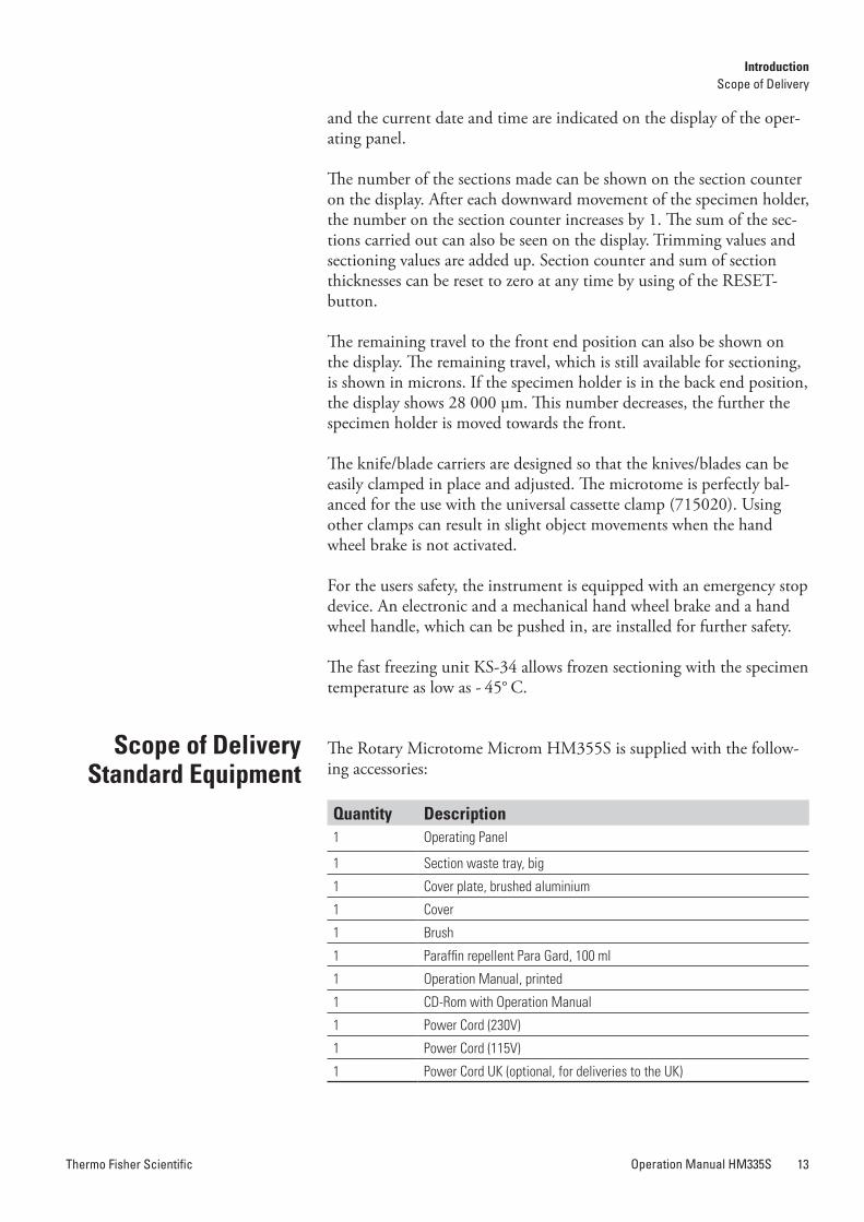
and the current date and time are indicated on the display of the oper-ating panel.
The number of the sections made can be shown on the section counter on the display. After each downward movement of the specimen holder, the number on the section counter increases by 1. The sum of the sec-tions carried out can also be seen on the display. Trimming values and sectioning values are added up. Section counter and sum of section thicknesses can be reset to zero at any time by using of the RESET-button.
The remaining travel to the front end position can also be shown on the display. The remaining travel, which is still available for sectioning, is shown in microns. If the specimen holder is in the back end position, the display shows 28 000 µm. This number decreases, the further the specimen holder is moved towards the front.
The knife/blade carriers are designed so that the knives/blades can be easily clamped in place and adjusted. The microtome is perfectly bal-anced for the use with the universal cassette clamp (715020). Using other clamps can result in slight object movements when the hand wheel brake is not activated.
For the users safety, the instrument is equipped with an emergency stop device. An electronic and a mechanical hand wheel brake and a hand wheel handle, which can be pushed in, are installed for further safety.
The fast freezing unit KS-34 allows frozen sectioning with the specimen temperature as low as - 45° C.
The Rotary Microtome Microm HM355S is supplied with the follow-ing accessories:
Quantity Description1 Operating Panel
1 Section waste tray, big
1 Cover plate, brushed aluminium
1 Cover
1 Brush
1 Paraffin repellent Para Gard, 100 ml
1 Operation Manual, printed
1 CD-Rom with Operation Manual
1 Power Cord (230V)
1 Power Cord (115V)
1 Power Cord UK (optional, for deliveries to the UK)
Description rotary Microtome hM355S
Scope of DeliveryStandard Equipment
IntroductionDescription HM355S
IntroductionScope of Delivery
Thermo Fisher ScientificOperation Manual HM335S12 Thermo Fisher Scientific Operation Manual HM335S 13
Chapter 2Introduction
The Thermo Scientific Rotary Microtome Microm HM355S is a uni-versal heavy duty microtome for specially designed for sophisticated paraffin and hard sectioning techniques in biology, medicine, industry and research.
The HM355S sets new ergonomical standards concerning operation and comfort. The instrument is equipped with a section waste tray with integrated arm rest. The waste tray is built around and under the knife/blade carrier for direct collection of section waste.
This model can be equipped with all compatible specimen clamps, knife and blade holders (see Additional Equipment) of the Rotary Microtome series. In addition, the stereomicroscope or the large field magnifier can be adapted.
The HM355S will cut sections in a range from 0,5 µm up to 100 µm. For the protection of knife and specimen, the instrument retracts the specimen at the end of the cut. If desired, the function <retraction> can be turned off. A trimming function with defined steps from 5 µm to 500 µm permits the fine adjustment up to the first cuts and results in larger section thicknesses when trimming.
The manual rotary movement of the hand wheel of the HM355S is converted into a vertical movement of the specimen clamping system. Sectioning is carried out by knives or blades, which must be adjusted and fixed on the knife/blade carrier.
The electronically controlled motor drive with precision tachometer generator guarantees an extremely fast adjustment to section force varia-tions and constant cutting speed. It also ensures optimal section quality in each field of application.
The motorized coarse feed system allows the continuous specimen for-ward and backward travel with variable speed settings. This way, speci-men and knife/blade edge distance can be adjusted quickly.
The operating panel is placed on the left side of the microtome. It can be removed and used separately, also on the right side of the instrument. To do this, the operating knobs can be removed and installed on the other side of the operating panel. The touchpad keyboard is clearly ar-ranged for easy and safe operation.
The selected section thickness, trimming thickness, section counter, sum of section thicknesses and remaining travel to the front end position as well as speed of the cutting movement, the operating mode
and the current date and time are indicated on the display of the oper-ating panel.
The number of the sections made can be shown on the section counter on the display. After each downward movement of the specimen holder, the number on the section counter increases by 1. The sum of the sec-tions carried out can also be seen on the display. Trimming values and sectioning values are added up. Section counter and sum of section thicknesses can be reset to zero at any time by using of the RESET-button.
The remaining travel to the front end position can also be shown on the display. The remaining travel, which is still available for sectioning, is shown in microns. If the specimen holder is in the back end position, the display shows 28 000 µm. This number decreases, the further the specimen holder is moved towards the front.
The knife/blade carriers are designed so that the knives/blades can be easily clamped in place and adjusted. The microtome is perfectly bal-anced for the use with the universal cassette clamp (715020). Using other clamps can result in slight object movements when the hand wheel brake is not activated.
For the users safety, the instrument is equipped with an emergency stop device. An electronic and a mechanical hand wheel brake and a hand wheel handle, which can be pushed in, are installed for further safety.
The fast freezing unit KS-34 allows frozen sectioning with the specimen temperature as low as - 45° C.
The Rotary Microtome Microm HM355S is supplied with the follow-ing accessories:
Quantity Description1 Operating Panel
1 Section waste tray, big
1 Cover plate, brushed aluminium
1 Cover
1 Brush
1 Paraffin repellent Para Gard, 100 ml
1 Operation Manual, printed
1 CD-Rom with Operation Manual
1 Power Cord (230V)
1 Power Cord (115V)
1 Power Cord UK (optional, for deliveries to the UK)
Description rotary Microtome hM355S
Scope of DeliveryStandard Equipment
IntroductionDescription HM355S
IntroductionScope of Delivery
Thermo Fisher ScientificOperation Manual HM335S14 Thermo Fisher Scientific Operation Manual HM335S 15
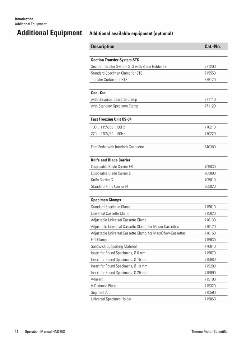
additional available equipment (optional)
Description Cat.-no.
Section Transfer System STS
Section Transfer System STS with Blade Holder TE 771200
Standard Specimen Clamp for STS 715550
Transfer Surface for STS 575170
Cool-Cut
with Universal Cassette Clamp 771110
with Standard Specimen Clamp 771120
Fast Freezing unit KS-34
100…115V/50…60Hz 770210
220…240V/50…60Hz 770220
Foot Pedal with Interlock Connector 640380
Knife and Blade Carrier
Disposable Blade Carrier ER 705830
Disposable Blade Carrier E 705800
Knife Carrier C 705810
Standard Knife Carrier N 705820
Specimen Clamps
Standard Specimen Clamp 715010
Universal Cassette Clamp 715020
Adjustable Universal Cassette Clamp 716130
Adjustable Universal Cassette Clamp, for Macro-Cassettes 716120
Adjustable Universal Cassette Clamp, for MacrOflow-Cassettes 716150
Foil Clamp 715030
Sandwich Supporting Material 176010
Insert for Round Specimens, Ø 6 mm 715070
Insert for Round Specimens, Ø 15 mm 715080
Insert for Round Specimens, Ø 19 mm 715280
Insert for Round Specimens, Ø 25 mm 715090
V-Insert 715100
V-Distance Piece 715320
Segment Arc 715590
Universal Specimen Holder 715060
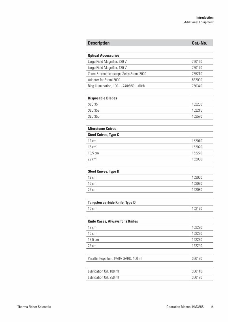
additional Equipment
Description Cat.-no.
Optical accessories
Large Field Magnifier, 220 V 760160
Large Field Magnifier, 120 V 760170
Zoom-Stereomicroscope Zeiss Stemi 2000 755210
Adapter for Stemi 2000 532090
Ring Illumination, 100….240V/50…60Hz 760340
Disposable Blades
SEC 35 152200
SEC 35e 152215
SEC 35p 152570
Microtome Knives
Steel Knives, Type C
12 cm 152010
16 cm 152020
18,5 cm 152270
22 cm 152030
Steel Knives, Type D
12 cm 152060
16 cm 152070
22 cm 152080
Tungsten carbide Knife, Type D
16 cm 152120
Knife Cases, always for 2 Knifes
12 cm 152220
16 cm 152230
18,5 cm 152280
22 cm 152240
Paraffin Repellent, PARA GARD, 100 ml 350170
Lubrication Oil, 100 ml 350110
Lubrication Oil, 250 ml 350120
IntroductionAdditional Equipment
IntroductionAdditional Equipment
Thermo Fisher ScientificOperation Manual HM335S14 Thermo Fisher Scientific Operation Manual HM335S 15
additional available equipment (optional)
Description Cat.-no.
Section Transfer System STS
Section Transfer System STS with Blade Holder TE 771200
Standard Specimen Clamp for STS 715550
Transfer Surface for STS 575170
Cool-Cut
with Universal Cassette Clamp 771110
with Standard Specimen Clamp 771120
Fast Freezing unit KS-34
100…115V/50…60Hz 770210
220…240V/50…60Hz 770220
Foot Pedal with Interlock Connector 640380
Knife and Blade Carrier
Disposable Blade Carrier ER 705830
Disposable Blade Carrier E 705800
Knife Carrier C 705810
Standard Knife Carrier N 705820
Specimen Clamps
Standard Specimen Clamp 715010
Universal Cassette Clamp 715020
Adjustable Universal Cassette Clamp 716130
Adjustable Universal Cassette Clamp, for Macro-Cassettes 716120
Adjustable Universal Cassette Clamp, for MacrOflow-Cassettes 716150
Foil Clamp 715030
Sandwich Supporting Material 176010
Insert for Round Specimens, Ø 6 mm 715070
Insert for Round Specimens, Ø 15 mm 715080
Insert for Round Specimens, Ø 19 mm 715280
Insert for Round Specimens, Ø 25 mm 715090
V-Insert 715100
V-Distance Piece 715320
Segment Arc 715590
Universal Specimen Holder 715060
additional Equipment
Description Cat.-no.
Optical accessories
Large Field Magnifier, 220 V 760160
Large Field Magnifier, 120 V 760170
Zoom-Stereomicroscope Zeiss Stemi 2000 755210
Adapter for Stemi 2000 532090
Ring Illumination, 100….240V/50…60Hz 760340
Disposable Blades
SEC 35 152200
SEC 35e 152215
SEC 35p 152570
Microtome Knives
Steel Knives, Type C
12 cm 152010
16 cm 152020
18,5 cm 152270
22 cm 152030
Steel Knives, Type D
12 cm 152060
16 cm 152070
22 cm 152080
Tungsten carbide Knife, Type D
16 cm 152120
Knife Cases, always for 2 Knifes
12 cm 152220
16 cm 152230
18,5 cm 152280
22 cm 152240
Paraffin Repellent, PARA GARD, 100 ml 350170
Lubrication Oil, 100 ml 350110
Lubrication Oil, 250 ml 350120
IntroductionAdditional Equipment
IntroductionAdditional Equipment
Thermo Fisher ScientificOperation Manual HM335S16 Thermo Fisher Scientific Operation Manual HM335S 17
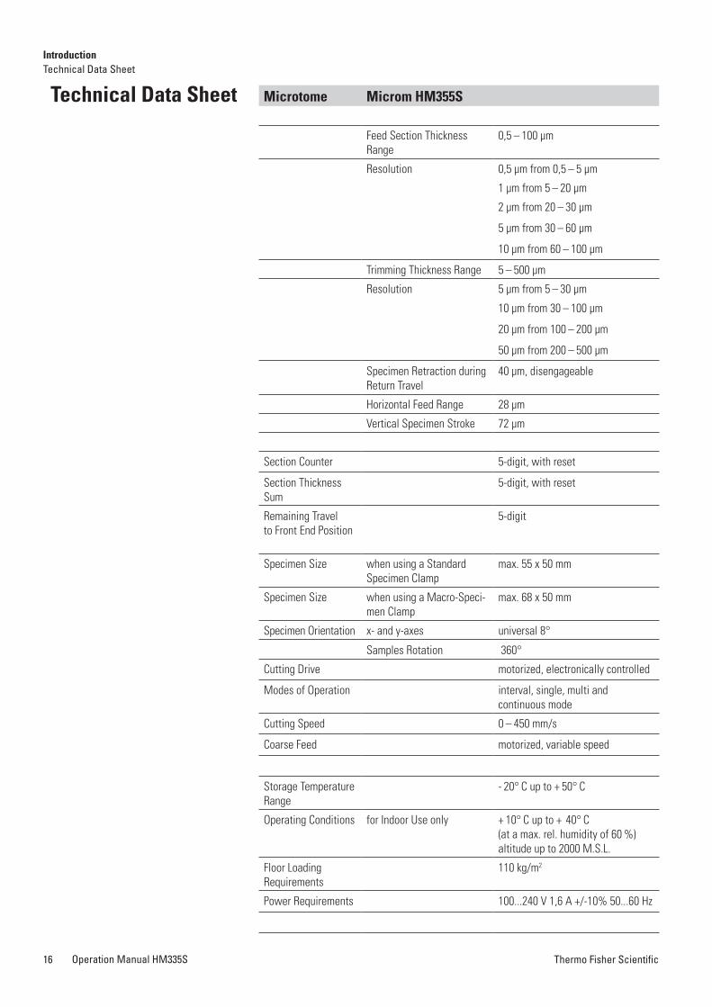
Microtome Microm hM355S
Feed Section Thickness Range
0,5 – 100 µm
Resolution 0,5 µm from 0,5 – 5 µm
1 µm from 5 – 20 µm
2 µm from 20 – 30 µm
5 µm from 30 – 60 µm
10 µm from 60 – 100 µm
Trimming Thickness Range 5 – 500 µm
Resolution 5 µm from 5 – 30 µm
10 µm from 30 – 100 µm
20 µm from 100 – 200 µm
50 µm from 200 – 500 µm
Specimen Retraction during Return Travel
40 µm, disengageable
Horizontal Feed Range 28 µm
Vertical Specimen Stroke 72 µm
Section Counter 5-digit, with reset
Section Thickness Sum
5-digit, with reset
Remaining Travelto Front End Position
5-digit
Specimen Size when using a Standard Specimen Clamp
max. 55 x 50 mm
Specimen Size when using a Macro-Speci-men Clamp
max. 68 x 50 mm
Specimen Orientation x- and y-axes universal 8°
Samples Rotation 360°
Cutting Drive motorized, electronically controlled
Modes of Operation interval, single, multi and continuous mode
Cutting Speed 0 – 450 mm/s
Coarse Feed motorized, variable speed
Storage Temperature Range
- 20° C up to + 50° C
Operating Conditions for Indoor Use only + 10° C up to + 40° C(at a max. rel. humidity of 60 %)altitude up to 2000 M.S.L.
Floor LoadingRequirements
110 kg/m2
Power Requirements 100...240 V 1,6 A +/-10% 50...60 Hz
Technical Data Sheet Microtome Microm hM355S
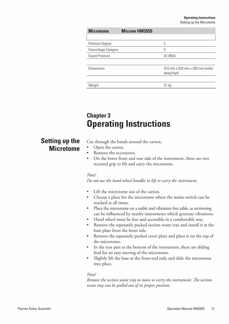
Pollution Degree 2
Overvoltage Category II
Sound Pressure 42 dB(A)
Dimensions 410 mm x 520 mm x 280 mm (wide/deep/high)
Weight 31 kg
Chapter 3Operating Instructions
Cut through the bands around the carton.• Open the carton.• Remove the accessories.• On the lower front and rear side of the instrument, there are two
recessed grip to lift and carry the microtome.
Note!Do not use the hand wheel handles to lift or carry the instrument.
• Lift the microtome out of the carton.• Choose a place for the microtome where the mains switch can be
reached at all times.• Place the microtome on a stable and vibration free table, as sectioning
can be influenced by nearby instruments which generate vibrations.• Hand wheel must be free and accessible in a comfortable way.• Remove the separately packed section waste tray and install it at the
base plate from the front side.• Remove the separately packed cover plate and place it on the top of
the microtome.• In the rear part at the bottom of the instrument, there are sliding
feed for an easy moving of the microtome.• Slightly lift the base at the front end only and slide the microtome
into place.
Note!Remove the section waste tray to move or carry the instrument. The section waste tray can be pulled out of its proper position.
Setting up theMicrotome
IntroductionTechnical Data Sheet
Operating InstructionsSetting up the Microtome
Thermo Fisher ScientificOperation Manual HM335S16 Thermo Fisher Scientific Operation Manual HM335S 17
Microtome Microm hM355S
Feed Section Thickness Range
0,5 – 100 µm
Resolution 0,5 µm from 0,5 – 5 µm
1 µm from 5 – 20 µm
2 µm from 20 – 30 µm
5 µm from 30 – 60 µm
10 µm from 60 – 100 µm
Trimming Thickness Range 5 – 500 µm
Resolution 5 µm from 5 – 30 µm
10 µm from 30 – 100 µm
20 µm from 100 – 200 µm
50 µm from 200 – 500 µm
Specimen Retraction during Return Travel
40 µm, disengageable
Horizontal Feed Range 28 µm
Vertical Specimen Stroke 72 µm
Section Counter 5-digit, with reset
Section Thickness Sum
5-digit, with reset
Remaining Travelto Front End Position
5-digit
Specimen Size when using a Standard Specimen Clamp
max. 55 x 50 mm
Specimen Size when using a Macro-Speci-men Clamp
max. 68 x 50 mm
Specimen Orientation x- and y-axes universal 8°
Samples Rotation 360°
Cutting Drive motorized, electronically controlled
Modes of Operation interval, single, multi and continuous mode
Cutting Speed 0 – 450 mm/s
Coarse Feed motorized, variable speed
Storage Temperature Range
- 20° C up to + 50° C
Operating Conditions for Indoor Use only + 10° C up to + 40° C(at a max. rel. humidity of 60 %)altitude up to 2000 M.S.L.
Floor LoadingRequirements
110 kg/m2
Power Requirements 100...240 V 1,6 A +/-10% 50...60 Hz
Technical Data Sheet Microtome Microm hM355S
Pollution Degree 2
Overvoltage Category II
Sound Pressure 42 dB(A)
Dimensions 410 mm x 520 mm x 280 mm (wide/deep/high)
Weight 31 kg
Chapter 3Operating Instructions
Cut through the bands around the carton.• Open the carton.• Remove the accessories.• On the lower front and rear side of the instrument, there are two
recessed grip to lift and carry the microtome.
Note!Do not use the hand wheel handles to lift or carry the instrument.
• Lift the microtome out of the carton.• Choose a place for the microtome where the mains switch can be
reached at all times.• Place the microtome on a stable and vibration free table, as sectioning
can be influenced by nearby instruments which generate vibrations.• Hand wheel must be free and accessible in a comfortable way.• Remove the separately packed section waste tray and install it at the
base plate from the front side.• Remove the separately packed cover plate and place it on the top of
the microtome.• In the rear part at the bottom of the instrument, there are sliding
feed for an easy moving of the microtome.• Slightly lift the base at the front end only and slide the microtome
into place.
Note!Remove the section waste tray to move or carry the instrument. The section waste tray can be pulled out of its proper position.
Setting up theMicrotome
IntroductionTechnical Data Sheet
Operating InstructionsSetting up the Microtome
Thermo Fisher ScientificOperation Manual HM335S18 Thermo Fisher Scientific Operation Manual HM335S 19
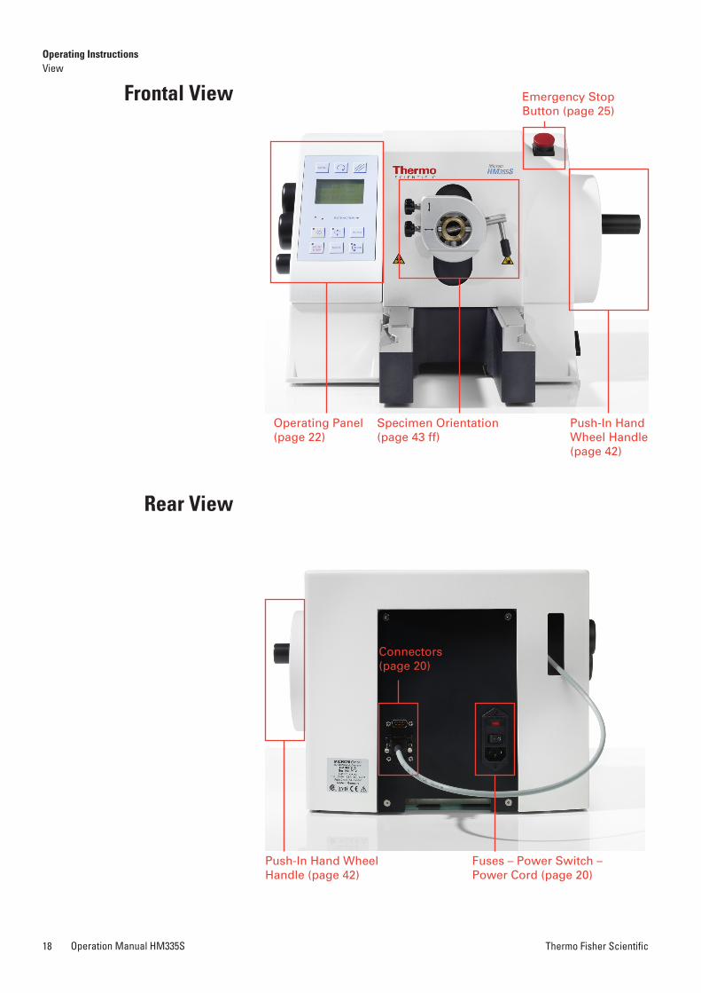
Frontal View
rear View
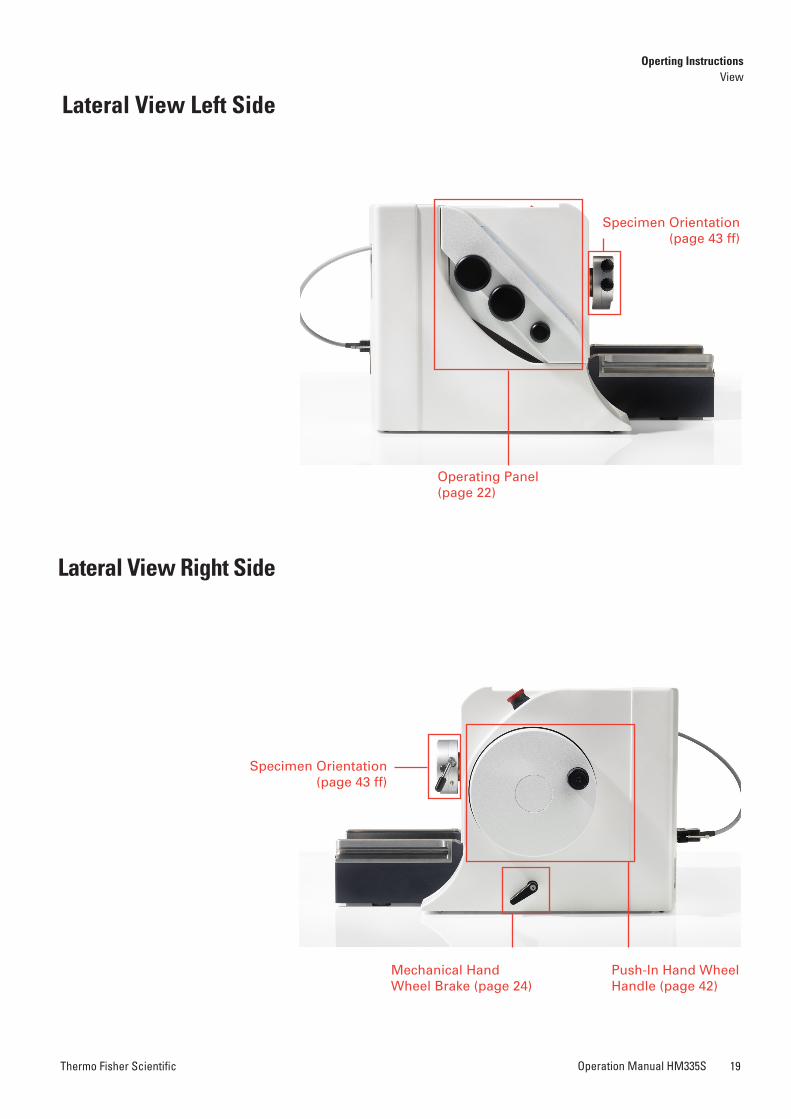
Lateral View Left Side
Lateral View right Side
Operating Panel (page 22)
Operating Panel (page 22)
Push-In Hand Wheel Handle (page 42)
Push-In Hand Wheel Handle (page 42)
Push-In Hand Wheel Handle (page 42)
Specimen Orientation (page 43 ff)
Emergency Stop Button (page 25)
Connectors (page 20)
Fuses – Power Switch – Power Cord (page 20)
Specimen Orientation (page 43 ff)
Operating InstructionsView
Operting InstructionsView
Mechanical Hand Wheel Brake (page 24)
Specimen Orientation (page 43 ff)
Thermo Fisher ScientificOperation Manual HM335S18 Thermo Fisher Scientific Operation Manual HM335S 19
Frontal View
rear View
Lateral View Left Side
Lateral View right Side
Operating Panel (page 22)
Operating Panel (page 22)
Push-In Hand Wheel Handle (page 42)
Push-In Hand Wheel Handle (page 42)
Push-In Hand Wheel Handle (page 42)
Specimen Orientation (page 43 ff)
Emergency Stop Button (page 25)
Connectors (page 20)
Fuses – Power Switch – Power Cord (page 20)
Specimen Orientation (page 43 ff)
Operating InstructionsView
Operting InstructionsView
Mechanical Hand Wheel Brake (page 24)
Specimen Orientation (page 43 ff)
Thermo Fisher ScientificOperation Manual HM335S20 Thermo Fisher Scientific Operation Manual HM335S 21
Note!A safe function of the Microtome is only ensured, if the equipment possesses a temperature within the specified operating conditions (see technical data sheet, page 14).We highly recommend that the Microtome rests at least 2 hours after unpacking at ambient temperature before switching it on for the first time.
Note!Before starting section, instrument, knife carrier and section waste tray should be treated with the included or any other commercially available paraffin repellent. This medium considerably reduces the adhesive property of paraffin sections to the individual parts (see page 13 and 15, standard and optional accessories)
Note!The type of examination materials used and all special conditions for their processing, pre-treatment and, if necessary, storage as well as instrument controls for correct and safe operation are the responsibility of the operator. The operator is also responsible for special equipment and materials and/or reagents used for the operation of the instrument.
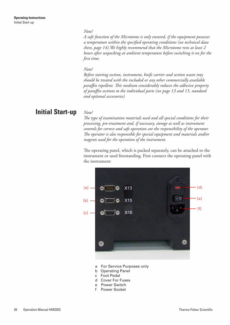
The operating panel, which is packed separately, can be attached to the instrument or used freestanding. First connect the operating panel with the instrument:
Initial Start-up
• Connect the cable of the operating panel to the connector (b) on the rear side of the microtome and fasten it with the two screws.
• Should the operating panel be attached to the instrument, push the con-nector through the corresponding hole on the rear side of the microtome.
• The operating panel can be used freestanding. It can be placed on the left as well as on the right side of the microtome.
• The knobs are separately packed and must be attached to the operating panel.
• The knobs can easily be removed and placed on the either side of the operating panel.
• Connect the plug of the foot pedal cable into the connector (c) and fasten the cable on the microtome with the two screws. (optional)
• Connector (a) is for service purposes only.
Note!(optional, for users of foot pedal only)If the foot pedal or interlock connector are not connected, the operating mode “emergency stop“ is used (page 25). In this mode, the electronic hand wheel brake is activated and the cutting drive motor cannot be started. Always connect the foot pedal or interlock connector!
Before using the Foot Pedal on HM355S first time (it applies to every HM355S using the foot pedal first time), you have to consider the following procedure:• Turn on the Microtome.• Connect the Dongle (Interlock connector) with connector X16 (c)
on the rear side of the microtome (see figure page 20).• Press the button on the Dongle in order to activate the “Emergency
Stop” function.• Now disconnect the Dongle. The “STOP” symbol should appear
on the display.• Connect the Foot Pedal with connector X16 (c).• Vigorously step on the foot pedal as far as it will go.• On display should appear the “STOP” Symbol as long as the foot
pedal is being stepped on. It shows that the “Emergency Stop” function is working properly.
Note!From now on always use either the Foot Pedal or the Dongle (without Foot Pedal); the instrument won’t work without them.
WARNING:The functionality of the built in emergency Stop function of the foot pedal has to be tested every time the foot pedal was newly connected with the micro-tome. The test has to be carried out before the microtome is used! After the foot pedal was connected with the microtome, press down the foot pedal complete-ly. “STOP” appears in the display, proven that the functionality is granted. The principle use of the Foot Pedal is written in the user manual of the microtome.
[a] [d]
[b] [e]
[c][f]
Operating InstructionsInitial Start-up
Operating InstructionsInitial Start-up
a For Service Purposes onlyb Operating Panelc Foot Pedald Cover For Fusese Power Switchf Power Socket
using the Foot Pedal (optional)
Thermo Fisher ScientificOperation Manual HM335S20 Thermo Fisher Scientific Operation Manual HM335S 21
Note!A safe function of the Microtome is only ensured, if the equipment possesses a temperature within the specified operating conditions (see technical data sheet, page 14).We highly recommend that the Microtome rests at least 2 hours after unpacking at ambient temperature before switching it on for the first time.
Note!Before starting section, instrument, knife carrier and section waste tray should be treated with the included or any other commercially available paraffin repellent. This medium considerably reduces the adhesive property of paraffin sections to the individual parts (see page 13 and 15, standard and optional accessories)
Note!The type of examination materials used and all special conditions for their processing, pre-treatment and, if necessary, storage as well as instrument controls for correct and safe operation are the responsibility of the operator. The operator is also responsible for special equipment and materials and/or reagents used for the operation of the instrument.
The operating panel, which is packed separately, can be attached to the instrument or used freestanding. First connect the operating panel with the instrument:
Initial Start-up
• Connect the cable of the operating panel to the connector (b) on the rear side of the microtome and fasten it with the two screws.
• Should the operating panel be attached to the instrument, push the con-nector through the corresponding hole on the rear side of the microtome.
• The operating panel can be used freestanding. It can be placed on the left as well as on the right side of the microtome.
• The knobs are separately packed and must be attached to the operating panel.
• The knobs can easily be removed and placed on the either side of the operating panel.
• Connect the plug of the foot pedal cable into the connector (c) and fasten the cable on the microtome with the two screws. (optional)
• Connector (a) is for service purposes only.
Note!(optional, for users of foot pedal only)If the foot pedal or interlock connector are not connected, the operating mode “emergency stop“ is used (page 25). In this mode, the electronic hand wheel brake is activated and the cutting drive motor cannot be started. Always connect the foot pedal or interlock connector!
Before using the Foot Pedal on HM355S first time (it applies to every HM355S using the foot pedal first time), you have to consider the following procedure:• Turn on the Microtome.• Connect the Dongle (Interlock connector) with connector X16 (c)
on the rear side of the microtome (see figure page 20).• Press the button on the Dongle in order to activate the “Emergency
Stop” function.• Now disconnect the Dongle. The “STOP” symbol should appear
on the display.• Connect the Foot Pedal with connector X16 (c).• Vigorously step on the foot pedal as far as it will go.• On display should appear the “STOP” Symbol as long as the foot
pedal is being stepped on. It shows that the “Emergency Stop” function is working properly.
Note!From now on always use either the Foot Pedal or the Dongle (without Foot Pedal); the instrument won’t work without them.
WARNING:The functionality of the built in emergency Stop function of the foot pedal has to be tested every time the foot pedal was newly connected with the micro-tome. The test has to be carried out before the microtome is used! After the foot pedal was connected with the microtome, press down the foot pedal complete-ly. “STOP” appears in the display, proven that the functionality is granted. The principle use of the Foot Pedal is written in the user manual of the microtome.
[a] [d]
[b] [e]
[c][f]
Operating InstructionsInitial Start-up
Operating InstructionsInitial Start-up
a For Service Purposes onlyb Operating Panelc Foot Pedald Cover For Fusese Power Switchf Power Socket
using the Foot Pedal (optional)
Thermo Fisher ScientificOperation Manual HM335S22 Thermo Fisher Scientific Operation Manual HM335S 23
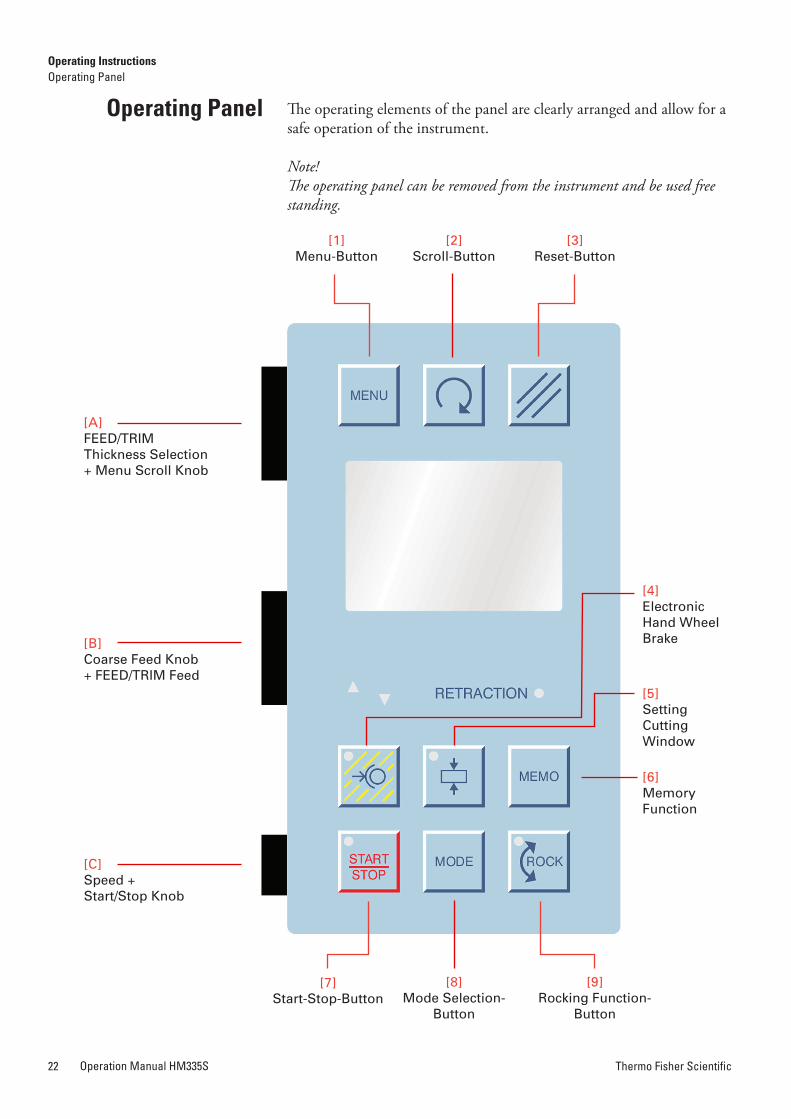
The operating elements of the panel are clearly arranged and allow for a safe operation of the instrument.
Note!The operating panel can be removed from the instrument and be used free standing.
Operating Panel Thermo Fisher Scientific Microtomes are designed to support your workflow.To achieve best results, take your time to get know the HM355S thoroughly before starting work.
• Turn the hand wheel so that the lower edge of the specimen is positioned slightly above the knife edge.
• Briefly press button [5] to set the upper limit of the cutting win-dow.
• Continue turning the hand wheel clockwise to place the upper edge of the specimen just below the knife edge.
• Briefly press button [5] again to set the lower limit of the cutting window.
A green LED in button [5] shows the length of the cutting window during each further passing through of the cutting window zone.
Note!A cutting window should only be set while the specimen is moved down-wards. If, by mistake, a cutting window limit is set during return travel of the specimen, the set limits are applied to the cutting movement accordingly.
The cutting drive can be turned on and off by pressing button [7] or knob [C] twice within 1 second or by pressing the foot pedal (optional) twice within 1 second.
Note!A double click is necessary in order to start the cutting drive.
For this, the function “emergency stop“ must not be activated and the mechanical brake must not be locked twice.
Note!The course function of the cutting drive results from the selected cutting window, the selected operating mode and the set cutting speed.
Caution!For your personal safety, push in the hand wheel handle before starting the motorized cutting drive.
Display and Key Functions
Setting Cutting Window
Starting and Stopping of Cutting Drive
[1]Menu-Button
[7]Start-Stop-Button
[2]Scroll-Button
[8]Mode Selection-
Button
[3]Reset-Button
[9]Rocking Function-
Button
[A]FEED/TRIMThickness Selection+ Menu Scroll Knob
[B]Coarse Feed Knob + FEED/TRIM Feed
[4]Electronic Hand Wheel Brake
[5]Setting CuttingWindow
[6]Memory Function
[C]Speed + Start/Stop Knob
Operating InstructionsOperating Panel
Operating InstructionsDisplay and Key Functions
Thermo Fisher ScientificOperation Manual HM335S22 Thermo Fisher Scientific Operation Manual HM335S 23
The operating elements of the panel are clearly arranged and allow for a safe operation of the instrument.
Note!The operating panel can be removed from the instrument and be used free standing.
Operating Panel Thermo Fisher Scientific Microtomes are designed to support your workflow.To achieve best results, take your time to get know the HM355S thoroughly before starting work.
• Turn the hand wheel so that the lower edge of the specimen is positioned slightly above the knife edge.
• Briefly press button [5] to set the upper limit of the cutting win-dow.
• Continue turning the hand wheel clockwise to place the upper edge of the specimen just below the knife edge.
• Briefly press button [5] again to set the lower limit of the cutting window.
A green LED in button [5] shows the length of the cutting window during each further passing through of the cutting window zone.
Note!A cutting window should only be set while the specimen is moved down-wards. If, by mistake, a cutting window limit is set during return travel of the specimen, the set limits are applied to the cutting movement accordingly.
The cutting drive can be turned on and off by pressing button [7] or knob [C] twice within 1 second or by pressing the foot pedal (optional) twice within 1 second.
Note!A double click is necessary in order to start the cutting drive.
For this, the function “emergency stop“ must not be activated and the mechanical brake must not be locked twice.
Note!The course function of the cutting drive results from the selected cutting window, the selected operating mode and the set cutting speed.
Caution!For your personal safety, push in the hand wheel handle before starting the motorized cutting drive.
Display and Key Functions
Setting Cutting Window
Starting and Stopping of Cutting Drive
[1]Menu-Button
[7]Start-Stop-Button
[2]Scroll-Button
[8]Mode Selection-
Button
[3]Reset-Button
[9]Rocking Function-
Button
[A]FEED/TRIMThickness Selection+ Menu Scroll Knob
[B]Coarse Feed Knob + FEED/TRIM Feed
[4]Electronic Hand Wheel Brake
[5]Setting CuttingWindow
[6]Memory Function
[C]Speed + Start/Stop Knob
Operating InstructionsOperating Panel
Operating InstructionsDisplay and Key Functions
Thermo Fisher ScientificOperation Manual HM335S24 Thermo Fisher Scientific Operation Manual HM335S 25
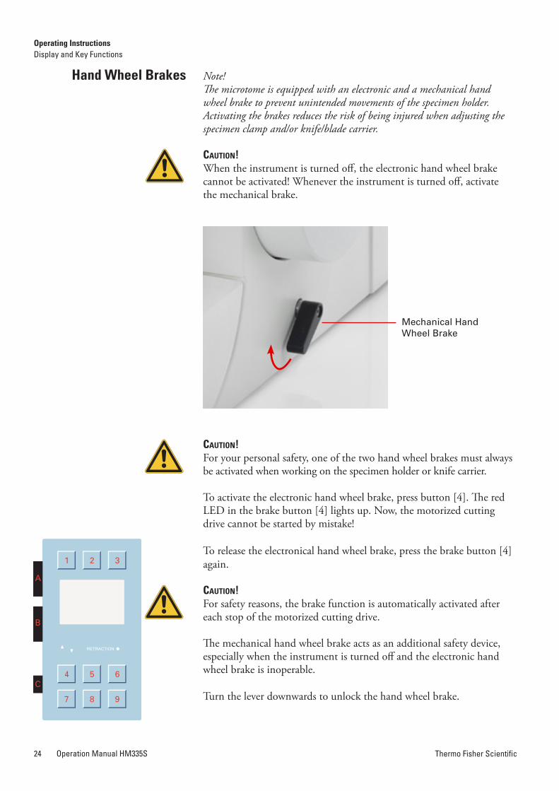
Note!The microtome is equipped with an electronic and a mechanical hand wheel brake to prevent unintended movements of the specimen holder. Activating the brakes reduces the risk of being injured when adjusting the specimen clamp and/or knife/blade carrier.
Caution!When the instrument is turned off, the electronic hand wheel brake cannot be activated! Whenever the instrument is turned off, activate the mechanical brake.
Caution!For your personal safety, one of the two hand wheel brakes must always be activated when working on the specimen holder or knife carrier.
To activate the electronic hand wheel brake, press button [4]. The red LED in the brake button [4] lights up. Now, the motorized cutting drive cannot be started by mistake!
To release the electronical hand wheel brake, press the brake button [4] again.
Caution!For safety reasons, the brake function is automatically activated after each stop of the motorized cutting drive.
The mechanical hand wheel brake acts as an additional safety device, especially when the instrument is turned off and the electronic hand wheel brake is inoperable.
Turn the lever downwards to unlock the hand wheel brake.
hand Wheel Brakes Pull the lever upwards in the direction of the arrow to lock the hand wheel. The STOP symbol appears in the display.
Note!Starting the cutting motor drive is not possible when the instrument is turned off or when the mechanical hand wheel brake is activated. This is indicated by a STOP symbol appears in the display. A red LED in the brake button lights up when the electronic brake is activated.
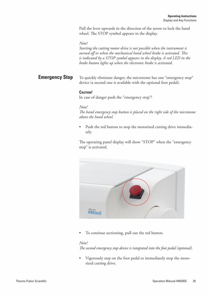
To quickly eliminate danger, the microtome has one “emergency stop“ device (a second one is available with the optional foot pedal).
Caution!In case of danger push the “emergency stop“!
Note!The hand emergency stop button is placed on the right side of the microtome above the hand wheel.
• Push the red button to stop the motorized cutting drive immedia-tely.
The operating panel display will show “STOP” when the “emergency stop” is activated.
• To continue sectioning, pull out the red button.
Note!The second emergency stop device is integrated into the foot pedal (optional).
• Vigorously step on the foot pedal to immediately stop the moto-rized cutting drive.
Mechanical Hand Wheel Brake
Emergency Stop
Operating InstructionsDisplay and Key Functions
Operating InstructionsDisplay and Key Functions
Thermo Fisher ScientificOperation Manual HM335S24 Thermo Fisher Scientific Operation Manual HM335S 25
Note!The microtome is equipped with an electronic and a mechanical hand wheel brake to prevent unintended movements of the specimen holder. Activating the brakes reduces the risk of being injured when adjusting the specimen clamp and/or knife/blade carrier.
Caution!When the instrument is turned off, the electronic hand wheel brake cannot be activated! Whenever the instrument is turned off, activate the mechanical brake.
Caution!For your personal safety, one of the two hand wheel brakes must always be activated when working on the specimen holder or knife carrier.
To activate the electronic hand wheel brake, press button [4]. The red LED in the brake button [4] lights up. Now, the motorized cutting drive cannot be started by mistake!
To release the electronical hand wheel brake, press the brake button [4] again.
Caution!For safety reasons, the brake function is automatically activated after each stop of the motorized cutting drive.
The mechanical hand wheel brake acts as an additional safety device, especially when the instrument is turned off and the electronic hand wheel brake is inoperable.
Turn the lever downwards to unlock the hand wheel brake.
hand Wheel Brakes Pull the lever upwards in the direction of the arrow to lock the hand wheel. The STOP symbol appears in the display.
Note!Starting the cutting motor drive is not possible when the instrument is turned off or when the mechanical hand wheel brake is activated. This is indicated by a STOP symbol appears in the display. A red LED in the brake button lights up when the electronic brake is activated.
To quickly eliminate danger, the microtome has one “emergency stop“ device (a second one is available with the optional foot pedal).
Caution!In case of danger push the “emergency stop“!
Note!The hand emergency stop button is placed on the right side of the microtome above the hand wheel.
• Push the red button to stop the motorized cutting drive immedia-tely.
The operating panel display will show “STOP” when the “emergency stop” is activated.
• To continue sectioning, pull out the red button.
Note!The second emergency stop device is integrated into the foot pedal (optional).
• Vigorously step on the foot pedal to immediately stop the moto-rized cutting drive.
Mechanical Hand Wheel Brake
Emergency Stop
Operating InstructionsDisplay and Key Functions
Operating InstructionsDisplay and Key Functions
Thermo Fisher ScientificOperation Manual HM335S26 Thermo Fisher Scientific Operation Manual HM335S 27
This emergency stop device is activated as long as the foot pedal is being stepped on. “STOP” is shown on the display of the operating panel, if the “emergency stop“ is activated.
• To continue sectioning, release the foot pedal. The cutting drive can be started again.
In the middle line of the display information about the sectioning status can be seen.
• Press the “scroll button“ [2], to show a list of the functions on the display.
The following information on the current sectioning position of the instrument can alternatively be seen in the middle line of the display: – number of sections
– sum of section thicknesses
– remaining travel to the front end position
• To do so, press button [2] until the required information is shown on the display.
If no information is required in this line, press button [2] until this line of the display is blank.
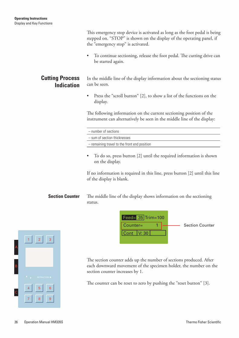
The middle line of the display shows information on the sectioning status.
The section counter adds up the number of sections produced. After each downward movement of the specimen holder, the number on the section counter increases by 1.
The counter can be reset to zero by pushing the “reset button“ [3].
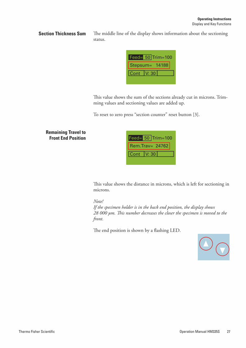
The middle line of the display shows information about the sectioning status.
This value shows the sum of the sections already cut in microns. Trim-ming values and sectioning values are added up.
To reset to zero press “section counter” reset button [3].
This value shows the distance in microns, which is left for sectioning in microns.
Note!If the specimen holder is in the back end position, the display shows 28 000 µm. This number decreases the closer the specimen is moved to the front.
The end position is shown by a flashing LED.
Cutting Process Indication
Section Counter
Section Counter
Section Thickness Sum
remaining Travel to Front End Position
Operating InstructionsDisplay and Key Functions
Operating InstructionsDisplay and Key Functions
Thermo Fisher ScientificOperation Manual HM335S26 Thermo Fisher Scientific Operation Manual HM335S 27
This emergency stop device is activated as long as the foot pedal is being stepped on. “STOP” is shown on the display of the operating panel, if the “emergency stop“ is activated.
• To continue sectioning, release the foot pedal. The cutting drive can be started again.
In the middle line of the display information about the sectioning status can be seen.
• Press the “scroll button“ [2], to show a list of the functions on the display.
The following information on the current sectioning position of the instrument can alternatively be seen in the middle line of the display: – number of sections
– sum of section thicknesses
– remaining travel to the front end position
• To do so, press button [2] until the required information is shown on the display.
If no information is required in this line, press button [2] until this line of the display is blank.
The middle line of the display shows information on the sectioning status.
The section counter adds up the number of sections produced. After each downward movement of the specimen holder, the number on the section counter increases by 1.
The counter can be reset to zero by pushing the “reset button“ [3].
The middle line of the display shows information about the sectioning status.
This value shows the sum of the sections already cut in microns. Trim-ming values and sectioning values are added up.
To reset to zero press “section counter” reset button [3].
This value shows the distance in microns, which is left for sectioning in microns.
Note!If the specimen holder is in the back end position, the display shows 28 000 µm. This number decreases the closer the specimen is moved to the front.
The end position is shown by a flashing LED.
Cutting Process Indication
Section Counter
Section Counter
Section Thickness Sum
remaining Travel to Front End Position
Operating InstructionsDisplay and Key Functions
Operating InstructionsDisplay and Key Functions
Thermo Fisher ScientificOperation Manual HM335S28 Thermo Fisher Scientific Operation Manual HM335S 29
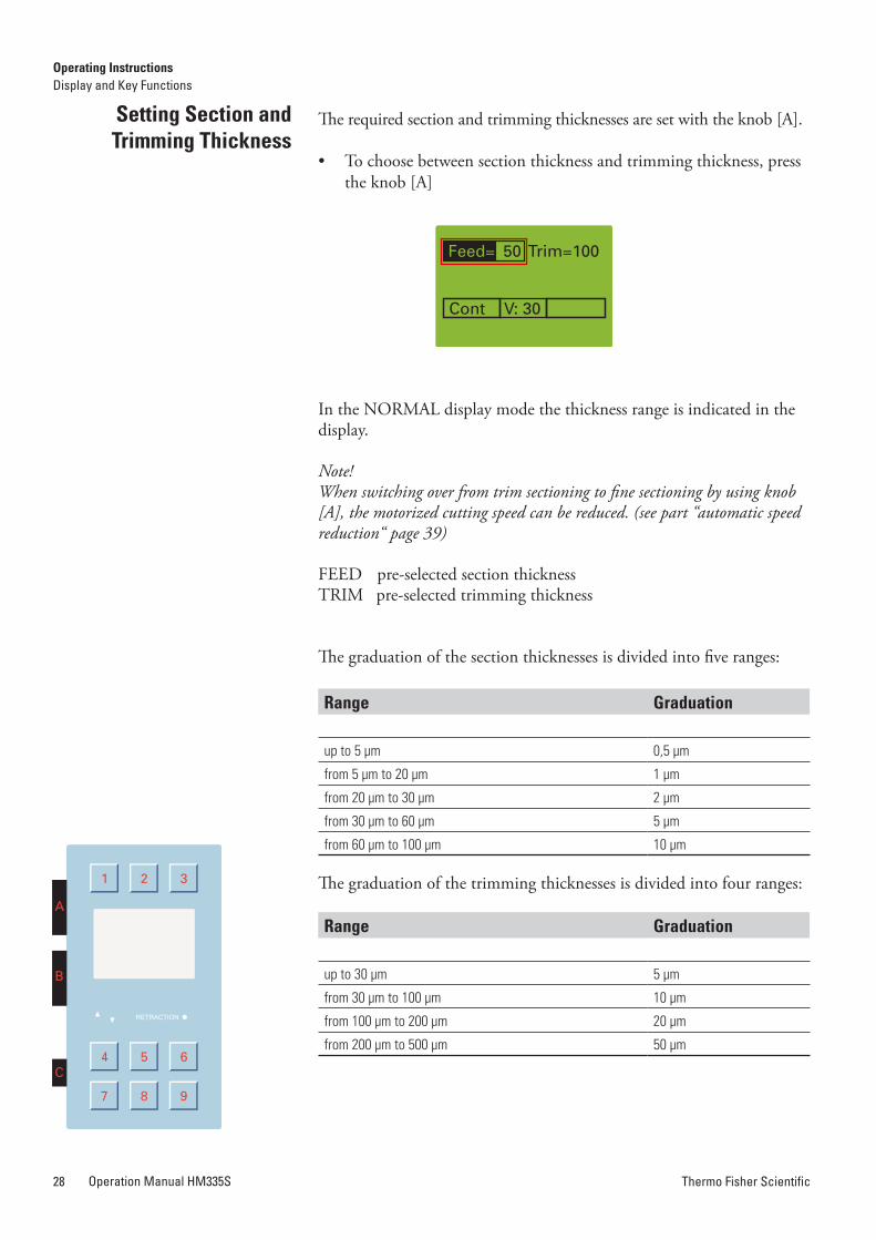
The required section and trimming thicknesses are set with the knob [A].
• To choose between section thickness and trimming thickness, press the knob [A]
In the NORMAL display mode the thickness range is indicated in the display.
Note!When switching over from trim sectioning to fine sectioning by using knob [A], the motorized cutting speed can be reduced. (see part “automatic speed reduction“ page 39)
FEED pre-selected section thicknessTRIM pre-selected trimming thickness
Setting Section and Trimming Thickness
The graduation of the section thicknesses is divided into five ranges:
range graduation
up to 5 µm 0,5 µm
from 5 µm to 20 µm 1 µm
from 20 µm to 30 µm 2 µm
from 30 µm to 60 µm 5 µm
from 60 µm to 100 µm 10 µm
The graduation of the trimming thicknesses is divided into four ranges:
range graduation
up to 30 µm 5 µm
from 30 µm to 100 µm 10 µm
from 100 µm to 200 µm 20 µm
from 200 µm to 500 µm 50 µm
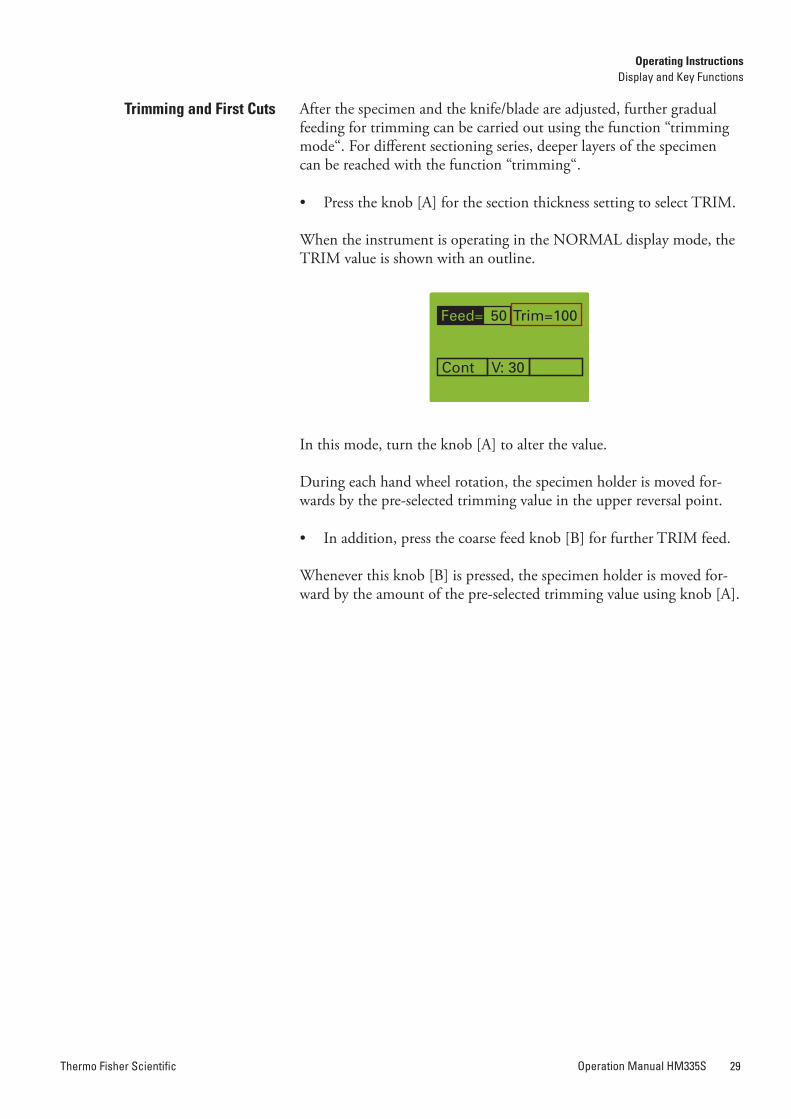
After the specimen and the knife/blade are adjusted, further gradual feeding for trimming can be carried out using the function “trimming mode“. For different sectioning series, deeper layers of the specimen can be reached with the function “trimming“.
• Press the knob [A] for the section thickness setting to select TRIM.
When the instrument is operating in the NORMAL display mode, the TRIM value is shown with an outline.
In this mode, turn the knob [A] to alter the value.
During each hand wheel rotation, the specimen holder is moved for-wards by the pre-selected trimming value in the upper reversal point.
• In addition, press the coarse feed knob [B] for further TRIM feed.
Whenever this knob [B] is pressed, the specimen holder is moved for-ward by the amount of the pre-selected trimming value using knob [A].
Trimming and First Cuts
Operating InstructionsDisplay and Key Functions
Operating InstructionsDisplay and Key Functions
Thermo Fisher ScientificOperation Manual HM335S28 Thermo Fisher Scientific Operation Manual HM335S 29
The required section and trimming thicknesses are set with the knob [A].
• To choose between section thickness and trimming thickness, press the knob [A]
In the NORMAL display mode the thickness range is indicated in the display.
Note!When switching over from trim sectioning to fine sectioning by using knob [A], the motorized cutting speed can be reduced. (see part “automatic speed reduction“ page 39)
FEED pre-selected section thicknessTRIM pre-selected trimming thickness
Setting Section and Trimming Thickness
The graduation of the section thicknesses is divided into five ranges:
range graduation
up to 5 µm 0,5 µm
from 5 µm to 20 µm 1 µm
from 20 µm to 30 µm 2 µm
from 30 µm to 60 µm 5 µm
from 60 µm to 100 µm 10 µm
The graduation of the trimming thicknesses is divided into four ranges:
range graduation
up to 30 µm 5 µm
from 30 µm to 100 µm 10 µm
from 100 µm to 200 µm 20 µm
from 200 µm to 500 µm 50 µm
After the specimen and the knife/blade are adjusted, further gradual feeding for trimming can be carried out using the function “trimming mode“. For different sectioning series, deeper layers of the specimen can be reached with the function “trimming“.
• Press the knob [A] for the section thickness setting to select TRIM.
When the instrument is operating in the NORMAL display mode, the TRIM value is shown with an outline.
In this mode, turn the knob [A] to alter the value.
During each hand wheel rotation, the specimen holder is moved for-wards by the pre-selected trimming value in the upper reversal point.
• In addition, press the coarse feed knob [B] for further TRIM feed.
Whenever this knob [B] is pressed, the specimen holder is moved for-ward by the amount of the pre-selected trimming value using knob [A].
Trimming and First Cuts
Operating InstructionsDisplay and Key Functions
Operating InstructionsDisplay and Key Functions
Thermo Fisher ScientificOperation Manual HM335S30 Thermo Fisher Scientific Operation Manual HM335S 31
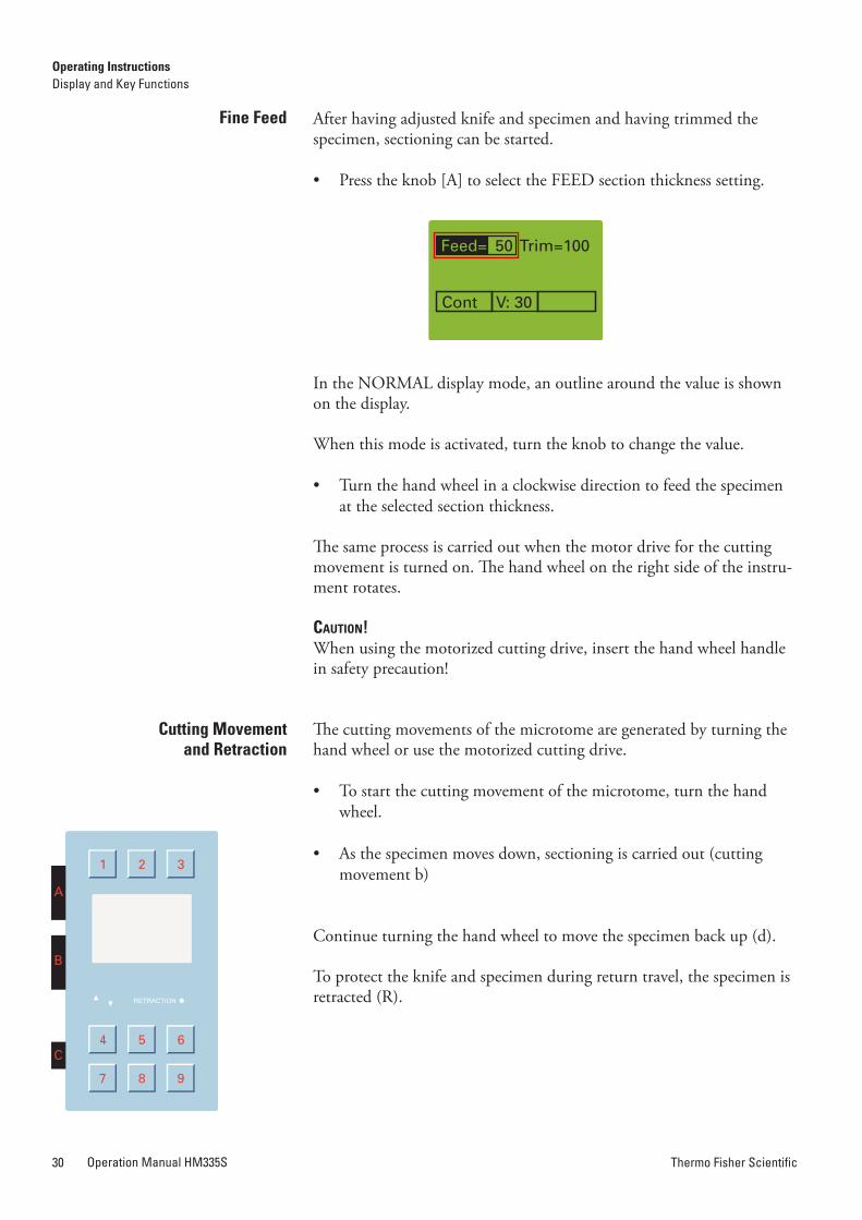
Fine Feed After having adjusted knife and specimen and having trimmed the specimen, sectioning can be started.
• Press the knob [A] to select the FEED section thickness setting.
In the NORMAL display mode, an outline around the value is shown on the display.
When this mode is activated, turn the knob to change the value.
• Turn the hand wheel in a clockwise direction to feed the specimen at the selected section thickness.
The same process is carried out when the motor drive for the cutting movement is turned on. The hand wheel on the right side of the instru-ment rotates.
Caution!When using the motorized cutting drive, insert the hand wheel handle in safety precaution!
The cutting movements of the microtome are generated by turning the hand wheel or use the motorized cutting drive.
• To start the cutting movement of the microtome, turn the hand wheel.
• As the specimen moves down, sectioning is carried out (cutting movement b)
Continue turning the hand wheel to move the specimen back up (d).
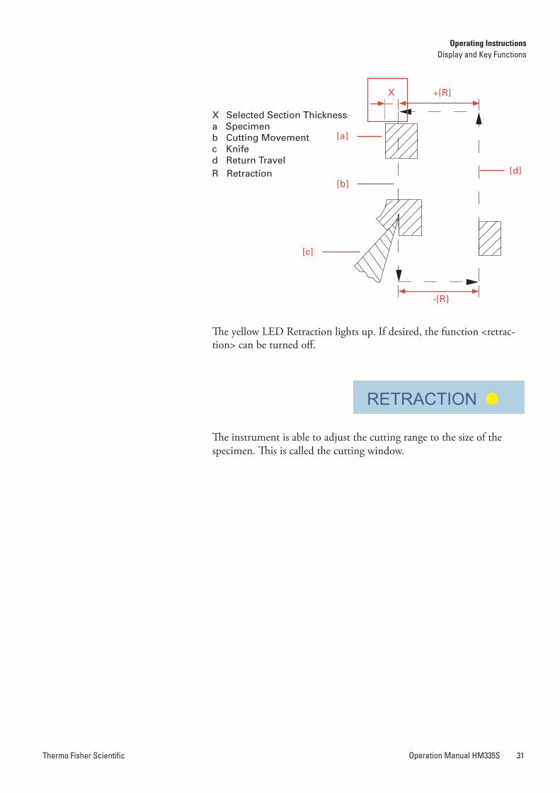
To protect the knife and specimen during return travel, the specimen is retracted (R).
Cutting Movement and retraction
X Selected Section Thickness a Specimen b Cutting Movement c Knifed Return TravelR Retraction
The yellow LED Retraction lights up. If desired, the function <retrac-tion> can be turned off.
The instrument is able to adjust the cutting range to the size of the specimen. This is called the cutting window.
[a]
[b]
[c]
[d]
+[R]X
-[R]
Operating InstructionsDisplay and Key Functions
Operating InstructionsDisplay and Key Functions
Thermo Fisher ScientificOperation Manual HM335S30 Thermo Fisher Scientific Operation Manual HM335S 31
Fine Feed After having adjusted knife and specimen and having trimmed the specimen, sectioning can be started.
• Press the knob [A] to select the FEED section thickness setting.
In the NORMAL display mode, an outline around the value is shown on the display.
When this mode is activated, turn the knob to change the value.
• Turn the hand wheel in a clockwise direction to feed the specimen at the selected section thickness.
The same process is carried out when the motor drive for the cutting movement is turned on. The hand wheel on the right side of the instru-ment rotates.
Caution!When using the motorized cutting drive, insert the hand wheel handle in safety precaution!
The cutting movements of the microtome are generated by turning the hand wheel or use the motorized cutting drive.
• To start the cutting movement of the microtome, turn the hand wheel.
• As the specimen moves down, sectioning is carried out (cutting movement b)
Continue turning the hand wheel to move the specimen back up (d).
To protect the knife and specimen during return travel, the specimen is retracted (R).
Cutting Movement and retraction
X Selected Section Thickness a Specimen b Cutting Movement c Knifed Return TravelR Retraction
The yellow LED Retraction lights up. If desired, the function <retrac-tion> can be turned off.
The instrument is able to adjust the cutting range to the size of the specimen. This is called the cutting window.
[a]
[b]
[c]
[d]
+[R]X
-[R]
Operating InstructionsDisplay and Key Functions
Operating InstructionsDisplay and Key Functions
Thermo Fisher ScientificOperation Manual HM335S32 Thermo Fisher Scientific Operation Manual HM335S 33
Automatic return movement can be stopped by briefly turning knob [B] in the opposite direction.
The coarse feed motor turns off after having reached the back end position.
Cutting movements can either be started by pressing the button START/STOP twice, by stepping on the foot pedal (optional), or by pressing knob [C].
When the specimen orientation is in the front end position, the red LED arrow (pointing downward) on the operating panel lights up.
When the specimen orientation is in the back end position, the red LED arrow (showing upward) on the operating panel lights up.
Press the knob [B] to release trim feed with the selected value, even if the fine mode is active.
For the motorized cutting movement of the microtome, the following operating modes are available:
– interval stroke
– single stroke
– multi stroke
– continuous stroke
The operating mode can be selected in two ways:
• directly with the MODE-button [8]• over Menu by using knob [A]
• Press the MODE-button [8] gradually to change among the 4 dif-ferent operating modes
Note!When selecting multi stroke via the MODE-button [8], the default value of sections is 2. To change this default value, please see page 35.
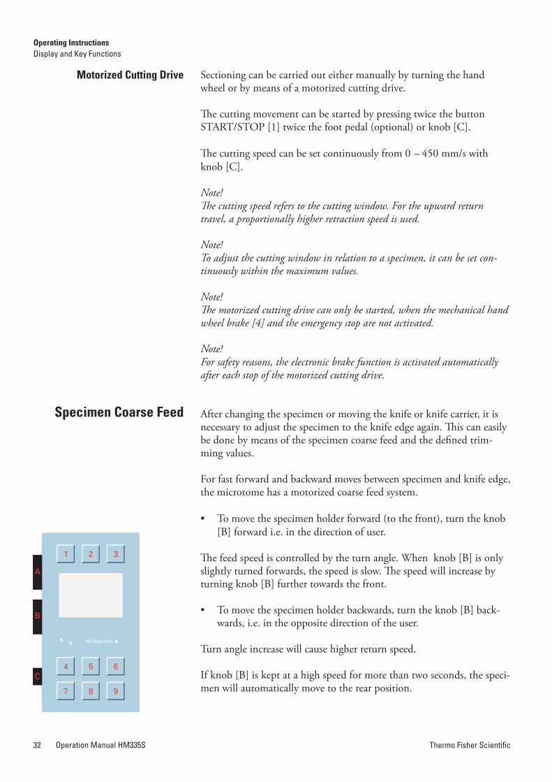
Motorized Cutting Drive Sectioning can be carried out either manually by turning the hand wheel or by means of a motorized cutting drive.
The cutting movement can be started by pressing twice the button START/STOP [1] twice the foot pedal (optional) or knob [C].
The cutting speed can be set continuously from 0 – 450 mm/s with knob [C].
Note!The cutting speed refers to the cutting window. For the upward return travel, a proportionally higher retraction speed is used.
Note!To adjust the cutting window in relation to a specimen, it can be set con-tinuously within the maximum values.
Note!The motorized cutting drive can only be started, when the mechanical hand wheel brake [4] and the emergency stop are not activated.
Note!For safety reasons, the electronic brake function is activated automatically after each stop of the motorized cutting drive.
After changing the specimen or moving the knife or knife carrier, it is necessary to adjust the specimen to the knife edge again. This can easily be done by means of the specimen coarse feed and the defined trim-ming values.
For fast forward and backward moves between specimen and knife edge, the microtome has a motorized coarse feed system.
• To move the specimen holder forward (to the front), turn the knob [B] forward i.e. in the direction of user.
The feed speed is controlled by the turn angle. When knob [B] is only slightly turned forwards, the speed is slow. The speed will increase by turning knob [B] fur ther towards the front.
• To move the specimen holder backwards, turn the knob [B] back-wards, i.e. in the opposite direction of the user.
Turn angle increase will cause higher return speed.
If knob [B] is kept at a high speed for more than two seconds, the speci-men will automatically move to the rear position.
Specimen Coarse Feed
Operating Modes
Operating InstructionsDisplay and Key Functions
Operating InstructionsDisplay and Key Functions
Selection of Operating Modes
Mode Selection viaMODE-Button
Thermo Fisher ScientificOperation Manual HM335S32 Thermo Fisher Scientific Operation Manual HM335S 33
Automatic return movement can be stopped by briefly turning knob [B] in the opposite direction.
The coarse feed motor turns off after having reached the back end position.
Cutting movements can either be started by pressing the button START/STOP twice, by stepping on the foot pedal (optional), or by pressing knob [C].
When the specimen orientation is in the front end position, the red LED arrow (pointing downward) on the operating panel lights up.
When the specimen orientation is in the back end position, the red LED arrow (showing upward) on the operating panel lights up.
Press the knob [B] to release trim feed with the selected value, even if the fine mode is active.
For the motorized cutting movement of the microtome, the following operating modes are available:
– interval stroke
– single stroke
– multi stroke
– continuous stroke
The operating mode can be selected in two ways:
• directly with the MODE-button [8]• over Menu by using knob [A]
• Press the MODE-button [8] gradually to change among the 4 dif-ferent operating modes
Note!When selecting multi stroke via the MODE-button [8], the default value of sections is 2. To change this default value, please see page 35.
Motorized Cutting Drive Sectioning can be carried out either manually by turning the hand wheel or by means of a motorized cutting drive.
The cutting movement can be started by pressing twice the button START/STOP [1] twice the foot pedal (optional) or knob [C].
The cutting speed can be set continuously from 0 – 450 mm/s with knob [C].
Note!The cutting speed refers to the cutting window. For the upward return travel, a proportionally higher retraction speed is used.
Note!To adjust the cutting window in relation to a specimen, it can be set con-tinuously within the maximum values.
Note!The motorized cutting drive can only be started, when the mechanical hand wheel brake [4] and the emergency stop are not activated.
Note!For safety reasons, the electronic brake function is activated automatically after each stop of the motorized cutting drive.
After changing the specimen or moving the knife or knife carrier, it is necessary to adjust the specimen to the knife edge again. This can easily be done by means of the specimen coarse feed and the defined trim-ming values.
For fast forward and backward moves between specimen and knife edge, the microtome has a motorized coarse feed system.
• To move the specimen holder forward (to the front), turn the knob [B] forward i.e. in the direction of user.
The feed speed is controlled by the turn angle. When knob [B] is only slightly turned forwards, the speed is slow. The speed will increase by turning knob [B] fur ther towards the front.
• To move the specimen holder backwards, turn the knob [B] back-wards, i.e. in the opposite direction of the user.
Turn angle increase will cause higher return speed.
If knob [B] is kept at a high speed for more than two seconds, the speci-men will automatically move to the rear position.
Specimen Coarse Feed
Operating Modes
Operating InstructionsDisplay and Key Functions
Operating InstructionsDisplay and Key Functions
Selection of Operating Modes
Mode Selection viaMODE-Button
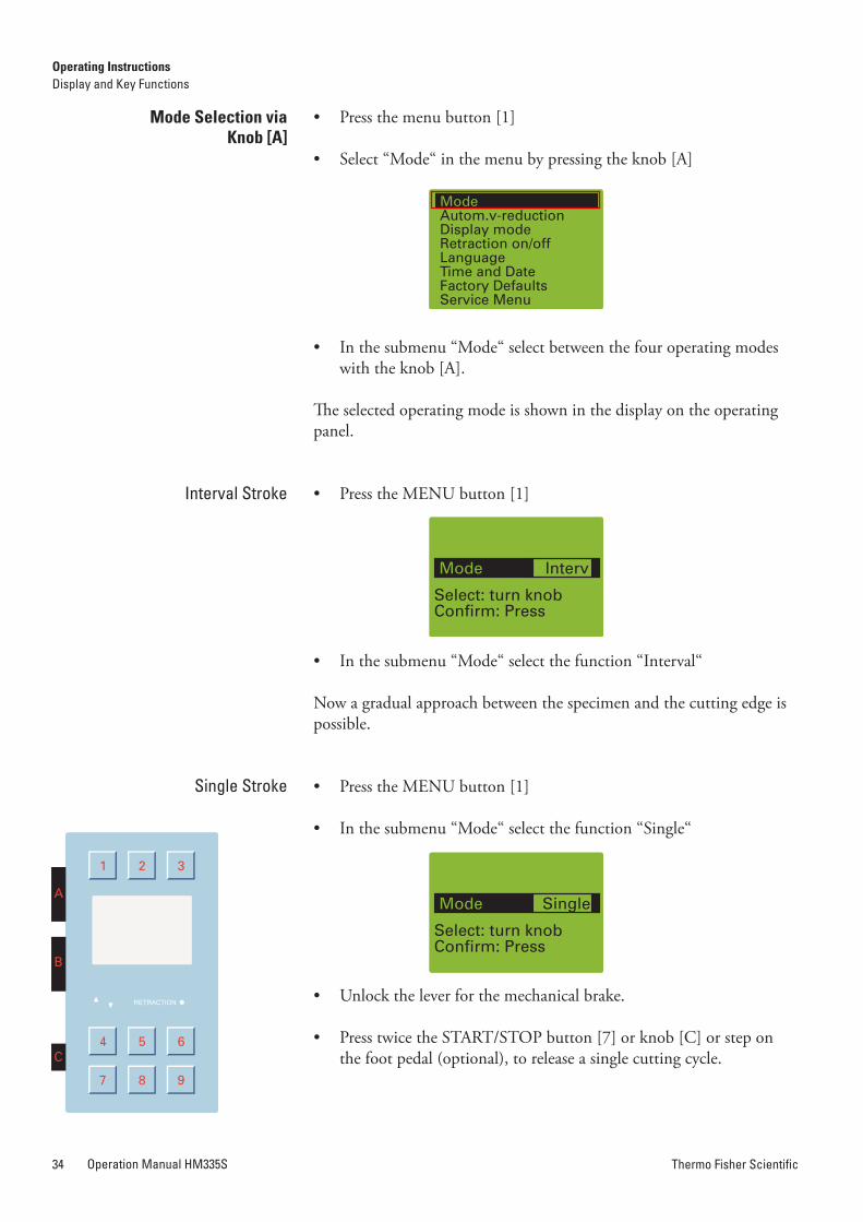
Thermo Fisher ScientificOperation Manual HM335S34 Thermo Fisher Scientific Operation Manual HM335S 35
• Press the menu button [1]
• Select “Mode“ in the menu by pressing the knob [A]
• In the submenu “Mode“ select between the four operating modes with the knob [A].
The selected operating mode is shown in the display on the operating panel.
• Press the MENU button [1]
• In the submenu “Mode“ select the function “Interval“
Now a gradual approach between the specimen and the cutting edge is possible.
• Press the MENU button [1]
• In the submenu “Mode“ select the function “Single“
• Unlock the lever for the mechanical brake.
• Press twice the START/STOP button [7] or knob [C] or step on the foot pedal (optional), to release a single cutting cycle.
• Press the MENU button [1].
• Select the function “Multi“ in the submenu “Mode“ by turning the knob [C] and confirm by pressing it.
• Then press the knob [C] again.
• Then turn it to select the desired number of sections. The number of the cutting strokes depends on the chosen pre-selection (2 up to 99).
• Unlock the lever for mechanical stroke.
• Press twice the START/STOP button [7] or the knob [C] or the foot pedal (optional), to release a multiple cutting cycle.
After the set number of sections has been carried out, the movement stops in the upper reversal point.
• Press the MENU button [1].
• In the submenu “Mode“ select the function “Cont“ via the knob [A]or button [8].
• Unlock the lever for the mechanical brake
• To start a continuous cutting cycle, press twice the START/STOP button or knob [C] or step on the foot pedal (optional).
To stop the continuous stroke, press knob [C] or the brake button [4] or the foot pedal (optional) once more.
Note!If a cutting cycle has been started, it will run through to the end and stop in the next upper reversal point.
Mode Selection viaKnob [a]
Interval Stroke
Single Stroke
Multi Stroke
Continuous Stroke
Operating InstructionsDisplay and Key Functions
Operating InstructionsDisplay and Key Functions
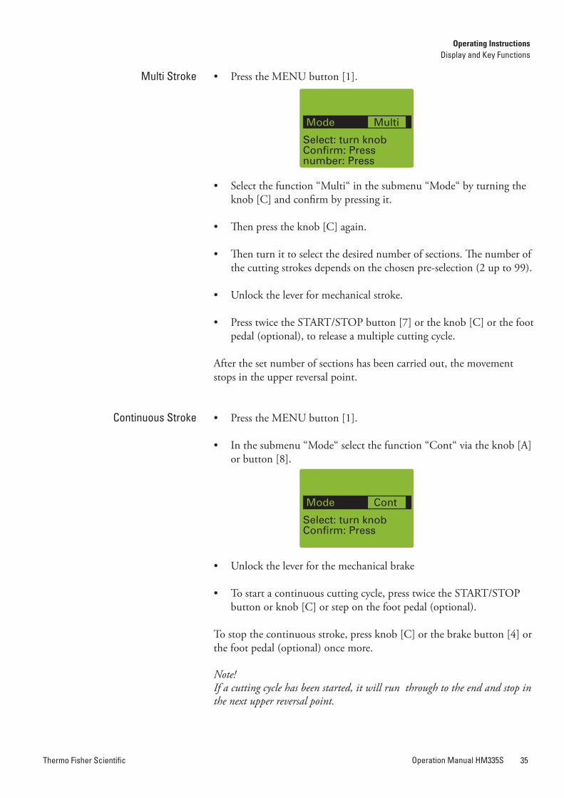
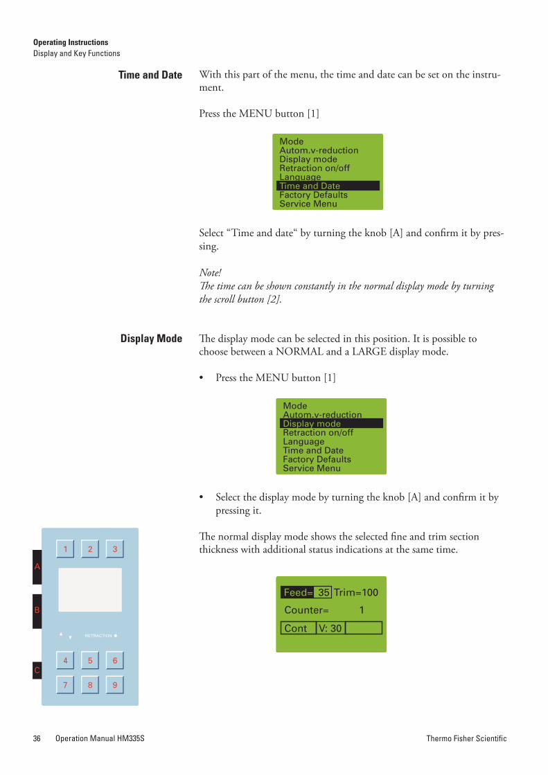
Thermo Fisher ScientificOperation Manual HM335S36 Thermo Fisher Scientific Operation Manual HM335S 37
With this part of the menu, the time and date can be set on the instru-ment.
Press the MENU button [1]
Select “Time and date“ by turning the knob [A] and confirm it by pres-sing.
Note!The time can be shown constantly in the normal display mode by turning the scroll button [2].
The display mode can be selected in this position. It is possible to choose between a NORMAL and a LARGE display mode.
• Press the MENU button [1]
• Select the display mode by turning the knob [A] and confirm it by pressing it.
The normal display mode shows the selected fine and trim section thickness with additional status indications at the same time.
Time and Date
Turning off the “retraction” Function
If desired, the function “Retraction“ can be turned off.
• Press the MENU button [1]
• Select submenu “Retraction“ by turning the knob [A].
• Press the knob to confirm the selection.
• Turn the knob [A] to select the desired function: ON or OFF
• Press the knob [A] to confirm the setting.
The yellow LED RETRACTION might stay on and will go off only after the specimen has been passed through the cutting movement by turning hand wheel.
• To turn the „Retraction“ mode on again, please proceed as descri-bed above.
Note!The selected function is shown on the display as ON or OFF.
Display Mode
Large Display Mode
Operating InstructionsDisplay and Key Functions
Operating InstructionsDisplay and Key Functions
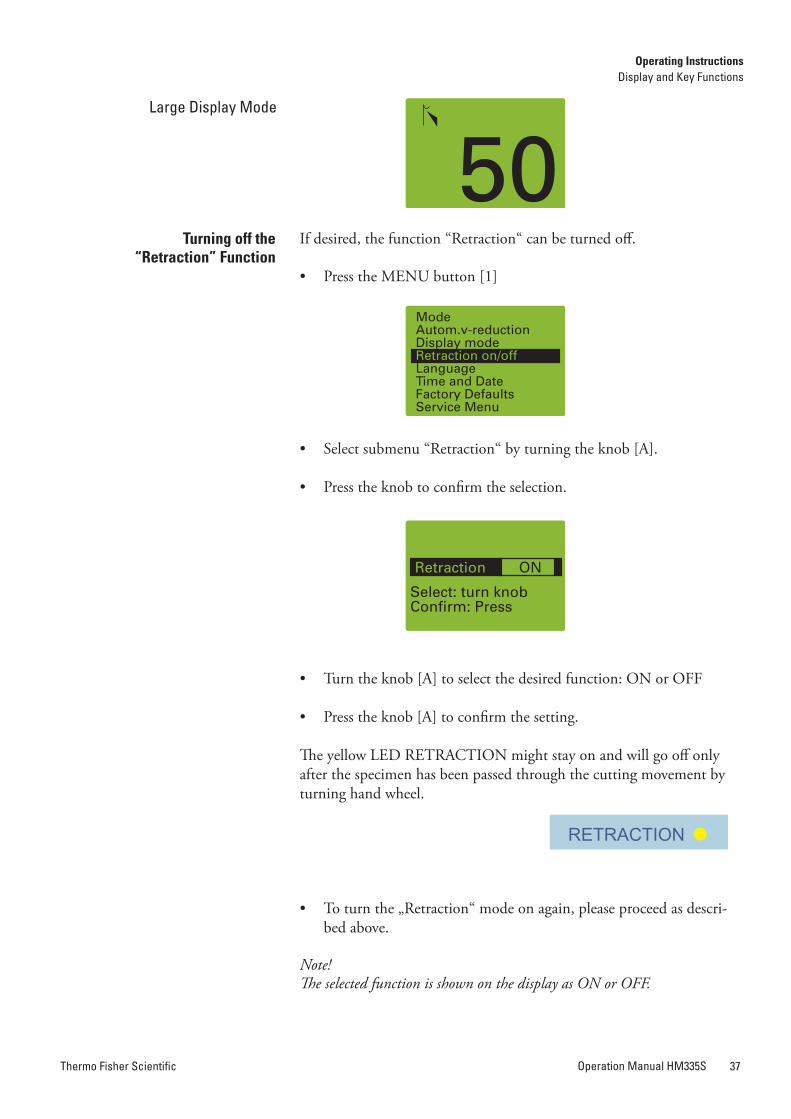

Thermo Fisher ScientificOperation Manual HM335S38 Thermo Fisher Scientific Operation Manual HM335S 39
• The desired cutting speed is set continuously with the knob [C] and is shown on display with values from 0–100.
Note!To save time, the return travel speed is faster than the selected cutting speed.
In addition, the maximum cutting speed can be turned slower for fine sectioning than for trim sectioning.
Switching over from trim sectioning to fine sectioning with knob [A] results in a reduction of the motorized cutting speed according to the corresponding pre-selection.
• To pre-select the speed reduction, press the menu button [1]
• In the sub-menu select „Autom. v-reduction“ with the knob [A]
• Turn the knob [A] to select the maximum speed from 0 up to 100.
• Press the knob [A] again to store the selected speed.
• Press the menu button [1] again to return to the normal display mode.
Caution!Switching over from fine sectioning to trim sectioning results in a corre-sponding speed increase.
Setting the Cutting Speed
The information on the display can be shown in different languages.
– German
– English
– French
– Spanish
– Italian
• Press the MENU button [1]
• In the sub-menu select „Languages“ by turning the knob [A]
• Turn the knob [A] to select the desired language.
• Press the knob [A] to confirm the selected language.
• Press the menu button [1] to return to the NORMAL display mode.
The display now shows the information in the desired language.
Language Selection for the Display
Operating InstructionsDisplay and Key Functions
Operating InstructionsDisplay and Key Functions
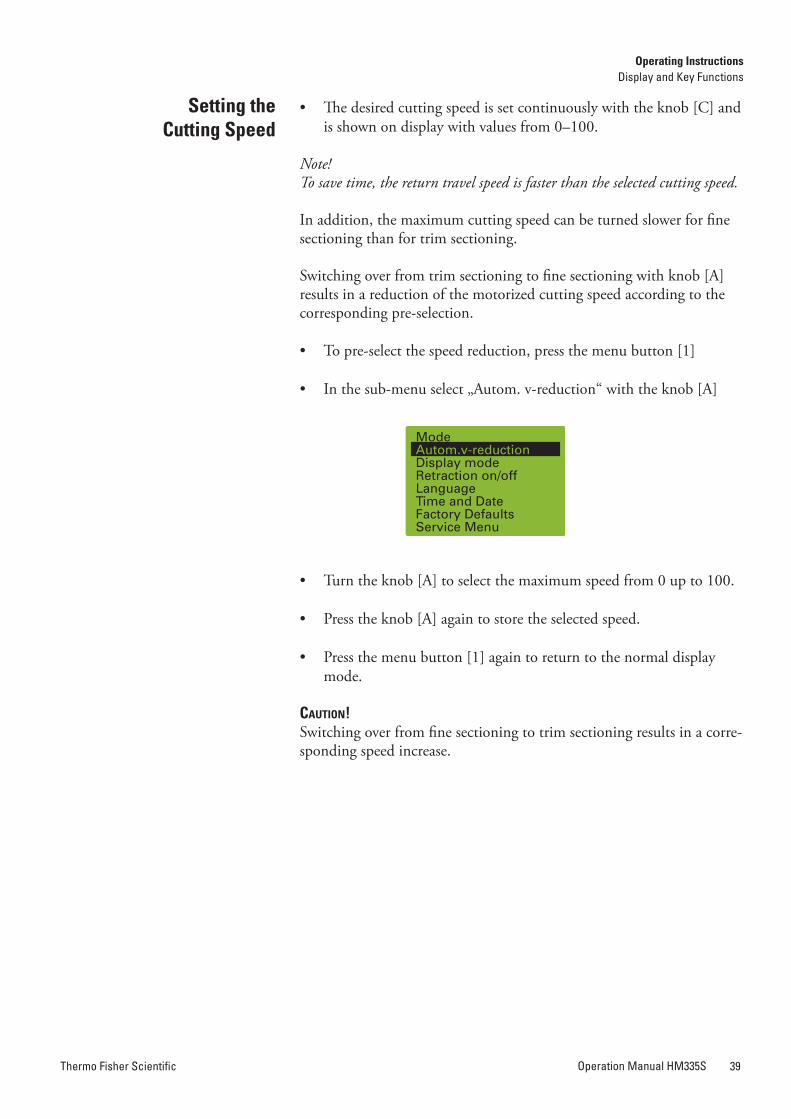
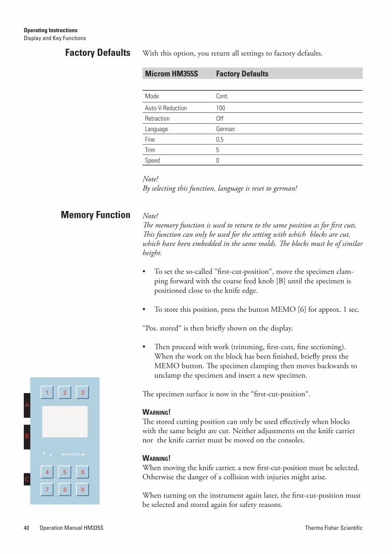
Thermo Fisher ScientificOperation Manual HM335S40 Thermo Fisher Scientific Operation Manual HM335S 41
With this option, you return all settings to factory defaults.
Microm hM355S Factory Defaults
Mode Cont.
Auto-V-Reduction 100
Retraction Off
Language German
Fine 0,5
Trim 5
Speed 0
Note!By selecting this function, language is reset to german!
Note!The memory function is used to return to the same position as for first cuts. This function can only be used for the setting with which blocks are cut, which have been embedded in the same molds. The blocks must be of similar height.
• To set the so-called “first-cut-position“, move the specimen clam-ping forward with the coarse feed knob [B] until the specimen is positioned close to the knife edge.
• To store this position, press the button MEMO [6] for approx. 1 sec.
“Pos. stored“ is then briefly shown on the display.
• Then proceed with work (trimming, first-cuts, fine sectioning). When the work on the block has been finished, briefly press the MEMO button. The specimen clamping then moves backwards to unclamp the specimen and insert a new specimen.
The specimen surface is now in the “first-cut-position“.
Warning!The stored cutting position can only be used effectively when blocks with the same height are cut. Neither adjustments on the knife carrier nor the knife carrier must be moved on the consoles.
Warning!When moving the knife carrier, a new first-cut-position must be selected. Otherwise the danger of a collision with injuries might arise.
When turning on the instrument again later, the first-cut-position must be selected and stored again for safety reasons.
Factory Defaults
Memory Function
Newly installed, allows you to perform manual sectioning in rocking mode. To cut the sample, you just move the hand wheel up and down.
• Press the ROCK button [9] to start Rocking function.
• Press the ROCK button [9] again to turn it off.
rocking Mode Function
Setting the rocking Function
Operating InstructionsDisplay and Key Functions
Operating InstructionsDisplay and Key Functions
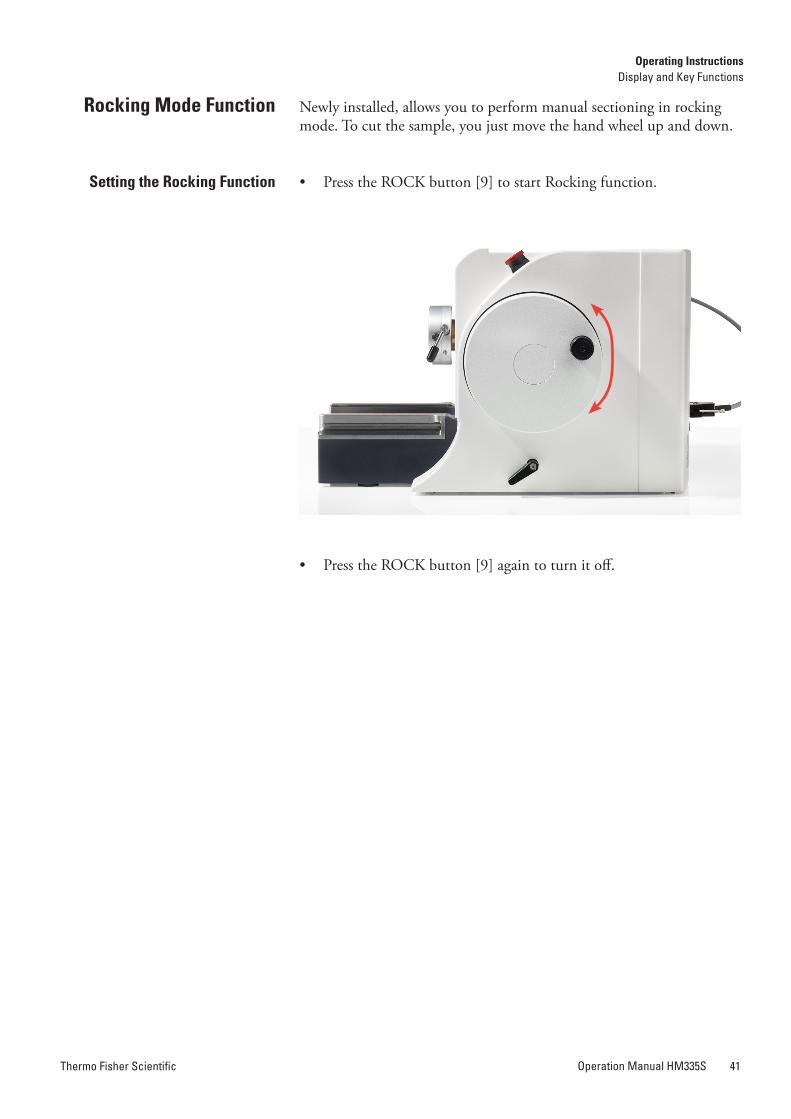
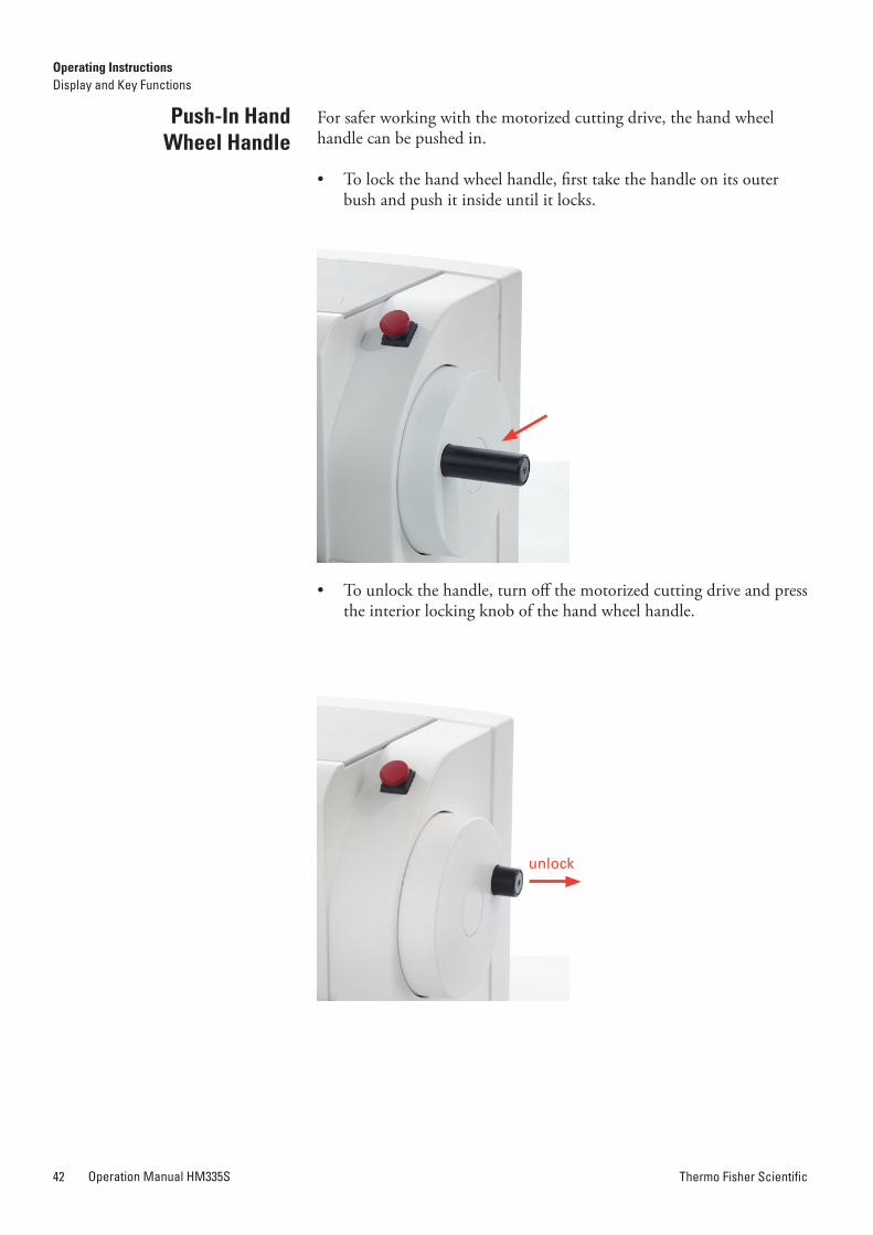
Thermo Fisher ScientificOperation Manual HM335S42 Thermo Fisher Scientific Operation Manual HM335S 43
For safer working with the motorized cutting drive, the hand wheel handle can be pushed in.
• To lock the hand wheel handle, first take the handle on its outer bush and push it inside until it locks.
• To unlock the handle, turn off the motorized cutting drive and press the interior locking knob of the hand wheel handle.
Push-In hand Wheel handle
This adapter serves for a non-orienting fastening of the specimen clamps directly onto the cylinder of the instrument.
This adapter serves for an orienting fastening of the specimen clamps. This allows the specimen to be aligned with the knife/blade.
To bring the specimen into the desired position, move the clamping lever [a] towards the front.
This will loosen the specimen clamp and a rotation of 360° on the cylinder axis (Z-axis) is possible.
With the two orienting screws [b], the specimen clamp can be moved 8° in each direction on the X-axis and Y-axis.
After having oriented the specimen, turn the lever [a] upwards to fix the specimen clamp in its position before starting sectioning.
Note!When turning the orienting screws [b] a slight resistance can be felt when the clamp is aligned parallel with the cutting surface.
adapters for Specimen Clamping
adapter, non-orienting
adapter, orienting, Specimen Orientation
[a]
[b]
Operating InstructionsDisplay and Key Functions
Operating InstructionsAdapters for Specimen Clamping
unlock
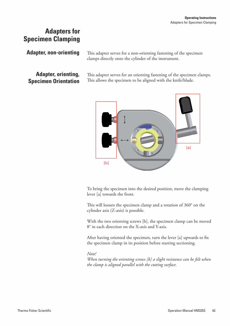
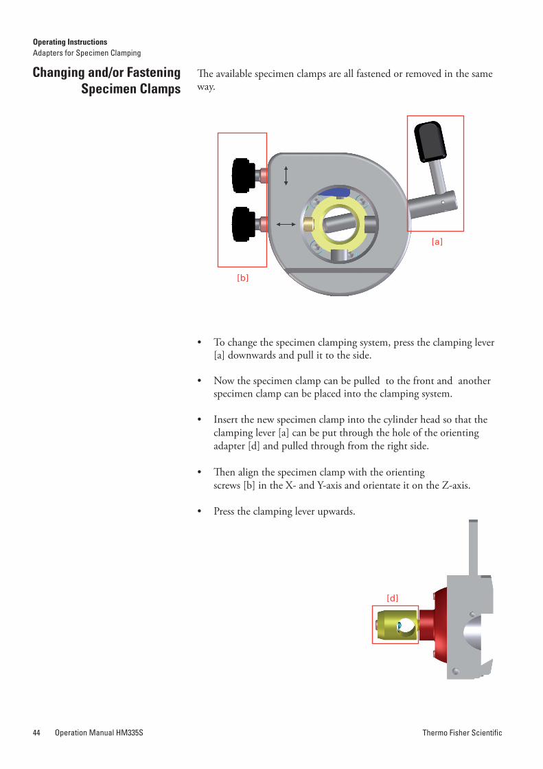
Thermo Fisher ScientificOperation Manual HM335S44 Thermo Fisher Scientific Operation Manual HM335S 45
The available specimen clamps are all fastened or removed in the same way.
• To change the specimen clamping system, press the clamping lever [a] downwards and pull it to the side.
• Now the specimen clamp can be pulled to the front and another specimen clamp can be placed into the clamping system.
• Insert the new specimen clamp into the cylinder head so that the clamping lever [a] can be put through the hole of the orienting adapter [d] and pulled through from the right side.
• Then align the specimen clamp with the orienting screws [b] in the X- and Y-axis and orientate it on the Z-axis.
• Press the clamping lever upwards.
Changing and/or Fastening Specimen Clamps
[a]
[b]
Note!Frequent use of the clamping lever can result in loss of optimal clamping strength. If the necessary readjustment is not carried out, it might be pos-sible that the specimen clamp does not clamp anymore.
The clamping lever [a] should be in an almost upright position.
• To determine the clamping position of the clamping lever [a], ad-just the inner screw [c] on the backside of the orienting adapter [d] using an allen key (size 3 mm).
• Turn the allen key in a clockwise direction if no clamping is possible or if the position of the clamping lever [a] is too high.
• If the clamping position of the clamping lever [a] is too low, turn the allen key in a counter-clockwise direction.
re-adjusting Specimen Clamps
[c]
Operating InstructionsAdapters for Specimen Clamping
Operating InstructionsAdapters for Specimen Clamping
[d]
[d]
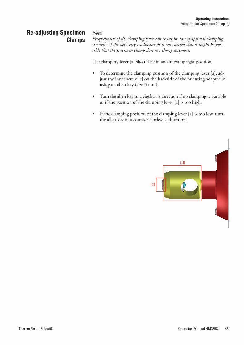
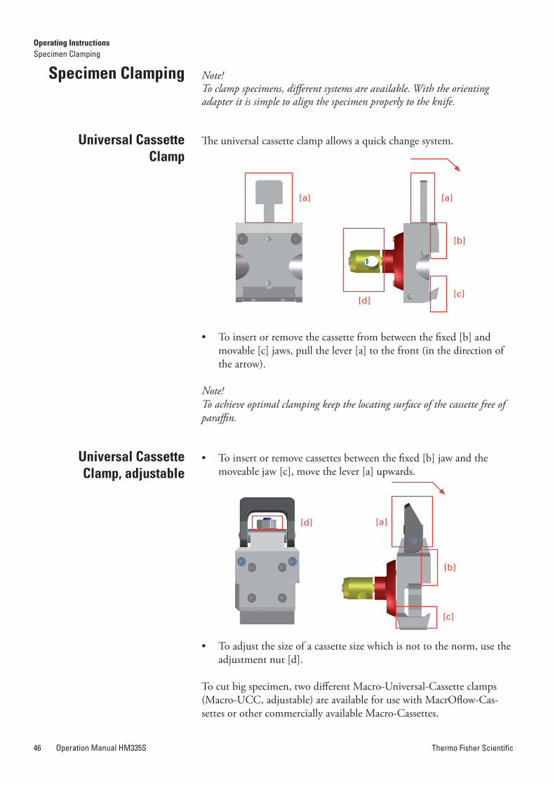
Thermo Fisher ScientificOperation Manual HM335S46 Thermo Fisher Scientific Operation Manual HM335S 47
Note!To clamp specimens, different systems are available. With the orienting adapter it is simple to align the specimen properly to the knife.
The universal cassette clamp allows a quick change system.
• To insert or remove the cassette from between the fixed [b] and movable [c] jaws, pull the lever [a] to the front (in the direction of the arrow).
Note!To achieve optimal clamping keep the locating surface of the cassette free of paraffin.
• To insert or remove cassettes between the fixed [b] jaw and the moveable jaw [c], move the lever [a] upwards.
• To adjust the size of a cassette size which is not to the norm, use the adjustment nut [d].
To cut big specimen, two different Macro-Universal-Cassette clamps (Macro-UCC, adjustable) are available for use with MacrOflow-Cas-settes or other commercially available Macro-Cassettes.
Specimen Clamping
universal Cassette Clamp
universal Cassette Clamp, adjustable
The unrestricted use of the Macro-UCC is only possible with ER blade carrier.
Note!Maximum 68mm x 50mm specimen size can be cut. The Paraffin blocks in MacrOflow-Cassettes are 70-72mm long and should be trimmed to 68mm length manually.
The standard specimen clamp is used for rectangular and square paraf-fin and plastic blocks.
• Insert the specimen against the fixed jaw [b] first.
• Then tighten with the clamping screw [a] to tighten the specimen via the movable jaw [c].
Note!For the stability of the specimen, do not let it project too much over the clamping jaws.
Note!The standard specimen clamp is equipped with two different movable jaws [c], which are of different weight. The lightweight jaw is used with inserts for round specimens.
Standard Specimen Clamp
[a]
[b]
[c]
[a]
[a]
[c]
[d]
[b]
Operating InstructionsSpecimen Clamping
Operating InstructionsSpecimen Clamping
[b]
[c]
[a]
[a] [a]
[b]
[c][d]
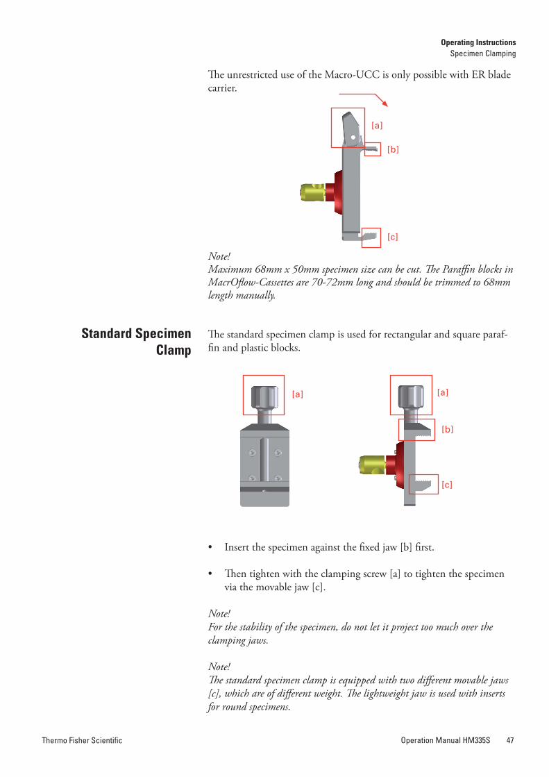
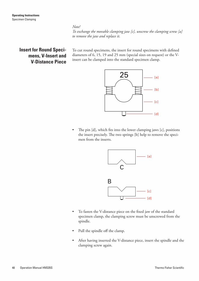
Thermo Fisher ScientificOperation Manual HM335S48 Thermo Fisher Scientific Operation Manual HM335S 49
Note!To exchange the movable clamping jaw [c], unscrew the clamping screw [a] to remove the jaw and replace it.
To cut round specimens, the insert for round specimens with defined diameters of 6, 15, 19 and 25 mm (special sizes on request) or the V-insert can be clamped into the standard specimen clamp.
• The pin [d], which fits into the lower clamping jaws [c], positions the insert precisely. The two springs [b] help to remove the speci-men from the inserts.
• To fasten the V-distance piece on the fixed jaw of the standard specimen clamp, the clamping screw must be unscrewed from the spindle.
• Pull the spindle off the clamp.
• After having inserted the V-distance piece, insert the spindle and the clamping screw again.
Insert for round Speci-mens, V-Insert and
V-Distance Piece
25 [a]
[b]
[c]
[d]
C
B
[a]
[c]
[d]
The foil clamp is used for foils or thin specimens.
• To insert the specimen, loosen the three clamping screws [a] slightly and push the movable jaw [c] sideways against the two springs [b].
• The specimen is kept in place by the springs [b]; however, its posi-tion can be changed. Turn the three clamping screws [a] to clamp the specimen tightly against the fixed jaw [d].
• When using an orienting adapter with the instrument, first insert the enclosed graduated ring into the orienting adapter with the pin. With the graduated ring the orientation in X-/Y-direction is can-celled.
• However, it is possible to turn the Z-axis 60° in either direction.
• Then insert the foil clamp.
Note!According to the various specimens, it might be helpful to use in addition Thermo Fisher Scientific’s sandwich supporting material (Cat. No. 176010) on the right and left side between specimen and clamping jaw.
Foil Clamp
[b][d] [c]
[a]
Operating InstructionsSpecimen Clamping
Operating InstructionsSpecimen Clamping
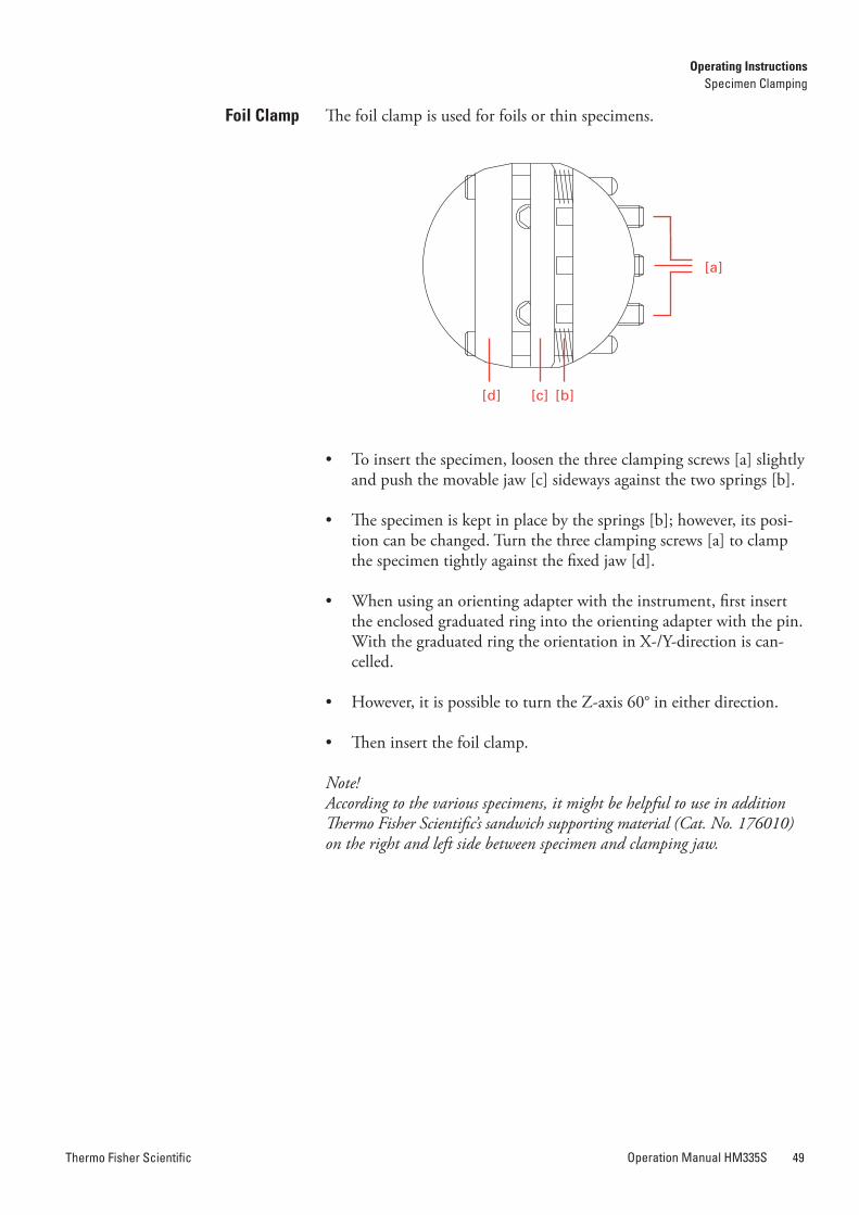
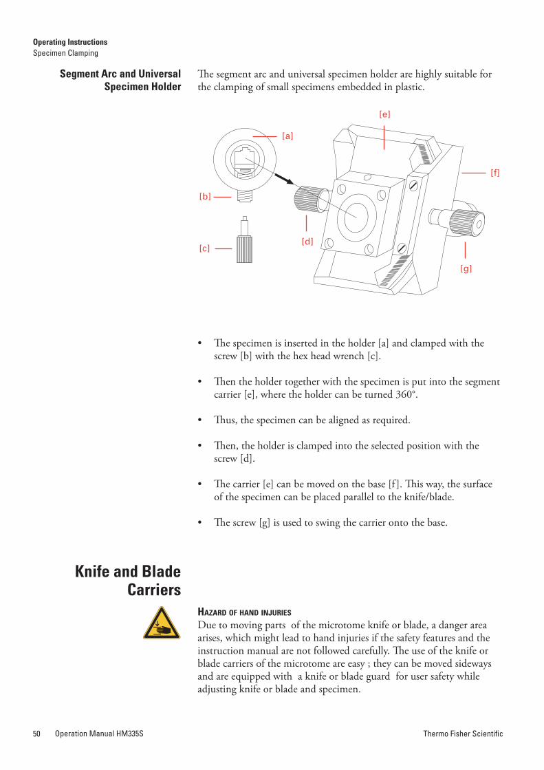
Thermo Fisher ScientificOperation Manual HM335S50 Thermo Fisher Scientific Operation Manual HM335S 51
The segment arc and universal specimen holder are highly suitable for the clamping of small specimens embedded in plastic.
• The specimen is inserted in the holder [a] and clamped with the screw [b] with the hex head wrench [c].
• Then the holder together with the specimen is put into the segment carrier [e], where the holder can be turned 360°.
• Thus, the specimen can be aligned as required.
• Then, the holder is clamped into the selected position with the screw [d].
• The carrier [e] can be moved on the base [f ]. This way, the surface of the specimen can be placed parallel to the knife/blade.
• The screw [g] is used to swing the carrier onto the base.
hazard of hand injuries
Due to moving parts of the microtome knife or blade, a danger area arises, which might lead to hand injuries if the safety features and the instruction manual are not followed carefully. The use of the knife or blade carriers of the microtome are easy ; they can be moved sideways and are equipped with a knife or blade guard for user safety while adjusting knife or blade and specimen.
Segment arc and universal Specimen holder
[a]
[b]
[f]
[d][c]
[e]
[g]
The disposable blade carrier ER is designed to take all commercially available high and low profile blades.
• Insert the blade into the slot behind the clamping plate [e] by turning the clamping lever [g] towards the front. Swing the bracket [d] to the front.
• Loosen the clamping lever [g] and, if necessary, slightly push the lower part of the clamping plate [e] as well.
• Insert the blade on the rail [c] and push it from the side to the middle.
• Afterwards, return the clamping lever [g] upright, thus locking the blade in position.
• After loosening the clamping lever [b] and after having moved the bracket [d] upwards, move the blade together with the entire upper part without having to loosen the blade clamping.
• This way, the entire cutting length of the blade can be used.
• Then tighten the clamping lever [b].
The lever [b] can be removed by pulling it off towards the side.
Disposable Blade Carrier “Er”
using Low Profile Blades
[b]
[d]
[a][k]
[e][i]
[c] [g]
[h]
[f]
Operating InstructionsSpecimen Clamping
Operating InstructionsKnife and Blade Carriers
Knife and Blade Carriers
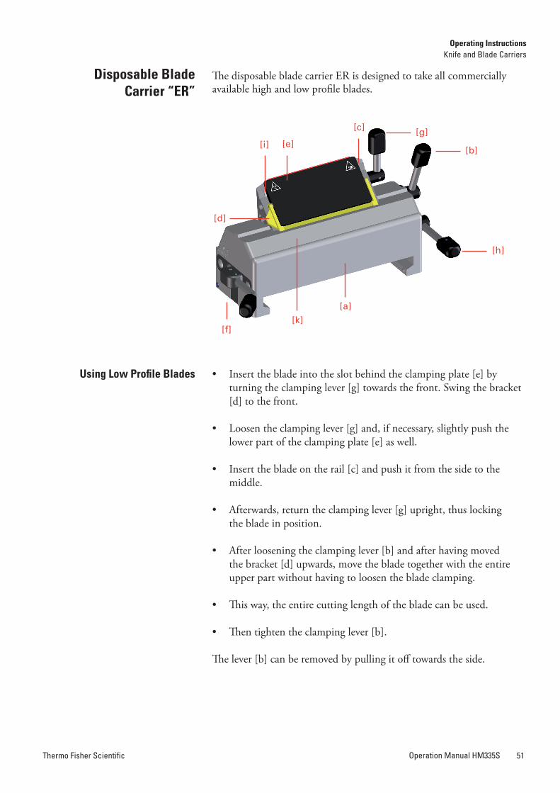
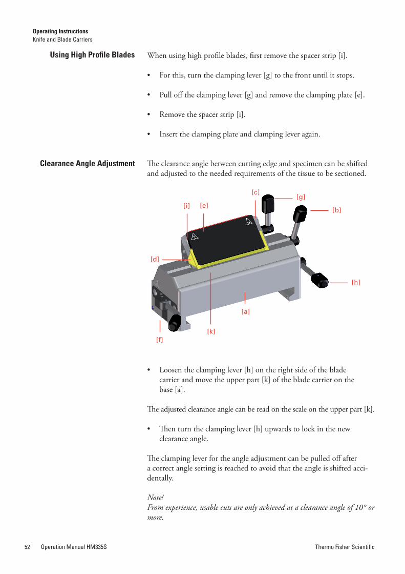
Thermo Fisher ScientificOperation Manual HM335S52 Thermo Fisher Scientific Operation Manual HM335S 53
Loosen the clamping lever [f ] on the left side of the blade carrier, to move the carrier forwards and backwards on the guide bars, this allows a rough adjustment of blade to specimen.
A bracket [d] on the clamping plate can be moved upwards over the bla-de for protection against injury.
The disposable blade carrier E is designed to take all commercially available high and low profile blades.
Insert the blade into the slot behind the clamping plate [e]
• When using high profile blades, first loosen the four screws [m] and remove the spacer strip [i].
• Turn the clamping lever [g] to the front.
• Swing the bracket with scale [d] to the front.
• A small gap between rail [c] and clamping plate [e] can be seen.
• Insert the blade on the rail [c] and push it from the side to the middle.
• Afterwards, return the clamping lever [g] upright, thus locking the blade in position.
When using high profile blades, first remove the spacer strip [i].
• For this, turn the clamping lever [g] to the front until it stops.
• Pull off the clamping lever [g] and remove the clamping plate [e].
• Remove the spacer strip [i].
• Insert the clamping plate and clamping lever again.
The clearance angle between cutting edge and specimen can be shifted and adjusted to the needed requirements of the tissue to be sectioned.
• Loosen the clamping lever [h] on the right side of the blade carrier and move the upper part [k] of the blade carrier on the base [a].
The adjusted clearance angle can be read on the scale on the upper part [k].
• Then turn the clamping lever [h] upwards to lock in the new clearance angle.
The clamping lever for the angle adjustment can be pulled off after a correct angle setting is reached to avoid that the angle is shifted acci-dentally.
Note!From experience, usable cuts are only achieved at a clearance angle of 10° or more.
using high Profile Blades
Clearance angle adjustment
Disposable Blade Carrier “E”
Inserting the Blade
[b]
[d]
[a]
[e][g]
[h]
[f][k]
[i]
[c]
[d]
[a]
[e][m]
[g]
[h]
[f]
[k]
[m]
[c]
[i]
Operating InstructionsKnife and Blade Carriers
Operating InstructionsKnife and Blade Carriers
Moving the Blade Carrier on the Console
Protection against Injury
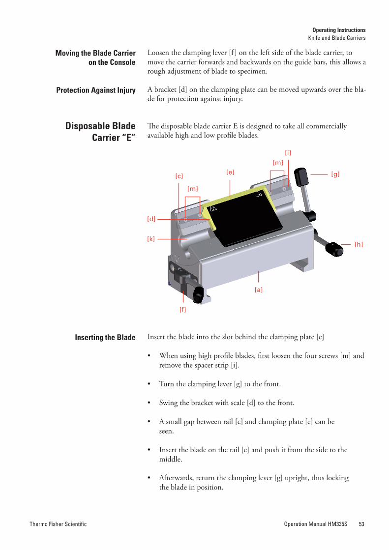
Thermo Fisher ScientificOperation Manual HM335S54 Thermo Fisher Scientific Operation Manual HM335S 55
Clearance angle adjustment
The bracket [d] is provided with a scale.
• After loosening the clamping lever [g] and after having moved the bracket [d] upwards, move the blade together with clamping plate [e] according to the scale to the left or right side.
• This way, the entire cutting length of the blade can be used. Then press the clamping lever [g] upwards.
• The levers [g] and [h] can be removed by pulling them off to wards the side.
• The lever [g] can also be used on the left side. This way, the blade can be clamped with the left hand.
The clearance angle between cutting edge and specimen can be shifted and adjusted to the requirements of the tissue to be sectioned.
• Loosen the clamping lever [h] on the right side of the blade carrier and move the upper part [k] of the blade carrier on the base [a].
• The adjusted clearance angle can be read on the scale of the upper part [k].
• Then turn the clamping lever [h] upwards to lock in the new clea-rance angle.
Note!By experience, usable cuts are only achieved at a clearance angle of 10° or more.
If the clamping lever [h] is loosened, the upper part [k] of the blade carrier can additionally be moved 1 cm to the left or right side. This way, the cutting edge can optimally be used. The clamping lever for the angle adjustment can be pulled off after a correct angle setting to avoid that the angle is shifted accidentally.
• Loosen the clamping lever [f ] on the left side of the blade carrier, to move the carrier forwards or backwards on the guide bars.This allows a rough adjustment of the blade to the specimen.
A bracket [d] on the clamping plate can be moved upwards over the blade for the protection against injury.
Moving the Blade Carrier on the Console
Protection against Injury
• To insert the knife, the clamping screws [g] must be unscrewed slightly so the knife can be pushed in from the side.
• The height of the knife is adjusted with the two knurled nuts [n].
If the cutting zone of the knife cannot be used anymore, it can be moved over its entire length to the left and right side by loosening the clamping screws [g]. This allows an optimal use of the entire knife edge.
Caution!When clamping the knife, please tighten the two clamping screws [g] simultaneously.
The clearance angle between cutting edge and specimen can be shifted and adjusted to the requirements of the tissue to be sectioned.
• Loosen the clamping lever [h] on the right side of the knife carrier and move the upper part [k] of the knife carrier on the base [a]. The adjusted clearance angle can be read on the side scale of the upper part [k].
• Then turn the clamping lever [h] upwards to lock in the new clearance angle.
The clamping lever [h] for the angle adjustment can be pulled off after a correct angle setting to avoid that the angle is shifted accidentally.
Note!By experience, usable cuts are only achieved at a clearance angle of 10° or more.
Knife Carrier “C”
Inserting the Knife
[f]
[a]
[d]
[h]
[g]
[k]
[e][n]
Operating InstructionsKnife and Blade Carriers
Operating InstructionsKnife and Blade Carriers
Clearance angle adjustment
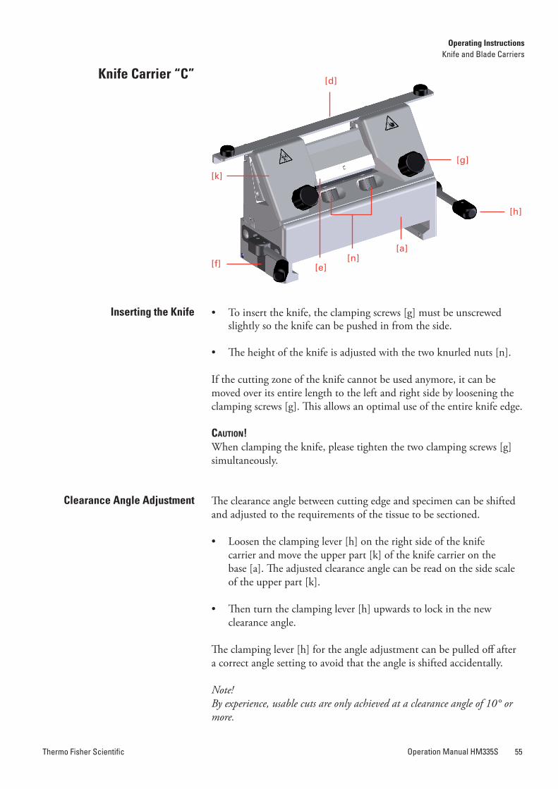
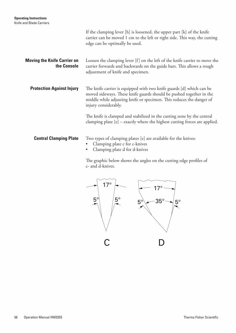
Thermo Fisher ScientificOperation Manual HM335S56 Thermo Fisher Scientific Operation Manual HM335S 57
If the clamping lever [h] is loosened, the upper part [k] of the knife carrier can be moved 1 cm to the left or right side. This way, the cutting edge can be optimally be used.
Loosen the clamping lever [f ] on the left of the knife carrier to move the carrier forwards and backwards on the guide bars. This allows a rough adjustment of knife and specimen.
The knife carrier is equipped with two knife guards [d] which can be moved sideways. These knife guards should be pushed together in the middle while adjusting knife or specimen. This reduces the danger of injury considerably.
The knife is clamped and stabilized in the cutting zone by the central clamping plate [e] – exactly where the highest cutting forces are applied.
Two types of clamping plates [e] are available for the knives:• Clamping plate c for c-knives• Clamping plate d for d-knives
The graphic below shows the angles on the cutting edge profiles of c- and d-knives.
Moving the Knife Carrier on the Console
Protection against Injury
Central Clamping Plate
C D
17° 17°
35°5° 5° 5° 5°
Frequent use of the clamping levers can cause the knife or blade carriers not to optimally clamp any longer. If the necessary readjustments are not made, it might even be possible that the knife or blade carriers can-not be clamped anymore.
If the clamping lever [f ] does not allow a sufficient clamping, the clamping can be adjusted as follows:
• Loosen the locking screw [a] on the lower side of the knife/blade carrier.
• Insert a pin into one of the holes of the adjusting screw [b] and turn the screw in the above shown directions.
• When the clamping is to be strengthened, turn the adjusting screw [b] to the right side.
• When the clamping is to be loosened, turn the adjusting screw [b] to the left side.
• Before inserting the knife or blade carrier again, tighten the set screw [a].
• Afterwards, push the knife or blade carrier onto the consoles and check the clamping function.
If necessary, repeat the above-mentioned process.
readjusting Knife or Blade Carriers
[f]
[f]
[b]
[b][a]
Operating InstructionsKnife and Blade Carriers
Operating InstructionsKnife and Blade Carriers
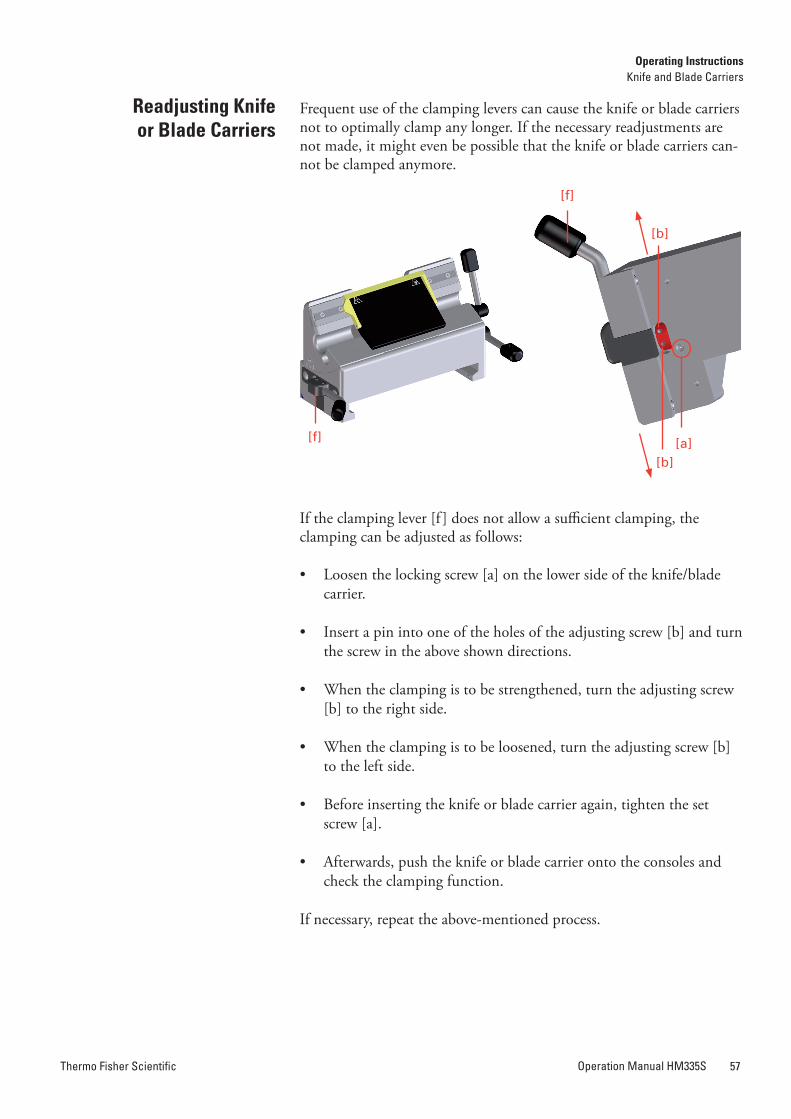
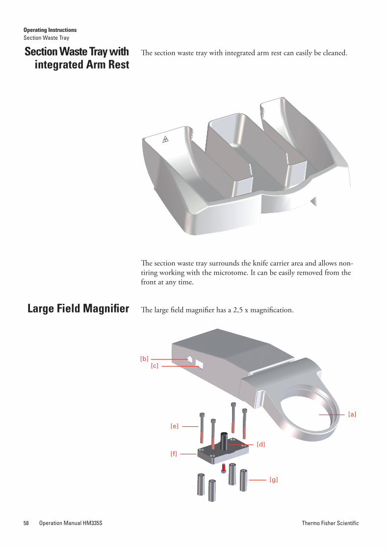
Thermo Fisher ScientificOperation Manual HM335S58 Thermo Fisher Scientific Operation Manual HM335S 59
Section Waste Tray with integrated arm rest
The section waste tray with integrated arm rest can easily be cleaned.
The section waste tray surrounds the knife carrier area and allows non-tiring working with the microtome. It can be easily removed from the front at any time.
The large field magnifier has a 2,5 x magnification.Large Field Magnifier
Connect the integrated light to the power outlet with the power cord [b] and turn it and off with the switch [c].
Caution!Before using the large field magnifier for the first time, please check if the voltage conditions at the installation site comply with the power requirements and frequency noted on the supply unit of the magnifier.
Please use the enclosed fastening elements to attach the magnifier to the microtome.
• Remove the cover plate on the upper side of the microtome hood.
• Remove the front plastic caps from the upper side of the housing.
• Carefully introduce the four sleeves [g] into the drilled holes with guidance of the screws [e].
Caution!Please be sure that the sleeves do not fall into the interior of the micro-tome!
Note!Make sure the plate [f ] is mounted in such a way that the peg [d] is closer to the front of the microtome!
• Put the plate [f ] on the sleeves and fasten it to the microtome with four screws [e].
• Put the movable plastic socket, which is located at the lower side of the magnifier, on the peg [d].
• The magnifier can be adjusted forwards and backwards for the most comfortable viewing position.
Note!If the large field magnifier is not used, slightly raise it and turn it sideways on the peg.
Installing the Large Field Magnifier on the Microtone
[g]
[b][c]
[e]
[f][d]
[a]
Operating InstructionsSection Waste Tray
Operating InstructionsLarge Field Magnifier
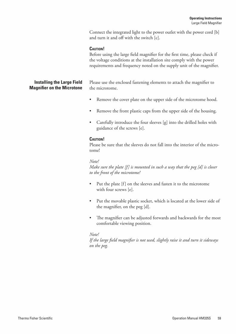
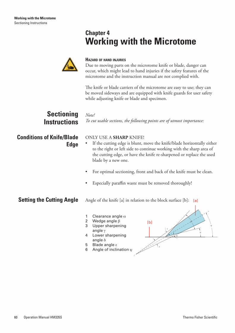
Thermo Fisher ScientificOperation Manual HM335S60 Thermo Fisher Scientific Operation Manual HM335S 61
The knife/blade must never be placed on an angle that is too flat since the knife/blade does not cut into the block at all this way. Only the rear side slides over the sectioning surface.
An angle, which is too steep, is also unfavorable as the knife/blade might vibrate too much while sectioning. The so-called “chatters“ ap-pear on the block surface as well as on the sections as parallel stripes having negative effects on the microscopical evaluation.
Sectioning Instructions
Chapter 4Working with the Microtome
hazard of hand injuries
Due to moving parts on the microtome knife or blade, danger can occur, which might lead to hand injuries if the safety features of the microtome and the instruction manual are not complied with.
The knife or blade carriers of the microtome are easy to use; they can be moved sideways and are equipped with knife guards for user safety while adjusting knife or blade and specimen.
Note!To cut usable sections, the following points are of utmost importance:
ONLY USE A SHARP KNIFE!• If the cutting edge is blunt, move the knife/blade horizontally either
to the right or left side to continue working with the sharp area of the cutting edge, or have the knife re-sharpened or replace the used blade by a new one.
• For optimal sectioning, front and back of the knife must be clean.
• Especially paraffin waste must be removed thoroughly!
Angle of the knife [a] in relation to the block surface [b]:
1 Clearance angle a2 Wedge angle b3 Upper sharpening angle g4 Lower sharpening angle d 5 Blade angle e6 Angle of inclination j
Setting the Cutting angle
Conditions of Knife/Blade Edge
[a]
[b]
Working with the MicrotomeSectioning Instructions
Working with the MicrotomeSectioning Instructions
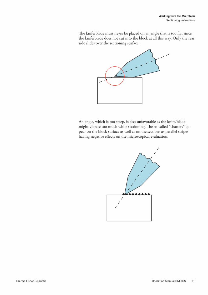
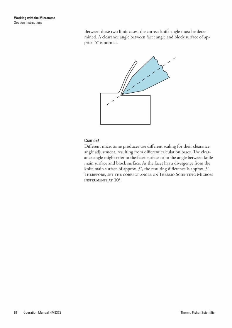
Thermo Fisher ScientificOperation Manual HM335S62 Thermo Fisher Scientific Operation Manual HM335S 63
how to avoid Malfunctions
Between these two limit cases, the correct knife angle must be deter-mined. A clearance angle between facet angle and block surface of ap-prox. 5° is normal.
Caution!Different microtome producer use different scaling for their clearance angle adjustment, resulting from different calculation bases. The clear-ance angle might refer to the facet surface or to the angle between knife main surface and block surface. As the facet has a divergence from the knife main surface of approx. 5°, the resulting difference is approx. 5°. Therefore, set the correct angle on Thermo Scientific Microm instruments at 10°.
Specimen preparation:When preparing specimens, be sure that a suitable embedding medium, fixation, dehydration and infiltration time are chosen.
Specimen temperature:Sectioning is carried out at ambient temperature (excluding frozen sections). If the temperature is too high, the paraffin softens. Therefore, avoid heating paraffin specimens by direct exposure to sunlight or other near sources of heat.
Tightening the clamping screws:Tighten all clamping screws and clamping levers on the knife/blade carrier, specimen holder and specimen orientation.
Selection of the knife/blade:Carefully select the required knife/blade material and profile.
Adjustment of the knife/blade:Carefully adjust the proper clearance angle of the knife: 5 – 7° for glass knives. For settings for diamond knives ask the knife manufacturer.Select a clearance angle adjustment of 5 – 15° according to the facet angle. Typically, adjust an angle of 10 – 12°.Take care to adjust knife height.
Cutting speed:Always cut at proper speed.
Note!General rule: The harder the material, the slower the cutting speed!
Trimming:Carefully bringing the knife/blade and specimen together.
Working with the MicrotomeSection Instructions
Working with the MicrotomeHow to Avoid Malfunctions
Thermo Fisher ScientificOperation Manual HM335S64 Thermo Fisher Scientific Operation Manual HM335S 65
Possible Sources of Errors – Cause and
removal
Problem Cause Solution
thick-thin-sections blunt knife/blade move knife/blade or insert a new one
knife/blade angle unfavorable clearance angle adjust knife/blade angle, until an optimal angle can be found
insufficient clamping on specimen clamping and/or knife/blade carrier
check all screw and clamping connections on specimen clamping and knife/blade carrier. Tighten them, if necessary
compressions blunt knife/blade move knife/blade or insert a new one
specimen too warm cool specimen
unfavorable clearance angle try clearance angle adjustments until an opti-mal angle can be found
cutting speed too high turn hand wheel slower or reduce the speed of the cutting drive motor
“chatter“ on sections cutting speed too high turn hand wheel slower or reduce the speed of the cutting drive motor
unfavorable clearance angle try clearance angle adjustments until an opti-mal angle can be found
insufficient clamping on specimen clamping and/or knife/blade carrier
check all screw and clamping connections on specimen clamping and knife/blade carrier. Tighten them, if necessary
feed is not working, no sections are produced
front end position has been reached move specimen backwards with the course feed motor
coarse feed motor is blocked contact a service technician
Tight Hand Wheel, partly debris and section waste between microtome and base plate
remove section waste and clean microtome
tight hand wheel during the entire movement
dirty link block contact a service technician
instrument cannot be turned on power cord not correctly connected check power cord
defective main fuse check/replace the fuses in thefuse box
cutting drive motor cannot be started emergency stop button is activated deactivate the emergency stop button
foot pedal (optional) or interlock connector not connected
connect foot pedal (optional) or interlock plug
mechanical hand wheel brake activated deactivate the hand wheel brake by moving the lever down
Note!In case of malfunctions and/or service work, please turn off the instrument and contact your local dealer.
Cleaning and Care
Chapter 5Maintenance and Care
Cleaning and care of the microtome should be carried out daily. Please proceed as follows:
• Turn off the mains switch of the instrument.
• Activate the mechanical hand wheel brake.
• Remove the knife/blade from the knife/blade carrier. Clean it and store the knife in a case!
• Remove section waste by using a dry brush.
• Pull the section waste tray towards the front and dispose of the sec-tion waste according to your specific lab regulations.
Caution!Never put the knife with the cutting edge upward on the table!!
• Loosen the clamping lever on the left side of the knife or blade car-rier and pull the knife/blade carrier towards the front.
• Clean the operating controls and the surfaces of the knife or blade carrier, especially the space where the knife or blade is installed.
• Clean the consoles, hand wheel, specimen clamping system, speci-men orientation as well as the base plate and housing.
Note!Mild domestic cleaners can be used to clean the microtome. Do not use ag-gressive cleaners or solvents, as the paint and plastic parts can be affected.
Note!In order to avoid electrostatic loadings, clean housing only by using cotton or paper cloths. We highly recommend to not use any microfiber or polyester cloths!
Warning!When getting in contact with cleaning agents or paraffin repellents, e.g. Para Gard, the surface of the black cover ribbon behind the specimen clamping might be damaged. Please take care that the cover ribbon does not get in contact with these agents when cleaning the housing, knife or blade carrier or the base plate.
Working with the Microtome Maintenance and CareCleaning and Care
Thermo Fisher ScientificOperation Manual HM335S66 Thermo Fisher Scientific Operation Manual HM335S 67
• Before starting sectioning, instrument, knife or blade carrier and section waste tray should be treated with commercially available paraffin repellent.
Note!This considerably reduces the adhesive force of paraffin waste on the indi-vidual parts of the microtome.
To secure section quality and to insure proper functioning of the micro-tome, it is recommended that a routine maintenance be performed by a trained service technician once a year.
Thermo Fisher Scientific offers a service contract which guarantees that your instrument is always in perfect condition. For more information, please contact the nearest ThermoFisher Scientific sales office.
Note!We strongly recommend to not carrying out repair by yourself. All warran-ties and guarantees would then be null and void! Repair work must only be carried out by an authorized service technician.
Maintenance
The two power fuses are located above the main switch [a] on the rear side of the microtome.
• To replace the two fuses, turn off the main switch [a] of the instru-ment and unplug it.
• Then open the cover [b] using a flat screwdriver.
• Pull out the fuse holders and replace the fuses with new ones.
• Put back the fuse holder completly and close the cover [b].
For power requirements 100 – 240 V, 2 fuses 2,5 AT slow-blow
replacement Work
rating of Fuses
replacing the Fuses:
annual routineMaintenance
Service Contract
[b]
[a]
Maintenance and CareMaintenance
Maintenance and CareReplacement Work
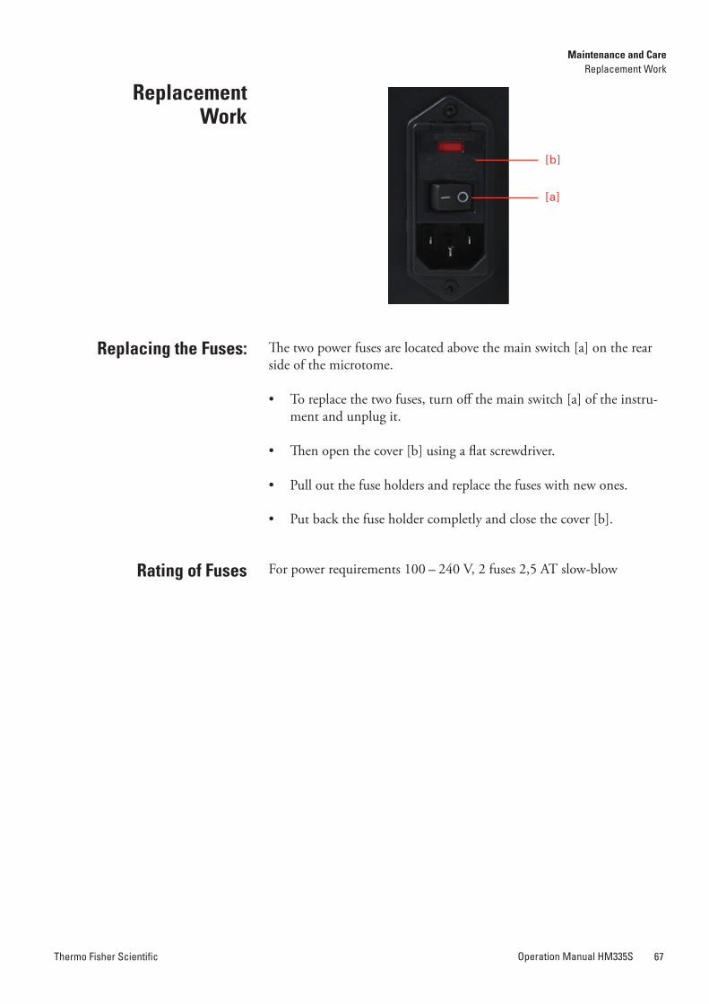
Thermo Fisher ScientificOperation Manual HM335S68 Thermo Fisher Scientific Operation Manual HM335S 69
returning the Instru-ment for repair or
routine Maintenance
Chapter 6Conditions for Transportation
Repair or maintenance works is normally carried out at the site of ins-tallation. If this is not possible for some specific reasons, the instrument can be returned to ThermoFisher Scientific. The contact address can be found in the front of this instruction manual.
To guarantee a trouble-free function of the instrument after transporta-tion, please follow the instructions for transportation preparations.
In addition, the conditions for storage and transportation as mentioned in the Technical Data Sheet (see page 16), must be observed during the entire transportation.
BiohazardPlease also note the precautionary measures described in our safety pre-cautions concerning biological hazards!
• Turn off the mains switch of the instrument.
• Activate the mechanical hand wheel brake.
• Remove knife or blade and store it in a safe place.
• Remove the section waste tray.
• Turn off the mains switch of the instrument.
• Activate the mechanical hand wheel brake.
• Remove knife or blade and store it in a safe place.
• Remove the section waste tray, the operating panel, the knife/blade carrier and the specimen clamp. These parts have to be packed separatly.
• To lift the instrument, use the recessed grip on the lower front and rear side of the instrument.
Caution!During transport, do not move the instrument by holding the hand wheel handle. Danger of injury!
Use the original packing material since it protects the instrument opti-mally during transport.
Caution!Shipping of the instrument requires original packaging materials! Da-mages caused by shipping in non original packaging is not covered by the manufacturer warranty! Any damage repairs resulting from shipping in other material is charged to the shipping party. We reserve the right NOT to repair the instrument if it is too badly damaged.
To order original packaging materials if needed, please contact Thermo Fisher Scientific International or your local, authorised Thermo Fisher Scientific dealer.
Caution!The user must insure clean and safe conditions of the instrument when returning it to an appropriate service provider.
Note!In case the instrument or parts of the instruments is/are sent to Thermo Fisher Scientific or to one of its representatives in a condition which has potential danger of infection, the instrument and/or the part(s) will be returned to the customer in an unrepaired status. Costs for this are to be charged to the customer.
After the final shutdown of the instrument, we recommend to contact a local recycling company for the disposal according to the nationally applicable regulations.
TO BE APPLIED IN THE COUNTRIES OF THE EUROPEAN UNION AND OTHER EUROPEAN COUNTRIES WITH A SE-PARATE COLLECTING SYSTEM WITHIN THE WASTE MA-NAGEMENT.
Under no circumstances is it allowed to dispose of the instrument together with ordinary domestic waste.
Please dispose of your instrument separately from other waste to not harm our environment and/or human health by uncontrolled waste disposal.
Recycle your instrument whenever possible to support the sustainable recycling of material resources.
Industrial users should contact their suppliers and observe the condi-tions of the contract. This product must not be disposed of together with other commercial waste.
Please contact your supplier!
Disposal of the Instrument after Final
Shutdown
Measures for Taking out of Operation
For Transporting Outside Closed Buildings, please Observe
the Following Measures
Conditions for TransportationReturning the Instrument
Conditions for TransportationDisposal after Shutdown
Thermo Fisher ScientificOperation Manual HM335S70 Thermo Fisher Scientific Operation Manual HM335S 71
Chapter 7Warranty Statement and Certifi-cation
We are proud of our quality and reliability, and of our after sales service. We continuously strive to improve our service to our customers.
Please ask your distributor or representative about Service Contracts which can keep your purchase in peak condition for many years to come.
Warranty provisions may vary to comply with differences in national and regional legislation, and you can find detailed information in your delivery documents or from your dealer or representative.
Please note that your warranty may be invalidated if:
• Theinstrumentismodifiedinanyway.
• AccessoriesareusedthatarenotapprovedbyThermoScientific,or;
• The instrument is not operated or maintained in accordance with the instructions in this Operator Guide.
The designated product carries the CE sign and complies with the laid down regulation:
DIRECTIVE 98/79/EC OF THE EUROPEAN PARLIAMENT AND OF THE COUNCILof 27 October 1998 on in-vitro diagnostic medical devices
The designated product complies with the EC regulations by strictly observing the following norms:
DIN EN ISO 9001Quality management systems – Requirements
DIN EN ISO 13485Quality management systems – Medical devices
DIN EN ISO 14971Medical devices – Application of risk management to medical devices
Certification
DIN EN 61010-1Safety requirements for electrical equipment for measurement, control and laboratory use Part 1: General requirements
DIN EN 61010-2-101Safety requirements for electrical equipment for measurement, control and laboratory use Part 2–101: Particular requirements for In-Vitro-Diagnostic (ivD) Medical Instruments.
DIN EN 61326-1Electrical equipment for measurement, control and laboratory use – EMC requirementsPart 1: General requirements
DIN EN 61326-2-6Electrical equipment for measurement, control and laboratory use – EMC requirementsPart 2–6: Particular requirements for In-Vitro-Diagnostic (ivD) Medi-cal Instruments
Warranty and CertificationsWarranty
Warranty and CertificationsCertification
Warranty

Thermo Fisher ScientificOperation Manual HM335S72 Thermo Fisher Scientific Operation Manual HM335S 73

Thermo Fisher ScientificOperation Manual HM335S72 Thermo Fisher Scientific Operation Manual HM335S 73

Thermo Fisher ScientificOperation Manual HM335S74
anatomical Pathology
Robert-Bosch-Strasse 4969190 WalldorfGERMANY+ 49 (0) 6227-8360
4481 Campus DriveKalamazoo, MI 49008USA+ 1 (800) 522-7270
www.thermofisher.com