Thermal Balloon Endometrial Ablation System This Operator ... · Normal Pap Smear and endometrial...
32
Thermal Balloon Endometrial Ablation System 1 This Operator’s Manual is designed for use with the Thermablate EAS Endometrial Ablation System NOTE: The instructions that accompany the disposable cartridge may contain a more recent revision of the Thermablate EAS system instructions than this manual. Read all directions, cautions, and warnings prior to use. Copyright © 2016 by Idoman Teoranta. All rights reserved. No part of this manual may be reproduced or transmitted in any form or by any means, electronic or mechanical, including photocopying, recording, or any information storage and retrieval system, without permission in writing from the publisher. Idoman Teoranta, Killateeaun, Tourmakeady, Co. Mayo, Ireland. LS2607 Rev. D
Transcript of Thermal Balloon Endometrial Ablation System This Operator ... · Normal Pap Smear and endometrial...

Thermal Balloon Endometrial Ablation System
1
This Operator’s Manual is designed for use with the Thermablate EAS Endometrial Ablation System
NOTE: The instructions that accompany the disposable cartridge may contain a more recent revision of the Thermablate EAS system instructions than this manual.
Read all directions, cautions, and warnings prior to use.
Copyright © 2016 by Idoman Teoranta. All rights reserved. No part of this manual may be reproduced or transmitted in any form or by any means, electronic or mechanical, including photocopying, recording, or any information storage and retrieval system, without permission in writing from the publisher.
Idoman Teoranta, Killateeaun, Tourmakeady, Co. Mayo, Ireland.
LS2607 Rev. D

Operators Manual
2
TABLE OF CONTENTS
1. DEVICE DESCRIPTION 3 1.1 Treatment Control Unit (TCU) 3 1.2 Disposable Cartridge 3 1.3 Power Supply 4 1.4 TCU Stand 4 1.5 Carrying Case 5
2. PRINCIPLES OF OPERATION 6
3. SAFETY INFORMATION 7 3.1 Indications For Use 7 3.2 Patient Selection 7 3.3 Recommended Pre Assessment of Uterus and Cavity 7 3.4 Contraindications 7 3.5 Warnings 8 3.6 Potential Adverse Events 9 3.7 Patient Counselling 9 3.8 Preparation of Patient 9 3.9 Recommended Pre-Treatment of endometrium 9
4. DIRECTIONS FOR USE 10 4.1 Set-Up 10 4.2 Opening and Installing the Thermablate EAS Sterile Disposable Cartridge 10 4.3 Warm-Up 12 4.4 Patient Preparation 13 4.5 Treatment 13 4.6 Post-Treatment 17 5. CLEANING, MAINTENANCE, STORAGE AND TRANSPORTATION 18 5.1 Cleaning 18 5.2 Maintenance 18 5.3 Storage and Transport 19
6. TECHNICAL INFORMATION 20 6.1 Technical Specifications 20 6.2 Standards 21
7. ERROR MESSAGES AND TROUBLESHOOTING 25
8. LIMITED WARRANTY 28
9. SYMBOLS USED ON LABELLING 29
10. NOTES 31

Operators Manual
3
1. Device Description
The Thermablate EAS system is a software-controlled device designed to ablate uterine tissue with thermal
energy. The Thermablate EAS system includes the following components:
1.1 TREATMENT CONTROL UNIT (TCU)
Figure 1. Thermablate EAS Treatment Control Unit, TCU (REF. No. 22001)
This handheld non-sterile device, weighing less than 1Kg, controls the treatment settings (time, pressure,
and temperature) through a computerized system that operates the electromechanical heating and
pumping/draining subsystems. The TCU has an LCD that provides pertinent information to the user: warm-up cycle, leak checks, treatment cycle, and completion of treatment are all clearly indicated. The TCU (REF.
No. 22001) is reusable, requiring only cleaning between uses over its working lifetime. The TCU is not user serviceable, see Section 5 for details.
1.2 DISPOSABLE CARTRIDGE
Figure 2. Thermablate EAS Disposable Cartridge (REF. No. 21004)
The sterilised catheter-balloon Disposable Cartridge (REF. No. 21004) is the actual treatment component
(applied part) of the Thermablate EAS device. Its pre-shaped silicone balloon directly contacts the endometrial tissue to perform thermal ablation. The Disposable Cartridge is a SINGLE-USE device. It is
designed for use with the Thermablate EAS TCU only.

Operators Manual
4
1.3 POWER SUPPLY
Figure 3. Thermablate TCU Power Supply (Réf. 23001)
The Power Supply (REF. No. 23001) converts 100-240VAC to 24VDC for the TCU. It is supplied with a
relevant power cord which consists of IEC C13 connector, H05VV-F3G 1.0mm² cable and suitable plug for country. (please consult distributor).
Class I ME Equipment WARNING: To avoid the risk of electric shock, this equipment must only
be connected to a mains supply with a protective earth.
1.4 TCU STAND
Figure 4. TCU Thermablate Stand (Réf. 24001)
The Stand (REF. No. 24001) provided with the Thermablate EAS device is a stable support that holds the TCU in the horizontal position during the warm-up cycle of the system. It also offers a sanitary rest when the unit
is not in use.

Operators Manual
5
1.5 CARRYING CASE
Figure 5. Thermablate EAS Carrying Case (Réf. 25001)
The Thermablate EAS TCU Kit is supplied in a Carrying Case (REF. No. 25001) to facilitate its transportation, handling, and storage.
This TCU Kit (REF. No. 22101) comprises the TCU, its Power Supply, Stand, and Carrying Case.
Operators Manual
6
2. PRINCIPLES OF OPERATION
The ablating heat source of the Thermablate EAS system is the treatment liquid, which is supplied inside
the diaphragm of the Disposable Cartridge. This diaphragm, surrounded by an aluminum shield, is inserted
into the heating chamber of the TCU. Once the treatment liquid is heated up to approximately 173°C, the
balloon is inserted into the uterine cavity. The physician formally initiates the ablation treatment by holding
the treatment button. Using a controlled pneumatic pressure with set point of approximately 220 mmHg,
the treatment liquid is forced into the balloon. The treatment liquid cools as it travels through the catheter
and into the balloon to approximately 150°C. Temperatures at the endometrial lining in uterine models are
approximately 100°C.
During treatment, the TCU performs a series of pressurization and depressurization cycles to homogenize
the temperature of the liquid in the balloon. This ensures a uniform endometrial remodelling throughout
most of the uterine lining. The total treatment takes less than 3 minutes to complete, a nominal 4-5 mm
treatment depth is achieved.

Operators Manual
7
3. SAFETY INFORMATION
3.1 INDICATIONS FOR USE
The Thermablate EAS System is a thermal ablation device intended to ablate the endometrial lining of
the uterus in women suffering from excessive uterine bleeding due to benign causes for whom
childbearing is complete.
3.2 PATIENT SELECTION
Excessive uterine bleeding can be caused by a variety of underlying problems including but not limited
to endometrial cancer, myomas, polyps, and drugs. Patients should always be evaluated to determine if
there are underlying causes of their excessive uterine bleeding before any treatment option is initiated.
The patient selection criteria are:
Documented diagnosis of excessive uterine bleeding with no underlying causes
Completed childbearing
Pre-menopausal
Normal uterine cavity with sounding between 8 cm and 12 cm, inclusive
Normal Pap Smear and endometrial biopsy
Does not present any of the contraindications below.
3.3 RECOMMENDED PRE ASSESSMENT OF UTERUS AND CAVITY
Assessment of the cavity for patient selection can include Transvaginal or Transabdominal Ultrasound,
Saline / Gel Infusion Sonography (SIS) / (GIS), and Hysteroscopy. Sounding length of uterine cavity can be taken during office biopsy or requested with the ultrasound
3.4 CONTRAINDICATIONS
The device is contraindicated for use in:
• A patient with a uterine sounding less than 8 cm or in excess of 12 cm (external os to fundus) • A patient with active pelvic inflammatory disease
• A patient with known or suspected endometrial carcinoma (uterine cancer) or premalignant change of the endometrium, such as unresolved complex (adenomatous) hyperplasia
• A patient with history of pelvic malignancy within the past 5 years
• A patient with submucous / intramural myomas greater than 3.0 cm such that the uterine cavity is significantly distorted
• A patient with intracavitary lesions (Type 0 or 1 myoma or polyps of any size) as documented
by hysteroscopy, contrast infusion sonohysterogram (CIS), or MRI performed in the last 6
months. Ablation can be performed if polyp is removed prior to procedure.
• A patient with a septate uterus
• A patient with any anatomic or pathologic condition in which weakness of the myometrium
could exist, such as history of previous classical caesarean sections or transmural myomectomy
• A patient that has had three or more, lower segment C sections and where the linear scar
thickness in those patients is less than 8mm
• A patient who is pregnant or who wants to become pregnant in the future
• A patient with active genital or urinary tract infection at the time of procedure (e.g.cervicitis,
vaginitis, endometritis, salpingitis, or cystitis) • A patient with an IUD (Intra-Uterine Device) currently in place
• A patient less than 6 months post-partum.

Operators Manual
8
3.5 WARNINGS
Only medical professionals who have experience in performing procedures within the uterine cavity,
such as IUD insertions or dilation and curettage, are suitably trained, have adequate knowledge and
familiarity with the Thermablate EAS system should perform endometrial ablation using this device.
Read all directions, cautions, and warnings prior to use. This manual provides directions for using
the Thermablate EAS system. Failure to follow any instructions or to heed any warnings or
precautions could result in serious injury to the patient and/or the user.
This device is intended for use only in women who do not desire to bear children because the
likelihood of pregnancy is significantly decreased following this procedure.
Endometrial ablation using the Thermablate EAS system is not a sterilization procedure. Pregnancies
after ablation can be dangerous for both mother and foetus.
Endometrial ablation procedures do not eliminate the potential for endometrial hyperplasia or
adenocarcinoma of the endometrium, and may diminish the physician’s ability to detect or make a
diagnosis of such pathology.
The Thermablate EAS Disposable Cartridge is for SINGLE-USE only – do not
reuse, or re-sterilize.
Use caution not to perforate the uterine wall during dilation, sounding, or curettage (if performed).
If a perforation is suspected, a hysteroscopy must be performed.
Do not initiate the procedure if perforation of the uterine wall or the creation of a false passage is
confirmed during the hysteroscopy performed just prior to the insertion of the balloon.
Do not perform same day Thermablate EAS procedure and hysteroscopic tubal
occlusion/sterilization.
Thermablate EAS procedure can be safely and effectively performed with nickel titanium inserts in place, however the procedure should only be performed after the 3 month tubal occlusion
confirmation test.
If you suspect that the treatment liquid is leaking from the balloon during treatment, activate the
―Emergency Stop‖ button or turn the ―POWER SWITCH‖ to the ―OFF‖ position and then to the ―ON‖
position again, which will cause the TCU to apply a vacuum to withdraw any remaining liquid from
the balloon. Withdraw the balloon from the patient only when the LCD of TCU indicates to do so.
Place a gauze sponge into the vagina to absorb any liquid that may have collected there, and
remove the sponge. Evaluate the patient for evidence of thermal injury to cervix, vagina and
perineum. Instruct the patient regarding signs or symptoms of thermal injury to bowel or bladder.
The Thermablate EAS TCU, Disposable Cartridge, Power Supply, and TCU Stand are designed as a
system. To ensure proper function, never use other components with the Thermablate EAS device.
After each use, follow the TCU cleaning procedure thoroughly.
REPEAT BALLOON ABLATIONS ARE CONTRAINDICATED
As the endometrial cavity following any kind of endometrial ablation is most likely distorted, repeat
ablation should not be attempted with Thermablate EAS. Patients requiring further treatment after
thermal balloon ablation should be treated medically, by resectoscopic endometrial ablation, or by
hysterectomy. Repeat resectoscopic ablation / resection should be attempted only by experienced
hysteroscopists since the complications may be severe.
The outside temperature measured on the disposable cartridge sheath can reach a maximum of
80°C during treatment cycle. This has been confirmed, in clinical studies and historical data, that the
heat lacks sufficient energy to cause any heat transfer to surrounding area. To eliminate any potential for patient discomfort in some circumstances Medical Equipment should not to be placed
against exposed flesh during treatment.

Operators Manual
9
3.6 POTENTIAL ADVERSE EFFECTS
The following adverse events are potentially associated with endometrial ablation:
• Pelvic cramping
• Nausea and vomiting
• Perforation of the uterus
• Rupture of the uterus
• Thermal injury to adjacent tissue/organs
• Heated liquid escaping into the cervix, vagina, or fallopian tubes
• Infection
• Post-ablation tubal sterilization syndrome ( PATSS)
• Haematometra.
3.7 PATIENT COUNSELLING
As with any procedure, the physician needs to discuss the risks, benefits, and
alternatives with the patient prior to performing endometrial ablation.
The device is intended for use in women who do not desire to bear children because the likelihood of pregnancy is significantly decreased following this procedure.
Patients of childbearing capability should be counselled that endometrial ablation is not a sterilization
procedure and should be provided with an appropriate birth control method. These patients should be
cautioned of the potential complications that may ensue if they should become pregnant.
Vaginal discharge is typically experienced during the first few days following ablation
and may last as long as a few weeks. Generally, the discharge is described as: bloody
during the first few days; serosanguineous by approximately one week; then profuse
and watery thereafter. Excessive pain, heavy bleeding, foul smelling discharge or fever should be
reported to the physician.
3.8 PREPARATION OF THE PATIENT
Appropriate sterile technique should be used to prepare the patient for procedure. Upon discretion of
the physician, thinning of the endometrium can be performed either with hormonal agents administered
prior to treatment, by timing the treatment to the early proliferative phase of the menstrual cycle, or by
a gentle suction curettage performed immediately prior to the procedure. It is recommended that a
non-steroidal anti-inflammatory drug (NSAID) be given at least one hour prior to the procedure.
Antibiotics can be prescribed as per the physician’s practice.
Anaesthesia may include a paracervical or intracervical block, intravenous sedation, or light general
anaesthesia at the physician’s discretion.
3.9 RECOMMENDED PRE TREATMENT OF ENDOMETRIUM
• Oral Contraceptives (Recommended for minimum 21 days until day of treatment)
• An estrogen/progesting combined preparation may be administered daily by mouth or monthly per vagina
• Timing of the menstrual Cycle
• Suction Curettage (if necessary)
• GnRH analogues minimum four weeks recommended only for patients with a uterine sounding ≥ 10 cm

Operators Manual
10
4. DIRECTIONS FOR USE
4.1 SET-UP
1. CHECK THAT THE FOLLOWING ITEMS ARE PRESENT WITH THE THERMABLATE EAS
DEVICE :
• One (1) Sterile Disposable (Single-Use) Cartridge
• One (1) Treatment Control Unit (TCU)
• One (1) Universal-Input Power Supply
• One (1) Power Cord (to match local AC power receptacles)
• One (1) TCU Stand
Frequently used Functions:
Operator should make themselves aware of the following functions.
On / Of Power switch located on TCU
Emergency Stop Button located on LCD overlay on top of TCU
Blue Treatment Trigger Switch located on front of TCU handle.
2. Place TCU in Stand.
3. Ensure the ―POWER SWITCH‖ is in the ―OFF‖ position.
4. Connect the Power Supply to TCU (as shown below). Plug the Power Cord into both the Power
Supply and the wall power outlet. Ensure that all connections are firmly connected. Ensure that the
―POWER SWITCH‖ and mains plug can be easily accessed to disconnect power to the TCU.
To make connection line up the two power connectors as shown above and twist to lock.
To disconnect unit slide yellow buttons on connectors to unlock and twist connectors in direction
shown by arrows on yellow buttons.
5. Ensure that the device is positioned to allow ease of access to the patient during treatment, avoiding any hindrances, stretching or obstructions. Also ensure that no cables or accessories are placed in a
dangerous manner or position.
4.2 OPENING AND INSTALLING THE THERMABLATE EAS STERILE DISPOSABLE CARTRIDGE
1. The Disposable Cartridge is inside a pouch (Pouch made of clear film and Tyvek webs).The pouch is
inside a tube with lids. The tube is inside a foil vacuum bag designed to be peeled open. ONLY THE
CONTENTS OF THE FOIL BAG ARE DEEMED TO BE IN A STERILE STATE. The foil bag is inside a
cardboard box.
2. Check expiry date. DO NOT USE the Disposable Cartridge if it has expired.

Operators Manual
11
3. Open cardboard box.
4. Remove foil vacuum bag from cardboard box.
5. Ensure vacuum is intact. If it is not, DO NOT USE the Disposable Cartridge, use another Disposable
Cartridge instead.
6. Peel open foil vacuum bag.
7. Remove tube from the foil vacuum bag. Do not discard plastic tube but place aside for use in safe
disposal of disposable cartridge after use.
8. Remove the lid with label attached from the tube by tearing the blue cap where indicated
by the symbol.
9. Remove sterile bag. DO NOT USE the Disposable Cartridge if the sterile bag is open or damaged.
Peel open sterile bag to remove cartridge using standard aseptic technique.
10. Install Disposable Cartridge in the TCU, by lining up the 2 pins on the cartridge with the 2 slots in the TCU, and rotating it clockwise, as shown in the figure below.
Ensure that ―This Side Up‖ and the guidance markings are visible on the top side of the catheter.
Leave the plastic balloon cover on.
Figure 6. Installation of Disposable Cartridge
Operators Manual
12
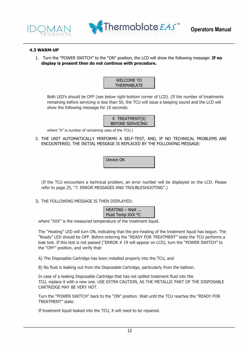
4.3 WARM-UP
1. Turn the ―POWER SWITCH‖ to the ―ON‖ position, the LCD will show the following message: If no
display is present then do not continue with procedure.
WELCOME TO
THERMABLATE
Both LED’s should be OFF (see below right-bottom corner of LCD). (If the number of treatments
remaining before servicing is less than 50, the TCU will issue a beeping sound and the LCD will
show the following message for 10 seconds:
X TREATMENT(S)
BEFORE SERVICING
where ―X‖ is number of remaining uses of the TCU.)
2. THE UNIT AUTOMATICALLY PERFORMS A SELF-TEST, AND, IF NO TECHNICAL PROBLEMS ARE
ENCOUNTERED, THE INITIAL MESSAGE IS REPLACED BY THE FOLLOWING MESSAGE:
Device OK
(If the TCU encounters a technical problem, an error number will be displayed on the LCD. Please
refer to page 25, ―7. ERROR MESSAGES AND TROUBLESHOOTING‖.)
3. THE FOLLOWING MESSAGE IS THEN DISPLAYED:
HEATING – Wait ...
Fluid Temp XXX °C
where ―XXX‖ is the measured temperature of the treatment liquid.
The ―Heating‖ LED will turn ON, indicating that the pre-heating of the treatment liquid has begun. The
―Ready‖ LED should be OFF. Before entering the ―READY FOR TREATMENT‖ state the TCU performs a
leak test. If this test is not passed (―ERROR # 19 will appear on LCD), turn the ―POWER SWITCH‖ to
the ―OFF‖ position, and verify that:
A) The Disposable Cartridge has been installed properly into the TCU, and
B) No fluid is leaking out from the Disposable Cartridge, particularly from the balloon.
In case of a leaking Disposable Cartridge that has not spilled treatment fluid into the
TCU, replace it with a new one. USE EXTRA CAUTION, AS THE METALLIC PART OF THE DISPOSABLE
CARTRIDGE MAY BE VERY HOT.
Turn the ―POWER SWITCH‖ back to the ―ON‖ position. Wait until the TCU reaches the ―READY FOR
TREATMENT‖ state.
If treatment liquid leaked into the TCU, it will need to be repaired.

Operators Manual
13
4.4 PATIENT PREPARATION
1. Provide patient with adequate analgesia.
2. During and/or prior to the warm up of the treatment fluid, patient preparation may be performed.
Appropriate sterile technique for vaginal/ cervical preparation should be used.
3. Place patient in dorsal lithotomy position.
4.5 TREATMENT
After approximately 12 minutes, the LCD will show ‖READY FOR TREATMENT‖ (see below) and the TCU
will beep, indicating that the liquid has been heated up to treatment temperature (approximately 173°C)
and the treatment procedure can be initiated. The ―Heating‖ LED will turn OFF and the ―Ready‖ LED will
turn ON. The LCD Display reads:
READY
FOR TREATMENT
NOTICE :
If the system is left unused, the treatment temperature will be maintained for 35 minutes. After this period , the system will automatically turn OFF. To re-initiate Warm-Up, turn the « POWER
SWITCH » to the « OFF » position, and ON again to restart the process. The Disposable Cartridge must not be used if it has been heated up and cooled down more than twice or exposed to
ambient air for more than 2 hours.
WARNING
IF THE BALLOON IS NOT COMPLETELY DEFLATED AND LIQUID AND / OR GAS IS SEEN IN BALLOON DURING ―READY FOR TREATMENT‖ STATE, DO NOT PROCEED WITH THE
TREATMENT. Instead, turn ―POWER SWITCH‖ to the ―OFF‖ position, disconnect the power cord and substitute the Disposable Cartridge, and restart the process
WARNING
IF THE BALLOON COVER CANNOT BE EASILY REMOVED FROM THE BALLOON, DUE TO PRESSURE IN THE BALLOON, DO NOT DETACH CARTRIDGE FROM TCU. Instead, turn the
―POWER SWITCH‖ to the ―OFF‖ position, disconnect power cord and cool down both TCU and Cartridge together until Balloon Cover can be easily removed. Remove Cartridge carefully from
TCU, verify no fluid leaking out to the TCU, substitute Disposable Cartridge, and restart the process
CAUTION
Patients with either acutely anteverted or retroverted uterus, or a fixed uterus (e.g. due to significant endometriosis or adhesions), or those that have had previous uterine surgery are at a higher risk.
Particular attention should be paid to the angulation of the uterine sound, cervical dilator and Thermablate catheter during insertion.
1. Conduct pelvic examination to confirm position of the uterus.
2. Insert Speculum.
3. Apply tenaculum. 4. Measure sounding length of uterus from the external os to the fundus using a uterine sound. Confirm

Operators Manual
14
that measurement is between eight (8) and twelve (12) cm.
5. Use dilators to gradually dilate the cervix to seven (7) mm. Dilators should pass easily through the cervix with minimal discomfort to the patient. Dilators should not be advanced greater than the
predetermined uterine depth.
6. Measure length of uterus a second time using the uterine sound. Confirm that sounding length of the
uterus after dilation is the same as sounding length obtained prior to dilation. If there is a discrepancy
of more than 0.5cm between the first and second measurements a false passage or perforation of the uterus may have been created during the dilation.
7. Perform hysteroscopy prior to balloon insertion to ensure that the uterus has not been perforated or a false passage has not been created during dilatation, sounding or
curettage (if performed).
Hysteroscopy should reveal both tubal ostia clearly before proceeding with the treatment.
If distension of uterus during hysteroscopy cannot be maintained, it is possible that the
uterus has been perforated and treatment should not proceed.
Should the hysteroscopy reveal an excessively thick endometrial lining, a gentle
curettage of the uterus may be performed. A second hysteroscopy should be performed immediately following curettage to ensure that the curettage has not created a
perforation of the uterus.
8. Alternatively, use ultrasound surveillance during the treatment to check for correct balloon position inside the uterine cavity.
9. Slide the balloon cover off the balloon. Do NOT DISPOSE OF BALLOON COVER AS IT IS REQUIRED
FOR LATER USE. Remove the Thermablate EAS system from the TCU Stand.
10. Slowly insert the Thermablate balloon until balloon tip touches the fundus. Tap the tip of catheter
gently against the fundus to confirm placement of the catheter within the uterus.
11. Ensure that the depth marking on the balloon catheter matches the previously obtained sounding measurements. Should there be a discrepancy of more than 0.5 cm between the sounding measurements obtained and depth marking on the cartridge, a repeat hysteroscopy should be performed.
12. Activate the treatment cycle by holding the Blue Treatment Trigger Switch for 5 seconds. After hearing five (5)
short and one (1) long beeping sounds, the treatment will automatically begin. The Finger can be
removed from the trigger switch at this point. The LCD will show the following message:
Both LED’s will turn OFF.
13. After 15 seconds, if the TCU passes the system check, the actual treatment cycle will start, and the LCD will show the following message:
CAUTION
A PERFORATION OF THE UTERUS OR CREATION OF A FALSE PASSAGE, IF
UNDETECTED, CAN LEAD TO THERMAL INJURIES OF ADJACENT ORGANS OR TISSUE
Performing System Check

Operators Manual
15
Followed shortly after by:
where: ―X‖ is the sign (+ or -) for positive or negative pressure ―YYY‖ is the actual
pressure value reached during procedure (mmHg) ―Z:ZZ‖ is the treatment time
remaining (min:sec).
If the system check fails, the TCU will issue an alarm and stop operating. In this case, turn
the “POWER SWITCH” to the “OFF” position, disconnect the power cord, and remove the
Disposable Cartridge from the patient, and verify that:
A) The Disposable Cartridge has been installed properly into the TCU, and;
B) No fluid is leaking out from the Disposable Cartridge, particularly from the balloon.
In case of a leaking Disposable Cartridge that has not spilled treatment liquid into the TCU,
replace with a new one. USE EXTRA CAUTION, AS THE METALLIC PART OF THE
DISPOSABLE CARTRIDGE MAY BE VERY HOT.
Turn the “POWER SWITCH” back to the “ON” position and follow the instructions until
reaching the system check.
If treatment liquid has leaked into the TCU, it will need to be repaired.
14. As the balloon deploys, it may push the catheter slightly backward (Up to 0.5 cm is normal). Do not
push the catheter forward during treatment.
CAUTION
At no time during the treatment should the catheter advance beyond the pre-determined
sounding length. Should this occur, abort the procedure by activating the ―Emergency Stop‖ button, observe the ―Treatment Stop‖ message , while the fluid is actively withdrawn from the
balloon and wait for the message: ―FINISHED V :XXl Withdraw Balloon ‖ to appear on the LCD
screen and slowly remove the Thermablate catheter from the uterus. Perform hysteroscopy to ensure that the uterus has not been perforated.
15. Observe the LCD screen on the TCU as it automatically performs system checks and completes the
treatment cycle. Automatic operation of the System inflates the balloon, controls the pressure, and
pulses the treatment liquid, maintaining uniform temperature in the balloon. During this time, the
pump is clearly audible. This is not a malfunction – it is part of the normal operation of the unit.
TREATING… Starting…
Pressure:XYYY Time Left: Z:ZZ

Operators Manual
16
.
EMERGENCY INTERRUPTION / TERMINATION OF TREATMENT
IF EMERGENCY INTERRUPTION/TERMINATION OF TREATMENT IS REQUIRED OR IF LIQUID
IS NOTED LEAKING THROUGH THE CERVIX, DO NOT IMMEDIATELY REMOVE THE BALLOON
FROM THE UTERUS.
If fitted, first Activate the red “Emergency Stop” button on the LCD Overlay which will
activate the emergency routine and display the “TREATMENT STOP” message on the LCD and
then proceed to actively withdraw the liquid from the balloon.
OR Turn off the power to the TCU. Then proceed to turn power back on to the TCU. In doing so,
the TCU will automatically recognise that the “previous” treatment did not finish correctly. The TCU will display the “TREATMENT STOP” message on the LCD and then proceed to
actively withdraw the liquid from the balloon.
TREATMENT STOP
Do NOT Remove
REMOVE THE BALLOON FROM THE UTERUS ONLY AFTER “FINISHED V: XX ml
Withdraw Balloon” MESSAGE APPEARS ON the LCD screen.
WARNING
If the TCU encounters a technical problem during the procedure, it will issue a ― TREATMENT FAILED ‖ message. REMOVE THE BALLOON FROM THE UTERUS ONLY AFTER THE ―FINISHED V:
XX ml Withdraw Balloon‖ MESSAGE APPEARS ON THE LCD Screen.
If no problems are encountered, the treatment will proceed as follows.
16. After completion of the treatment cycle, the LCD will show the following message:
FINISHING…
Do NOT Remove
CAUTION
IN THE EVENT OF POWER LOSS DURING TREATMENT If the power is lost during treatment, wait for thirty (30) seconds. If, after this 30-second period, the power has not come on again, withdraw the balloon quickly but carefully since some liquid may still be contained in the balloon. Turn the ―POWER SWITCH‖ to the ―OFF‖ position, and then go to Section ―Post-Treatment‖ below. If the power has come on again within this 30-second period, DO NOT WITHDRAW THE BALLOON. The TCU will automatically recognize that the ―previous‖ treatment did not finish correctly and will proceed to actively withdraw the liquid from the balloon. REMOVE THE BALLOON FROM THE UTERUS ONLY AFTER THE “FINISHED V: XX ml Withdraw Balloon” MESSAGE APPEARS ON THE LCD SCREEN
Operators Manual
17
WARNING
If the TCU encounters a technical problem during the deflation procedure, it will issue a ―DEFLATION FAILED‖ message. DO NOT REMOVE THE BALLOON FROM THE UTERUS. Instead , wait until the device withdraws the liquid from the balloon. REMOVE THE BALLOON FROM THE UTERUS ONLY AFTER THE ―FINISHED V:XX ml Withdraw Balloon‖ MESSAGE APPEARS ON THE
LCD screen.
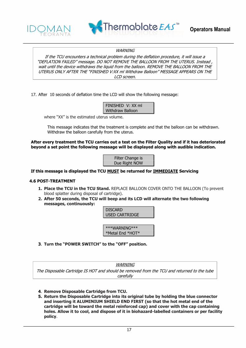
17. After 10 seconds of deflation time the LCD will show the following message:
FINISHED V: XX ml
Withdraw Balloon
where ―XX‖ is the estimated uterus volume.
This message indicates that the treatment is complete and that the balloon can be withdrawn. Withdraw the balloon carefully from the uterus.
After every treatment the TCU carries out a test on the Filter Quality and if it has deteriorated beyond a set point the following message will be displayed along with audible indication.
Filter Change is
Due Right NOW
If this message is displayed the TCU MUST be returned for IMMEDIATE Servicing
4.6 POST-TREATMENT
1. Place the TCU in the TCU Stand. REPLACE BALLOON COVER ONTO THE BALLOON (To prevent blood splatter during disposal of cartridge).
2. After 50 seconds, the TCU will beep and its LCD will alternate the two following messages, continuously:
DISCARD
USED CARTRIDGE
***WARNING***
*Metal End *HOT*
3. Turn the “POWER SWITCH” to the “OFF” position.
WARNING
The Disposable Cartridge IS HOT and should be removed from the TCU and returned to the tube carefully
4. Remove Disposable Cartridge from TCU.
5. Return the Disposable Cartridge into its original tube by holding the blue connector
and inserting it ALUMINIUM SHIELD END FIRST (so that the hot metal end of the cartridge will be toward the metal reinforced cap) and cover with the cap containing
holes. Allow it to cool, and dispose of it in biohazard-labelled containers or per facility policy.
Operators Manual
18
WARNING
The Disposable Cartridge is a SINGLE-USE component. Do not reuse it as this could result in serious injuries to the patient and/or the user.
6. Post treatment hysteroscopy is recommended.
7. Repeat balloon ablations are contraindicated.
5. CLEANING, MAINTENANCE, STORAGE AND TRANSPORTATION
5.1 CLEANING
After each use, the TCU must be cleaned according to the following validated infection control
procedure.
1. Disconnect the TCU from the power supply.
2. Wipe down the outside of TCU housing with warm water using a soft bristle brush until no soilage can
be seen. DO NOT SOAK OR IMMERSE
3. Subsequently, wipe down the outside of the TCU housing with warm water using a clean wipe.
DO NOT SOAK OR IMMERSE.
4. Disinfect the outside of the TCU housing with a clean wipe and 50%IPA/ water solution. DO NOT
SOAK OR IMMERSE.
CAUTION
This unit contains electronic components. DO NOT soak, flush, spray or use excessive free liquid on the TCU. Any units that have been subjected to excessive free liquids during operation or cleaning should not be used and must be returned to Idoman.
5.2 MAINTENANCE
There are no user serviceable parts within the TCU. Opening the device will void the
warranty. Return unit to Idoman for service and repair.
It is recommended that the TCU and its accompanying power supply are subjected to annual inspection
to ensure the safety of the device for both patient and user.
This inspection should include the following:
Power connecting cords and power supply for signs of damage or wear.
TCU housing for signs of damage which may leave it in an unsafe or contaminated state.
Presence and legibility of all Safety related markings and Labels.
Copy of Equipment Operators manual present.
Testing (If Required)
Protective earth resistance
Equipment leakage current
Patient leakage current
Insulation resistance.
Functional Test of Device

Operators Manual
19
All TCU units that have reached their end of service life should be returned to manufacturer for disposable as per WEEE Directive 2002/96/EC
5.3 STORAGE AND TRANSPORT
1. Store the TCU in the Carrying Case. The storage temperature should never exceed 50°C.
2. Store Disposable Cartridge in dry place at room temperature..
3. For storage and transport environmental conditions, see the label with graphical representations and
Technical Specifications table, below.
WARNING
No modification of this equipment is allowed. Unauthorised modifications or access
may result in electrical shock or leave the unit in a hazardous condition.

Operators Manual
20
6. TECHNICAL INFORMATION
6.1. TECHNICAL SPECIFICATIONS
Item Specification
Temperature of treatment liquid during ablation
Initial: 150°C, approx.; Final: 110°C, approx
Treatment pressure 220 mmHg
Heat-up time 20 minutes maximum
Treatment time Less than 3 minutes
Maximum stand-by time in ―Ready‖ state
35 minutes
Input power requirements to regulated power supply
Input Voltage 100-240VAC 50/60HZ Input Power 4-2A
Output power of regulated power supply
24 volts, 6 Amp
Environmental Conditions for Operation
Indoor Use only Temperature is between +10°C and +30°C. Humidity is between 15% and 70%.
Atmospheric pressure between +690 hPa and +1060 hPa.
Environmental Conditions for Storage and Transport
Temperature is between -25°C and +50°C Humidity is between 10% and 90%. Atmospheric pressure is between +500 hPa and +1060 hPa. Tested for transportation in accordance with ASTM 4619-09 Pollution Degree 2 Ultraviolet Protection: Indoor use only
Handling Fragile - Medical devices
Classification TCU Degree of protection Electrical Equipment Class II ME Disposable Cartridge is Type BF Applied Part
Mode of Operation Continuous Operation following cleaning / disinfection. Disposable Cartridge is for Single Use Only
Device Lifetime TCU Software requires manufacturer maintenance after 600 procedures. The Disposable Cartridge is for SINGLE USE ONLY and has a shelf life of 2 Years.
Physical Dimensions
TCU
Length 27,1 cm (27,18cm) Width 8,9 cm (8,89cm)
Height 10,5 cm (10,49cm)
Disposable Cartridge
Total Length 31,3cm (31,24cm) Connector Height 5,5cm (5,59 cm)
Connector Width 5,5cm (5,59 cm)
Insertion Length 12 cm (11,99 cm) From insertion stop to balloon tip maximum
Weight TCU Less than 1Kg
Disposable Cartridge 110g (4oz)
Protection The TCU does not have any degree of protection against direct and prolonged ingress of liquids and should be handled accordingly
THE THERMABLATE EAS DEVICE IS NOT SUITABLE FOR USE IN AN OXYGEN RICH OR HAZARDOUS
SUBSTANCES ENVIRONMENT.
Operators Manual
21
6.2. STANDARDS
The Thermablate EAS device complies with:
IEC60601-1:2005 Edition 3.0 Medical Electrical Equipment, Part 1, General Requirements for Safety
IEC60601-1-2:2007, IEC60601-1-2:2001, IEC60601-1-2:1993 Medical Directive Emissions and
Immunity Standard.
CAN/CSA C22.2 No. 60601.1:08 (with Supplement 1:1994 & Amendment 2:1998) Medical Electrical
Equipment, Part 1, General Requirements for Safety.
ANSI/AAMI ES60601-1:2005 Medical electrical equipment—Part 1: General requirements for basic
safety and essential performance
Guidance and manufacturer’s declaration-electromagnetic emissions
The Thermablate EAS Treatment Control Unit (TCU) is intended for use in the electromagnetic environment specified below. The customer or the user of the Thermablate EAS Treatment Control Unit (TCU) should assure that it is used in such an environment.
Emissions test Compliance Electromagnetic environment - guidance
RF emissions CSPR 11
Group 1 The Thermablate EAS Treatment Control Unit (TCU) uses RF energy only for its internal function. Therefore, its RF emissions are very low and are not likely to cause any interference in nearby electronic equipment
RF emissions CSPR 11 Class A The Thermablate EAS Treatment Control Unit (TCU) is suitable for use in all establishments other than domestic, and may be used in domestic establishments and those directly connected to the public low-voltage power supply network that supplies buildings used for domestic purposes, provided the following warning is heeded.
Warning: This equipment/system is intended for use by healthcare professionals only. This equipment /system may cause radio interference or may disrupt the operation of nearby equipment. It may be necessary to take mitigation measures, such as re-orientating or relocating the Thermablate EAS Treatment Control Unit (TCU) or shielding the location.
Harmonic Emissions IEC 61000-3-2
Class A
Voltage fluctuations / flicker emissions
IEC 61000-3-3
Complies
Operators Manual
22
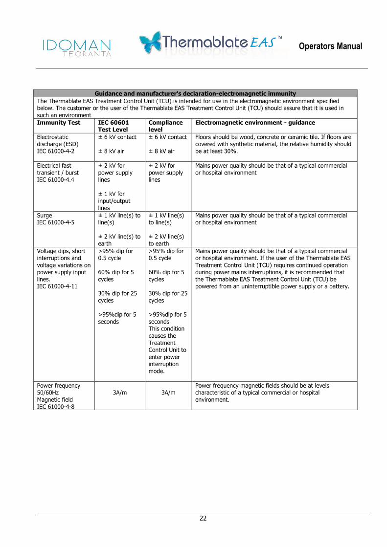
Guidance and manufacturer’s declaration-electromagnetic immunity
The Thermablate EAS Treatment Control Unit (TCU) is intended for use in the electromagnetic environment specified below. The customer or the user of the Thermablate EAS Treatment Control Unit (TCU) should assure that it is used in such an environment
Immunity Test IEC 60601 Test Level
Compliance level
Electromagnetic environment - guidance
Electrostatic discharge (ESD)
IEC 61000-4-2
± 6 kV contact
± 8 kV air
± 6 kV contact
± 8 kV air
Floors should be wood, concrete or ceramic tile. If floors are covered with synthetic material, the relative humidity should
be at least 30%.
Electrical fast transient / burst IEC 61000-4.4
± 2 kV for power supply lines ± 1 kV for input/output lines
± 2 kV for power supply lines
Mains power quality should be that of a typical commercial or hospital environment
Surge IEC 61000-4-5
± 1 kV line(s) to line(s) ± 2 kV line(s) to earth
± 1 kV line(s) to line(s) ± 2 kV line(s) to earth
Mains power quality should be that of a typical commercial or hospital environment
Voltage dips, short interruptions and voltage variations on power supply input lines. IEC 61000-4-11
>95% dip for 0.5 cycle 60% dip for 5 cycles 30% dip for 25 cycles >95%dip for 5 seconds
>95% dip for 0.5 cycle 60% dip for 5 cycles 30% dip for 25 cycles >95%dip for 5 seconds This condition causes the Treatment Control Unit to enter power interruption mode.
Mains power quality should be that of a typical commercial or hospital environment. If the user of the Thermablate EAS Treatment Control Unit (TCU) requires continued operation during power mains interruptions, it is recommended that the Thermablate EAS Treatment Control Unit (TCU) be powered from an uninterruptible power supply or a battery.
Power frequency 50/60Hz Magnetic field IEC 61000-4-8
3A/m
3A/m
Power frequency magnetic fields should be at levels characteristic of a typical commercial or hospital environment.

Operators Manual
23
Guidance and manufacturer’s declaration-electromagnetic immunity
The Thermablate EAS Treatment Control Unit (TCU) is intended for use in the electromagnetic environment specified below. The customer or the user of the Thermablate EAS Treatment Control Unit (TCU) should assure that it is used in such an environment
Immunity Test IEC 60601 Test Level
Compliance level Electromagnetic environment - guidance
Conducted RF IEC 61000-4-6 Radiated RF IEC 61000-4-3
3 Vrms 150 kHz to 80 MHz 3 V/m 80 MHz to 2.5 GHz
3 Vrms
3V/m
Portable and mobile RF communications equipment should be used no closer to any part of the Thermablate EAS Treatment Control Unit (TCU), including cables, than the recommended
separation distance calculated from the equation applicable to the frequency of the transmitter. Recommended separation distance
d=1.2√P
d=1.2√P 80 MHz to 800 MHz
d=2.3√P 800 MHz to 2.5 GHz Where P is the maximum output power rating of the transmitter in watts (W) according to the transmitter manufacturer and d is the recommended separation distance in meters (m). Field strengths from fixed RF transmitters, are determined by an electromagnetic site survey,¹ should be less than the compliance level in each frequency range. ² Interference may occur in the vicinity of equipment marked with the following symbol.
NOTE 1. At 80 MHz and 800 MHz, the higher frequency range applies. NOTE 2. These guidelines may not apply in all situations. Electromagnetic propagation is affected by absorption and reflection from structures, objects and people.
¹. Field strengths from fixed transmitters, such as base stations for radio (cellular/cordless) telephones and land mobile radios, amateur radio, AM and FM radio broadcast and TV broadcast cannot be predicted theoretically with accuracy. To assess the electromagnetic environment due to fixed RF transmitters, an electromagnetic site survey should be considered. If the measured field strength in the location in which the Thermablate EAS Treatment Control Unit (TCU) is used exceeds the applicable RF compliance level above, the Thermablate EAS Treatment Control Unit (TCU) should be observed to verify normal operation. If abnormal performance is observed, additional measures may
be necessary, such as re-orienting or relocating the Thermablate EAS Treatment Control Unit (TCU).
². Over the frequency range 150 kHz to 80 MHz, field strengths should be less than 3 V/m

Operators Manual
24
Recommended separation distances between portable and mobile RF communications equipment and the Thermablate EAS Treatment Control Unit (TCU)
The Thermablate EAS Treatment Control Unit (TCU) is intended for use in the electromagnetic environment in which radiated RF disturbances are controlled. The customer or the user of the Thermablate EAS Treatment Control Unit (TCU) can help prevent electromagnetic interference by maintaining a minimum distance between portables and mobile RF communications equipment (transmitters) and the Thermablate EAS Treatment Control Unit (TCU). As recommended below, according to the maximum output power of the communication equipment.
Rated Maximum output power of transmitter
W
Seperation distance according to frequency of transmitter
150 kHz to 80 MHz d=1.2√P
80 MHz to 800 MHz d=1.2√P
800 MHz to 2.5 GHz d=2.3√P
0.01 0.12 0.12 0.23
0.1 0.38 0.38 0.73
1 1.2 1.2 2.3
10 3.8 3.8 7.3
100 12 12 23
For transmitters rated at a maximum output power not listed above, the recommended separation distance d in meters (m) can be estimated using the equation applicable to the frequency of the transmitter, where P is the maximum output power rating of the transmitter in watts (W) according to the transmitter manufacturer. NOTE 1 At 80 MHz and 800 MHz, the separation distance for the higher frequency range applies. NOTE 2 These guidelines may not apply in all situations. Electromagnetic propagation is affected by absorption and reflection from structures, objects and people

Operators Manual
25
7. ERROR MESSAGES AND TROUBLESHOOTING
During either the warm-up or the treatment cycles, the TCU may issue an error message on the LCD, due
to either a malfunction or incorrect use of the device. The following list indicates the types of errors that
the unit may issue, and the corresponding corrective actions to be taken:
WARNING
If any of the following errors occur during the treatment cycle, the treatment is considered as failed. It is CONTRAINDICATED TO RE-TREAT a patient with the Thermablate EAS device, as
unintended burn may occur. Except as noted.
Error No.
Hardware Failure Corrective Action
1 Ambient temperature sensor
failure (output shorted to +5V)
Unit requires repairing.
2 Ambient temperature sensor failure (output shorted to ground)
Unit requires repairing.
3 Ambient temperature is too high If the error occurs before starting the treatment cycle:
• Turn TCU off and wait until room cools down below 40°C or perform the treatment in an A/C-equipped room.
• Restart the unit and proceed with treatment as indicated.
4 Liquid temperature thermocouple failure
Unit requires repairing.
5 Heater temperature thermocouple
failure
Unit requires repairing.
6 Heaters connection failure Unit requires repairing.
7 Heater overheated • Turn TCU off.
• Wait for 30-40 minutes. • Restart TCU.
8 Pressure sensor failure If the error occurs before starting the treatment cycle:
Unit requires repairing. If the error occurs during the treatment cycle:
• Wait for the unit to withdraw the liquid from the balloon.
• Remove the balloon from the patient only when the unit indicates to do so.
9 Positive overpressure • Wait for the unit to withdraw the liquid from the balloon.
• Remove the balloon from the patient only when the unit indicates to do so.

Operators Manual
26
Error
No. Hardware Failure Corrective Action
10 Negative overpressure If the error occurs before starting the treatment cycle: Restart the unit.
If the error occurs after treatment cycle completion:
• DO NOT REMOVE BALLOON FROM PATIENT. Instead, restart TCU.
• If the error occurs again, turn the TCU off and withdraw the balloon quickly but carefully since some liquid may still be
contained in the balloon. • If the error DOES NOT occur again, wait for the unit to
withdraw the liquid from the balloon, and remove the balloon
from the patient only when the unit indicates to do so.
11 Pump cannot reach test vacuum value
• Turn the unit off. • Ensure the cartridge is properly installed in the TCU, and the
O-Ring is in good condition and properly installed. • Restart the unit.
• If the problem persists fit disposable in second TCU, (if available).
If error occurs again then replace disposable cartridge.
If error does not occur again, original unit may require
servicing.
12 ADC channel 8 is not grounded Unit requires repairing.
13 Liquid temperature does not rise monotonically
Unit requires repairing.
14 Overtime for HEATING state • Restart the unit, proceed with treatment as indicated.
• If error persists, unit requires repairing.
15 Wrong air flow direction during treatment cycles
Unit requires repairing
16 Unable to hold vacuum If the error occurs before starting the treatment cycle:
• Turn the unit off. • Ensure the cartridge is properly installed in the TCU, and the
O-Ring is in good condition and properly installed. • Restart the unit.
• If the problem persists, turn the unit off, replace the cartridge with a new one, and restart the unit.
If the error occurs after treatment cycle completion:
• Turn the TCU off and withdraw the balloon quickly but carefully since some liquid may still be contained in the
balloon. 17 Unable to reach vacuum for balloon
leak tests
• Turn the unit off.
• Ensure the cartridge is properly installed in the TCU, and the
O-Ring is in good condition and properly installed. • Restart the unit.
• If the problem persists, turn the unit off, replace cartridge with a new one, and restart the unit.
NOTE: At the time the second balloon leak test is performed the balloon has already been inserted into the uterus, but actual ablation HAS NOT commenced. It is thus safe to attempt the treatment again.
18 Unable to reach and hold vacuum
during liquid removal
Turn the TCU off and withdraw the balloon quickly but carefully
since some liquid may still be contained in the balloon.

Operators Manual
27
Error
No. Hardware Failure Corrective Action
19 First leak test failure Possible leak in the balloon. Ensure the cartridge is properly
installed in the TCU, and the O-Ring is in good condition and
properly installed. If the problem persists fit disposable in second TCU (if available).
If error occurs again then replace disposable cartridge. If error does not occur again, original unit may require servicing.
20 Second leak test failure Possible leak in the balloon. Replace cartridge with new one,
and restart the unit. NOTE: At the time this balloon leak test is performed the
balloon has already been inserted into the uterus, but actual
ablation HAS NOT commenced. It is thus safe to attempt the treatment again.
21 Comparative leak test failure Possible leak in the balloon. Replace cartridge with new one,
and restart the unit. NOTE: At the time this balloon leak test is performed the
balloon has already been inserted into the uterus, but actual ablation HAS NOT commenced. It is thus safe to attempt the
treatment again.
22 Time out for reaching positive
pressure
If the error occurs before starting the treatment cycle:
• Wait for the unit to withdraw the liquid from the balloon. • Remove the balloon from the patient only when the unit
indicates to do so.
24 Liquid temperature is too low • Restart the unit. Initiate treatment as soon as the unit displays the ―Ready for Treatment‖ message.
• If the problem persists, turn the unit off, replace cartridge with a new one, and restart the unit.
25 Liquid temperature is too high • Turn the unit off.
• CAREFULLY remove cartridge from TCU and allow it to cool down for 30-40 minutes.
• Install cartridge back into TCU.
• Restart the unit and initiate the treatment as soon as the unit displays the ―Ready for Treatment‖ message.
• If the problem persists, turn the unit off, replace cartridge with a new one, and restart again.
26 Value read from RAM cell do not
match that was stored
The unit requires repairing.
27 Data stack overflow The unit requires repairing.

Operators Manual
28
8. LIMITED WARRANTY
IDOMAN TEORANTA warrants to the original purchaser that the Thermablate™ EAS™ TCU and all
accessories provided with it (collectively, the ―Thermablate‖) will be free from defects in material and
workmanship for two (2) years from the date of the original purchase from an Idoman Teoranta authorized
reseller. This limited warranty is nontransferable. If the Thermablate is defective during the warranty
period, the purchaser’s sole and exclusive remedy, and Idoman Teoranta’s sole obligation, will be to (at
Idoman Teoranta’s option): repair the Thermablate to conform with its specifications; replace the
Thermablate with a comparable product; or refund to the purchaser the original purchase price paid for
the Thermablate. Repaired or replaced products or parts may be new or reconditioned, and are subject to
this limited warranty through the end of the original warranty period. To obtain warranty service, the
purchaser must: contact Idoman Teoranta during the warranty period; provide Idoman Teoranta with a
dated proof of original purchase from an Idoman Teoranta-authorized reseller; and ship the Thermablate
to Idoman Teoranta by prepaid delivery and packaged appropriately for safe shipment. The purchaser is
responsible for shipping costs. This warranty does not apply if the defect or malfunction in the
Thermablate was caused by misuse, neglect, unauthorized attempts to open, repair or modify the
Thermablate, use of the Thermablate with accessories or other products that are not authorized by
Idoman Teoranta, or any cause other than the intended normal use of the Thermablate. Non-warranty
work is charged at the minimum repair rate effective at the time the Thermablate is returned to Idoman
Teoranta, repairs include a complete functional test using factory test fixtures.
EXCLUSIONS: TO THE FULL EXTENT ALLOWED BY LAW, THIS LIMITED WARRANTY IS THE PURCHASER’S
SOLE AND EXCLUSIVE REMEDY, AND NO OTHER WARRANTIES, CONDITIONS OR GUARANTEES OF ANY KIND SHALL APPLY, WHETHER STATUTORY, WRITTEN, ORAL, EXPRESS OR IMPLIED, INCLUDING
WITHOUT LIMITATION WARRANTIES, CONDITIONS OR GUARANTEES OF MERCHANTABILITY, FITNESS
FOR A PARTICULAR PURPOSE, PERFORMANCE, QUALITY, OR DURABILITY, ALL OF WHICH ARE DISCLAIMED. IN NO EVENT WILL IDOMAN TEORANTA BE LIABLE FOR ANY SPECIAL, EXTRAORDINARY,
INDIRECT OR CONSEQUENTIAL DAMAGES OF ANY KIND WHATSOEVER, INCLUDING WITHOUT LIMITATION DAMAGES FOR LOSS OF DATA, LOST PROFITS, LOSS OF OPPORTUNITY, BUSINESS
INTERRUPTION, PERSONAL INJURY OR DEATH, OR ANY OTHER LOSS ARISING OUT OF, RELATING TO, OR IN CONNECTION WITH, THE THERMABLATE, EVEN IF IDOMAN TEORANTA IS ADVISED OF THE
POSSIBILITY OF SUCH DAMAGES.
LIABILITY LIMITATIONS:IF, AS A RESULT OF OR IN CONNECTION WITH ANY USE OF THE
THERMABLATE,IDOMAN TEORANTA BECOMES LIABLE TO THE PURCHASER OR ANY OTHER PERSON FOR
ANY DAMAGES, LOSSES, COSTS, EXPENSES, OR OTHER LIABILITIES WHATSOEVER, AND REGARDLESS
OF THE FORM OF ACTION (IN CONTRACT, TORT OR PURSUANT TO STATUTE), THEN IDOMAN
TEORANTA’s AGGREGATE LIABILITY TO ALL SUCH PERSONS WILL BE LIMITED TO AN AMOUNT EQUAL
TO THE PURCHASE PRICE PAID FOR THE THERMABLATE.
The exclusion of certain conditions and warranties and the limitation of certain liabilities is prohibited in some jurisdictions, so these limitations and exclusions may not apply to some purchasers.
Operators Manual
29
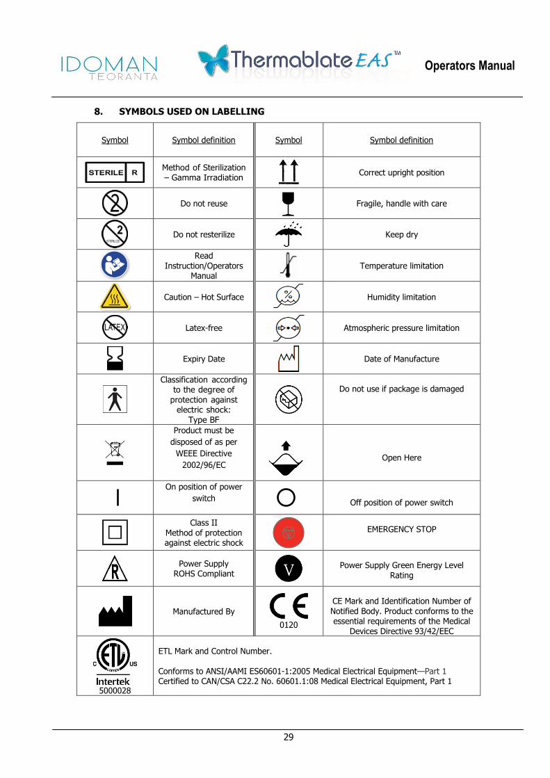
8. SYMBOLS USED ON LABELLING
Symbol Symbol definition Symbol Symbol definition
Method of Sterilization – Gamma Irradiation
Correct upright position
Do not reuse
Fragile, handle with care
Do not resterilize
Keep dry
Read Instruction/Operators
Manual
Temperature limitation
Caution – Hot Surface
Humidity limitation
Latex-free
Atmospheric pressure limitation
Expiry Date
Date of Manufacture
Classification according to the degree of
protection against electric shock:
Type BF
Do not use if package is damaged
Product must be
disposed of as per
WEEE Directive
2002/96/EC
Open Here
On position of power
switch
Off position of power switch
Class II Method of protection against electric shock
EMERGENCY STOP
Power Supply ROHS Compliant
Power Supply Green Energy Level Rating
Manufactured By
0120
CE Mark and Identification Number of Notified Body. Product conforms to the essential requirements of the Medical
Devices Directive 93/42/EEC
5000028
ETL Mark and Control Number. Conforms to ANSI/AAMI ES60601-1:2005 Medical Electrical Equipment—Part 1 Certified to CAN/CSA C22.2 No. 60601.1:08 Medical Electrical Equipment, Part 1

Operators Manual
30
Idoman Teoranta
Killateeaun,
Tourmakeady,
Co Mayo
Ireland
Tel No: +353 94 95 44726
Fax No: +353 94 95 44725
E-mail: [email protected]
Web Site: www.idoman-med.com
0120
Distributed by: Place Distributor’s
Label Here

Operators Manual
31
10. NOTES:

Operators Manual
32
DISTRIBUTORS :
Thermablate EAS, Endometrial Ablation System
Copyright © 2016 by Idoman Teoranta All rights reserved.
logos are trademark of IDOMAN Teoranta
AND