Therapeutic Modalities
26
CHAPTER 10 THE RAPEUTIC MODALITIES Jo hn Carlos , J r. I. Superficial Thermotherapy A. Physics Related to Heat Transmission I. Conduction: heat transfer from a warmer object to a cooler object through direct molecular interaction of objects in physical contact. Conductive modalities: hot packs, paraffin. 2. Convection: heat transfer by movement of air or fluid from a warmer area to a cooler area or movin o b past a cooler body part. Convective modalities: whirlpool, Hubbard tank, fluidotherapy. 3. Radiation: transfer of heat from a warmer object to a cooler object through the transmission of elec- tromagnetic energy without heating an intervening medium. Infrared waves absorbed by cooler body. Radiation modality: infrared lamp. B. Physiological Effects of General Heat Application Large areas of the body surface area exposed to heat modality; e.g., whirlpool (hip and knee immersed) and Hubbard tank (lower extremities and trunk immersed) (Table 10-1). C. Physiological Effects of Small Surface Area Heat Application Heat modality applied to discrete area of body; e.g. , low back, hamstring, neck. I. Body tissue responses to superficial heat. a. Skin temperature rises rapidly and exhibits greatest temperature change. b. Subcutaneous tissue temperature rises less rap- idly and exhibits smaller change. c. Muscle and joint show least temperature change, if any, depending on size of structure. 2. Physiological effects on body systems and struc- tures to small surface area heat modalities are list- ed in Tables 10-2 and 10-3. D. Goals and Indications for Superficial Thermotherapy I. Modulate pain; increase connective tissue extensi- bility; reduce or eliminate soft tissue inflammation and swelling; accelerate the rate of tissue healing; reduce or eliminate soft tissue and joint restriction and muscle spasm. 2. Preparation for electrical stimulation; massage; passive and active exercise. E. Precautions for Use of Superficial Thermotherap y I. Cardiac insufficiency; edema; impaired circula- tion; impaired thermal regulation; metal in treat- ment site and open wounds. TABL E 10-1 - PHYSI OLOGICAL EFFECTS O F GE NERAL HEAT APPLICATION INCREASED Cardiac output Metabolic rate Pulse rate Respiratory rate Vasodilation DECREASED Blood pressure Muscle activity (sedentary effect) Blood to internal organs Blood flow to resting muscle Stroke volume
-
Upload
placinta-andreea -
Category
Documents
-
view
85 -
download
1
Transcript of Therapeutic Modalities

CHAPTER 10
THERAPEUTIC MODALITIES Jo hn Carlos, Jr.
I. Superficial Thermotherapy A. Physics Related to Heat Transmission
I. Conduction: heat transfer from a warmer object to a cooler object through direct molecular interaction of objects in physical contact. Conductive modalities: hot packs, paraffin.
2. Convection: heat transfer by movement of air or fluid from a warmer area to a cooler area or movino
b
past a cooler body part. Convective modalities: whirlpool, Hubbard tank, fluidotherapy.
3. Radiation: transfer of heat from a warmer object to a cooler object through the transmission of electromagnetic energy without heating an intervening medium. Infrared waves absorbed by cooler body. Radiation modality: infrared lamp.
B. Physiological Effects of General Heat Application Large areas of the body surface area exposed to heat modality; e.g. , whirlpool (hip and knee immersed) and Hubbard tank (lower extremities and trunk immersed) (Table 10-1).
C. Physiological Effects of Small Surface Area Heat Application Heat modality applied to discrete area of body; e.g. , low back, hamstring, neck. I. Body tissue responses to superficial heat.
a. Skin temperature rises rapidly and exhibits greatest temperature change.
b. Subcutaneous tissue temperature rises less rapidly and exhibits smaller change.
c. Muscle and joint show least temperature change, if any, depending on size of structure.
2. Physiological effects on body systems and structures to small surface area heat modalities are listed in Tables 10-2 and 10-3.
D. Goals and Indications for Superficial Thermotherapy I. Modulate pain; increase connective tissue extensi
bility; reduce or eliminate soft tissue inflammation and swelling; accelerate the rate of tissue healing; reduce or eliminate soft tissue and joint restriction and muscle spasm.
2. Preparation for electrical stimulation; massage; passive and active exercise.
E. Precautions for Use of Superficial Thermotherapy I. Cardiac insufficiency; edema; impaired circula
tion; impaired thermal regulation; metal in treatment site and open wounds.
TABLE 10-1 - PHYSIOLOGICAL EFFECTS O F GENERAL H EAT APPLICATION
INCREASED
Cardiac output
Metabolic rate
Pulse rate
Respiratory rate
Vasodilation
DECREASED
Blood pressure
Muscle activity (sedentary effect)
Blood to internal organs
Blood flow to resting muscle
Stroke volume

294
F. Contraindications to the Use of Superficial Thermotherapy I. Acute and early subacute traumatic and inflamma
tory conditions, decreased circulation, decreased sensation, deep vein thrombophlebitis, impaired cognitive function , malignant tumors, tendency toward hemorrhage or edema, very young and very old patients. Additional contraindications relative to specific modality listed separately.
G. General Treatment Preparation for Thermotherapy and Cryotherapy I . The application of physical agents must be per
formed by a qualified physical therapist or personnel supervised by a physical therapist (physical therapist assistant, affiliating physical therapist or physical therapist assistant student). The treatment and expected sensations must be explained to the patient.
2. Place patient in comfortable position. 3. Expose treatment area and drape patient properly. 4. Inspect skin and check temperature sensation prior
to treatment. 5. If patient has good cognitive function, a call bell or
other signaling device can be given to patient to
alert personnel of any untoward effects of treatment. Check patient frequently during initial treatment. A patient with impaired cognitive function, such as Alzheimer's disease, senility or mental retardation, should be checked frequently (every five minutes) during treatment.
6. Dry and inspect skin at conclusion of treatment. 7. Specific procedures for each physical agent listed
separately. H. Superficial Heating Physical Agents
1. Hot packs. a. Description: a canvas pack filled with silica gel
which is heated by immersing in water between 165° -170°P'
b. Method of heat transmission: conduction. c. Method of application.
(1) Place pack(s) into terry cloth cover. Place one folded towel between patient and pack for hygienic purposes. (a) One towel method:
• Fold four towels in half, width-wise. • Place each towel on top of the other,
forming eight layers of toweling. • Place towels on treatment area.
TABLE 10-2 - INCREASED PHYSIOLOGICAL RESPONSES OF BODY SYSTEMS AND STRUCTURES TO LOCAL HEAT APPLICATION
SYSTEMISTRUCTURE MECHANISM
a. Blood flow Dilation of arteries and arterioles
b. Capillary permeability Increase in capillary pressure
c. Elasticity of nonelastic tissues Increased extensibility of collagen tissue
d. Metabolism For every 10°C increase in tissue temperature there is a two-threefold increase rate of cellular oxidation (Van't Hoff's Law)
e. Vasodilation Activation of axon reflex and spinal cord reflex, release of vasoactive agents (bradykinin, histamine, prostaglandin)
f. Edema Increased capillary permeability
TABLE 10-3 - DECREASED PHYSIOLOGICAL RESPONSES OF BODY SYSTEMS AND STRUCTURES TO LOCAL HEAT APPLICATION
SYSTEMISTRUCTURE MECHANISM
a. Joint stiffness
b. Muscle strength
c. Muscle spasm
d. Pain
Increased extensibility of collagen tissue and decreased viscosity
Decreased function of glycolytic process
Decreased firing of II afferents of muscle spindle and increased firing of Ib GTO fibers reduces alpha motor neuron activity and thus decreases tonic extrafusal activity
Presynaptic inhibition of A delta and C fibers via activation of A beta fibers (Gate Theory), disruption of pain-spasm cycle

o Place pack on towels and cover pack with folded towel to retard heat loss.
(b) Two-towel wrap method: o Fold two towels lengthwise and
place one perpendicular over the other, forming a cross.
o Place pack in the center of the towels. o Fold the ends of the towels over the
pack, forming eight layers of toweling on top of the pack. Invert pack placing the eight layers of toweling on patient.
(2) Place pack on patient. If patient must be placed on pack, use additional towels and pillows to support patient. This will minimize discomfort or excessive heating of treatment area due to weight of patient on pack.
(3) Secure the pack to the patient with towels, sandbags or straps, if needed.
(4) Cover pack with folded towel to retard heat loss.
(S) Physical therapist or physical therapist assistant should check the skin periodically during treatment.
d. Temperature of the water bath: 16so-170°F. e. Treatment time: 20-30 minutes. f. Indications/contraindications: refer to sections I,
D, E, and F. 2. Paraffin bath. Therapeutic application of liquid
paraffin to a body part for the transmission of heat. Paraffin bath is a thermostatically controlled unit that contains a paraffin wax and mineral oil mixture in a 6: 1 or 7: I ratio. The paraffin/mineral oil mixture melts between 118°F-130°F and is normally self-sterilizing at temperatures of 17S-180 degrees F. Paraffin is primarily applied to small, irregularly-shaped areas such as the wrist, hand and foot. a. Method of heat transmission: conduction. b. Procedure.
(1) Glove method (dip and wrap). (a) Remove jewelry or cover jewelry with
several layers of gauze, if jewelry cannot be removed.
(b) Wash the part and check for infection and open areas.
(c) The part is dipped several times to apply six to twelve layers of paraffin.
(d) Mter the paraffin has solidified, the part is wrapped with plastic wrap or waxed
Therapeutic Modalities 295
paper, and covered with several layers of toweling and secured with tape or rubber bands.
(e) The patient places the part in a comfortable or elevated position for IS-20 minutes.
(2) Dip and immersion method: the procedure follows steps (a) - (c) above, except the part remains comfortably in the bath after the fmal dip.
c. Treatment temperature: 12S-127°F. d. Treatment time: IS-20 minutes. e. Indications: painful joints due to arthritis or other
inflammatory conditions in the late subacute or chronic phase, joint stiffness. Most often used on wrists and hands.
f. Contraindications: allergic rash, open wounds, recent scars and sutures, skin infections.
3. Fluidotherapy is no longer tested on the NPTE. 4. Infrared lamp is no longer tested on the NPTE. S. Hydrotherapy (whirlpool and Hubbard tank).
Description: partial or total immersion baths in which the water is agitated and mixed with air to be directed against or around the affected part. Patients can move the extremities easily due to the buoyancy and therapeutic effect of the water. a. Method of heat transmission: convection. b. Physics related to hydrotherapy.
(1) Specific heat is the heat-absorbing capacity of water. The amount of heat a gram of water absorbs or gives off in changing the temperature one degree centigrade. The specific heat of water is about four times that of air.
(2) Thermal conductivity is the capability of a liquid, gas or solid to conduct heat.
(3) Buoyancy is the upward force of the water on an immersed or partially immersed body or body part which is equal to the weight of the water that it displaced (Archimedes' Principle).
(4) Viscosity is the ease at which fluid molecules move with respect to one another. High temperature lowers the viscosity of the fluid.
(S) Hydrostatic pressure is the circumferential water pressure exerted on an immersed body part. A pressure gradient is established between the surface water and deeper water due to the increase in water density at deeper levels.

296
(6) Cohesion is the tendency of water molecules to adhere to one another. The resistance encountered while moving through water is partially due to the cohesion of the water molecules and force needed to separate them.
(7) Density of the water is proportional to its depth. Deeper water must support the water above it and is more dense.
c. Method of application: whirlpool. (1) Fill the tank with water to the proper level
and to the desired temperature. Whirlpool liners may be used for patients with burns, wounds, or who are infected with bloodborne pathogens (human immunodeficiency virus or hepatitis-B virus).
(2) Add disinfectant if open wounds are present. Common antibacterial agents: sodium hypochlorite (bleach), dilution of 200 parts per million (ppm); povidone-iodine, dilution of 4 ppm; Chloramine-T, 100-200 ppm.
(3) Standard precautions (gowns, goggles , masks, and gloves) should be applied when working in infected environment, particularly when working with possibility of splashing. (Refer to Table 5-2).
(4) Assist patient in immersing his or her body or body part into the tank.
(5) Pressure points should be padded for patient comfort and to minimize compression of blood vessels and nerves. Keep towels out of water.
(6) Adjust agitator to desired position. (7) Thrn on agitator and adjust the force, direc
tion, depth, and aeration. (8) Monitor patient's response and tolerance to
the whirlpool. (9) At end of treatment, dry and inspect skin.
d. Method of application: Hubbard tank. (1) Fill the tank with water to the proper level
and to the desired temperature. (2) Add disinfectant, if open wounds are present
[refer to section 5c(2)]. (3) Position and secure patient supine on
stretcher or pneumatic lift. (4) Lift patient over edge of tank and slowly
lower to water line to enable patient to get accustomed to the water temperature.
(5) Continue to lower patient into the water with head elevated. Secure head end of stretcher
to bracket in the tank. Remove the suspended hoist when stretcher is resting on bottom of tank or halt descent of lift at desired level.
(6) Turn on agitator and adjust the force, direction, depth, and aeration.
(7) Monitor patient's response and tolerance to the whirlpool.
(8) At end of treatment, remove patient on to stretcher or lift. Dry and inspect skin.
(9) Clean and dry whirlpool. e. Treatment temperature: varies with size and
status of area treated. (1) 103°F-110°F whirlpool. (2) 100°F Hubbard tank. (3) 95°F-100°F peripheral vascular disease. (4) 92°F-96°F open wounds.
f. Treatment time: 20 minutes. Up to 30 minutes, if other therapeutic procedures are also being performed.
g. General cleaning procedures. Procedures may vary in different settings. (1) After draining water from tank, rinse the
entire tank including the openings in agitator and all drains.
(2) Wipe all areas that were in contact with water with a clean dry towel.
(3) Wash the inside of the tank, outside of the agitators and the drains with disinfectant diluted in warm water. Also wash agitators, thermometers and all equipment used in treatment. Some tanks have a hose that can be used to spray tank. Allow disinfectant to stand for at least one minute.
(4) Place agitator in bucket filled with water and disinfectant, covering all openings with solution. Thrn on agitator for about 20-30 seconds. Turn off motor and remove agitator from bucket.
(5) Rinse the entire tank and all equipment until all residue is removed. Following use with patients with wounds or burns, refill the tank with hot water and disinfectant and allow solution to stand for five minutes (with or without agitator).
(6) Repeat step (4) with clean water. You may wish to rinse that tank a second time with hot water (11O°F-1l5°F) to hasten drying.
(7) Wipe both the inside and the outside of the tank dry with a clean towel.
h. Indications: decubitus ulcers, open burns and

wounds, post-hip fractures, post-surgical conditions of hip, subacute and chronic musculoskeletal conditions of neck, shoulders and back, rheumatoid arthritis.
1. Precautions. (1) Decreased temperature sensation; impaired
cognition; recent skin graft; incontinence; confusion/disorientation; decondi tioned state; hydrophobia with full immersion.
j. Contraindications. (1) Bleeding; wound maceration; cardiac insta
bility; profound epilepsy with full immersion.
h. Electrical safety: safety precautions must be taken with any modality that potentially exposes the patient to electrical hazard from faulty electrical connections. (I) A ground fault circuit interrupter should be
installed at the circuit breaker of receptacle of all whirlpools and Hubbard tanks. The electrical circuit is broken if current is diverted to the patient (macroshock) who is grounded rather than to a grounded modality.
(2) All whirlpool turbines, tanks and motors and motors used to lift patients should be checked for current leakage (broken or frayed connections).
6. Nonimmersion irrigation device. a. Small, hand-held electric water pump that pro
duces a water jet to create a shearing force to loosen tissue debris. Some devices produce a pulsed lavage and include suction to remove debris.
b. Procedure. (1) Treatment should take place in an enclosed
area. (2) Face and eye protection, gloves and water
proof gown are required. (3) Sterile, warm saline is used. Antimicrobials
may be added. (4) Select appropriate treatment pressure, usu
ally 4-8 psi. Pressure may be increased in presence of large amounts of necrotic tissue or tough eschar. Pressure should be decreased with bleeding, near a major vessel or if a patient complains of pain.
(5) Treatment time is usually 5-15 minutes, once a day. Wound size and amount of necrotic tissue may increase treatment parameters.
Therapeutic Modalities 297
7. Aquatic Therapy. a. A form of hydrotherapy used primarily for
weightbearing activities, active exercise or horizontal floating activities. Swimming pools or Hubbard tanks with or without walking troughs and treadmill units are used.
b. Principles. (1) Movement horizontal to or upward toward
the water surface (active assistive exercise) is made easier by the buoyancy of the water. A flotation device may be used as well.
(2) Movement downward is more difficult. A flotation device would increase resistance.
(3) Increasing speed of movement increases resistance because of turbulence and cohesion of water. Use of hand-held paddles held width-wise will increase resistance. Streamlining can be achieved by turning the paddle and slicing through the water.
(4) Amount of weightbearing can be determined by the water depth. The greater the depth, the less the load on the extremeties because of buoyancy.
c. Water temperature is 92-98 degrees F. d. Treatment time varies with patient tolerance. e. Open wounds and skin infections must be cov
ered. f. Goals are to improve standing balance: partial
weightbearing ambulation; aerobic exercise; improve ROM; increase muscle strength via active assistive, active or resistive exercise.
g. Contraindications are incontinence; urinary tract infections; severe epilepsy; unprotected open wounds; unstable blood pressure or severe cardiopulmonary dysfunction.
TABLE 10-4 - PHYSIOLOGICAL EFFECTS OF GENERAL COLD APPLICATION
DECREASED
Metabolic rate
Pulse rate
Respiratory rate
Venous blood pressure
INCREASED
Blood flow to internal organs
Cardiac output
Stroke volume
Arterial blood pressure Shivering (occurs when core temperature drops)

298
II. Cryotherapy A. Physics Related to Cryotherapy Energy Transmission
Abstraction is the removal of heat via conduction or evaporation. 1. Conduction: transfer of heat from a warmer object to
a cooler object through direct molecular interaction of objects in physical contact. Conductive modalities: cold pack, ice pack, ice massage, cold bath.
2. Evaporation (heat of vaporization): highly volatile liquids that evaporate rapidly on contact with warm object. Evaporative modality: vapocoolant sprays (Fluori-Methane). Continued use questionable due to environmental concerns.
B. Physiological Effects of Large Surface Area Cold Application (Table 10-4).
C. Physiological Effects of Small Surface Area Cold Application 1. Effects of cold application on body tissues.
a. Skin temperature falls rapidly and exhibits greatest temperature change.
b. Subcutaneous temperature falls less rapidly and displays smaller temperature change.
c. Muscle and joint show least temperature change, requiring longer cold exposure.
2. Vasoconstriction of skin capillaries resulting in blanching of skin in center of contact area and hyperemia due to histamine reaction, around the edge of contact area in normal tissue.
3. Cold-induced vasodilation: cyclic vasoconstriction and vasodilation following prolonged cold exposure (>15 minutes). Occurs mostly in hands, feet and face where arteriovenous anastomoses are found. Called the "hunting" reaction. Recent studies have questioned the clinical significance of this reaction.
4. Physiological effects on body systems and structures to small surface area cold modalities (Tables 10-5 and 10-6).
5. Adverse physiological effects of cold due to hypersensitivity.
TABLE 10-5 - DECREASED PHYSIOLOGICAL RESPONSES OF BODY SYSTEMS AND STRUCTURES TO LOCAL COLD APPLICATION
SYSTEM/STRUCTURE MECHANISM
a. Blood flow Sympathetic adrenergic activity produces vasoconstriction of arteries, arterioles and venules
b. Capillary permeability Decreased fluids into interstitial tissue
c. Elasticity of nonelastic tissues Decreased extensibility of collagen tissue
d. Metabolism Decreased rate of cellular oxidation
e. Muscle spasm Decreased firing of " afferents of muscle spindle, increased firing of Ib GTO fibers reduces alpha motor neuron activity and thus decreases tonic extrafusal activity
f. Muscle strength Decreased blood flow, increase in viscous properties of muscle (long duration: >5-10 min.)
g. Spasticity Decrease in muscle spindle discharge (afferents: primary, secondary), decreased gamma motor neuron activity
h. Vasoactive agents Decreased blood flow
TABLE 10-6 - INCREASED PHYSIOLOGICAL RESPONSES OF BODY SYSTEMS AND STRUCTURES TO LOCAL COLD APPLICATION
SYSTEM/STRUCTURE
a. Joint stiffness
b. Pain threshold
c. Increased blood viscosity
d. Muscle strength
MECHANISM
Decreased extensibility of collagen tissue and increased tissue viscosity
Inhibition of A delta and C fibers via activiaton of A beta fibers (Gate Theory), interruption of pain-spasm cycle, decreased sensory and motor conduction, synaptic transmission slowed or blocked.
Decreased blood flow in small vessels facilitates red blood cells adhering to one another and vessel wall-impeding blood flow.
Facilitation of alpha motor neuron (short duration: 1-5 min)

a. Cold urticaria: erythema of the skin with wheal formation associated with severe itching due to histamine reaction.
b. Facial flush, puffiness of eyelids, respiratory problems and in severe cases, anaphylaxis (decreased blood pressure, increased heart rate) with syncope are also related to histamine release.
D. Goals and Indications for Cryotherapy 1. Modulate pain; reduce or eliminate soft tissue
inflammation or swelling; reduce muscle spasm; reduce spasticity.
E. Precautions 1. Hypertension ; impaired temperature sensation;
open wound; over superficial nerve; very old or young.
F. Contraindications to Use of Cryotherapy 1. Cold hypersensitivity (urticaria); cold intolerance;
cryoglobulinemia; peripheral vascular disease; impaired temperature sensation; Raynoud's disease.
G. Procedures 1. Cold packs. Description: vinyl casing filled with
silica gel or sand-slurry mixture. a. Method of heat transmission: conduction. b. Method of application.
(1) Keep the patient warm throughout treatment. (2) Dampen a towel with warm water, wring
out excessive water, fold in half, width-wise and place cold pack on towel.
(3) Place pack on patient and cover with dry towel to retard warming.
(4) Secure pack. c. Treatment temperature: packs are maintained
in refrigerated unit at O°F-lO°F. d. Treatment time: 10-20 minutes. e. Indications/contraindications: see general infor
mation. 2. Ice packs. Description: crushed ice folded in moist
towel or placed in plastic bag covered by moist towel. a. Method of heat transmission: conduction
(abstraction). b. Method of application.
(I) Apply the ice pack to body part. (2) Cover pack with dry towel.
c. Treatment time: 10-20 minutes. 3. Ice towels. Description: towels soaked in ice slush.
Water is added to shaved ice to produce an ice slush. a. Method of heat transmission: conduction. b. Method of application.
(1) Immerse two towels in slush, wring one out
Therapeutic Modalities 299
and apply to body part. (2) Secure towel manually. (3) Exchange towels when applied towel
warms up, usually in 45-60 seconds. (4) Repeat procedure to reach or maintain effect.
c. Treatment time: 10-15 minutes. 4. Ice massage. Description: ice cylinder formed by
freezing water in a paper cup or styrofoam cup. Salt may be added to create a colder slush mixture. A lollipop stick or wooden tongue depressor may or may not be placed in water during freezing process. During the application of ice massage, the patient will usually experience the following sequence of physiological response stages: cold, burning, aching, and numbness. a. Method of heat transmission: conduction. b. Method of application.
(1) Remove ice from container. Wrap ice with towel or wash cloth, if ice has no lollipop stick. If ice is retained in container, tear off bottom half and hold top half.
(2) Apply the ice massage to an area no larger then 4"x 6" in slow (2"/sec) overlapping circles or overlapping longitudinal strokes, each stroke covering one-half of previous circle or stroke. If treating a large area, divide into smaller areas.
(3) Do not massage over bony area or superficial nerves (e.g., peroneal/fibular).
(4) Use a towel to dab excess water from treatment area. Ice will melt rapidly initially, but rate of melting will slow as skin cools.
(5) Continue treatment until anesthesia is achieved.
c. Treatment time: 5-10 minutes or until analgesia occurs.
5. Vapocoolant spray. Description: a non-toxic, nonflammable volatile liquid which produces rapid cooling when a fme spray is applied to the skin. Vapocoolant sprays are primarily used to reduce muscle spasm, desensitizing trigger points. The use of vapocoolant sprays is being questioned due to the chloroflourocarbon ingredients in the spray and its effect on the environment. a. Method of heat transmission: evaporation. b. Procedure (spray and stretch method).
(1) Invert container, nozzle down, hold about 18"-24" from treatment area.
(2) Spray at 30° angle and sweep spray over treatment at 4"/second.

300
(3) Allow liquid to completely evaporate before applying next sweep. Caution! Do not frost skin.
(4) The muscle should be passively stretched before and during application.
(5) Cover the entire treatment area, starting at the pain site and moving to the area of referred pain.
(6) Have patient perform active exercise after spraying.
c. Treatment time: 10-15 minutes. d. Indications: myofascial referred pain, trigger
points. e. Contraindications: refer to section liF.
6. Contrast baths. Description: the alternating immersion of a body part in warm and cold water to produce a vascular exercise through active vasodilation and vasoconstriction of the blood vessels. The effectiveness of this method in raising deep tissue temperature via increased circulation of deep vessels has been questioned. It may be useful in promoting pain modulation. a. Method of heat transmission: conduction. b. Procedure.
(1) The treatment usually begins in warm (80-110 degrees F) water.
(2) Place part in the warm water for 4 minutes, then transfer to cold water for 1 minute.
(3) Immerse part in warm water for 4 minutes. (4) Continue sequence of 4:1. End in warm
water. (5) The patient's condition may determine the
ending temperature. Ending in cold water may be more beneficial if reducing edema is the goal.
c. Treatment temperature. (1) Hot water: 100°F-110°F. (2) Cold water: 55°F-65°F. (3) During initial treatment you may wish to
begin with the upper end of the cold range and the lower end of the hot range.
d. Treatment time: 20-30 minutes. e. Indications: any condition requiring stimulation
of peripheral circulation in limbs, peripheral vascular disease, sprains, strains, and trauma (after acute condition abates).
f. Contraindications: advanced arteriosclerosis, arterial insufficiency, loss of sensation to heat and cold.
III. Acoustic Radiation: Ultrasound A. Biophysics Related to Ultrasound
1. Conversion: mechanical energy produced by sound waves at frequencies between 85 KHz and 3 MHz and delivered at intensities between 0 and 3 W/cm2 is absorbed by body tissues and changed to thermal energy.
2. Applicator contains a piezoelectric crystal (transducer). a. Transducer converts electrical energy into
acoustical energy via reverse piezoelectric effect. b. Alternating voltage causes mechanical defor
mation of the crystal. c. Crystal resonates (vibration) at current frequency. d. Oscillating crystal produces sound waves with
little dispersion of energy (collimated beam). e. Oscillating sound wave produces radiation or
mechanical pressure waves in the tissue fluid medium. The molecules within the tissue vibrate and the resulting friction produces heat.
3. Transducer size. a. Ultrasound transducers come in a variety of
sizes from 1 cm2 to 10 cm2• 5 cm2 is the most
commonly used. b. Transducer size should be selected relative to
the size of the treatment area (one cm2=wrist; 5cm2=shoulder, leg).
c. Effective radiating area (ERA). (1) The ERA is the area of the faceplate (crys
tal size) which is smaller relative to the soundhead.
4. Spatial characteristics of ultrasound. a. During continuous ultrasound, spatial charac
teristics of ultrasound are predominant. b. Continuous US is applied to achieve thermal
effects (e.g., chronic conditions). c. Ultrasound energy (intensity) is not uniformly
distributed over the surface of the transducer, because the energy is mechanically blocked by the adhesive bonding of the crystal in the transducer and the pressure waves interfere with each other as they radiate from different areas of the crystal.
d. Uneven intensity produces a high level of energy in the center of the ultrasound beam relative to the surrounding areas. This effect produces a "hot spot" (peak spatial intensity) in the beam. Moving the soundhead or using pulsed ultrasound will tend to reduce the effect of the hot spot.
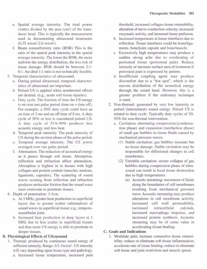
e. Spatial average intensity. The total power (watts) divided by the area (cm2
) of the transducer head. This is typically the measurement used in documenting ultrasound treatments (0.25 w/cml-2.0 w/cm2
).
f. Beam non uniformity ratio (BNR) This is the ratio of the spatial peak intensity to the spatial average intensity. The lower the BNR, the more uniform the energy distribution, the less risk of tissue damage. BNR should be between 2: 1-6:l. An ideal 1:1 ratio is not technically feasible.
5. Temporal characteristics of ultrasound. a. During pulsed ultrasound, temporal character
istics of ultrasound are important. b. Pulsed US is applied when nonthermal effects
are desired. (e.g., acute soft tissue injuries). c. Duty cycle. The fraction of time the US energy
is on over one pulse period (time on + time off). For example, a 20% duty cycle could have an on time of 2 ms and an off time of 8 ms. A duty cycle of 50% or less is considered pulsed US. A duty cycle of 51 %-99% produces less acoustic energy and less heat.
d. Temporal peak intensity. The peak intensity of US during the on-time pha e of the pulse period.
e. Temporal average intensity. The US power averaged over one pulse period.
f. Attenuation. The reduction of acoustical energy as it passes through soft tissue. Absorption, reflection and refraction affect attenuation. Absorption is highest in in tissues with high collagen and protein content (muscles, tendons, ligaments, cap ules). The scattering of sound waves resuting from reflection and refraction produces molecular friction that the sound wave must overcome to penetrate tissues.
6. Depth of penetration: 3-5cm. a. At 3 MHz, greater heat production in superficial
layers due to greater scatter (attenuation) of sound waves in superficial tissue; e.g., temporomandibular joint.
b. Increased heat production in deep layers at 1 MHz due to less scatter in superficial tissues and thus more US energy is able to penetrate to deeper tissues.
B. Physiological Effects of Ultrasound 1. Thermal: produced by continuous sound energy of
sufficient intensity. Range: 0.5-3w/cm2• US intensity
will vary depending upon tissue type and pathology. a. Increased tissue temperature, increased pain
Therapeutic Modalities 301
threshold, increased collagen tissue extensibility, alteration of nerve conduction velocity, increased enzymatic activity, and increased tissue perfusion.
b. Increased temperature at tissue interfaces due to reflection. Tissue interfaces could be bonelligaments, bone/joint capsule and bone/muscle.
c. Excessively high temperatures may produce a sudden strong ache due to overheating of periosteal tissue (periosteal pain). Reduce intensity or increase surface area of treatment if periosteal pain is expressed by patient.
d. Insufficient coupling agent may produce discomfort due to a "hot spot", which is the uneven distribution of the acoustical energy through the sound head. However, this is a greater problem if the stationary technique is used.
2. Non-thermal: generated by very low intensity or pulsed (intermittent) sound energy. Pulsed US is related to duty cycle. Typically duty cycles of 20-50% for non-thermal intervention. a. Cavitation: alternating compression (condensa
tion phase) and expansion (rarefaction phase) of small gas bubbles in tissue fluids caused by mechanical pressure waves. (1) Stable cavitation: gas bubbles resonate but
no tissue damage. Stable cavitation may be responsible for diffusional changes in cell membranes.
(2) Unstable cavitation: severe collapse of gas bubbles during compression phase of ultrasound can result in local tissue destruction due to high temperatures. (a) Acoustic streaming: movement of fluids
along the boundaries of cell membranes resulting from mechanical pressure wave. Acoustic streaming may produce alterations in cell membrane activity, increased cell wall permeability, increased intracellular calcium, increased macrophage response, and increased protein synthesis. Acoustic streaming may be of some value in accelerating tissue healing.
C. Goals and Indications 1. Modulate pain; increase connective tissue extensi
bility; reduce or eliminate soft tissue inflammation; accelerate rate of tissue healing; reduce or eliminate soft tissue and joint restriction and muscle spasm.

302
D. Precautions 1. Acute inflammation; breast implants; open epiphyses
and healing fractures. E. Contraindications
1. Impaired circulation; impaired cognitive function; impaired sensation; thrombophlebitis; joint cement; plastic components; over vital areas such as brain, ear, eye, heart, cervical ganglia; carotid sinuses; reproductive organs; spinal cord; over cardiac pacemakers or pregnant uterus.
F. Procedures 1. Direct contact (transducer/skin interface):
Description: moving sound head in contact with relatively flat body surface. a. Apply generous amount of coupling medium
(geL/cream) to skin. b. US requires a homogenous medium (mineral
oil, water, commercial gel) for effective sound wave transmission and act as a lubricating agent.
c. Select sound head size (ERA one half the size of the treatment area). Place sound head at right angle to skin surface.
d. Move sound head slowly (approx. 1.5H /sec) in overlapping circles or longitudinal strokes maintaining sound head to body surface angle.
e. Each motion covering one-half of previous circle or stroke.
f. Do not cover an area greater than two to three times the size of the effective radiating area (ERA) per five minutes of treatment. To cover an area greater than twice the ERA, apply US in two or more sections.
g. While sound head is moving and in firm contact, turn up intensity to desired level.
h. Treatment intensity: 0.5-2.5 w/cm2 depending on treatment goal. Lower intensities for acute conditions or thin tissue (wrist joint) and for chronic conditions or thick tissue (low back) higher intensities should be considered.
i. Periosteal pain occurring during treatment may be due to high intensity, momentary slowing or cessation of moving head. If this occurs, stop treatment and readjust US intensity or add more coupling agent.
J. Treatment time: 3-10 minutes, depending on size of area, intensity, condition and frequency.
2. Indirect contact (water immersion), use with irregular body parts. a. Fill container with water high enough to cover
treatment area. A plastic container is preferred
because it will reflect less acoustic energy than a metal container.
b. Place part in water. c. Place sound head in water keeping it l/Y-l H
from skin surface and at right angle to body part. d. Move sound head slowly as in direct contact. If
applying stationary technique, reduce intensity or use pulsed US.
e. Thrn up intensity to desired level. f. Periodically wipe off any air bubbles that may
form on sound head or body part during treatment.
3. Indirect contact. (fluid-filled bag), thin walled bag such as a balloon, condom, or surgical glove applied over irregular bony surface. Not widely used, but may be an alternative to immersion technique. a. Place bag around side of sound head squeezing
out fluid until all air is removed and sound head is immersed in water.
b. Apply coupling agent to skin and place bag over treatment area.
c. Move sound head slowly within bag maintaining a right angle between sound head and treatment area. Do not slide bag on skin.
d. Increase intensity to desired level. G. Phonophoresis
1. Description: the use of ultrasound to drive medications through the skin into the deeper tissues. Local analgesics (lidocaine) and anti-inflammatory drugs (dexamethasone, salicylates) are often used.
2. Method of application is similar to direct contact technique, except medicinal agent is used as or is part of coupling medium. a. Treatment intensity: 1-3 w/cm2
•
b. Treatment time: 5-10 minutes. c. Low intensities and longer time more effective
in introducing medication into skin. 3. Goals and indications.
a. Pain modulation; decrease inflammation in subacute and chronic musculoskeletal conditions.
IV. Mechanical Spinal Traction (Intermittent Traction)
A. Description 1. A distraction force applied to the spine in a man
ner as to separate or attempt to separate articular surfaces between vertebral bodies and elongate spinal structures. Many types of spinal traction are presently used, such as positional, gravity-assist-

ed, inversion, continuous, and static traction. This discussion will focus on intermittent traction since a presentation of the other types are beyond the scope of this chapter.
B. Principles of Traction 1. Proper positioning to decrease excessive lordosis
of the neck or low back to effectively allow the traction force to be transmitted through the longitudinal axis of the vertebral bodies.
2. Traction to the lumbar disc region. a. A force greater than that needed to overcome
the friction (coefficient of friction: O.S) of the legs and pelvis would be needed.
b. Generally one-half of the body weight is sufficient.
3. Traction to the neck. a. Exceed the weight of the head multiplied by
the coefficient of friction. b. A pull of about 7% (lO-IS lbs.) of the body
weight is usually adequate. This will provide a gentle pull to relax muscles with no force on the spinal structures.
C. Goals and Indications 1. Decrease joint stiffness (hypomobility);decrease
meniscoid blocking muscle spasm; degenerative disk; disk protrusion; joint disease; modulate discogenic pain; modulate subacute or chronic joint pain; reduce nerve root impingement.
D. Precautions 1. Acute inflammation aggravated by traction; acute
strains and sprains; claustrophobia; hiatus hernia; joint instability; osteoporosis; pregnancy; TMJ problems with halter use.
E. Contraindications 1. Impaired cognitive function; rheumatoid arthritis;
spinal tumors; spinal infections; spondylolisthesis; vascular compromise; very old or young patients.
F. Procedure (Intermittent Traction) 1. Cervical traction.
a. Can be seated or supine. Supine position is generally preferred.
b. Cervical halter. (1) The head halter is placed under the occiput
and the mandible. (2) The head halter is attached to the traction
cord directly or to the traction unit through the spreader bar.
(3) The slack is removed from the traction cord. The neck should be maintained in 20°-30° of flexion. A pillow may be used to
Therapeutic Modalities 303
achieve this angle. (4) Some target area specificity may be
achieved by varying the angle of neck. Approximately 0°_S O of cervical flexion to increase intervertebral space at C l-CS; up to 2so-30° for CS-C7; 0° for disc dysfunction. Facet joint separation may require IS degrees of neck extension.
(S) The traction force should be applied to the occipital region and not on the chin. If the patient expresses discomfort in the temporomandibular joint area, the treatment should stop and the head halter readjusted to ensure the force is properly applied.
c. Cervical sliding device. (1) The head is placed on padded headrest which
positions the neck in 20°-30° of flexion. (2) Adjustable neck yoke is tightened to firmly
grip just below the mastoid process. (3) A head strap is secured across the forehead. (4) The device is then attached to spreader bar.
d. Traction force is determined by treatment goals and patient tolerance. (1) Acute phase.
(a) Disk protrusion, elongation of soft tissue, muscle spasm about 1O-1S pounds or 7-10% of body weight.
(b) Joint distraction about 20-30 pounds. e. Treatment time.
(1) Five to ten minutes for acute conditions and disk protrusion, IS-30 minutes for other conditions.
f. Duty cycle. (1) Usually 1: 1 except joint distraction best at 3:1.
2. Lumbar traction. a. A split table is usually used to minimize friction
between the body and the table. b. Supine position with pillow under the knee or
small bench under lower leg. The prone position may be preferable in the case of a posterior herniated lumbar disc. Some target area specificity may be achieved by varying the angle of pull (i.e., to increase intervertebral space at LS-S 1 approximately 4SO -60° of hip flexion or at L3-L4 up to 7S0-900).
c. Apply the pelvic harness so that the top edge is above the iliac crest.
d. Attach the thoracic harness so that the inferior margin is slightly below lower ribs.
e. Secure the harness around the pelvis and attach

304
it to the traction rope or spreader bar. f. Thoracic harness provides countertraction to
the pull on the pelvis. g. Treatment force.
(1) Acute phase 2S-4S pounds. (2) Disk protrusion, spasm; elongation of soft
tissues 2S% of body weight. (3) Joint distraction SO pounds or SO% of body
weight. h. Treatment time: S-1O minutes for herniated
disc, 10-30 minutes for other conditions. 1. Hold/relax time is determined by goal of treat
ment and patient's tolerance.
v. Intermittent Mechanical Compression A. Description: pneumatic device that applies external
pressure to an extremity through an inflatable appliance (sleeve). I. Appliances are designed in a variety of sizes and
lengths to fit either the upper or lower extremity (ankle, ankle and lower leg or full extremity).
2. The device is attached to an inflatable pneumatic sleeve by rubber tubing.
3. The compression units and appliances are designed to inflate a single compartment to produce uniform, circumferential pressure on the extremity or multiple compartments applying pressure in a sequential manner. Pressure is greater in the distal compartments and lesser in the proximal compartments.
4. Cold can be applied simultaneously with intermittent compression in which a coolant (SOO-77°F) is pumped through an inflatable sleeve.
B. Physiological Effects 1. External pressure on the extremity increases the
pressure in the interstitial fluids forcing the fluids to move into the lymphatic and venous return systems, thus reducing the fluid volume in the extremity. In addition to mechanical compression, some conditions may require the daily use of compression stockings to counteract the effect of gravity on the vascular and lymphs systems in the lower extremities.
C. Goals and Indications 1. Amputation; arterial insufficiency; decrease chron
ic edema; postmastectomy lymphedema; stasis ulcer; venous insufficiency. Manual massage/ drainage techniques have supplanted use of mechanical compression in many instances.
D. Precautions 1. Impaired sensation; malignancy; uncontrolled
hypertension; obstructed lymph or venous return. E. Contraindications
1. Acute inflammation; acute DVT; acute pulmonary edema; diminished sensation; cancer; edema with cardiac or renal impairment; impaired cognition; infection in treatment area; obstructed lymph channels; very old or young patients.
F. Procedure 1. Check patient's blood pressure. 2. Place patient in comfortable position with limb
elevated approximately 4So and abducted 20°-70°. 3. Apply stockinet over extremity. Be sure all wrinkles
are removed. 4. Place the appliance over the extremity and attach
the rubber tube to both the appliance and the compression unit.
S. Set the inflation and deflation ratio to approximately 3:1. Generally, for edema reduction 4S-90 seconds on/IS-30 seconds off. To shape residual limb, a 4:1 ratio is often used.
6. Thrn the power on and slowly increase the pressure to the desired level. a. The patient's blood pressure determines the set
ting of the device. Some manufacturers recommend that the setting never exceed the patient's diastolic blood pressure. Others advise that the pressure can fall between the diastolic and systolic pressure since the pressure is on for only a short period of time.
b. Numbness, tingling, pulse, or pain should not be felt by the patient during the treatment.
7. At the end of the treatment, turn off the unit, remove the appliance and stockinet. Inspect skin.
8. Usually an elastic bandage or compre sion stocking is placed on the extremity to retain the reduction before a dependent position is allowed.
9. Treatment time. a. The duration may vary depending on the
patient's tolerance. Minimum daily treatment times for lymphedema: 2 hours to 2-three hour sessions; traumatic edema: 2 hours; venous ulcers: 2.S hours/3x/week to two hour periods; residual limb reduction: 1 hour to 3 hour sessions totaling 4 hours. Some conditions may warrant shorter treatment times initially.
10. Indications: chronic edema, lymphedema (e.g., postmastectomy), stasis ulcer, traumatic edema, venous insufficiency, amputation.

II. Contraindications: acute inflammation, acute deep venous thrombosis, arterial insufficiency, acute pulmonary edema, cancer, diminished skin sensation, kidney or cardiac insufficiency, hypertension, cognitive dysfunction, obstructed lymph channels, infection in area to be treated, very young and frail elderly patients.
VI. Continuous Passive Motion (CPM) A. Description
I . Uninterrupted passive motion of a joint through a controlled range of motion. A mechanical device provides continuous movement for extended periods of time.
B. Physiological Effects of CPM 1. Accelerate rate of inter-artkular cartilage regener-
ation, tendon and ligament healing. 2. Decrease edema and joint effusion. 3. Minimize contractures. 4. Decrease postoperative pain. 5. Increase synovial fluid lubrication at the joint. 6. Improve circulation. 7. Prevent adhesions. 8. Improve nutrition to articular cartilage and periar
ticular tissues. 9. Increase joint range of motion.
C. Goals and Indications I. Post-immobilization fracture, tendon or ligament
repair; total knee or hip replacement. D. Precautions
I. Intracompartmental hematoma from anticoagulant use.
E. Contraindications I. Increases in pain, edema or inflammation follow
ing treatment. F. Procedure (Post-Operative Knee)
I . CPM applied immediately postoperatively with carriages appropriately measured and adjusted.
2. Rate of motion set at one to four minute cycles. 3. If applied at the knee ROM may be 20°-40° of knee
flexion initially and increased 5°_10°, as tolerated, until optimal range is reached. Usually a goal of 110-120 degrees is acceptable.
4. Treatment time: as little as one hour sessions, three times a day up to 24 continuous hours . Patient's limb may be removed periodically for active or active assistive exercise or ADL activities.
5. Duration of treatment: one to three weeks or until therapeutic goals are attained.
Therapeutic Modalities 305
VII. Tilt Table A. Description: mechanical or electrical table designed
to elevate patient from horizontal (0°) to vertical (90°) position in a controlled incremental manner.
B. Physiological Effects of Tilt Table 1. Stimulate postural reflexes to counteract orthostatic
hypotension. 2. Facilitate postural drainage. 3. Gradual loading of one or both lower extremities. 4. Begin active head or trunk control. 5. Provide positioning for stretch of hip flexors, knee
flexors, ankle plantar flexors. C. Indications
1. Prolonged bed rest; immobilization; spinal cord injury, traumatic brain injury; orthostatic hypotension; spasticity.
D. Procedure 1. Patient is placed in supine position. 2. Abdominal binder, long elastic stockings, or tensor
bandaging to counteract orthostatic hypotension (venous pooling) may be used.
3. Patient secured to table by straps. Knee Gust proximal to patella), hip (over pelvis) and trunk (over chest just under the axilla).
4. Table gradually raised to given angle. Incremental rise to 30°, 45°, 60°, 80° or 85°, or as tolerated. Position can be maintained for as long as 30 to 60 minutes.
5. Vital signs (blood pressure, heart rate, respiratory rate) need to be monitored to assess the patient's tolerance to treatment. Cyanotic lips or ftnger nail beds may indicate compromised circulation.
6. Treatment time. a. Initially, the duration of treatment depends on
the patient's tolerance; but, should not exceed 45 minutes once or twice daily.
VIII. Massage A. Description
I. Mechanical manipulation of soft tissue by the hands. Electrical, mechanical or hydraulic methods will not be discussed. Other alternate forms of massage such as acupressure, shiatsu, or reflexology are beyond the scope of this section.
B. Physiological Effects 1. Increased venous and lymphatic flow. 2. Stretching and loosening of adhesions. 3. Edema reduction. 4. Sedation.

306
S. Muscle relaxation. 6. Modulate pain.
C. Description of Selected Techniques 1. Stroking (effleurage): gliding movements of hands
over surface of skin. Superficial stroking: light contact. Deep stroking: heavy pressure.
2. Kneading (petrissage): grasping and lifting of tissues. Similar to kneading bread.
3. Friction: compression of tissue using small circular or long stroking movements, usually with the palmar surface of hand or fingers. Pressure may be light (superficial) initially, progressing to heavy (deep) moving superficial tissues over deeper tissues.
4. Tapping (tapotement): rapid striking with palmar surface of hand and/or fingers, cupped hand (clapping, percussion) or ulnar edge of hand and fingers (hacking) in an alternating manner.
S. Vibration: shaking of tissue using short, rapid quivering motion with hands in contact with the body part.
D. Procedure 1. Stroking: usually Imtlates and ends treatment.
+35mV
Hand is molded over body part and movement is usually distal to proximal. Stroking is used to
-70mV RMP
Slimulus
Time (msec) A
K +
Na
Time (msec) B
Figure 10-1: A. Changes in transmembrane potential and B. Changes in membrane permeability of sodium and potassium during an action potential.
move from one area to another and between other strokes. Superficial strokes make no attempt to move deep tissue. Some passive muscle stretching is performed with deep stroking.
2. Kneading: milking effect of kneading aids in loosening adhesions and increasing venous return. Technique can be done with one or both hands, fingers or using the thumb and first finger. Wring and lift tissues to break down adhesions. Direction of strokes may vary depending on body structure; however, to increase venous return, the strokes should move from distal to proximal along the extremity.
3. Friction: heavy compression over soft tissues will stretch scars and loosen adhesions. Ball of fingers or thumb should move in small circular or stroking manner, pressing superficial tissues over deep structures. Pressure gradually increases to the patient's tolerance as technique moves up and down or around the targeted structures. Pressure never abruptly released. Cros -fiber friction consists of deep strokes across the muscle fiber rather than along longitudinal axis of the fibers .
4. Tapotement: used when stimulation is desired treatment effect.
S. Cupping: applied to the chest to mobilize bronchial secretions (postural drainage).
6. Vibration: often used in conjunction with cupping for postural drainage to loosen adherent secretions.
+ + + + + + +
.,,' <. .. " <
Figure 10-2: A. Propagation of action potential in unmyelinated axon and B. myelinated axon.
A
B

E. General Considerations in the Application of Massage 1. Place patient in comfortable relaxed position with
treatment part in gravity eliminated position or position in which gravity will assist in venous flow.
2. Body part exposed and well supported with no clothing restricting circulation.
3. Begin with superficial stokes. May move to deep stroking.
4. Deep stroking may be followed by kneading. May alternate between stroking and kneading.
5. Stroking or kneading should follow friction massage. 6. Massage should begin in the proximal segment of
the extremity, move distally and return to proximal region. All stroking movements are directed distal to proximal, especially for edema.
7. Complete treatment with stroking, moving from deep to superficial stroking.
F. Contraindications 1. Acute inflammation in area, acute febrile condi
tion, severe atherosclerosis, severe varicose veins, phlebitis, areas of recent surgery, thrombophlebitis, cardiac arrhythmia, malignancy, hypersensitivity, severe rheumatoid arthritis, hemorrhage in area, edema secondary to kidney dysfunction , heart failure, and venous insufficiency.
IX. Basic Concepts of Nerve and Muscle Physiology
A. Properties of Electrically Excitable Cell (Figure 10-1) 1. Resting membrane potential (RMP).
50
a. The cell membrane is more permeable to potassium (K+) as compared to sodium (Na+) and negatively charged proteins (anions).
b. An electrical potential is generated across the
Partially Denervated
Denervated
Rheobase
Chronaxie
.03 ,. 30 100
Time(ms)
Figure 10-3: Strength-duration curves for nonnally innervated, partially denervated, and competely denervated muscle.
Therapeutic Modalities 307
cell membrane due to the higher concentration of K+ and anions on the inside of the cell relative to the concentration of Na+ on the outside.
c. A negative charge is produced within the cell and a positive charge develops on the outside of the cell as the positively charged K+ diffuses from the cell.
d. RMP is -60 m V to -90 ill V for excitable cells. e. RMP is maintained by an active sodium-potas
sium pump that takes in K+ and extrudes Na+. 2. Action potential (Figure 10.2)
a. A stimulus (e.g., electrical) causes the cell membrane to becomes more permeable to Na+ ions.
b. An action potential (AP) is generated when the influx of Na+ causes a reduction in RMP which occurs slowly at fIrSt. Reduction in the RMP is called depolarization.
c. When transmembrane potential reaches a critical threshold level (approximately -55 mY), the voltage-sensitive Na+ and K+ channels open widely. Permeability to Na+ increases rapidly, whereas the permeability to K+ increases slowly.
d. During depolarization, transmembrane potential might rise as high as +35 m V. A positive charge is generated inside the cell and a negative charge outside is produced, as a result of the flow of ions.
e. The K+ channels are fully open about the time the Na+ are closed and K+ rushes rapidly out of the cell, making the transmembrane potential progressively more negative. This process is repolarization.
MONOPHASIC
8lPHASIC
Symmetrical Asymmetrical
POLVPHASIC
vvvv ~vvv RussianCum:nl Intcrfcrential Cum:nt
Time (ms)
Figure 10-4: Basic waveform characteristics.
308
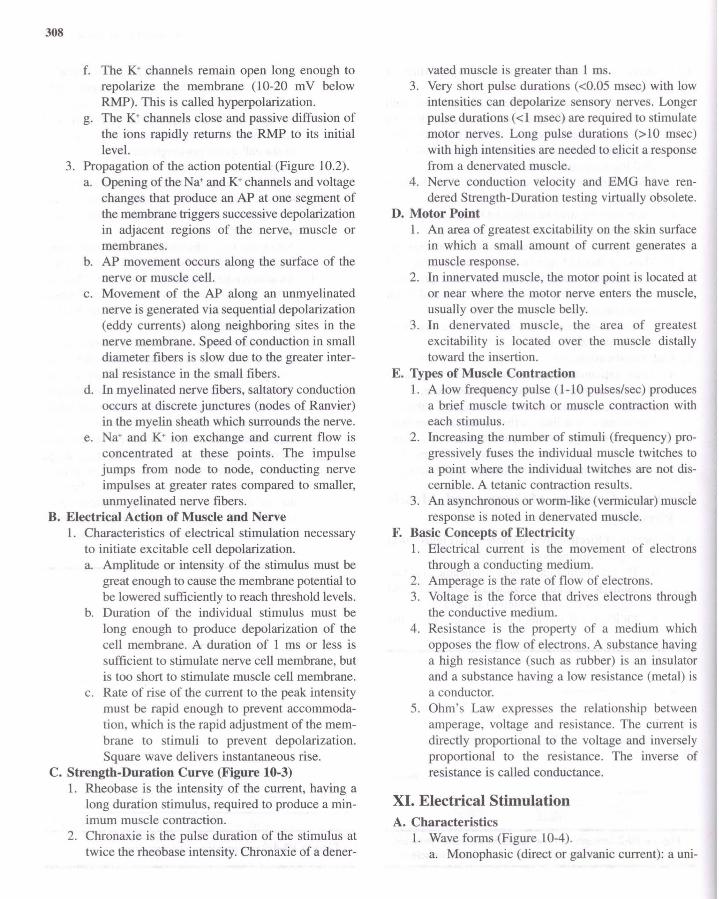
f. The K+ channels remain open long enough to repolarize the membrane (10-20 mV below RMP). This is called hyperpolarization.
g. The K+ channels close and passive diffusion of the ions rapidly returns the RMP to its initial level.
3. Propagation of the action potential (Figure 10.2). a. Opening of the Na+ and K+ channels and voltage
changes that produce an AP at one segment of the membrane triggers successive depolarization in adjacent regions of the nerve, muscle or membranes.
b. AP movement occurs along the surface of the nerve or muscle cell.
c. Movement of the AP along an unmyelinated nerve is generated via sequential depolarization (eddy currents) along neighboring sites in the nerve membrane. Speed of conduction in small diameter fibers is slow due to the greater internal resistance in the small fibers.
d. In myelinated nerve fibers, saltatory conduction occurs at discrete junctures (nodes of Ranvier) in the myelin sheath which surrounds the nerve.
e. Na+ and K+ ion exchange and current flow is concentrated at these points. The impulse jumps from node to node, conducting nerve impulses at greater rates compared to smaller, unmyelinated nerve fibers.
B. Electrical Action of Muscle and Nerve 1. Characteristics of electrical stimulation necessary
to initiate excitable cell depolarization. a. Amplitude or intensity of the stimulus must be
great enough to cause the membrane potential to be lowered sufficiently to reach threshold levels.
b. Duration of the individual stimulus must be long enough to produce depolarization of the cell membrane. A duration of 1 ms or less is sufficient to stimulate nerve cell membrane, but is too short to stimulate muscle cell membrane.
c. Rate of rise of the current to the peak intensity must be rapid enough to prevent accommodation, which is the rapid adjustment of the membrane to stimuli to prevent depolarization. Square wave delivers instantaneous rise.
C. Strength-Duration Curve (Figure 10-3) 1. Rheobase is the intensity of the current, having a
long duration stimulus, required to produce a minimum muscle contraction.
2. Chronaxie is the pulse duration of the stimulus at twice the rheobase intensity. Chronaxie of a dener-
vated muscle is greater than 1 ms. 3. Very short pulse durations « 0.05 msec) with low
intensities can depolarize sensory nerves. Longer pulse durations (<1 msec) are required to stimulate motor nerves. Long pulse durations (>10 msec) with high intensities are needed to elicit a response from a denervated muscle.
4. Nerve conduction velocity and EMG have rendered Strength-Duration testing virtually obsolete.
D. Motor Point 1. An area of greatest excitability on the skin surface
in which a small amount of current generates a muscle response.
2. In innervated muscle, the motor point is located at or near where the motor nerve enters the muscle, usually over the muscle belly.
3. In denervated muscle, the area of greatest excitability is located over the muscle distally toward the insertion.
E. Types of Muscle Contraction 1. A low frequency pulse (1-10 pulses/sec) produces
a brief muscle twitch or muscle contraction with each stimulus.
2. Increasing the number of stimuli (frequency) progressively fuses the individual muscle twitches to a point where the individual twitches are not discernible. A tetanic contraction results.
3. An asynchronous or worm-like (vermicular) muscle response is noted in denervated muscle.
F. Basic Concepts of Electricity I . Electrical current is the movement of electrons
through a conducting medium. 2. Amperage is the rate of flow of electrons. 3. Voltage is the force that drives electrons through
the conductive medium. 4. Resistance is the property of a medium which
opposes the flow of electrons. A substance having a high resistance (such as rubber) is an insulator and a substance having a low resistance (metal) is a conductor.
5. Ohm's Law expresses the relationship between amperage, voltage and resistance. The current is directly proportional to the voltage and inversely proportional to the resistance. The inverse of resistance is called conductance.
XI. Electrical Stimulation A. Characteristics
1. Wave forms (Figure 10-4). a. Monophasic (direct or galvanic current): a uni-

directional flow of charged particles. A current flow in one direction for a finite period of time is a phase (upward or downward deflection from and return to baseline). It has either a positive or negative charge.
b. Biphasic wave (alternating current): a bidirectional flow of charged particles. This type of wave form is illustrated as one-half of the cycle above the baseline and the second phase below the baseline. One complete cycle (two phases) equals a single pulse. It has a zero net charge if symmetrical.
c. Polyphasic wave: biphasic current modified to produce three or more phases in a single pulse. This waveform in medium frequency may be Russian or Interferential current.
B. Current Modulation a. Continuous mode: uninterrupted flow of current. b. Interrupted mode: intermittent cessation of cur
rent flow for one second or more. c. Surge mode: a gradual increase and decrease in
the current intensity over a finite period of time.
d. Ramped mode: a time period with a gradual rise of the current intensity which is maintained at a selected level for a given period of time followed by a gradual or abrupt decline in intensity.
e. Goals and Indications 1. Pain modulation.
a. Activation of gate mechanisms (Gate Theory). b. Initiation of descending inhibition mechanisms
(endogenous opiate production). 2. Decrease muscle spasm.
a. Muscle fatigue: tetanic contraction sustained for several minutes via continuous modulation.
b. Muscle pump: interrupted or surge modulation producing rhythmic contraction and relaxation of the muscle to increase circulation.
c. Muscle pump and heat: combination of electrical stimulation and ultrasound to increase tissue temperature and produce muscle pumping at the same time.
3. Impaired range of motion (increase in or maintenance of joint mobility). a. Mechanical stretching of connective tissue and
muscles associated with a joint. Used when muscle strength is deficient or neuromuscular dysfunction (e.g., spasticity) prevents adequate joint movement.
Therapeutic Modalities 309
b. Decrease pain to encourage joint motion. c. Decrease in edema if significant impediment to
motion. 4. Muscle re-education (training muscles to respond
appropriately to volitional effort). a. Act as active assistive exercise. b. Provide proprioceptive feedback. c. Assist in coordinated muscle movement.
5. Disuse atrophy (muscle weakness). a. Used as an adjunct to volitional movement.
6. Soft tissue repair (wound healing). a. Pulsed currents (monophasic, biphasic, polypha
sic) with interrupted modulations. Improved circulation via the muscle pump to improve tissue nutrition and hasten metabolic waste disposal.
b. Monophasic currents (low volt continuous modulations, high volt pulsed currents). (1) Electrical potential theory. Restoration of
electrical charges in wound area. (2) Bactericidal effect. Disruption of DNA,
RNA synthesis or cell transport system of microorganisms.
(3) Biochemical effects. Increased ATP concentration, amino acid uptake, increased protein and DNA synthesis.
(4) Galvanotaxic effect. Attraction of tissue repair cells via electrode polarity. (a) Inflammation phase: macrophages
(positive); mast cells (negative); neutrophils (positive or negative).
(b) Proliferation phase: fibroblasts (positive).
(c) Wound contraction phase: alternating positive/negative.
(d) Epithelialization phase: epithelial cells (positive).
c. Both low intensity continuous non-pulsed low volt direct current and high volt pulsed current can be applied for wound healing. Though the current characteristics (continuous vs. pulse) differ, the treatment protocols are similar (low amplitude current for 30-60 minutes) .
7. Edema reduction. a. Muscle pump. Increase lymph and venous flow. b. Electrical field phenomenon. Effect of electrical
charge on interstitial proteins increase lymph and venous flow.
8. Spasticity (ES to reduce hypertonicity). a. Fatigue of the agonist.

310
b. Reciprocal inhibition (stimulate antagonist! inhibit agonist).
9. Denervated muscle. a. Controversy exists relative to the use of electrical
stimulation for denervated muscle. Previous animal and clinical studies indicated that denervated muscle can be stimulated by monophasic or biphasic currents with a long pulse duration, producing a vermicular contraction. The goal of stimulation was to retard the effects of disuse atrophy and shorten recovery time.
b. Recent animal studies suggest that electrical stimulation may be deleterious to denervated muscle by: (1) Interfering with regeneration of neuromus
cular junction and subsequent reinnervation. (2) Traumatizing hypersensitive denervated
muscle. c. The financial cost and prolonged treatment
time required until reinnervation occurs are additional factors to consider when contemplating using electrical stimulation on denervated muscles.
C. Contraindications 1. Electrical stimulation should not be placed over:
a. Healing fractures. b. Areas of active bleeding. c. Malignancies or phlebitis in treatment area. d. Superficial metal implants. e. Pharyngeal or laryngeal muscles. f. Electrical stimulation should not be applied to
patients with demand-type pacemaker, myocardial disease.
2. Use precaution in applying electrical stimulation to areas of impaired sensation and severe edema.
3. Do not use any electrical modality if there is evidence of broken or frayed wires or if the unit is not connected to a ground fault circuit interrupter (see hydrotherapy section).
D. General Guidelines for Electrical Stimulation Procedures I. General muscle stimulation procedure.
a. Explain procedure and effects to patient. b. Place patient in comfortable position with
treatment area properly exposed. c. Support body part to be treated. d. Assess skin condition and sensation. e. Reduce skin resistance, if necessary (hot pack,
alcohol rub, gentle abrasion). f. Check to see that all controls are in proper
starting position before turning on the modality. g. Electrode selection.
(1) Electrode size. (a) Two electrodes (leads) are required to
complete the current circuit. One electrode is generally called the active (stimulating) electrode and is often placed on the motor point; the second, larger electrode, is called the dispersive electrode.
(b) Current density (the amount of current that is dispersed under the electrode) is relative to the electrode size. A given current intensity passing through the smaller active electrode produces high current density and thus a strong stimulus while the same current is perceived as less intense under the larger dispersive electrode because of the lesser current density.
(c) Electrode size should be relative to the size of the treatment site. Large electrodes in a small treatment area (i.e., forearm) could result in current overflowing to surrounding muscles producing undesired effects.
(d) Conversely, small electrodes applied to a large muscle (i.e. , quadriceps) could result in high current density under the electrodes making electrical stimulation uncomfortable to the patient.
h. The active electrode is usually placed over the treatment site (motor point), so as to produce a stimulation effect. The dispersive electrode may be placed on the treatment site or at a remote site (see electrode placement).
i. Electrode preparation. (1) Metal plate/sponge: remove sponge from
water, remove excess water. (2) Carbonized rubber: place small amount of
gel in center of electrode. Spread gel to cover entire surface.
(3) Pregelled electrode: remove protective cover and place a small amount of gel (metal mesh/foil electrode) or water (Karaya electrode) on electrode.
j. Electrode placement. (1) Unipolar/monopolar placement: one single
electrode or multiple (bifurcated) active electrodes placed over treatment area.

Usually larger-sized dispersive electrode (inactive) placed ipsilaterally away from treatment area.
(2) Bipolar placement: equal sized active and dispersive electrodes on same muscle group or in same treatment area. Smaller bifurcated treatment electrodes may be used to better conform to small treatment areas.
(3) The space between the active and dispersive electrodes should be at least the diameter of the active electrode. The distance between the electrodes should be as far as is practicable. The greater the space between electrodes the lesser the current density in the intervening superficial tissue, thus minimizing the risk of skin irritation, and burns. If deep penetration causes contraction of undesired muscles, move the electrodes closer together.
k. Inspect the patient's skin. Vigilant skin inspection and skin care is very important with long-term use of electrical stimulation. This is especially important during home use of transcutaneous electrical stimulation and other electrical stimulation modalities. Long-term repetitive stimulation and electrode placement and removal can irritate the skin and initiate skin breakdown.
I. Secure electrodes to body part. m. Set appropriate frequency, waveform and mod
ulation rate. n. Adjust intensity to achieve the optimal treatment
effect. o. At end of treatment, slowly decrease intensity
to zero before lifting the active electrode from skin. Turn all controls to beginning position.
2. Muscle strengthening, muscle spasm or edema
Therapeutic Modalities 311
(muscle pump), ROM. a. Slowly increase intensity until a muscular
response is observed. b. 10 to 25 muscle contractions may be sufficient
to obtain treatment goal. c. Duty cycle.
(1) Interrupted/ramped modulation of current allows the muscle to recover between stimulation periods.
(2) It has been shown that stimulation on to off ratios of 1:3 or more minimize the fatigue effects of electrical stimulation.
3. Muscle spasm (fatigue). a. Procedure as above for innervated muscle.
Current applied in continuous mode. 4. Muscle re-education.
a. Parameters and procedure similar to muscle strengthening techniques.
b. Stimulation for multiple sets of singular or multiple muscle repetitions.
c. Treatment sessions of 10-30 minutes depending on patient's mental and physical tolerance.
XII. Iontophoresis A. Description
1. The application of a continuous direct current to transport medicinal agents through the skin or mucous membrane for therapeutic purposes.
B. Physics 1. Like charges repel like charges. 2. Unlike charges attract unlike charges.
C. Electrochemical Effects Related to Iontophoresis 1. Dissolved acids, bases, salts, or alkaloids in an
aqueous solution dissociate into positively or negatively charged substances (ions) when electrical
TABLE 10-7 -INDICATIONS FORTHE USE OF IONTOPHORESIS AND IONS COMMONLY USED
INDICATIONS ION POLARITY SOURCE
Analgesia Lidocaine, Xylocaine Positive Lidocaine, Xylocaine
Salicylate Negative Sodium salicylate
Calcium deposits Acetate Negative Acetic acid
Dermal ulcers Zinc Positive Zinc oxide
Edema reduction Hyaluronidase Positive Wyadase
Fungal infections Copper Positive Copper sulfate
Hyperhidrosis Water Positive/Negative Tap Water
Muscle spasm Calcium Positive Calcium chloride
Magnesium Positive Magnesium sulfate
Musculoskeletal Dexamethasone Negative
inflammatory conditions Hydrocortisone Positive

312
current flows through a substance. 2. Polar effects.
a. Positive ions move toward the negative pole (cathode) where a secondary alkaline reaction (NaOH) occurs.
b. Negative ions move toward the positive pole (anode) where an acid is produced (HCI).
D. Ion Transfer 1. The number of ions transferred through the skin is
directly related to the: a. Duration of the treatment. b. Current density. c. Concentration of the ions in the solution.
E. Electrical Stimulation Characteristics oflontophoresis 1. Wave form: monophasic. 2. Modulation: continuous.
F. Procedure 1. Clean and inspect skin. 2. Position patient and support treatment area. 3. Place appropriate size active electrode on treat
ment area. Active electrode same polarity as the medicinal ion. To reduce the alkaline effect on the skin, the negative electrode should be twice as large as the positive regardless of which is the active electrode.
4. Dispersive electrode placed at either proximal or distal distant site about 4-6 inches away.
5. The space between the active and dispersive electrodes should be at least the diameter of the active electrode. However, commercial electrode sets have a fixed distance that limits the spacing between electrodes.
6. Determine dose. Dosage is product of time and current intensity. Safe limit for active electrode: anode, 1.0 mA/cm2, cathode, 0.5 mA/cm2
•
Duration is 10-40 minutes. 7. Turn intensity up slowly to selected level unless
9 A·Bell
0 .I 0e1 TwcbReceptor
@
0 6 Inhibitory Interneurtm ~
C5 • X
A-Oelta,C·Fibcr Pree Nerve Endina
Figure 10-5: Schematic of gate control theory (Melzack and Wall).
apparatus automatically adjusts parameters. 8. Observe treatment area every 3-5 minutes. Report
any adverse reactions. 9. Turn intensity down slowly to zero at completion
of treatment. Some units have an automatic cut-off. G. Indications (Table 10-7) H. Contraindications
1. Refer to general rules for electrical stimulation. 2. Impaired skin sensation. 3. Allergy or sensitivity to therapeutic agent or direct
current. 4. Denuded area or recent scars. 5. Cuts, bruises or broken skin. 6. Metal in or near treatment area.
XIII. Transcutaneous Electrical Nerve Stimulation (TENS)
A. Description 1. Transcutaneous electrical nerve stimulation is
designed to provide afferent stimulation for pain management.
B. Physiological Effects 1. Pain modulation through activation of central inhi
bition of pain transmission (Gate Control Theory). a. Large diameter A-Beta fibers (Figure 10-5) acti
vate inhibitory interneurons (substantia gelatinosa) located in the dorsal horn (primarily lamina II and ill) of the spinal cord, producing
Dorsolateral Tract
+
Periaqueductal GnlY Mauer
o Enkephalin Interneuron
,--~'" ~ O +
( A-Delta. C-Fibc.r
+
Ascending Tract
Figure 10:6: Schematic of descending inhibition mechanisms.

inhibition of smaller A-Delta and C-Fibers (pain fibers).
b. Presynaptic inhibition of the T-cells closes the "gate" and modulates pain. The gating mechanism also includes release of enkephalins which combine with opiate receptors to depress release of substance P from the A-delta and C-fibers.
2. Pain modulation through descending pathways generating endogenous opiates (Figure 10-6). a. Noxious stimuli generate endorphin production
from the pituitary gland and other CNS areas. b. Endogenous opiate-rich nuclei, periaqueductal
gray matter (pAG), in the midbrain and thalamus are also activated by strong stimuli.
c. Neurotransmitters from the PAG facilitate the cells of the nucleus raphe magnus (NRM), and reticularis gigantocellularis (RGC).
d. Efferents from these nuclei travel through the dorsal lateral funiculus to terminate on the enkephalinergic intemeurons in the spinal cord to presynaptically inhibit the release of substance P from the A-Delta and C-Fibers.
C. Electrical Stimulation Characteristics 1. Wave form: typically, asymmetrical biphasic with
a zero net direct current component. Other variations including pulsed monophasic current have been used.
2. Modulation: continuous or burst. D. Procedures ,
1. Conventional (high rate) TENS: this most common mode of TENS can be applied during the acute or chronic phase of pain. Modulation of pain via inhibition of pain fibers by large-diameter fiber activation (gate mechanism). Onset of pain relief is relatively fast and duration of relief is relatively short.
'l"l'Qu~ .. cy(KIb;)
Figure I 0-7: Capacitive skin resistance decreases as current frequency increases.
Therapeutic Modalities 313
a. Amplitude: comfortable tingling sensation, paresthesia. No muscle response.
b. Pulse rate 50-80 pps. c. Pulse duration 50-1 00 ~sec. d. Duration of treatment: 20-60 min. e. Duration of pain relief: temporary.
2. Acupuncture-like (strong low rate) TENS can be applied during the chronic phase of pain. Analgesia produced through stimulation-evoked production of endogenous opiates. Onset of pain relief may be as long as 20 to 40 minutes. Duration of relief may be long-lasting (an hour or more). a. Amplitude: strong, but comfortable rhythmic
muscle twitches. b. Pulse rate: 1-5 pps. c. Pulse duration: 150-300 ~sec. d. Duration of treatment: 30-40 min. e. Duration of pain relief: long lasting.
3. Brief intense TENS: this mode is used to provide rapid onset, but short-term pain relief during painful procedures (wound debridement, deep friction massage, joint mobilization or passive stretching). a. Amplitude: to patient's tolerance. b. Pulse rate: 80-150 pps. c. Pulse duration: 50-250 ~sec .
d. Duration of treatment: 15 min. e. Duration of pain relief: temporary (30 minutes
hour). 4. Burst mode (pulse trains) TENS: combines char
acteristics of both high and low rate TENS. Stimulation of endogenous opiates, but current is
o 01\ 0 0 0 0 0 0 0 0 0 0 0 UlJUUUUUMUUvV
00000 UlJ U U V
Burst
IOms
Carrier frequency
2.soo pps
lnterbursl interval
IOms
00000 U U vU V
IOms
Figure 10-8: Russian current. Time-modulated polyphasic wavefo rm

314
more tolerable to patient than low rate TENS. Onset of analgesia similar to low rate TENS. a. Amplitude: comfortable, intermittent paresthesia. b. Pulse rate: 50-100 pps delivered in packets or
bursts of 1-4 pps. c. Pulse duration: 50-200 /lsec. d. Duration of treatment: 20-30 min. e. Duration of pain relief: long lasting (hours).
5. Hyperstimulation (point stimulation) TENS: use of a small probe to locate and noxiously stimulate acupuncture or trigger points. Multiple sites may be stimulated per treatment. Onset of pain relief is similar to acupuncture-like TENS. a. Amplitude: strong, to patient's tolerance. b. Pulse rate 1-5 pps. c. Pulse duration 150-300 /lsec. d. Duration of treatment: 15 to 30 second incre
ments. e. Duration of pain relief: long lasting.
6. Modulation mode TENS: a method of modulating
Circuit 1: 3,000 Hz
r /\ f\ A A f\ ........ f\ .. " A ' A " lY"f\/\
v v V v V v. ... V v. V . V .......... v ...... v... V .. Circuit 2: 3,100 Hz
f\ f\ "
v
Circujt t + Circuit 2 Superimposed
v
v
A
v
fI
v v
B
f\ ... (\ ...... "(\ .. f\ '" . T\
1.1 ...•. 1.1 •.
f\ f\
(\ u
v
v v V v
v C Beat Frequency (100Hz)
Figure 10-9: Interferential current. Amplitude modulated polyphasic waveform.
the parameters of the above TENS modes for the purpose of preventing neural or perceptual adaptation due to constant electrical stimulation. Frequencies, intensities or pulse durations can be altered by ten or more percent one or two times per second.
E. Electrode Placement 1. Several options should be considered.
Acupuncture site, dermatome distribution of involved nerve, over painful site, proximal or distal to pain site, segmentally related myotomes, or trigger points.
F. Goals and Indications 1. Acute and chronic pain modulation.
G. Contraindications 1. Patient with demand-type pacemaker or over chest
of patient with cardiac disease. 2. TENS not applied over eyes, laryngeal or pharyngeal
muscles, head and neck of patient following cerebral vascular accident, or with epilepsy.
3. TENS not applied to mucosal membranes.
XlV. High Voltage Stimulation
Pulsed Galvanic
A. Description: high voltage pulsed current (HYPC). Typically, monophasic twin-peaked pulses of short duration.
~ 1------1 ~
Figure 10-10: Static interference field depicting the area of maximum stimulation (circle) and the direction of maximal stimulation (arrows).
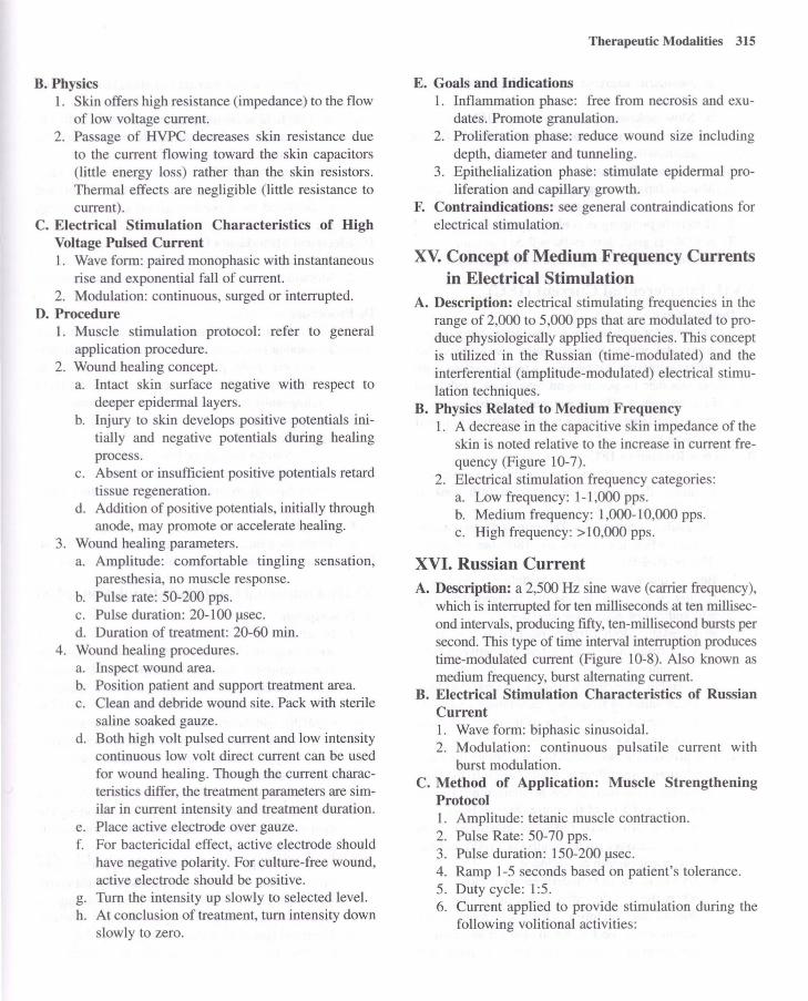
B. Physics 1. Skin offers high resistance (impedance) to the flow
of low voltage current. 2. Passage of HVPC decreases skin resistance due
to the current flowing toward the skin capacitors (little energy loss) rather than the skin resistors. Thermal effects are negligible (little resistance to current).
C. Electrical Stimulation Characteristics of High Voltage Pulsed Current 1. Wave form: paired monophasic with instantaneous
rise and exponential fall of current. 2. Modulation: continuous, surged or interrupted.
D. Procedure 1. Muscle stimulation protocol: refer to general
application procedure. 2. Wound healing concept.
a. Intact skin surface negative with respect to deeper epidermal layers.
b. Injury to skin develops positive potentials initially and negative potentials during healing process.
c. Absent or insufficient positive potentials retard tissue regeneration.
d. Addition of positive potentials, initially through anode, may promote or accelerate healing.
3. Wound healing parameters. a. Amplitude: comfortable tingling sensation,
paresthesia, no muscle response. b. Pulse rate: 50-200 pps. c. Pulse duration: 20-100 flsec. d. Duration of treatment: 20-60 min.
4. Wound healing procedures. a. Inspect wound area. b. Position patient and support treatment area. c. Clean and debride wound site. Pack with sterile
saline soaked gauze. d. Both high volt pulsed current and low intensity
continuous low volt direct current can be used for wound healing. Though the current characteristics differ, the treatment parameters are similar in current intensity and treatment duration.
e. Place active electrode over gauze. f. For bactericidal effect, active electrode should
have negative polarity. For culture-free wound, active electrode should be positive.
g. Turn the intensity up slowly to selected level. h. At conclusion of treatment, turn intensity down
slowly to zero.
Therapeutic Modalities 315
E. Goals and Indications 1. Inflammation phase: free from necrosis and exu
dates. Promote granulation. 2. Proliferation phase: reduce wound size including
depth, diameter and tunneling. 3. Epithelialization phase: stimulate epidermal pro
liferation and capillary growth. F. Contraindications: see general contraindications for
electrical stimulation.
xv. Concept of Medium Frequency Currents in Electrical Stimulation
A. Description: electrical stimulating frequencies in the range of 2,000 to 5,000 pps that are modulated to produce physiologically applied frequencies. This concept is utilized in the Russian (time-modulated) and the interferential (amplitude-modulated) electrical stimulation techniques.
B. Physics Related to Medium Frequency 1. A decrease in the capacitive skin impedance of the
skin is noted relative to the increase in current frequency (Figure 10-7).
2. Electrical stimulation frequency categories: a. Low frequency: 1-1,000 pps. b. Medium frequency: 1,000-10,000 pps. c. High frequency: > 10,000 pps.
XVI. Russian Current A. Description: a 2,500 Hz sine wave (carrier frequency),
which is interrupted for ten milliseconds at ten millisecond intervals, producing fifty, ten-millisecond bursts per second. This type of time interval interruption produces time-modulated current (Figure 10-8). Also known as medium frequency, burst alternating current.
B. Electrical Stimulation Characteristics of Russian Current 1. Wave form: biphasic sinusoidal. 2. Modulation: continuous pulsatile current with
burst modulation. C. Method of Application: Muscle Strengthening
Protocol 1. AmplitUde: tetanic muscle contraction. 2. Pulse Rate: 50-70 pps. 3. Pulse duration: 150-200 flsec. 4. Ramp 1-5 seconds based on patient's tolerance. 5. Duty cycle: 1:5. 6. Current applied to provide stimulation during the
following volitional activities:

316
a. Isometric exercise at several points through ROM.
b. Slow isokinetic exercise; e.g., 5°-100 /sec. c. Short arc joint movement when ROM is
restricted. D. Muscle Spasm Protocol
1. Muscle fatigue using continuous isometric contraction for several minutes to tolerance.
2. If muscle pumping is goal, duty cycle is 1: 1. 3. If ROM is goal, duty cycle is 2:5.
E. Contraindications: see general contraindications.
XVII. Interferential Current (IFC) A. Description
1. This current is characterized by the crossing oftwo sinusoidal waves having similar amplitudes, but different carrier frequencies which interfere with one another to generate an amplitude modulated beat frequency. The consequent beat frequency is the net difference between the two superimposed frequencies.
B. Physics Related to IFC 1. Constructive interference: when the two waves are
in phase, the sum of the superimposed wave is large (Figure 10-9 A).
2. Destructive interference. The sum of the two waves is zero when the waves are 180° out of phase (Figure 10-9 B).
3. Beat frequency (amplitude modulated). Resultant frequency produced by the two frequencies going into and out of phase (Figure 10-9 C). a. Constant. Both carrier frequencies are fixed.
Beat frequency is net difference between both frequencies.
b. Variable. One carrier frequency is fixed and the other varies in frequency generating a variable or sweep frequency. Sweep used to minimize accommodation.
4. IFC produces a cloverleaf-like pattern as the electrical stimulating effect is at a 45° angle to the flow of current in the two circuits as interference occurs at the targeted area of the body (Figure 10-10). a. Static interferential fields are generated when
four electrodes (two circuits) are used and the cloverleaf pattern is produced.
b. Dynamic (scan) interferential fields occur when the interferential fields are rotated 45° due to the vectoring effect of rhythmically unbalancing the IFC to change the position of the stimulation areas. This effect is purported
to provide a greater area of stimulation as compared to static interferential fields.
c. Full field scanning produces a similar effect as dynamic interferential fields by bursting the current over the two circuits.
5. When applying IFC to a small area (two electrodes), the interference occurs in the ES unit and is delivered as a pre-modulated current through one circuit.
C. Electrical Stimulation Characteristics 1. Wave form: sinusoidal (amplitude-modulated). 2. Modulation: continuous (pain); interrupted (muscle
exercise). D. Procedure
1. Electrode placement (pad or suction cup electrodes). a. Bipolar (premodulated IFC). Active and disper
sive electrodes placed over or around small area. b. Quadripolar (IFC). Two sets of electrodes placed
diagonally to one another over large area. 2. Treatment parameters.
a. Pain protocol. (1) Similar to high or low rate TENS
b. Muscle strengthening protocol. (1) Similar to low or medium frequency elec
trical stimulation. E. Goals and Indications
1. Modulate pain: increase muscle strength or ROM. F. Contraindications: see general contraindications.
XVIII. Functional Electrical Stimulation (FES) A. Description
1. Functional electrical stimulation encompasses a wide range of stimulator units and techniques for disuse atrophy, impaired ROM, muscle spasm, muscle re-education and spasticity management. FES is also called neuromuscular stimulation (NMES) and functional neuromuscular stimulation. This section will describe FES as an alternative or supplement to the use of orthotic devices.
B. Shoulder Subluxation 1. Patients with CVA may initially exhibit weakness
or flaccid paralysis of the muscles supporting the glenohumeral joint, especially the supraspinatus and posterior deltoid.
2. The force of gravity acting on the unsupported upper extremity tends to stretch the ligamentous structures surrounding the glenohumeral joint resulting in severe pain and decreased upper extremity function.
3. Electrical stimulation characteristics of FES. a. Wave form: asymmetrical biphasic square.

b. Modulation: interrupted. 4. Procedure.
a. Electrode placement: bipolar. Electrodes on supraspinatus and posterior deltoid.
b. Treatment parameters. (1) Amplitude: tetanic muscle contraction to
patient's tolerance. (2) Pulse rate 12-25 pps. (3) Duration of treatment: 15-30 minutes.
Three times daily up to 6-7 hours. On/off ratio: 1:3 (2 sec: 6 sec) progressing to 12:1 (24 sec: 2 sec).
C. Dorsiflexion Assist in Gait Training 1. Patients with hemiplegia sometimes exhibit para
lyzed dorsiflexor and evertor muscles. 2. FES controls foot drop, and facilitates dorsiflexors
and evertors during swing phase. 3. Electrical stimulation characteristics.
a. Wave form: asymmetric biphasic square. b. Pulse duration: 20-250 flsec. c. Modulation: interrupted by foot switch.
4. Procedure. a. Electrode placement: bipolar. Peroneal (fibu
lar) nerve near head of fibula or anterior tibialis muscle.
b. Treatment parameters. (1) Amplitude: tetanic muscle contraction suf
ficient to decrease plantar flexion. (2) Pulse rate 30-300 pps. (3) Treatment mode: heel switch contains pres
sure-sensitive contact which stops stimulation during stance phase and activates stimulation during swing phase. Hand switch also allows therapist to control stimulation during gait.
D. Other Gait-Assisted Protocol Considerations 1. Placement of electrodes on appropriate muscles to
control muscles during push-off (plantar flexors, late swing phase (hamstrings), quadriceps and/or gluteals (stance phase).
2. Electrical stimulation characteristics: similar to dorsiflexion protocol.
3. Method of application: similar to dorsiflexion protocol except for electrode placement.
XIX. Electromyographic Biofeedback (EMG Biofeedback)
A. Description 1. Electronic instrument used to measure motor unit
action potentials (MUAP) that are generated by
Therapeutic Modalities 317
active muscles. The signals are detected, amplified and converted into audiovisual signals that are used to reinforce voluntary control.
B. Principles of EMG Biofeedback 1. Motor unit: the functional unit of the neuromuscular
system, consisting of the anterior hom cell, its axon, the neuromuscular junction, and all the muscle fibers innervated by the axon. Motor unit potentials (MUP) are measured in microvolts (IlV). The signals generated by the MUP, which contain both positive and negative phases, are also called a compound action potentials (CAP) since the sensors pick up signals from multiple motor units.
2. The signal is processed through amplification, rectification (positive and negative components of the signal are made unidirectional), and integration (area under curve is computed). The integrated signal provides readings in microvolt-seconds (IlV/s) and is displayed as the EMG biofeedback signal.
3. The EMG biofeedback signals, in conjunction with the patient's voluntary effort, are used to either increase or decrease muscle activity to achieve a functional goal.
C. Recording Electrodes 1. Surface electrodes.
a. Global detection: signals from more than one muscle.
b. Detection from mostly superficial muscles. c. Advantages: easy to apply, acceptable to
patient/client. d. Disadvantages: detection from mostly superfi
cial muscles and frequently from more than one muscle group.
2. Types of surface electrodes/sensors. a. Metal electrodes (silver-silver chloride): cupped
shaped to accommodate conducting gel. b. Disposable electrodes: pregelled center with
surrounding adhesive backing. c. Carbonized rubber electrodes (re-useable):
flexible to conform to body part. 3. Needle electrodes/sensors.
a. Local detection: signals from specific muscle or muscle group.
b. Detection of deep muscles. c. Used for EMG diagnosis or research. Rarely
used for EMG biofeedback. d. Advantages: detection of specific muscles. e. Disadvantages: requires skill to apply, less
acceptable to patient/client.
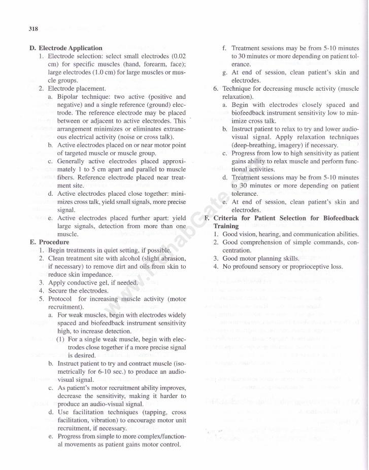
318
D. Electrode Application 1. Electrode selection: select small electrodes (0.02
cm) for specific muscles (hand, forearm, face); large electrodes (1.0 cm) for large muscles or muscle groups.
2. Electrode placement. a. Bipolar technique: two active (positive and
negative) and a single reference (ground) electrode. The reference electrode may be placed between or adjacent to active electrodes. This arrangement minimizes or eliminates extraneous electrical activity (noise or cross talk).
b. Active electrodes placed on or near motor point of targeted muscle or muscle group.
c. Generally active electrodes placed approximately 1 to 5 cm apart and parallel to muscle fibers. Reference electrode placed near treatment site.
d. Active electrodes placed close together: minimizes cross talk, yield small signals, more precise signal.
e. Active electrodes placed further apart: yield large signals, detection from more than one muscle.
E. Procedure 1. Begin treatments in quiet setting, if possible. 2. Clean treatment site with alcohol (slight abrasion,
if necessary) to remove dirt and oils from skin to reduce skin impedance.
3. Apply conductive gel, if needed. 4. Secure the electrodes. 5. Protocol for increasing muscle activity (motor
recruitment). a. For weak muscles, begin with electrodes widely
spaced and biofeedback instrument sensitivity high, to increase detection. (1) For a single weak muscle, begin with elec
trodes close together if a more precise signal is desired.
b. Instruct patient to try and contract muscle (isometrically for 6-10 sec.) to produce an audiovisual signal.
c. As patient's motor recruitment ability improves, decrease the sensitivity, making it harder to produce an audio-visual signal.
d. Use facilitation techniques (tapping, cross facilitation, vibration) to encourage motor unit recruitment, if necessary.
e. Progress from simple to more complex/functional movements as patient gains motor control.
f. Treatment sessions may be from 5-10 minutes to 30 minutes or more depending on patient tolerance.
g. At end of session, clean patient's skin and electrodes.
6. Technique for decreasing muscle activity (muscle relaxation). a. Begin with electrodes closely spaced and
biofeedback instrument sensitivity low to minimize cross talk.
b. Instruct patient to relax to try and lower audiovisual signal. Apply relaxation techniques (deep-breathing, imagery) if necessary.
c. Progress from low to high sensitivity as patient gains ability to relax muscle and perform functional activities.
d. Treatment sessions may be from 5-10 minutes to 30 minutes or more depending on patient tolerance.
e. At end of session, clean patient's skin and electrodes.
F. Criteria for Patient Selection for Biofeedback Training 1. Good vision, hearing, and communication abilities. 2. Good comprehension of simple commands, con
centration. 3. Good motor planning skills. 4. No profound sensory or proprioceptive loss.