Theory of machine ii 012110050121-1
15
Mechanical Engineering Department Lab Manual IV- Semester Subject: Theory of Machine – II List of Experiment: 1. Study of Gyroscopic effect and determination of gyroscopic couple. 2. Determination of jump sped of cam-follower system. 3. Dynamic balancing of the rotating mass system. 4. To determine radius of Gyration “K” of given pendulum. 5. To study the free vibration and to determine the natural frequency of vibration of Tow-Rotor system. 6. To study the torsional vibration and to determine the natural frequency vibration of single rotor system. 7. Study of longitudinal vibration and to determine the frequency of vibration. 8. To study the damped torsional vibration and determine the damping coefficient. 9. To verify the relation T = 2 Π √1/g for a simple pendulum. 10. Determination of whirling speed of shafts.
-
date post
13-Sep-2014 -
Category
Documents
-
view
1.233 -
download
3
description
Transcript of Theory of machine ii 012110050121-1
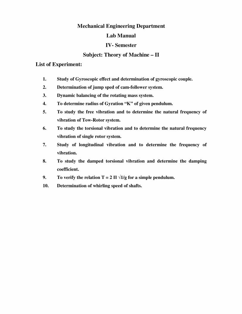
Mechanical Engineering Department
Lab Manual
IV- Semester
Subject: Theory of Machine – II
List of Experiment:
1. Study of Gyroscopic effect and determination of gyroscopic couple.
2. Determination of jump sped of cam-follower system.
3. Dynamic balancing of the rotating mass system.
4. To determine radius of Gyration “K” of given pendulum.
5. To study the free vibration and to determine the natural frequency of
vibration of Tow-Rotor system.
6. To study the torsional vibration and to determine the natural frequency
vibration of single rotor system.
7. Study of longitudinal vibration and to determine the frequency of
vibration.
8. To study the damped torsional vibration and determine the damping
coefficient.
9. To verify the relation T = 2 Π √1/g for a simple pendulum.
10. Determination of whirling speed of shafts.
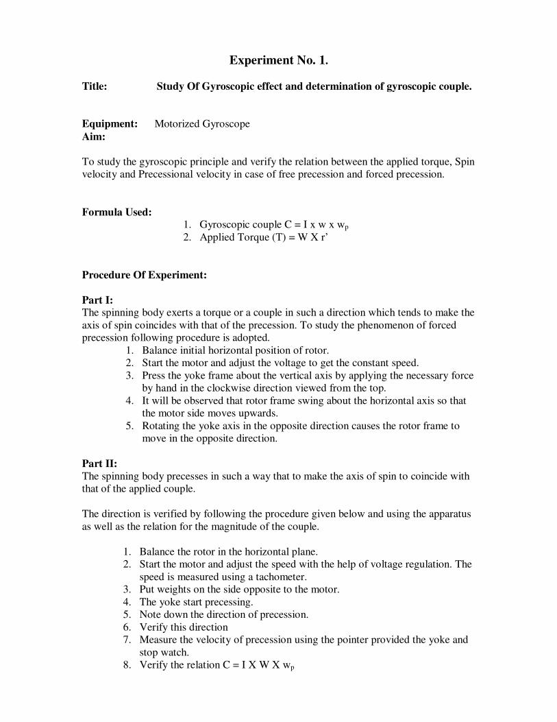
Experiment No. 1.
Title: Study Of Gyroscopic effect and determination of gyroscopic couple.
Equipment: Motorized Gyroscope
Aim:
To study the gyroscopic principle and verify the relation between the applied torque, Spin
velocity and Precessional velocity in case of free precession and forced precession.
Formula Used: 1. Gyroscopic couple C = I x w x wp
2. Applied Torque (T) = W X r’
Procedure Of Experiment:
Part I: The spinning body exerts a torque or a couple in such a direction which tends to make the
axis of spin coincides with that of the precession. To study the phenomenon of forced
precession following procedure is adopted.
1. Balance initial horizontal position of rotor.
2. Start the motor and adjust the voltage to get the constant speed.
3. Press the yoke frame about the vertical axis by applying the necessary force
by hand in the clockwise direction viewed from the top.
4. It will be observed that rotor frame swing about the horizontal axis so that
the motor side moves upwards.
5. Rotating the yoke axis in the opposite direction causes the rotor frame to
move in the opposite direction.
Part II:
The spinning body precesses in such a way that to make the axis of spin to coincide with
that of the applied couple.
The direction is verified by following the procedure given below and using the apparatus
as well as the relation for the magnitude of the couple.
1. Balance the rotor in the horizontal plane.
2. Start the motor and adjust the speed with the help of voltage regulation. The
speed is measured using a tachometer.
3. Put weights on the side opposite to the motor.
4. The yoke start precessing.
5. Note down the direction of precession.
6. Verify this direction
7. Measure the velocity of precession using the pointer provided the yoke and
stop watch.
8. Verify the relation C = I X W X wp

Observations:
Part I :
1. Direction of spin axis : CLOCKWISE/ANTICLOCKWISE
2. Direction of forced precession : DOWNWORD
3. Direction of couple acting on the frame : CLOCKWISE/ANTICLOCKWISES
Part II: 1. Mass of rotor (m) : 3kg
2. Thickness of rotor : 19mm
3. Rotor diameter (d) : 220mm
4. Moment arm (r’) : 200mm
5. Motor power : 120w
6. Speed of motor : 0 – 500 rpm
Observation Table:
Sr. No. Weight Kg.
(W)
Spin Speed
rpm (N)
Angle
turned
degrees (θ)
Time in
seconds (t)
Direction of
rotation
Calculations:
1. Moment of Inertia (I) = Kg.m²
2. w = 2πN / 60 = rad/s
3. wp = θ / t X π / 180 = rad/s
4. Gyroscopic Couple © = I X w X wp = N – m.
5. Applied Torque (T) = Wr’ = N – m.
Result Table :
Sr.
No.
Spin Velocity
w (rad / s)
Precessional velocity
wp
(rad / s )
Gyroscopic
Couple C (N.m)
Applied torque T
(N.m)
Conclusions :
a) Comments are to be written based on the observations of direction observed
during Part I and Part II of the experiment.
b) The values tabulated in the result table are to be compared (i.e. the values of C &
T are compared) and comments on the variation are to be written.
c) Different case where the gyroscopic couple is observed is to be mentioned.
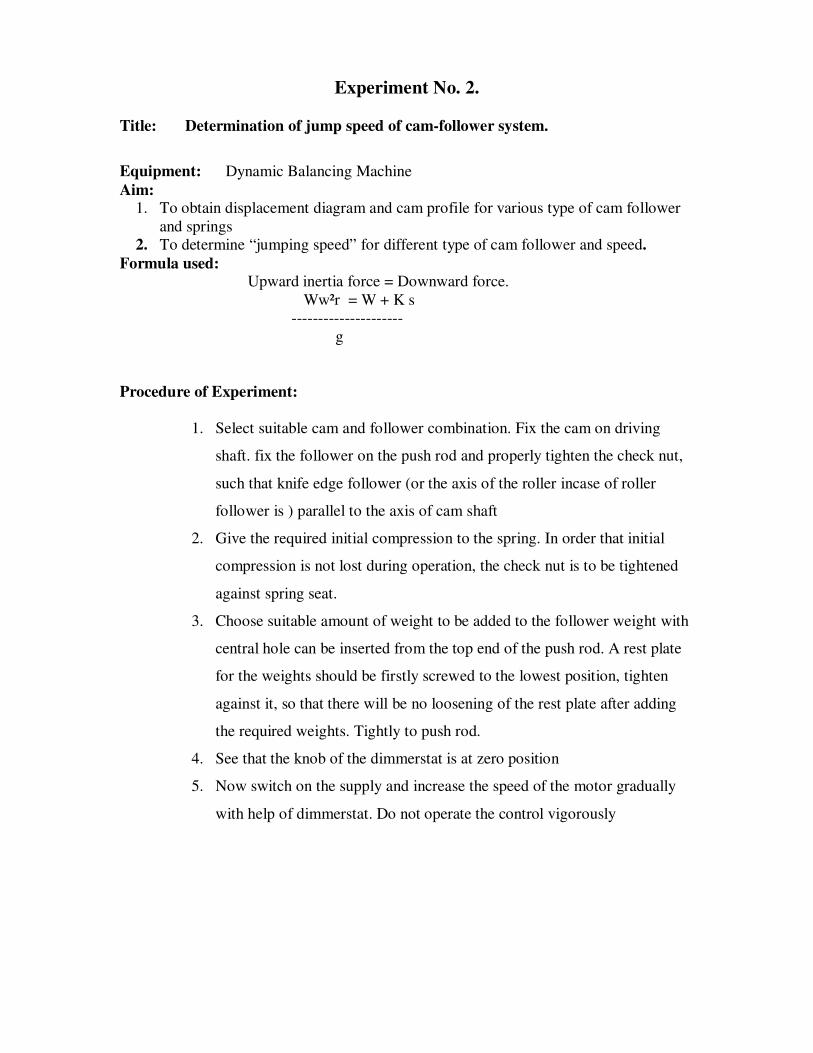
Experiment No. 2.
Title: Determination of jump speed of cam-follower system.
Equipment: Dynamic Balancing Machine
Aim: 1. To obtain displacement diagram and cam profile for various type of cam follower
and springs
2. To determine “jumping speed” for different type of cam follower and speed.
Formula used: Upward inertia force = Downward force.
Ww²r = W + K s
---------------------
g
Procedure of Experiment:
1. Select suitable cam and follower combination. Fix the cam on driving
shaft. fix the follower on the push rod and properly tighten the check nut,
such that knife edge follower (or the axis of the roller incase of roller
follower is ) parallel to the axis of cam shaft
2. Give the required initial compression to the spring. In order that initial
compression is not lost during operation, the check nut is to be tightened
against spring seat.
3. Choose suitable amount of weight to be added to the follower weight with
central hole can be inserted from the top end of the push rod. A rest plate
for the weights should be firstly screwed to the lowest position, tighten
against it, so that there will be no loosening of the rest plate after adding
the required weights. Tightly to push rod.
4. See that the knob of the dimmerstat is at zero position
5. Now switch on the supply and increase the speed of the motor gradually
with help of dimmerstat. Do not operate the control vigorously

Observations Table :
1. For Displacement diagram:
(a) For CAM I
Sr.
No.
θ Follower Type
1 2 3
Spring
A
B C D A B C D A B C D
1 20°
2 40°
3 Up
to
360°
(Note: Prepare separate table for CAM II)
2 For Jumping speed of follower for various spring force:
Follower Type
1 2 3 4 4
Sr.
No.
Spring
No.
Cam I II I II I II I II
1 A
2 B
3 C
4 D
3. For Jumping speed of follower at various weight:
Follower Type
1 2 3 4 4
Sr.
No.
Weight
(gms.)
Cam
I
II I II I II I II
1 A
2 B
3 C
4 D Result:
The jumping speed of follower is given in observation table
Calculations:
1. Cam profiles for the various types cam and follower are drawn and found to be
proportionate with actual profile of the cam.
2. The jumping speed varies with stiffness of the spring and downward weight.
Given:
Spring No. 1 (Yellow) = 93 gms.
Spring No.2 (White) = 82 gms.
Spring No. 3. (Red) = 47 gms.
Mushroom follower = 133gms.
Flat face follower =163gms.
Knife edge follower =100 gms.
Roller follower = 140gms.
Larger cam =164gms.
Small cam = 145gms.
Weight of follower Rod = 511gms.

Experiment No. 3
Title: Dynamic Balancing of Rotary Mass System
Equipment: Dynamic Balancing Machine
Aim:
1. To obtain balancing mass for static balancing of rotary mass system.
2. To obtain balancing mass for the rotating mass system
Formula Used:
Force = m x w² x r
Procedure Of Experiment:
1. Attached the balance frame to maintain frame firmly. Insert the card with pan
to the grooved pulley provided set the unit to 0 positions.
2. Values of static balancing for all the weights will be arrived when we are
conducting the experiment of dynamic balancing.
3. Now keep the block in any suitable position as reference and fix the second
block in any convenient position say 3cm to left.
4. Now hang the frame by chain and couple it with motor and run the motor by
using electric dimmer to a rated speed. By this way we can balance the
machine.
5. If the calculation is not correct then the unit will vibrate. That indicates there is
some calculation mistake at the time of drawing the force and couple polygon.
6. Attach any clock to the shaft at any position.
7. Put steel balls in one of the pans to bring the block to original 90° positions.
8. Number of balls proportional to the ‘wr’ value o block.
9. Repeat the experiment for other three blocks.
10. wr X No. of balls.
Observation Table:
Sr.
No.
Weight
(m) kg.
Radius
(r) m
Centrifugal
force
(w)rad/sec
Centrifugal
Force / W²
(m x r)
Distance
from RP
(I) m
Couple = m r l
1.
2.
3.
Calculations:
Force l = m x W² x r
Typical Result: (For Illustration o Experimental Calculations)
Experiments :
To statically balance a four place rotating mass system, Block No. 2 is to be
positioned 90 anticlockwise and 3cms. Along the shaft from block No. 1 determine the
angular and longitudinal positions of blocks 3 and 4 for perfect balance.
Conclusions:
1. The force and the couple polygon coming to be close hence the force produce
due to rotating masses are completely balance.
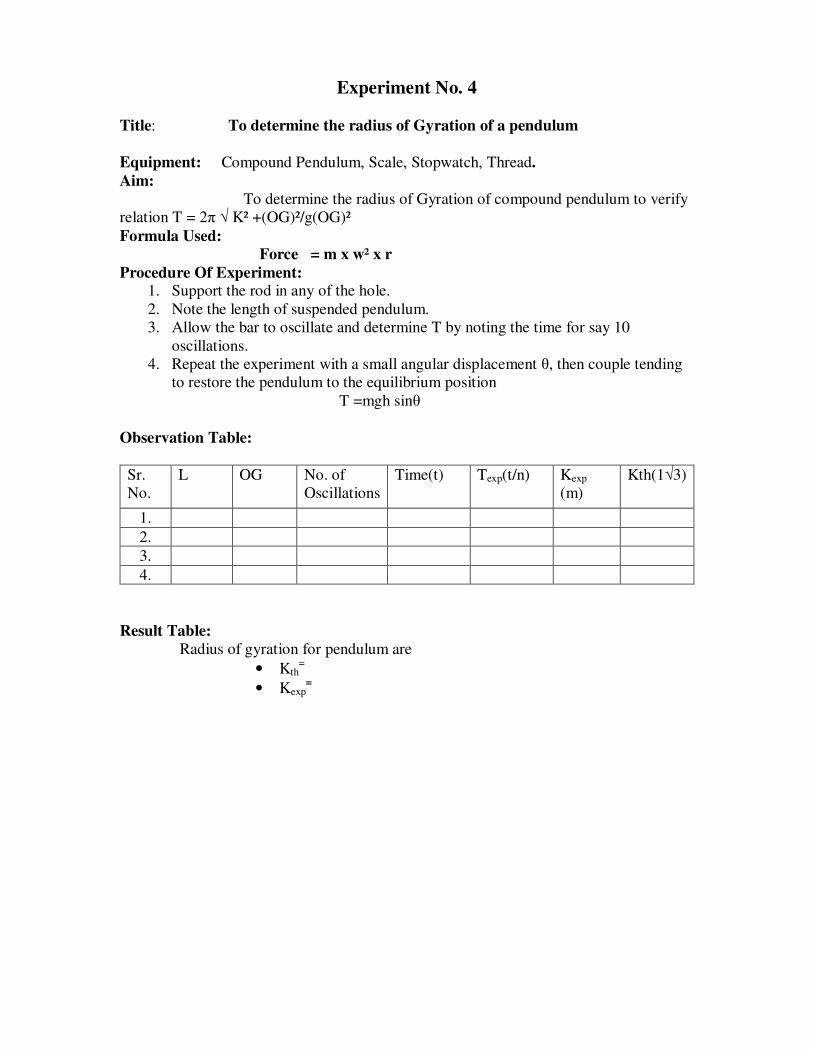
Experiment No. 4
Title: To determine the radius of Gyration of a pendulum
Equipment: Compound Pendulum, Scale, Stopwatch, Thread.
Aim:
To determine the radius of Gyration of compound pendulum to verify
relation T = 2π √ K² +(OG)²/g(OG)²
Formula Used:
Force = m x w² x r
Procedure Of Experiment: 1. Support the rod in any of the hole.
2. Note the length of suspended pendulum.
3. Allow the bar to oscillate and determine T by noting the time for say 10
oscillations.
4. Repeat the experiment with a small angular displacement θ, then couple tending
to restore the pendulum to the equilibrium position
T =mgh sinθ
Observation Table:
Sr.
No.
L OG No. of
Oscillations
Time(t) Texp(t/n) Kexp
(m)
Kth(1√3)
1.
2.
3.
4.
Result Table:
Radius of gyration for pendulum are
• Kth=
• Kexp=
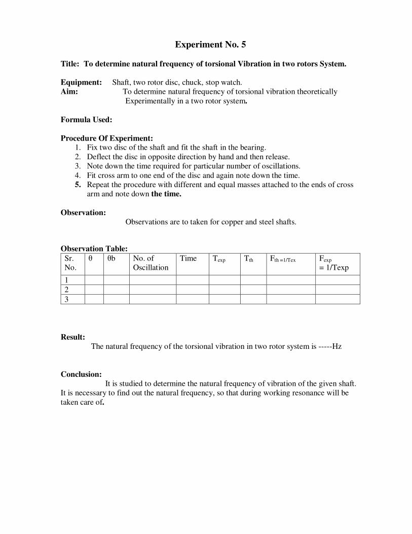
Experiment No. 5
Title: To determine natural frequency of torsional Vibration in two rotors System.
Equipment: Shaft, two rotor disc, chuck, stop watch.
Aim: To determine natural frequency of torsional vibration theoretically
Experimentally in a two rotor system.
Formula Used:
Procedure Of Experiment: 1. Fix two disc of the shaft and fit the shaft in the bearing.
2. Deflect the disc in opposite direction by hand and then release.
3. Note down the time required for particular number of oscillations.
4. Fit cross arm to one end of the disc and again note down the time.
5. Repeat the procedure with different and equal masses attached to the ends of cross
arm and note down the time.
Observation:
Observations are to taken for copper and steel shafts.
Observation Table:
Sr.
No.
θ θb No. of
Oscillation
Time Texp Tth Fth =1/Tex Fexp
= 1/Texp
1
2
3
Result:
The natural frequency of the torsional vibration in two rotor system is -----Hz
Conclusion:
It is studied to determine the natural frequency of vibration of the given shaft.
It is necessary to find out the natural frequency, so that during working resonance will be
taken care of.

Experiment No. 6
Title: To determine natural frequency of torsional Vibration in single rotor System.
Equipment: Vibration machine, Shaft, chuck, stop watch.
Formula Used:
Formula Used:
Tth =2π√ I/Kt
Procedure Of Experiment: 1. Fix the bracket at convenient position along the tower beam.
2. Grip one end of the shaft at bracket by the chuck.
3. Fix other end of shaft in the rotor.
4. Twist the motor rotor to some angle and then release.
5. Note down the time for no. of oscillations.
6. Repeat the procedure for different length of shaft.
Observation:
Observations are to taken for mild steel brass shafts.
Observation Table:
Sr.
No.
Len. Of
Shaft
No. of
oscillation
Time K Tth Texp Fth Fexp
1
2
3
Result: The natural frequency of the torsional vibration in single rotor system is---Hz
Conclusion: Natural frequency of torsional vibration experimental to theoretical is nearly
same.

Experiment No.7
Title: To study longitudinal vibration of a helical spring and to determine
the Frequency of vibration.
Equipment: Helical spring, rigid support, scale, stop-watch.
Formula Used: K = W/S
Texp = Time(t) / Oscillation(n)
Tth = 2π√ w/ Kmean
F = 1 / n
Procedure Of Experiment: 1. Fix one end of the helical spring to upper screw.
2. Determine the straight length of the helical spring at no load.
3. Put the known height of the platform at same distance.
4. For oscillations, Stretch the spring for some distance and leave it.
5. Count the time for no. of oscillations.
6. Determine the actual time period.
7. Repeat the same procedure for different weights.
Observation Table:
Sr.
No.
Wt.
Attached
Deflection
of spring
No. of
oscillation(n)
Time (t) Periodic time of
exp.
Tth
1
2
3
4
Result:
The mean actual frequency is found to be ------- and theoretical frequency is
Found to be -------
Conclusion:
It is found that the actual and the theoretical frequencies of the vibration close to
each other.
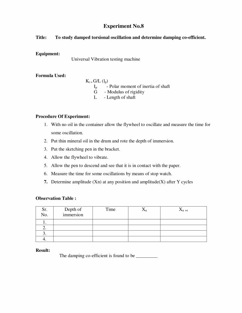
Experiment No.8
Title: To study damped torsional oscillation and determine damping co-efficient.
Equipment:
Universal Vibration testing machine
Formula Used:
Kt = G/L (lp)
Ip - Polar moment of inertia of shaft
G - Modulus of rigidity
L - Length of shaft
Procedure Of Experiment:
1. With no oil in the container allow the flywheel to oscillate and measure the time for
some oscillation.
2. Put thin mineral oil in the drum and rote the depth of immersion.
3. Put the sketching pen in the bracket.
4. Allow the flywheel to vibrate.
5. Allow the pen to descend and see that it is in contact with the paper.
6. Measure the time for some oscillations by means of stop watch.
7. Determine amplitude (Xn) at any position and amplitude(X) after Y cycles
Observation Table :
Sr.
No.
Depth of
immersion
Time Xn Xn +r
1.
2.
3.
4.
Result: The damping co-efficient is found to be _________

Experiment No.9
Title: To verify the relation T = 2 Π √1/g for a simple pendulum.
Equipment: Pendulum, Scale, Stopwatch, Thread.
Aim: To verify the relation T=2Π
Formula Used:
g1 2 T Π=
Procedure Of Experiment:
1. Attach the ball to one end of the thread.
2. Loosen the chuck and draw the thread to adjust the length.
3. Allow the pendulum to oscillate and determine time for number of oscillation (10).
4. Repeat the procedure by changing lengths of the pendulum.
5. Note the reading in the table.
Observation : For experimental frequency.
Observation Table:
Sr.
No.
Mass of Ball Length (cm) No. of
oscillati
ons(n)
Time (t sec) Texp (t/n) T th
1.
2.
3.
4.
Conclusion:
• The relation for time period T is verified.

Experiment No.10
Title: To study whirling phenomenon in shaft and observe various modes of
Vibration.
Equipment:
Whirling of shaft apparatus (rigid frame with motor, supporting ends.)
Formula Used:
Kt = m (r+e) (t)²
K – lateral stiffness of shaft
r – Distance
e – eccentricity
m – mass of disc
(t) – rotation speed
(t)n – natural frequency of lateral vibration
Procedure Of Experiment:
1. Choose the required size of the shaft.
2. Mount the two fixing ends on the frame to obtain the desired condition.
3. The shaft is fixed between two ends.
4. The motor is started.
5. Motor speed is increased slowly.
6. The amplitude of vibrations in lateral direction starts and mode shape is
observed.
7. The speed is noted down so also the mode shape and mode point.
8. To observe second mode shape the speed is increased further.
9. The speed and the mode shape is noted down.
10. The procedure is followed for different shafts and different end conditions.
Observation Table :
a) Diameter of shaft (d) = _____mm
b) Effective length of shaft (L) =_______mm
c)End conditions:
i) Motor end – simply supported / fixed
ii) Far end – simply supported / fixed
Sr. No. Mode Speed (rpm) Mode Shape
1
2
3
4

Result:
Sr. No. Mode Whirling Speed
1 Theoretical Observed
2
3