THEORETICAL AND EXPERIMENTAL ANALYSIS OF PISTON RING ...ijamtes.org/gallery/11.dec-11-138.pdf ·...
13
THEORETICAL AND EXPERIMENTAL ANALYSIS OF PISTON RING ASSEMBLY FRICTION OF A SINGLE CYLINDER VARIOUS CAPACITY I.C ENGINES Mr. Gaurav S.Verma Department of Thermal Engineering, lakshmi narain college of technology, indore Email:[email protected] Abstract: This paper presents the tribological scope is focus upon the major frictional components of the automobile engine e.g.: piston ring assembly (PRA). The current position surrounding the modeling of this Component will be reviewed and future possibilities identified. The frictional losses are in the PRA vary from 45% to 55% of total frictional losses. To reduce these frictional losses, various parametric approaches are made particularly at design stage and at experimental level. PRA friction is very complex phenomena under dynamic condition. Proper lubrication and selection of material pair also contributes to PRA friction. The theoretical model for PRA friction is being developed by considering different variables. These models are developed either theoretically or experimentally. The models are for specific PRA system with different capacity. Keywords: I.C Engine, piston ring assembly (PRA), frictional losses, friction force, lubricants, Tachometer. I. INTRODUCTION The internal combustion engine in particular the fuel that powers it consists of Main component like piston, crankshaft, cylinder block, connecting rod etc. Following fig shows the main engine components of an I.C engine. The popularity of the reciprocating internal combustion engine is due to its performance, reliability and versatility. The spark-ignited engines are widely used in public transportation. Piston of an internal combustion engine is the first component of the mechanism converting the chemical energy of the fuel into mechanical work. The heat produced in the combustion of the fuel, a large part of which is conducted to the cylinder liner surface by the piston ring pack, reduces the hardness and wear resistance of the piston and ring materials and causes oxidation and evaporation of the oil on the upper cylinder walls. The piston acts as a seal between the combustion and the crankcase, and is consequently to gas pressure with strong variations. The gas pressure gradient across the piston is utilized for increasing the contact pressure, and the second, compression ring against the cylinder liner surface, by allowing the cylinder pressure to act on the backside of the rings. An Engine is defined as a device, which converts energy from one form into another form. A heat engine is a device, which converts heat energy is a device, which converts heat energy into mechanical energy. The heat engine in which this conversion from heat energy to mechanical energy takes place inside the engine is known as an I.C engine. In conversion of energy from one form into another form, there is always some kind of losses of energy. These energy losses are due to the relative motion of various dynamic elements of an engine like crankshaft, connecting rod, rocker arm, push rod, valve mechanism, piston cylinder assembly etc. The power losses are generally in the pumping, exhaust, mechanical etc.The contribution of various dynamic systems is identified by number of scientists and estimated system wise in an I.C. Engine are asunder: Sr.No Type of system Contribution percentage 01 Cylinder-Piston Ring System 35% TO 45% 02 Crankshaft Bearing System 20% TO 30% 03 Engine Valve System 7% TO 10% 04 Engine Auxiliaries 20% TO 25% International Journal of Advanced in Management, Technology and Engineering Sciences Volume 7, Issue 12, 2017 ISSN NO : 2249-7455 http://ijamtes.org/ 90
Transcript of THEORETICAL AND EXPERIMENTAL ANALYSIS OF PISTON RING ...ijamtes.org/gallery/11.dec-11-138.pdf ·...

THEORETICAL AND EXPERIMENTAL ANALYSIS OF PISTON RING ASSEMBLY FRICTION OF A SINGLE CYLINDER
VARIOUS CAPACITY I.C ENGINES
Mr. Gaurav S.Verma
Department of Thermal Engineering, lakshmi narain college of technology, indore Email:[email protected]
Abstract:
This paper presents the tribological scope is focus upon the major frictional components of the automobile engine e.g.: piston ring
assembly (PRA). The current position surrounding the modeling of this Component will be reviewed and future possibilities identified. The frictional losses are in the PRA vary from 45% to 55% of total frictional losses. To reduce these frictional losses, various parametric approaches are made particularly at design stage and at experimental level. PRA friction is very complex phenomena under dynamic condition. Proper lubrication and selection of material pair also contributes to PRA friction. The theoretical model for PRA friction is being developed by considering different variables. These models are developed either theoretically or experimentally. The models are for specific PRA system with different capacity.
Keywords: I.C Engine, piston ring assembly (PRA), frictional losses, friction force, lubricants, Tachometer.
I. INTRODUCTION
The internal combustion engine in particular the fuel that powers it consists of Main component like piston, crankshaft, cylinder block,
connecting rod etc. Following fig shows the main engine components of an I.C engine. The popularity of the reciprocating internal combustion engine is due to its performance, reliability and versatility. The spark-ignited engines are widely used in public transportation. Piston of an internal combustion engine is the first component of the mechanism converting the chemical energy of the fuel into mechanical work. The heat produced in the combustion of the fuel, a large part of which is conducted to the cylinder liner surface by the piston ring pack, reduces the hardness and wear resistance of the piston and ring materials and causes oxidation and evaporation of the oil on the upper cylinder walls.
The piston acts as a seal between the combustion and the crankcase, and is consequently to gas pressure with strong variations. The gas
pressure gradient across the piston is utilized for increasing the contact pressure, and the second, compression ring against the cylinder liner surface, by allowing the cylinder pressure to act on the backside of the rings.
An Engine is defined as a device, which converts energy from one form into another form. A heat engine is a device, which converts heat
energy is a device, which converts heat energy into mechanical energy. The heat engine in which this conversion from heat energy to mechanical energy takes place inside the engine is known as an I.C engine. In conversion of energy from one form into another form, there is always some kind of losses of energy. These energy losses are due to the relative motion of various dynamic elements of an engine like crankshaft, connecting rod, rocker arm, push rod, valve mechanism, piston cylinder assembly etc. The power losses are generally in the pumping, exhaust, mechanical etc.The contribution of various dynamic systems is identified by number of scientists and estimated system wise in an I.C. Engine are asunder:
Sr.No Type of system Contribution percentage
01 Cylinder-Piston Ring System 35% TO 45%
02 Crankshaft Bearing System 20% TO 30%
03 Engine Valve System 7% TO 10%
04 Engine Auxiliaries 20% TO 25%
International Journal of Advanced in Management, Technology and Engineering Sciences
Volume 7, Issue 12, 2017
ISSN NO : 2249-7455
http://ijamtes.org/90

The figures itself indicates the major contribution is of PRA assembly into total friction losses of the engine. So, it is important to understand
the mechanism of friction and wear of the PRA of an I.C engine. The main contributing components of PRA friction are compression ring, oil control ring, piston pin. Piston ring width, ring face, ring profile, surface roughness ring tension, ring gap, ring land width, clearance between cylinder liner and piston, liner temperature, and finally the viscosity of lubrication oil are the major design factors over and above material property of the ‘pair’ in PRA.
II. FRICTION LOSSES IN AN I.C. ENGINE
The various friction losses in an I.C. engine are shown in following fig. From fig. it is clear that major friction losses are found in PRA system. Only 12% of the available energy in the fuel is available to drive the wheels. Based on fuel consumption data, 10% to 18% reduction in mechanical losses and the friction losses is the major portion 38% of the energy consumption developed in an engine. The other portions are the auxiliary systems 20%. The major part @50% of friction losses occurs between piston ring and liner assembly (PRA).
2.1 PRA friction
The sliding contact between a piston ring and cylinder liner hosts a variety of different friction mechanisms during working cycle of the egging owing to the variations in load, speed and counter surface effects the lubrication conditions in a ring contact are strongly transient, which is reflected by variations in the friction, and wear, behaviour. The friction behaviour of the piston, piston ring and cylinder liner can be expressed in several different ways depending on the purpose of the tribological analysis. The ring loads the surface roughness, the lubrication condition, the sliding velocity viscosity of the oil which determines the ring fiction. The ring load comprises the ring pre tension and the gas forces acting on the backside of the ring. The total tension of the piston ring in the ring pack finally determines the friction losses. 2.2 Component of PRA system
2.2.1 Piston
Piston is considered to be one of the most important part in a reciprocating engine in which it help to convert chemical energy obtained by combustion by of fuel into useful mechanical power. Piston is essentially a cylindrical plug that moves up and down in the cylinder wall and piston. Although the piston appears to be a simple part, it is actually quite complex from the design point of view.
2.2.2 Cylinder liners
Cylinder liners are used in a large number of engines as they offer several advantages and the careful selection of the liner type can add to the overall success of the engine when it is in service. The liner can be manufactured from special alloy and material as a sleeve which possesses good wear resistant properties while the cylinder block can be produced in lower cost material such as cast iron. A further advantage of cylinder liner design is that when the sleeve becomes worm it is relatively simple matter to remove the worm sleeve and install a new one thereby restoring the cylinder bore to its original condition. Linear are also required when the engine cylinder block is manufactured from aluminum alloy as it is necessary to provide a suitable wear resistance surface for the cylinder.
III. SIMULATION AND ANALYSIS OF PRA FRICTION
Since last 25 years, tribological studies of the piston assembly, particularly the piston and cylinder liner contact have dominated the interest of many researchers in the field of lubrication, friction and wear as linked to I.C engine components. The tribological phenomena of the sliding surfaces between piston ring and cylinder liners may be among the most complex in internal combustion engine and could become even more serve with an increase of the engine power. The friction between the piston rings and cylinder liner significantly contributes to the mechanical power loses of the engine. [2]
Friction in slider crank mechanism is very complex phenomena as such number of forces acting on PRA as shown in fig (3.1). Here the various frictional models developed for the available cylinder system of a 4-stroke single cylinder engine without firing and motorized to measured the PRA friction. The concept of inclined pad slider bearing of mixed lubrication is co-related with the above referred system. The model of mixed lubrications developed on the bases of Stribeck diagram as discussed in chapter-II. Basic friction theory is described here for developing fry friction model for only references purpose and other two experimented models of the PRA fiction are made applicable to the available piston cylinder system. The constant of the same friction models are co-related with the Reynolds theory of hydrodynamic lubrication and all these three models including mixed lubrication model is stimulated and programmed to identify the friction force at various crank angle position.
International Journal of Advanced in Management, Technology and Engineering Sciences
Volume 7, Issue 12, 2017
ISSN NO : 2249-7455
http://ijamtes.org/91
IV. FOLLOWING ARE THE EITHER DEVELOPED OR CO-RELATED MODELS
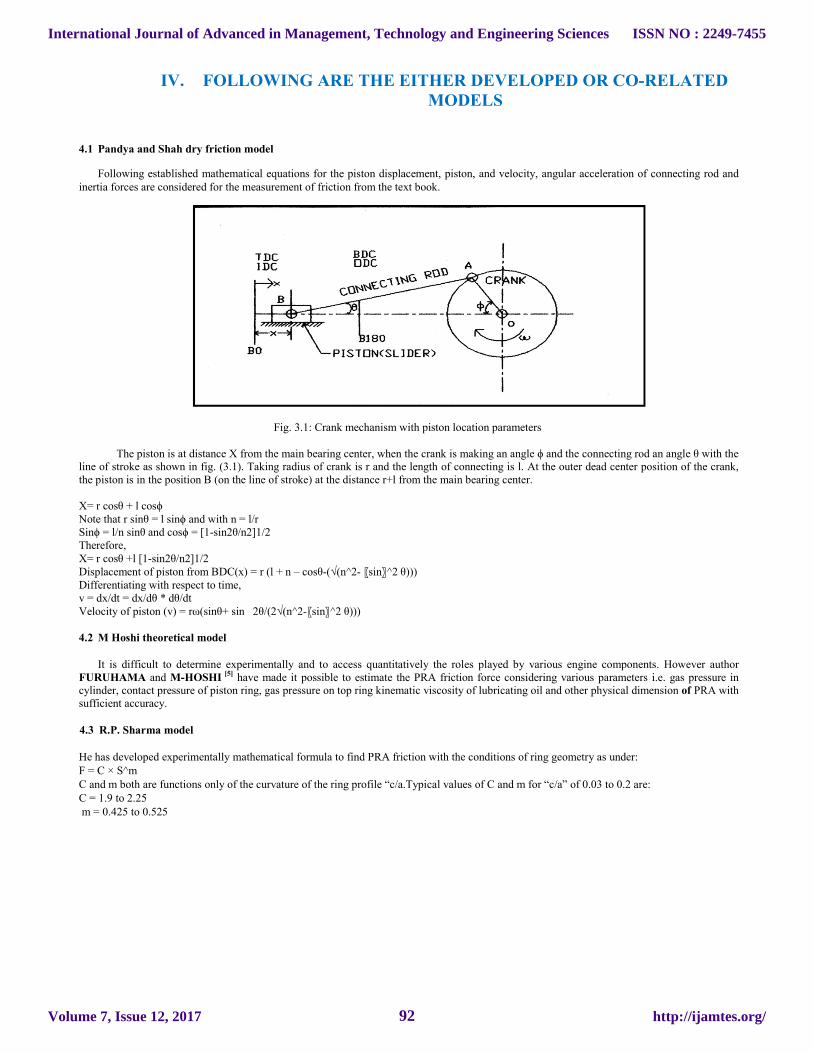
4.1 Pandya and Shah dry friction model
Following established mathematical equations for the piston displacement, piston, and velocity, angular acceleration of connecting rod and inertia forces are considered for the measurement of friction from the text book.
Fig. 3.1: Crank mechanism with piston location parameters
The piston is at distance X from the main bearing center, when the crank is making an angle ϕ and the connecting rod an angle θ with the line of stroke as shown in fig. (3.1). Taking radius of crank is r and the length of connecting is l. At the outer dead center position of the crank, the piston is in the position B (on the line of stroke) at the distance r+l from the main bearing center.
X= r cosθ + l cosϕ Note that r sinθ = l sinϕ and with n = l/r Sinϕ = l/n sinθ and cosϕ = [1-sin2θ/n2]1/2 Therefore, X= r cosθ +l [1-sin2θ/n2]1/2 Displacement of piston from BDC(x) = r (l + n – cosθ-(√(n^2- 〖sin〗^2 θ))) Differentiating with respect to time, v = dx/dt = dx/dθ * dθ/dt Velocity of piston (v) = rω(sinθ+ sin 2θ/(2√(n^2-〖sin〗^2 θ))) 4.2 M Hoshi theoretical model
It is difficult to determine experimentally and to access quantitatively the roles played by various engine components. However author
FURUHAMA and M-HOSHI [5] have made it possible to estimate the PRA friction force considering various parameters i.e. gas pressure in cylinder, contact pressure of piston ring, gas pressure on top ring kinematic viscosity of lubricating oil and other physical dimension of PRA with sufficient accuracy.
4.3 R.P. Sharma model
He has developed experimentally mathematical formula to find PRA friction with the conditions of ring geometry as under: F = C × S^m C and m both are functions only of the curvature of the ring profile “c/a.Typical values of C and m for “c/a” of 0.03 to 0.2 are: C = 1.9 to 2.25 m = 0.425 to 0.525
International Journal of Advanced in Management, Technology and Engineering Sciences
Volume 7, Issue 12, 2017
ISSN NO : 2249-7455
http://ijamtes.org/92

V. COMPARISION OF ENGINE PARAMETERS
Table 2 .The Co- relation of Yukio model with Sharma model
Graph 5.1
Graph 5.2
Graph 5.3
012345
FF (
N)
N(RPM)
RPM VS. FRICTION- 100 CC- SAE 30 OIL-A RING
HOSHI
YUKIO
SHARMA
012345
FF (
N)
N(RPM)
RPM VS. FRICTION- 100 CC- SAE15W40 OIL-A RING
HOSHI
YUKIO
SHARMA
012345
FF(N
)
N(RPM)
RPM VS. FRICTION- 100 CC- 2T OIL-A RING
HOSHI
YUKIO
SHARMA
Value of constant ‘cl’ For SAE30, SAE15W40 and 2T oil
Engine oil 150cc 100cc 80cc 60cc
SAE30 2.3646 2.6956 3.0632 2.5887
SAE15W40 2.3564 2.6867 3.0532 2.5815
2T 2.3540 2.6832 3.0489 2.5777
International Journal of Advanced in Management, Technology and Engineering Sciences
Volume 7, Issue 12, 2017
ISSN NO : 2249-7455
http://ijamtes.org/93
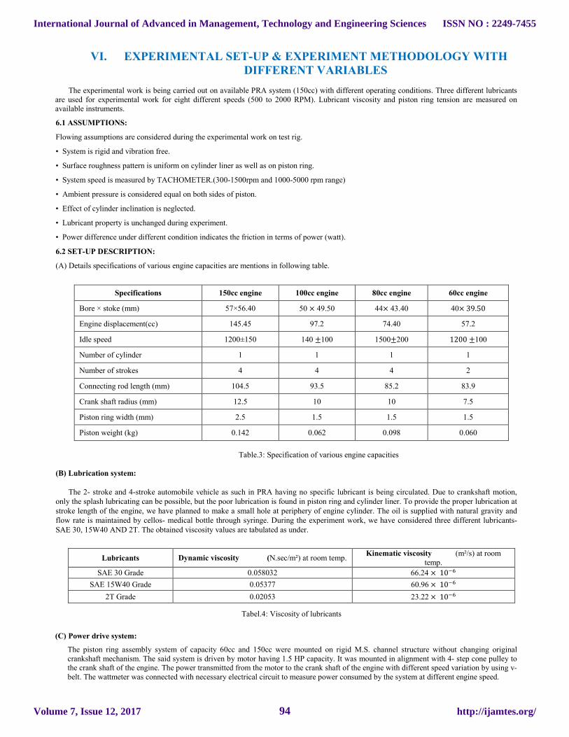
VI. EXPERIMENTAL SET-UP & EXPERIMENT METHODOLOGY WITH DIFFERENT VARIABLES
The experimental work is being carried out on available PRA system (150cc) with different operating conditions. Three different lubricants
are used for experimental work for eight different speeds (500 to 2000 RPM). Lubricant viscosity and piston ring tension are measured on available instruments.
6.1 ASSUMPTIONS:
Flowing assumptions are considered during the experimental work on test rig.
• System is rigid and vibration free.
• Surface roughness pattern is uniform on cylinder liner as well as on piston ring.
• System speed is measured by TACHOMETER.(300-1500rpm and 1000-5000 rpm range)
• Ambient pressure is considered equal on both sides of piston.
• Effect of cylinder inclination is neglected.
• Lubricant property is unchanged during experiment.
• Power difference under different condition indicates the friction in terms of power (watt).
6.2 SET-UP DESCRIPTION:
(A) Details specifications of various engine capacities are mentions in following table.
Specifications 150cc engine 100cc engine 80cc engine 60cc engine
Bore × stoke (mm) 57×56.40 50 × 49.50 44× 43.40 40× 39.50
Engine displacement(cc) 145.45 97.2 74.40 57.2
Idle speed 1200±150 140 ±100 1500±200 1200 ±100
Number of cylinder 1 1 1 1
Number of strokes 4 4 4 2
Connecting rod length (mm) 104.5 93.5 85.2 83.9
Crank shaft radius (mm) 12.5 10 10 7.5
Piston ring width (mm) 2.5 1.5 1.5 1.5
Piston weight (kg) 0.142 0.062 0.098 0.060
Table.3: Specification of various engine capacities
(B) Lubrication system:
The 2- stroke and 4-stroke automobile vehicle as such in PRA having no specific lubricant is being circulated. Due to crankshaft motion, only the splash lubricating can be possible, but the poor lubrication is found in piston ring and cylinder liner. To provide the proper lubrication at stroke length of the engine, we have planned to make a small hole at periphery of engine cylinder. The oil is supplied with natural gravity and flow rate is maintained by cellos- medical bottle through syringe. During the experiment work, we have considered three different lubricants-SAE 30, 15W40 AND 2T. The obtained viscosity values are tabulated as under.
Tabel.4: Viscosity of lubricants
(C) Power drive system:
The piston ring assembly system of capacity 60cc and 150cc were mounted on rigid M.S. channel structure without changing original crankshaft mechanism. The said system is driven by motor having 1.5 HP capacity. It was mounted in alignment with 4- step cone pulley to the crank shaft of the engine. The power transmitted from the motor to the crank shaft of the engine with different speed variation by using v- belt. The wattmeter was connected with necessary electrical circuit to measure power consumed by the system at different engine speed.
Lubricants Dynamic viscosity (N.sec/m²) at room temp. Kinematic viscosity (m²/s) at room
temp.
SAE 30 Grade 0.058032 66.24 × 10��
SAE 15W40 Grade 0.05377 60.96 × 10��
2T Grade 0.02053 23.22 × 10��
International Journal of Advanced in Management, Technology and Engineering Sciences
Volume 7, Issue 12, 2017
ISSN NO : 2249-7455
http://ijamtes.org/94

(D)Test parameters:
• A 60 cc and 150cc engine system on which the test parameters are considered. First speed variation in the range of 500 to 2000rpm in step of increment of 250rpm.
• The second test parameter was considered as piston ring geometry. After survey from the market, the piston ring is available with the flat face. We had provided different chamfering angle on both sides of the piston rings in the range of 15°, 20°and 25° with increment of 5°.
All detail of the piston ring geometries are mention in following table.
Profile Ring type Angle (�) a b c c/a
Flat A 0° - 1.5 - -
Both side chamfer B 15° 0.363 0.5 1.00 2.75
Both side chamfer C 20° 0.87 0.5 1.05 1.21
Both side chamfer D 25° 1.5 1.0 0.75 0.5
(E) Steps of experiment: Following step-by-step procedure was conducted during the experimental work. • First of all a piston ring set was mounted around the piston. • Then checked the alignment of piston and cylinder to maintain proper clearance between them. • After that all electrical connections are checked including wattmeter, speed varial etc. • Initially, the system was run for at least 5 minutes, so that the system get stabilize and lubricating oil can reach properly up the surface of the cylinder liner and piston rings. • After getting the stable condition of the system, record the actual power consumed by wattmeter. • Then switch off the power supply and allow the system to come in rest condition. • Motor was stopped at every observation for changing the speed i.e. 500,750,1000,1250,1500,1750,2000, rpm • Change the speed and lubrication at regular interval of time. • Repeat all the above steps to measure power for given piston ring geometry • The net power consumption for each ring geometry was calculated by subtracting the reading recorded by the wattmeter with and without piston ring. • Finally, total 84 numbers of observations are recorded for each test rig.
International Journal of Advanced in Management, Technology and Engineering Sciences
Volume 7, Issue 12, 2017
ISSN NO : 2249-7455
http://ijamtes.org/95

VII.
Fig.2: Measurement of Engine Speed with TACHOMETER at Motor Shaft
VII. PICTORIAL VIEW OF PROJECT
FIG. 1.A Setup of 60cc Engine
Measurement of Engine Speed with TACHOMETER at Motor Shaft
International Journal of Advanced in Management, Technology and Engineering Sciences
Volume 7, Issue 12, 2017
ISSN NO : 2249-7455
http://ijamtes.org/96
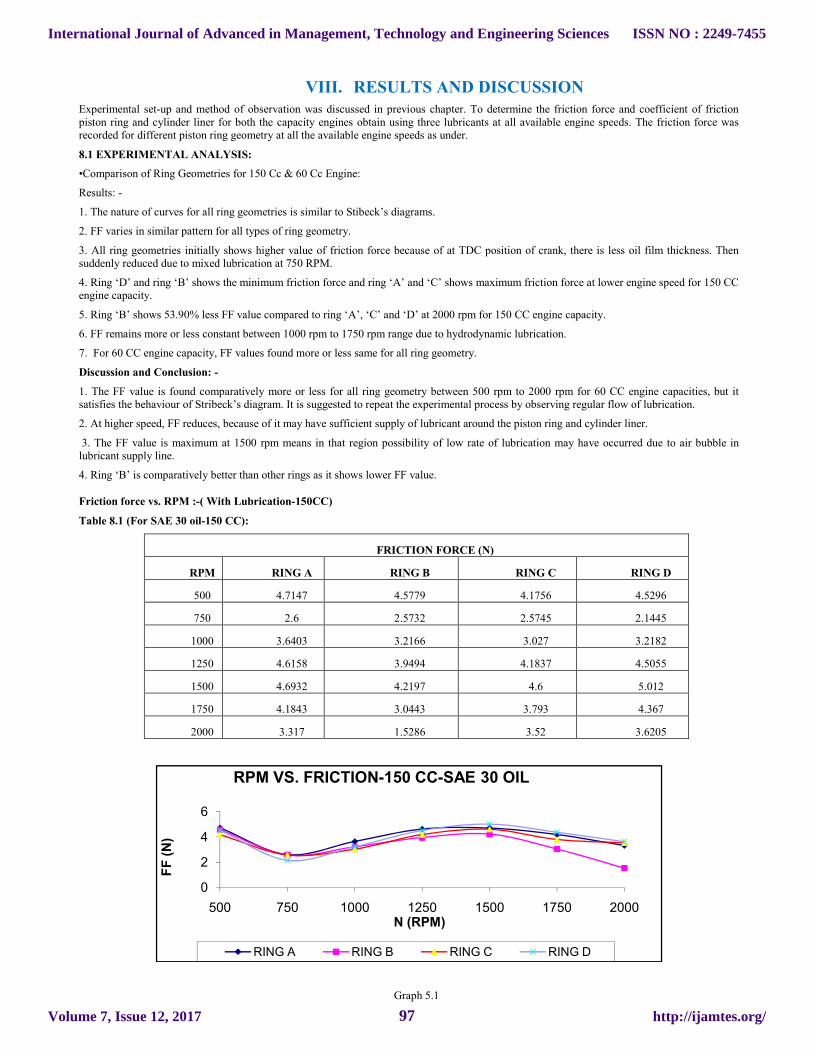
VIII. RESULTS AND DISCUSSION Experimental set-up and method of observation was discussed in previous chapter. To determine the friction force and coefficient of friction piston ring and cylinder liner for both the capacity engines obtain using three lubricants at all available engine speeds. The friction force was recorded for different piston ring geometry at all the available engine speeds as under.
8.1 EXPERIMENTAL ANALYSIS:
•Comparison of Ring Geometries for 150 Cc & 60 Cc Engine:
Results: -
1. The nature of curves for all ring geometries is similar to Stibeck’s diagrams.
2. FF varies in similar pattern for all types of ring geometry.
3. All ring geometries initially shows higher value of friction force because of at TDC position of crank, there is less oil film thickness. Then suddenly reduced due to mixed lubrication at 750 RPM.
4. Ring ‘D’ and ring ‘B’ shows the minimum friction force and ring ‘A’ and ‘C’ shows maximum friction force at lower engine speed for 150 CC engine capacity.
5. Ring ‘B’ shows 53.90% less FF value compared to ring ‘A’, ‘C’ and ‘D’ at 2000 rpm for 150 CC engine capacity.
6. FF remains more or less constant between 1000 rpm to 1750 rpm range due to hydrodynamic lubrication.
7. For 60 CC engine capacity, FF values found more or less same for all ring geometry.
Discussion and Conclusion: -
1. The FF value is found comparatively more or less for all ring geometry between 500 rpm to 2000 rpm for 60 CC engine capacities, but it satisfies the behaviour of Stribeck’s diagram. It is suggested to repeat the experimental process by observing regular flow of lubrication.
2. At higher speed, FF reduces, because of it may have sufficient supply of lubricant around the piston ring and cylinder liner.
3. The FF value is maximum at 1500 rpm means in that region possibility of low rate of lubrication may have occurred due to air bubble in lubricant supply line.
4. Ring ‘B’ is comparatively better than other rings as it shows lower FF value.
Friction force vs. RPM :-( With Lubrication-150CC)
Table 8.1 (For SAE 30 oil-150 CC):
FRICTION FORCE (N)
RPM RING A RING B RING C RING D
500 4.7147 4.5779 4.1756 4.5296
750 2.6 2.5732 2.5745 2.1445
1000 3.6403 3.2166 3.027 3.2182
1250 4.6158 3.9494 4.1837 4.5055
1500 4.6932 4.2197 4.6 5.012
1750 4.1843 3.0443 3.793 4.367
2000 3.317 1.5286 3.52 3.6205
Graph 5.1
0
2
4
6
500 750 1000 1250 1500 1750 2000
FF
(N
)
N (RPM)
RPM VS. FRICTION-150 CC-SAE 30 OIL
RING A RING B RING C RING D
International Journal of Advanced in Management, Technology and Engineering Sciences
Volume 7, Issue 12, 2017
ISSN NO : 2249-7455
http://ijamtes.org/97
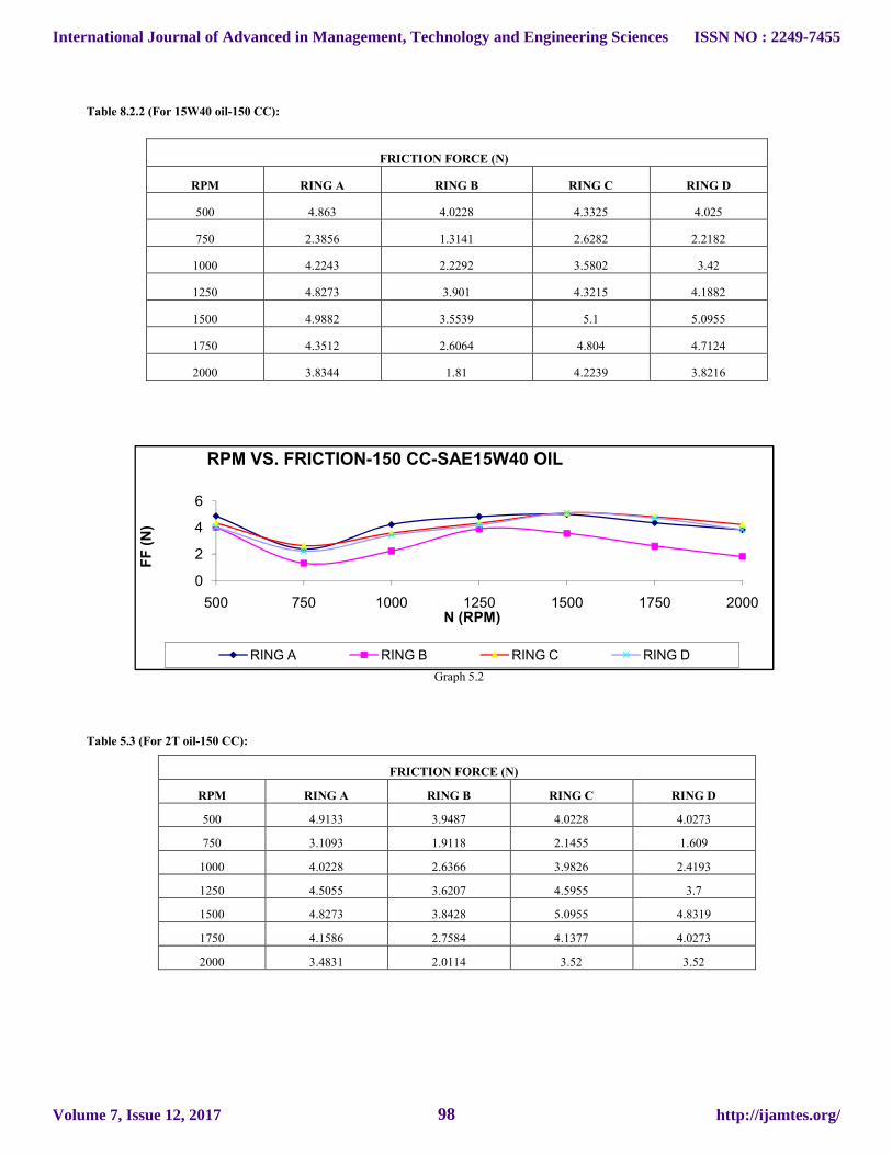
Table 8.2.2 (For 15W40 oil-150 CC):
FRICTION FORCE (N)
RPM RING A RING B RING C RING D
500 4.863 4.0228 4.3325 4.025
750 2.3856 1.3141 2.6282 2.2182
1000 4.2243 2.2292 3.5802 3.42
1250 4.8273 3.901 4.3215 4.1882
1500 4.9882 3.5539 5.1 5.0955
1750 4.3512 2.6064 4.804 4.7124
2000 3.8344 1.81 4.2239 3.8216
Graph 5.2
Table 5.3 (For 2T oil-150 CC):
FRICTION FORCE (N)
RPM RING A RING B RING C RING D
500 4.9133 3.9487 4.0228 4.0273
750 3.1093 1.9118 2.1455 1.609
1000 4.0228 2.6366 3.9826 2.4193
1250 4.5055 3.6207 4.5955 3.7
1500 4.8273 3.8428 5.0955 4.8319
1750 4.1586 2.7584 4.1377 4.0273
2000 3.4831 2.0114 3.52 3.52
0
2
4
6
500 750 1000 1250 1500 1750 2000
FF
(N
)
N (RPM)
RPM VS. FRICTION-150 CC-SAE15W40 OIL
RING A RING B RING C RING D
International Journal of Advanced in Management, Technology and Engineering Sciences
Volume 7, Issue 12, 2017
ISSN NO : 2249-7455
http://ijamtes.org/98

Graph 5.3
IX. CONCLUSION AND SCOPE OF FUTURE WORK In present work we have considered to measure the friction force of a single cylinder I.C. engine of 150 CC. Further we have change the ring geometry and lubricating oils and obtained the performance of the engine. The following overall conclusions are derived.
Overall Conclusions: -
I. Theoretical models:
1. All theoretical models have offered FF value in increasing order with engine speed
2. Hoshi model shows higher FF value compared to Sharma and Yukio models.
3. 2T oil offered lower FF value at all engine speeds compared to SAE 30 and 15W40 oils.
4. During comparison of engine capacity, Hoshi model shows more difference in FF value compared to Yukio and Sharma model.
5. Sharma model and 2T oil are better as both have offered lower FF value at all engine speeds.
6. All the theoretical models show non-uniform gap in FF value under different lubricating oils and ring geometries.
7. A system constant is developed for Yukio model with respect to Hoshi model and Sharma model as shown in table 7.1 and 7.2 respectively. So, all theoretical models can be applied for any engine system.
8. In case of comparing theoretical models results for different lubricating oils, the ring chamfering angle does not play an important role in friction force, i.e. it shows almost same FF value, but coefficient of friction value is increased as per following table. In table 7.3, values are shown for 100 CC single cylinders S.I. engine at 500 rpm for Hoshi model. The friction force value is almost same for all ring type for lubricating oils.
II. FDM solution:
1. To calculate PRA friction force, FDM approach is best compared to all theoretical models as it offered the lowest FF value.
2. For all lubricating oils, FDM shows higher FF value for 150 CC engine capacity compared to other engine capacity because of more surface contact and 60 CC engine capacity shows lower FF value due to less surface contact.
3. For verification, it is better to compare FDM results with Sharma model results as FDM and Sharma model results are matched with each other.
4. As viscosity of 2T oil as about 2.5 times less to SAE 30 oil, FF value for 2T oil is almost 65% that of for SAE 30 and 15W40 oils means higher viscosity oil gives higher FF value.
5. In case of FDM solution, the ring chamfer angle plays important role in FF value and coefficient of friction as per following table. From table 7.4, a major difference was found in friction force and coefficient of friction between ‘A’ rings and ‘B’ ring.
III-Experimental results: 1. Ring geometry ‘B’ is comparatively better than other ring geometry as it has offered lower FF value. 2. Refer graphs no.5.33 to 5.36, indicates that the system is working under hydrodynamic lubrication if compared with Hoshi and Yukio models, but in comparison with Sharma model, it can be said that the system operates under boundary, mixed to hydrodynamic lubrication. Thus, Sharma model values are closer to experimental value. 3. Lubricating oils having lower viscosity shown reasonable good results at lower chamfer angle of piston rings.
RPM VS. FRICTION-150 CC-2T OIL
0
1
2
3
4
5
6
500 750 1000 1250 1500 1750 2000
N (RPM)
FF
(N
)
RING A RING B RING C RING D
International Journal of Advanced in Management, Technology and Engineering Sciences
Volume 7, Issue 12, 2017
ISSN NO : 2249-7455
http://ijamtes.org/99
4. The flat ring geometry of piston ring shown not satisfactory performance because of convergent shape is not form. The chamfer angle of the piston ring has reduced the friction force. 5. Ring Geometry (by keeping the same materials) plays an important role in friction contribution for different type of lubricating engine oil for different engine capacities. 6. Following table shows comparative performance of all rings with three lubricating oils at seven engine speeds. Scope of Future Work: - Due to time constrain of semester, it was not possible to repeat the test cycle for confirmation of experimental results. But it has shown similar percentage difference as per the past experimented results on ring geometry ‘D’ (250 chamfer both side). It is suggested to study further on the same test rig as a scope of future work as under: 1. To study the effect of chamfering angle on piston ring in increment of 50 from 50 to up to 450 (one side and both side) to refine the nature of obtained results curve. 2. By using sophisticated digital instrument to measure oil film thickness experimentally and compared with different theoretical models. 3. It is also suggested to experiment different available automotive lubricants on different S.I. Engine capacities. 4. To provide coating material for piston ring set and cylinder liner in order to reduced friction force and coefficient of friction. 5. The availability of different engine speeds is 500 to 2000 in step of increment 250 rpm. Hence, increase of speed availability is made available in an incremental step of 100 rpm till more precise results could be made available. 6. Improve the properties of lubricating oils by adding the lubricating additives like ZDDP and MODTC in proper ratio. 7. To optimized the chamfer angle for piston ring to obtain minimum value of friction force and coefficient of friction. 8. To develop the motored driven test ring for single cylinder 80 CC and 100 CC engine capacity. 9. Repeat the test cycles with the same parameters to confirm the achieved results. 10. To develop the motored driven test ring for single cylinder 80cc and 100 cc engine capacity. EXPERIMENTAL SAMPLE CALCULATION: [I] FOR 60 CC ENGINE: The sample calculation for measuring friction Force only because of piston ring sliding in the cylinder liner for “TYPE-A” ring using SAE 30 Grade oil at 500 RPM is given below: Net power consumed to drive the PRA system = (Power required to drive with ring) – (Power required to drive without ring) Net power consumed to drive the PRA system = 3.843 watts As, we know that, OR = 3.843 * 60/ (2* π *500) = 0.07342 Nm Now, Where F = friction force r = Crank radius OR = 0.07342/0.0384 Therefore F = 1.9118 N/ring Now, Piston Ring Tension on Liner for one Ring (W) = 10.5 N Therefore, Co-efficient of friction = 1.9118/10.05 µ = 0.182
International Journal of Advanced in Management, Technology and Engineering Sciences
Volume 7, Issue 12, 2017
ISSN NO : 2249-7455
http://ijamtes.org/100

REFERENCES [1]John B. Haywood, “A TB of Internal Combustion Engine Fundamentals (Automotive Technology Series)”, Mcgraw-Hills Book Company, New York, 1998, Pp-712-747. [2]C.M.Tayor, “Automobile Engine Tribology – Design Consideration for Efficiency & Durability “, Elseview Science, Wear 221 (1998) Pp1-8. [3]Bharat Bhushan “Principles and Application of Tribology”, A Wiley- Interscience Publication, John Wiley & Sons, INC, New York, 1999, Pp, Vii-Xix and 1-8. [4]Dr.D.V.Bhatt, Phd Thesis “Performance Study of Tribology Parameter Parameters of A Single Cylinder 2 Stroke Petrol Engine” S.G.University, 2003. . [5]M-HOSHI-Reducing Friction Losses in Automobile Engine-Tribology International-Vol.17, No.4, August 1984 Pp 185-189. [6]Riaz A. Mufti and M. Priest-“Experimental Evaluation of Piston Assembly Friction under Motored and Fired Conditions in a Gasoline Engine”, ASME J. Of Trib. Vol. 127, October 2005. [7]B.J.Taylor and T.S Eyre-“A Review of Piston Ring and Cylinder Liner Materials, Tribology International, April 1979, Pp 79-89. [8]Peter Anderson and Etc., “Piston Ring Tribology- A Literature Survey”, Espoo 2002, VTT Tiedotteita, 105 Pp. [9]V.Ganesan-“I.C.Engine”, Tata Mcgraw-Hill Publishing Company Ltd. New Delhi, 2006. [10]A. Domkundwar & V. Domkundwar – A Course In I.C Engine- Dhanpatrai & Co.(Pvt) Ltd- 2006 [11]R.I.Taylor, Lubricant, Tribology and Motorsport, Shell Globe Solution (UK), 2002-01-3355, Pp- 1-16. [12]Yukio Tateshi-Tribological Issues In Reducing Piston Ring Friction Losses-Tribology International Vol127-1994. [13] R.P. Sharma, Technical Advisor, Mahindra & Mahindra “Practical Consideration in Engine Tribology” Proceedings of Workshop in Current Trends in I.C Engine Development- April-2003-Hyderabad. [14]R.I. Taylor, “Engine Friction Lubricant Sensitive’s: A Comparison of Modern Diesel and Gasoline Engines”, Shell Research & Technology Centre, Thorton, U.K. Pp-1-5. [15]R.C. Coy-‘Practical Applications of Lubrications Model In Engines’, Tribology International.Vol.31, No.10, pp 563-571, 1998. [16]Simon C. Tung and Hong Gao, “Automotive Tribology Overview Of Current Advances And Challenges For The Future’, Tribology International 37 (2004) Pp517-536.
[17]Mike T, Noorman. “Overview Techniques For Measuring Friction Using Bench Test And Fired Engines”, SAE International, June 2000, pp 1-11. [18]D.E. Richardson,” Review of Power Cylinder Friction for Diesel Engines”, SAE Paper 852355, 1985. [19]Ting L.L.-“A Review of Present Information on Piston Ring Tribology”, SAE Paper 852355, 1985. [20]Ozen Aklin And Golam M.Newaz “Piston Ring-Cylinder Bore Friction Modelling In Mixed Lubrication Regime: Part II-Correlation With Bench Test Data” ASME Journal Of Tribology, Vol.223, Pp 219-223, 2001. [21]Jhon J. Truhan, Jun Qu, Peter J. Blau –“The Effect Of Lubricating Oil Condition On The Friction And Wear Of Piston Ring And Cylinder Liner Materials In A Reciprocating Bench Test” Wear, 259 (2005) Pp 1048-1055. [22]M. Ma, I. Sherrington, E.H. Smith, “Analysis of Lubrication and Friction for A Complete Piston-Ring Pack with an Improved Oil Availability Model”, Proc. Of The Insct. Of Mech. Engineers, Part J, Journal of Engineering Tribology, Vol. 211, No. 1/1997, Pp 1-15.
International Journal of Advanced in Management, Technology and Engineering Sciences
Volume 7, Issue 12, 2017
ISSN NO : 2249-7455
http://ijamtes.org/101

[23]Akuri T. Hamatake, M. Soejima & T. Kithahare-Piston Ring Friction in I.C. Engine Tribology International Vol25, No.5, Pp 299-308, 1992. [24]Victor W.Wong (Principal Investgeter, MIT) “Low Engine Friction Technology For Advanced Natural Gas Reciprocating Engines” Advanced University Reciprocating Engine Program, Annual Reveiw Meeting, July 12, 2005, Argonne, IL, Pp 1-62. [25]N.W. Bolander, B.D. Steenwyk, F Sadeghi And G.R. Gerber, “Lubrication Regime Transitions At The Piston Ring- Cylinder Liner Interface”, J Of Engineering Tribology. Proc. Imeche Vol. 219, Part J, 2005 Pp19-31. [26]P.C. Nautiyal, S. Singhal and J.P. Sharma “Friction and Wear Processes in Piston Rings” Tribology International, 1983, Pp 43-49. [27]D. V. Bhatt& Dr. K.N. Mistry “Friction Measurement in Reciprocating System. A Case Study- IPROMM -2000 WORKSHOP, 19-20 Jan-2001. Nagpur. [28]N.C. Pandya and C.S. Shah “Theory of Machine” Vol-1. [29]J. Halling “Principles Of Tribology” Printed In Hong Kong By Wing Kwing Tong Co. Ltd.-1978. [30]A. Cameron “Basic Lubrication Theory” -3 Edition.Wiley Meastern Limited. New Delhi, 1981.
International Journal of Advanced in Management, Technology and Engineering Sciences
Volume 7, Issue 12, 2017
ISSN NO : 2249-7455
http://ijamtes.org/102


![PISTON TECH - materion.com · material, piston material [or ring groove] and the piston liner and its surface treatment.” 1. A 3D illustration of a piston ring motion 2. With a](https://static.fdocuments.us/doc/165x107/5fcadda8a379fe5ba73c99c0/piston-tech-material-piston-material-or-ring-groove-and-the-piston-liner-and.jpg)