TheMITC9 shell elementin plate bending ...
22
The MITC9 shell element in plate bending: mathematical analysis of a simplified case Klaus-J¨ urgen Bathe 1 , Franco Brezzi 2,3 , L. Donatella Marini 4,2 Abstract We consider the 9-node shell element referred to as the MITC9 shell element in plate bending solutions and present a simplified mathematical analysis. The element uses bi-quadratic interpolations of the rotations and transverse displacement, and the ”rotated Raviart-Thomas” interpolations for the transverse shear stresses. A rigorous mathematical analysis of the element is still lacking, even for the simplified case of plate solutions (that is, flat shells), although the numerical evidence suggests a good and reliable behavior. Here we start such an analysis by considering a very simple particular case; namely, a rectangular plate, clamped all around the boundary, and solved with a uniform decomposition. Moreover, we consider only the so-called limit case, corresponding to the limit equations that are obtained for the thickness t going to zero. While the mathematical analysis of the limit case is simpler, such analysis, in general, gives an excellent indication of whether shear locking is present in the real case t> 0. We detail that the element in the setting considered shows indeed optimal behavior. 1 Introduction Numerous finite elements based on Kirchhoff plate theory and Reissner-Mindlin plate theory have been proposed for linear plate analyses, see for example [1, 2]. Today, plate bending elements are available that have been proven to be optimal by mathematical 1 MIT, Department of Mechanical Engineering, Massachusetts Institute of Technology, Cambridge, MA 02139 USA 2 IMATI del CNR, Via Ferrata 5/A, 27100 Pavia, Italy 3 IUSS, Lungoticino Sforza 56, 27100 Pavia, Italy 4 Dipartimento di Matematica, Universit` a di Pavia, Via Ferrata 5/A, 27100 Pavia, Italy 1
Transcript of TheMITC9 shell elementin plate bending ...

The MITC9 shell element in plate bending: mathematical analysis of asimplified case
Klaus-Jurgen Bathe1, Franco Brezzi2,3, L. Donatella Marini4,2
Abstract
We consider the 9-node shell element referred to as the MITC9 shell element inplate bending solutions and present a simplified mathematical analysis. The elementuses bi-quadratic interpolations of the rotations and transverse displacement, andthe ”rotated Raviart-Thomas” interpolations for the transverse shear stresses. Arigorous mathematical analysis of the element is still lacking, even for the simplifiedcase of plate solutions (that is, flat shells), although the numerical evidence suggestsa good and reliable behavior. Here we start such an analysis by considering avery simple particular case; namely, a rectangular plate, clamped all around theboundary, and solved with a uniform decomposition. Moreover, we consider onlythe so-called limit case, corresponding to the limit equations that are obtained forthe thickness t going to zero. While the mathematical analysis of the limit caseis simpler, such analysis, in general, gives an excellent indication of whether shearlocking is present in the real case t > 0. We detail that the element in the settingconsidered shows indeed optimal behavior.
1 Introduction
Numerous finite elements based on Kirchhoff plate theory and Reissner-Mindlin platetheory have been proposed for linear plate analyses, see for example [1, 2]. Today, platebending elements are available that have been proven to be optimal by mathematical
1MIT, Department of Mechanical Engineering, Massachusetts Institute of Technology, Cambridge,MA 02139 USA
2IMATI del CNR, Via Ferrata 5/A, 27100 Pavia, Italy3IUSS, Lungoticino Sforza 56, 27100 Pavia, Italy4Dipartimento di Matematica, Universita di Pavia, Via Ferrata 5/A, 27100 Pavia, Italy
1

2
analysis and have revealed that optimal behavior also in numerical solutions, see e.g. [3]–[6]. Although these elements are available, of course, there is still important research inthe analysis of plates to establish computationally more cost-effective schemes in general,and in particular for composite plate analyses where three-dimensional effects can beimportant.
The situation is quite different in the analysis of shells [7, 8]. Such structures are muchmore difficult to analyze and efficient, reliable, and generally applicable shell elements aremuch more difficult to develop. Indeed, while many shell elements have been proposed,there is still no element available that has been proven mathematically to always performoptimally in all shell analyses and in any mesh used. The reason is that the behavior ofshell structures is greatly affected by the curvature of the shell, the boundary conditions,the thickness, and the loading applied [7]–[10]. Moreover, the limit behaviour of a shell forthe thickness going to zero can show, even in quite realistic cases, a discouraging varietyof patterns that make a unified analysis extremely difficult, see e.g. [11]–[15]. Whilecomplete convergence proofs are very difficult to achieve, and indeed still out of reach,it is important to recognize that mathematical analysis has been extremely valuable toestablish discriminating numerical tests with error norms to identify the value of a shellsolution scheme [8, 16, 17].
A simple shell in bending is of course a flat plate, and in practical finite elementanalyses it is common practice to use shell elements for plate solutions [1, 2, 18, 19, 20].There are at least two reasons. First, in practice, plates are frequently encountered incomplex structures, like in facetted configurations, with beams to act as stiffeners, orwith attached cables (e.g. in a suspension bridge). In these cases, the membrane in-planeactions, like in a general shell, are very important. Second, if an originally flat plateundergoes large displacements, a full shell behavior is encountered. Hence, if an originallyflat thin structure has been modeled using shell elements, a large displacement analysiscan directly be pursued with the same finite element model. Therefore, ideally, we wouldhave general shell elements that for plate bending analyses show optimal behavior, justlike the optimal plate elements referred to above.
Based on these thoughts, the quadratic MITC shell elements were tested for theirbehavior in plate analyses [21]. Specifically, the numerical performance of the MITCshell elements, developed for general shell analyses, was compared with the performanceof the MITC plate elements, designed for the linear analysis of plates and known to yieldoptimal solutions. An interesting conclusion was that the MITC9 shell element of ref. [22],based on the earlier element given in ref. [23], performed as well as the MITC9 plateelement of refs. [3, 5]. We show these results in Figures 1.1 and 1.2. However, whereasthe plate element has a strong mathematical foundation, the shell element was proposedbased only on physical insight, mathematical conditions, and numerical experiments. A

3
mathematical analysis of this element in complex shell analyses was out of reach.Clearly, a general mathematical analysis of the MITC9 shell element would be ex-
tremely valuable. However, it is already an important step to mathematically analyzethe element when considering plate bending solutions only. Our objective in this paperis to detail such an analysis. We use a simplified setting to focus on the basic behaviorof the element. The mathematical analysis shows that the convergence of the element isindeed optimal – hence, that the numerical results in ref. [21] should be expected.
The given analysis and results are valuable because the mathematical proofs givestrength to the numerical findings, and the analysis yields insight that may provide abasis for more comprehensive mathematical studies of the element, also directed to thesolution of complex shell structures.
In the paper, we will use the notation A � B whenever there exists a constantC, depending only on the ratio of the two edges of the rectangular domain, such thatA ≤ C B. Clearly A � B will be used whenever B � A.
Throughout the paper, for s integer we will denote by Hs(Ω) the usual Sobolev spaceof functions that are square-integrable in Ω together with their (weak) derivatives up tothe order s. We denote by Hs
0(Ω) the subspace of Hs(Ω) made of functions that vanish at
the boundary ∂Ω of Ω together with all their derivatives up to the order s− 1. Moreover‖ ·‖s,Ω or simply ‖ ·‖s will be used to indicate the usual Sobolev norm in Hs(Ω) (or copiesof it). In particular we shall use the notation ‖ · ‖0 and (· , ·)0 for the norm and the scalarproduct (respectively) in L2(Ω) or copies of it.
2 Formulation of the problem and basic notation
In this section we formulate the continuous problem and introduce some required notationfor our analysis.
2.1 The continuous problem
Let Ω be the rectangle ]0, L1[×]0, L2[. Without loss of generality we can assume thatL1 ≤ L2. Introducing the spaces
Θ := (H10 (Ω))
2, W := H10 (Ω), (2.1)
corresponding to hard clamped boundary conditions (see, e.g., [1]), we set
U := Θ×W (2.2)
with the norm‖V ‖2U := ‖η‖21,Ω + ||v||21,Ω for V = (η, v) ∈ U . (2.3)

4
x3
x1
qt
x1
x2
L2
L2
A B
CD
( b )
h
( a )
Figure 1.1: Clamped plate considered and finite element results obtained using the MITC9shell element. (a) Square plate problem solved, uniform pressure is applied, L1 = L2 =L = 1.0, Young’s modulus = 1.7472× 10⁷, Poisson’s ratio = 0.30. (b) Typical mesh usedfor region A-B-C-D, N=4.
We also define, for η ∈ Θ, the symmetric gradient ε(η)
(ε(η))i,j :=1
2
(∂ηi
∂xj
+∂ηj
∂xi
), (2.4)
and for every t > 0 we define the bilinear form At on U ×U , with Young’s modulus equalto 12 and Poisson’s ratio equal to 0, as
At(U, V ) := (ε(θ), ε(η))0 + 6t−2(∇w − θ,∇v − η)0 (2.5)
for U = (θ, w) and V = (η, v). We are interested in the case “t small”. Hence, even whenit is not explicitly specified, we will always consider the case of t being small, certainlyt < L1.
The bending part of the bilinear form At will be usually denoted by Ab, that is
Ab(U, V ) := (ε(θ), ε(η))0. (2.6)
We recall the following well known result (see, e.g., [4, 8]).
Proposition 2.1. The bilinear form At is continuous and elliptic on U × U for everyt > 0, in the sense that: for every t with 0 < t < L1 there exist three positive constantsCt, Cb and Cs such that
At(U, V ) ≤ Ct ‖U‖U ‖V ‖U ∀U, V ∈ U (2.7)

5
t/L = 1/100
t/L = 1/1000
t/L = 1/10000
log( h )
log
(re
lati
ve
err
or
)
-1.5 -1 -0.5 0
-5.5
-5
-4.5
-4
-3.5
-3
-2.5
-2
-1.5
-1
-0.5
0
log( h )
log
(re
lati
ve
err
or
)
-1.5 -1 -0.5 0
-5.5
-5
-4.5
-4
-3.5
-3
-2.5
-2
-1.5
-1
-0.5
0
t/L = 1/100
t/L = 1/1000
t/L = 1/10000
Figure 1.2: Results obtained for the clamped plate using the MITC9 shell element. Left:relative error for rotations in the H1 norm. Right: relative error for transverse displace-ment in the H1 norm. In both cases the slope is 2, as expected.

6
Ab(U, V ) ≤ Cb ‖U‖U ‖V ‖U ∀U, V ∈ U (2.8)
At(V, V ) ≥ Cs‖V ‖2U ∀V ∈ U . (2.9)
Moreover Cb and Cs are independent of t.
Proof. Continuity equations (2.7) and (2.8) are obvious. Next, we recall the Korn in-equality: for V = (η, v) ∈ U
Ab(V, V ) ≡ (ε(η), ε(η))0 � ‖η‖21,Ω, (2.10)
which impliesAt(V, V ) ≥ Ab(V, V ) � ‖η‖21,Ω, (2.11)
and since L1 > t > 0 we obviously have
‖∇v‖20,Ω ≤ 2‖∇v − η‖20,Ω + 2‖η‖20,Ω � At(V, V ), (2.12)
and the result follows from (2.11) and (2.12).
Remark 2.2. For simplicity we assumed in (2.5) Poisson’s ratio equal to 0. However,it is clear that the properties of At and Ab in the above proposition (which we use for allour estimates) do not depend on this assumption.
We now fix a function (load) g ∈ L2(Ω) and define
(G, V )0 := (g, v)0 for V = (η, v), (2.13)
and we note that, obviously,
|(G, V )0| ≤ ‖g‖0 ‖V ‖U . (2.14)
We then consider the problem:{Find U ∈ U such that
At(U, V ) = (G, V )0 ∀V ∈ U . (2.15)
From Proposition 2.1 we have immediately existence and uniqueness of the solution of(2.15).
Proposition 2.3. For every t > 0 and for every g ∈ L2(Ω) problem (2.15) has a uniquesolution U that satisfies
‖U‖U � ‖g‖0. (2.16)
Moreover, U coincides with the unique minimizer on U of the functional
JRMt (V ) :=
1
2At(V, V )− (G, V )0. (2.17)

7
2.2 The Lagrange multipliers formulation
We introduce now the formulation with multipliers. For this we need to define the spaces
H(rot; Ω) := {δ ∈ (L2(Ω))2, such that rotδ ∈ L2(Ω)}, (2.18)
where rotδ, as usual in two-dimensional settings, is defined as rotδ := ∂δ2∂x1
− ∂δ1∂x2
, and
Q := H0(rot; Ω) ≡ {δ ∈ H(rot; Ω) such that, δ · t = 0 on ∂Ω} (2.19)
where t is the unit counterclockwise tangent vector to ∂Ω. We also define the norm
‖δ‖2Q := ‖δ‖20,Ω + ‖rotδ‖20,Ω. (2.20)
We can also define the space of multipliers M as
M := Q′ (2.21)
(that is, the dual space of Q). We shall often use the following notation
L :=(L2(Ω)
)2(2.22)
It is evident that Q ⊆ L with continuous dense embedding so that L (that we identify asusual with its own dual space) can be identified with a dense subspace of M = Q′.
Remark 2.4. It can be proved (see, e.g., [4]) that
M ≡ {μ ∈ (H−1(Ω))2 such that divμ ∈ H−1(Ω)}. (2.23)
It will also be convenient to introduce the operator B : U → Q defined as
B(V ) = ∇v − η for V = (η, v). (2.24)
The following result is well known (see e.g. [4]).
Proposition 2.5. The space Q coincides with the image of U through the operator B.Moreover, for every δ ∈ Q there exists a V ∈ U such that B(V ) = δ and
‖V ‖U � ‖δ‖Q. (2.25)

8
We consider now the saddle-point problem:⎧⎪⎪⎪⎪⎪⎨⎪⎪⎪⎪⎪⎩Find U ≡ (θ, w) ∈ U and λ ∈ L such that
Ab(U, V ) + M< λ, B(V ) >Q= (G, V )0 ∀V ∈ U
M< μ, B(U) >Q −t2
6(λ,μ)0 = 0 ∀μ ∈ L.
(2.26)
As Proposition 2.5 implies the inf-sup condition
∃β > 0 such that infμ∈M
supV ∈U
Q< B(V ),μ >M‖V ‖U ‖μ‖M
≥ β (2.27)
we can easily have the following result.
Proposition 2.6. For every t > 0 and for every g ∈ L2(Ω), problem (2.26) has a uniquesolution (U,λ) that satisfies
‖U‖U + ‖λ‖M � ‖g‖0. (2.28)
Moreover, U coincides with the solution of (2.15).
Proof. The result is rather classical, but we summarize the proof for the convenienceof the reader. Let us first consider, for every t > 0, the solution U of (2.15), and setλ := 6t−2B(U) that belongs to Q ⊂ L. It is easy to see that the pair (U,λ) is a solutionof (2.26). Moreover the first part of (2.28), that is
‖U‖U � ‖g‖0, (2.29)
holds true due to (2.16). Finally, from (2.27) we immediately have that
∃V ∗ ∈ U such that ‖λ‖M ≤ 1
βQ< B(V ∗),λ >M
‖V ∗‖U, (2.30)
and using the first equation of (2.26) with V = V ∗, and then (2.14) and (2.8), we have
‖λ‖M ≤ 1
β
(G, V ∗)0 −Ab(U, V∗)
‖V ∗‖U� (‖g‖0 + ‖U‖U), (2.31)
and the result follows from (2.29) and (2.31).
Remark 2.7. In mathematical terms, problem (2.26) is singularly perturbed, since, fora general G ∈ U ′ and a general Lipschitz domain, its solution (U(t),λ(t)) exists in U ×Lfor every t > 0, but is not uniformly bounded in U × L. However, U(t) is uniformlybounded in U , and the inf-sup condition (2.27) provides a uniform bound for λ(t) in M(although not in L).

9
2.3 The limit problem
As the bound in (2.28) does not depend on t (and U and M are Hilbert spaces), it iseasy to see and well known (see e.g. [4], Theorem VII.3.1) that U = U(t) and λ = λ(t)have a limit for t → 0.
Proposition 2.8. For every g ∈ L2(Ω) we have
limt→0
(U(t),λ(t)) = (U0, λ0) (2.32)
where (U0, λ0) is the unique solution of the limit problem⎧⎪⎪⎪⎪⎨⎪⎪⎪⎪⎩Find U0 ≡ (θ0, w0) ∈ U and λ0 ∈ M such that
Ab(U0, V ) + M< λ0, B(V ) >Q= (G, V )0 ∀V ∈ U
M< μ, B(U0) >Q= 0 ∀μ ∈ M.
(2.33)
Moreover, θ0 = ∇w0 and w0 is the solution of the (Kirchhoff-like) problem
Δ2w0 = g in Ω, w0 = 0 and∂w0
∂n= 0 on ∂Ω. (2.34)
It is immediate to see that, introducing the linear space
Z = {V = (v,η) ∈ U such that η = ∇v}, (2.35)
problem (2.33) is equivalent to{Find U0 ∈ Z such that
Ab(U0, V ) = (G, V )0 ∀V ∈ Z (2.36)
in the sense that: if (U0,λ0) solves (2.33) then U0 solves (2.36).
We shall focus on this limit problem in our convergence analysis of the MITC9 shellelement. This analysis is tractable and will give a strong indication on whether theelement is shear-locking or not when solving this problem using the specified uniformdecompositions.
Figures 2.1 and 2.2 give the profiles of the transverse displacement of the plate alongits midline, as calculated using the MITC4 shell element – which is in this solution

10
x
No
rmalized
tran
svers
ed
isp
lacem
en
t
MITC4, N=4
0 0.2 0.4 0.6 0.8 1
-1.4
-1.2
-1
-0.8
-0.6
-0.4
-0.2
0
t/L = 1/10
t/L = 1/100
t/L = 1/1000
t/L = 1/1000000
x
No
rmalized
tran
svers
ed
isp
lacem
en
t
MITC4, N=16
0 0.2 0.4 0.6 0.8 1
-1.4
-1.2
-1
-0.8
-0.6
-0.4
-0.2
0
t/L = 1/10
t/L = 1/100
t/L = 1/1000
t/L = 1/1000000
x
No
rmalized
tran
svers
ed
isp
lacem
en
t
MITC4, N=32
0 0.2 0.4 0.6 0.8 1
-1.4
-1.2
-1
-0.8
-0.6
-0.4
-0.2
0
t/L = 1/10
t/L = 1/100
t/L = 1/1000
t/L = 1/1000000
Figure 2.1: The displacement along the mid-line of the plate of Fig. 1.1 is shown for N=4,16, 32 and different values of plate thickness for the MITC4 element; the normalizingfactor is q/(108 ∗ t3). For t/L smaller than 1/100 the displacements are practically equalto those of the case t/L = 1/100.

11
x
No
rmalized
tran
svers
ed
isp
lacem
en
t
DISP4, N=4
0 0.2 0.4 0.6 0.8 1
-1.4
-1.2
-1
-0.8
-0.6
-0.4
-0.2
0
t/L = 1/10
t/L = 1/100
t/L = 1/1000
t/L = 1/1000000
x
No
rmalized
tran
svers
ed
isp
lacem
en
t
DISP4, N=16
0 0.2 0.4 0.6 0.8 1
-1.4
-1.2
-1
-0.8
-0.6
-0.4
-0.2
0
t/L = 1/10
t/L = 1/100
t/L = 1/1000
t/L = 1/1000000
x
No
rmalized
tran
svers
ed
isp
lacem
en
t
DISP4, N=32
0 0.2 0.4 0.6 0.8 1
-1.4
-1.2
-1
-0.8
-0.6
-0.4
-0.2
0
t/L = 1/10
t/L = 1/100
t/L = 1/1000
t/L = 1/1000000
Figure 2.2: The displacement along the mid-line of the plate of Fig. 1.1 is shown forN=4,16,32 and different values of plate thickness for the 4-node displacement-based ele-ment, here referred to as DISP4; the normalizing factor is q/(108 ∗ t3). For t/L smallerthan 1/100 the displacements are extremely small.

12
identical to the MITC4 plate element and known to be locking-free [24]– and the 4-nodedisplacement-based element – which is known to severely lock. We see that for the MITC4shell element, the displacements are indistinguishable for the coarse and fine meshes usedwhen t/L = 1/100 and smaller. Shear deformations contribute to the response when theplate is thick. On the other hand, for the displacement-based element, the displacementsbecome rapidly small when the thickness of the plate decreases, that is, the element locks.These numerical results, together with those of Figure 1.2, illustrate that - as expected- in a mathematical analysis it is reasonable to consider the limit problem as a valuableindicator of the performances of an element for thin and moderately thick plates.
3 The discretized problem
We consider now, for simplicity, a sequence of decompositions Th of our domain Ω intorectangles K by means of the points
0 ≡ x0 < x1 < ... < xI ≡ L1 0 ≡ y0 < y1 < ... < yJ ≡ L2 (3.1)
and we set as usual
hx := max0≤i≤I−1
(xi+1 − xi) hy := max0≤j≤J−1
(yj+1 − yj) h := max{hx, hy}. (3.2)
For r and s integers ≥ 0 we define the space Qr,s as the space of polynomials of degree≤ r in x1 and of degree ≤ s in x2. When r = s we will just, as usual, write Qr instead ofQr,r. Then we consider the finite element spaces
Θh := {θ ∈ Θ such that ∀K ∈ Th, θ ∈ Q2(K)}, (3.3)
W h := {v ∈ W such that ∀K ∈ Th, v ∈ Q2(K)}, (3.4)
andMh := {μ such that μ|K ∈ Q1,2 ×Q2,1 ∀K ∈ Th}. (3.5)
Finally, we define the reduction operator Π from (C0(Ω))2 to Mh. For this, on everyinterval (xi, xi+1) we define the midpoint xm
i and the two zeroes of the second degreeLegendre polynomial x�1
i and x�2i ; similarly, for every interval (yj, yj+1) we define the
midpoint ymj and the two zeroes of the second degree Legendre polynomial y�1j and y�2j(see Fig. 3.1). Then, for every χ ∈ (C0(Ω))2 we define Πχ as the unique μ ∈ Mh such

13
2
x x
x
i
i i
i+1
mx 1i x
Figure 3.1: Midpoint and two Gauss points for 2-point integration on an interval.
that (see Fig. 3.2)
μ1(x�1i , yj) = χ1(x
�1i , yj) i = 0, ..., I − 1, j = 0, ..., J
μ1(x�2i , yj) = χ1(x
�2i , yj) i = 0, ..., I − 1, j = 0, ..., J
μ1(x�1i , y
mj ) = χ1(x
�1i , y
mj ) i = 0, ..., I − 1, j = 0, ..., J − 1
μ1(x�2i , y
mj ) = χ1(x
�2i , y
mj ) i = 0, ..., I − 1, j = 0, ..., J − 1
(3.6)
and
μ2(xi, y�1j ) = χ2(xi, y
�1j ) i = 0, ..., I, j = 0, ...J − 1
μ2(xi, y�2j ) = χ2(xi, y
�2j ) i = 0, ..., I, j = 0, ...J − 1
μ2(xmi , y
�1j ) = χ2(x
mi , y
�1j ) i = 0, ..., I − 1, j = 0, ...J − 1
μ2(xmi , y
�2j ) = χ2(x
mi , y
�2j ) i = 0, ..., I − 1, j = 0, ...J − 1
(3.7)
X
X
X X
X
X X
X XX
X X
Figure 3.2: D.o.f. for μ1 (left) and μ2 (right)
It is important to note that for every v ∈ W h we have ∇v ∈ Mh, so that
Π(∇v) = ∇v ∀v ∈ W h. (3.8)
Moreover, owing to the (obvious) continuity of Π in finite dimensional spaces made ofpiecewise smooth functions we easily have
‖Πη‖0 � ‖η‖0 ∀η ∈ Θh (3.9)

14
We can now set Uh := Θh ×W h and consider the discrete problem:⎧⎪⎪⎪⎪⎪⎨⎪⎪⎪⎪⎪⎩Find Uh ≡ (θh, wh) ∈ Uh, and λh ∈ Mh such that
Ab(Uh, V ) + (λh,Π(B(V )))0 = (G, V )0 ∀V ∈ Uh
(μ,Π(B(Uh)))0 −t2
6(λh,μ)0 = 0 ∀μ ∈ Mh.
(3.10)
Existence and uniqueness of the solution of the discrete problem for t > 0 follow exactlyas for the continuous problem.
Remark 3.1. The corresponding MITC9-plate element uses the same space Θh as in(3.3), while Wh consists of local 8-node serendipity functions. The space M is moresophisticated: the first component is made of local P2 polynomials without the monomialx2, while the second component is made of local P2 polynomials without the monomial y2
[6]. The analysis (see e.g. [26]) is largely based on the properties of the Q2 − P1 Stokeselement. The operator Π uses, for each component, the average over the element domaininstead of the two internal stations shown in Figure 3.2.
We now consider and analyze the limit problem of (3.10) for t → 0. Introducingthe subspace
Zh = {V = (v,η) ∈ Uh such that Π(η) = ∇v}, (3.11)
it is immediate to see that, for t → 0, Uh(t) converges to the solution Uh0 of the limit
problem {Find Uh
0 ∈ Zh such that
Ab(Uh0 , V ) = (G, V )0 ∀V ∈ Zh,
(3.12)
that can be obviously seen as a discretization of the continuous limit problem (2.36).Existence and uniqueness of the solution of (3.12) follow immediately from (2.10). Herewe want to study the error ‖U0 − Uh
0 ‖U .We start with the following “abstract” result.
Theorem 3.2. Let (U0,λ0) be the solution of (2.33), and let Uh0 be the solution of (3.12).
Let moreover U I be any element of Zh. Then we have
‖U0 − Uh0 ‖U � ‖U0 − U I‖U + sup
V h∈Zh
(λ0, B(V h)− Π(B(V h)))
‖V h‖U. (3.13)
15
Proof. For all V = (η, v) ∈ Zh we have first, using (2.10)
‖η‖21,Ω � (ε(η), ε(η)) � Ab(V, V ), (3.14)
and using (3.11), (3.9), and (3.14):
|∇v|20,Ω = ‖Π(η)‖20,Ω � ‖η‖20,Ω � Ab(V, V ), (3.15)
so that‖V ‖2U � Ab(V, V ) ∀V ∈ Zh. (3.16)
Now we apply (3.16) to V = Uh0 − U I , then we add and subtract U0, then we use (3.12)
and (2.33) for the first term, and the Cauchy-Schwarz inequality for the second:
‖Uh0 −U I‖2U � Ab(U
h0 −U I , Uh
0 −U I) = Ab(Uh0 −U0, U
h0 −U I) +Ab(U0 −U I , Uh
0 −U I)
� (G,Uh0 − U I)− {(G,Uh
0 − U I)− (λ0, B(Uh0 − U I))}+ ‖U0 − U I‖U ‖Uh
0 − U I‖U= (λ0, B(Uh
0 − U I)) + ‖U0 − U I‖U ‖Uh0 − U I‖U . (3.17)
To treat the first term in the last line of (3.17) we remember that Π(B(Uh0 −U I)) = 0 so
that
|(λ0, B(Uh0 − U I))| = |(λ0, B(Uh
0 − U I)− Π(B(Uh0 − U I)))|
≤(
supV h∈Zh
(λ0, B(V h)− Π(B(V h)))
‖V h‖U
)‖Uh
0 − U I‖U .(3.18)
Inserting (3.18) in (3.17) and simplifying by ‖Uh0 − U I‖U we get the result.
4 Error estimates for the limit problem
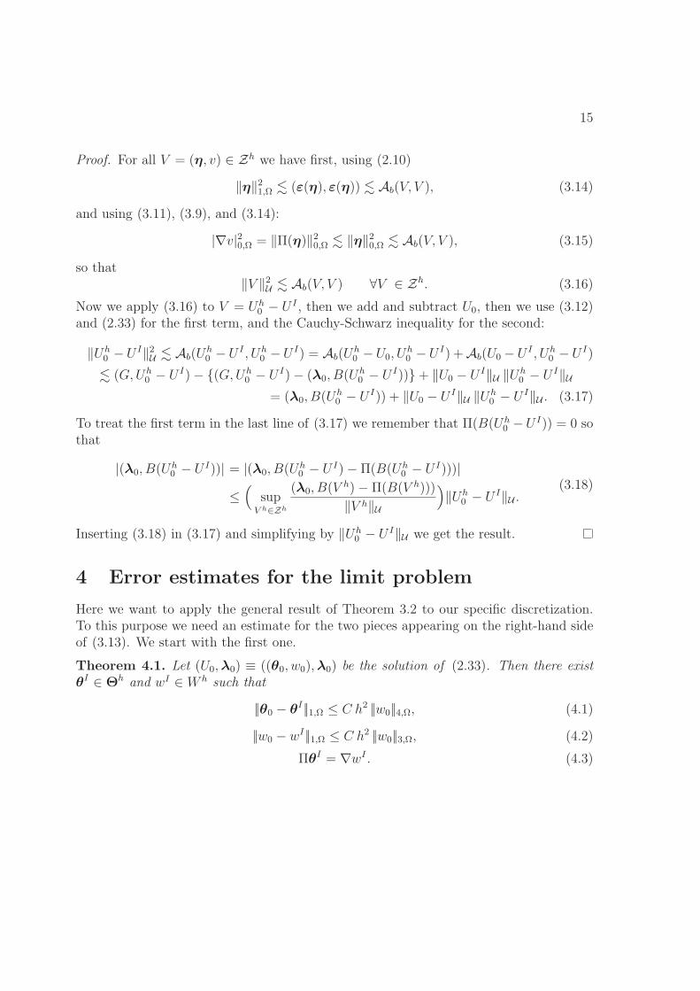
Here we want to apply the general result of Theorem 3.2 to our specific discretization.To this purpose we need an estimate for the two pieces appearing on the right-hand sideof (3.13). We start with the first one.
Theorem 4.1. Let (U0,λ0) ≡ ((θ0, w0),λ0) be the solution of (2.33). Then there existθI ∈ Θh and wI ∈ W h such that
||θ0 − θI ||1,Ω ≤ C h2 ||w0||4,Ω, (4.1)
||w0 − wI ||1,Ω ≤ C h2 ||w0||3,Ω, (4.2)
ΠθI = ∇wI . (4.3)

16
Proof. We follow techniques similar to those used in [27]. Define first w as the Bogner-Fox-Schmit approximation of w0 defined locally by:
w ∈ C1(Ω) : w|K ∈ Q3(K) ∀K,
w = w0, wx = (w0)x, wy = (w0)y, wxy = (w0)xy at the vertices of each K,
(4.4)
and recall that, on each K,
|w − w0|s,K ≤ C hr−s|w0|r,K , 0 ≤ s ≤ r ≤ 4. (4.5)
Next, let wI ∈ Wh be the classical 9-nodes continuous interpolant of w, defined locally by
wI ∈ Q2(K) ∀K,
wI = w at the four vertices of each element K,
wI = w at the midpoints of each edge e of K, ∀K,
wI = w at the barycenter of each element K,
(4.6)
for which the following estimate holds
|w − wI |s,K ≤ C hr−s|w|r,K ≤ C hr−s|w0|r,K , 0 ≤ s ≤ r ≤ 3 (4.7)
for all K. Setting wI = wI , from (4.5) and (4.7) we have then in particular
‖w0 − wI‖1,Ω ≤ ‖w0 − w‖1,Ω + ‖w − wI‖1,Ω ≤ C h2|w0|3,Ω. (4.8)
We notice that an alternative, equivalent definition of (4.6) is:
wI ∈ Q2(K) ∀K,
wI = w at the four vertices of each element K,∫e
(w − wI)ds = 0 on each edge e of K, ∀K,∫K
(w − wI)dxdy = 0, ∀K.
(4.9)
Indeed, by Simpson integration formula on each edge, exact for polynomials of degree≤ 3 we deduce ∫
e
(w − wI)ds = 0 on each edge e of K.

17
By applying tensor-product Simpson rule we also deduce∫K
(w − wI)dxdy = 0 ∀K.
We define now θI ∈ Θh as the continuous interpolant of ∇w defined as in (4.6), that is,
θI1 = wx, θI2 = wy at the 9 nodes. (4.10)
From (4.5) and (4.7) we deduce
||θ0 − θI ||1,Ω = ||∇(w0 − w) +∇w − θI ||1,Ω ≤ C h2|w0|4,Ω. (4.11)
In order to prove (4.3), let K ≡ (xi, xi+1)× (yj, yj+1) be an element of Th, let e(x, yj) :=w(x, yj) − wI(x, yj), and let p1(x) be any polynomial of degree ≤ 1. Using (4.6) and(4.9) we easily have that e(x, yj) vanishes at the endpoints and it has zero mean value on(xi, xi+1). Hence, integrating by parts,
∫ xi+1
xi
ex(x, yj)p1(x) dx = −∫ xi+1
xi
e(x, yj)p1,x(x) dx+ e(x, yj)p1(x)∣∣∣xi+1
xi
= 0.
It follows then that ex(x, yj) is a Legendre polynomial of degree 2. As such, it vanishesat the 2 Gauss points x�1
i , x�2i of (xi, xi+1). Hence,
wx(x�1i , yj) = wI
x(x�1i , yj), wx(x
�2i , yj) = wI
x(x�2i , yj). (4.12)
We further remark that on the horizontal line y = yj we have that θI1 and wx are bothpolynomial of degree 2. Using (4.10) we see that they coincide at three points, and hencethey coincide on the whole line. Hence we might rewrite (4.12) as
θI1(x�1i , yj) = wI
x(x�1i , yj), θI1(x
�2i , yj) = wI
x(x�2i , yj). (4.13)
With the same argument we deduce that θI1(x, y) − wIx(x, y) also vanishes at the Gauss
points of y = yj+1 and y = ymj . For θI2 the same argument applies on the vertical edges,using ey(xi, y) = wy(xi, y)− wI
y(xi, y), so that
ΠθI = ∇wI , (4.14)
and the proof is concluded.
18
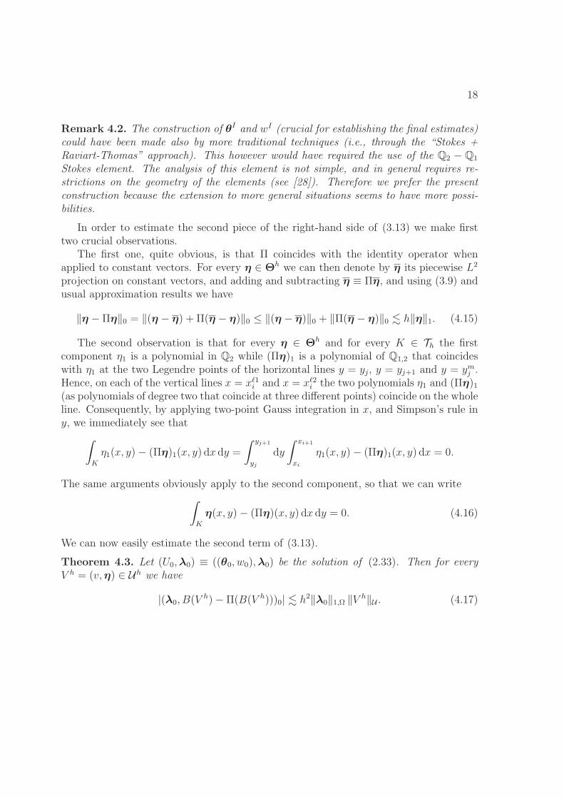
Remark 4.2. The construction of θI and wI (crucial for establishing the final estimates)could have been made also by more traditional techniques (i.e., through the “Stokes +Raviart-Thomas” approach). This however would have required the use of the Q2 − Q1
Stokes element. The analysis of this element is not simple, and in general requires re-strictions on the geometry of the elements (see [28]). Therefore we prefer the presentconstruction because the extension to more general situations seems to have more possi-bilities.
In order to estimate the second piece of the right-hand side of (3.13) we make firsttwo crucial observations.
The first one, quite obvious, is that Π coincides with the identity operator whenapplied to constant vectors. For every η ∈ Θh we can then denote by η its piecewise L2
projection on constant vectors, and adding and subtracting η ≡ Πη, and using (3.9) andusual approximation results we have
‖η − Πη‖0 = ‖(η − η) + Π(η − η)‖0 ≤ ‖(η − η)‖0 + ‖Π(η − η)‖0 � h‖η‖1. (4.15)
The second observation is that for every η ∈ Θh and for every K ∈ Th the firstcomponent η1 is a polynomial in Q2 while (Πη)1 is a polynomial of Q1,2 that coincideswith η1 at the two Legendre points of the horizontal lines y = yj, y = yj+1 and y = ymj .Hence, on each of the vertical lines x = x�1
i and x = x�2i the two polynomials η1 and (Πη)1
(as polynomials of degree two that coincide at three different points) coincide on the wholeline. Consequently, by applying two-point Gauss integration in x, and Simpson’s rule iny, we immediately see that∫
K
η1(x, y)− (Πη)1(x, y) dx dy =
∫ yj+1
yj
dy
∫ xi+1
xi
η1(x, y)− (Πη)1(x, y) dx = 0.
The same arguments obviously apply to the second component, so that we can write∫K
η(x, y)− (Πη)(x, y) dx dy = 0. (4.16)
We can now easily estimate the second term of (3.13).
Theorem 4.3. Let (U0,λ0) ≡ ((θ0, w0),λ0) be the solution of (2.33). Then for everyV h = (v,η) ∈ Uh we have
|(λ0, B(V h)− Π(B(V h)))0| � h2‖λ0‖1,Ω ‖V h‖U . (4.17)

19
Proof. We begin by recalling that from (2.24) we have B(V h) = ∇v − η, and from (3.8)we have Π(∇v) = ∇v, so that
B(V h)− Π(B(V h)) = −η +Π(η). (4.18)
Hence, introducing λ0 as the piecewise constant mean value of λ0, using (4.16)andCauchy-Schwarz, and then usual approximation results and (4.15) we have∣∣∣ ∫
Ω
λ0(η − Πη) dx dy∣∣∣ =∣∣∣ ∫
Ω
(λ0 − λ0)(η − Πη) dx dy∣∣∣ ≤ ‖λ0 − λ0‖0,Ω ‖η − Πη‖0,Ω
� h2‖λ0‖1,Ω ‖η‖1,Ω. (4.19)
Collecting the result of Theorem 3.2 together with the results of Theorems 4.1 and4.3 we now have the final result.
Theorem 4.4. Let (U0,λ0) ≡ ((w0,θ0),λ0) be the solution of (2.33), and let Uh0 be the
solution of (3.12). Then we have
‖U0 − Uh0 ‖U � h2 (‖w0‖3,Ω + ‖λ0‖1,Ω). (4.20)
Therefore the element should behave optimally in the numerical plate solution con-sidered in Fig. 1.1 and this is indeed the case as shown in Fig. 1.2 .
5 Concluding remarks
Our objective in this paper was to give a mathematical analysis of the MITC9 shellelement when used in plate bending solutions. Shell elements are used in general tomodel plate structures in engineering and the sciences; hence the analysis pursued hereinis of considerable interest. While we considered a simplified setting, namely a clampedplate problem solved using uniform meshes and the limit problem with plate thicknessequal to zero, the analysis is valuable because it gives insight into the behavior of theelement.
The mathematical convergence analysis given in the paper shows that in this simplesetting the element behaves optimally for displacements and rotations and hence doesnot lock. Some numerical results given in the paper also illustrate that it is reasonableto consider the case of vanishing plate thickness for the mathematical analysis.

20
Considering future work, since we used in all our analyses uniform meshes, it wouldbe of value to also study the performance of the element in non-uniform decompositions,as well as the case of positive thickness. Furthermore, a more general mathematicalconvergence analysis of the MITC9 shell element when used for the solution of actualshell problems, that is, involving curved thin structures, would be very valuable.
References
[1] Bathe KJ. Finite element procedures. New York: Prentice Hall; 1996.
[2] Zienkiewicz OC. and Taylor RL, The finite element method. Butterworth-Heinemann; 2005.
[3] Brezzi F, Bathe KJ, and Fortin M, Mixed-interpolated elements for Reissner/Mindlinplates, Int. J. Num. Methods in Engineering, 28, 1787-1801, 1989.
[4] Brezzi F and Fortin M. Mixed and hybrid finite element methods. Springer; 1991.
[5] Bathe KJ, Brezzi F, and Cho SW. The MITC7 and MITC9 plate bending elements.Comput Struct 1989;32:797-814.
[6] Bathe KJ, Bucalem M, and BrezziF. Displacement and stress convergence of theMITC plate bending elements, J. Eng. Computations, 7, no. 4, 291-302, 1990.
[7] Chapelle D and Bathe KJ. Fundamental considerations for the finite element analysisof shell structures. Comput Struct 1998;66:19-36,711-2.
[8] Chapelle D and Bathe KJ. The finite element analysis of shells - Fundamentals.Springer; 2003, 2nd edition in press.
[9] Lee PS and Bathe KJ. On the asymptotic behavior of shell structures and the eval-uation in finite element solutions. Comput Struct 2002;80:235-55.
[10] Lee PS and Bathe KJ. Insight into finite element shell discretizations by use of thebasic shell mathematical model. Comput Struct 2005;83:69-90.
[11] Blouza A, Brezzi F, and Lovadina C. On the classification of linearly elastic shellsC.R.A.S., Serie I 1991;328:831-836
[12] Baiocchi C and Lovadina C. A shell classification by interpolation. Mat. Mod. Meth-ods Appl. Sci. 2002;12:1359-1380
21
[13] Beirao da Veiga L. Asymptotic energy behavior of two classical intermediate bench-mark shell problems. Mat. Mod. Methods Appl. Sci. 2003;13:1279-1302
[14] Beirao da Veiga L and Chinosi C. Numerical evaluation of the asymptotic energybehavior of intermediate shells with application to two classical benchmark tests.Comput Struct 2004;82:525-34.
[15] Beirao da Veiga L. Asymptotic study of the solution for pinched cylindrical shellsComp. Meth. Appl. Mech. Engrg. 2005;194: 1113-39
[16] Hiller JF and Bathe KJ. Measuring convergence of mixed finite element discretiza-tions: An application to shell structures. Comput Struct 2003;81:639-54.
[17] Bathe KJ and Lee PS. Measuring the convergence behavior of shell analysis schemes,Comput Struct, in press.
[18] Kardestuncer H.(ed), Finite element handbook, MacGraw-Hill, 1987.
[19] Bucalem M and Bathe KJ. The mechanics of solids and structures - hierarchicalmodeling and the finite element solution, Springer, to appear.
[20] Bathe KJ. The finite element method, in Encyclopedia of Computer Science andEngineering, B. Wah (ed.), J. Wiley and Sons; 2009, 1253-64.
[21] Lee PS, Bathe KJ. The quadratic MITC plate and MITC shell elements in platebending. Advances in Engineering Software 2010;41:712-28.
[22] Bathe KJ, Lee PS, Hiller JF. Towards improving the MITC9 shell element. ComputStruct 2003;81:477-89.
[23] Bucalem M and Bathe KJ. Higher-order MITC general shell elements, Int. J. forNumerical Methods in Engineering, 36, 3729-3754, 1993.
[24] Iosilevich A, Bathe KJ, and Brezzi F. On evaluating the inf-sup condition for platebending elements, Int. Journal for Numerical Methods in Engineering, 40, 3639-3663,1997.
[25] Chapelle D and Bathe KJ. On the ellipticity condition for model-parameter depen-dent mixed formulations, Comput Struct 2010; 88:581-87.
[26] Brezzi F, Fortin M, Stenberg R Error Analysis of mixed-interpolated elements forReissner-Mindlin plates, Math. Mod. and Meth. in Appl. Sci. M3 AS, 1, 125-151,1991.

22
[27] Brezzi F, Evans JA, Hughes TJR, and Marini LD. New Quadrilateral Plate ElementsBased on Twist-Kirchhoff Theory, in preparation.
[28] Stenberg R. Blandade finita elementmetoder for tva problem inom stromn-ingsmekaniken och hallfathetslaran, Licentiatarbete, Department of TechnicalPhysics and Mathematics, Helsinki University of Technology, 1981.


![tsukuru技報№2010Fig. 4 Strain distribution in longitudinal direction [Roll shell] SS400 steel late Bending, Welding Machining before welding Setting water-blocki late Setting jigs](https://static.fdocuments.us/doc/165x107/6114a7aa31f83e783a4846ed/tsukurua2010-fig-4-strain-distribution-in-longitudinal-direction-roll.jpg)


![Problem Solving of the Lightened Concrete Gravity ... · bending theory in cylindrical shell thanks with retaining walls [19], review of development of the theory of shell analysis](https://static.fdocuments.us/doc/165x107/5e88fc673f1d276f732e9e71/problem-solving-of-the-lightened-concrete-gravity-bending-theory-in-cylindrical.jpg)