THEMIS EOMP ReviewEFINov 19, 2009 THEMIS Electric Field Instrument (EFI) Dr. John Bonnell Space...
31
THEMIS EOMP Review EFI Nov 19, 2009 THEMIS Electric Field Instrument (EFI) Dr. John Bonnell Space Sciences Laboratory UC Berkeley
-
Upload
marion-daniel -
Category
Documents
-
view
229 -
download
0
Transcript of THEMIS EOMP ReviewEFINov 19, 2009 THEMIS Electric Field Instrument (EFI) Dr. John Bonnell Space...

THEMIS EOMP Review EFI Nov 19, 2009
THEMIS
Electric Field Instrument (EFI) Dr. John Bonnell
Space Sciences Laboratory
UC Berkeley

THEMIS EOMP Review EFI Nov 19, 2009
Performance vs. Specifications
• EFI has met or exceeded on-orbit performance requirements and specifications (all requirements and specs included in appendix):• 30 sensors still functional and in spec after 33 months on-orbit,
including long- and short-duration eclipses (lifetime; thermal).• No obvious signs of degradation in performance:
• no dramatic increases in offsets or shifts in gain.• no increases in power consumption.• no loss of current- or voltage-bias control.• no problems with commanding or configuration control.
• 2D DC and 3D AC E-field estimates from EFI have been made in support of all three mission objectives:
• Substorm Onset (E-fields in tail to 1 mV/m)• Radiation Belt Acceleration Processes (AC measurements to 4-8
kHz.• Dayside Magnetopause Observations (E fields at M’Pause to few
mV/m).• On-orbit calibration and offset estimation and removal allow for
accuracies better than 1 mV/m, if cold plasma wake effects are not present.

THEMIS EOMP Review EFI Nov 19, 2009
Assessment of Data Products (1)
• L1 EFI data products are sufficient to meet Level-1 Science Requirements (EFI-1 to -4):
REQUIREMENT EFI DESIGN
IN.EFI-1. The EFI shall determine the 2D spin plane electric field at the times of onset at 8-10 Re.
Compliance. Via compliance with IN.EFI-5 and -13.Both spin-fit (3-s resolution) and waveform (4-, 128-, 4096/8192-samp/s provided); e.g. Sergeev et al., 2008; Uritsky et al., GRL, 2009).
IN.EFI-2. The EFI shall determine the dawn/dusk electric field at 18-30 Re.
Compliance. Via compliance with IN.EFI-5 and -13.Measures both components well. (e.g. Sergeev et al., 2008).
IN.EFI-3. The EFI shall measure the 3D wave electric field in the frequency range 1-600Hz at the times of onset at 8-10 Re.
Compliance. Via compliance with IN.EFI-6, -8, -9, -10, and –11. (e g. Sergeev et al., 2009).Low-frequency end (<10 Hz) requires significant processing on axial measurements.
IN.EFI-4. The EFI shall measure the waves at frequencies up to the electron cyclotron frequency that may be responsible for electron acceleration in the radiation belt.
Compliance. Via compliance with IN.EFI-6, -8, -9, -10, and –11. (e g. Bortnik et al., 2009; Li et al., 2009)Both waveform and spectral data supplied; wake effects can contaminate results in some cases.

THEMIS EOMP Review EFI Nov 19, 2009
Assessment of Data Products (2)
• L1 EFI data products are sufficient to meet Level-1 Science Requirements (EFI-5 to -10):
REQUIREMENT EFI DESIGN
IN.EFI-5. The EFI shall measure the 2D spin plane DC E-field with a time resolution of 10 seconds.
Compliance. On-board spin-fit of spin plane E-field at 3-s (one-spin) resolution. (e.g. Liu et al, GRL, accepted, 2009).
IN.EFI-6. The EFI shall measure the 3D AC E-field from 1 Hz to 4 kHz.
Compliance. 3-axis E-field measurement sampled at 8 ksamp/s. See AC Error Budget. Verified through Calibration. (e.g. Cully et al., GRL, 2008; Ergun et al., 2009)
IN.EFI-7. The EFI shall measure the Spacecraft Potential with a time resolution better than the spin rate (3 seconds; from ESA to compute moments).
Compliance. On-board spin-avg’d sphere potentials at 3-s (spin-rate) resolution; EFI data rate allocation includes single spheres at ¼-rate of E-field data.
IN.EFI-8. The EFI DFT Spectra Range shall be 16Hz to 4kHz, with df/f~25%.
Compliance. Spectral products from DFB cover 8 Hz to 8 kHz at 5%, 10%, or 20% BW (16, 32, or 64 bins). Verified at DFB Functional Test. (e.g. Bortnik et al., Nature, 2009).
IN.EFI-9. The EFI shall measure DC-coupled signals of amplitude up to 300 mV/m with 16-bit resolution.
Compliance. Analog gain and ADC resolution of DFB set accordingly. Verified at DFB Functional Test. (e.g. Cully et al., GRL, 2008).
IN.EFI-10. The EFI shall measure AC-coupled signals of amplitude up to 50 mV/m with 16-bit resolution.
Compliance. Analog gain and ADC resolution of DFB set accordingly. Verified at DFB Functional Test. (e.g. Andersson et al., PRL, 2009).

THEMIS EOMP Review EFI Nov 19, 2009
Assessment of Data Products (3)
• L1 EFI data products are sufficient to meet Level-1 Science Requirements (EFI-11 to -13):
REQUIREMENT EFI DESIGN
IN.EFI-11. The EFI noise level shall be below 10-4 (mV/m)/Hz1/2.
Compliance. Low-noise preamp chosen (OP-15); good analog design practices throughout preamp, BEB and DFB; CBE in Flight config is few times 10-4 (mV/m)/Hz1/2. (e.g. Cully et al., GRL, 2008).
IN.EFI-12. The EFI HF RMS (Log power) measurement shall cover 100-500 kHz with a minimum time resolution of the spin rate (on-board triggers).
Compliance. Measured end-to-end gain of EFI sensors in the 100-500-kHz band is 0.4; DFB provides HF-RMS at 1/16 to 8 samp/s. Verified at DFB Functional Test and SciCal.Trigger functions written to use HF_RMS signal, and study of use of HF_RMS as indicator of plasma wave activity performed (Cully, private comm., 14 May 2008).
IN.EFI-13. The EFI shall achieve an accuracy better than 10% or 1 mV/m in the SC XY E-field components during times of onset.
Compliance. See DC Error Budget Discussion. (e.g. Sergeev et al, JGR, 2008).

THEMIS EOMP Review EFI Nov 19, 2009
Assessment of Data Products (2)
• L1 EFI data products support investigations beyond L1 science requirements:• Hall E-field measurements at the dayside magnetopause (e.g.
Mozer et al., 2008).• Hall E-field measurements in tail dipolarization events (McFadden,
private comm., 2008-9).• Coordinated E- and B-field measurements in geomagnetic
pulsation studies (spin-fit and waveform) (e.g. Liu et al., 2009).• Double layer and electron hole observations in magnetotail (e.g.
Andersson et al., 2009; Ergun et al., 2009).

THEMIS EOMP Review EFI Nov 19, 2009
Data Maturity (1)• L1 EFI data reprocessed several times in order to remove on-board
data collection anomalies:• Time Tagging, prior to correction in FSW.• Spikes in high-rate (WaveBurst) data (impacts << 0.1% of WB data).
• L1 data is accessible through TDAS package (IDL crib sheets and procs), as well as the Science Data Tool (old-school E-field community).
• Calibration has both fixed (gains, sunward offsets) and time-dependent elements. • Fixed calibration parameters (gains sunward/dawn-dusk offsets) computed using cal
runs in magnetosheath. • Time-dependent element is computed on-the-fly in TDAS and SDT processing, both
for DC (FastSurvey) and AC (Pburst, Wburst) data types.
• Accuracy is at least 1 mV/m for 2D spin plane fields, with few tens of mV/m for the axial estimate (after heavy processing).
• Description and discussion of calibration and error sources in Bonnell et al. (2008), as well as on EFI Instrument web page.

THEMIS EOMP Review EFI Nov 19, 2009
Data Maturity (2)• Preliminary quality flags available, but not formalized:
• detection of wake effect fields through comparison of long- and short-antenna results.
• Limitation of E∙B=0 estimates of Eperp to limited ranges of (Bspin/Baxial).
• L2 EFI data processing in the works, but data still needs significant care in use and interpretation.

THEMIS EOMP Review EFI Nov 19, 2009
EFI Lessons Learned
• Wake effect fields due to flowing cold plasma have significant impact (tens of mV/m) on magnetospheric side of dayside magnetopause, as well as in inner magnetosphere → • longer booms.• SC potential control.• continuous waveform measurements, or spin-fit of both spin plane signals, rather than
just one.
• 7-m tip-to-tip axial antennas are too short for making 1 mV/m 3D DC measurements → • longer booms.• adjustable boom lengths on-orbit.
• Photoelectron fluxes returning to SC and body-mounted particle detectors can be significant and can impact low-energy (few to tens eV) e- measurements → • GUARD surfaces run at positive, rather than negative potentials. • adjust voltage biasing scheme of DBRAID surfaces during sensor eclipse season.

THEMIS EOMP Review EFI Nov 19, 2009
BACKUP SLIDES:• References.• Requirements and Specs.• On-Orbit Operation and Calibration.• Measurement Challenges.
THEMIS EOMP Review EFI Nov 19, 2009
References• Andersson et al., New features of electron phase space holes observed by the
THEMIS mission, PRL, accepted, 30 Apr 2009.• Bonnell et al., The electric field instrument (EFI) for THEMIS, SSR,
doi:10.1007/s11214-008-9469-2.• Bortnik et al., An Observation Linking the Origin of Plasmaspheric Hiss to Discrete
Chorus Emissions, Science 324, 5928, 775 - 778, doi: 10.1126/science.1171273.• Cully et al., THEMIS Observations of Long-lived Regions of Large-Amplitude
Whistler Waves in the Inner Magnetosphere, GRL, doi:10.1029/2008GL033643.• Ergun et al., Observations of Double Layers in Earth’s Plasma Sheet , PRL, 102,
155002.• Li et al., Global Distribution of Whistler-mode Chorus Waves Observed on the
THEMIS Spacecraft, GRL, 2009.• Liu et al, Solar wind influence on Pc4 and Pc5 ULF wave activity in the inner
magnetosphere, GRL, accepted, 2009.• Mozer et al., THEMIS observations of modified Hall fields in asymmetric magnetic
field reconnection, GRL, doi:10.1029/2007GL033033.• Segeev et al., THEMIS observations in the near-tail portion of the inner and outer
plasma sheet flux tubes at substorm onset, JGR, doi:10.1029/2008JA013527. Sergeev et al., Kinetic structure of the sharp injection/dipolarization frontin the flow-braking region, GRL, doi:10.1029/2009GL040658.

THEMIS EOMP Review EFI Nov 19, 2009
REQUIREMENT EFI DESIGN
IN-1. The Instrument Payload shall be designed for at least a two-year lifetime.
Compliance. Lifetime has been considered in all aspects of EFI and DFB design (parts, performance degradation, etc.).
IN-2. The Instrument Payload shall be designed for a total dose environment of 33 krad/year (66 krad for 2 year mission, 5mm of Al, RDM 2)
Compliance. Common Parts Buy for Instrument Payload. All parts screened for total dose. Radiation testing planned if TID is unknown.
IN-3. The Instrument Payload shall be Single Event Effect (SEE) tolerant and immune to destructive latch-up.
Compliance. Common Parts Buy for Instrument Payload. All parts screened for total dose. Radiation testing planned if LET is unknown.
Lifetime, Radiation

THEMIS EOMP Review EFI Nov 19, 2009
REQUIREMENT EFI DESIGN
IN-7. No component of the Instrument Payload shall exceed the allocated mass budget in THM-SYS-008 THEMIS System Mass Budget.xls
Compliance. SPB: 1.816 kg Allocated; 1.80 kg (F1 measured). AXB: 4.185 kg Allocated; 4.103 kg (F1 measured).BEB: 0.464 kg Allocated; 0.462 kg (F1 measured).DFB: 0.398 kg Allocated; 0.400 kg (F1 measured)Harness: 0.905 kg Allocated; 0.905 kg (F1 measured)
IN-9. No component of the Instrument Payload shall exceed the power allocated in THM-SYS-009 THEMIS System Power Budget.xls
Compliance. Preamps: 0.09 W Allocated; 0.05 W (FLT nominal). note: Preamp power included in BEB allocation.BEB: 1.76 W Allocated; 1.1 W CBE (ETU).DFB: 0.853 W/0.890 W/1.470 W max.
IN-13. The Instrument Payload shall survive the temperature ranges provided in the ICDs.
Compliance. SPB and AXB received 4 cycles at Instrument level, with Hot and Cold deploy tests. Preamp Thermal Qual (ETU) and Acceptance (FLT) tests completed prior to Instrument integration.
IN-14. The Instrument Payload shall perform as designed within the temperature ranges provided in the ICDs
Compliance. See IN-13.
Mass, Power, Thermal

THEMIS EOMP Review EFI Nov 19, 2009
REQUIREMENT EFI DESIGN
IN-16 The Instrument Payload shall comply with the Magnetics Cleanliness standard described in the THEMIS Magnetics Control Plan
Compliance. THM-SYS-002 Magnetics Control Plan. Budget for EFI Magnets (Boom Motors) is <0.75nT @ 2 meters; CBE by measurement is 0.25 nT @ 2 meters.
IN-17 The Instrument Payload shall comply with the THEMIS Electrostatic Cleanliness Plan
Compliance. Design, fabrication, and testing in accordance with THM-SYS-003 Electrostatic Cleanliness Plan. Verified at Instrument level in CPT/LPT testing.
IN-18 The Instrument Payload shall comply with the THEMIS Contamination Control Plan
Compliance. Design and fabrication in accordance with THM-SYS-004 Contamination Control Plan.
IN-19. All Instruments shall comply with all electrical specifications
Compliance. Design in accordance with THM-IDPU-001 Backplane Specification (BEB, DFB). Verified by board-level and IDPU-integration level testing.
IN-20. The Instrument Payload shall be compatible per IDPU-Instrument ICDs
Compliance. THM-SYS-103 DFB-to-IDPU ICD signed off. THM-SYS-104 BEB-to-IDPU ICD signed off. ICD compliance confirmed by direct measurement during II&T.
IN-21. The Instrument Payload shall be compatible per the IDPU-Probe Bus ICD.
Compliance. Both THM-SYS-108 Probe-to-EFI Radial Booms ICD, and THM-SYS-109 Probe-to-EFI Axial Booms ICD are signed off. ICD compliance confirmed by direct measurement during II&T.
Cleanliness; Elect., Mech. ICD

THEMIS EOMP Review EFI Nov 19, 2009
REQUIREMENT EFI DESIGN
IN-23 The Instrument Payload shall verify performance requirements are met per the THEMIS Verification Plan and Environmental Test Spec.
Compliance. Instrument Suite-level environmental testing to be completed as per THM-SYS-005 Verification Plan and Environmental Test Specification.
IN-24 The Instrument Payload shall survive and function prior, during and after exposure to the environments described in the THEMIS Verification Plan and Environmental Test Specification.
Compliance. Instrument Suite-level environmental testing to be completed as per THM-SYS-005 Verification Plan and Environmental Test Specification. Suite-level CPT developed during II&T of F1.
Environmental Testing

THEMIS EOMP Review EFI Nov 19, 2009
REQUIREMENT EFI DESIGN
IN.EFI-1. The EFI shall determine the 2D spin plane electric field at the times of onset at 8-10 Re.
Compliance. Via compliance with IN.EFI-5 and -13.
IN.EFI-2. The EFI shall determine the dawn/dusk electric field at 18-30 Re.
Compliance. Via compliance with IN.EFI-5 and -13.
IN.EFI-3. The EFI shall measure the 3D wave electric field in the frequency range 1-600Hz at the times of onset at 8-10 Re.
Compliance. Via compliance with IN.EFI-6, -8, -9, -10, and –11.
IN.EFI-4. The EFI shall measure the waves at frequencies up to the electron cyclotron frequency that may be responsible for electron acceleration in the radiation belt.
Compliance. Via compliance with IN.EFI-6, -8, -9, -10, and –11.
Science Requirements

THEMIS EOMP Review EFI Nov 19, 2009
REQUIREMENT EFI DESIGN
IN.EFI-5. The EFI shall measure the 2D spin plane DC E-field with a time resolution of 10 seconds.
Compliance. On-board spin-fit of spin plane E-field at 3-s (one-spin) resolution.
IN.EFI-6. The EFI shall measure the 3D AC E-field from 1 Hz to 4 kHz.
Compliance. 3-axis E-field measurement sampled at 8 ksamp/s. See AC Error Budget. Verified through Calibration.
IN.EFI-7. The EFI shall measure the Spacecraft Potential with a time resolution better than the spin rate (3 seconds; from ESA to compute moments).
Compliance. On-board spin-avg’d sphere potentials at 3-s (spin-rate) resolution; EFI data rate allocation includes single spheres at ¼-rate of E-field data.
IN.EFI-8. The EFI DFT Spectra Range shall be 16Hz to 4kHz, with df/f~25%.
Compliance. Spectral products from DFB cover 8 Hz to 8 kHz at 5%, 10%, or 20% BW (16, 32, or 64 bins). Verified at DFB Functional Test.
IN.EFI-9. The EFI shall measure DC-coupled signals of amplitude up to 300 mV/m with 16-bit resolution.
Compliance. Analog gain and ADC resolution of DFB set accordingly. Verified at DFB Functional Test.
IN.EFI-10. The EFI shall measure AC-coupled signals of amplitude up to 50 mV/m with 16-bit resolution.
Compliance. Analog gain and ADC resolution of DFB set accordingly. Verified at DFB Functional Test.
Performance Requirements

THEMIS EOMP Review EFI Nov 19, 2009
REQUIREMENT EFI DESIGN
IN.EFI-11. The EFI noise level shall be below 10-4 (mV/m)/Hz1/2.
Compliance. Low-noise preamp chosen (OP-15); good analog design practices throughout preamp, BEB and DFB; CBE in Flight config is few times 10-4 (mV/m)/Hz1/2.
IN.EFI-12. The EFI HF RMS (Log power) measurement shall cover 100-500 kHz with a minimum time resolution of the spin rate (on-board triggers).
Compliance. Measured end-to-end gain of EFI sensors in the 100-500-kHz band is 0.4; DFB provides HF-RMS at 1/16 to 8 samp/s. Verified at DFB Functional Test and SciCal.
IN.EFI-13. The EFI shall achieve an accuracy better than 10% or 1 mV/m in the SC XY E-field components during times of onset.
Compliance. See DC Error Budget Discussion.
Performance Requirements

THEMIS EOMP Review EFI Nov 19, 2009
REQUIREMENT EFI DESIGN
DFB FUNCTIONAL REQUIREMENTS
IN.DPU-36. The IDPU DFB shall provide an FFT solution for determining the parallel and perpendicular components of E and B in both fast survey and burst modes and produce spectra for each quantity separately.
Compliance. DFB design includes FPGA-based projection (E dot B, E cross B) and FFT solutions. Verified through DFB Functional Test, and II&T testing.
IN.DPU-37. The IDPU DFB shall integrate FGM digital data and EFI data to produce E·B.
Compliance. DFB design includes FPGA-based projection ( E dot B, E cross B) solutions. Verified through DFB Functional Test, and II&T testing.
EFI Board Requirements

THEMIS EOMP Review EFI Nov 19, 2009
REQUIREMENT EFI DESIGN
BEB FUNCTIONAL REQUIREMENTS
IN.DPU-38. The IDPU BEB shall provide sensor biasing circuitry, stub and guard voltage control for the EFI.
Compliance. The BEB design provides 3 independent bias channels per sensor (BIAS,GUARD,USHER) and one shared bias channel for the SPB sensors (BRAID). Boom deployment is provided through the IDPU/PCB and DCB. Verified during BEB Functional Test.
IN.DPU-39. The IDPU BEB shall distribute a floating ground power supply to the EFI sensors.
Compliance. The BEB design provides 6 independent floating grounds to the LVPS, and distributes the derived +/-10-V analog supplies to the six EFI sensors. Verified during BEB Functional Test.
IN.DPU-40. The IDPU BEB shall generate six independent BIAS, GUARD and USHER voltages with an accuracy of 0.1% for distribution to the EFI sensors.
Compliance. The BEB and EFI Preamp designs include matched gain-setting components, along with >12-bit DAC, allowing accuracy of better than 0.1%; Accuracy has been verified through BEB Functional Test and SciCal.
EFI Board Requirements

THEMIS EOMP Review EFI Nov 19, 2009
REQUIREMENT EFI DESIGN
IN.BOOM-5a. Deployed EFI Axials shall be repeatable and stable to Dq = 1 degree and DL/L = 1%.
Compliance. Adequate stiffness and angular alignment of AXB stacers and deploy system included in design; verified by Vertical Deploy Test (0.5 deg. And 1% typ.).
IN.BOOM-5b. Length of deployed EFI Radials shall be repeatable and stable to Dq = 1 degree and DL/L = 1%.
Compliance. Proper SPB cable design (limpness, CTE) along with std. Cable winding procedures included in design; verified by Vertical Deploy Test.
IN.BOOM-6. EFI Axial Booms shall be designed to be deployed between 2 and 25 RPM about the Probe's positive Z axis.
Compliance. Adequate stiffness and angular alignment of AXB stacers included in design; verified by Vertical Deploy Test.
IN.BOOM-7. EFI Radial Booms shall be designed to be deployed between 2 and 25 RPM.
Compliance. Adequate strength margins on cable included in design; verified by Pull Test (50-lb. Proof load with electrical continuity check before, during and after loading).
IN.BOOM-8. EFI Axial Booms deployed stiffness shall be greater than 0.75 Hz (1st mode).
Compliance. Part of AXB stacer spec; verified by Stiffness Test; 1st mode frequencies between 1.5 and 2.0 Hz.
IN.BOOM-12. All deployed booms shall include TBD inhibits to prevent inadvertent release.
Compliance. Test/Enable plugs included in design. Red tag AXB tube (AXB) covers, and Science-only Enable plugs.
EFI Boom Requirements

THEMIS EOMP Review EFI Nov 19, 2009
ON-ORBIT OPERATION AND CALIBRATION

THEMIS EOMP Review EFI Nov 19, 2009
On-Orbit Current and Voltage Bias Sweeps“Sensor Diagnostic Test (SDT)”
THEMIS EOMP Review EFI Nov 19, 2009
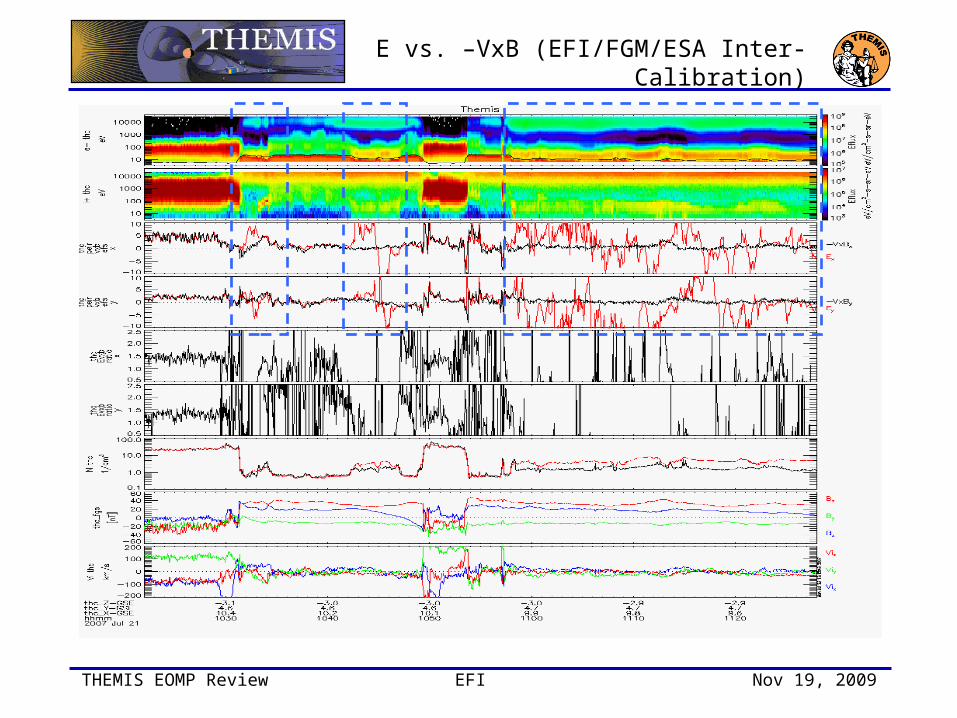
E vs. –VxB (EFI/FGM/ESA Inter-Calibration)

THEMIS EOMP Review EFI Nov 19, 2009
E vs. –VxB (EFI/FGM/ESA Inter-Calibration)

THEMIS EOMP Review EFI Nov 19, 2009
E vs. –VxB (EFI/FGM/ESA Inter-Calibration)

THEMIS EOMP Review EFI Nov 19, 2009
Vsc vs. Ambient Density
• Typical two-slope correlation between Vsc and ambient ion density estimate (iESA).

THEMIS EOMP Review EFI Nov 19, 2009
MEASUREMENT CHALLENGES

THEMIS EOMP Review EFI Nov 19, 2009
ES Cold Plasma Wake
PIC simulation by Engwall & Eriksson (CLUSTER booms)
• Waveforms non-sinusoidal and significant amplitude (tens of mV/m).
• Shorter boom pair (E34) has LARGER signal than long boom pair (E12).
• Occurrance consistent with ESA cold plasma observations, when available:
– ne>ni
– cold (few eV) flowing ions present in iESA spectrum
• Distortion reminiscent of cold plasma wake effect on Cluster [eg. Engwall et al., 2006].
• Rate of occurrence on THEMIS is high; initial estimates of 60-80% of duskside passes.
• Significant for MMS, RBSP E-field measurements.

THEMIS EOMP Review EFI Nov 19, 2009
Short Booms: Axial E vs. Vsc
• Significant correlation between v56 (axial E-field) and Vsc over a broad range of spacecraft potentials (ambient densities) – ≈ 4 ((mV/m)/V)
• Correlation is not strictly linear, and breakpoints probably represent changes in photocloud structure with SC potential.
• Partly explained by the shift in the electrostatic center caused by the mag booms (≈ 6 cm shift!).

THEMIS EOMP Review EFI Nov 19, 2009
What’s Calibration Error and What’s E||?