The World Association for Waterborne Transport …pianc-jp.org/news/images/On Course 144...
54
ON COURSE PIANC E-Magazine 144 2011 NOVEMBER NOVEMBRE Failure of Gansbaai Leeward Breakwater: Fines Washout from Breakwater Core Some Thoughts on the Economics of Dry Docks Stability of Crown Walls of Cube and Cubipod Armoured Mound Breakwaters News from the Navigation Community The World Association for Waterborne Transport Infrastructure Association Mondiale pour les infrastructures de Transport Maritimes et Fluviales
Transcript of The World Association for Waterborne Transport …pianc-jp.org/news/images/On Course 144...
PIANC E-Magazine n° 144, November/novembre 2011
ON COURSEPIANC E-Magazine144 2011NOVEMBER
NOVEMBRE
Failure of Gansbaai Leeward Breakwater: Fines Washout from
Breakwater Core
Some Thoughts on the Economics of Dry Docks
Stability of Crown Walls of Cube and Cubipod Armoured Mound
Breakwaters
News from the Navigation Community The World Association for Waterborne Transport Infrastructure
Association Mondiale pour les infrastructures de Transport Maritimes et Fluviales
PIANC E-Magazine n° 144, November/novembre 2011
PIANC’S PLATINUM PARTNERS
PIANC E-Magazine n° 144, November/novembre 2011
PIANC
Responsible Editor / Editeur responsable :
Mr Louis VAN SCHELBoulevard du Roi Albert II 20, B 3
B-1000 Bruxelles
ISBN: 978-2-87223-170-6 EAN: 9782872231706
All copyrights reserved © Tous droits de reproduction réservés
ON COURSEPIANC E-Magazine
‘ Setting the Course’‘ Garder le cap’
144 2011NOVEMBERNOVEMBRE
PIANC E-Magazine n° 144, November/novembre 2011
PIANC E-Magazine n° 144, November/novembre 2011
TABLE OF CONTENTS Message of the President
Mike Chemaly, Failure of Gansbaai Leeward Break-water: Fines Washout from Breakwater Core
Keith Mackie, Some Thoughts on the Economics of Dry Docks
Jorge Molines, Stability of Crown Walls of Cube and Cubipod Armoured Mound Breakwaters
News from the navigation community
TABLE DES MATIERES
Message du Président
Mike Chemaly, Rupture de la digue de Gansbaai: entraînement des fines du noyau de la digue
Keith Mackie, Considérations sur l’économie des installations de radoub
Jorge Molines, Stabilité des murs de couronnement sur des digues à talus
en Cubipod et blocs cubiques
Des nouvelles du monde de la navigation
6
11
23
29
45
5
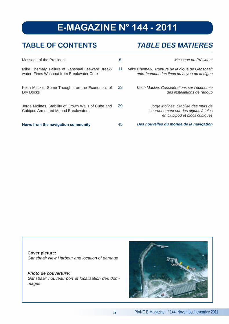
Cover picture: Gansbaai: New Harbour and location of damage
Photo de couverture: Gansbaai: nouveau port et localisation des dom-mages
E-MAGAZINE N° 144 - 2011
PIANC E-Magazine n° 144, November/novembre 2011 6
MESSAGE OF ThE PRESIDENT
NordPIANC
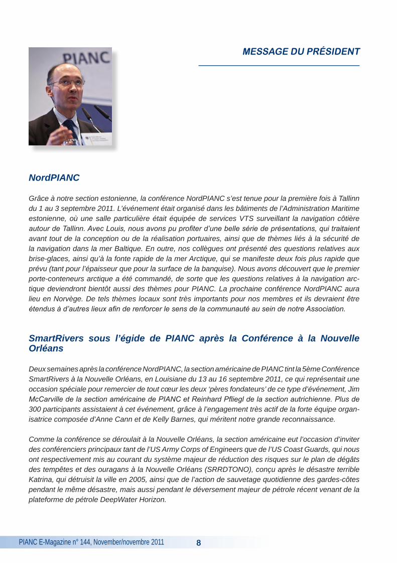
Thanks to our Estonian section, for the first time the NordPIANC Conference was held in Tallinn on Septem-ber 1-3, 2011. The event took place in the buildings of the Estonian Maritime Administration, where a dedi-cated room allows for VTS services along the coast surrounding Tallinn. Together with Louis, we enjoyed a very nice set of presentations mainly about port layout or buildings and navigation safety issues in the Baltic Sea. Our colleagues also presented the ice-breaking issues and the fast melting of the Arctic Sea which oc-curs twice quicker than expected (both in ice sheet thickness and ice surface). We discovered that the first Arctic designed container carrier had been ordered so that Arctic navigation issues will become a matter for PIANC soon. The next NordPIANC Conference will take place in Norway. Such local issues are very impor-tant for our members and should be extended to other places in order to strengthen the sense of community within our Association.
SmartRivers under the PIANC umbrella after the New Orleans Conference
Two weeks after the NordPIANC meeting, the US Section of PIANC held the 5th SmartRivers Conference in New Orleans, Louisiana on September 13-16, 2011, which was a special occasion to thank very warmly both ‘fathers’ of this type of event, Jim McCarville from the US section of PIANC and Reinhard Pfliegl from the Austrian Section. This event was attended by more than 300 participants due to the very active involve-ment of the strong organising team, composed by Anne Cann and Kelly Barnes, who deserve our strong gratitude.
Due to the special location in New Orleans, the US Section was able to invite keynote speakers from both the US Army Corps of Engineers and the US Coast Guards, which respectively taught us about the major Greater New Orleans Hurricane and Storm Damage Risk Reduction System (GNOHSDRRS), built after the terrible Katrina disaster which devastated the city in 2005, as well as about the daily rescue Coast Guards action during the same disaster but also during the recent major oil spill from the DeepWater Horizon petro-leum Platform.
The so-called GNOHSDRRS project costs more than $ 14.6 billion and is by far the largest project launched by the US Army Corps of Engineers since the Hoover Dam, with levees, floodwalls and barriers which can avoid the Gulf surge through navigation channels. It deserves a full publication or at least a full PIANC ‘On Course’, since there is always much to learn from such huge works, even for smaller works!

PIANC E-Magazine n° 144, November/novembre 20117
In my opinion, three major hazard events question the scope which PIANC considers to deal either with natural of with technology-related hazards: Katrina of course and for such large hurricanes, which can af-fect many ports, coasts and waterways, tsunami issues with the recent Fukushima disaster in Japan and to a lesser extent in terms of consequences with the Eyjafjallajoküll volcano eruption which disturbed not only the whole air traffic on a world scale but also port works, as our Icelandic colleague Sigurdur Gretarsson de-scribed in Tallinn. How can we progress in the way we consider the safety design issues from such events? Some of our publications dealt with these issues in the past, but we need to undertake a more horizontal approach on this topic.
At the end of this very fruitful Conference, we were able to sign an agreement between PIANC Headquarters and the organising leaders, Otto Schwetz and Reinhard Pfiegl, which brings a full integration of SmartRivers within PIANC. Like COPEDEC, SmartRivers becomes a full part of PIANC. The next SmartRivers Confer-ence will be hosted both by Belgium (Liège) and The Netherlands (Maastricht) in 2013, which is a very nice combination.
Future Events
Among our upcoming events there will be our next ExCom, Council and Secretaries meetings in February 2012, as well as the PIANC-COPEDEC Conference in Chennai, India. With the World Water Forum in Mar-seille in March we expect dedicated presentations about sustainable inland navigation issues.
I wish all of you a pleasant reading and I am eagerly looking forward to receiving more technical articles in the next E-Magazine ‘On Course’!
Geoffroy CaudePresident of PIANC
PIANC E-Magazine n° 144, November/novembre 2011
MESSAGE DU PRéSIDENT
NordPIANC
Grâce à notre section estonienne, la conférence NordPIANC s’est tenue pour la première fois à Tallinn du 1 au 3 septembre 2011. L’événement était organisé dans les bâtiments de l’Administration Maritime estonienne, où une salle particulière était équipée de services VTS surveillant la navigation côtière autour de Tallinn. Avec Louis, nous avons pu profiter d’une belle série de présentations, qui traitaient avant tout de la conception ou de la réalisation portuaires, ainsi que de thèmes liés à la sécurité de la navigation dans la mer Baltique. En outre, nos collègues ont présenté des questions relatives aux brise-glaces, ainsi qu’à la fonte rapide de la mer Arctique, qui se manifeste deux fois plus rapide que prévu (tant pour l’épaisseur que pour la surface de la banquise). Nous avons découvert que le premier porte-conteneurs arctique a été commandé, de sorte que les questions relatives à la navigation arc-tique deviendront bientôt aussi des thèmes pour PIANC. La prochaine conférence NordPIANC aura lieu en Norvège. De tels thèmes locaux sont très importants pour nos membres et ils devraient être étendus à d’autres lieux afin de renforcer le sens de la communauté au sein de notre Association.
SmartRivers sous l’égide de PIANC après la Conférence à la Nouvelle Orléans
Deux semaines après la conférence NordPIANC, la section américaine de PIANC tint la 5ème Conférence SmartRivers à la Nouvelle Orléans, en Louisiane du 13 au 16 septembre 2011, ce qui représentait une occasion spéciale pour remercier de tout cœur les deux ‘pères fondateurs’ de ce type d’événement, Jim McCarville de la section américaine de PIANC et Reinhard Pfliegl de la section autrichienne. Plus de 300 participants assistaient à cet événement, grâce à l’engagement très actif de la forte équipe organ-isatrice composée d’Anne Cann et de Kelly Barnes, qui méritent notre grande reconnaissance.
Comme la conférence se déroulait à la Nouvelle Orléans, la section américaine eut l’occasion d’inviter des conférenciers principaux tant de l’US Army Corps of Engineers que de l’US Coast Guards, qui nous ont respectivement mis au courant du système majeur de réduction des risques sur le plan de dégâts des tempêtes et des ouragans à la Nouvelle Orléans (SRRDTONO), conçu après le désastre terrible Katrina, qui détruisit la ville en 2005, ainsi que de l’action de sauvetage quotidienne des gardes-côtes pendant le même désastre, mais aussi pendant le déversement majeur de pétrole récent venant de la plateforme de pétrole DeepWater Horizon.
8
PIANC E-Magazine n° 144, November/novembre 2011
Le projet SRRDTONO coûte plus de $ 14,6 milliards et il s’agit de loin du projet le plus large lancé par l’US Army Corps of Engineers depuis la construction du Barrage Hoover, avec des digues, des murs de protection et des barrages capables de faire face à la remontée des surcotes de tempêtes par le biais de chenaux de navigation. Le projet mérite une publication complète ou au moins une édition spéciale d’‘On Course’ de PIANC, comme il reste toujours beaucoup de leçons à tirer de tels ouvrages énormes, et ce même pour des ouvrages moins considérables!
A mon avis, trois événements majeurs déterminent si PIANC traite soit des risques naturels, soit des risques technologiques: bien sûr Katrina et les tempêtes et les ouragans, qui peuvent affecter nombre de ports, de côtes et de voies navigables, les tsunamis, en pensant au désastre récent à Fukushima au Japon, et à un degré moindre en termes des conséquences à l’éruption du volcan Eyjafjallajoküll, qui a non seulement perturbé le transport aérien à l’échelle mondiale, mais aussi des travaux portuaires, comme notre collègue islandais Sigurdur Gretarsson nous l’a expliqué à Tallinn. Comment pouvons-nous progresser de manière à indiquer ces risques de la sécurité de nos infrastructures? Dans le passé, certaines de nos publications traitaient de ces questions, mais il faut que nous adoptions une approche plus horizontale vis-à-vis de cette thématique.
A la fin de cette conférence particulièrement réussie nous avons pu signer un accord entre le secrétariat général de PIANC et les organisateurs principaux, Otto Schwetz et Reinhard Pfliegl, qui intègre com-plètement SmartRivers au sein de PIANC. Par analogie avec COPEDEC, SmartRivers devient donc une conférence régulière de PIANC. La prochaine conférence SmartRivers aura lieu tant en Belgique (à Liège) qu’aux Pays-Bas (à Maastricht) en 2013, ce qui représente une excellente combinaison.
Evénements futurs
Parmi nos événements à venir, il y aura les réunions de l’ExCom, du Conseil et des Secrétaires au mois de février 2012, ainsi que la Conférence PIANC-COPEDEC à Chennai, en Inde. Lors du Forum Mondial de l’Eau à Marseille au mois de mars nous attendons aussi des présentations consacrées à des ques-tions de la navigation intérieure durable.
Je vous souhaite une agréable lecture et j’espère beaucoup recevoir davantage d’articles techniques dans les prochaines éditions du magazine électronique ‘On Course’!
Geoffroy CaudePrésident de PIANC
9

PIANC E-Magazine n° 144, November/novembre 2011 10

PIANC E-Magazine n° 144, November/novembre 2011
FAILURE OF GANSBAAI LEEWARD BREAkWATER: FINES WAShOUT FROM BREAkWATER CORE
kEY WORDS
Wash out, fines, breakwater core, failure mecha-nism, single layer rock
MOTS-CLEFS
Erosion massive, fines, noyau, mécanisme de rupture, simple couche d’enrochements
1. INTRODUCTION
Gansbaai is situated along the South African coastline approximately 65 km northwest from the southernmost tip of Africa. Gansbaai’s New Fish-ing Harbour was constructed in two phases over a period of almost 20 years. Phase I was between 1965 and 1969. Phase II commenced in 1979.
The wave height regime in this part of the world is severe. Wave heights in the order of 8 m to 9 m within a few hundred metres just offshore of Gans-baai’s New Fishing Harbour are not uncommon during an average winter season.
The Leeward Breakwater to Gansbaai’s New Har-bour is 200 m long. Structural failure over 60 m of breakwater length initiated emergency repairs to this section of the breakwater. Complete breakwa-ter failure between Ch 66 m and Ch 96 m (30 m length) and rock armour structural failure between Ch 96 m and Ch 126 m (30 m length) took place. Between Ch 66 m and Ch 96 m all armour rock and core material was washed out. In the process the concrete roadway collapsed. Between Ch 96
m and Ch 126 m armour rock from the crest, slope and toe had been removed by wave action.
Breakwater failure is attributed to two separate failure mechanisms, as described further on in this paper.
Gansbaai – South Africa
Gansbaai – New Harbour and location of damage
by
11
MIKE CHEMALY
Pr. Eng, B. Eng, M. EngWSP Africa Coastal EngineersPO Box 413StellenboschSouth Africa
Tel.: +27 21 883 9260E-mail: [email protected]
PIANC E-Magazine n° 144, November/novembre 2011
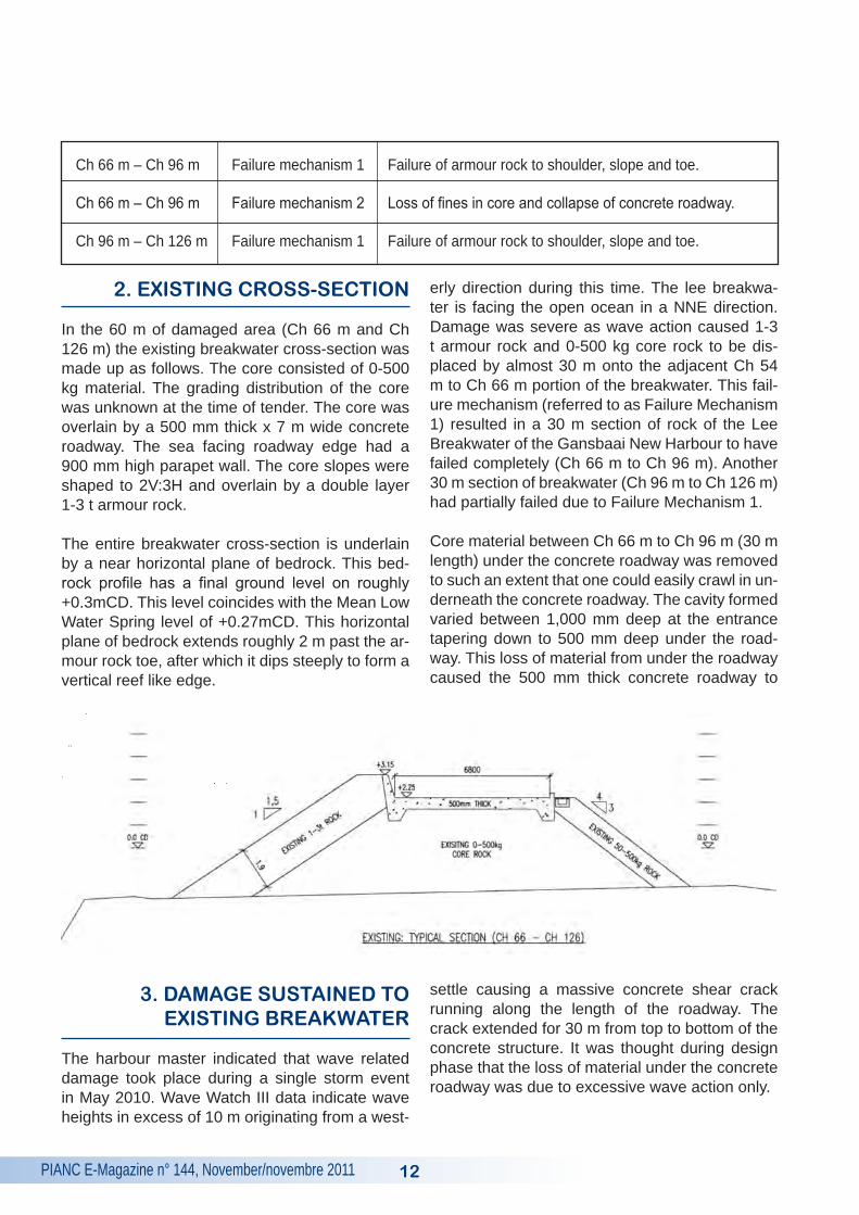
2. EXISTING CROSS-SECTION
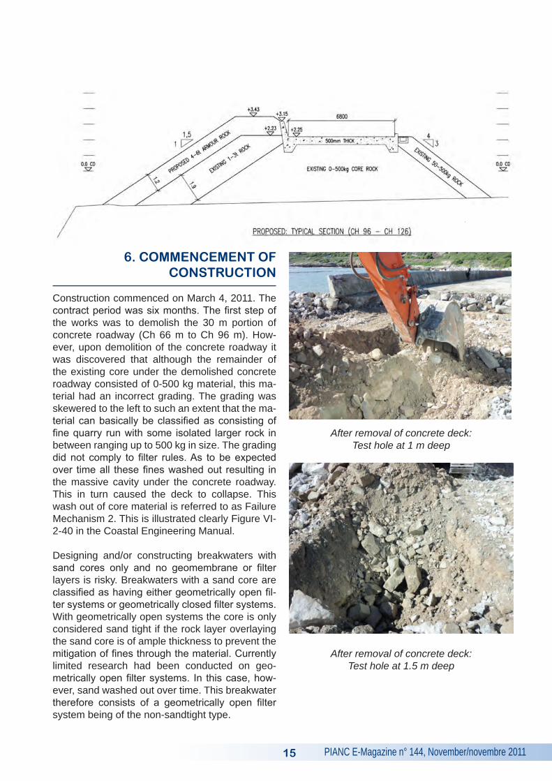
In the 60 m of damaged area (Ch 66 m and Ch 126 m) the existing breakwater cross-section was made up as follows. The core consisted of 0-500 kg material. The grading distribution of the core was unknown at the time of tender. The core was overlain by a 500 mm thick x 7 m wide concrete roadway. The sea facing roadway edge had a 900 mm high parapet wall. The core slopes were shaped to 2V:3H and overlain by a double layer 1-3 t armour rock.
The entire breakwater cross-section is underlain by a near horizontal plane of bedrock. This bed-rock profile has a final ground level on roughly +0.3mCD. This level coincides with the Mean Low Water Spring level of +0.27mCD. This horizontal plane of bedrock extends roughly 2 m past the ar-mour rock toe, after which it dips steeply to form a vertical reef like edge.
3. DAMAGE SUSTAINED TO EXISTING BREAkWATER
The harbour master indicated that wave related damage took place during a single storm event in May 2010. Wave Watch III data indicate wave heights in excess of 10 m originating from a west-
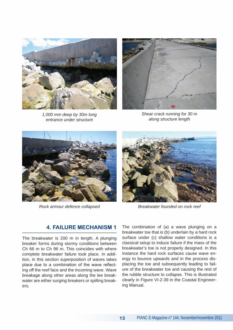
erly direction during this time. The lee breakwa-ter is facing the open ocean in a NNE direction. Damage was severe as wave action caused 1-3 t armour rock and 0-500 kg core rock to be dis-placed by almost 30 m onto the adjacent Ch 54 m to Ch 66 m portion of the breakwater. This fail-ure mechanism (referred to as Failure Mechanism 1) resulted in a 30 m section of rock of the Lee Breakwater of the Gansbaai New Harbour to have failed completely (Ch 66 m to Ch 96 m). Another 30 m section of breakwater (Ch 96 m to Ch 126 m) had partially failed due to Failure Mechanism 1. Core material between Ch 66 m to Ch 96 m (30 m length) under the concrete roadway was removed to such an extent that one could easily crawl in un-derneath the concrete roadway. The cavity formed varied between 1,000 mm deep at the entrance tapering down to 500 mm deep under the road-way. This loss of material from under the roadway caused the 500 mm thick concrete roadway to
settle causing a massive concrete shear crack running along the length of the roadway. The crack extended for 30 m from top to bottom of the concrete structure. It was thought during design phase that the loss of material under the concrete roadway was due to excessive wave action only.
12
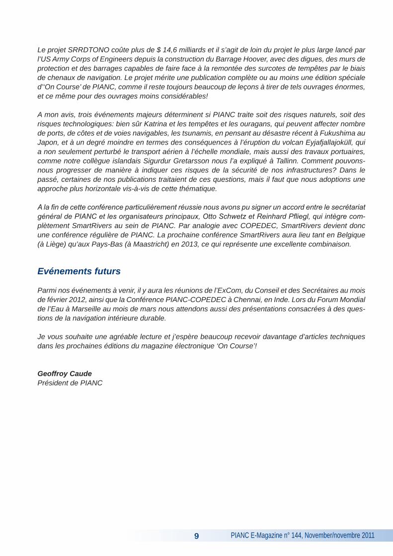
Ch 66 m – Ch 96 m Failure mechanism 1 Failure of armour rock to shoulder, slope and toe.
Ch 66 m – Ch 96 m Failure mechanism 2 Loss of fines in core and collapse of concrete roadway.
Ch 96 m – Ch 126 m Failure mechanism 1 Failure of armour rock to shoulder, slope and toe.
PIANC E-Magazine n° 144, November/novembre 201113
4. FAILURE MEChANISM 1
The breakwater is 200 m in length. A plunging breaker forms during stormy conditions between Ch 66 m to Ch 96 m. This coincides with where complete breakwater failure took place. In addi-tion, in this section superposition of waves takes place due to a combination of the wave reflect-ing off the reef face and the incoming wave. Wave breakage along other areas along the lee break-water are either surging breakers or spilling break-ers.
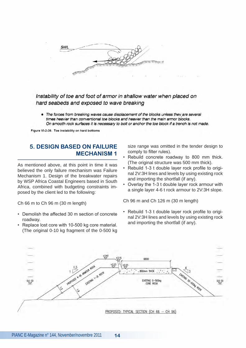
The combination of (a) a wave plunging on a breakwater toe that is (b) underlain by a hard rock surface under (c) shallow water conditions is a classical setup to induce failure if the mass of the breakwater’s toe is not properly designed. In this instance the hard rock surfaces cause wave en-ergy to bounce upwards and in the process dis-placing the toe and subsequently leading to fail-ure of the breakwater toe and causing the rest of the rubble structure to collapse. This is illustrated clearly in Figure VI-2-39 in the Coastal Engineer-ing Manual.
1,000 mm deep by 30m long entrance under structure
Shear crack running for 30 m along structure length
Rock armour defence collapsed Breakwater founded on rock reef
PIANC E-Magazine n° 144, November/novembre 2011 14
5. DESIGN BASED ON FAILURE MEChANISM 1
As mentioned above, at this point in time it was believed the only failure mechanism was Failure Mechanism 1. Design of the breakwater repairs by WSP Africa Coastal Engineers based in South Africa, combined with budgeting constraints im-posed by the client led to the following:
Ch 66 m to Ch 96 m (30 m length)
• Demolish the affected 30 m section of concrete roadway.
• Replace lost core with 10-500 kg core material. (The original 0-10 kg fragment of the 0-500 kg
size range was omitted in the tender design to comply to filter rules).
• Rebuild concrete roadway to 800 mm thick. (The original structure was 500 mm thick).
• Rebuild 1-3 t double layer rock profile to origi-nal 2V:3H lines and levels by using existing rock and importing the shortfall (if any).
• Overlay the 1-3 t double layer rock armour with a single layer 4-6 t rock armour to 2V:3H slope.
Ch 96 m and Ch 126 m (30 m length)
• Rebuild 1-3 t double layer rock profile to origi-nal 2V:3H lines and levels by using existing rock and importing the shortfall (if any).
PIANC E-Magazine n° 144, November/novembre 2011
6. COMMENCEMENT OF CONSTRUCTION
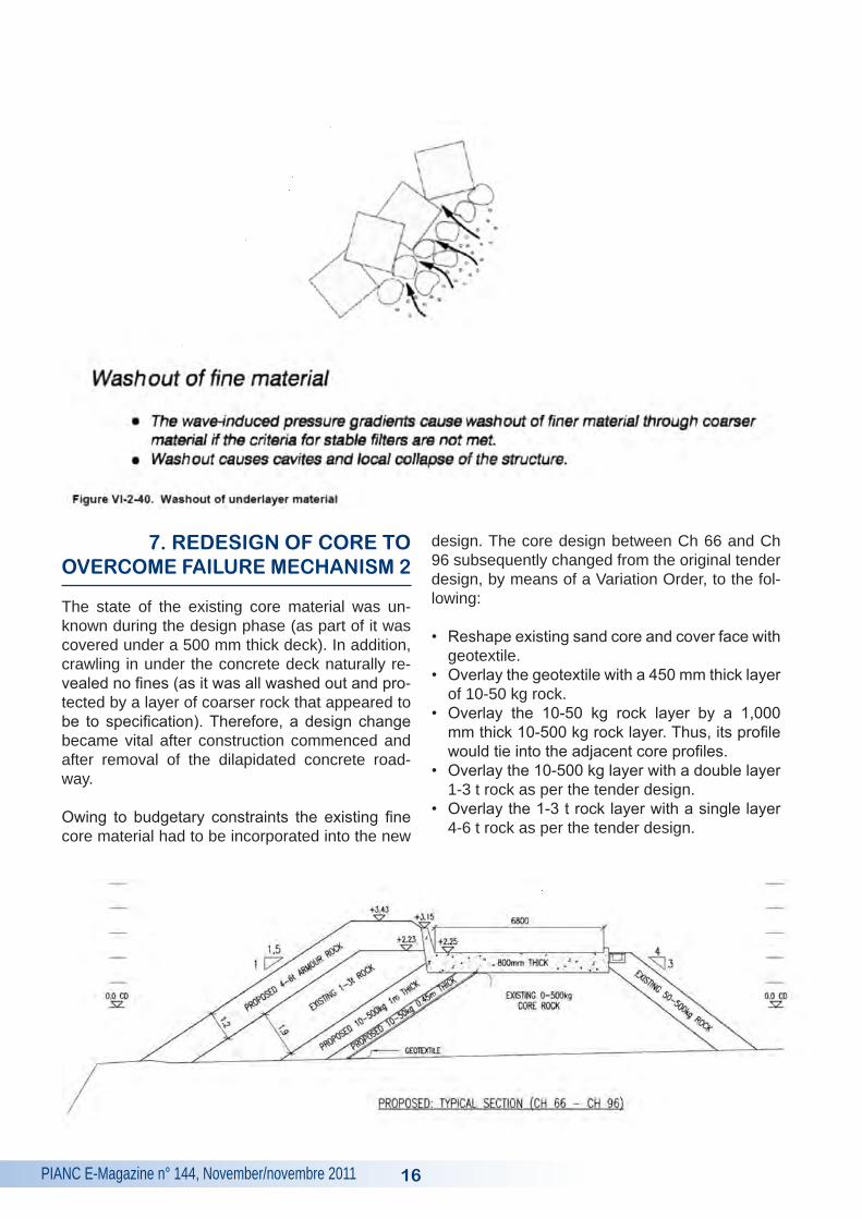
Construction commenced on March 4, 2011. The contract period was six months. The first step of the works was to demolish the 30 m portion of concrete roadway (Ch 66 m to Ch 96 m). How-ever, upon demolition of the concrete roadway it was discovered that although the remainder of the existing core under the demolished concrete roadway consisted of 0-500 kg material, this ma-terial had an incorrect grading. The grading was skewered to the left to such an extent that the ma-terial can basically be classified as consisting of fine quarry run with some isolated larger rock in between ranging up to 500 kg in size. The grading did not comply to filter rules. As to be expected over time all these fines washed out resulting in the massive cavity under the concrete roadway. This in turn caused the deck to collapse. This wash out of core material is referred to as Failure Mechanism 2. This is illustrated clearly Figure VI-2-40 in the Coastal Engineering Manual.
Designing and/or constructing breakwaters with sand cores only and no geomembrane or filter layers is risky. Breakwaters with a sand core are classified as having either geometrically open fil-ter systems or geometrically closed filter systems. With geometrically open systems the core is only considered sand tight if the rock layer overlaying the sand core is of ample thickness to prevent the mitigation of fines through the material. Currently limited research had been conducted on geo-metrically open filter systems. In this case, how-ever, sand washed out over time. This breakwater therefore consists of a geometrically open filter system being of the non-sandtight type.
After removal of concrete deck: Test hole at 1 m deep
After removal of concrete deck: Test hole at 1.5 m deep
15
PIANC E-Magazine n° 144, November/novembre 2011
7. REDESIGN OF CORE TO OVERCOME FAILURE MEChANISM 2
The state of the existing core material was un-known during the design phase (as part of it was covered under a 500 mm thick deck). In addition, crawling in under the concrete deck naturally re-vealed no fines (as it was all washed out and pro-tected by a layer of coarser rock that appeared to be to specification). Therefore, a design change became vital after construction commenced and after removal of the dilapidated concrete road-way.
Owing to budgetary constraints the existing fine core material had to be incorporated into the new
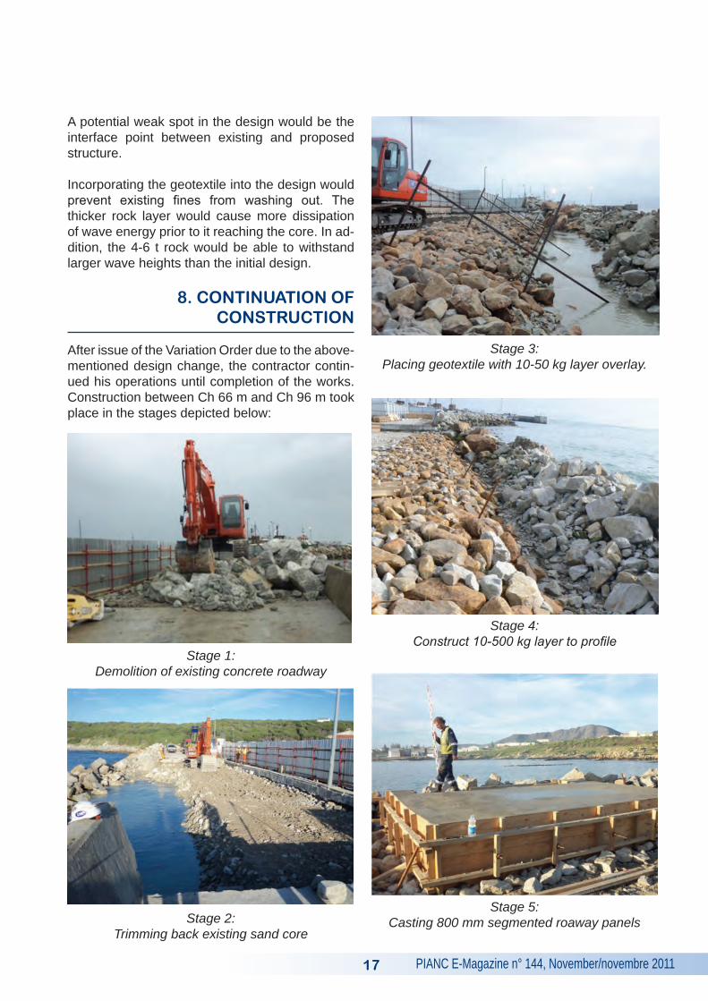
design. The core design between Ch 66 and Ch 96 subsequently changed from the original tender design, by means of a Variation Order, to the fol-lowing:
• Reshape existing sand core and cover face with geotextile.
• Overlay the geotextile with a 450 mm thick layer of 10-50 kg rock.
• Overlay the 10-50 kg rock layer by a 1,000 mm thick 10-500 kg rock layer. Thus, its profile would tie into the adjacent core profiles.
• Overlay the 10-500 kg layer with a double layer 1-3 t rock as per the tender design.
• Overlay the 1-3 t rock layer with a single layer 4-6 t rock as per the tender design.
16
PIANC E-Magazine n° 144, November/novembre 2011
A potential weak spot in the design would be the interface point between existing and proposed structure.
Incorporating the geotextile into the design would prevent existing fines from washing out. The thicker rock layer would cause more dissipation of wave energy prior to it reaching the core. In ad-dition, the 4-6 t rock would be able to withstand larger wave heights than the initial design.
8. CONTINUATION OF CONSTRUCTION
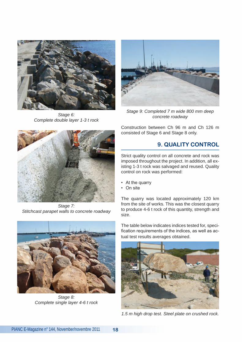
After issue of the Variation Order due to the above- mentioned design change, the contractor contin-ued his operations until completion of the works. Construction between Ch 66 m and Ch 96 m took place in the stages depicted below:
Stage 1: Demolition of existing concrete roadway
Stage 2: Trimming back existing sand core
Stage 3: Placing geotextile with 10-50 kg layer overlay.
Stage 4: Construct 10-500 kg layer to profile
Stage 5: Casting 800 mm segmented roaway panels
17
PIANC E-Magazine n° 144, November/novembre 2011
Stage 6: Complete double layer 1-3 t rock
Stage 7: Stitchcast parapet walls to concrete roadway
Stage 8: Complete single layer 4-6 t rock
Stage 9: Completed 7 m wide 800 mm deep concrete roadway
Construction between Ch 96 m and Ch 126 m consisted of Stage 6 and Stage 8 only.
9. QUALITY CONTROL
Strict quality control on all concrete and rock was imposed throughout the project. In addition, all ex-isting 1-3 t rock was salvaged and reused. Quality control on rock was performed:
• At the quarry• On site
The quarry was located approximately 120 km from the site of works. This was the closest quarry to produce 4-6 t rock of this quantity, strength and size.
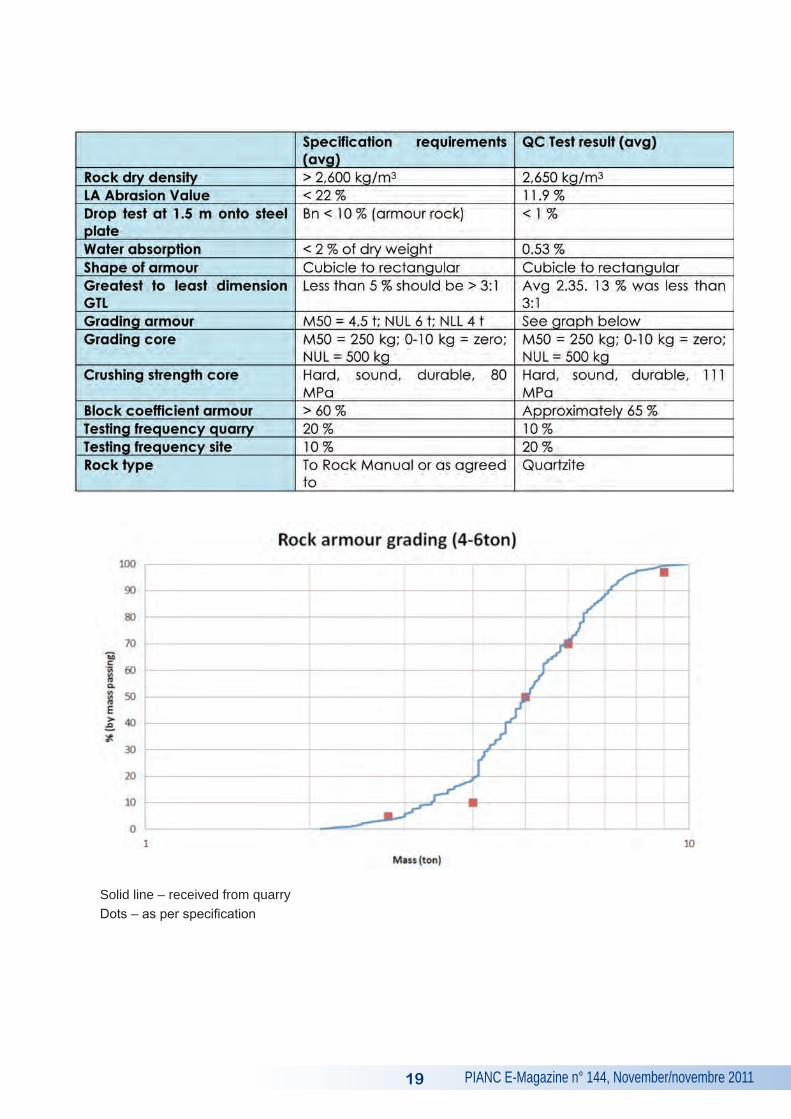
The table below indicates indices tested for, speci-fication requirements of the indices, as well as ac-tual test results averages obtained.
1.5 m high drop test. Steel plate on crushed rock.
18
PIANC E-Magazine n° 144, November/novembre 201119
Solid line – received from quarryDots – as per specification
PIANC E-Magazine n° 144, November/novembre 2011 20
10. PROGRAMME
The Contractor, Guerrini Marine Construction, based in South Africa, performed good work and completed the project on time. The contract com-menced on March 4, 2011 and was completed on September 5, 2011. The actual contract period was therefore six months which matched the ten-der construction period. The only variation order on the project was the design change due to un-
foreseen core material sizes.
11. REFERENCES
CIRIA (2006): “C683, The Rock Manual. The Use of Rock in Hydraulic Engineering”, 2nd Edition, (2007), Chapter 3. Engineer Manual (EM) 1110 – 2 – 1100, Coastal Engineering Manual (CEM), Part VI.
Gansbaai’s New Fishing Harbour is located in an area along the South African coastline subject to severe wave conditions. It is located approxi-mately 65 km from the southernmost tip of Africa. Emergency repairs became vital when sections of the leeward breakwater failed. A total of 60 m (Ch 66 to Ch 126) of breakwater had failed by March 2011 when the contractor, Guerrini Marine Con-struction, based in South Africa, arrived on site.
Along the first 30 m (Ch 66 to Ch 96) of this 60 m section of failed breakwater rock armour was displaced over a distance of 30 m from the break-water due to severe wave action in May 2010. Wave breaking along this section is in the form of plunging breakers on a hard rock bed (Failure Mechanism 1). In addition, the original core that predominantly consisted of fine material unpro-tected by a geomembrane had washed out from the breakwater core (Failure Mechanism 2). This resulted in a massive cavity 30 m long by 0.5 m to 1 m deep forming under the concrete roadway. Subsequently, the concrete roadway started to collapse into this cavity.
Along the second 30 m (Ch 96 to Ch 126) of this 60 m section of failed breakwater armour rock was displaced downwards from the toe, slope and crest areas of the breakwater. This in turn exposed the underlying core. In addition, the parapet wall was exposed and had to absorb direct wave impact.
The client, the Department of Public Works, acted swiftly and blocked off access to the breakwater and fast tracked the design, tender and procure-ment phase in order to get the contractor on site as soon as possible. Combining budgetary con-
straints and innovative design by WSP Africa Coastal Engineers, based in Stellenbosch, South Africa, the following solutions were catered for.
In general:
• For sustainability reasons WSP Coastal decid-ed to salvage and re-use all existing 1-3 t rock.
Along the first 30 m of damage sustained (Ch 66 to Ch 96):
• Demolish existing concrete roadway.• Trim back existing sandy core and overlay with
geomembrane, 10-50 kg rock and 10-500 kg rock.
• Rebuild concrete roadway to 800 mm thickness and stichcast precast parapet walls to road-way.
• Reconstruct original 1-3 t double rock protec-tion.
• Construct new single layer 4-6 t armour rock.
Along the second 30m of damage sustained (Ch 96 to Ch 126):
• Salvage and reconstruct original 1-3 t double rock protection.
• Construct new single layer 4-6 t armour rock.
The contract commenced on March 4, 2011 and was completed on September 5, 2011. The tender contract duration was six months. The contractor did well to complete the project within this time frame.
SUMMARY
PIANC E-Magazine n° 144, November/novembre 201121
Le nouveau port de pêche de Gansbaai est si-tué dans une zone le long du littoral sud-africain sujette à des conditions de houles sévères. Il est situé approximativement à 65 km de la pointe la plus au sud de l’Afrique. Les réparations d’urgence sont devenues nécessaires quand le talus arrière de la digue rompit. Un total de 60 m (Ch 66 à Ch 126) de digue avait rompu en Mars 2011 quand l’entrepreneur, Guerrini Marine Construction est arrivé sur le site.
Sur les trente premiers mètres (Ch 66 à Ch 96) des soixante du linéaire endommagé, les enro-chements ont été déplacés sur une distance de 30 mètres depuis la digue en raison des fortes actions de la houle en Mai 2010. Le déferlement des vagues le long de ce linéaire est du type plongeant sur un socle rocheux (mécanisme de rupture 1). En outre, le noyau initial de la digue, qui est constitué majoritairement de matériau fin non protégé par une géomembrane, a été lessivé: des matériaux ont été extraits du noyau (mécan-isme de rupture 2). Cela a eu pour conséquence une cavité importante de 30 m de long et profonde de 50 cm à 1 m, formée sous la route en béton. Par conséquent, cette dernière a commencé à s’effondrer dans la cavité.
Sur les 30 m suivants (Ch 96 à Ch 126), les en-rochements provenant du pied, de la pente et de la crête ont été déplacés vers le bas. Cela exposa le noyau sous-jacent. De plus, le mur de couron-nement fut exposé et encaissa directement les impacts des vagues.
Le maître d’ouvrage, le Département des Travaux Publics, a agi rapidement et a rendu inaccessible la digue. Il lança rapidement les phases d’études et d’appels d’offres pour trouver une entreprise de travaux le plus rapidement possible. En prenant en compte les contraintes budgétaires et la con-ception innovante proposée par WSP Coastal Af-rica Engineers, basé à Stellenbosch en Afrique du Sud, les solutions suivantes furent proposées.
Sur tout le linéaire:
• Pour des raisons de développement durable, WSP Coastal a décidé de récupérer et réutiliser tous les enrochements de 1-3 t.
Sur les 30 premiers mètres de dommages (Ch 66 à Ch 96):
• Démolir la route en béton existante.• Régaler l’ancien noyau en sable et le couvrir
avec une géomembrane puis d’enrochement de calibre 10-50 kg et 10-500 kg.
• Reconstruire la route d’une épaisseur de 800 mm et un mur de couronnement en éléments préfabriqués.
• Reconstruire à l’original la double couche d’enrochements protection.
• Construire une nouvelle couche simple d’enrochements de carapace de calibre 4-6 t.
Sur les seconds 30 mètres de dommages (Ch 96 à Ch 126):
• Récupération et reconstruction de la double couche initiale en enrochements de protection de calibre 1-3 t.
• Construire une nouvelle couche simple d’enrochements de carapace de calibre 4-6 t.
Les travaux ont commencé le 4 mars 2011 et ont été réceptionnés le 5 septembre 2011. L’offre pré-voyait une réalisation en 6 mois. L’entrepreneur a terminé son projet dans les délais.
RéSUMé
PIANC E-Magazine n° 144, November/novembre 2011 22
Der neue Fischereihafen von Gansbaai befindet sich ca. 65 km von der Südspitze Afrikas an einer Küste, die einem rauen Wellenklima ausgesetzt ist. In März 2011 waren bereits 60 m des Wellen-brechers zerstört.
Auf den ersten 30 m war die Gesteinsabdeckung durch den starken Wellengang im Mai 2010 mehr als 30 m weit vom Wellenbrecherkörper weg-gespült. Die Wellen treffen in diesem Abschnitt in Form von Sturzbrechern auf eine Festgesteinss-chicht auf (Versagens-mechanismus 1). Zusätzlich wurde der ursprüngliche Dammkern, der vorwieg-end aus Feinmaterial ohne Geomembranschutz bestand, herausgespült (Versagensmechanismus 2). Dies führte zu einer Aushöhlung um 0,5 bis 1 m Tiefe über eine Länge von 30 m unter der Be-tonstraße, die daraufhin einzubrechen begann. Auf den nächsten 30 m war das gesamte Stein-deckwerk vom Fuß, von der Böschung und von der Krone des Wellenbrechers weggerutscht, so dass der Dammkern freilag. Zudem war die Be-grenzungsmauer der Betonstraße freigelegt und der direkten Welleneinwirkung ausgesetzt. Allgemeines:
• Aus Gründen der Nachhaltigkeit beschloss WSP Coastal das gesamte vorhandene Gesteinsma-terial (1 bis 3 t) zu bergen und wieder zu ver-wenden.
Sanierung:
Auf den ersten 30 m der beschädigten Strecke (Ch 66 bis Ch 96):
• Rückbau der Betonstraße.• Neueinbau des vorhandenen Sandkerns und
Abdeckung mit einer Geomembran/Gestein-schicht (10-50 kg und 10-500 kg Steine).
• Neubau der Betonstraße mit einer Schichtdicke von 800 mm und vorgefertigten Brüstungswän-den
• Rekonstruktion der ursprünglichen 1-3 t dop-pelten Steinschutzschicht.
• Aufbau einer neuen einlagigen Deckschicht mit 4-6 t Steinen.
Auf der weiteren 30-m Schadstrecke (Ch 96 bis Ch 126):
• Bergung und Rekonstruktion der ursprüngli-chen 1-3 t doppelten Steinschutzschicht.
• Aufbau einer neuen einlagigen Deckschicht mit 4-6 t Steinen.
Die Bauzeit begann am 4. März 2011 und endete am 5. September 2011.
ZUSAMMENFASSUNG
PIANC E-Magazine n° 144, November/novembre 201123
SOME ThOUGhTS ON ThE ECONOMICS OF DRY DOCkS
kEY WORDS
Dry Docks, Ship Repair, Economics
MOTS-CLEFS
Installations de radoub, réparation navale, écono-mie
1. INTRODUCTION
The following comments are a distillation of forty years of experience with dry docks and the tech-nology of dry docks. As such they are pragmatic and much of the basis has been developed as part of feasibility studies or the development of ac-tual projects. Some aspects have been included in refereed papers and are hence persuasive but a word of caution: these comments have not yet been formally examined in a scientific way. The most significant aspect I foresee comes from the relatively simplistic presentation given here. In practice there may well be a great deal of varia-tion from individual case to individual case.
2. ECONOMIC BASIS OF DRY DOCkING
The economics of dry docks are somewhat pecu-liar. As a rule of thumb, ship owners will accept a docking fee that does not exceed 10 % of the overall cost of the work done during the docking without complaining. Generally, ships are mo-
bile and they will begin to think of going to other ports if the charges rise too high. Where the site is relatively isolated, the dock can get away with somewhat higher charges before resistance sets in. Docking charges at this 10 % level are gener-ally sufficient to cover operating costs and running maintenance. But it is completely inadequate to cover the amortisation of the capital cost. Again, as a rule, dock costs are scale dependent, i.e. both the capital cost and the operating and main-tenance costs, expressed as cost per tonne of ca-pacity, are least for large docks and greatest for small docks.
Ship repairers can afford to acquire their own docks. If they own the dock, they not only control their business, they control the whole of the mon-ies spent on ship repair during docking and the profit on these monies. They can afford to plough back a significant portion of their profit in amor-tising the dock. Not only does the money stay in the business as capital asset, the tax benefits of the write-off of this investment create a gearing ef-fect that increases the apparent amount of money invested. This does mean that the valuation of a ship repair company, owning its own dry dock, is characterised by a very large single asset.
Alternatively, a dry dock facility can be a ‘common user facility’ by which is meant a facility where anyone, boat owner, ship repairer or agent etc. can bring a ship to dock; where anyone, the owner himself or any ship repairer or contractor duly ap-pointed can work on the vessel.
by
KEITH MACKIE
Consulting Coastal & Harbour Engineer36 Fishermans BendLlandudno 7806 Cape TownSouth Africa
Tel.: +27 21 790 2263E-mail: [email protected]
PIANC E-Magazine n° 144, November/novembre 2011 24
If a dry dock is unencumbered by any capital cost and is endowed to some extent to assist with oc-casional major maintenance costs, then it can op-erate as a viable but not very profitable common user facility. This unlikely scenario could perhaps occur where a military dock, no longer needed, is donated to a community or to a training facility teaching ship repair and dry dock operation.
To any fleet whether it be shipping, fishing, under-sea mining, oil exploration or any other function and the community it supports, a dry dock, how-ever it is owned, is a major communal asset. Not only does it make possible the economic activity of the fleet that sustains the community – ships cannot continue to operate without the back up of dry docks and ship repair – it also provides ship repair as an added source of employment for the community.
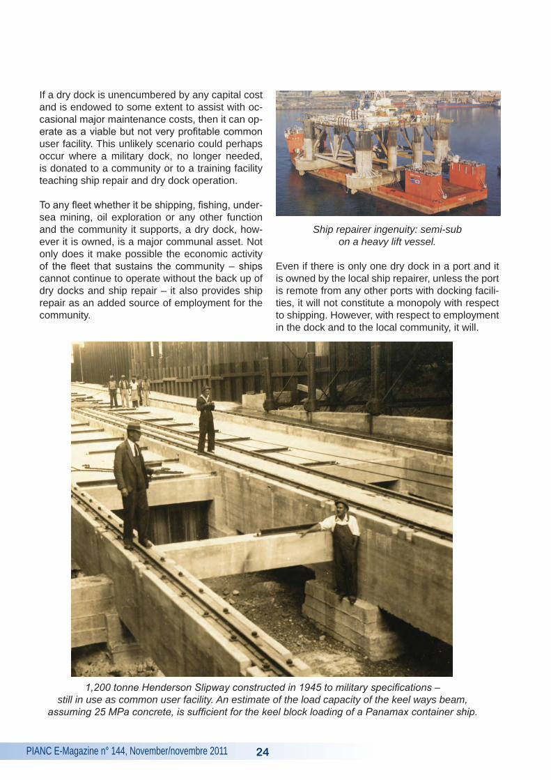
Ship repairer ingenuity: semi-sub on a heavy lift vessel.
Even if there is only one dry dock in a port and it is owned by the local ship repairer, unless the port is remote from any other ports with docking facili-ties, it will not constitute a monopoly with respect to shipping. However, with respect to employment in the dock and to the local community, it will.
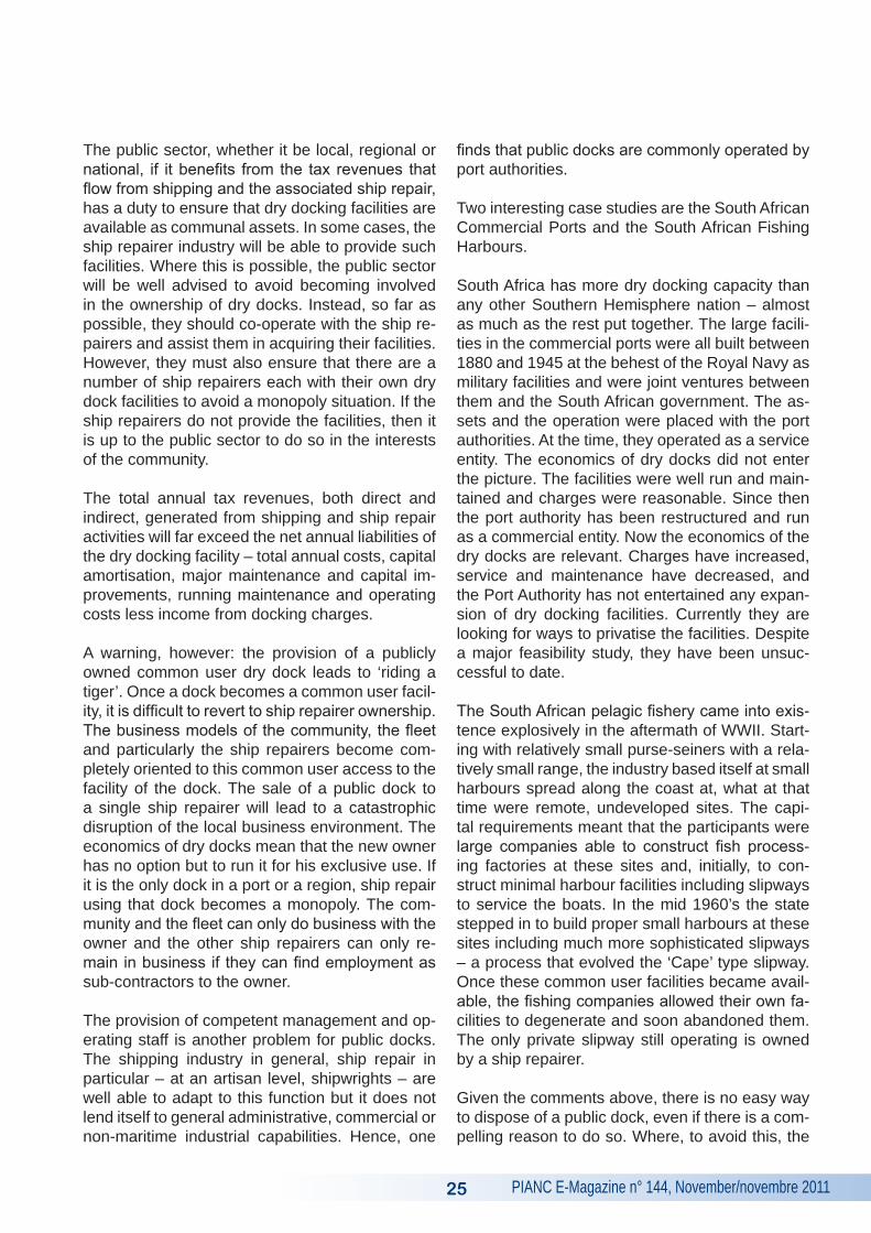
1,200 tonne Henderson Slipway constructed in 1945 to military specifications – still in use as common user facility. An estimate of the load capacity of the keel ways beam,
assuming 25 MPa concrete, is sufficient for the keel block loading of a Panamax container ship.
PIANC E-Magazine n° 144, November/novembre 201125
The public sector, whether it be local, regional or national, if it benefits from the tax revenues that flow from shipping and the associated ship repair, has a duty to ensure that dry docking facilities are available as communal assets. In some cases, the ship repairer industry will be able to provide such facilities. Where this is possible, the public sector will be well advised to avoid becoming involved in the ownership of dry docks. Instead, so far as possible, they should co-operate with the ship re-pairers and assist them in acquiring their facilities. However, they must also ensure that there are a number of ship repairers each with their own dry dock facilities to avoid a monopoly situation. If the ship repairers do not provide the facilities, then it is up to the public sector to do so in the interests of the community.
The total annual tax revenues, both direct and indirect, generated from shipping and ship repair activities will far exceed the net annual liabilities of the dry docking facility – total annual costs, capital amortisation, major maintenance and capital im-provements, running maintenance and operating costs less income from docking charges.
A warning, however: the provision of a publicly owned common user dry dock leads to ‘riding a tiger’. Once a dock becomes a common user facil-ity, it is difficult to revert to ship repairer ownership. The business models of the community, the fleet and particularly the ship repairers become com-pletely oriented to this common user access to the facility of the dock. The sale of a public dock to a single ship repairer will lead to a catastrophic disruption of the local business environment. The economics of dry docks mean that the new owner has no option but to run it for his exclusive use. If it is the only dock in a port or a region, ship repair using that dock becomes a monopoly. The com-munity and the fleet can only do business with the owner and the other ship repairers can only re-main in business if they can find employment as sub-contractors to the owner.
The provision of competent management and op-erating staff is another problem for public docks. The shipping industry in general, ship repair in particular – at an artisan level, shipwrights – are well able to adapt to this function but it does not lend itself to general administrative, commercial or non-maritime industrial capabilities. Hence, one
finds that public docks are commonly operated by port authorities.
Two interesting case studies are the South African Commercial Ports and the South African Fishing Harbours.
South Africa has more dry docking capacity than any other Southern Hemisphere nation – almost as much as the rest put together. The large facili-ties in the commercial ports were all built between 1880 and 1945 at the behest of the Royal Navy as military facilities and were joint ventures between them and the South African government. The as-sets and the operation were placed with the port authorities. At the time, they operated as a service entity. The economics of dry docks did not enter the picture. The facilities were well run and main-tained and charges were reasonable. Since then the port authority has been restructured and run as a commercial entity. Now the economics of the dry docks are relevant. Charges have increased, service and maintenance have decreased, and the Port Authority has not entertained any expan-sion of dry docking facilities. Currently they are looking for ways to privatise the facilities. Despite a major feasibility study, they have been unsuc-cessful to date.
The South African pelagic fishery came into exis-tence explosively in the aftermath of WWII. Start-ing with relatively small purse-seiners with a rela-tively small range, the industry based itself at small harbours spread along the coast at, what at that time were remote, undeveloped sites. The capi-tal requirements meant that the participants were large companies able to construct fish process-ing factories at these sites and, initially, to con-struct minimal harbour facilities including slipways to service the boats. In the mid 1960’s the state stepped in to build proper small harbours at these sites including much more sophisticated slipways – a process that evolved the ‘Cape’ type slipway. Once these common user facilities became avail-able, the fishing companies allowed their own fa-cilities to degenerate and soon abandoned them. The only private slipway still operating is owned by a ship repairer.
Given the comments above, there is no easy way to dispose of a public dock, even if there is a com-pelling reason to do so. Where, to avoid this, the
PIANC E-Magazine n° 144, November/novembre 2011 26
asset is transferred to the port authority, more problems arise. The apparent value will inflate their asset register but, since the object is to pro-vide a common user facility, there will be no con-comitant return on investment and this in turn will reflect on the authority’s balance sheet.
The only practical way around this is to keep all the financials, asset, costs and incomes in the public domain and acquire the use of the site by
purchase or rent as appropriate. Operation and management of the docks and provision of tech-nical guidance on major maintenance or capital improvements can be provided on a contract ba-sis with the port authority or any other competent entity. If, however, the scope and number of dry docking facilities justifies it, a dedicated, compe-tent public institution can be established to handle all these functions and still provide dry docking on a common user basis.
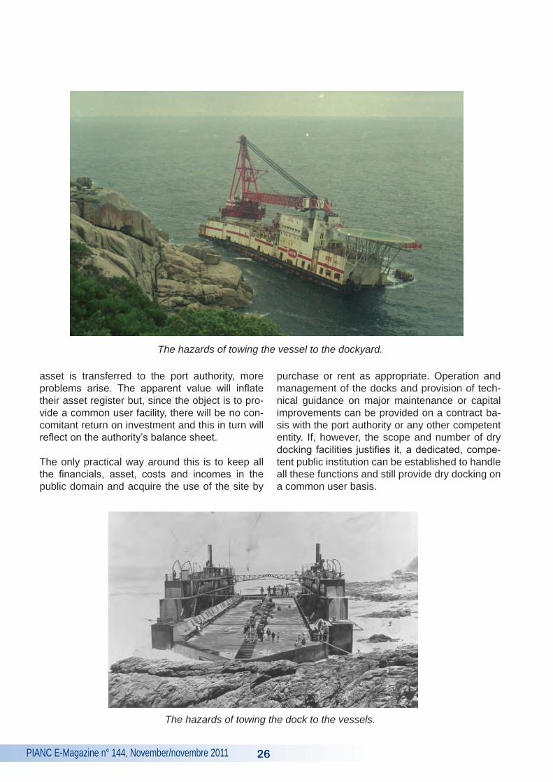
The hazards of towing the vessel to the dockyard.
The hazards of towing the dock to the vessels.
PIANC E-Magazine n° 144, November/novembre 201127
3. REFERENCES
Clark, E.: “Hydraulic Lift Graving Dock”, Min. Proc ICE Vol 25, 1865-66.
Mackie, K.P. (May 2010): “The 1890 Blackwood Screw Jack Shiplift, Barbados”, PIANC MMX, Liv-erpool.
Mackie, K.P. and Deane, R.F. (2006): “Issues in Dry Docking – Economics, Shiplifts, Slipways and Keel Blocks”, 31st PIANC Congress, Lisbon.
Mackie, K.P. (May 2007): “South African Dry Dock-ing Facilities”, Civil Engineering: SAICE, vol 15, no 5.
Mackie, K.P. (1999): “Small Mechanical Dry Dock-ing Systems”, Fifth International Conference on Coastal and Port Engineering in Developing Countries, Cape Town.
Although of a crude nature, a number of rules of thumb characterise the economics of dry docks quite reliably. These economics are dominated by the pattern of ownership of the dock. Almost in-evitably, either a dry docking facility is owned by a ship repairer who will have exclusive use of the
dock or it is owned by the public sector and run as a common user facility. The economics of these two systems are quite different. The failure to un-derstand these basics can cripple a proposal for a dry docking facility.
SUMMARY
Quelques règles de bases simples caractérisent bien l’économie des installations de radoub. Cette économie est dominée par le type de propriété de l’installation. Dans presque tous les cas les instal-lations sont soit la propriété d’un réparateur qui
en a l’usage exclusif, soit gérées comme un bien public. Les fonctionnements économiques de ces deux systèmes sont profondément différents. Une méconnaissance de ces fondamentaux peut faire perdre son intérêt à une installation de radoub.
RéSUMé
Die Wirtschaftlichkeit von Trockendocks läst sich grob anhand einiger Faustregeln charakterisieren. Trockendockanlagen befinden sich einerseits en-tweder im Besitz von Schiffsreparaturbetrieben, die dann die alleinigen Nutzer dieser Docks sind oder die Anlagen gehören zum öffentlichen Sek-
tor und werden allgemein genutzt. Diese beiden Systeme unterscheiden sich stark in ihrer Be-triebswirtschaft. Mangelndes Verständnis dieser Grundlagen kann zum Scheitern eines Vorhabens zur Schaffung bzw. zum Betrieb einer Trockend-ockanlage führen.
ZUSAMMENFASSUNG

PIANC E-Magazine n° 144, November/novembre 2011 28
PIANC E-Magazine n° 144, November/novembre 201129
STABILITY OF CROWN WALLS OF CUBE AND CUBIPOD ARMOURED MOUND BREAkWATERS
kEY WORDS
Crown Wall Forces, Crown Wall Stability, Break-water, Crown Wall Sliding, Cubipod
MOTS-CLEFS
Efforts sur les murs de couronnement, stabilité des murs de couronnement, glissement des murs de couronnement, Cubipod
1. INTRODUCTION
Breakwaters can generally be divided into two types: vertical and mound breakwaters. The for-mer reflect the wave energy, with the associated problems for navigation, but they are cheaper and more respectful of the environment than the mound ones. The latter absorb part of the wave energy, resisting wave action mainly by wave breaking.
Normally, mound breakwaters are crowned with a concrete superstructure resting on the mound lay-er and are partially protected by the armour layer. The aim is to reduce the amount of concrete used in armour layers and increase the crest freeboard while decreasing cost. Crown walls are attacked by wave impact and earth armour layer pressure, the former being the most important one due to the higher value.
Initially, the main layer of mound breakwaters consisted of quarrystone. As demand for space
in ports grew, it became necessary to place the breakwaters deeper. At greater depths, no quar-ry could provide heavy enough quarrystone, so prefabricated elements of concrete such as the Cube, the Tetrapode (1950) or the Dolo (1963) appeared.
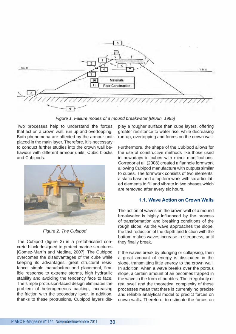
In a mound breakwater there are different types of failure modes, as shown in Figure 1 by Bruun (1985): extraction of armour units, overtopping, erosion of the toe, etc. There are four common types of failure affecting the crown wall:
1. Sliding is the most common failure mode. It happens when the horizontal force is greater than the friction resistance, which can be al-tered by ascending pressures.
2. Overturning happens when the unstabilising moments are larger than the stabilising ones.
3. Cracking refers to the deterioration of the ma-terial throughout its lifetime.
4. Geotechnical failure is the failure of the foun-dations. It is caused when the load transmitted is higher than the load of collapse of the foun-dations.
Failures modes 2 (overturning) and 3 (cracking) are easily solved by the proper design of the crown wall geometry. Failure mode 4 (geotechnical fail-ure) is related to the foundation soils rather than to the crown wall design; therefore, sliding is the most typical critical failure, since it requires build-ing the crown wall with sufficient weight.
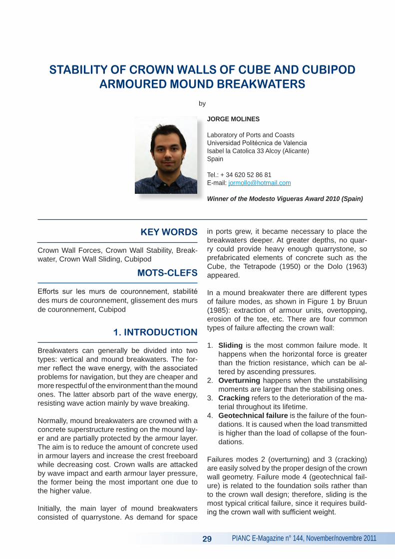
by
JORGE MOLINES
Laboratory of Ports and CoastsUniversidad Politécnica de ValenciaIsabel la Catolica 33 Alcoy (Alicante)Spain
Tel.: + 34 620 52 86 81E-mail: [email protected]
Winner of the Modesto Vigueras Award 2010 (Spain)
PIANC E-Magazine n° 144, November/novembre 2011 30
Two processes help to understand the forces that act on a crown wall: run up and overtopping. Both phenomena are affected by the armour unit placed in the main layer. Therefore, it is necessary to conduct further studies into the crown wall be-haviour with different armour units: Cubic blocks and Cubipods.
Figure 2. The Cubipod
The Cubipod (figure 2) is a prefabricated con-crete block designed to protect marine structures [Gómez-Martín and Medina, 2007]. The Cubipod overcomes the disadvantages of the cube while keeping its advantages: great structural resis-tance, simple manufacture and placement, flex-ible response to extreme storms, high hydraulic stability and avoiding the tendency face to face. The simple protrusion-faced design eliminates the problem of heterogeneous packing, increasing the friction with the secondary layer. In addition, thanks to these protrusions, Cubipod layers dis-
play a rougher surface than cube layers, offering greater resistance to water rise, while decreasing run-up, overtopping and forces on the crown wall.
Furthermore, the shape of the Cubipod allows for the use of constructive methods like those used in nowadays in cubes with minor modifications. Corredor et al. (2008) created a flanhole formwork allowing Cubipod manufacture with outputs similar to cubes. The formwork consists of two elements: a static base and a top formwork with six articulat-ed elements to fill and vibrate in two phases which are removed after every six hours.
1.1. Wave Action on Crown Walls
The action of waves on the crown wall of a mound breakwater is highly influenced by the process of transformation and breaking conditions of the rough slope. As the wave approaches the slope, the fast reduction of the depth and friction with the bottom makes waves increase in steepness, until they finally break.
If the waves break by plunging or collapsing, then a great amount of energy is dissipated in the slope, transmitting little energy to the crown wall. In addition, when a wave breaks over the porous slope, a certain amount of air becomes trapped in the wave in the form of bubbles. The irregularity of real swell and the theoretical complexity of these processes mean that there is currently no precise and reliable analytical model to predict forces on crown walls. Therefore, to estimate the forces on
Figure 1. Failure modes of a mound breakwater [Bruun, 1985]
PIANC E-Magazine n° 144, November/novembre 201131
crown walls, Froude similarity and physical model tests are used to obtain the empirically-related factors involved in the process and an empirical calculation method to estimate the forces.
The prediction models proposed over the years include:
1) Iribarren (1954) proposed triangular distribu-tions (see Figure 3a) for the dynamic and hy-drostatic pressures, based on the maximum horizontal crest speed after the wave breaks on the slope.
2) Jensen (1984) studied the influence of the wave height, period and sea level. Jensen (1984) concluded that the influence of sea level variations can be expressed as the berm free-board and that the horizontal force is directly proportional to Hs/As. The wave period shows a clear trend: when the period increases, the forces increase too.
Jensen‘s formulae should only be used when the input parameters are very similar to those reported in Jensen (1984), limiting their appli-cation to situations of moderate overtopping.
Jensen (1984) did not propose a distribution of pressures, so it is not possible to get the unstabilising moments, although overturning is not a critical failure mode.
3) Günback and Göcke (1984) proposed a meth-od to calculate the pressures based on run-up. They separated the action of the waves on the vertical wall into two simultaneous distribu-tions: a hydrostatic one extended up to the end of the wedge run-up representing the mass of water that hits the wall and a rectangular one associated with the kinetic energy of the wave (see Figure 3b). They proposed a triangular distribution for the up-lift forces.
4) Bradbury (1988) investigated the influence of the slope on the loads over the superstructure, but did not draw clear conclusions about its influence. The results support those reported by Jensen (1984), i.e. proportionality between force and wave height and an increase in the forces with the wave period.
5) Hamilton and Hall (1992) conducted a para-metric research through laboratory tests to de-termine crown wall stability when subjected to regular waves. Their main findings are:
• The increase in forces is directly proportion-al to wave height at moderate overtopping rates: from this point, the increase in forces decreases until approaching an horizontal asymptote.
• Forces increase with the period, but the au-thors do not provide clear conclusions.
• The smoother the slope, the lower the forc-es.
• Crown wall stability greatly decreases when placed just on the riprap (provided that the crown walls used in the tests conducted by Hamilton and Hall (1992) have a smooth base).
• The use of heels in the crown walls increas-es resistance to sliding compared to crown walls without heels; length is not relevant.
6) Pedersen and Burchart (1992) studied the in-fluence of certain parameters on the stability of the crown wall. Their conclusions are similar to those of Hamilton and Hall (1992) and Jensen (1984):
• The higher the wave height, the higher the load on the crown wall.
• The longer the period, the stronger the ac-tions on the crown wall.
• The Hs/As parameter displays a clear linear dependence with the force.
• Non-conclusive results are obtained regard-ing the influence of the berm width.
• Forces on crown walls depend on the area non-protected by the berm. When the height of the vertical wall is very high, a maximum value that depends only on the sea condi-tions and the sea level is reached.
7) Burchart (1993) presented a formula for force calculation based on the idea of Günback and Göcke (1984) extending the wedge run-up un-til the imaginary prolongation of the slope is reached. For simplicity, Burchart (1993) did not separate the force into an impulsive one and a hydrostatic one, but considered it as a fictitious hydrostatic force. Burchart (1993)
PIANC E-Magazine n° 144, November/novembre 2011
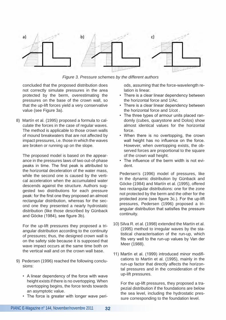
concluded that the proposed distribution does not correctly simulate pressures in the area protected by the berm, overestimating the pressures on the base of the crown wall, so that the up-lift forces yield a very conservative value (see Figure 3a).
8) Martín et al. (1995) proposed a formula to cal-culate the forces in the case of regular waves. The method is applicable to those crown walls of mound breakwaters that are not affected by impact pressures, i.e. those in which the waves are broken or running up on the slope.
The proposed model is based on the appear-ance in the pressures laws of two out-of-phase peaks in time. The first peak is attributed to the horizontal deceleration of the water mass, while the second one is caused by the verti-cal acceleration when the accumulated water descends against the structure. Authors sug-gested two distributions for each pressure peak: for the first one they proposed an almost rectangular distribution, whereas for the sec-ond one they presented a nearly hydrostatic distribution (like those described by Günback and Göcke (1984), see figure 3b).
For the up-lift pressures they proposed a tri-angular distribution according to the continuity of pressures; thus, the designed crown wall is on the safety side because it is supposed that wave impact occurs at the same time both on the vertical wall and on the crown wall base.
9) Pedersen (1996) reached the following conclu-sions:
• A linear dependency of the force with wave height exists if there is no overtopping. When overtopping begins, the force tends towards an asymptotic value.
• The force is greater with longer wave peri-
ods, assuming that the force-wavelength re-lation is linear.
• There is a clear linear dependency between the horizontal force and 1/Ac.
• There is a clear linear dependency between the horizontal force and 1/cot .
• The three types of armour units placed ran-domly (cubes, quarystone and Dolos) show almost identical values for the horizontal force.
• When there is no overtopping, the crown wall height has no influence on the force. However, when overtopping exists, the ob-served forces are proportional to the square of the crown wall height.
• The influence of the berm width is not evi-dent.
Pedersen’s (1996) model of pressures, like in the dynamic distribution by Günback and Göcke (1984) and Martín et al. (1995), offered two rectangular distributions: one for the zone not protected by the berm and the other for the protected zone (see figure 3c.). For the up-lift pressures, Pedersen (1996) proposed a tri-angular distribution that satisfies the pressure continuity.
10) Silva R. et al. (1998) extended the Martín et al. (1995) method to irregular waves by the sta-tistical characterisation of the run-up, which fits very well to the run-up values by Van der Meer (1988).
11) Martín et al. (1999) introduced minor modifi-cations to Martín et al. (1995), mainly in the run-up factor that directly affects the horizon-tal pressures and in the consideration of the up-lift pressures.
For the up-lift pressures, they proposed a tra-pezial distribution if the foundations are below the sea level, including the hydrostatic pres-sure corresponding to the foundation level.
32
Figure 3. Pressure schemes by the different authors
PIANC E-Magazine n° 144, November/novembre 201133
12) Camus and Flores (2004) evaluate the formu-lae by Günback and Göcke (1984), Jensen-Bradbury (1984, 1988), Pedersen (1996) and Martín et al. (1999). They conclude that the Pedersen (1996) method is the approach that best represents the maximum horizontal forc-es, whereas the methodology of Martín et al. (1999) best represents the physical phenom-enon of wave impact on the crown wall.
13) Berenguer and Baonza (2006) presented a formula to calculate forces on the crown wall based on laboratory tests. This formula con-siders the influence of the damage level in the main layer on the wave impact intensity on the crown wall. They do not propose any distribu-tion for the horizontal pressures, only a trian-gular distribution for the up-lift pressures.
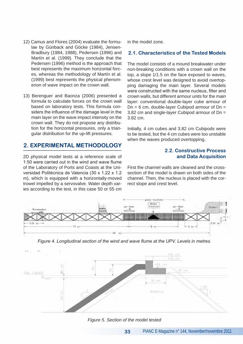
2. EXPERIMENTAL METhODOLOGY
2D physical model tests at a reference scale of 1:50 were carried out in the wind and wave flume of the Laboratory of Ports and Coasts at the Uni-versidad Politécnica de Valencia (30 x 1.22 x 1.2 m), which is equipped with a horizontally-moved trowel impelled by a servovalve. Water depth var-ies according to the test, in this case 50 or 55 cm
in the model zone.
2.1. Characteristics of the Tested Models
The model consists of a mound breakwater under non-breaking conditions with a crown wall on the top, a slope 1/1.5 on the face exposed to waves, whose crest level was designed to avoid overtop-ping damaging the main layer. Several models were constructed with the same nucleus, filter and crown walls, but different armour units for the main layer: conventional double-layer cube armour of Dn = 6 cm, double-layer Cubipod armour of Dn = 3.82 cm and single-layer Cubipod armour of Dn = 3.82 cm.
Initially, 4 cm cubes and 3.82 cm Cubipods were to be tested, but the 4 cm cubes were too unstable when the waves produced overtopping.
2.2. Constructive Process and Data Acquisition
First the channel walls are cleaned and the cross-section of the model is drawn on both sides of the channel. Then, the nucleus is placed with the cor-rect slope and crest level.
Figure 4. Longitudinal section of the wind and wave flume at the UPV. Levels in metres.
Figure 5. Section of the model tested
PIANC E-Magazine n° 144, November/novembre 2011 34
Next, on the top of the nucleus, the crown wall is placed and a filter constant thickness (about 6.7 cm) is also installed. In the protected area of the breakwater, heavy material is placed to avoid the washing of the filter and nucleus by overtopping.
Finally, the main layer is placed; it may consist of one or two layers, depending on the armour unit: Cubipods are placed in single and double layers, whereas cubes are only placed in double layers. When the double-layer breakwater is tested, the lower one is white, whereas the upper one is di-vided into bands of colours to easily identify where a piece has been removed. The elements are placed randomly, simulating the real crane place-ment (not placing them in a certain position). As a consequence, the double-layers cube and Cubi-pod armoured breakwater has a porosity of 37 % and the single-layer Cubipod armoured breakwa-ter has a porosity of 39 %.
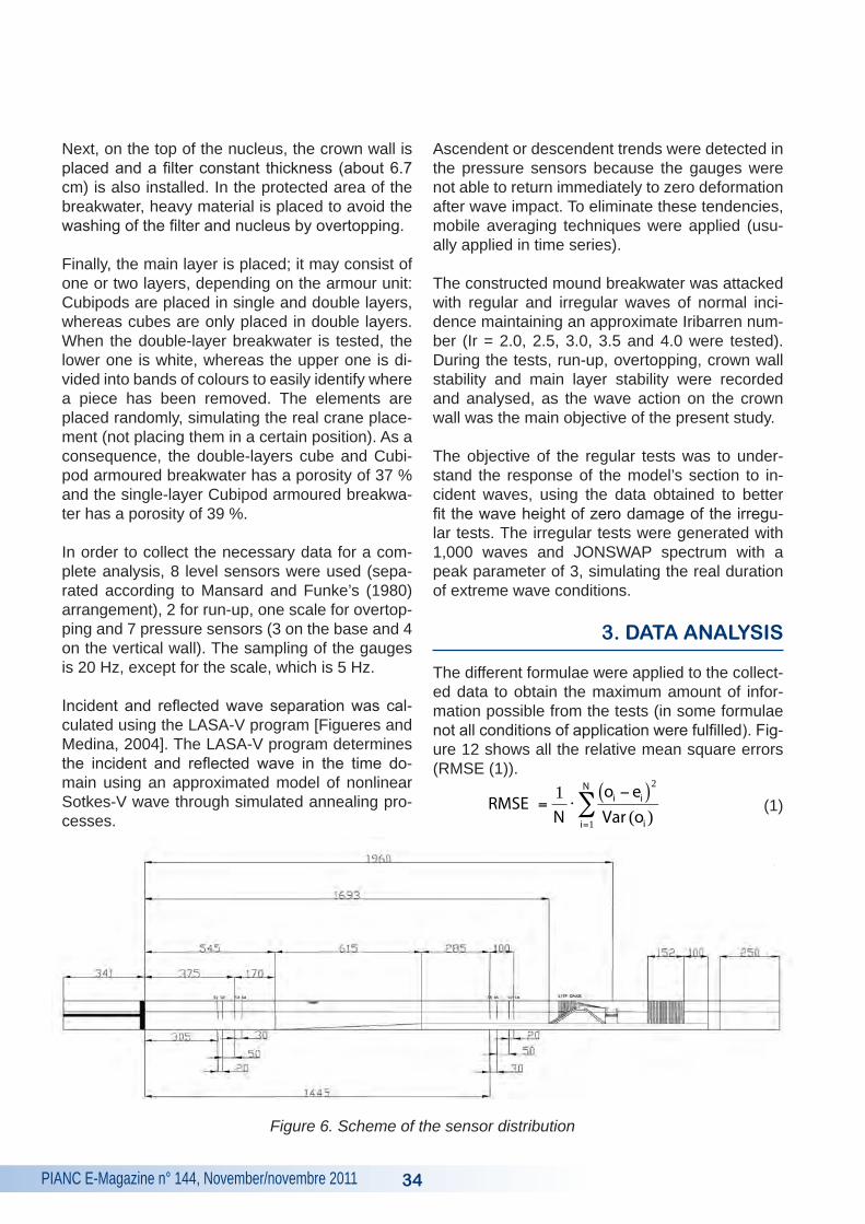
In order to collect the necessary data for a com-plete analysis, 8 level sensors were used (sepa-rated according to Mansard and Funke’s (1980) arrangement), 2 for run-up, one scale for overtop-ping and 7 pressure sensors (3 on the base and 4 on the vertical wall). The sampling of the gauges is 20 Hz, except for the scale, which is 5 Hz.
Incident and reflected wave separation was cal-culated using the LASA-V program [Figueres and Medina, 2004]. The LASA-V program determines the incident and reflected wave in the time do-main using an approximated model of nonlinear Sotkes-V wave through simulated annealing pro-cesses.
Ascendent or descendent trends were detected in the pressure sensors because the gauges were not able to return immediately to zero deformation after wave impact. To eliminate these tendencies, mobile averaging techniques were applied (usu-ally applied in time series).
The constructed mound breakwater was attacked with regular and irregular waves of normal inci-dence maintaining an approximate Iribarren num-ber (Ir = 2.0, 2.5, 3.0, 3.5 and 4.0 were tested). During the tests, run-up, overtopping, crown wall stability and main layer stability were recorded and analysed, as the wave action on the crown wall was the main objective of the present study.
The objective of the regular tests was to under-stand the response of the model’s section to in-cident waves, using the data obtained to better fit the wave height of zero damage of the irregu-lar tests. The irregular tests were generated with 1,000 waves and JONSWAP spectrum with a peak parameter of 3, simulating the real duration of extreme wave conditions.
3. DATA ANALYSIS
The different formulae were applied to the collect-ed data to obtain the maximum amount of infor-mation possible from the tests (in some formulae not all conditions of application were fulfilled). Fig-ure 12 shows all the relative mean square errors (RMSE (1)).
€
RMSE =1N
⋅oi − ei( )2
Var (oi )i=1
N
∑
Figure 6. Scheme of the sensor distribution
(1)
PIANC E-Magazine n° 144, November/novembre 201135
None of the analysed models satisfactorily repre-sented both the horizontal and the up-lift forces; thus, a new methodology is proposed. First, the most relevant variables of the process are studied and then the pertinent formulae are given using statistical studies and pruned neural networks.
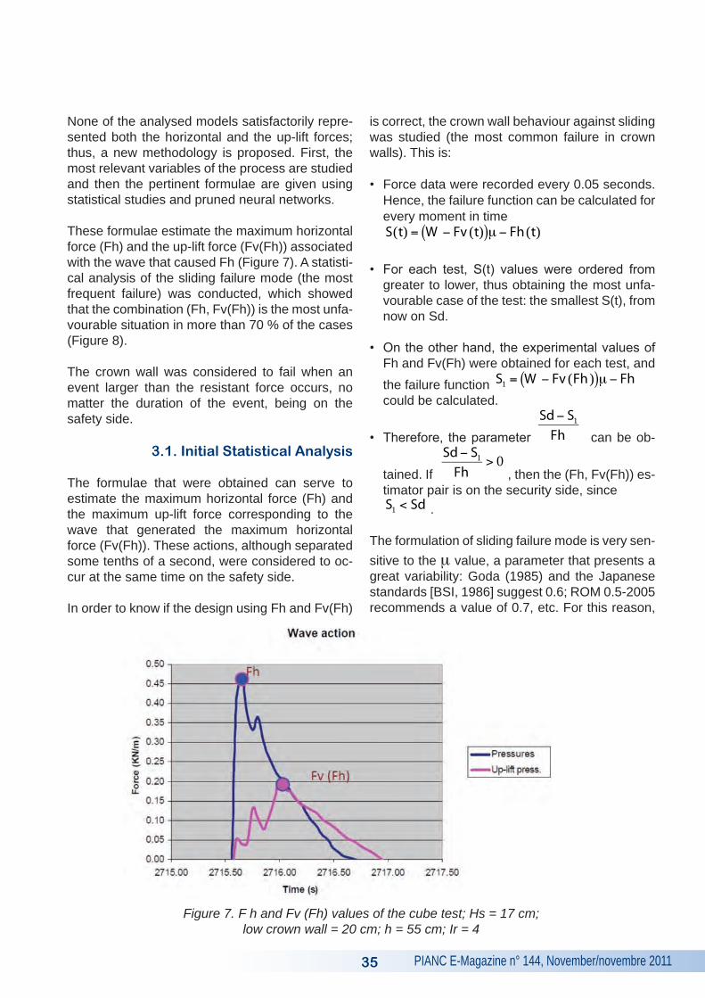
These formulae estimate the maximum horizontal force (Fh) and the up-lift force (Fv(Fh)) associated with the wave that caused Fh (Figure 7). A statisti-cal analysis of the sliding failure mode (the most frequent failure) was conducted, which showed that the combination (Fh, Fv(Fh)) is the most unfa-vourable situation in more than 70 % of the cases (Figure 8).
The crown wall was considered to fail when an event larger than the resistant force occurs, no matter the duration of the event, being on the safety side.
3.1. Initial Statistical Analysis
The formulae that were obtained can serve to estimate the maximum horizontal force (Fh) and the maximum up-lift force corresponding to the wave that generated the maximum horizontal force (Fv(Fh)). These actions, although separated some tenths of a second, were considered to oc-cur at the same time on the safety side.
In order to know if the design using Fh and Fv(Fh)
is correct, the crown wall behaviour against sliding was studied (the most common failure in crown walls). This is:
• Force data were recorded every 0.05 seconds. Hence, the failure function can be calculated for every moment in time
€
S(t) = W − Fv (t)( )m − Fh (t)
• For each test, S(t) values were ordered from greater to lower, thus obtaining the most unfa-vourable case of the test: the smallest S(t), from now on Sd.
• On the other hand, the experimental values of Fh and Fv(Fh) were obtained for each test, and the failure function
€
S1 = W − Fv (Fh )( )m − Fh could be calculated.
• Therefore, the parameter
€
Sd− S1
Fh can be ob-
tained. If
€
Sd− S1
Fh> 0
, then the (Fh, Fv(Fh)) es-timator pair is on the security side, since
€
S1 < Sd .
The formulation of sliding failure mode is very sen-sitive to the m value, a parameter that presents a great variability: Goda (1985) and the Japanese standards [BSI, 1986] suggest 0.6; ROM 0.5-2005 recommends a value of 0.7, etc. For this reason,
Figure 7. F h and Fv (Fh) values of the cube test; Hs = 17 cm; low crown wall = 20 cm; h = 55 cm; Ir = 4
PIANC E-Magazine n° 144, November/novembre 2011
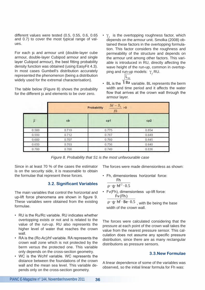
different values were tested (0.5, 0.55, 0.6, 0.65 and 0.7) to cover the most typical range of val-ues.
For each m and armour unit (double-layer cube armour, double-layer Cubipod armour and single layer Cubipod armour), the best fitting probability density function was obtained (using EasyFit 4.3). In most cases Gumbell’s distribution accurately represented the phenomenon (being a distribution widely used for the extremal characterisation).
The table below (Figure 8) shows the probability for the different m and elements to be over zero.
Since in at least 70 % of the cases the estimator is on the security side, it is reasonable to obtain the formulae that represent these forces.
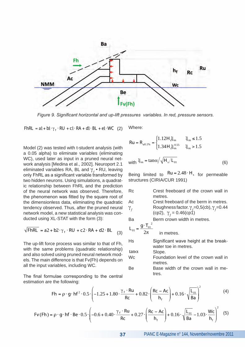
3.2. Significant Variables
The main variables that control the horizontal and up-lift force phenomena are shown in figure 9. These variables were obtained from the existing formulae.
• RU is the Ru/Rc variable. RU indicates whether overtopping exists or not and is related to the value of the run-up. RU also represents the higher level of water that reaches the crown wall.
• RA is the (Rc-Ac)/hf variable. RA represents the crown wall zone which is not protected by the berm versus the protected one. This variable only depends on the cross-section geometry.
• WC is the Wc/hf variable. WC represents the distance between the foundations of the crown wall and the mean sea level. This variable de-pends only on the cross-section geometry.
• gƒ is the overtopping roughness factor, which
depends on the armour unit. Smolka (2008) ob-tained these factors in the overtopping formula-tion. This factor considers the roughness and permeability of the structure and depends on the armour unit among other factors. This vari-able is introduced in RU, directly affecting the wave height of the run-up, common in overtop-ping and run-up models: g
ƒ RU.
• BL is the
€
L 01
Ba variable. BL represents the berm width and time period and it affects the water flow that arrives at the crown wall through the armour layer.
The forces were made dimensionless as shown:
• Fh, dimensionless horizontal force:
€
Fhρ ⋅ g⋅ hf 2 ⋅ 0.5
• Fv(Fh), dimensionless up-lift force:
€
Fv (Fh )ρ ⋅ g⋅ hf ⋅ Be ⋅ 0.5 , with Be being the base width of the crown wall.
The forces were calculated considering that the pressure at each point of the crown wall takes the value from the nearest pressure sensor. This cal-culation does not assume any specific pressure distribution, since there are as many rectangular distributions as pressure sensors.
3.3.New Formulae
A linear dependence of some of the variables was observed, so the initial linear formula for Fh was:
36
Figure 8. Probability that S1 is the most unfavourable case
PIANC E-Magazine n° 144, November/novembre 201137
€
FhRL = a1+ b1⋅ g f ⋅ RU + c1⋅ RA + d1⋅ BL + e1⋅WC (2)
Model (2) was tested with t-student analysis (with a 0.05 alpha) to eliminate variables (eliminating WC), used later as input in a pruned neural net-work analysis [Medina et al., 2002]. Neuroport 2.1 eliminated variables RA, BL and g
ƒ •
RU, leaving
only FhRL as a significant variable transformed by two hidden neurons. Using simulations, a quadrat-ic relationship between FhRL and the prediction of the neural network was observed. Therefore, the phenomenon was fitted by the square root of the dimensionless data, eliminating the quadratic tendency observed. Thus, after the pruned neural network model, a new statistical analysis was con-ducted using XL-STAT with the form (3):
€
FhRL = a2 + b2 ⋅ g f ⋅ RU + c2 ⋅ RA + d2 ⋅ BL (3)
The up-lift force process was similar to that of Fh, with the same problems (quadratic relationship) and also solved using pruned neural network mod-els. The main difference is that Fv(Fh) depends on all the input variables, including WC.
The final formulae corresponding to the central estimation are the following:
Where:
€
Ru = Ru0.1% =1.12Hsξm ξm ≤1.51.34Hsξm
0.55 ξm >1.5
⎧ ⎨ ⎩
with
€
ξm = tanα Hs L 01 (6)
Being limited to
€
Ru = 2.48 ⋅ Hs for permeable structures (CIRIA/CUR 1991)
Rc Crest freeboard of the crown wall in metres.
Ac Crest freeboard of the berm in metres.g
ƒ Roughness factor. g
ƒ=0,5(cb), g
ƒ=0.44
(cp2), gƒ = 0.46(cp1)
Ba Berm crown width in metres.
€
L 01 =g⋅ T01
2
2π in metres.
Hs Significant wave height at the break-water toe in metres.
€
tanα Slope.Wc Foundation level of the crown wall in
metres.Be Base width of the crown wall in me-
tres.
Figure 9. Significant horizontal and up-lift pressures variables. In red, pressure sensors.
€
Fv (Fh ) = ρ ⋅ g⋅ hf ⋅ Be ⋅ 0.5 ⋅ −0.6 + 0.40 ⋅g f ⋅ RuRc
+ 0.27 ⋅Rc − Ac
hf
⎛
⎝ ⎜ ⎜
⎞
⎠ ⎟ ⎟ + 0.16 ⋅
L 01
Ba−1.03 ⋅
Wchf
⎛
⎝ ⎜ ⎜
⎞
⎠ ⎟ ⎟
2
€
Fh = ρ ⋅ g⋅ hf 2 ⋅ 0.5 ⋅ −1.25 +1.80 ⋅g f ⋅ RuRc
+ 0.82 ⋅Rc − Ac
hf
⎛
⎝ ⎜ ⎜
⎞
⎠ ⎟ ⎟ + 0.16 ⋅
L 01
Ba
⎛
⎝ ⎜ ⎜
⎞
⎠ ⎟ ⎟
2
(4)
(5)
PIANC E-Magazine n° 144, November/novembre 2011 38
€
hf Crown wall height in metres.
Fh Maximum horizontal force in N/m.
Fv Maximum up-lift force associated with the wave that has generated the max-imum horizontal force in N/m.
€
ρ Water density in kg/m3.
g Gravity acceleration in m/s2.
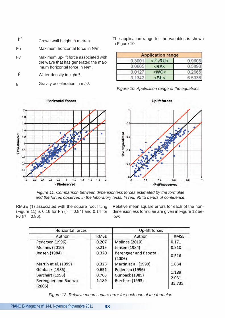
The application range for the variables is shown in Figure 10.
Figure 10. Application range of the equations
Figure 11. Comparison between dimensionless forces estimated by the formulae and the forces observed in the laboratory tests. In red, 95 % bands of confidence.
Figure 12. Relative mean square error for each one of the formulae
RMSE (1) associated with the square root fitting (Figure 11) is 0.16 for Fh (r2 = 0.84) and 0.14 for Fv (r2 = 0.86).
Relative mean square errors for each of the non-dimensionless formulae are given in Figure 12 be-low:
PIANC E-Magazine n° 144, November/novembre 201139
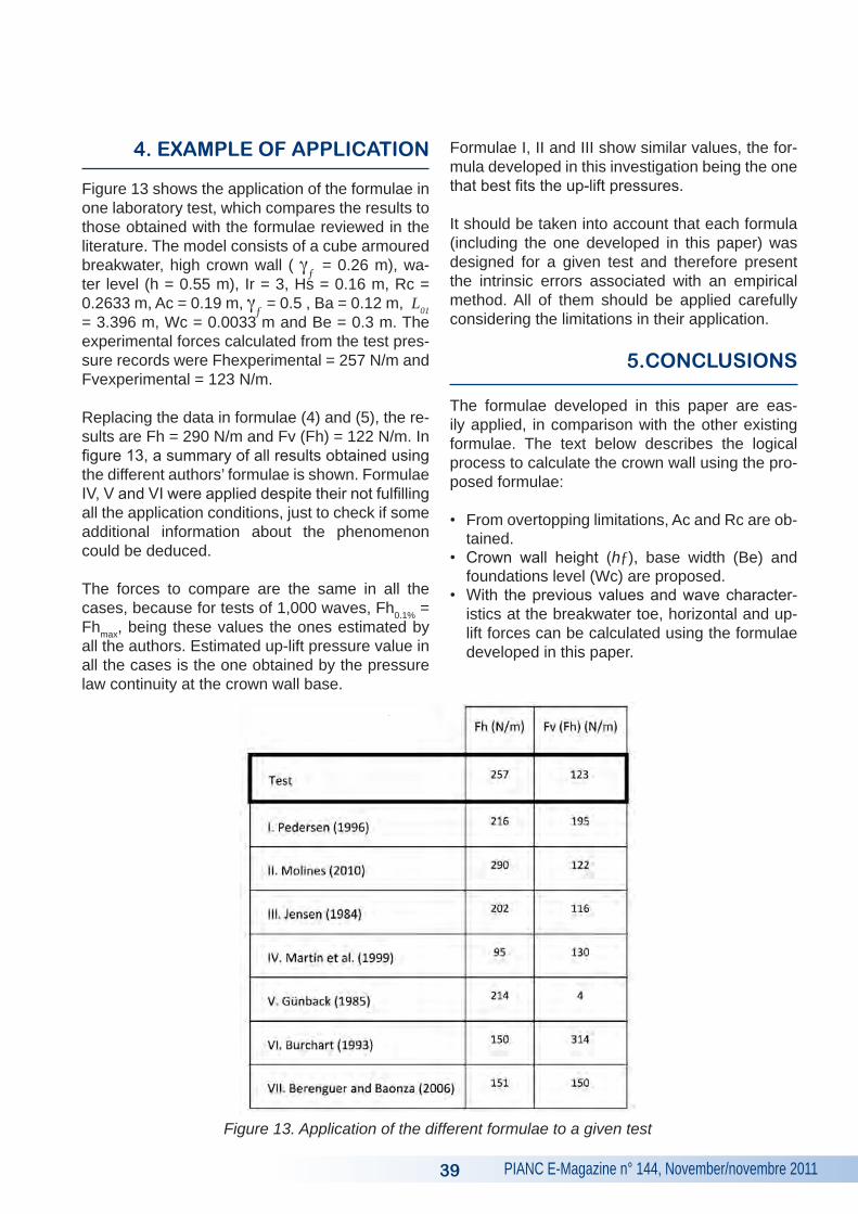
4. EXAMPLE OF APPLICATION
Figure 13 shows the application of the formulae in one laboratory test, which compares the results to those obtained with the formulae reviewed in the literature. The model consists of a cube armoured breakwater, high crown wall ( g
ƒ = 0.26 m), wa-
ter level (h = 0.55 m), Ir = 3, Hs = 0.16 m, Rc = 0.2633 m, Ac = 0.19 m, g
ƒ = 0.5 , Ba = 0.12 m, L01
= 3.396 m, Wc = 0.0033 m and Be = 0.3 m. The experimental forces calculated from the test pres-sure records were Fhexperimental = 257 N/m and Fvexperimental = 123 N/m.
Replacing the data in formulae (4) and (5), the re-sults are Fh = 290 N/m and Fv (Fh) = 122 N/m. In figure 13, a summary of all results obtained using the different authors’ formulae is shown. Formulae IV, V and VI were applied despite their not fulfilling all the application conditions, just to check if some additional information about the phenomenon could be deduced.
The forces to compare are the same in all the cases, because for tests of 1,000 waves, Fh0.1% = Fhmax, being these values the ones estimated by all the authors. Estimated up-lift pressure value in all the cases is the one obtained by the pressure law continuity at the crown wall base.
Formulae I, II and III show similar values, the for-mula developed in this investigation being the one that best fits the up-lift pressures.
It should be taken into account that each formula (including the one developed in this paper) was designed for a given test and therefore present the intrinsic errors associated with an empirical method. All of them should be applied carefully considering the limitations in their application.
5.CONCLUSIONS
The formulae developed in this paper are eas-ily applied, in comparison with the other existing formulae. The text below describes the logical process to calculate the crown wall using the pro-posed formulae:
• From overtopping limitations, Ac and Rc are ob-tained.
• Crown wall height (hƒ), base width (Be) and foundations level (Wc) are proposed.
• With the previous values and wave character-istics at the breakwater toe, horizontal and up-lift forces can be calculated using the formulae developed in this paper.
Figure 13. Application of the different formulae to a given test
PIANC E-Magazine n° 144, November/novembre 2011 40
• Active and passive earth pressure of the armour units adjacent to the crown wall should be cal-culated using the procedure presented in ROM 0.5-2005.
• Once the forces are calculated, the minimum weight of the crown wall can be obtained using ROM 0.5-2005, limiting the sliding security co-efficient to 1.5:
€
CSD =(Crown wall weight− ΣUp − lift forces)m
ΣHorizontal forces=1.5
(7)
• Once the minimum weight calculated, the crown wall must be checked to make sure it is possible to achieve this weight with the proposed base and height dimensions. If the minimum weight cannot be obtained, the calculation process should be repeated changing Be and hƒ val-ues.
Finally, the load transmitted from the crown wall to the foundations should be checked to make sure it does not surpass the bearing capacity obtained with Brinch Hansen’s formula (ROM 0.5-2005). Shear stress should not exceed material resis-tance in the concrete joint according to article 47.2 EHE (2008).
The new methodology presented in this paper is simple and was obtained using irregular labora-tory tests by means of linear regressions. There-fore, it is a robust method that considers the group waves effect.
Cube-Cubipod comparison shows that Cubipod ar-moured mound breakwaters present lower forces (and therefore a smaller crown wall size) than the cube armoured ones. The result is the lower cost of the Cubipod armoured breakwater because of the smaller amount of concrete used.
Future research will focus on the study of the cy-clical forces that affect the crown wall foundations as a consequence of the sine-crest wave action. This issue should be addressed through numeri-cal models that simulate the whole crown wall-soil system, using the necessary input parameters.
The obtained formulae allow for the complete characterisation of sliding failure, although the pressure distribution is not defined. The distribu-
tion most similar to our tests is that presented by Pedersen (1996) (Figure 3c). Although the critical type of failure is totally defined with Fh and Fv(Fh), it is interesting to define the pressure distribution to characterise the stability of the whole crown wall.
All the existing formulae (including the one de-veloped in this paper) should be applied carefully considering the limitations on their application.
Pressure distribution is currently one of our re-search topics, as well as the use of pruned neu-ral network models to improve crown wall design considering wave and geometric conditions.
6. REFERENCES
Berenguer, J.M. and Baonza, A. (2006): “Diseño del espaldón de los diques rompeolas”, Libro de ponencias del II Congreso Nacional de la Asocia-ción Técnica de Puertos y Costas, pp. 35-56 (in Spanish).
Bradbury, A.P., Allsop, N.W.H. and Stevens, R.V. (1988): “Hydraulic performance of breakwater crown walls”, Technical Report SR 146, Hydrau-lics research, Wallingford, UK.
British Standards Institution (1986): “BS 8004: Code of practice for foundations”, BSI, UK.
Bruun, P. (1985): “Design and Construction of Mounds for Breakwaters and Coastal Protection”, Elsevier Science Publishing Company Inc, Am-sterdam, The Netherlands.
Camus, P. and Flores, J. (2004): “Wave forces on crown walls: Evaluation of existing empirical for-mulae”, Proc. 29th ICCE, pp. 4087-4099.
CIRIA/CUR (1991): “Manual on the use of rock in coastal and shoreline engineering”, The Nether-lands. CUR, London, UK, CIRIA.
Corredor, A., Torres, R., Miñana, J.V., Fernán-dez, E., Menéndez, C.F., Santos, M., Gómez-Martín, M.E., Goumy, R. and Medina, J.R. (2008): “CUBÍPODO: Ensayos de estabilidad hidráulica 2D y 3D, estudio del remonte y rebase, diseño del encofrado y ensayos de caída de prototipos”,
PIANC E-Magazine n° 144, November/novembre 201141
Libro de ponencias del III Congreso Nacional de la Asociación Técnica de Puertos y Costas, pp. 187-211.
Figueres, M. and Medina, J.R. (2004): “Estimating incident and reflected waves using a fully nonlin-ear wave model”, Proc. 29th ICCE, pp. 594-603.
Goda, Y. (1985): “Random seas and design of maritime structures”, University of Tokyo Press.
Gómez-Martín, M.E. and Medina, J.R. (2007): “Cubipod concrete armor unit and heterogeneous packing”, Proc. Coastal Structures‘07, World Sci-entific Publishing, 140-151.
Günback, A.R. and Göcke, T. (1984): “Wave screen stability of rubble mound Breakwaters”, Int. Symposium of Maritime Structure in the Meditar-rean Sea, Athens, Greece, pp. 2099-2112.
Hamilton, D.G. and Hall, K.R. (1992): “Preliminary analysis of the stability of rubble mound break-water crown walls”, Proc. 23rd ICCE, pp. 1217-1230.
Jensen, O. J. (1984): “A monograph of rubble mound breakwaters”, Danish Hydraulic Institute, Hórsholm, Denmark.
Mansard, R. and Funke, E. (1980): “The Measure-ment of Incident and Reflected Spectra Using a Least Squares Method”, Proc.17th ICCE.
Martín, F.L., Vidal, C., Losada, M.A. and Medina, R. (1995): “Un método para el cálculo de las ac-ciones del oleaje sobre los espaldones de los diques rompeolas”, Ingeniería del agua, Vol. 2, Núm. 3, pp. 37-52.
Martín, F.L., Losada, M.A. and Medina, R. (1999): “Wave loads on rubble mound breakwater crown walls”, Coastal Engineering Vol. 37, pp. 149-174.
Medina, J.R., González-Escrivá, J.A., Garrido, J.M. and De Rouk, J. (2002): “Overtopping analy-sis using neural networks”, Proceedings ICCE 2002, ASCE, 2165-2177.
Pedersen, J. and Burchart, H.F. (1992): “Wave Forces on Crown Walls”, Proc. 23rd ICCE, pp. 1489-1502.
Pedersen, J. (1996): “Wave Forces and Over-topping on Crown Walls of Rubble Mound Brak-waters”, Series Paper 12/Hydraulic & Coastal Engineering Laboratory, Department of Civil Engi-neering, University of Aalborg, Denmark.
Puertos del Estado (2005): “Recomendaciones para Obras Marítimas”, ROM 0.5. “Recomen-daciones geotécnicas en el proyecto de Obras Marítimas y Portuarias”, Programa ROM. MOPU.
Silva, R., Govaere, G. and Martín, F. (1998): “A statistical tool for breakwater design”, Proc. 26th ICCE, pp. 1921-1933.
Smolka, E. (2008): “Estudio Experimental del Re-monte y Rebase de un dique en talud de Cubípo-dos: Aplicación al Nuevo Dique de Abrigo de Punta Langosteira (A Coruña)”, Proyecto Fin de Carrera de la ETSICCP de Valencia, Sep. 2008.
PIANC E-Magazine n° 144, November/novembre 2011 42
Mound breakwaters usually have concrete crown walls to reduce overtopping. The stability of the crown wall is necessary to develop the different operations involved in port activities, sliding be-ing the major failure mode. This paper focuses on sliding failure, using existing formulae to estimate wave forces on crown walls, e.g. Jensen (1984), Pedersen (1996), Martín et al. (1999), Berenguer and Baonza (2006), etc.
Physical model tests were carried out using two different armour units: cubic blocks and Cubipods. The model was attacked with regular and irregu-lar waves, measuring pressure values of the wave impacts. The analysed formulae do not accurately
represent the horizontal and up-lift forces at the same time, so a new method is proposed: esti-mating the maximum horizontal force and maxi-mum up-lift force associated with the wave that generated the largest horizontal force.
After defining the variables that influence the phe-nomenon, test data were treated with pruned neu-ral networks and statistical t-student analysis to obtain the new formulae to calculate the horizontal and up-lift forces. It was observed in the tests that these forces are most critical in more than 70 % of the cases. The main advantages of this method are simplicity and robustness, because the formu-lae were obtained applying linear regressions.
SUMMARY
Les digues à talus sont habituellement couron-nées de murs pour réduire les franchissements des vagues. Ces murs de couronnement sont nécessaires aux activités portuaires. Leur stabilité est importante : le principal mode de rupture étant le glissement. Cet article s’intéresse aux ruptures par glissement utilisant les formules d’estimation des efforts induits par les vagues sur les murs de couronnement - Jensen (1984), Pedersen (1996) et Martin et al. (1999), Berenguer et Baonza (2006), etc.
Des essais en modèles physiques réduits ont été conduits en utilisant deux types d’enrochements artificiels de carapace: blocs cubiques et Cubi-pods. Le modèle réduit a été soumis à des houles régulières et irrégulières. Les pressions d’impact des vagues ont été mesurées. Les formules analy-
sées ne représentent pas de façon suffisamment précises les forces horizontales et de sous pres-sions. Une nouvelle méthode est donc proposée en estimant la force horizontale maximale et la sous pression maximale associée à la vague qui génère la force horizontale maximale.
Après avoir défini les variables d’études, les don-nées expérimentales ont été traitées avec un réseau de neurones et une analyse statistique à l’aide de la loi de Student. Ce travail a permis d’obtenir de nouvelles formules pour calculer les efforts horizontaux et de sous pressions. Les es-sais ont montré que ces efforts étaient les plus cri-tiques dans plus de 70 % des cas. Les principaux avantages de cette méthode sont la simplicité et la robustesse car les formules sont obtenues par l’intermédiaire de régressions linéaires.
RéSUMé
PIANC E-Magazine n° 144, November/novembre 201143
Geschüttete Wellenbrecher haben in der Regel Kronen aus Beton, um den Wellenüberlauf zu verringern. Die Stabilität der Krone ist für die ver-schiedenen Betriebsarten bei Hafenaktivitäten notwendig, wobei das Abrutschen eine der häufig-sten Ursachen für Versagen ist. Der Schwerpunkt dieses Artikels liegt auf dem Abrutschen, wobei die bestehenden Formeln verwendet werden, um die auf die Krone einwirkenden Wellenkräfte abzuschätzen, z. B. Jensen (1984), Pedersen (1996), Martín et al. (1999), Berenguer and Ba-onza (2006), etc.
In physikalischen Modellen wurden Untersuchun-gen durchgeführt, wobei zwei verschiedene Deck-werksbefestigungen verwendet wurden: Kubische Blöcke und „Cubipods“. Das Modell wurde mit regelmäßigen und unregelmäßigen Wellen beauf-schlagt und die Druckwerte des Wellenschlags wurden gemessen. Die untersuchten Formeln geben nicht exakt die horizontalen Kräfte und die
Auftriebskräfte zur gleichen Zeit wieder, daher wird eine neue Methode vorgeschlagen: Die Ab-schätzung der höchsten horizontalen Kraft und der höchsten Auftriebskraft verbunden mit den Wellen, die die größte horizontale Kraft erzeu-gen.
Nachdem die Variabeln, die das Phänomen bee-influssen, definiert wurden, wurden die Untersu-chungsergebnisse mittels eines beschnittenen neuralen Netzwerks überprüft und eine statis-tische Student-t-Verteilungs-Analyse wurde du-rchgeführt, um neue Formeln zur Berechnung der horizontalen Kräfte und der Auftriebskräfte zu erh-alten. In den Untersuchungen wurde beobachtet, dass diese Kräfte in mehr als 70 % der Fälle sehr kritisch sind. Die Hauptvorteile dieser Methode sind ihre Einfachheit und Robustheit, weil diese Formeln durch Anwendung der linearen Regres-sion erstellt wurden.
ZUSAMMENFASSUNG

PIANC E-Magazine n° 144, November/novembre 2011 44

PIANC E-Magazine n° 144, November/novembre 201145
NEWS FROM THE NAVIGATION COMMUNITY
Discover the brand new PIANC blog which recently was created on the PIANC website! The blog can serve as a new discussion forum for all kinds of topics related to our Association. To visit the blog, please go to the PIANC homepage at http://www.pianc.org and click on ‘Blog’ in the menu on the left-hand side!
NEW: the PIANC blog!
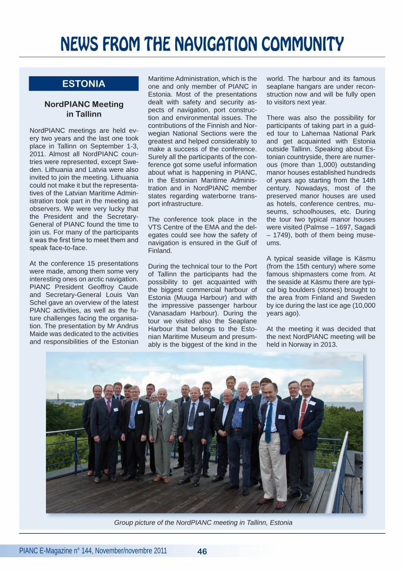
PIANC E-Magazine n° 144, November/novembre 2011
NEWS FROM THE NAVIGATION COMMUNITY
46
NordPIANC Meeting in Tallinn
NordPIANC meetings are held ev-ery two years and the last one took place in Tallinn on September 1-3, 2011. Almost all NordPIANC coun-tries were represented, except Swe-den. Lithuania and Latvia were also invited to join the meeting. Lithuania could not make it but the representa-tives of the Latvian Maritime Admin-istration took part in the meeting as observers. We were very lucky that the President and the Secretary-General of PIANC found the time to join us. For many of the participants it was the first time to meet them and speak face-to-face.
At the conference 15 presentations were made, among them some very interesting ones on arctic navigation. PIANC President Geoffroy Caude and Secretary-General Louis Van Schel gave an overview of the latest PIANC activities, as well as the fu-ture challenges facing the organisa-tion. The presentation by Mr Andrus Maide was dedicated to the activities and responsibilities of the Estonian
Maritime Administration, which is the one and only member of PIANC in Estonia. Most of the presentations dealt with safety and security as-pects of navigation, port construc-tion and environmental issues. The contributions of the Finnish and Nor-wegian National Sections were the greatest and helped considerably to make a success of the conference. Surely all the participants of the con-ference got some useful information about what is happening in PIANC, in the Estonian Maritime Adminis-tration and in NordPIANC member states regarding waterborne trans-port infrastructure.
The conference took place in the VTS Centre of the EMA and the del-egates could see how the safety of navigation is ensured in the Gulf of Finland.
During the technical tour to the Port of Tallinn the participants had the possibility to get acquainted with the biggest commercial harbour of Estonia (Muuga Harbour) and with the impressive passenger harbour (Vanasadam Harbour). During the tour we visited also the Seaplane Harbour that belongs to the Esto-nian Maritime Museum and presum-ably is the biggest of the kind in the
world. The harbour and its famous seaplane hangars are under recon-struction now and will be fully open to visitors next year.
There was also the possibility for participants of taking part in a guid-ed tour to Lahemaa National Park and get acquainted with Estonia outside Tallinn. Speaking about Es-tonian countryside, there are numer-ous (more than 1,000) outstanding manor houses established hundreds of years ago starting from the 14th century. Nowadays, most of the preserved manor houses are used as hotels, conference centres, mu-seums, schoolhouses, etc. During the tour two typical manor houses were visited (Palmse – 1697, Sagadi – 1749), both of them being muse-ums.
A typical seaside village is Käsmu (from the 15th century) where some famous shipmasters come from. At the seaside at Käsmu there are typi-cal big boulders (stones) brought to the area from Finland and Sweden by ice during the last ice age (10,000 years ago).
At the meeting it was decided that the next NordPIANC meeting will be held in Norway in 2013.
ESTONIA
Group picture of the NordPIANC meeting in Tallinn, Estonia
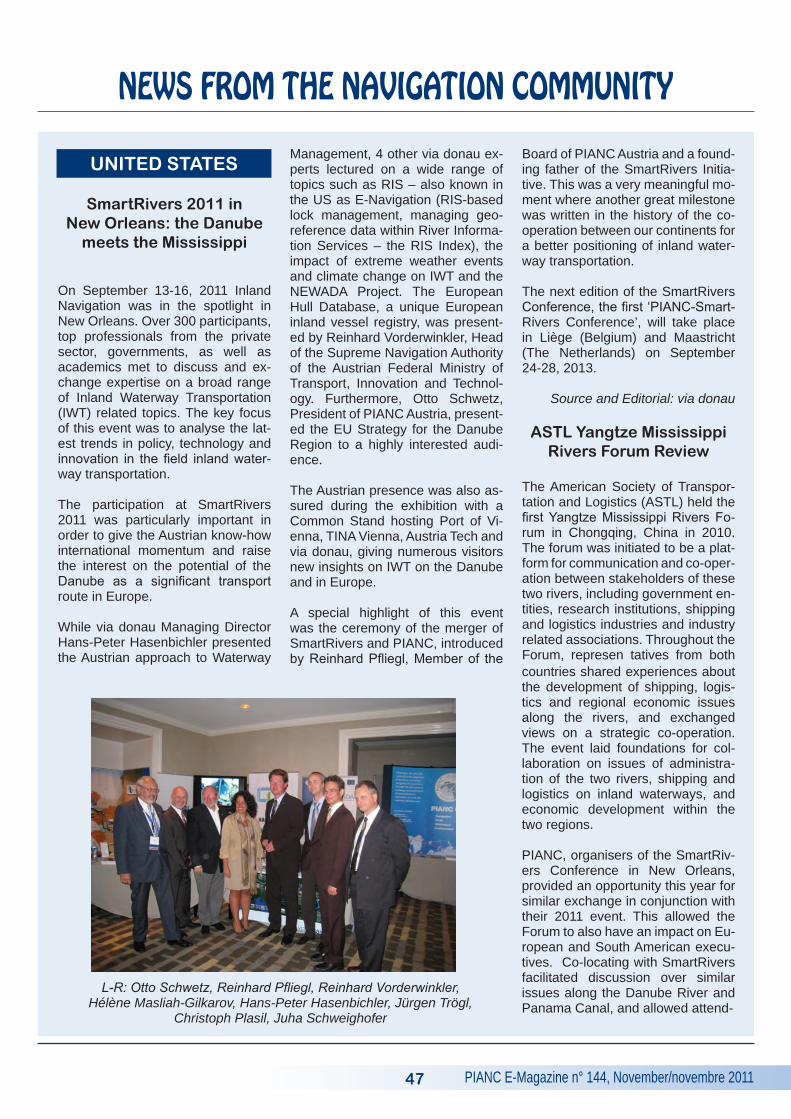
PIANC E-Magazine n° 144, November/novembre 2011
SmartRivers 2011 in New Orleans: the Danube
meets the Mississippi
On September 13-16, 2011 Inland Navigation was in the spotlight in New Orleans. Over 300 participants, top professionals from the private sector, governments, as well as academics met to discuss and ex-change expertise on a broad range of Inland Waterway Transportation (IWT) related topics. The key focus of this event was to analyse the lat-est trends in policy, technology and innovation in the field inland water-way transportation.
The participation at SmartRivers 2011 was particularly important in order to give the Austrian know-how international momentum and raise the interest on the potential of the Danube as a significant transport route in Europe.
While via donau Managing Director Hans-Peter Hasenbichler presented the Austrian approach to Waterway
Management, 4 other via donau ex-perts lectured on a wide range of topics such as RIS – also known in the US as E-Navigation (RIS-based lock management, managing geo-reference data within River Informa-tion Services – the RIS Index), the impact of extreme weather events and climate change on IWT and the NEWADA Project. The European Hull Database, a unique European inland vessel registry, was present-ed by Reinhard Vorderwinkler, Head of the Supreme Navigation Authority of the Austrian Federal Ministry of Transport, Innovation and Technol-ogy. Furthermore, Otto Schwetz, President of PIANC Austria, present-ed the EU Strategy for the Danube Region to a highly interested audi-ence.
The Austrian presence was also as-sured during the exhibition with a Common Stand hosting Port of Vi-enna, TINA Vienna, Austria Tech and via donau, giving numerous visitors new insights on IWT on the Danube and in Europe.
A special highlight of this event was the ceremony of the merger of SmartRivers and PIANC, introduced by Reinhard Pfliegl, Member of the
Board of PIANC Austria and a found-ing father of the SmartRivers Initia-tive. This was a very meaningful mo-ment where another great milestone was written in the history of the co-operation between our continents for a better positioning of inland water-way transportation.
The next edition of the SmartRivers Conference, the first ‘PIANC-Smart-Rivers Conference’, will take place in Liège (Belgium) and Maastricht (The Netherlands) on September 24-28, 2013.
Source and Editorial: via donau
ASTL Yangtze Mississippi Rivers Forum Review
The American Society of Transpor-tation and Logistics (ASTL) held the first Yangtze Mississippi Rivers Fo-rum in Chongqing, China in 2010. The forum was initiated to be a plat-form for communication and co-oper-ation between stakeholders of these two rivers, including government en-tities, research institutions, shipping and logistics industries and industry related associations. Throughout the Forum, represen tatives from both
UNITED STATES
47
NEWS FROM THE NAVIGATION COMMUNITY
L-R: Otto Schwetz, Reinhard Pfliegl, Reinhard Vorderwinkler, Hélène Masliah-Gilkarov, Hans-Peter Hasenbichler, Jürgen Trögl,
Christoph Plasil, Juha Schweighofer
countries shared experiences about the development of shipping, logis-tics and regional economic issues along the rivers, and exchanged views on a strategic co-operation. The event laid foundations for col-laboration on issues of administra-tion of the two rivers, shipping and logistics on inland waterways, and economic development within the two regions.
PIANC, organisers of the SmartRiv-ers Conference in New Orleans, provided an opportunity this year for similar exchange in conjunction with their 2011 event. This allowed the Forum to also have an impact on Eu-ropean and South American execu-tives. Co-locating with SmartRivers facilitated discussion over similar issues along the Danube River and Panama Canal, and allowed attend-
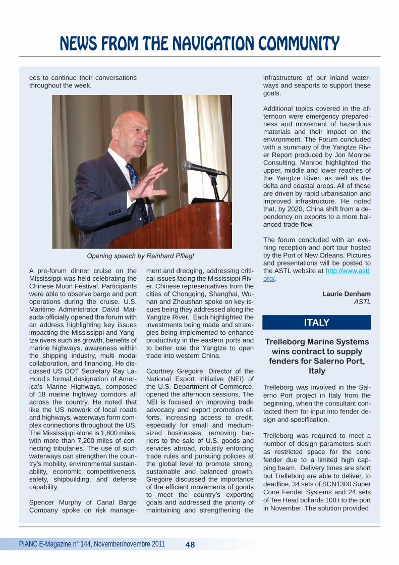
PIANC E-Magazine n° 144, November/novembre 2011
NEWS FROM THE NAVIGATION COMMUNITY
ees to continue their conversations throughout the week.
A pre-forum dinner cruise on the Mississippi was held celebrating the Chinese Moon Festival. Participants were able to observe barge and port operations during the cruise. U.S. Maritime Administrator David Mat-suda officially opened the forum with an address highlighting key issues impacting the Mississippi and Yang-tze rivers such as growth, benefits of marine highways, awareness within the shipping industry, multi modal collaboration, and financing. He dis-cussed US DOT Secretary Ray La-Hood’s formal designation of Amer-ica’s Marine Highways, composed of 18 marine highway corridors all across the country. He noted that like the US network of local roads and highways, waterways form com-plex connections throughout the US. The Mississippi alone is 1,800 miles, with more than 7,200 miles of con-necting tributaries. The use of such waterways can strengthen the coun-try’s mobility, environmental sustain-ability, economic competitiveness, safety, shipbuilding, and defense capability.
Spencer Murphy of Canal Barge Company spoke on risk manage-
ment and dredging, addressing criti-cal issues facing the Mississippi Riv-er. Chinese representatives from the cities of Chongqing, Shanghai, Wu-han and Zhoushan spoke on key is-sues being they addressed along the Yangtze River. Each highlighted the investments being made and strate-gies being implemented to enhance productivity in the eastern ports and to better use the Yangtze to open trade into western China.
Courtney Gregoire, Director of the National Export Initiative (NEI) of the U.S. Department of Commerce, opened the afternoon sessions. The NEI is focused on improving trade advocacy and export promotion ef-forts, increasing access to credit, especially for small and medium-sized businesses, removing bar-riers to the sale of U.S. goods and services abroad, robustly enforcing trade rules and pursuing policies at the global level to promote strong, sustainable and balanced growth. Gregoire discussed the importance of the efficient movements of goods to meet the country’s exporting goals and addressed the priority of maintaining and strengthening the
infrastructure of our inland water-ways and seaports to support these goals.
Additional topics covered in the af-ternoon were emergency prepared-ness and movement of hazardous materials and their impact on the environment. The Forum concluded with a summary of the Yangtze Riv-er Report produced by Jon Monroe Consulting. Monroe highlighted the upper, middle and lower reaches of the Yangtze River, as well as the delta and coastal areas. All of these are driven by rapid urbanisation and improved infrastructure. He noted that, by 2020, China shift from a de-pendency on exports to a more bal-anced trade flow.
The forum concluded with an eve-ning reception and port tour hosted by the Port of New Orleans. Pictures and presentations will be posted to the ASTL website at http://www.astl.org/.
Laurie DenhamASTL
Trelleborg Marine Systems wins contract to supply
fenders for Salerno Port, Italy
Trelleborg was involved in the Sal-erno Port project in Italy from the beginning, when the consultant con-tacted them for input into fender de-sign and specification.
Trelleborg was required to meet a number of design parameters such as restricted space for the cone fender due to a limited high cap-ping beam. Delivery times are short but Trelleborg are able to deliver, to deadline, 34 sets of SCN1300 Super Cone Fender Systems and 24 sets of Tee Head bollards 100 t to the port in November. The solution provided
48
Opening speech by Reinhard Pfliegl
ITALY
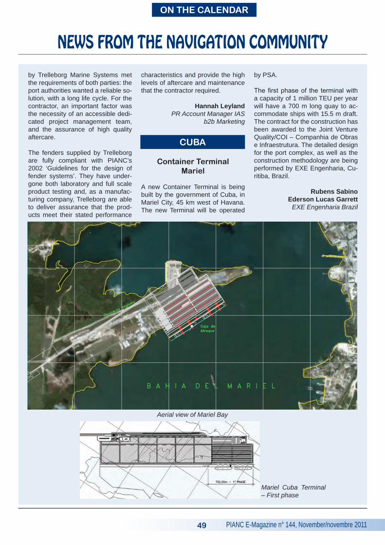
PIANC E-Magazine n° 144, November/novembre 2011
NEWS FROM THE NAVIGATION COMMUNITY
by Trelleborg Marine Systems met the requirements of both parties: the port authorities wanted a reliable so-lution, with a long life cycle. For the contractor, an important factor was the necessity of an accessible dedi-cated project management team, and the assurance of high quality aftercare.
The fenders supplied by Trelleborg are fully compliant with PIANC’s 2002 ‘Guidelines for the design of fender systems’. They have under-gone both laboratory and full scale product testing and, as a manufac-turing company, Trelleborg are able to deliver assurance that the prod-ucts meet their stated performance
characteristics and provide the high levels of aftercare and maintenance that the contractor required.
Hannah LeylandPR Account Manager IAS
b2b Marketing
Container Terminal Mariel
A new Container Terminal is being built by the government of Cuba, in Mariel City, 45 km west of Havana. The new Terminal will be operated
by PSA.
The first phase of the terminal with a capacity of 1 million TEU per year will have a 700 m long quay to ac-commodate ships with 15.5 m draft. The contract for the construction has been awarded to the Joint Venture Quality/COI – Companhia de Obras e Infraestrutura. The detailed design for the port complex, as well as the construction methodology are being performed by EXE Engenharia, Cu-ritiba, Brazil.
Rubens SabinoEderson Lucas Garrett
EXE Engenharia Brazil
49
ON ThE CALENDAR
CUBA
Aerial view of Mariel Bay
Mariel Cuba Terminal – First phase
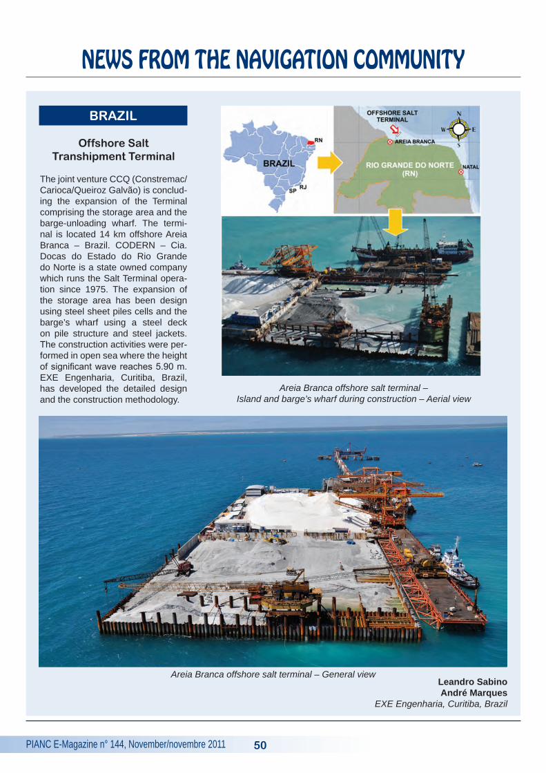
PIANC E-Magazine n° 144, November/novembre 2011
NEWS FROM THE NAVIGATION COMMUNITY
Offshore Salt Transhipment Terminal
The joint venture CCQ (Constremac/Carioca/Queiroz Galvão) is conclud-ing the expansion of the Terminal comprising the storage area and the barge-unloading wharf. The termi-nal is located 14 km offshore Areia Branca – Brazil. CODERN – Cia. Docas do Estado do Rio Grande do Norte is a state owned company which runs the Salt Terminal opera-tion since 1975. The expansion of the storage area has been design using steel sheet piles cells and the barge’s wharf using a steel deck on pile structure and steel jackets. The construction activities were per-formed in open sea where the height of significant wave reaches 5.90 m. EXE Engenharia, Curitiba, Brazil, has developed the detailed design and the construction methodology.
Leandro SabinoAndré Marques
EXE Engenharia, Curitiba, Brazil
50
BRAZIL
Areia Branca offshore salt terminal – General view
Areia Branca offshore salt terminal – Island and barge’s wharf during construction – Aerial view
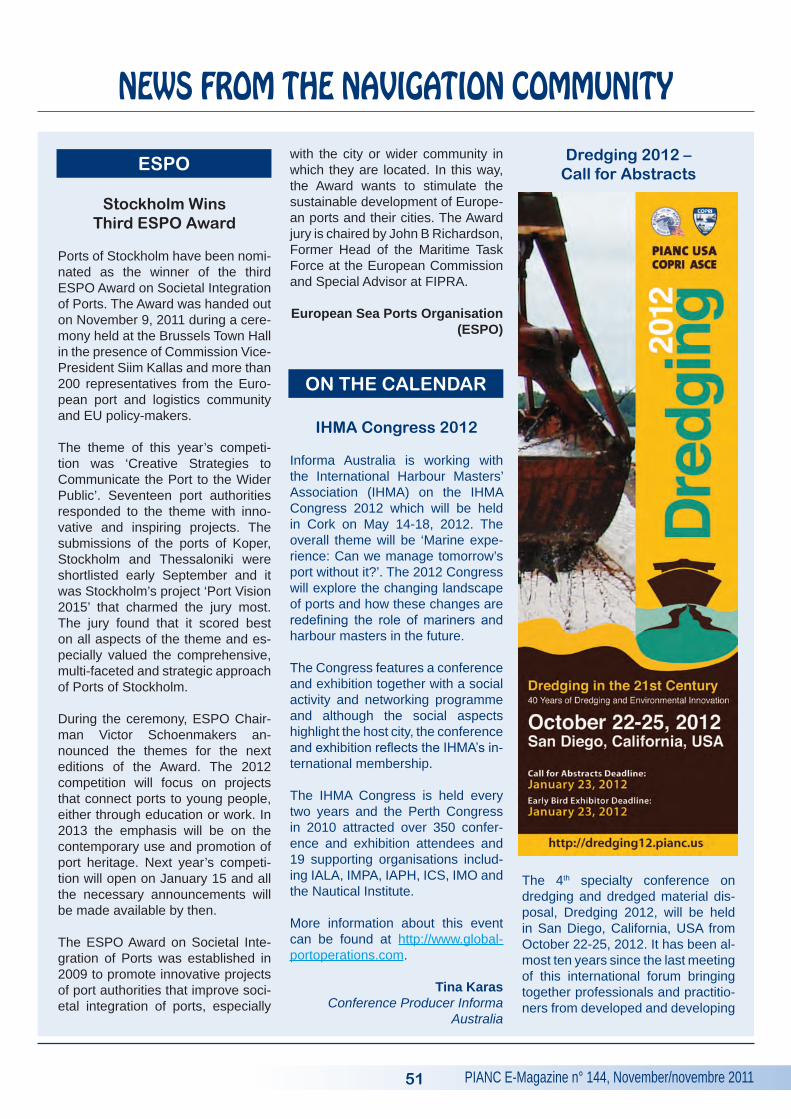
PIANC E-Magazine n° 144, November/novembre 2011
NEWS FROM THE NAVIGATION COMMUNITY
Stockholm Wins Third ESPO Award
Ports of Stockholm have been nomi-nated as the winner of the third ESPO Award on Societal Integration of Ports. The Award was handed out on November 9, 2011 during a cere-mony held at the Brussels Town Hall in the presence of Commission Vice-President Siim Kallas and more than 200 representatives from the Euro-pean port and logistics community and EU policy-makers.
The theme of this year’s competi-tion was ‘Creative Strategies to Communicate the Port to the Wider Public’. Seventeen port authorities responded to the theme with inno-vative and inspiring projects. The submissions of the ports of Koper, Stockholm and Thessaloniki were shortlisted early September and it was Stockholm’s project ‘Port Vision 2015’ that charmed the jury most. The jury found that it scored best on all aspects of the theme and es-pecially valued the comprehensive, multi-faceted and strategic approach of Ports of Stockholm.
During the ceremony, ESPO Chair-man Victor Schoenmakers an-nounced the themes for the next editions of the Award. The 2012 competition will focus on projects that connect ports to young people, either through education or work. In 2013 the emphasis will be on the contemporary use and promotion of port heritage. Next year’s competi-tion will open on January 15 and all the necessary announcements will be made available by then.
The ESPO Award on Societal Inte-gration of Ports was established in 2009 to promote innovative projects of port authorities that improve soci-etal integration of ports, especially
with the city or wider community in which they are located. In this way, the Award wants to stimulate the sustainable development of Europe-an ports and their cities. The Award jury is chaired by John B Richardson, Former Head of the Maritime Task Force at the European Commission and Special Advisor at FIPRA.
European Sea Ports Organisation (ESPO)
IhMA Congress 2012
Informa Australia is working with the International Harbour Masters’ Association (IHMA) on the IHMA Congress 2012 which will be held in Cork on May 14-18, 2012. The overall theme will be ‘Marine expe-rience: Can we manage tomorrow’s port without it?’. The 2012 Congress will explore the changing landscape of ports and how these changes are redefining the role of mariners and harbour masters in the future.
The Congress features a conference and exhibition together with a social activity and networking programme and although the social aspects highlight the host city, the conference and exhibition reflects the IHMA’s in-ternational membership. The IHMA Congress is held every two years and the Perth Congress in 2010 attracted over 350 confer-ence and exhibition attendees and 19 supporting organisations includ-ing IALA, IMPA, IAPH, ICS, IMO and the Nautical Institute.
More information about this event can be found at http://www.global-portoperations.com.
Tina KarasConference Producer Informa
Australia
Dredging 2012 – Call for Abstracts
The 4th specialty conference on dredging and dredged material dis-posal, Dredging 2012, will be held in San Diego, California, USA from October 22-25, 2012. It has been al-most ten years since the last meeting of this international forum bringing together professionals and practitio-ners from developed and developing
51
ESPO
ON ThE CALENDAR
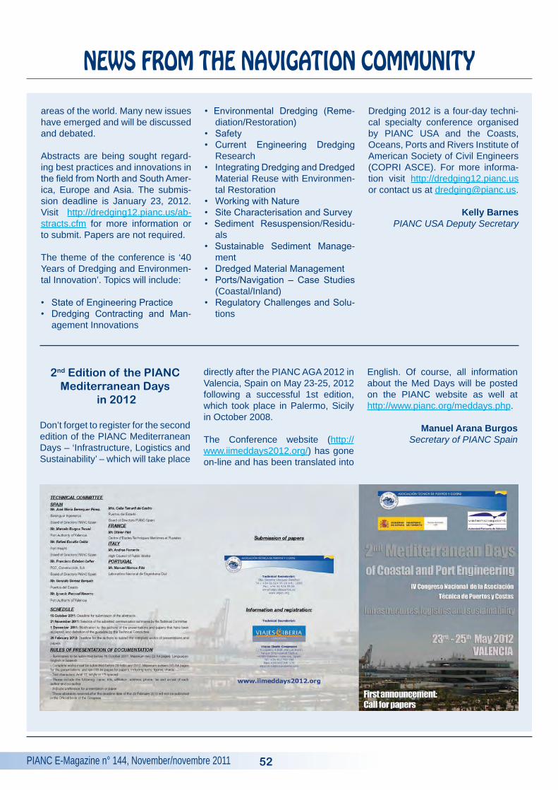
PIANC E-Magazine n° 144, November/novembre 2011
NEWS FROM THE NAVIGATION COMMUNITY
areas of the world. Many new issues have emerged and will be discussed and debated. Abstracts are being sought regard-ing best practices and innovations in the field from North and South Amer-ica, Europe and Asia. The submis-sion deadline is January 23, 2012. Visit http://dredging12.pianc.us/ab-stracts.cfm for more information or to submit. Papers are not required. The theme of the conference is ‘40 Years of Dredging and Environmen-tal Innovation’. Topics will include:
• State of Engineering Practice• Dredging Contracting and Man-
agement Innovations
• Environmental Dredging (Reme-diation/Restoration)
• Safety• Current Engineering Dredging
Research• Integrating Dredging and Dredged
Material Reuse with Environmen-tal Restoration
• Working with Nature• Site Characterisation and Survey• Sediment Resuspension/Residu-
als• Sustainable Sediment Manage-
ment• Dredged Material Management• Ports/Navigation – Case Studies
(Coastal/Inland)• Regulatory Challenges and Solu-
tions
Dredging 2012 is a four-day techni-cal specialty conference organised by PIANC USA and the Coasts, Oceans, Ports and Rivers Institute of American Society of Civil Engineers (COPRI ASCE). For more informa-tion visit http://dredging12.pianc.us or contact us at [email protected].
Kelly BarnesPIANC USA Deputy Secretary
52
2nd Edition of the PIANC Mediterranean Days
in 2012
Don’t forget to register for the second edition of the PIANC Mediterranean Days – ‘Infrastructure, Logistics and Sustainability’ – which will take place
directly after the PIANC AGA 2012 in Valencia, Spain on May 23-25, 2012 following a successful 1st edition, which took place in Palermo, Sicily in October 2008.
The Conference website (http://www.iimeddays2012.org/) has gone on-line and has been translated into
English. Of course, all information about the Med Days will be posted on the PIANC website as well at http://www.pianc.org/meddays.php.
Manuel Arana BurgosSecretary of PIANC Spain
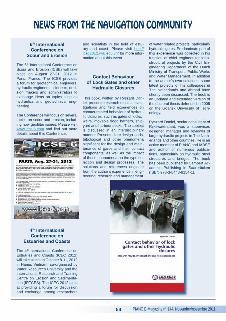
PIANC E-Magazine n° 144, November/novembre 2011
NEWS FROM THE NAVIGATION COMMUNITY
6th International Conference on
Scour and Erosion
The 6th International Conference on Scour and Erosion (ICSE) will take place on August 27-31, 2012 in Paris, France. The ICSE provides a forum for geotechnical engineers, hydraulic engineers, scientists, deci-sion makers and administrators to exchange ideas on topics such as hydraulics and geotechnical engi-neering.
The Conference will focus on several topics on scour and erosion, includ-ing now geofilter issues. Please visit www.icse-6.com and find out more details about this Conference.
4th International Conference on
Estuaries and Coasts
The 4th International Conference on Estuaries and Coasts (ICEC 2012) will take place on October 8-11, 2012 in Hanoi, Vietnam, co-organised by Water Resources University and the International Research and Training Centre on Erosion and Sedimenta-tion (IRTCES). The ICEC 2012 aims at providing a forum for discussion and exchange among researchers
and scientists in the field of estu-ary and coast. Please visit http://icec2012.wru.edu.vn/ for more infor-mation about this event.
Contact Behaviour of Lock Gates and other
hydraulic Closures
This book, written by Ryszard Dan-iel, presents research results, inves-tigations and field experiences on contact-related behaviour of hydrau-lic closures, such as gates of locks, weirs, movable flood barriers, ship-yard and harbour docks. The subject is discussed in an interdisciplinary manner. Presented are design loads, tribological and other phenomena significant for the design and main-tenance of gares and their contact components, as well as the impact of those phenomena on the type se-lection and design processes. The solutions and references originate from the author’s experience in engi-neering, research and management
of water related projects, particularly hydraulic gates. Predominate part of this experience was collected in his function of chief engineer for infra-structural projects by the Civil En-gineering Department of the Dutch Ministry of Transport, Public Works and Water Management. In addition to the author’s own solutions, some latest projects of his colleagues in The Netherlands and abroad have shortly been discussed. The book is an updated and extended version of the doctoral thesis defended in 2005 on the Gdansk University of Tech-nology.
Ryszard Daniel, senior consultant of Rijkswaterstaat, was a supervisor, designer, manager and reviewer of large hydraulic projects in The Neth-erlands and other countries. He is an active member of PIANC and IABSE and author of numerous publica-tions, particularly on hydraulic steel structures and bridges. The book has been published by Lambert Ac-ademic Publishing in Saarbrücken (ISBN 978-3-8443-9154-1).
53

PIANC E-Magazine n° 144, November/novembre 2011
PIANC General SecretariatBoulevard du Roi Albert II 20, B 3B-1000 BruxellesBelgique
http://www.pianc.orgVAT BE 408-287-945