The Westerly Storage Tunnel and Dewatering Pump Station · The Westerly Storage Tunnel and...
31
The Westerly Storage Tunnel and Dewatering Pump Station: How to Hit a Moving Target June 28, 2017
Transcript of The Westerly Storage Tunnel and Dewatering Pump Station · The Westerly Storage Tunnel and...

The Westerly Storage Tunnel and Dewatering Pump Station:How to Hit a Moving TargetJune 28, 2017

NEORSD Introduction
2
• 355 square mile service area• 61 member communities

Presentation Outline
3Image via Jim Dubelko, “Where in the World is Walworth Run?,” Cleveland Historical, accessed June 12, 2017, https://clevelandhistorical.org/items/show/659.
• Walworth Run’s History
• Westerly Storage Tunnel & Dewatering Pump Station: project background and prior studies
• Design-phase flow monitoring
• H+H model recalibration
• Resulting adjustments to tunnel and pump station designs

Project History: Walworth Run (main CSO location)
4Image via Jim Dubelko, “Where in the World is Walworth Run?,” Cleveland Historical, accessed June 12, 2017, https://clevelandhistorical.org/items/show/659.
0.25 mi to Lake Erie

Industrialization along Walworth Run
5Image via Jim Dubelko, “Where in the World is Walworth Run?,” Cleveland Historical, accessed June 12, 2017, https://clevelandhistorical.org/items/show/659.
Lake Erie

Flooding and Pollution Problems
6
While normally a small and slow-moving stream, Walworth
Run would flood quickly in storms even during the 1850s.
Public outrage over the use of Walworth Run as an open sewer grew with the industrialization of the area, peaking during the
1870s and 1880s
Images and historical information via Jim Dubelko, “Where in the World is Walworth Run?,” Cleveland Historical, accessed June 12, 2017, https://clevelandhistorical.org/items/show/659.

Construction of Walworth Run Sewer
7
Construction of Walworth Run, 1897
Image via Jim Dubelko, “Where in the World is Walworth Run?,” Cleveland Historical, accessed June 12, 2017, https://clevelandhistorical.org/items/show/659.

Outlet of Walworth Run: 1905 (A.K.A. CSO-080)
8Image via Jim Dubelko, “Where in the World is Walworth Run?,” Cleveland Historical, accessed June 12, 2017, https://clevelandhistorical.org/items/show/659.

Site Conditions at CSO-080: Present Day
9
LAKE ERIE, 1 MI NORTHWEST
(DOWNSTREAM)

Combined Sewer Overflows at CSO-080
• Approximately 300 MG of CSO enters the Cuyahoga River from CSO-080 in a Typical Year of Rainfall (TY)
• ~50 activations per TY• Consent Decree requires reduction to 2 activations/TY• The Westerly Storage Tunnel (WST) would provide an
expected CSO volume reduction to 72 MG/TY in a 2010 estimate
10
Presenter
Presentation Notes
300 MG = 750 FT DEEP FOOTBALL FIELD

Reducing CSO Volumes:Tunnel Alignment and Profile Overview
11
WST-1: Westerly Tunnel
Dewatering Pump Station WST-2 Diversion
Structure
WST-3 Diversion Structure
Westerly WWTC
CWD Morgan
WTP
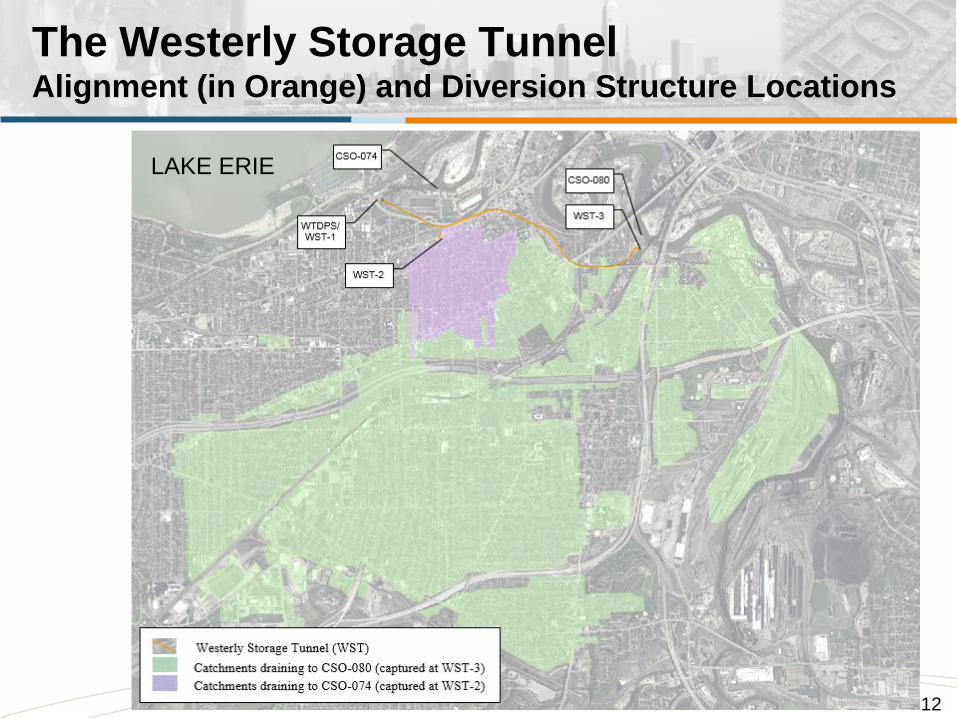
The Westerly Storage TunnelAlignment (in Orange) and Diversion Structure Locations
12
LAKE ERIE

Capture Areas (shown in green and pink)
13
LAKE ERIE

Original Hydraulic Model Calibration (1997):Red Squares show Flow Meter Locations
14

Exclusion of Several Phase II Meters
15
From Westerly Phase II Facilities Report, 1997

Original Hydraulic Model Calibration (Overlay):Solid areas were accurately calibrated & verified in Phase II Facilities Plan
16

Flow Monitoring Locations (in red)
17

Flow Meter Sub-basins
18

Recalibration of Hydraulic Model (Overlay):Transparent areas (pink and green) recalibrated per 2016 flow monitoring
19

Rainfall Data from NEORSD Gages
20

Flow Monitoring Results
21
Rainfall Model Meter
Early monitored events suggest that the model is overpredicting, but more data must be collected before recalibration can finally be accurately performed, during 60% design of WST/WTDPS

Original Model Calibration Results:36 MG Tunnel Controls to 2 CSO Activations/TY
22
Tunnel volume set at 36 MG based on original
model calibration

Model Recalibration Results:36 MG Tunnel is Oversized
23
Recalibrated model would have sized
the tunnel at 25 MG
*data per 6/20/2017 calibration
25 M
G36.5
MG
37 M
G

Implications for Design Post-Recalibration
• During the 60% design stage, NEORSD and the Stantec/MM Joint Venture review the best available options to take advantage of the recalibration results.
• The Consent Decree requires a 36 MG tunnel to be built, but the connecting structures can be resized as needed so long as the performance requirement (≤2 activations/TY) is achieved
• So…– EITHER design features can be downsized– OR the tunnel’s connecting structures can be left oversized
and thereby capable of exceeding the requirements of the Consent Decree
24

• WTDPS:– Surge risk mitigated by lower-than-expected flows
25
Design Implications – Pump Station (WTDPS)

26
• Validation of an earlier proposal to remove the dedicated overflow conduit proposed in planning-stage design
• Elimination of 1,100 linear feet of 8’x20’ box culvert
WTDPS

Design Implications – WST-2
27
• WST-2:• Baffle drop structure shaft diameter is reduced from 18’ to 12’• Depth of diversion structure’s grit sump is reduced by 4 feet• Connecting sewer sizes reduced from 60” to 48”

Design Implications – WST-3
• WST-3:– Baffle drop structure shaft diameter is reduced from 50’ to 40’– Twin 7’x10’ hydraulic gates become twin 7’x6’ gates– Depth of diversion structure’s grit sump is reduced by 5 feet
28
Modeled 16.5 foot sewer
Modeled WST-3 Diversion Structure
Sump becomes 5 feet shallower
Drop structure shaft diameter decreases by
10 ft
Presenter
Presentation Notes
3D model?

Implications for Consent Decree Targets
• 0 overflows now predicted at WST-2 (3 allowed per CD)• 1 overflows per year predicted at WST-3 (2 allowed per CD)
29
*data per 6/20/2017 calibration
36 MG Tunnel Storage

Implications for Consent Decree Targets, continued
Overflow volumes reduced relative to CD Targets– 72 MG of CSO proposed in 2010 per original model– 43 MG of CSO expected post-AFP (shown in grey)– 11.3 MG CSO predicted per recalibrated model (shown in blue)
30
*data per 6/20/2017 calibration

QUESTIONS?
Image via Jim Dubelko, “Where in the World is Walworth Run?,” Cleveland Historical, accessed June 12, 2017, https://clevelandhistorical.org/items/show/659.
“Industry and Nature in Harmony”: Artist’s depiction of Walworth Run near the confluence with the Cuyahoga River, 1874
31