The United States Air Force Flight Test Center Experiment ... Meeting Proceedings/RTO... · The...
20
RTO-MP-SCI-162 21 - 1 The United States Air Force Flight Test Center Experiment in Experimental Design George Kailiwai III Air Force Flight Test Center Technical Advisor (AFFTC/CT) 1 South Rosamond Boulevard Edwards Air Force Base, California 93524-1031 USA [email protected] ABSTRACT Keeping true to US Air Force Flight Test Center (AFFTC) motto of “Toward the Unexplored” and mission of conducting and supporting the research, development, test and evaluation of aerospace systems from concept to combat, senior AFFTC technical leaders are conducting an experiment on the applicability of design of experiments (DOE) as a possible test strategy for developmental test and evaluation (DT&E) flight test programs. To this end, AFFTC engineers have completed DOE orientation courses and a three-week course in basic statistics and DOE. The AFFTC then identified specific engineer technical experts as members of the AFFTC initial DOE cadre. Members of this initial cadre have implemented DOE as a test strategy to three USAF Test Pilot School (TPS) Test Management Projects (TMPs). Although these TMPs are still on-going, preliminary results show strong applicability to two of the three TMPs—Project HAVE NOT and Project START. The third TMP, Project LOST WINGMAN, is a classical DT&E flight test program with a gradual build-up approach in which the test team has chosen to use One Factor At a Time (OFAT), in which the number of factors and levels is kept to an absolute minimum, as the test strategy. Nonetheless, the Project LOST WINGMAN test team has created two DOE test matrices as secondary test objectives to acquire data on the applicability of DOE to these types of gradual build-up DT&E flight test programs. Since DOE as a test strategy continues to show promise, the AFFTC is continuing with training a second DOE cadre in the fall of 2005, and will use DOE for the next round of USAF TPS TMPs. 1.0 INTRODUCTION The motto of the United States Air Force Flight Test Center (AFFTC) is “Ad Inexplorata,” which translated from Latin means, “Toward the Unexplored.” The mission of the AFFTC is to conduct and support the research, development, test and evaluation of aerospace systems from concept to combat. Keeping true to the AFFTC motto and mission, senior technical leaders at the AFFTC are assessing for the first time, the use of experimental design as a possible test strategy for use in developmental test and evaluation (DT&E) flight test programs. Experimental design is not new to United States Air Force (USAF) test and evaluation (T&E). The 53d Wing (53 WG) of Air Combat Command (ACC) at Eglin Air Force Base (AFB), Florida, has used experimental design on over 25 operations in the past 14 years. A sample of these operations includes IR sensor predictions, ballistics six degree of freedom (DOF) initial conditions, threat and receiver testing, camouflage target flight tests, SCUD hunting tactics, Advanced Medium Range Air-to-Air Missile (AMRAAM) Hardware in the Loop (HWIL) test facility validation, 30 millimeter (mm) ammunition over-age Kailiwai III, G. (2005) The United States Air Force Flight Test Center Experiment in Experimental Design. In Flight Test – Sharing Knowledge and Experience (pp. 21-1 – 21-20). Meeting Proceedings RTO-MP-SCI-162, Paper 21. Neuilly-sur-Seine, France: RTO. Available from: http://www.rto.nato.int/abstracts.asp.
Transcript of The United States Air Force Flight Test Center Experiment ... Meeting Proceedings/RTO... · The...
RTO-MP-SCI-162 21 - 1
The United States Air Force Flight Test Center Experiment in Experimental Design
George Kailiwai III Air Force Flight Test Center Technical Advisor (AFFTC/CT)
1 South Rosamond Boulevard Edwards Air Force Base, California 93524-1031
USA
ABSTRACT
Keeping true to US Air Force Flight Test Center (AFFTC) motto of “Toward the Unexplored” and mission of conducting and supporting the research, development, test and evaluation of aerospace systems from concept to combat, senior AFFTC technical leaders are conducting an experiment on the applicability of design of experiments (DOE) as a possible test strategy for developmental test and evaluation (DT&E) flight test programs. To this end, AFFTC engineers have completed DOE orientation courses and a three-week course in basic statistics and DOE. The AFFTC then identified specific engineer technical experts as members of the AFFTC initial DOE cadre. Members of this initial cadre have implemented DOE as a test strategy to three USAF Test Pilot School (TPS) Test Management Projects (TMPs). Although these TMPs are still on-going, preliminary results show strong applicability to two of the three TMPs—Project HAVE NOT and Project START. The third TMP, Project LOST WINGMAN, is a classical DT&E flight test program with a gradual build-up approach in which the test team has chosen to use One Factor At a Time (OFAT), in which the number of factors and levels is kept to an absolute minimum, as the test strategy. Nonetheless, the Project LOST WINGMAN test team has created two DOE test matrices as secondary test objectives to acquire data on the applicability of DOE to these types of gradual build-up DT&E flight test programs. Since DOE as a test strategy continues to show promise, the AFFTC is continuing with training a second DOE cadre in the fall of 2005, and will use DOE for the next round of USAF TPS TMPs.
1.0 INTRODUCTION
The motto of the United States Air Force Flight Test Center (AFFTC) is “Ad Inexplorata,” which translated from Latin means, “Toward the Unexplored.” The mission of the AFFTC is to conduct and support the research, development, test and evaluation of aerospace systems from concept to combat. Keeping true to the AFFTC motto and mission, senior technical leaders at the AFFTC are assessing for the first time, the use of experimental design as a possible test strategy for use in developmental test and evaluation (DT&E) flight test programs. Experimental design is not new to United States Air Force (USAF) test and evaluation (T&E). The 53d Wing (53 WG) of Air Combat Command (ACC) at Eglin Air Force Base (AFB), Florida, has used experimental design on over 25 operations in the past 14 years. A sample of these operations includes IR sensor predictions, ballistics six degree of freedom (DOF) initial conditions, threat and receiver testing, camouflage target flight tests, SCUD hunting tactics, Advanced Medium Range Air-to-Air Missile (AMRAAM) Hardware in the Loop (HWIL) test facility validation, 30 millimeter (mm) ammunition over-age
Kailiwai III, G. (2005) The United States Air Force Flight Test Center Experiment in Experimental Design. In Flight Test – Sharing Knowledge and Experience (pp. 21-1 – 21-20). Meeting Proceedings RTO-MP-SCI-162, Paper 21. Neuilly-sur-Seine, France: RTO. Available from: http://www.rto.nato.int/abstracts.asp.
The United States Air Force Flight Test Center Experiment in Experimental Design
21 - 2 RTO-MP-SCI-162
lot acceptance testing, 30 mm gun loading tests, AIM-9X simulation validation, helmet mounted sights and night vision goggles testing, fighter and bomber operational flight program (OFP) flight tests, Joint Direct Attack Munitions (JDAM) weapons accuracy testing, and electronic countermeasures (ECM) development ground mounts [1,2]. The difference is that these operations were operational test and evaluation (OT&E) test programs vice DT&E test programs. During OT&E, the “ultimate customer” or the “warfighter,” in this case the 53 WG, conducts field tests, under realistic conditions, on any item (or key component) of weapons, equipment, or munitions for the purpose of determining the effectiveness and suitability of the weapons, equipment, or munitions for use in combat by typical military users; and the evaluation of the results of such tests [3]. Experimental design is aptly suited to operational testing because of the large number of factors (i.e., variables) and levels (i.e., values) necessary to validate an aerospace system’s effectiveness and suitability to combat. During DT&E, engineering-type tests are used to verify the status of technical progress, verify that design risks are minimized, substantiate or verify achievement of contract technical performance, and certify readiness for initial operational testing. These engineering-type tests generally require instrumentation and measurements and are accomplished by engineers and technicians in a controlled environment to facilitate failure analysis [3]. Although experimental design in most cases is aptly suited during DT&E, particularly when factors and levels are large, what is generally unknown is whether experimental design would play an equally large role during “gradual build-up tests” in which factors and levels are tightly controlled and limited such as during the envelope expansion of an aircraft’s performance and flying and handling qualities. During these tests, test teams have traditionally used one factor at a time (OFAT) as the preferred test strategy. This envelope expansion may be equally applicable when conducting a DT&E on an aircraft’s avionics systems or on a system of systems (SoS). This paper describes an “experiment” that the senior leadership of the AFFTC has undertaken to assess the applicability of experimental design to DT&E flight test programs.
2.0 FIRST STEPS—INITIAL ASSESSMENT, EDUCATION AND TRAINING
The author was familiar with statistical techniques in experimentation because the author was first exposed to response surface methodology (RSM), or a process optimization approach, while assigned to the Air Force Studies and Analyses Agency (AFSAA) from 1990 to 1992. AFSAA used RSM—a collection of mathematical and statistical techniques that are useful for the modeling and analysis of problems in which a response of interest is influenced by several variables, and the objective is to optimize this response—in several of their models and simulations [4]. In most RSM problems, the form of the relationship between the response and the independent variables is unknown. If the response is well modelled by a linear function of the independent variables, then the approximating function is the first-order model
y = β0 + β1x1 + β2x2 + ··· + βkxk + є
If there is curvature in the system, then a polynomial of higher degree must be used. Like RSM, design of experiments (DOE), referred to as “experimental design” in this paper, refers to the process of planning the experiment so that appropriate data that can be analyzed by statistical methods will be collected, resulting in valid and objective conclusions. The statistical approach to experimental design is necessary if we wish to draw meaningful conclusions from the data, particularly when the problem involves data that are subjected to experimental errors. In such cases, statistical methodology is the only objective approach to analysis [4]. According to Montgomery, general guidelines for designing and analyzing these types of experiments include:
• Recognition of and statement of the problem.
• Choice of factors, levels, and range.
The United States Air Force Flight Test Center Experiment in Experimental Design
RTO-MP-SCI-162 21 - 3
• Selection of the response variable.
• Choice of experimental design.
• Performing the experiment.
• Statistical analysis of the data.
• Conclusions and recommendations.
Equipped with a basic understanding of experimental design, the author invited Mr. Greg Hutto, Group Operations Analyst, 53d Test Management Group (TMG), 53d WG, to conduct DOE orientation lessons to the AFFTC’s senior technical leadership, from 16-18 Jun 04.
2.1 Initial Assessment The objective of this initial assessment was to determine if the AFFTC should continue to further pursue DOE education and training. To meet this objective, the instructor taught two types of DOE courses—a 1-hr DOE orientation course using as course materials, “Raising the Bar: Equipping 53d Wing Test Teams to Excel with DOE” [2], and a more in-depth 4-hr DOE course using “Test for Leaders—What You Should Know” [1] as the course material. Thirty mid-level and senior engineers, to include Mr. Leslie L. Bordelon, Executive Director, AFFTC, attended the 1-hr DOE orientation course. Twenty-two mid-level and senior engineers attended the more in-depth 4-hr DOE course. Of these 22 engineers, 3 also attended the 1-hr DOE orientation course.
The author required that each student complete a survey containing two questions: “Should the AFFTC consider using DOE,” and “Should the AFFTC implement DOE.” For both questions, the responses were generally positive with respect to considering the use of DOE and implementing DOE. Typical responses concerning the use of DOE included [5]:
“I have actually used this before and find it very helpful to condense a huge potential test matrix to a manageable (and affordable) size. But the training required is a cost, so it may not be applicable in all cases. But I think it certainly deserves further consideration. By the way, DOE software can help a novice make progress faster--though oversight from someone experienced in DOE can help minimize heading off in the wrong direction.”
“Worth looking into! Especially due to impending budget cuts – looks like this can help us test cheaper and more efficiently. Suggest, up front, stating that this is a method to determine the correct sample size for a test.”
“Standardize our test strategy w/ OT&E testers…Is a structured systematic method that appears to work in a testing environment…we don’t have one today.”
“Based upon 1 hour of information, it seems that using DOE would provide more accuracy in shorter time. However, some pilot scenarios of how DOE could be applied and potential saving seen should be done before making a final commitment. Also, the implementation technique must be analyzed to ensure that DOE will eventually be used by test teams.”
“Recommend using it in a limited basis and see the results from DOE on cost, schedule & test accuracy.”
The United States Air Force Flight Test Center Experiment in Experimental Design
21 - 4 RTO-MP-SCI-162
“It appears to me from my limited exposure (4-hour course) that this is a real tool that would be of value in improving our products…This appears to be a real tool.”
The respondents answered the second question, “Should the AFFTC implement DOE with such comments as [6]:
“It is a method that leads to an examination of what we are doing and how best to achieve results. It lends credence to statistical methods (i.e. reinforces) the notion that a simple graduation exercise, such as one flight test, is not enough.”
“A more systematic engineering approach is needed more than ever due to the large increase in system complexity and decrease in available resources to do it. Many stumble around, racing to get the test done instead of taking more time to optimize the test.”
“I firmly believe we can test smarter, making better use of statistics to design the test and then evaluate the results. I wrote a Masters Thesis in 1988 on Air-to-Air Radar Testing Using Sequential Testing and showed we could improve testing. It requires considerable thought in designing the test program, which can be done!”
“It seems like the best way to handle multi-variable problems without exploring every permutation.”
“We need to test smarter to reduce the cost of testing. We may be able to reduce test runs, test data collected, reduce analysis time, and provide better data quality. Of course, some may be doing it already, if the chain of command is willing.”
“DOE holds the promise to maximize the benefits of testing at Edwards AFB. For the same amount of effort, improves accuracy while reducing error.”
“Should be our method of generating test approach & test plan. In many cases (i.e., Total System Performance Responsibility (TSPR) programs), we may not be allowed to influence the test matrix, but DOE gives us a powerful, irrefutable tool to explain to the System Program Office (SPO) the significance of the role in the proposed test approach.”
“DOE will also force more discipline in clearly understanding the real objectives of a test, and thinking through the elements/variables that could be a factor for a given weapon system.”
“The concept is ideal and can yield great improvements in project execution efficiency. However, the inputs (i.e. the statistical data) are not available from customers when requirements are defined and communicated to us.”
“The reason I’m not embarking on ‘AFFTC should implement DOE’ is we need the leadership (mainly in engineering) to be trained and “indoctrinated” in DOE. DOE is not just a buzz word but it’s a scientific/logical way of doing T&E. We need to incorporate this training knowledge as a part of our required training for our test engineers.”
“There may be significant reluctance to try DOE. Perhaps we could use TPS to demonstrate DOE’s effectiveness for traditional AFFTC-type projects.”
The United States Air Force Flight Test Center Experiment in Experimental Design
RTO-MP-SCI-162 21 - 5
“Some testing may not require DOE & that is why I chose the second.”
This feedback concerning the use of DOE suggested other potential benefits, such as using DOE as a test strategy for achieving seamless verification during combined DT&E/OT&E. This feedback also mentions using DOE on a trial basis, before implementing DOE as a test strategy across the entire AFFTC. Some concerns surfaced during the assessment, however, such as convincing the prime aerospace system contractor to use DOE, which may be difficult to do for those DT&E test programs that are under the whole responsibility of the prime aerospace system contractor (i.e., TSPR). Under TSPR, the US government DT&E team may not have ready access to all test data. Furthermore, some engineers felt some testing may not require DOE, such as during flutter DT&E and envelope expansion.
Based upon the results of this initial assessment, AFFTC’s senior leadership decided to designate specific technical experts across the AFFTC as members of an initial cadre that would be trained in DOE. The initial cadre was comprised of 12 engineers, to include the author. This training consisted of a basic 1-wk course in statistics, followed by DOE I and DOE II, each 1-wk in duration. The 3-wk education and training course was conducted during the fall of 2004 and was completed by mid-December 2004.
2.2 Education and Training The objective of the Basic Statistics Review course was to ensure that students attain a basic understanding of applied statistics as a prerequisite to attending the DOE I and DOE II. By attending the Basic Statistics Review course, the initial DOE cadre attained a better understanding of data measurement scales, sampling methods, process charting, Pareto and Affinity Diagrams, data presentations, the central problem of test and resampling, descriptive statistics and sampling, fundamentals of random variables via resampling, working with probability distributions, estimates, assumptions, sample size and confidence intervals, hypothesis testing (i.e., one sample t-test and two sample t-tests), F-tests, Fisher’s randomization test, operating characteristic curves, analysis of variance (ANOVA) vs. regression vs. t-tests, 1-way ANOVA, and 2-way ANOVA. By the end of the week, the initial cadre had a firm grasp of confidence levels or α error (i.e., Type I or “false positive” error) and power or β error (i.e., Type II or “false negative” error) [7]. Mr. Greg Hutto taught this course, and supplemented his class notes with Triola’s Elementary Statistics [8].
A firm understanding of confidence and power was essential prior to attending DOE I and DOE II, as both weeks stressed the importance of α and β. During DOE I and DOE II, AFFTC’s initial DOE cadre received instruction in experimentation strategies, some typical applications of experimental design, simple comparative experiments, sampling and sampling distributions, randomized designs and paired comparisons, DOE formulation and review, ANOVA and t-test, violations of ANOVA assumptions and model adequacy, classical experimental designs, factorial designs, 2k factorial designs, choice of sample size, the addition of center points, blocking and confounding in 2k, 2k-p fractional factorial designs, 3k factorial designs, mixed factors at 2 and 3 levels, mixed factors at 2 and 4 levels, nested designs, split plot designs, central composite designs, and response surface methods [9]. Mr. Greg Hutto also taught this course and supplemented his class notes with Montgomery’s Design and Analysis of Experiments [4]. AFFTC’s initial DOE cadre also received training in using a computer software statistical application called Statistica©.
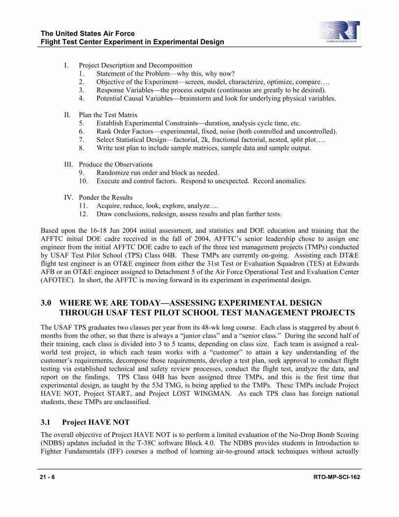
As stated previously, DOE refers to the process of planning the experiment so that appropriate data that can be analyzed by statistical methods will be collected, resulting in valid and objective conclusions. The 53d TMG has “decomposed” this process in what Mr. Greg Hutto describes as “DOE Process Steps—12 Steps – 4 Blocks.” Preliminarily, AFFTC’s senior engineers and initial DOE cadre have embraced these 12 steps in 4 blocks [1, 9]:
The United States Air Force Flight Test Center Experiment in Experimental Design
21 - 6 RTO-MP-SCI-162
I. Project Description and Decomposition 1. Statement of the Problem—why this, why now? 2. Objective of the Experiment—screen, model, characterize, optimize, compare…. 3. Response Variables—the process outputs (continuous are greatly to be desired). 4. Potential Causal Variables—brainstorm and look for underlying physical variables. II. Plan the Test Matrix 5. Establish Experimental Constraints—duration, analysis cycle time, etc. 6. Rank Order Factors—experimental, fixed, noise (both controlled and uncontrolled). 7. Select Statistical Design—factorial, 2k, fractional factorial, nested, split plot…. 8. Write test plan to include sample matrices, sample data and sample output. III. Produce the Observations 9. Randomize run order and block as needed. 10. Execute and control factors. Respond to unexpected. Record anomalies. IV. Ponder the Results 11. Acquire, reduce, look, explore, analyze…. 12. Draw conclusions, redesign, assess results and plan further tests.
Based upon the 16-18 Jun 2004 initial assessment, and statistics and DOE education and training that the AFFTC initial DOE cadre received in the fall of 2004, AFFTC’s senior leadership chose to assign one engineer from the initial AFFTC DOE cadre to each of the three test management projects (TMPs) conducted by USAF Test Pilot School (TPS) Class 04B. These TMPs are currently on-going. Assisting each DT&E flight test engineer is an OT&E engineer from either the 31st Test or Evaluation Squadron (TES) at Edwards AFB or an OT&E engineer assigned to Detachment 5 of the Air Force Operational Test and Evaluation Center (AFOTEC). In short, the AFFTC is moving forward in its experiment in experimental design.
3.0 WHERE WE ARE TODAY—ASSESSING EXPERIMENTAL DESIGN THROUGH USAF TEST PILOT SCHOOL TEST MANAGEMENT PROJECTS
The USAF TPS graduates two classes per year from its 48-wk long course. Each class is staggered by about 6 months from the other, so that there is always a “junior class” and a “senior class.” During the second half of their training, each class is divided into 3 to 5 teams, depending on class size. Each team is assigned a real-world test project, in which each team works with a “customer” to attain a key understanding of the customer’s requirements, decompose those requirements, develop a test plan, seek approval to conduct flight testing via established technical and safety review processes, conduct the flight test, analyze the data, and report on the findings. TPS Class 04B has been assigned three TMPs, and this is the first time that experimental design, as taught by the 53d TMG, is being applied to the TMPs. These TMPs include Project HAVE NOT, Project START, and Project LOST WINGMAN. As each TPS class has foreign national students, these TMPs are unclassified.
3.1 Project HAVE NOT The overall objective of Project HAVE NOT is to perform a limited evaluation of the No-Drop Bomb Scoring (NDBS) updates included in the T-38C software Block 4.0. The NDBS provides students in Introduction to Fighter Fundamentals (IFF) courses a method of learning air-to-ground attack techniques without actually
The United States Air Force Flight Test Center Experiment in Experimental Design
RTO-MP-SCI-162 21 - 7
dropping ordnance. Block 4.0 incorporates a number of fixes to problems with NDBS identified by Air Education and Training Command (AETC) users. Twelve test sorties have been planned for approximately 13.2 flight hours. Testing was requested by the 49th Flying Training Squadron (FTS), Moody AFB, Georgia [10].
Block 4.0 of T-38C software corrects deficiencies noted by instructor pilots during operational use and adds capability of Continuously Computed Release Point (CCRP) deliveries. Testing by the contractor has focused on the new CCRP functionality, with only regression testing performed on the existing Continuously Computed Impact Point (CCIP) deliveries. Project HAVE NOT will perform testing of the CCIP functionality of Block 4.0 [10].
Testing will be performed by utilizing a DOE-based test matrix to determine the effects of various factors on NDBS deliveries. Slant range, airspeed, dive angle, bomb drag (high or low), pipper placement, and terrain variation will be investigated for the accuracy of the deliveries compared to truth ballistics predictions.
The T-38C NDBS provides pilots with air-to-ground symbology emulating either the F-16 or MIL-STD-1787B heads-up-display (HUD). The symbology can be set for CCIP, CCRP (new in Block 4.0), or Manual modes. After the depression of the weapon release button, the NDBS determines the predicted impact point of the bomb and displays the impact point and release conditions to the pilot and instructor pilot on the primary Multi-Function Display (MFD) [10].
Specific areas of interest include the accuracy of simulated bomb drops, correct HUD symbology presentation, and correction of errors induced by attacks performed with varying altitude terrain on approach to targets. Additionally, 49th FTS instructor pilots requested the test team evaluate the AT-38B Combat Weapon Delivery System (CWDS) attack planning system for use by T-38C aircrews [10].
In support of the overall objective, five specific test objectives have been developed:
• Determine the accuracy of NDBS CCIP predictions
• Evaluate HUD symbology
• Compare T-38C delivery parameters to CWDS AT-38B predictions
• Observe the functionality of NDBS over varying terrain approach to targets
• Observe the functionality of NDBS in operationally representative deliveries using CCRP targeting.
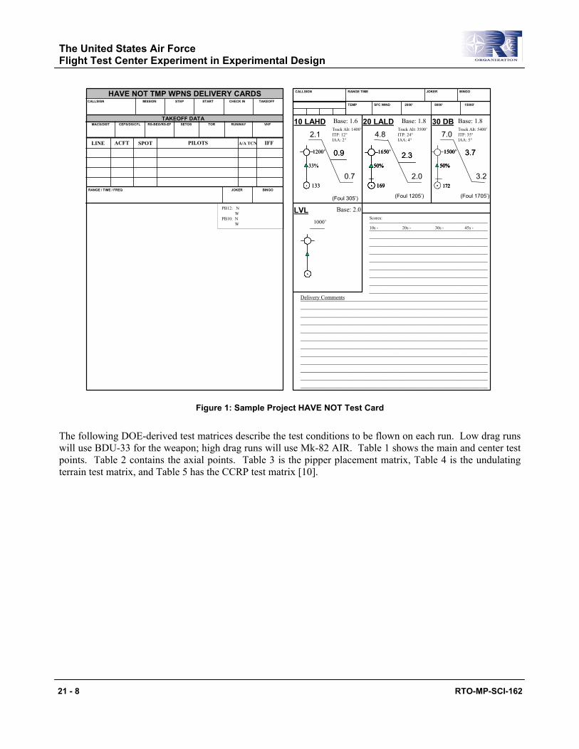
Figure 1 is a sample Project HAVE NOT test card.
The United States Air Force Flight Test Center Experiment in Experimental Design
21 - 8 RTO-MP-SCI-162
JOKER BINGORANGE TIMECALLSIGN
TEMP SFC WIND 2000’ 8000’ 15000’
Delivery Comments
________________________________________________________________________________________________________________________________________________________________________________________________________________________________________________________________________________________________________________________________________________________________________
LVL Base: 2.0
Base: 1.8Track Alt: 3500’ITP: 24°IAA: 4°
20 LALD4.8
2.0
(Foul 1205’)
2.32.31650’
50%
169
1650’
50%
169
1650’
50%
169
50%
169
Base: 1.8
(Foul 1705’)
30 DB7.0
3.2
3.73.7
Track Alt: 5400’ITP: 35°IAA: 5°
1500’
50%
172
1500’
50%
172
1500’
50%
172
50%
172
10 LAHD2.1
0.7
0.90.91200’
33%
133
1200’
33%
133
Track Alt: 1400’ITP: 12°IAA: 2°
Base: 1.6
(Foul 305’)
____________________________________________________________________________________________________________________________________________________________________________________________________________________________________________________________________________________________________________________________________________________________________________________________________________________________________________________________________________________________________________________________________________________________________________________________________________________________________________________________________________________________________________
Scores:
10s - 20s - 30s - 45s -
TAKEOFF DATA
HAVE NOT TMP WPNS DELIVERY CARDS
PB12: N W
PB10: NW
CALLSIGN MISSION START CHECK IN TAKEOFF
TOR RUNWAY VHFCEFS/DS/CFL RS-BEO/RS-EF SETOSMACS/DIST
JOKER BINGO
STEP
SPOTLINE ACFT PILOTS A/A TCN IFF
RANGE / TIME / FREQ
1000’
Figure 1: Sample Project HAVE NOT Test Card
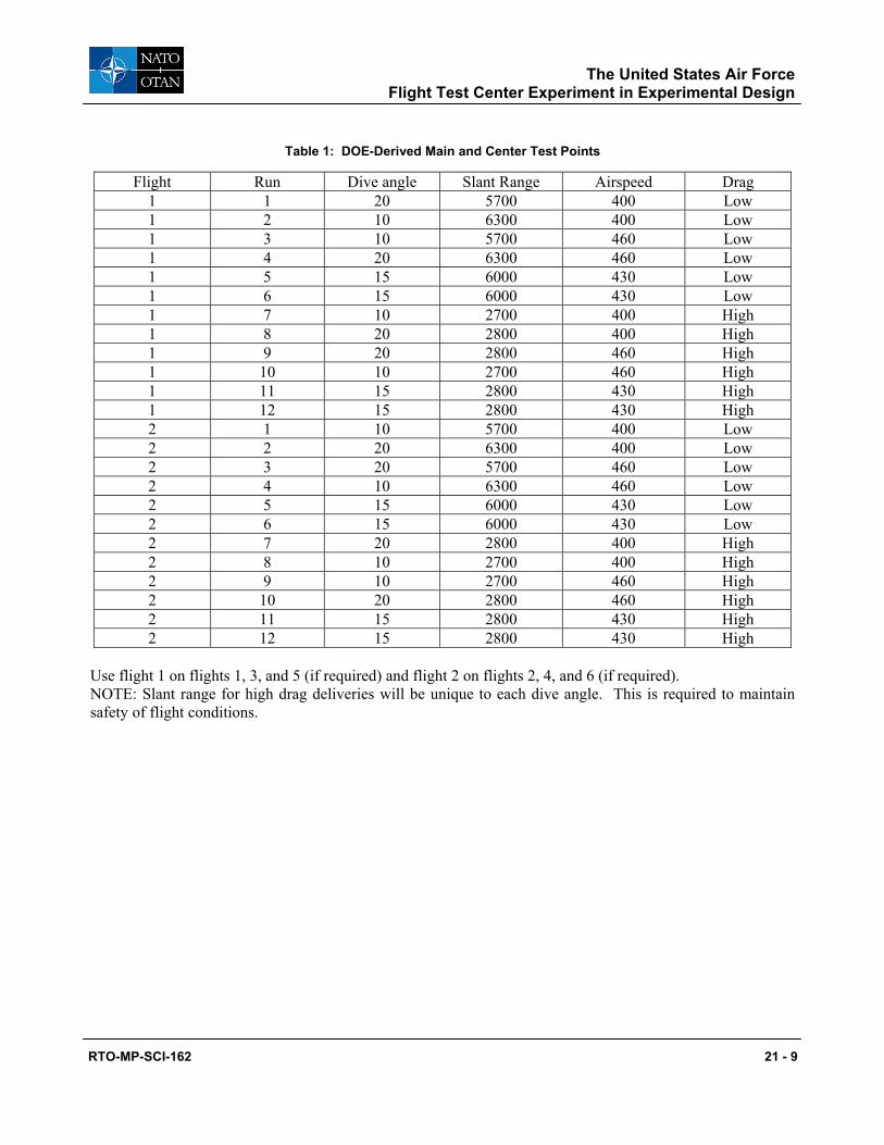
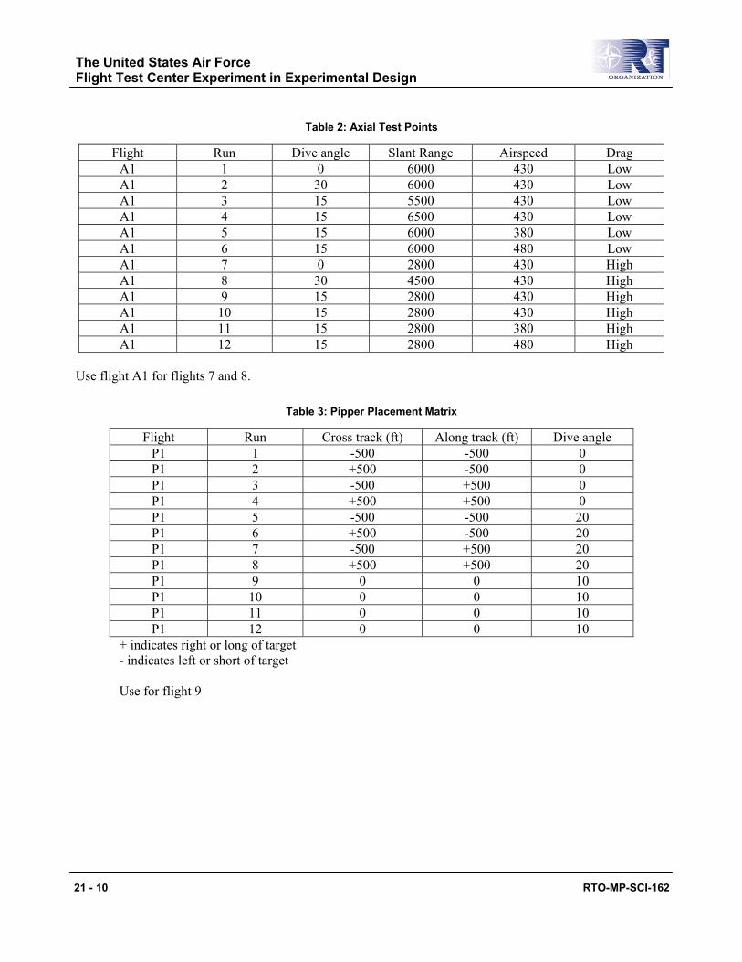
The following DOE-derived test matrices describe the test conditions to be flown on each run. Low drag runs will use BDU-33 for the weapon; high drag runs will use Mk-82 AIR. Table 1 shows the main and center test points. Table 2 contains the axial points. Table 3 is the pipper placement matrix, Table 4 is the undulating terrain test matrix, and Table 5 has the CCRP test matrix [10].
The United States Air Force Flight Test Center Experiment in Experimental Design
RTO-MP-SCI-162 21 - 9
Table 1: DOE-Derived Main and Center Test Points
Flight Run Dive angle Slant Range Airspeed Drag 1 1 20 5700 400 Low 1 2 10 6300 400 Low 1 3 10 5700 460 Low 1 4 20 6300 460 Low 1 5 15 6000 430 Low 1 6 15 6000 430 Low 1 7 10 2700 400 High 1 8 20 2800 400 High 1 9 20 2800 460 High 1 10 10 2700 460 High 1 11 15 2800 430 High 1 12 15 2800 430 High 2 1 10 5700 400 Low 2 2 20 6300 400 Low 2 3 20 5700 460 Low 2 4 10 6300 460 Low 2 5 15 6000 430 Low 2 6 15 6000 430 Low 2 7 20 2800 400 High 2 8 10 2700 400 High 2 9 10 2700 460 High 2 10 20 2800 460 High 2 11 15 2800 430 High 2 12 15 2800 430 High
Use flight 1 on flights 1, 3, and 5 (if required) and flight 2 on flights 2, 4, and 6 (if required). NOTE: Slant range for high drag deliveries will be unique to each dive angle. This is required to maintain safety of flight conditions.
The United States Air Force Flight Test Center Experiment in Experimental Design
21 - 10 RTO-MP-SCI-162
Table 2: Axial Test Points
Flight Run Dive angle Slant Range Airspeed Drag A1 1 0 6000 430 Low A1 2 30 6000 430 Low A1 3 15 5500 430 Low A1 4 15 6500 430 Low A1 5 15 6000 380 Low A1 6 15 6000 480 Low A1 7 0 2800 430 High A1 8 30 4500 430 High A1 9 15 2800 430 High A1 10 15 2800 430 High A1 11 15 2800 380 High A1 12 15 2800 480 High
Use flight A1 for flights 7 and 8.
Table 3: Pipper Placement Matrix
Flight Run Cross track (ft) Along track (ft) Dive angle P1 1 -500 -500 0 P1 2 +500 -500 0 P1 3 -500 +500 0 P1 4 +500 +500 0 P1 5 -500 -500 20 P1 6 +500 -500 20 P1 7 -500 +500 20 P1 8 +500 +500 20 P1 9 0 0 10 P1 10 0 0 10 P1 11 0 0 10 P1 12 0 0 10
+ indicates right or long of target - indicates left or short of target Use for flight 9
The United States Air Force Flight Test Center Experiment in Experimental Design
RTO-MP-SCI-162 21 - 11
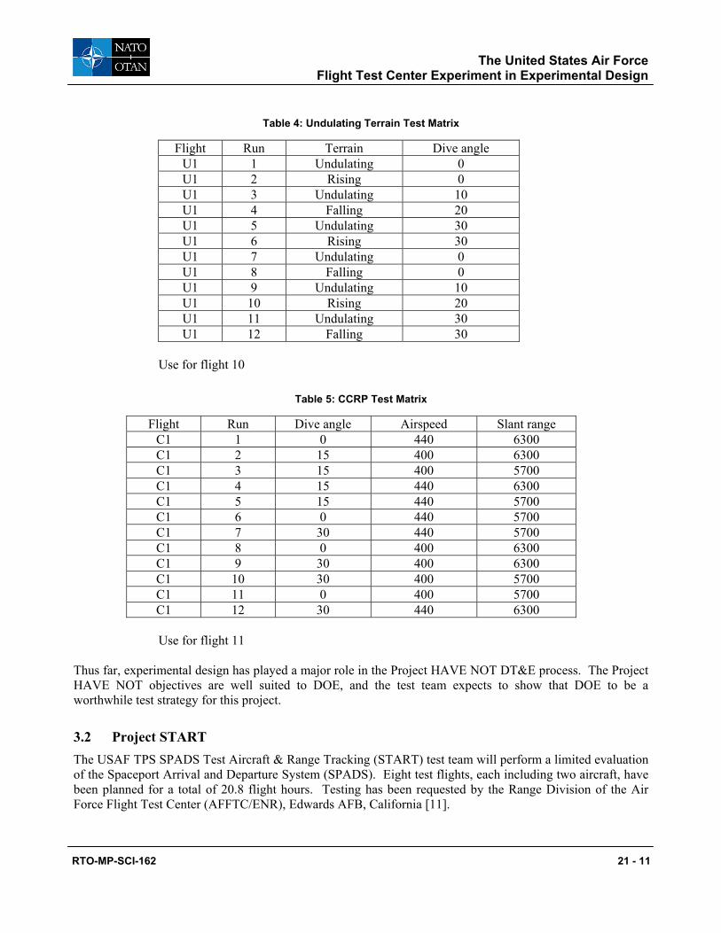
Table 4: Undulating Terrain Test Matrix
Flight Run Terrain Dive angle U1 1 Undulating 0 U1 2 Rising 0 U1 3 Undulating 10 U1 4 Falling 20 U1 5 Undulating 30 U1 6 Rising 30 U1 7 Undulating 0 U1 8 Falling 0 U1 9 Undulating 10 U1 10 Rising 20 U1 11 Undulating 30 U1 12 Falling 30
Use for flight 10
Table 5: CCRP Test Matrix
Flight Run Dive angle Airspeed Slant range C1 1 0 440 6300 C1 2 15 400 6300 C1 3 15 400 5700 C1 4 15 440 6300 C1 5 15 440 5700 C1 6 0 440 5700 C1 7 30 440 5700 C1 8 0 400 6300 C1 9 30 400 6300 C1 10 30 400 5700 C1 11 0 400 5700 C1 12 30 440 6300 Use for flight 11
Thus far, experimental design has played a major role in the Project HAVE NOT DT&E process. The Project HAVE NOT objectives are well suited to DOE, and the test team expects to show that DOE to be a worthwhile test strategy for this project.
3.2 Project START The USAF TPS SPADS Test Aircraft & Range Tracking (START) test team will perform a limited evaluation of the Spaceport Arrival and Departure System (SPADS). Eight test flights, each including two aircraft, have been planned for a total of 20.8 flight hours. Testing has been requested by the Range Division of the Air Force Flight Test Center (AFFTC/ENR), Edwards AFB, California [11].
The United States Air Force Flight Test Center Experiment in Experimental Design
21 - 12 RTO-MP-SCI-162
The overall test objective is to characterize the SPADS radar system for use as a single-station time space positioning information (TSPI) source. The tests will include aircraft tracking as compared to Advanced Range Data System (ARDS) pod data, munitions trajectory tracking as compared to cinetheodolite data and bomb scoring capability compared to site survey data. Multi-object tracking capability will also be demonstrated [11].
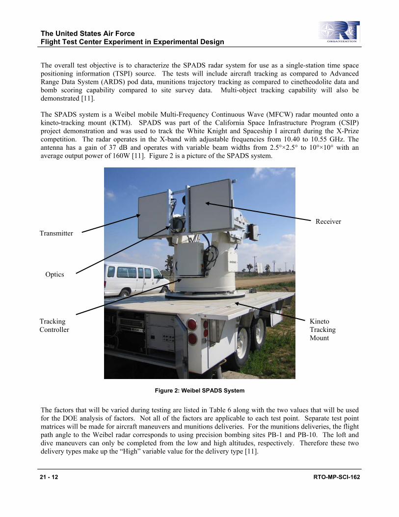
The SPADS system is a Weibel mobile Multi-Frequency Continuous Wave (MFCW) radar mounted onto a kineto-tracking mount (KTM). SPADS was part of the California Space Infrastructure Program (CSIP) project demonstration and was used to track the White Knight and Spaceship I aircraft during the X-Prize competition. The radar operates in the X-band with adjustable frequencies from 10.40 to 10.55 GHz. The antenna has a gain of 37 dB and operates with variable beam widths from 2.5°×2.5° to 10°×10° with an average output power of 160W [11]. Figure 2 is a picture of the SPADS system.
Figure 2: Weibel SPADS System
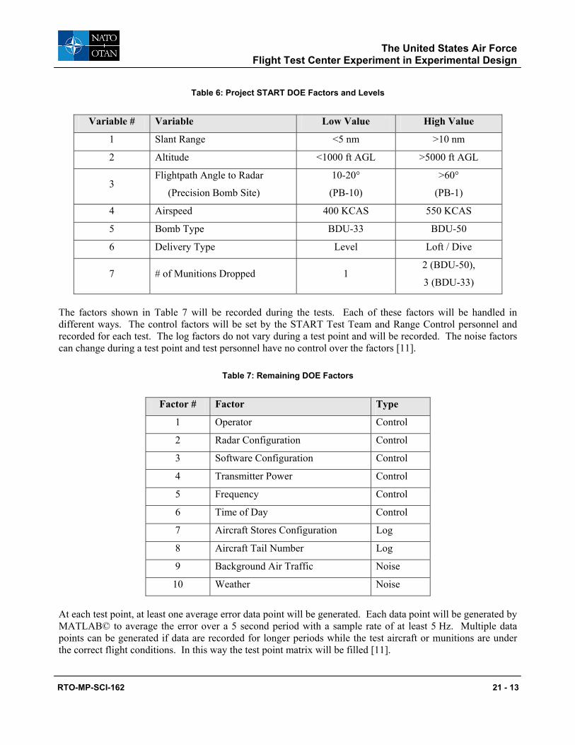
The factors that will be varied during testing are listed in Table 6 along with the two values that will be used for the DOE analysis of factors. Not all of the factors are applicable to each test point. Separate test point matrices will be made for aircraft maneuvers and munitions deliveries. For the munitions deliveries, the flight path angle to the Weibel radar corresponds to using precision bombing sites PB-1 and PB-10. The loft and dive maneuvers can only be completed from the low and high altitudes, respectively. Therefore these two delivery types make up the “High” variable value for the delivery type [11].
Transmitter Receiver
Kineto Tracking Mount
Tracking Controller
Optics
The United States Air Force Flight Test Center Experiment in Experimental Design
RTO-MP-SCI-162 21 - 13
Table 6: Project START DOE Factors and Levels
Variable # Variable Low Value High Value
1 Slant Range <5 nm >10 nm
2 Altitude <1000 ft AGL >5000 ft AGL
3 Flightpath Angle to Radar
(Precision Bomb Site)
10-20°
(PB-10)
>60°
(PB-1)
4 Airspeed 400 KCAS 550 KCAS
5 Bomb Type BDU-33 BDU-50
6 Delivery Type Level Loft / Dive
7 # of Munitions Dropped 1 2 (BDU-50),
3 (BDU-33)
The factors shown in Table 7 will be recorded during the tests. Each of these factors will be handled in different ways. The control factors will be set by the START Test Team and Range Control personnel and recorded for each test. The log factors do not vary during a test point and will be recorded. The noise factors can change during a test point and test personnel have no control over the factors [11].
Table 7: Remaining DOE Factors
Factor # Factor Type
1 Operator Control
2 Radar Configuration Control
3 Software Configuration Control
4 Transmitter Power Control
5 Frequency Control
6 Time of Day Control
7 Aircraft Stores Configuration Log
8 Aircraft Tail Number Log
9 Background Air Traffic Noise
10 Weather Noise
At each test point, at least one average error data point will be generated. Each data point will be generated by MATLAB© to average the error over a 5 second period with a sample rate of at least 5 Hz. Multiple data points can be generated if data are recorded for longer periods while the test aircraft or munitions are under the correct flight conditions. In this way the test point matrix will be filled [11].
The United States Air Force Flight Test Center Experiment in Experimental Design
21 - 14 RTO-MP-SCI-162
Once the data points are complete, the Statistica© program will be used to complete the analyses of variance for each of the DOE factors. In this way, it can be determined which of the factors have the greatest influence on the error and the confidence intervals associated with each active factor.
Similar to Project HAVE NOT, Project START test team members predict that DOE will be assessed in the end to be a worthwhile test strategy for use in this DT&E flight test program.
3.3 Project LOST WINGMAN The purpose of Project LOST WINGMAN is to evaluate the accuracy of a real-time relative position solution using a datalink of global positioning system (GPS) and inertial measurement unit (IMU) information between two C-12Cs. The overall test objective is to perform a limited evaluation of the relative GPS datalink system between two C-12 aircraft. This evaluation will be broken into three objectives:
• Objective 1—Demonstrate the accuracy of the relative position solution
• Objective 2—Observe the accuracy of the Micro-Electro-Mechanical System Inertial Measurement Unit (MEMS IMU), and
• Objective 3—Observe the datalink functionality [12].
Project LOST WINGMAN is a risk-reduction program for follow-on testing using the datalink as a control input for a Learjet flying in formation behind a C-12C. Thus, the GPS and attitude information from the lead aircraft will be transmitted over the datalink to determine the position where the autonomous vehicle must fly. Project LOST WINGMAN will be conducted at the request of the Air Force Institute of Technology (AFIT), Department of Electrical and Computer Engineering (AFIT/ENG) [12].
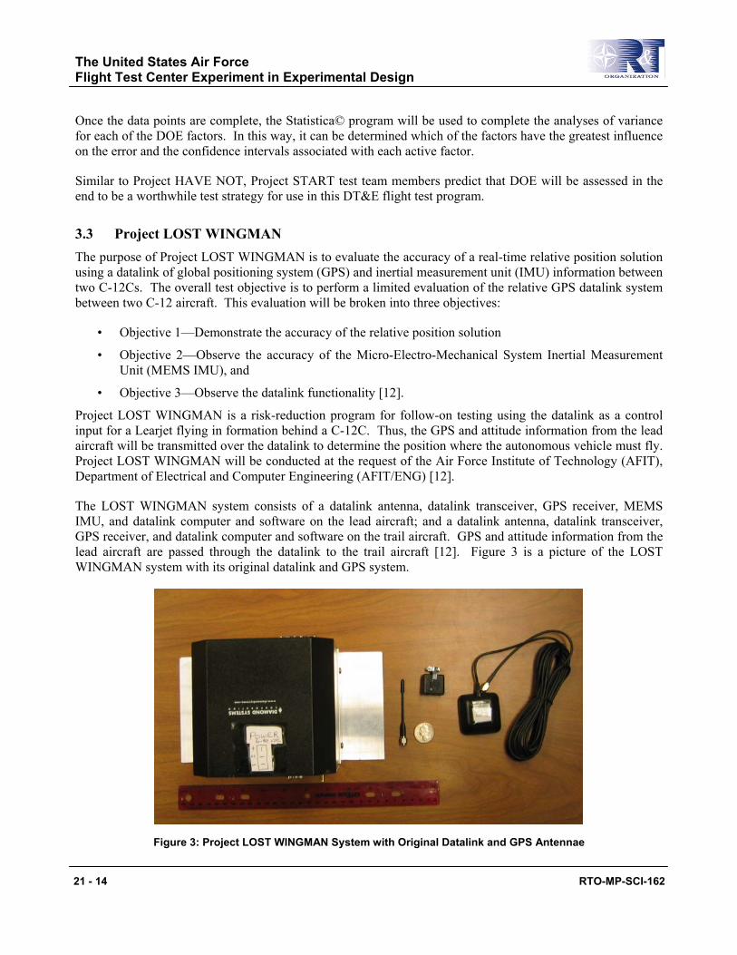
The LOST WINGMAN system consists of a datalink antenna, datalink transceiver, GPS receiver, MEMS IMU, and datalink computer and software on the lead aircraft; and a datalink antenna, datalink transceiver, GPS receiver, and datalink computer and software on the trail aircraft. GPS and attitude information from the lead aircraft are passed through the datalink to the trail aircraft [12]. Figure 3 is a picture of the LOST WINGMAN system with its original datalink and GPS system.
Figure 3: Project LOST WINGMAN System with Original Datalink and GPS Antennae
The United States Air Force Flight Test Center Experiment in Experimental Design
RTO-MP-SCI-162 21 - 15
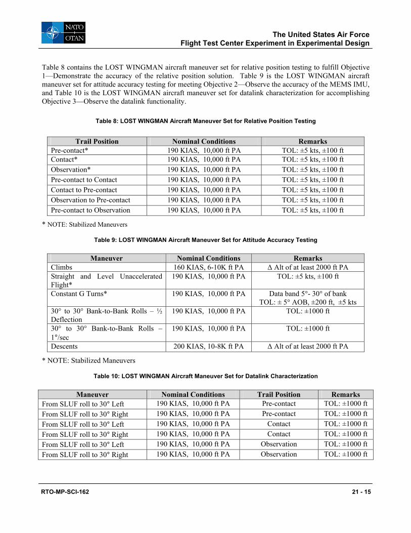
Table 8 contains the LOST WINGMAN aircraft maneuver set for relative position testing to fulfill Objective 1—Demonstrate the accuracy of the relative position solution. Table 9 is the LOST WINGMAN aircraft maneuver set for attitude accuracy testing for meeting Objective 2—Observe the accuracy of the MEMS IMU, and Table 10 is the LOST WINGMAN aircraft maneuver set for datalink characterization for accomplishing Objective 3—Observe the datalink functionality.
Table 8: LOST WINGMAN Aircraft Maneuver Set for Relative Position Testing
Trail Position Nominal Conditions Remarks Pre-contact* 190 KIAS, 10,000 ft PA TOL: ±5 kts, ±100 ft Contact* 190 KIAS, 10,000 ft PA TOL: ±5 kts, ±100 ft Observation* 190 KIAS, 10,000 ft PA TOL: ±5 kts, ±100 ft Pre-contact to Contact 190 KIAS, 10,000 ft PA TOL: ±5 kts, ±100 ft Contact to Pre-contact 190 KIAS, 10,000 ft PA TOL: ±5 kts, ±100 ft Observation to Pre-contact 190 KIAS, 10,000 ft PA TOL: ±5 kts, ±100 ft Pre-contact to Observation 190 KIAS, 10,000 ft PA TOL: ±5 kts, ±100 ft
* NOTE: Stabilized Maneuvers
Table 9: LOST WINGMAN Aircraft Maneuver Set for Attitude Accuracy Testing
Maneuver Nominal Conditions Remarks Climbs 160 KIAS, 6-10K ft PA ∆ Alt of at least 2000 ft PA Straight and Level Unaccelerated Flight*
190 KIAS, 10,000 ft PA TOL: ±5 kts, ±100 ft
Constant G Turns* 190 KIAS, 10,000 ft PA Data band 5°- 30° of bank TOL: ± 5° AOB, ±200 ft, ±5 kts
30° to 30° Bank-to-Bank Rolls – ½ Deflection
190 KIAS, 10,000 ft PA TOL: ±1000 ft
30° to 30° Bank-to-Bank Rolls – 1°/sec
190 KIAS, 10,000 ft PA TOL: ±1000 ft
Descents 200 KIAS, 10-8K ft PA ∆ Alt of at least 2000 ft PA
* NOTE: Stabilized Maneuvers
Table 10: LOST WINGMAN Aircraft Maneuver Set for Datalink Characterization
Maneuver Nominal Conditions Trail Position Remarks From SLUF roll to 30° Left 190 KIAS, 10,000 ft PA Pre-contact TOL: ±1000 ft From SLUF roll to 30° Right 190 KIAS, 10,000 ft PA Pre-contact TOL: ±1000 ft From SLUF roll to 30° Left 190 KIAS, 10,000 ft PA Contact TOL: ±1000 ft From SLUF roll to 30° Right 190 KIAS, 10,000 ft PA Contact TOL: ±1000 ft From SLUF roll to 30° Left 190 KIAS, 10,000 ft PA Observation TOL: ±1000 ft From SLUF roll to 30° Right 190 KIAS, 10,000 ft PA Observation TOL: ±1000 ft
The United States Air Force Flight Test Center Experiment in Experimental Design
21 - 16 RTO-MP-SCI-162
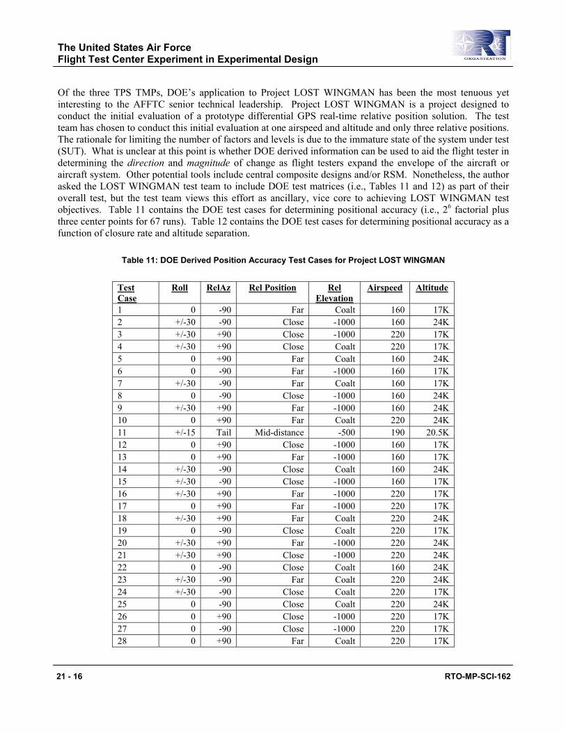
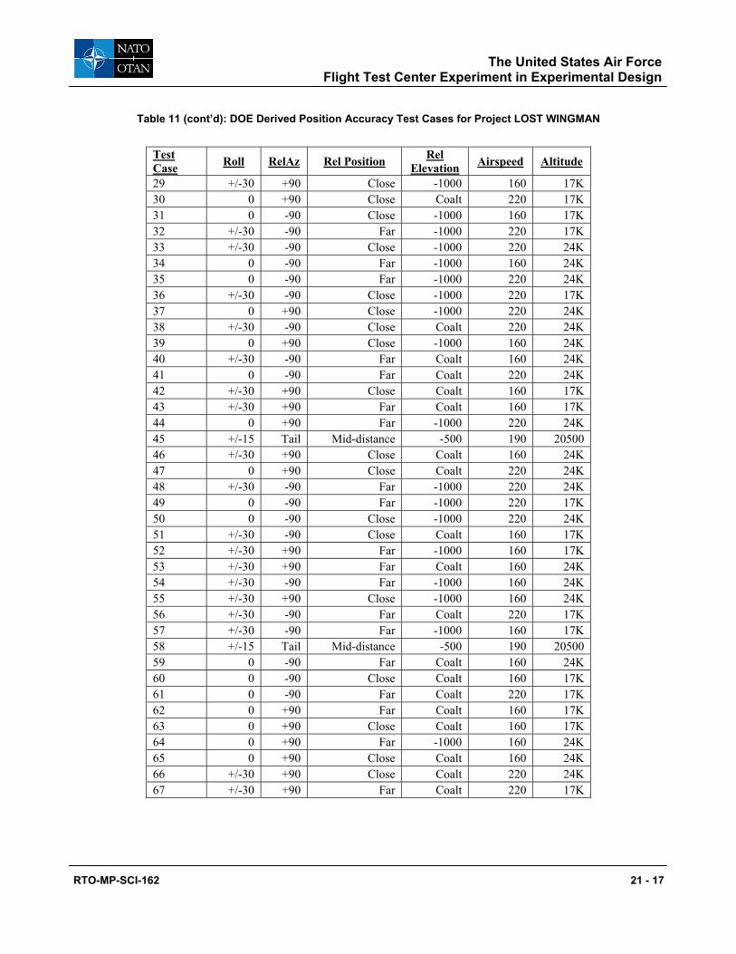
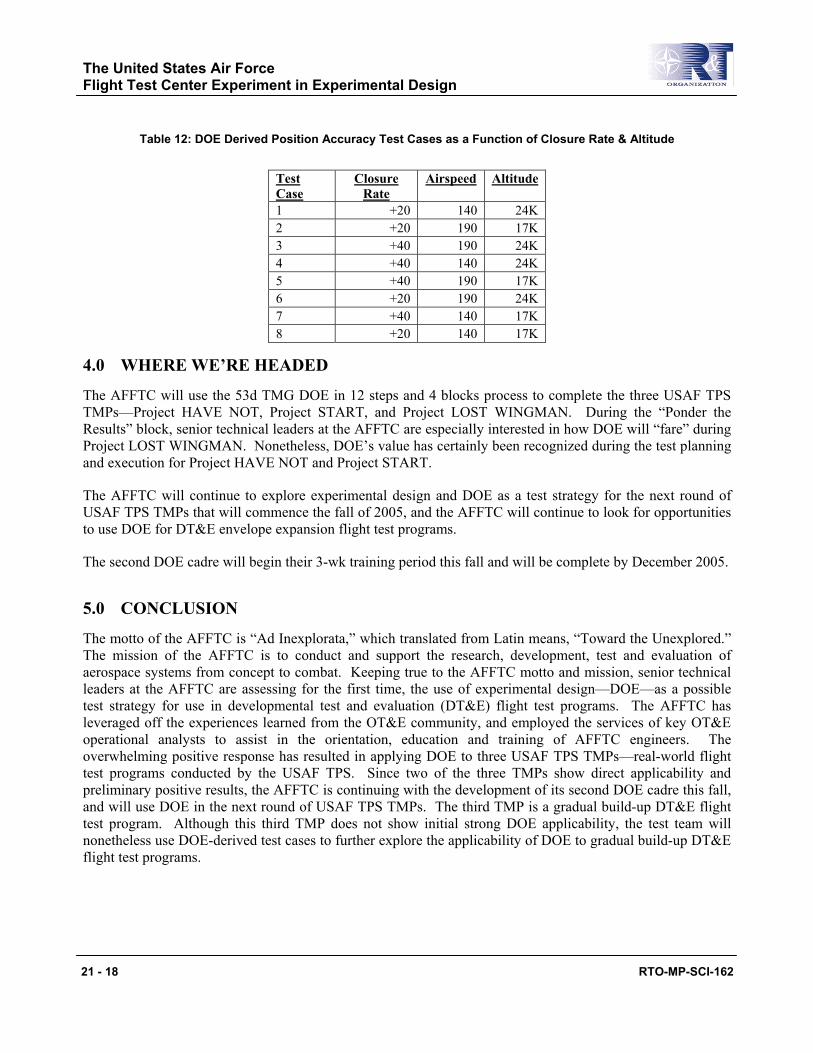
Of the three TPS TMPs, DOE’s application to Project LOST WINGMAN has been the most tenuous yet interesting to the AFFTC senior technical leadership. Project LOST WINGMAN is a project designed to conduct the initial evaluation of a prototype differential GPS real-time relative position solution. The test team has chosen to conduct this initial evaluation at one airspeed and altitude and only three relative positions. The rationale for limiting the number of factors and levels is due to the immature state of the system under test (SUT). What is unclear at this point is whether DOE derived information can be used to aid the flight tester in determining the direction and magnitude of change as flight testers expand the envelope of the aircraft or aircraft system. Other potential tools include central composite designs and/or RSM. Nonetheless, the author asked the LOST WINGMAN test team to include DOE test matrices (i.e., Tables 11 and 12) as part of their overall test, but the test team views this effort as ancillary, vice core to achieving LOST WINGMAN test objectives. Table 11 contains the DOE test cases for determining positional accuracy (i.e., 26 factorial plus three center points for 67 runs). Table 12 contains the DOE test cases for determining positional accuracy as a function of closure rate and altitude separation.
Table 11: DOE Derived Position Accuracy Test Cases for Project LOST WINGMAN
Test Case
Roll RelAz Rel Position Rel Elevation
Airspeed Altitude
1 0 -90 Far Coalt 160 17K 2 +/-30 -90 Close -1000 160 24K 3 +/-30 +90 Close -1000 220 17K 4 +/-30 +90 Close Coalt 220 17K 5 0 +90 Far Coalt 160 24K 6 0 -90 Far -1000 160 17K 7 +/-30 -90 Far Coalt 160 17K 8 0 -90 Close -1000 160 24K 9 +/-30 +90 Far -1000 160 24K 10 0 +90 Far Coalt 220 24K 11 +/-15 Tail Mid-distance -500 190 20.5K 12 0 +90 Close -1000 160 17K 13 0 +90 Far -1000 160 17K 14 +/-30 -90 Close Coalt 160 24K 15 +/-30 -90 Close -1000 160 17K 16 +/-30 +90 Far -1000 220 17K 17 0 +90 Far -1000 220 17K 18 +/-30 +90 Far Coalt 220 24K 19 0 -90 Close Coalt 220 17K 20 +/-30 +90 Far -1000 220 24K 21 +/-30 +90 Close -1000 220 24K 22 0 -90 Close Coalt 160 24K 23 +/-30 -90 Far Coalt 220 24K 24 +/-30 -90 Close Coalt 220 17K 25 0 -90 Close Coalt 220 24K 26 0 +90 Close -1000 220 17K 27 0 -90 Close -1000 220 17K 28 0 +90 Far Coalt 220 17K
The United States Air Force Flight Test Center Experiment in Experimental Design
RTO-MP-SCI-162 21 - 17
Table 11 (cont’d): DOE Derived Position Accuracy Test Cases for Project LOST WINGMAN
Test Case Roll RelAz Rel Position Rel
Elevation Airspeed Altitude
29 +/-30 +90 Close -1000 160 17K 30 0 +90 Close Coalt 220 17K 31 0 -90 Close -1000 160 17K 32 +/-30 -90 Far -1000 220 17K 33 +/-30 -90 Close -1000 220 24K 34 0 -90 Far -1000 160 24K 35 0 -90 Far -1000 220 24K 36 +/-30 -90 Close -1000 220 17K 37 0 +90 Close -1000 220 24K 38 +/-30 -90 Close Coalt 220 24K 39 0 +90 Close -1000 160 24K 40 +/-30 -90 Far Coalt 160 24K 41 0 -90 Far Coalt 220 24K 42 +/-30 +90 Close Coalt 160 17K 43 +/-30 +90 Far Coalt 160 17K 44 0 +90 Far -1000 220 24K 45 +/-15 Tail Mid-distance -500 190 20500 46 +/-30 +90 Close Coalt 160 24K 47 0 +90 Close Coalt 220 24K 48 +/-30 -90 Far -1000 220 24K 49 0 -90 Far -1000 220 17K 50 0 -90 Close -1000 220 24K 51 +/-30 -90 Close Coalt 160 17K 52 +/-30 +90 Far -1000 160 17K 53 +/-30 +90 Far Coalt 160 24K 54 +/-30 -90 Far -1000 160 24K 55 +/-30 +90 Close -1000 160 24K 56 +/-30 -90 Far Coalt 220 17K 57 +/-30 -90 Far -1000 160 17K 58 +/-15 Tail Mid-distance -500 190 20500 59 0 -90 Far Coalt 160 24K 60 0 -90 Close Coalt 160 17K 61 0 -90 Far Coalt 220 17K 62 0 +90 Far Coalt 160 17K 63 0 +90 Close Coalt 160 17K 64 0 +90 Far -1000 160 24K 65 0 +90 Close Coalt 160 24K 66 +/-30 +90 Close Coalt 220 24K 67 +/-30 +90 Far Coalt 220 17K
The United States Air Force Flight Test Center Experiment in Experimental Design
21 - 18 RTO-MP-SCI-162
Table 12: DOE Derived Position Accuracy Test Cases as a Function of Closure Rate & Altitude
Test Case
Closure Rate
Airspeed Altitude
1 +20 140 24K 2 +20 190 17K 3 +40 190 24K 4 +40 140 24K 5 +40 190 17K 6 +20 190 24K 7 +40 140 17K 8 +20 140 17K
4.0 WHERE WE’RE HEADED
The AFFTC will use the 53d TMG DOE in 12 steps and 4 blocks process to complete the three USAF TPS TMPs—Project HAVE NOT, Project START, and Project LOST WINGMAN. During the “Ponder the Results” block, senior technical leaders at the AFFTC are especially interested in how DOE will “fare” during Project LOST WINGMAN. Nonetheless, DOE’s value has certainly been recognized during the test planning and execution for Project HAVE NOT and Project START.
The AFFTC will continue to explore experimental design and DOE as a test strategy for the next round of USAF TPS TMPs that will commence the fall of 2005, and the AFFTC will continue to look for opportunities to use DOE for DT&E envelope expansion flight test programs.
The second DOE cadre will begin their 3-wk training period this fall and will be complete by December 2005.
5.0 CONCLUSION
The motto of the AFFTC is “Ad Inexplorata,” which translated from Latin means, “Toward the Unexplored.” The mission of the AFFTC is to conduct and support the research, development, test and evaluation of aerospace systems from concept to combat. Keeping true to the AFFTC motto and mission, senior technical leaders at the AFFTC are assessing for the first time, the use of experimental design—DOE—as a possible test strategy for use in developmental test and evaluation (DT&E) flight test programs. The AFFTC has leveraged off the experiences learned from the OT&E community, and employed the services of key OT&E operational analysts to assist in the orientation, education and training of AFFTC engineers. The overwhelming positive response has resulted in applying DOE to three USAF TPS TMPs—real-world flight test programs conducted by the USAF TPS. Since two of the three TMPs show direct applicability and preliminary positive results, the AFFTC is continuing with the development of its second DOE cadre this fall, and will use DOE in the next round of USAF TPS TMPs. The third TMP is a gradual build-up DT&E flight test program. Although this third TMP does not show initial strong DOE applicability, the test team will nonetheless use DOE-derived test cases to further explore the applicability of DOE to gradual build-up DT&E flight test programs.
The United States Air Force Flight Test Center Experiment in Experimental Design
RTO-MP-SCI-162 21 - 19
6.0 REFERENCES
[1] Hutto, G. (2004). Test For Leaders—What You Should Know. 53d Test Management Group, 53d Wing, Air Combat Command.
[2] Hutto, G. & Akerson, J. (2004). Raising the Bar: Equipping 53d Wing Test Teams to Excel with DOE. 53d Test Management Group, 53d Wing, Air Combat Command.
[3] Defense Systems Management College Press (1998). Glossary of Defense Acquisition Acronyms and Terms. Ninth Edition. Fort Belvoir, Virginia.
[4] Montgomery, D. (2001). Design and Analysis of Experiments. Fifth Edition. John, Wiley & Sons, Inc.
[5] Survey results (2004). Should the AFFTC consider using DOE?” DOE Orientation Course. AFFTC.
[6] Survey results (2004). Should the AFFTC implement DOE? DOE for Leaders Course. AFFTC.
[7] Hutto, G. (2004). Basic Statistics Review: Foundations for Designed Experiments. 53d Test Management Group, 53d Wing, Air Combat Command.
[8] Triola, M. (2005). Elementary Statistics. Ninth Edition. Pearson, Addison Wesley.
[9] Hutto, G. (2004). Applied DOE I & II: ANOVA and Factorial Experiments. 53d Test Management Group, 53d Wing, Air Combat Command.
[10] Coil, J., et al. (2005). Limited Evaluation of the T-38C Block 4.0 No-Drop Bomb Scoring (PROJECT “HAVE NOT”) [DRAFT]. USAF Test Pilot School, Air Force Flight Test Center.
[11] Roessig, K., et al. (2005). SPADS Test Aircraft & Range Tracking Project “START” Limited Evaluation of the SPADS Radar System [DRAFT]. USAF Test Pilot School, Air Force Flight Test Center.
[12] George, B., et al. (2005). Limited Evaluation of a Relative GPS Datalink Between Two C-12s [DRAFT]. USAF Test Pilot School, Air Force Flight Test Center.
7.0 ACRONYM LIST
53 WG—53d Wing ACC—Air Combat Command AETC—Air Education Training Center AFB—Air Force Base AFFTC—Air Force Flight Test Center AFIT—Air Force Institute of Technology AFOTEC—Air Force Operational Test and Evaluation Center AMRAAM—Advanced Medium Range Air-to-Air Missile ARDS—Advance Range Data System CCIP—Continuously Computed Impact Point CCRP—Continuously Computed Release Point CSIP—California Space Infrastructure Program
The United States Air Force Flight Test Center Experiment in Experimental Design
21 - 20 RTO-MP-SCI-162
CWDS—Combat Display Weapon System DOE—Design of Experiments DOF—Degree of Freedom DT&E—Developmental Test and Evaluation ECM—Electronic Countermeasures FTE—Flight Test Engineer FTS—Flying Training Squadron GPS—Global Positioning System HWIL—Hardware in the Loop IFF—Introduction to Fighter Fundamentals IMU—Inertial Measurement Unit JDAM—Joint Direct Attack Munitions MEMS IMU—Micro-Electro-Mechanical System Inertial Measurement Unit MFCW—Multi-Frequency Continuous Wave MFD—Multi-Function Display NDBS—No-Drop Bomb Scoring OFAT—One Factor At a Time OFP—Operational Flight Program RSM—Response Surface Methodology SoS—System of Systems SPADS—Spaceport Arrival and Departure System SPO—System Program Office START—SPADS Test Aircraft and Range Tracking SUT—System Under Test T&E—Test and Evaluation TES—Test and Evaluation Squadron TMG—Test Management Group TMP—Test Management Project TPS—Test Pilot School TSPI—Time Space Positioning Information TSPR—Total System Performance Responsibility USAF—United States Air Force