The Tire as an Intelligent Sensor
15
IEEE TRANSACTIONS ON COMPUTER-AIDED DESIGN OF INTEGRATED CIRCUITS AND SYSTEMS, VOL. 28, NO. 7, JULY 2009 941 The Tire as an Intelligent Sensor Sinem Coleri Ergen, Member, IEEE, Alberto Sangiovanni-Vincentelli, Fellow, IEEE, Xuening Sun, Member, IEEE, Riccardo Tebano, Sayf Alalusi, Giorgio Audisio, and Marco Sabatini Abstract—Active safety systems are based upon the accurate and fast estimation of the value of important dynamical variables such as forces, load transfer, actual tire–road friction (kinetic friction) μ k , and maximum tire–road friction available (potential friction) μ p . Measuring these parameters directly from tires offers the potential for improving significantly the performance of active safety systems. We present a distributed architecture for a data- acquisition system that is based on a number of complex intelligent sensors inside the tire that form a wireless sensor network with coordination nodes placed on the body of the car. The design of this system has been extremely challenging due to the very limited available energy combined with strict application requirements for data rate, delay, size, weight, and reliability in a highly dy- namical environment. Moreover, it required expertise in multiple engineering disciplines, including control-system design, signal processing, integrated-circuit design, communications, real-time software design, antenna design, energy scavenging, and system assembly. Index Terms—Automotive safety, energy efficiency, energy scav- enging, heterogeneous systems, intelligent systems, platform-based design, tires, ultrawideband, wireless sensors. I. I NTRODUCTION T HE ELECTRONICS industry ecosystem is undergoing a radical change driven by an emerging three-layered architecture characterized by the following features: 1) computing and communication infrastructure that will offer increasingly faster data transfer and manipulation via powerful data centers, compute farms, and wired interconnection; 2) access devices such as PDAs, cell phones, and laptops that allow leveraging of the immense capabilities of the infrastructure for users, which can be humans or any of the intelligent physical systems as follows; 3) a swarm of sensors, actuators, and local computing ca- pabilities immersed in all kinds of physical systems that offer a wide variety of personal or broad-use services, Manuscript received July 14, 2008; revised November 13, 2008. Current version published June 17, 2009. This work was supported in part by the Gigascale System Research Center, by the MICRO program of the State of California, and by the Artist Design Network of Excellence. This paper was recommended by Associate Editor M. Di Natale. S. C. Ergen is with the Pirelli/Telecom Italia, Wireless Sensor Networks Berkeley Laboratory, Berkeley, CA 94704 USA. A. Sangiovanni-Vincentelli and X. Sun are with the Department of Elec- trical Engineering and Computer Science, University of California, Berkeley, Berkeley, CA 94720-1500 USA (e-mail: [email protected]). R. Tebano, G. Audisio, and M. Sabatini are with Pirelli Tyres S.p.A., 20126 Milano, Italy (e-mail: [email protected]). S. Alalusi was with the Pirelli/Telecom Italia, Wireless Sensor Networks Berkeley Laboratory, Berkeley, CA 94704 USA. He is now with TransRobotics, San Francisco Bay Area, Hayward, CA 94545 USA. Color versions of one or more of the figures in this paper are available online at http://ieeexplore.ieee.org. Digital Object Identifier 10.1109/TCAD.2009.2022879 Fig. 1. 360 ◦ integrated safety. e.g., a mechanical system such as an automobile, a train, or a plane; an electrical system such as an electrical motor or generator; a chemical system such as a distillation plant; health-care equipment such as a pacemaker; a distributed environment monitoring and control system or a security system for access control to protected areas. In particular, this evolution will have a dramatic effect on automobiles, particularly when considering safety. Road-traffic injuries still represent about 25% of worldwide injury-related deaths (the leading cause) with an estimated 1.2 million deaths (2004) each year [9]. Passive safety devices, such as crumple zones, seat belts, and airbags, work passively to prevent injuries and are standards today. Obviously, these devices, albeit effec- tive, are nowhere near to preventing accidents. Active safety is the frontier for original equipment manufacturers and suppliers to eliminate deadly accidents. Active safety systems use infor- mation about the external environment of a vehicle to change its behavior in precrash time period or during the crash event, with the ultimate goal of avoiding a crash altogether. The zero- accident car includes both autonomous systems, such as radar- based crash-avoidance systems, and cooperative systems that rely on vehicle-to-vehicle and vehicle-to-infrastructure (and vice versa) communication. Eventually, we believe autonomous driving will be possible based on wireless and wired networks of powerful sensors (see Fig. 1, courtesy of General Motors) and complex control algorithms implemented on a distributed computing platform. In fact, research efforts into autonomous accident-free vehicles began in the 1980s with the EUREKA Prometheus project [7]. Early work on active safety systems were primarily focused on improving the longitudinal motion dynamics, particularly on more effective antilock braking systems and traction-control (TC) systems. TC systems prevent the wheel from slipping while improving vehicle stability and control by maximizing the tractive and lateral forces between the vehicle’s tire and 0278-0070/$25.00 © 2009 IEEE Authorized licensed use limited to: Univ of Calif Berkeley. Downloaded on July 20, 2009 at 17:59 from IEEE Xplore. Restrictions apply.
Transcript of The Tire as an Intelligent Sensor

IEEE TRANSACTIONS ON COMPUTER-AIDED DESIGN OF INTEGRATED CIRCUITS AND SYSTEMS, VOL. 28, NO. 7, JULY 2009 941
The Tire as an Intelligent SensorSinem Coleri Ergen, Member, IEEE, Alberto Sangiovanni-Vincentelli, Fellow, IEEE, Xuening Sun, Member, IEEE,
Riccardo Tebano, Sayf Alalusi, Giorgio Audisio, and Marco Sabatini
Abstract—Active safety systems are based upon the accurateand fast estimation of the value of important dynamical variablessuch as forces, load transfer, actual tire–road friction (kineticfriction) μk , and maximum tire–road friction available (potentialfriction) μp . Measuring these parameters directly from tires offersthe potential for improving significantly the performance of activesafety systems. We present a distributed architecture for a data-acquisition system that is based on a number of complex intelligentsensors inside the tire that form a wireless sensor network withcoordination nodes placed on the body of the car. The design ofthis system has been extremely challenging due to the very limitedavailable energy combined with strict application requirementsfor data rate, delay, size, weight, and reliability in a highly dy-namical environment. Moreover, it required expertise in multipleengineering disciplines, including control-system design, signalprocessing, integrated-circuit design, communications, real-timesoftware design, antenna design, energy scavenging, and systemassembly.
Index Terms—Automotive safety, energy efficiency, energy scav-enging, heterogeneous systems, intelligent systems, platform-baseddesign, tires, ultrawideband, wireless sensors.
I. INTRODUCTION
THE ELECTRONICS industry ecosystem is undergoinga radical change driven by an emerging three-layered
architecture characterized by the following features:
1) computing and communication infrastructure that willoffer increasingly faster data transfer and manipulationvia powerful data centers, compute farms, and wiredinterconnection;
2) access devices such as PDAs, cell phones, and laptopsthat allow leveraging of the immense capabilities of theinfrastructure for users, which can be humans or any ofthe intelligent physical systems as follows;
3) a swarm of sensors, actuators, and local computing ca-pabilities immersed in all kinds of physical systems thatoffer a wide variety of personal or broad-use services,
Manuscript received July 14, 2008; revised November 13, 2008. Currentversion published June 17, 2009. This work was supported in part by theGigascale System Research Center, by the MICRO program of the State ofCalifornia, and by the Artist Design Network of Excellence. This paper wasrecommended by Associate Editor M. Di Natale.
S. C. Ergen is with the Pirelli/Telecom Italia, Wireless Sensor NetworksBerkeley Laboratory, Berkeley, CA 94704 USA.
A. Sangiovanni-Vincentelli and X. Sun are with the Department of Elec-trical Engineering and Computer Science, University of California, Berkeley,Berkeley, CA 94720-1500 USA (e-mail: [email protected]).
R. Tebano, G. Audisio, and M. Sabatini are with Pirelli Tyres S.p.A., 20126Milano, Italy (e-mail: [email protected]).
S. Alalusi was with the Pirelli/Telecom Italia, Wireless Sensor NetworksBerkeley Laboratory, Berkeley, CA 94704 USA. He is now with TransRobotics,San Francisco Bay Area, Hayward, CA 94545 USA.
Color versions of one or more of the figures in this paper are available onlineat http://ieeexplore.ieee.org.
Digital Object Identifier 10.1109/TCAD.2009.2022879
Fig. 1. 360◦ integrated safety.
e.g., a mechanical system such as an automobile, a train,or a plane; an electrical system such as an electrical motoror generator; a chemical system such as a distillationplant; health-care equipment such as a pacemaker; adistributed environment monitoring and control systemor a security system for access control to protectedareas.
In particular, this evolution will have a dramatic effect onautomobiles, particularly when considering safety. Road-trafficinjuries still represent about 25% of worldwide injury-relateddeaths (the leading cause) with an estimated 1.2 million deaths(2004) each year [9]. Passive safety devices, such as crumplezones, seat belts, and airbags, work passively to prevent injuriesand are standards today. Obviously, these devices, albeit effec-tive, are nowhere near to preventing accidents. Active safety isthe frontier for original equipment manufacturers and suppliersto eliminate deadly accidents. Active safety systems use infor-mation about the external environment of a vehicle to changeits behavior in precrash time period or during the crash event,with the ultimate goal of avoiding a crash altogether. The zero-accident car includes both autonomous systems, such as radar-based crash-avoidance systems, and cooperative systems thatrely on vehicle-to-vehicle and vehicle-to-infrastructure (andvice versa) communication. Eventually, we believe autonomousdriving will be possible based on wireless and wired networksof powerful sensors (see Fig. 1, courtesy of General Motors)and complex control algorithms implemented on a distributedcomputing platform. In fact, research efforts into autonomousaccident-free vehicles began in the 1980s with the EUREKAPrometheus project [7].
Early work on active safety systems were primarily focusedon improving the longitudinal motion dynamics, particularlyon more effective antilock braking systems and traction-control(TC) systems. TC systems prevent the wheel from slippingwhile improving vehicle stability and control by maximizingthe tractive and lateral forces between the vehicle’s tire and
0278-0070/$25.00 © 2009 IEEE
Authorized licensed use limited to: Univ of Calif Berkeley. Downloaded on July 20, 2009 at 17:59 from IEEE Xplore. Restrictions apply.

942 IEEE TRANSACTIONS ON COMPUTER-AIDED DESIGN OF INTEGRATED CIRCUITS AND SYSTEMS, VOL. 28, NO. 7, JULY 2009
the road. This was followed by more powerful vehicle-stabilitycontrol (VSC) systems, e.g., electronic stability program, VSC,and dynamic stability control. These systems use both brakesand engine torque to stabilize the vehicle in extreme handlingsituations by controlling the yaw motion. Active suspensionsystems are also an important part in active safety systems.They have been traditionally designed by trading-off threeconflicting criteria: road holding, load carrying, and passengercomfort. The suspension system must support the vehicle,provide directional control during handling maneuvers, andprovide effective isolation of passengers/payload from roaddisturbances.
The active safety control systems described earlier are basedupon the estimation of vehicle dynamics variables such asforces, load transfer, actual tire–road friction (kinetic friction)μk, and maximum tire–road friction available (potential fric-tion) μp, which is probably the most important parameter forthe improvement of vehicle dynamic control systems [10].The more accurate and “real time” the parameter estimationis, the better the overall performance of the control system.Currently, most of these variables are indirectly estimated usingonboard sensors. With a more accurate estimation, we couldeven identify road-surface condition in real time. By detectingthe change in the slope of the friction versus slip curve, regionsof slippery surface can be identified [10], [11].
The Apollo project [1] attempted to gain real-time informa-tion by using the tire as a sensor. However, until recent de-velopments in low-power wireless communication and energyscavenging, this approach was expensive and remained mostlyin the research domain, since it was not easily adoptable asa consumer product. Currently, state-of-the-art tire monitoringsystems [2]–[6] primarily acquire low-duty cycle data such astire pressure, temperature, and/or material strain of the tire.However, they are not equipped to sense and transmit high-speed dynamic variables used for real-time active safety controlsystems.
In this paper, we describe the considerations, tradeoffs, anddecisions used to design a real-time system for extractingdirectly from the tire relevant information to improve signif-icantly active safety control systems and enable the develop-ment of a wide range of new applications. Placing a sensorsystem that could compute the quantities of interest in a tireand transmit this information to a safety controller is a verychallenging proposition for technical, reliability, and economicreasons.
In particular, the major challenges to face are as follows.
1) The inside of a tire is a harsh environment with highaccelerations (at 200 km/h, we have an acceleration equalto 3000 g’s inside the inner liner) and cannot be reachedwithout taking the tire off the wheel. This situation posesvery difficult problems: The high centrifugal accelerationimplies that the sensor be lightweight, robust, and small;the fact that the tire moves continuously with respectto the body of the car forces us to choose a wireless-communication link.
2) Among the available miniaturized sensors, accelerome-ters were chosen for our application, since they exhibit anumber of advantages: They are well understood, widelyavailable, reliable, accurate, and relatively inexpensive.However, devising algorithms that could compute the
quantities of interest from accelerometer data is non-trivial [8].
3) Since accelerometer data have to be generated/deliveredat each revolution of the tire, the data-rate requirementcould quickly deplete any battery that meet the weightand size requirements. Replacing batteries is obviouslyout of the question because of the difficulty of reachinginside the tire. Hence, some sort of energy scavenging isneeded that relies on a transducer of mechanical energyinto electrical energy via inductive or capacitive couplingor on illuminator technologies based on transferring elec-tromagnetic power to a remote device via an RF link.These approaches, however, can only provide energy ofless than 1 mW/cm2, thus limiting the total energy avail-able for sensing, computing, transmission, and reception.
4) The radio link from the tires to the onboard controllersmust be sustainable with limited energy and resilient tothe harsh tire environment.
5) The communication protocol between the various ele-ments of the system has to be carefully designed to usethe minimum amount of power while making sure thatdata reach the destination reliably and on time.
In this paper, we describe the analysis and decision processesfollowed to design a wireless sensing subsystem based onintelligent sensor nodes that are inside the tire and that solvethe challenges described earlier. The final phase of the designhas not been completed as yet; we are still evaluating and proto-typing the energy-scavenging and wireless-communicationsubsystems. In Section II, we present how to extract the in-formation of interest for safety control from accelerometers.In Section III, we introduce the overall architecture of thesystem. Then, in Section IV, we discuss the architecture ofthe intelligent sensor node and describe its components. In thefollowing sections, we present the most interesting and novelaspects of the design that refer to the communication scheme:An ultrawideband (UWB) radio designed specifically for thisapplication (Section V) and a new medium-access-control(MAC) protocol called implicit-scheduled time-divided MAC(ISTD-MAC) (Section VI). In Section VII, we introduce themethodology followed in the design. In Section VIII, we drawconclusions, and we chart the road for the future full-fledgedimplementation of the Intelligent Tire Acquisition system.
II. EXTRACTING VARIABLES OF INTEREST
FROM ACCELEROMETERS
The information necessary to significantly improve activesafety and active dynamics control systems is extracted usingdata-processing algorithms operating at two distinct levels asfollows.
1) Tire Level. They range from simple temperature andpressure information extraction to load, lateral, and lon-gitudinal forces and potential friction estimation basedupon more complex accelerometer data processing andmodeling. Tire wear and aquaplaning are also extractedwith algorithms at the tire level.
2) Vehicle Level. They range from load distribution anddynamic load-transfer estimation to amount of frictionavailable.
Authorized licensed use limited to: Univ of Calif Berkeley. Downloaded on July 20, 2009 at 17:59 from IEEE Xplore. Restrictions apply.

ERGEN et al.: TIRE AS AN INTELLIGENT SENSOR 943
Fig. 2. Algorithm structure.
This section gives an overview of how relevant data at thesetwo levels are obtained from raw sensor data.
In Fig. 2, we show the method proposed to estimate forcesand kinetic friction, Fx, Fy , Fz , and μk along with other im-portant tire–road dynamic interaction parameters, i.e., potentialfriction μp and tire slip σ, using the measurements providedby the accelerometers in the sensor nodes. The key aspect ofthe extraction method is the analysis of the dynamics of thecontact patch area of the tire. This dynamics contains specificinformation about the variables earlier.
The first stage derives the tire kinematics by solving thecorresponding equations of motion, i.e., by double integrationof accelerations as measured by the accelerometers and withproper boundary conditions. From this and some key tire pa-rameters, we obtain the “experimental” dynamics in the patcharea, i.e., the area of the tire that is in contact with the groundfrom which we can obtain the forces of interest.
To obtain the other important parameters such as the potentialfriction, we need a fairly complex path as described in thefigure. To do so, we developed an ad hoc tire physical modelthat includes parameters that are typical of the particular tireconsidered and of the dynamical condition of the car. At thissecond stage, the dynamics of the contact-patch-area tire defor-mations are obtained using a theoretical tire force–deformationframe. The potential friction is a parameter for the calculationof the deformations of the patch area.
The last stage identifies the correct value of the theoreticalmodel parameters (e.g., μk) by “fitting” them so that the resultsof the theoretical model “match” the ones obtained by measure-ments. This is done by finding the values of the parameters sothat an appropriate metric defined to evaluate the “difference”between the output of the theoretical model and the measuredresults is minimized as is customary in identification problems.There are, of course, several metrics that can be used to mea-sure the difference of the outputs: For example, the minimumof the maximum difference over the set of experiments orthe sum of the squares of the differences at every point of thetest set. The metrics to be used is a compromise between thecomputational burden and the accuracy of the final result. Inpreliminary experiments, we obtain an error in the importantparameters on the order of 5%.
The data collected by the Intelligent Tire can be used inmultiple ways. An example of the information that can be
Fig. 3. Load transfer during multiple acceleration–deceleration maneuvers.Circles represent the estimated load transfer with the Intelligent Tire systemwhile the solid line is the traditional load-estimation method based upon sensorson vehicle.
Fig. 4. System architecture.
collected is the computation of the vehicle load transfer innonstationary dynamic maneuvers consisting of multiple ac-celeration and deceleration sequences. Fig. 3 shows the load-transfer estimation obtained with the Intelligent Tire systemversus the conventional load-estimation method based uponsensors located on the vehicle. In addition, the Intelligent TireAcquisition system allows the distinguishing of single-tire loadbehavior.
III. SYSTEM ARCHITECTURE
Fig. 4 shows the architecture of the tire sensor network. Themain components of the system are organized in a hierarchicalmanner in a personal area network (PAN) defined as a collectionof cooperating devices, which are associated and share the sameaddress space. At the lowest level, sensor nodes, located insidethe tires, are responsible for data acquisition, processing, andtransmission to the in-vehicle equipment. Placing more thanone sensor inside each tire achieves increased accuracy andreliability of the measurements performed. For example, threesensor devices may be located at an angle of 120◦ with respectto each other. This configuration allows improved knowledgeof spatial variation of tire/road interaction parameters, albeitthe availability to the vehicle dynamics control system of this“knowledge” is subject to a time delay of half a wheel turn,independent of the number of sensor nodes inside the tire.
The PAN coordinator at the upper level of the hierarchy ismounted in the vehicle and powered by the vehicle main. Itmanages the communication with the sensor nodes in the sametire, receives data from them, and is the master of synchroniza-tion. PAN coordinators can be connected to each other via awired network or even a vehicle system bus such as CAN andFlexRay. The highest layer of the network is the System Control
Authorized licensed use limited to: Univ of Calif Berkeley. Downloaded on July 20, 2009 at 17:59 from IEEE Xplore. Restrictions apply.
944 IEEE TRANSACTIONS ON COMPUTER-AIDED DESIGN OF INTEGRATED CIRCUITS AND SYSTEMS, VOL. 28, NO. 7, JULY 2009
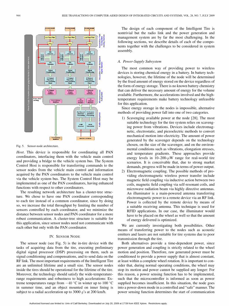
Fig. 5. Sensor-node architecture.
Host. This device is responsible for coordinating all PANcoordinators, interfacing them with the vehicle main controland providing a bridge to the vehicle system bus. The SystemControl Host is responsible for transferring commands to thesensor nodes from the vehicle main control and informationacquired by the PAN coordinators to the vehicle main controlvia the vehicle system bus. The System Control Host may beimplemented as one of the PAN coordinators, having enhancedfunctions with respect to other coordinators.
The resulting network architecture has a cluster-tree struc-ture. We chose to have one PAN coordinator correspondingto each tire instead of a common coordinator, since by doingso, we increase the total throughput by limiting the number ofsensors controlled by each coordinator, and we minimize thedistance between sensor nodes and PAN coordinator for a morerobust communication. A cluster-tree structure is suitable forthis application, since sensor nodes need not communicate witheach other but only with the PAN coordinator.
IV. SENSOR NODE
The sensor node (see Fig. 5) is the in-tire device with thetasks of acquiring data from the tire, executing preliminarydigital signal processor (DSP) processing on them, such assignal conditioning and compensations, and to send data on theRF link. The most important requirements of the Intelligent Tireare an unlimited lifetime and a small size. The sensor nodesinside the tires should be operational for the lifetime of the tire.Moreover, the technology should satisfy the wide-temperature-range requirements and robustness to high accelerations: Ex-treme temperatures range from −40 ◦C in winter up to 100 ◦Cin summer time, and an object mounted on inner lining issubject to a radial acceleration up to 3000 g’s at 200 km/h.
The design of each component of the Intelligent Tire isnontrivial but the radio link and the power generation andmanagement system are by far the most challenging. In thefollowing sections, we describe details of each of the compo-nents together with the challenges to be considered in systemassembly.
A. Power-Supply Subsystem
The most common way of providing power to wirelessdevices is storing chemical energy in a battery. In battery tech-nologies, however, the lifetime of the node will be determinedby the fixed amount of energy stored on the device regardless ofthe form of energy storage. There is no known battery chemistrythat can deliver the necessary amount of energy for the volumeavailable. Furthermore, the accelerations involved and the high-temperature requirements make battery technology unfeasiblefor this application.
Since energy storage in the nodes is impossible, alternativemethods of providing power fall into one of two categories.
1) Scavenging available power at the node [28]. The mostsuitable technology for the tire system relies on scaveng-ing power from vibrations. Devices include electromag-netic, electrostatic, and piezoelectric methods to convertmechanical motion into electricity. The amount of powergenerated by the scavenger depends on the technologychosen, on the size of the scavenger, and on the environ-mental conditions such as vibrations, elongation stresses,and temperature gradients. These approaches provideenergy levels in 10–200-μW range for real-world tirescenarios. It is conceivable that, due to strong marketdemands, progress will be made in terms of power output.
2) Electromagnetic coupling. The possible methods of pro-viding electromagnetic wireless power transfer includemagnetic field coupling via inductive action between twocoils, magnetic field coupling via self-resonant coils, andmicrowave radiation beam via highly directive antennas.An illuminator is a main-powered antenna transferringelectromagnetic power to a remote device via an RF link.Power is collected by the remote device by means ofa suitable receiving antenna. This technique is used forRFID applications. In our case, the illuminator wouldhave to be placed on the wheel as well so that the amountof energy delivered is optimized.
We are currently investigating both possibilities. Othermeans of transferring power to the nodes such as acousticemitters and lasers are not suitable for tire systems due to poortransmission through the tire.
Both alternatives provide a time-dependent power, sincepower generation and coupling is strictly related to the wheelmotion and position. Therefore, raw generated power must beconditioned to provide a power supply that is almost constant,at least within a complete wheel rotation. It is important to con-sider that, during normal operating conditions, the wheel maystop its motion and power cannot be supplied any longer: Forthis reason, a power sensing function has to be implemented,such that the microcontroller is informed as soon as powersupplied becomes insufficient. In this situation, the node goesinto a power-down mode in a controlled and “safe” manner. Thepower sensing function determines the start of communication
Authorized licensed use limited to: Univ of Calif Berkeley. Downloaded on July 20, 2009 at 17:59 from IEEE Xplore. Restrictions apply.

ERGEN et al.: TIRE AS AN INTELLIGENT SENSOR 945
in MAC protocol design, as we will see in Section VI. Fur-thermore, the ultra-low power-consumption constraint suggeststhat acquisition, reception, and transmission phases are keptseparated as much as possible to spread power consumption oneach wheel round and avoid high consumption peaks caused byoverlapping different activities. This places timing constraintson the sensing and communication functions.
B. Sensor- and Acquisition-Path Subsystems
The sensor is a triaxial accelerometer, mounted inside the tireon top of the inner liner, oriented so that the three axes measuresignals in the radial, circumferential (tangential), and lateraldirections with respect to the tire circumference. Therefore, theinput flow to the sensor node consists of three data streams.The requirements that drive the choice of technology for theaccelerometers are reliability and reproducibility, accuracy andresolution, power consumption, size, and cost.
Few available technologies fit all of the requirementslisted above. Stringent power requirements exclude the useof piezoresistive technology. Today’s accelerometers based onpiezoresistive technology have power consumptions in therange of several milliwatts. Even though we may consider acustom-built product that could consume up to a few hundredmicrowatts, this technology intrinsically requires a bias so itwill always be more power hungry than capacitive or piezo-electric devices.
The two main piezoelectric non-microelectromechanical-system (MEMS)-based technologies are crystal and ceramicbased. The latter is somewhat smaller given the same g sensitiv-ity, although less stable in temperature, and with higher processsensitivity spread. This technology is capable of providing thedynamic range of interest, with reliability indexes suitable forour application, and it is intrinsically very low power, providinga charge as an input to the acquisition path satisfying the no-bias-current requirements. However, it is fairly large so it doesnot fit our size requirement.
Current MEMS-based technologies include the followingexamples:
1) piezoelectric technology consisting of deposition of a thinpiezoelectric film of lead titanate onto a MEMS siliconstructure;
2) piezoresistive technology consisting of etching semicon-ducting silicon gauges;
3) capacitive technology.
The capacitive technology is the technology of choice, sinceit is used in airbags with millions of devices shipped annually,having reached a reliability standard that complies with the de-manding requirements of our tire application. It is also very lowcost when manufactured in volume and fits the size constraints.The challenge to deploy this technology is to compensate foran intrinsic spread of process parameters and high dependencesof key design parameters such as sensitivity (millivolts or pico-coulombs per g) and offset to temperature and manufacturingprocess. The challenge of extracting a wide dynamic range withthe required resolution is responsibility of the circuitry thatinterfaces the MEMS device. The accelerometers themselvesare simple devices; all compensations and corrections to thesampled signals are provided by the other components of thesensor node. The acquisition path is responsible for the transfor-
mation of the signal acquired by the accelerometers into digitalsignals, as shown in Fig. 5. The acquisition path provides ananalog section and a digital section.
1) The analog section amplifies and filters the acquiredsignal. Then, analog data are converted and passed to adigital section. Oversampling techniques may be used;thus, signals may be acquired at sampling frequencieshigher than their final sampling rate.
2) The digital section is responsible for signal conditioningfor correcting accelerometer imperfections such as offsetbias and resonant-frequency compensation. Data are sentto a processing chain that provides filtering and decima-tion to the final sampling rate. Automatic-gain-controltechniques may be used to keep the SNR constant, evenat low levels of signal dynamics.
C. Microprocessor Subsystem
A single-core DSP is responsible to manage the communi-cation protocol; all the functions that control the activity of thesensor nodes, such as command execution, system monitoring,and diagnostics; and the following typical DSP functions:
1) estimation and compensation of signal nonlinearity;2) estimation and compensation of crosstalk among the
different accelerometers;3) estimation of bias and offset;4) data compression for reducing the input throughput;5) algorithms required by the communication protocol.
Note that some of these algorithms may be implementedby specialized HW devices to reduce power consumption andincrease performance if product testing will uncover problemsin these areas.
D. Radio Subsystem
The radio subsystem is responsible for the followingfunctions:
1) transforming digital data to be sent to the PAN coor-dinator into analog signals modulated over the desiredtransmission channel;
2) receiving analog data from the transmission channel andtransforming them into baseband digital data.
The radio subsystem consists of an SW driver and an HWtransceiver. The transceiver implements the physical-layer com-ponents, related to channel coding/decoding, modulation andconversions between analog signals to/from digital data, syn-chronization, and generation of events on a fine-grain timescale(bit or chip level). The SW driver implements the MAC layerand higher network layer components and manages all eventsand synchronization requirements at a coarse-grain timescale(frame level). Amplifiers are included in the radio channel toincrease the power of the signal before transmission or beforeprocessing the received signals. This subsystem is expected togive significant contribution to the overall power-consumptionbudget together with the acquisition chain, and for this reason,its design is of paramount importance. We dedicate the nextsection to a detailed description of the solutions adopted.
Authorized licensed use limited to: Univ of Calif Berkeley. Downloaded on July 20, 2009 at 17:59 from IEEE Xplore. Restrictions apply.
946 IEEE TRANSACTIONS ON COMPUTER-AIDED DESIGN OF INTEGRATED CIRCUITS AND SYSTEMS, VOL. 28, NO. 7, JULY 2009
E. System Assembly
The operating conditions of the sensor nodes place hard con-straints on the weight and size of each unit. First, the mass of thesensors must be kept minimal so that it does not affect the tirecharacteristics and the accelerometer signals. In addition, sincethe nodes are to be mounted into the rubber of the tire body,its size must be small (around 1 cm3) so that extra mechanicaldevices do not need to be added to the system package formounting. The small-size requirement directly competes withrequirements needed for the antenna and energy scavenger,where increased size and mass allow better performance. Thesecompeting constraints create many challenges for system opti-mization. Furthermore, the high temperature, centrifugal forces,and mechanical stresses that the system must withstand arenontrivial tasks for system assembly.
V. RADIO SUBSYSTEM
The communication environment in the Intelligent Tiresystem is very harsh. For the uplink transmission, UWBtransmission is preferred to narrowband transmission andspread-spectrum techniques due the presence of severemultipath and lack of line-of-sight (LOS) [22]. In additionto being robust to intersymbol interference due to multipathfading, the UWB systems hide signals below the noise floorcausing little or no interference to existing systems and mitigatethe performance degradation due to narrowband interference.We specifically utilize impulse-based UWB technology due tothe simple transmitter architecture, which makes it ideal for thelow-power high-data-rate uplink transmission from sensor nodeto vehicle. The main drawback is that UWB receiver design ischallenging due to the sensitivity requirements. A low data rateis required for the downlink, so we use narrowband transmis-sion and an ultra-low-power receiver on the sensor nodes.
A. Uplink Communication
UWB technology has emerged in recent years as the idealsolution for low-cost low-power short-range wireless data trans-mission. FCC defines UWB as any radio technology for whichthe emitted signal bandwidth exceeds the lesser of 500 MHzand 20% of the center frequency [15]. In 2002, FCC hasallocated the 3.1–10.6-GHz band for the unlicensed use ofUWB applications; however, these systems must limit energyemission to follow the FCC spectral mask [16] so that nointerference is caused to existing technologies in the band.
To design the UWB system, it is necessary to understandthe transmission channel that operates on the transmittedsignal. There have been studies of typical channels for UWBcommunication systems in indoor and outdoor scenarios. How-ever, these environments are much larger than the wavelengthspresent in the signal, and they are mostly empty. In contrast,the area around the tire is quite different. There are two largereflectors in the immediate vicinity of the node: the wheelrim and the wheel arch of the car’s body. Both of these arevirtually always metal and are curved such that they tend toreflect incident waves back into the area, confining them. Inaddition, the node is inside the tire and must transmit throughthe tire in some way: A true LOS channel is impossible, since
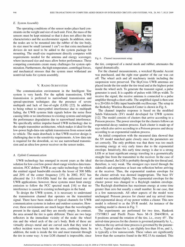
Fig. 6. Channel measurement setup.
the tire, composed of a metal mesh and rubber, attenuates thesignal dramatically.
For the channel measurements, a wrecked Hyundai Accentwas purchased, and the right rear quarter of the car was cutoff. The wheel arch and all machinery inside including thesuspension were preserved. The SkyCross UWB antennas areplaced inside the tire under the tire tread and at the highest pointinside the wheel arch. To generate the transmit signal, a pulsegenerator is used. It is capable of pulses with 100-ps width. Toreceive the signal, the receive antenna is connected to a pulseamplifier through a short cable. The amplified signal is then sentto a 20-GS/s 6-GHz input bandwidth oscilloscope. The setup inthe Berkeley Wireless Research Center is shown in Fig. 6.
The channel impulse response is based on the modifiedSaleh–Valenzuela (SV) model developed for UWB systems[12]. The model consists of clusters that arrive according to aPoisson process. The power envelope for the clusters follows anexponential-decay random process. Each cluster is made up ofrays which also arrive according to a Poisson process and decayaccording to an exponential random process.
An initial comparison with the measured data showed thatthe SV model matched quite closely once the parameters areset correctly. The only problem was that there was too muchincoming energy at very early times due to the exponentialenvelope. Intuitively, this early time energy is due to a strongLOS or at least significant energy traveling in a geometricallystraight line from the transmitter to the receiver. In the case ofthe tire channel, the LOS is probably through the tire thread and,therefore, is very weak. The strongest rays travel through thesidewalls and experience at least one reflection before arrivingat the receiver. Thus, the exponential random envelope forthe cluster arrivals was deemed inappropriate. The base SVmodel was modified slightly. The exponential envelope for thecluster power was changed to a Rayleigh random envelope.The Rayleigh distribution has maximum energy at some timegreater than zero but usually a small number. In our case, thatis a few nanoseconds. All other aspects of the model wereunchanged: Poisson process for cluster and ray arrival timesand exponential decay of ray power within a cluster. This newmodel is referred to as the SV-R model. An instance of theresulting model is shown in Fig. 7.
The experiments are performed for two tires, Hankook175/70R13 and Pirelli Pzero Nero M+S 204/45R16, at8 positions around the rotation of the tire, i.e., every 45◦. Thearrival-time process for the clusters is governed primarily by λc,whereas the ray-arrival-time process is governed by the parame-ter λr. Typical values for λc are slightly less than 10 ns, and λr
is typically a few nanoseconds. These values are significantlylower than the scenarios found in the 802.15.4a standard. This
Authorized licensed use limited to: Univ of Calif Berkeley. Downloaded on July 20, 2009 at 17:59 from IEEE Xplore. Restrictions apply.
ERGEN et al.: TIRE AS AN INTELLIGENT SENSOR 947
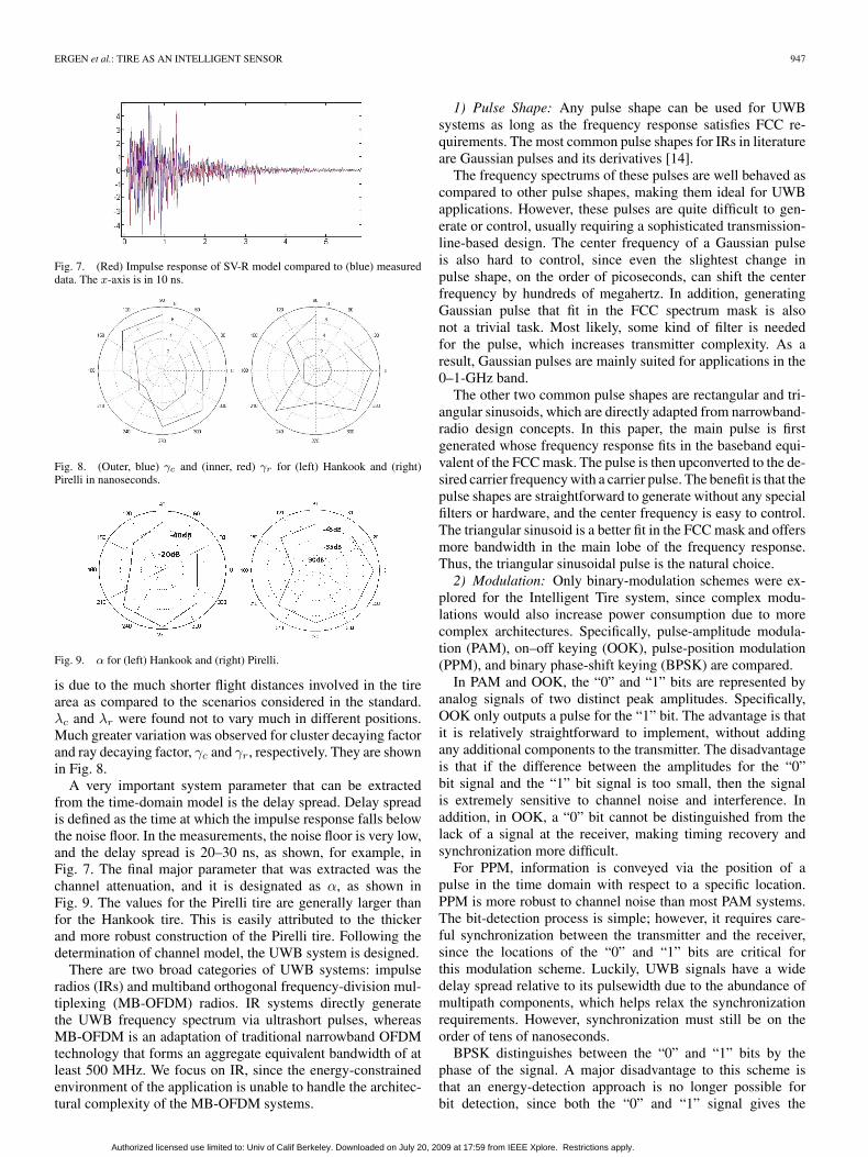
Fig. 7. (Red) Impulse response of SV-R model compared to (blue) measureddata. The x-axis is in 10 ns.
Fig. 8. (Outer, blue) γc and (inner, red) γr for (left) Hankook and (right)Pirelli in nanoseconds.
Fig. 9. α for (left) Hankook and (right) Pirelli.
is due to the much shorter flight distances involved in the tirearea as compared to the scenarios considered in the standard.λc and λr were found not to vary much in different positions.Much greater variation was observed for cluster decaying factorand ray decaying factor, γc and γr, respectively. They are shownin Fig. 8.
A very important system parameter that can be extractedfrom the time-domain model is the delay spread. Delay spreadis defined as the time at which the impulse response falls belowthe noise floor. In the measurements, the noise floor is very low,and the delay spread is 20–30 ns, as shown, for example, inFig. 7. The final major parameter that was extracted was thechannel attenuation, and it is designated as α, as shown inFig. 9. The values for the Pirelli tire are generally larger thanfor the Hankook tire. This is easily attributed to the thickerand more robust construction of the Pirelli tire. Following thedetermination of channel model, the UWB system is designed.
There are two broad categories of UWB systems: impulseradios (IRs) and multiband orthogonal frequency-division mul-tiplexing (MB-OFDM) radios. IR systems directly generatethe UWB frequency spectrum via ultrashort pulses, whereasMB-OFDM is an adaptation of traditional narrowband OFDMtechnology that forms an aggregate equivalent bandwidth of atleast 500 MHz. We focus on IR, since the energy-constrainedenvironment of the application is unable to handle the architec-tural complexity of the MB-OFDM systems.
1) Pulse Shape: Any pulse shape can be used for UWBsystems as long as the frequency response satisfies FCC re-quirements. The most common pulse shapes for IRs in literatureare Gaussian pulses and its derivatives [14].
The frequency spectrums of these pulses are well behaved ascompared to other pulse shapes, making them ideal for UWBapplications. However, these pulses are quite difficult to gen-erate or control, usually requiring a sophisticated transmission-line-based design. The center frequency of a Gaussian pulseis also hard to control, since even the slightest change inpulse shape, on the order of picoseconds, can shift the centerfrequency by hundreds of megahertz. In addition, generatingGaussian pulse that fit in the FCC spectrum mask is alsonot a trivial task. Most likely, some kind of filter is neededfor the pulse, which increases transmitter complexity. As aresult, Gaussian pulses are mainly suited for applications in the0–1-GHz band.
The other two common pulse shapes are rectangular and tri-angular sinusoids, which are directly adapted from narrowband-radio design concepts. In this paper, the main pulse is firstgenerated whose frequency response fits in the baseband equi-valent of the FCC mask. The pulse is then upconverted to the de-sired carrier frequency with a carrier pulse. The benefit is that thepulse shapes are straightforward to generate without any specialfilters or hardware, and the center frequency is easy to control.The triangular sinusoid is a better fit in the FCC mask and offersmore bandwidth in the main lobe of the frequency response.Thus, the triangular sinusoidal pulse is the natural choice.
2) Modulation: Only binary-modulation schemes were ex-plored for the Intelligent Tire system, since complex modu-lations would also increase power consumption due to morecomplex architectures. Specifically, pulse-amplitude modula-tion (PAM), on–off keying (OOK), pulse-position modulation(PPM), and binary phase-shift keying (BPSK) are compared.
In PAM and OOK, the “0” and “1” bits are represented byanalog signals of two distinct peak amplitudes. Specifically,OOK only outputs a pulse for the “1” bit. The advantage is thatit is relatively straightforward to implement, without addingany additional components to the transmitter. The disadvantageis that if the difference between the amplitudes for the “0”bit signal and the “1” bit signal is too small, then the signalis extremely sensitive to channel noise and interference. Inaddition, in OOK, a “0” bit cannot be distinguished from thelack of a signal at the receiver, making timing recovery andsynchronization more difficult.
For PPM, information is conveyed via the position of apulse in the time domain with respect to a specific location.PPM is more robust to channel noise than most PAM systems.The bit-detection process is simple; however, it requires care-ful synchronization between the transmitter and the receiver,since the locations of the “0” and “1” bits are critical forthis modulation scheme. Luckily, UWB signals have a widedelay spread relative to its pulsewidth due to the abundance ofmultipath components, which helps relax the synchronizationrequirements. However, synchronization must still be on theorder of tens of nanoseconds.
BPSK distinguishes between the “0” and “1” bits by thephase of the signal. A major disadvantage to this scheme isthat an energy-detection approach is no longer possible forbit detection, since both the “0” and “1” signal gives the
Authorized licensed use limited to: Univ of Calif Berkeley. Downloaded on July 20, 2009 at 17:59 from IEEE Xplore. Restrictions apply.

948 IEEE TRANSACTIONS ON COMPUTER-AIDED DESIGN OF INTEGRATED CIRCUITS AND SYSTEMS, VOL. 28, NO. 7, JULY 2009
Fig. 10. UWB transmitter.
same energy. Instead, coherent receiver architectures, such asa matched-filter design, must be utilized to track the phase ofthe incoming signals, which complicates receiver architecture,particularly in the presence of an unpredictable channel.
PPM turns out to be the best option for this applicationdue to the simplicity allowed for the receiver architecture androbustness under severe in-band interference and multipath ef-fects. Compared to BPSK, PPM allows the use of noncoherentreceiver architectures such as energy-detection receiver sincewe do not need to track the phase of the incoming signals.Compared to PAM or OOK, PPM is more robust and inherentlycarries timing information from the sensor nodes allowingbetter synchronization with the PAN coordinator.
3) UWB Communication Architecture:Transmitter front end: The uplink radio needs to transmit
at a fairly high data rate, greater than 1 Mb/s, and needs toconsume as little power as possible in the transmitter. Thus,we chose a simple transmitter architecture consisting of a ringoscillator to generate the carrier signal and a pulse controller togenerate the modulated baseband signal, as shown in Fig. 10.
Receiver front end: Power constraints of the sensor nodesallowed us very few options to play with for the transmitter. Thereceiver on the PAN coordinator, however, was not subject tosuch stringent constraints; thus, several architecture alternativeswere feasible. Since the Intelligent Tire system had such asym-metric design constraints, much of the burden for combatingadverse channel effects have been shifted to the receiver side.The goal was to find a receiver architecture that had goodenough sensitivity to capture the UWB signals in the presenceof a harsh channel. In addition, the receiver needs to be robust toin-band interference signals and maintain a relatively consistentperformance. A matched-filter type of design was out of thequestion, since the short duration of UWB signal would placetremendous burden on the analog-to-digital converters at over10-GHz sampling frequency. Although the PAN coordinatoris not as power constrained as the sensor nodes, it is stilllimited. The choices that were evaluated were energy-detectionreceivers at RF and baseband, and correlation receivers at RFand baseband. Scorecard of each of the receiver architectures isshown in Table I. Scores range from 1 to 5, where 5 is the mostsensitive, and 1 is the least.
As expected, energy-detection-based receivers are more sen-sitive to SNR, whereas correlation-based receivers become veryunpredictable in the presence of multipath effects. Overall,
TABLE IUWB RECEIVER SCORECARD
Fig. 11. Energy detection at baseband receiver for UWB detection.
energy-detection at baseband was determined to be the bestdetection algorithm to be used as UWB receiver. UWB signalshave a very rich multipath profile, which makes correlation-based receivers unreliable to use. Although energy-detectionreceivers are prone to interferences from other signals, we hopethat the rich multipath profile of UWB signals will help tomitigate this problem.
The architecture for the uplink receiver, shown in Fig. 11, is amodification of the classical energy-detection receiver that firstdownconverts the incoming signal band and performs energydetection. The incoming signal is first split into two paths anddownconverted in I and Q channels. The two signals are thenfiltered to remove unwanted higher order signals. The resultingsignals are squared and added to produce the final signal. Thissignal is an estimate of the power of the modulating signal thatis not sensitive to the phase of the incoming signal. The signalis finally integrated, and the output (aka chips) is sampled andmade available to the digital baseband section for detection.
Baseband processing: The packet structure and basebandprocessing of the system are based on, but not necessarilycompliant with, IEEE 802.15.4a standard [13] and consist ofthe following processes.
1) Chip synchronization: Using the received preamble, findsthe locations of the incoming pulses to synchronize theanalog front end in preparation for the incoming packet.
2) Despreader: Decodes the incoming chips into bits. Inthe Intelligent Tire system, an 8-b pseudonoise (PN)sequence spreading is used to combat channel effects.
3) Packet detection: Detects the beginning and end of apacket.
4) Error-correcting-codes (ECC) decoding: A Reed–Solomon (RS) coding scheme, and a half-rate convolutionencoder is used to reduce error.
5) Cyclic-redundancy-check (CRC): Parity check for packetvalidity.
The transmitter baseband-processing chain contains the cor-responding components, which are mapped onto a low-powerDSP. The main purpose of the digital baseband blocks in thetransmitter is packet generation (Fig. 12). The packet structureused is inspired by the structure specified in IEEE 802.15.4awith a few modifications to suit our application. First, given Minformation bits from the application, MAC packet is formedby adding MAC header including 1 B for sequence number
Authorized licensed use limited to: Univ of Calif Berkeley. Downloaded on July 20, 2009 at 17:59 from IEEE Xplore. Restrictions apply.

ERGEN et al.: TIRE AS AN INTELLIGENT SENSOR 949
Fig. 12. Receiver-baseband processing.
Fig. 13. Packet structure used for the application with respective number ofsymbols (chips) for each field. We assume M = 32 B for the MAC simulations.
to detect packet losses and 2 B for destination and sourceaddress, and a CRC calculated over both the MAC header andthe data payload for packet validation. The method used was thecommon CRC-8 procedure. Next, following procedures in thestandard, the data are encoded for error correction. The forwarderror-correction encoder consists of an inner RS encoder and anouter convolutional encoder. The RS encoder appends 48 paritybits to the MAC packet and feeds into a half-rate convolutionalencoder, which produces 2(M + 32 + 48) b. The RS encoderuses the following generator polynomial:
g(x) =8∏
k=1
(x + ak)
= x8 + 55x7 + 61x6 + 37x5 + 48x4
+ 47x3 + 20x2 + 6x + 22. (1)
Then, spreading is done by directly mapping each symbol toa constant PN sequence. This differs from the standard, whichemploys a time-hopping spreading technique based on a time-varying PN sequence. The change to direct PN spreading allowsreduced complexity in the transmitter of the sensor nodes andless stringent synchronization requirements for the receiverarchitecture.
The preamble then consists of two fields: SYNC, responsiblefor establishing clock synchronization and timing recovery, andthe start field delimiter (SFD), responsible for denoting thebeginning of an incoming packet to the receiver. Due to thetime constraint of the transmission frame, we use the smallestpreamble size dictated by the standard, i.e., 16 SYNC symbolsand 8 SFD symbols, by default but the length can be adjustedby the PAN coordinator if needed. In addition, since the lengthand the data rate of the packet for our application is fixed, weeliminate the PHY header. The final packet structure used forthe Intelligent Tire system is shown in Fig. 13. An additionaldeviation from the standard’s UWB PHY specifications is themodulation scheme used. As mentioned in Section V-A-2, bi-nary PPM (BPM) is used for this application to reduce receivercomplexity, whereas the standard uses BPM-BPSK modulationfor each two symbols.
UWB simulation: Upon selecting the communication ar-chitecture, we need to extract the performance information ofthe PHY layer into the MAC layer. Since physical implementa-tion is not yet complete, we can only evaluate at the functionallevel. Specifically, the performance is reported in terms of chip-error rate (CER) in Table II. This is the lowest level of ab-straction for the radio before physical implementation. In-bandinterference for the channel was modeled as an additive whiteGaussian noise channel with appropriate SNR assignment. Themultipath profile for the channel is based on the channel modelwe developed. Each result is based on a simulation of 10 000
TABLE IICER SIMULATION RESULTS
TABLE IIIBER SIMULATION RESULTS
TABLE IVPER SIMULATION RESULTS
Fig. 14. Downlink-receiver architecture.
PPM-modulated triangular-sinusoid UWB pulse transmissionsin MATLAB (which takes about 90 min on an AMD Turion X2laptop). Under the assumption of 8-b pseudorandom spreading,the CER to bit-error-rate (BER) result is given in Table III. Afterpacket detection and ECC decoding, the BER to packet-error-rate (PER) result is given in Table IV. The PER informationwill be used in the design of the communication protocol asa measure of the PHY layer performance. Specifically, wedesign a protocol, as will be discussed in Section VI, under theassumed PER of 5%, since channel measurements show thatSNR is around 12 dB for the pulse duration.
B. Downlink Communication
Downlink transmission from PAN coordinator to tire sensornodes is used primarily to transmit minimal information forMAC scheduling, as detailed in Section VI. Due to the low-data-rate requirements, narrowband communication is used.Furthermore, we apply an ultra-low-power radio design dueto power restrictions of the sensor nodes. The power of thedownlink receiver needs to be under 100 μW. The only viablearchitecture to demonstrate this low of a receiver power isbased on energy-detection [18]. Other radio receivers havebeen demonstrated with system powers on the order of a fewhundred microwatts. The key to using less than 100 μW is theelimination of the local oscillator and the use of a low-powerMEMS-based bulk-acoustic-wave (BAW) front-end filter. Thisinfluences most other decisions in the receiver design and yieldsthe basic architecture, as shown in Fig. 14. Its basic operationconsists of determining whether RF energy exists in a givenfrequency band. The signal is coded for interference mitigation.
The operation of the receive chain is as follows. The in-coming signal is first filtered so that only the narrowband ofinterest is admitted. The performance of this BAW filter is
Authorized licensed use limited to: Univ of Calif Berkeley. Downloaded on July 20, 2009 at 17:59 from IEEE Xplore. Restrictions apply.
950 IEEE TRANSACTIONS ON COMPUTER-AIDED DESIGN OF INTEGRATED CIRCUITS AND SYSTEMS, VOL. 28, NO. 7, JULY 2009
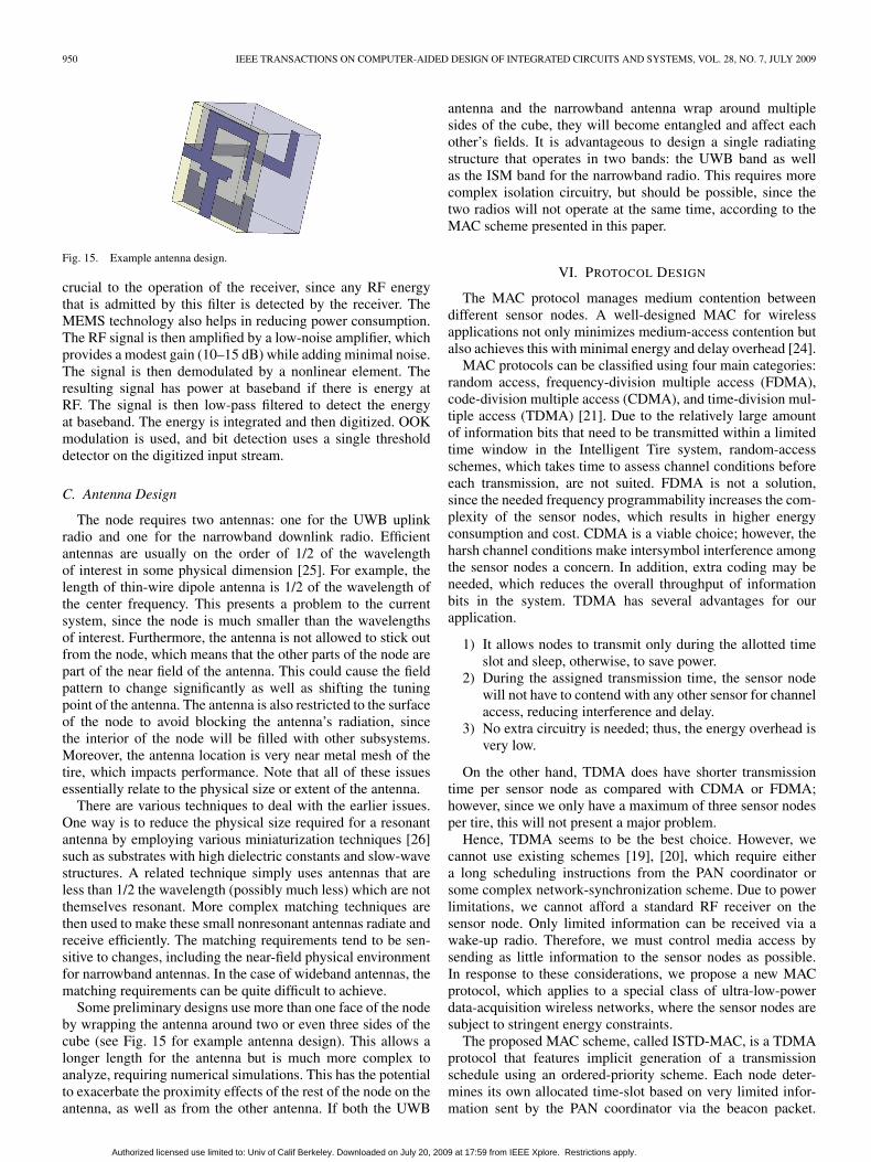
Fig. 15. Example antenna design.
crucial to the operation of the receiver, since any RF energythat is admitted by this filter is detected by the receiver. TheMEMS technology also helps in reducing power consumption.The RF signal is then amplified by a low-noise amplifier, whichprovides a modest gain (10–15 dB) while adding minimal noise.The signal is then demodulated by a nonlinear element. Theresulting signal has power at baseband if there is energy atRF. The signal is then low-pass filtered to detect the energyat baseband. The energy is integrated and then digitized. OOKmodulation is used, and bit detection uses a single thresholddetector on the digitized input stream.
C. Antenna Design
The node requires two antennas: one for the UWB uplinkradio and one for the narrowband downlink radio. Efficientantennas are usually on the order of 1/2 of the wavelengthof interest in some physical dimension [25]. For example, thelength of thin-wire dipole antenna is 1/2 of the wavelength ofthe center frequency. This presents a problem to the currentsystem, since the node is much smaller than the wavelengthsof interest. Furthermore, the antenna is not allowed to stick outfrom the node, which means that the other parts of the node arepart of the near field of the antenna. This could cause the fieldpattern to change significantly as well as shifting the tuningpoint of the antenna. The antenna is also restricted to the surfaceof the node to avoid blocking the antenna’s radiation, sincethe interior of the node will be filled with other subsystems.Moreover, the antenna location is very near metal mesh of thetire, which impacts performance. Note that all of these issuesessentially relate to the physical size or extent of the antenna.
There are various techniques to deal with the earlier issues.One way is to reduce the physical size required for a resonantantenna by employing various miniaturization techniques [26]such as substrates with high dielectric constants and slow-wavestructures. A related technique simply uses antennas that areless than 1/2 the wavelength (possibly much less) which are notthemselves resonant. More complex matching techniques arethen used to make these small nonresonant antennas radiate andreceive efficiently. The matching requirements tend to be sen-sitive to changes, including the near-field physical environmentfor narrowband antennas. In the case of wideband antennas, thematching requirements can be quite difficult to achieve.
Some preliminary designs use more than one face of the nodeby wrapping the antenna around two or even three sides of thecube (see Fig. 15 for example antenna design). This allows alonger length for the antenna but is much more complex toanalyze, requiring numerical simulations. This has the potentialto exacerbate the proximity effects of the rest of the node on theantenna, as well as from the other antenna. If both the UWB
antenna and the narrowband antenna wrap around multiplesides of the cube, they will become entangled and affect eachother’s fields. It is advantageous to design a single radiatingstructure that operates in two bands: the UWB band as wellas the ISM band for the narrowband radio. This requires morecomplex isolation circuitry, but should be possible, since thetwo radios will not operate at the same time, according to theMAC scheme presented in this paper.
VI. PROTOCOL DESIGN
The MAC protocol manages medium contention betweendifferent sensor nodes. A well-designed MAC for wirelessapplications not only minimizes medium-access contention butalso achieves this with minimal energy and delay overhead [24].
MAC protocols can be classified using four main categories:random access, frequency-division multiple access (FDMA),code-division multiple access (CDMA), and time-division mul-tiple access (TDMA) [21]. Due to the relatively large amountof information bits that need to be transmitted within a limitedtime window in the Intelligent Tire system, random-accessschemes, which takes time to assess channel conditions beforeeach transmission, are not suited. FDMA is not a solution,since the needed frequency programmability increases the com-plexity of the sensor nodes, which results in higher energyconsumption and cost. CDMA is a viable choice; however, theharsh channel conditions make intersymbol interference amongthe sensor nodes a concern. In addition, extra coding may beneeded, which reduces the overall throughput of informationbits in the system. TDMA has several advantages for ourapplication.
1) It allows nodes to transmit only during the allotted timeslot and sleep, otherwise, to save power.
2) During the assigned transmission time, the sensor nodewill not have to contend with any other sensor for channelaccess, reducing interference and delay.
3) No extra circuitry is needed; thus, the energy overhead isvery low.
On the other hand, TDMA does have shorter transmissiontime per sensor node as compared with CDMA or FDMA;however, since we only have a maximum of three sensor nodesper tire, this will not present a major problem.
Hence, TDMA seems to be the best choice. However, wecannot use existing schemes [19], [20], which require eithera long scheduling instructions from the PAN coordinator orsome complex network-synchronization scheme. Due to powerlimitations, we cannot afford a standard RF receiver on thesensor node. Only limited information can be received via awake-up radio. Therefore, we must control media access bysending as little information to the sensor nodes as possible.In response to these considerations, we propose a new MACprotocol, which applies to a special class of ultra-low-powerdata-acquisition wireless networks, where the sensor nodes aresubject to stringent energy constraints.
The proposed MAC scheme, called ISTD-MAC, is a TDMAprotocol that features implicit generation of a transmissionschedule using an ordered-priority scheme. Each node deter-mines its own allocated time-slot based on very limited infor-mation sent by the PAN coordinator via the beacon packet.
Authorized licensed use limited to: Univ of Calif Berkeley. Downloaded on July 20, 2009 at 17:59 from IEEE Xplore. Restrictions apply.
ERGEN et al.: TIRE AS AN INTELLIGENT SENSOR 951
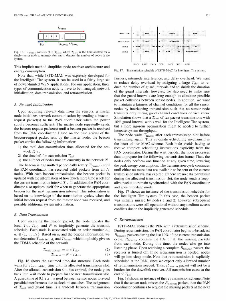
Fig. 16. Tframe consists of n Tslot, where Tslot is the time allotted for asingle-sensor node to transmit data and n denotes the number of nodes in thesystem.
This implicit method simplifies node receiver architecture andenergy consumption.
Note that, while ISTD-MAC was expressly developed forthe Intelligent Tire system, it can be used in a fairly large setof power-limited WSN applications. For our application, threetypes of communication activity have to be managed: networkinitialization, data transmission, and retransmission.
A. Network Initialization
Upon acquiring relevant data from the sensors, a masternode initializes network communication by sending a beacon-request packet(s) to the PAN coordinator when the powersupply becomes sufficient. The master node repeatedly sendsthe beacon request packet(s) until a beacon packet is receivedfrom the PAN coordinator. Based on the time arrival of thebeacon-request packet sent by the master node, the beaconpacket carries the following information:
1) the total data-transmission time allocated for the net-work Ttx0;
2) the time left for transmission Ttx;3) the number of nodes that are currently in the network N .The beacon is transmitted periodically (every Tframe) until
the PAN coordinator has received valid packets from all Nnodes. With each beacon transmission, the beacon packet isupdated with the information of how much more time is left forthe current transmission interval Ttx. In addition, the PAN coor-dinator also updates itself for when to generate the appropriatebeacon for the next transmission interval. This information isbased on its knowledge of the transmission cycles, when theinitial beacon request from the master node was received, andpossible additional system information.
B. Data Transmission
Upon receiving the beacon packet, the node updates thelocal Ttx, Ttx0, and N to implicitly generate the transmitschedule. Each node is associated with an order number ai,ai ∈ {1, . . . , N}. Based on ai and the beacon information, wecan determine Twait initiali and Tframe, which implicitly give usthe TDMA schedule of the network
Twait initiali = ai ∗ Tslot (2)Tframe =N ∗ Tslot. (3)
Fig. 16 shows the assumed time-slot structure. Each nodewaits for Twait initiali time until its allocated transmission slot.After the allotted transmission slot has expired, the node goesback into wait mode to prepare for the next transmission slot.A guard time of 0.1 Tslot is used between sensor nodes to avoidpossible interferences due to clock mismatches. The assignmentof Tslot and guard time is a tradeoff between transmission
Fig. 17. Transmission schedule of ISTD-MAC for Intelligent Tire system.
fairness, internode interference, and delay overhead. We wantto reduce delay overhead by assigning a large Tslot to re-duce the number of guard intervals and to shrink the durationof the guard intervals; however, we also need to make surethat the guard intervals are long enough to eliminate possiblepacket collisions between sensor nodes. In addition, we wantto maintain a fairness of channel conditions for all the sensornodes by interleaving transmission such that no sensor nodetransmits only during good channel conditions or vice versa.Simulation shows that a Tslot of ten packet transmissions with10% guard interval works well for the Intelligent Tire system,but a more rigorous optimization might be needed to furtherincrease system throughput.
The node waits Tframe after each transmission slot beforetransmitting again. This automatic-scheduling mechanism isthe heart of our MAC scheme. Each node avoids having toreceive complex scheduling instructions explicitly from thePAN coordinator. During the wait periods, the node processesdata to prepare for the following transmission frame. Thus, thenodes only perform one function at any given time, loweringthe peak energy consumption. The transmission cycle continuesuntil either no more data are available to be sent or the currenttransmission interval has expired. If there are no data to transmitduring the allocated transmission slot, the node sends a keep-alive packet to remain synchronized with the PAN coordinatorand goes into sleep mode.
Fig. 17 shows an instance of the transmission schedule forthe Intelligent Tire system. In this case, the beacon packetwas initially missed by nodes 1 and 2; however, subsequenttransmissions were still operational without any medium-accessconflicts due to the implicitly generated schedule.
C. Retransmission
ISTD-MAC reduces the PER with a retransmission scheme.During retransmission, the PAN coordinator begins to broadcastRbeacon packets during the last 10% of the current transmissioncycle. Rbeacon contains the IDs of all the missing packetsfrom each node. During this time, the nodes also go intolistening phase. Upon receiving a complete Rbeacon packet, thereceiver is turned off. If no retransmission is needed, nodeswill go into sleep mode. Note that retransmission is explicitlyscheduled at the PAN, since we expect only a limited numberof retransmissions needed. Thus, Rbeacon packet will not be aburden for the downlink receiver. All transmission cease at theend of Ttx0.
Fig. 18 shows an instance of the retransmission scheme. Notethat if the sensor node misses the Rbeacon packet, then the PANcoordinator continues to request the missing packets at the next
Authorized licensed use limited to: Univ of Calif Berkeley. Downloaded on July 20, 2009 at 17:59 from IEEE Xplore. Restrictions apply.

952 IEEE TRANSACTIONS ON COMPUTER-AIDED DESIGN OF INTEGRATED CIRCUITS AND SYSTEMS, VOL. 28, NO. 7, JULY 2009
Fig. 18. Retransmission-scheduling scheme.
Fig. 19. MAC CFSM model.
retransmission frame, as long as the total transmission time Ttx0
has not expired.
D. MAC Analysis
To verify the functionality of ISTD-MAC, we created, inSimulink, a codesign finite-state machine (CFSM) [17], whichis a globally asynchronous–locally synchronous model of com-putation. As shown in Fig. 19, the sensor nodes and PANcoordinator are modeled as FSMs, each synchronized to a localclock. Operations in sensor nodes are annotated with estimatedenergy-consumption figures. To simulate real operation con-ditions, the communication between sensor nodes and PANcoordinator is modeled as an asynchronous process. Takinginput from the triggering algorithm, as well as extracted PHYlayer nonidealities such as PER, clock jitter, and clock skew,the MAC model generates a stream of received packets forvalidation of the protocol and an energy profile for each of thesensor nodes.
Fig. 20 shows the PER performance of the system (i.e.,cumulative for all three sensors), with and without packetretransmission as a function of single-sensor PER. The sim-ulation setup assumed 1-Mb/s data rate, 40-B packet size,10 packet transmissions per allocated time slot per sensor,18 full wheel rotations with varying velocities, and triggeringdata from actual sensor data. Without retransmission, the PERof the overall system is roughly the same as the nominalsingle-sensor PER. No additional packet errors were addedto the system; therefore, we can conclude that no mediumcontentions (i.e., packet collisions) between the sensor nodesoccurred. With retransmission, the system PER dropped to wellbelow 1%, with a maximum PER reduction of 95%, simply byallocating 10% of the transmission window for retransmission.
Fig. 20. System PER versus nominal PER plot from MAC simulations.
Fig. 21. MAC energy profile for nodes 1, 2, and 3.
Fig. 21 shows the energy profile of the sensor nodes atdifferent intervals of operation. With the exception of networkinitialization in the master node, energy consumption is keptbelow 175 nJ per packet time (320 μs) at any given time.This is roughly 55% of the total power available, assuming a1-mW power source. The rest the energy can be stored for otheroperations of the sensor node. Although the energy profiles arebased on preliminary energy estimation, we can infer that theMAC protocol spreads the sensor operation through time so thatthe peak power consumption is kept low. Thus, ISTD-MAC isable to virtually eliminate medium contention while still stayingwithin the assumed energy budget of 1 mW.
VII. DESIGN-SPACE-EXPLORATION STRATEGY
As discussed previously, the design of the Intelligent Tiresystem requires expertise in multiple engineering disciplines,including integrated-circuit design, communications, signalprocessing, real-time software design, antenna design, energyscavenging, and system assembly. In addition, the harsh operat-ing conditions require aggressive design-space exploration, notonly for each individual component but also for the system as awhole. The design methodology we adopted is platform-baseddesign (PBD) [27]. The methodology is a meet-in-the-middleprocess that allows for systematic design-space exploration,where successive refinements of the application specificationsmeet various abstractions of potential implementations. Theorthogonalization of concerns is key to PBD. By separat-ing application functionality from architecture implementation,PBD can be utilized to design very complex heterogeneoussystems.
Authorized licensed use limited to: Univ of Calif Berkeley. Downloaded on July 20, 2009 at 17:59 from IEEE Xplore. Restrictions apply.
ERGEN et al.: TIRE AS AN INTELLIGENT SENSOR 953
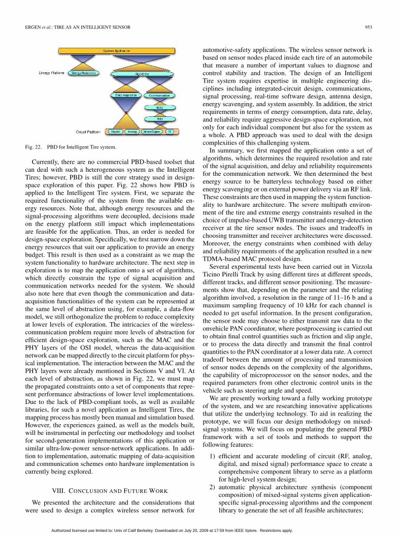
Fig. 22. PBD for Intelligent Tire system.
Currently, there are no commercial PBD-based toolset thatcan deal with such a heterogeneous system as the IntelligentTires; however, PBD is still the core strategy used in design-space exploration of this paper. Fig. 22 shows how PBD isapplied to the Intelligent Tire system. First, we separate therequired functionality of the system from the available en-ergy resources. Note that, although energy resources and thesignal-processing algorithms were decoupled, decisions madeon the energy platform still impact which implementationsare feasible for the application. Thus, an order is needed fordesign-space exploration. Specifically, we first narrow down theenergy resources that suit our application to provide an energybudget. This result is then used as a constraint as we map thesystem functionality to hardware architecture. The next step inexploration is to map the application onto a set of algorithms,which directly constrain the type of signal acquisition andcommunication networks needed for the system. We shouldalso note here that even though the communication and data-acquisition functionalities of the system can be represented atthe same level of abstraction using, for example, a data-flowmodel, we still orthogonalize the problem to reduce complexityat lower levels of exploration. The intricacies of the wireless-communication problem require more levels of abstraction forefficient design-space exploration, such as the MAC and thePHY layers of the OSI model, whereas the data-acquisitionnetwork can be mapped directly to the circuit platform for phys-ical implementation. The interaction between the MAC and thePHY layers were already mentioned in Sections V and VI. Ateach level of abstraction, as shown in Fig. 22, we must mapthe propagated constraints onto a set of components that repre-sent performance abstractions of lower level implementations.Due to the lack of PBD-compliant tools, as well as availablelibraries, for such a novel application as Intelligent Tires, themapping process has mostly been manual and simulation based.However, the experiences gained, as well as the models built,will be instrumental in perfecting our methodology and toolsetfor second-generation implementations of this application orsimilar ultra-low-power sensor-network applications. In addi-tion to implementation, automatic mapping of data-acquisitionand communication schemes onto hardware implementation iscurrently being explored.
VIII. CONCLUSION AND FUTURE WORK
We presented the architecture and the considerations thatwere used to design a complex wireless sensor network for
automotive-safety applications. The wireless sensor network isbased on sensor nodes placed inside each tire of an automobilethat measure a number of important values to diagnose andcontrol stability and traction. The design of an IntelligentTire system requires expertise in multiple engineering dis-ciplines including integrated-circuit design, communications,signal processing, real-time software design, antenna design,energy scavenging, and system assembly. In addition, the strictrequirements in terms of energy consumption, data rate, delay,and reliability require aggressive design-space exploration, notonly for each individual component but also for the system asa whole. A PBD approach was used to deal with the designcomplexities of this challenging system.
In summary, we first mapped the application onto a set ofalgorithms, which determines the required resolution and rateof the signal acquisition, and delay and reliability requirementsfor the communication network. We then determined the bestenergy source to be batteryless technology based on eitherenergy scavenging or on external power delivery via an RF link.These constraints are then used in mapping the system function-ality to hardware architecture. The severe multipath environ-ment of the tire and extreme energy constraints resulted in thechoice of impulse-based UWB transmitter and energy-detectionreceiver at the tire sensor nodes. The issues and tradeoffs inchoosing transmitter and receiver architectures were discussed.Moreover, the energy constraints when combined with delayand reliability requirements of the application resulted in a newTDMA-based MAC protocol design.
Several experimental tests have been carried out in VizzolaTicino Pirelli Track by using different tires at different speeds,different tracks, and different sensor positioning. The measure-ments show that, depending on the parameter and the relatingalgorithm involved, a resolution in the range of 11–16 b and amaximum sampling frequency of 10 kHz for each channel isneeded to get useful information. In the present configuration,the sensor node may choose to either transmit raw data to theonvehicle PAN coordinator, where postprocessing is carried outto obtain final control quantities such as friction and slip angle,or to process the data directly and transmit the final controlquantities to the PAN coordinator at a lower data rate. A correcttradeoff between the amount of processing and transmissionof sensor nodes depends on the complexity of the algorithms,the capability of microprocessor on the sensor nodes, and therequired parameters from other electronic control units in thevehicle such as steering angle and speed.
We are presently working toward a fully working prototypeof the system, and we are researching innovative applicationsthat utilize the underlying technology. To aid in realizing theprototype, we will focus our design methodology on mixed-signal systems. We will focus on populating the general PBDframework with a set of tools and methods to support thefollowing features:
1) efficient and accurate modeling of circuit (RF, analog,digital, and mixed signal) performance space to create acomprehensive component library to serve as a platformfor high-level system design;
2) automatic physical architecture synthesis (componentcomposition) of mixed-signal systems given application-specific signal-processing algorithms and the componentlibrary to generate the set of all feasible architectures;
Authorized licensed use limited to: Univ of Calif Berkeley. Downloaded on July 20, 2009 at 17:59 from IEEE Xplore. Restrictions apply.
954 IEEE TRANSACTIONS ON COMPUTER-AIDED DESIGN OF INTEGRATED CIRCUITS AND SYSTEMS, VOL. 28, NO. 7, JULY 2009
3) global (architecture and circuit configuration) system op-timization to determine optimal system design for thegiven application.
These tools and methods will help in determining to bestmapping of the Intelligent Tire system’s signal acquisition andcommunication functionalities onto the set of available circuitcomponents to minimize overall system cost.
REFERENCES
[1] T. Schrüllkamp, H. Goertz, and T. Hüsemann, “Development of an intelli-gent tire—Experiences from the APOLLO project,” in Intell. Tire Technol.Conf., Frankfurt, Germany, Nov. 2005.
[2] J. Yi, “A piezo-sensor-based ‘smart tire’ system for mobile robots andvehicles,” IEEE/ASME Trans. Mechatronics, vol. 13, no. 1, pp. 95–103,Feb. 2008.
[3] A. Todoroki, S. Miyatani, and Y. Shimamura, “Wireless strain monitoringusing electrical capacitance change of tire with oscillating circuit,” SmartMater. Struct., vol. 12, no. 3, pp. 403–409, Jun. 2003.
[4] N. Robinson, III and J. H. Matthews, “Remote tire pressure monitoringsystem employing coded tire identification and radio frequency transmis-sion and enabling recalibration upon tire rotation or replacement,” Patent:5 838 229, Nov. 17, 1998.
[5] K. E. Mattson, L. W. Hamm, W. K. Cotton, R. A. Stewart, M. A. Uleski,R. B. Belden, and M. A. Peterson, “Tire pressure monitor system withside entry pressure port,” Patent: 7 377 156, May 27, 2008.
[6] J. P. Robillard, B. S. Honeck, J. R. Geschke, and M. J. Suman, “Tiremonitoring system,” Patent: 6 259 361, Jul. 10, 2001.
[7] R. Behringer and N. Muller, “Autonomous road vehicle guidance fromautobahnen to narrow curves,” IEEE Trans. Robot. Autom., vol. 14, no. 5,pp. 810–815, Oct. 1998.
[8] A. Nepote, P. Pierre, T. Varpula, A. Rautiainen, and K. Jaakkola, “The in-telligent tire: Acceleration sensors data acquisition,” in SAE World Congr.,Apr. 2005, pp. 59–66.
[9] World Health Organization, World Report on Road Traffic InjuryPrevention, 2004.
[10] S. Muller, M. Uchanski, and K. Hedrick, “Estimation of the maximumtire–road friction coefficient,” Trans. ASME, J. Dyn. Syst. Meas. Control,vol. 125, no. 4, pp. 607–617, Dec. 2003.
[11] F. Gustafsson, “Slip-based tire–road friction estimation,” Automatica,vol. 33, no. 6, pp. 1087–1099, Jun. 1997.
[12] A. F. Molisch, K. Balakrishnan, D. Cassioli, C.-C. Chong, S. Emami,A. Fort, J. Karedal, J. Kunisch, H. Schantz, and K. Siwiak, “A com-prehensive model for ultrawideband propagation channels,” in IEEEGLOBECOM, Nov. 2005, vol. 6, pp. 3648–3653.
[13] IEEE 802.15.TG4a Official Web Page. [Online]. Available: http://www.ieee801.org/15/pub/tg4a.html
[14] H. Sheng, P. Orlik, A. Haimovich, L. C. Cimini, Jr., and J. Zhang, “Onthe spectral and power requirements for ultra-wideband transmission,” inIEEE Int. Conf. Commun, 2003, pp. 738–742.
[15] V. Somayazulu, J. R. Forester, and S. Roy, “Design challenges for veryhigh data rate UWB systems,” in Conf. Rec. 36th Asilomar Conf. Signals,Syst., Comput., Nov. 2002, vol. 1, pp. 717–721.
[16] X. Shen, M. Guizani, R. Qiu, and T. Le-Ngoc, Ultra-Wideband WirelessCommunications and Networks. Hoboken, NJ: Wiley, 2006.
[17] F. Balarin, H. Hseih, A. Jurecska, L. Lavagno, and A. Sangiovanni-Vincentelli, “Formal verification of embedded systems based on CFSMnetworks,” in Proc. 33rd Annu. Conf. Des. Autom., 1996, pp. 568–571.
[18] N. Pletcher, S. Gambini, and J. Rabaey, “A 65 uW, 1.9 GHz RF to digitalbaseband wakeup receiver for wireless sensor nodes,” in Proc. CustomIntegr. Circuits Conf., San Jose, CA, Sep. 2007, pp. 539–542.
[19] D. Networks, Technical Overview of Time Synchronized Mesh Protocol(TSMP), Jun. 2006. document number: 025-0003-01.
[20] S. Coleri and P. Varaiya, “PEDAMACS: Power efficient and delayaware medium access protocol for sensor networks,” IEEE Trans. MobileComput., vol. 5, no. 7, pp. 920–930, Jul. 2006.
[21] J. G. Proakis, Digital Communications, 4th ed. New York: McGraw-Hill, 2001.
[22] A. Goldsmith, Wireless Communications. Cambridge, U.K.: CambridgeUniv. Press, 2005.
[23] A. V. Oppenheim and R. W. Schafer, Discrete-Time Signal Processing.Englewood Cliffs, NJ: Prentice-Hall, 1999.
[24] M. G. D. Benedetto and G. Giancola, Understanding Ultra Wide BandRadio Fundamentals. Englewood Cliffs, NJ: Prentice-Hall, 2004.
[25] C. Balanis, Antenna Theory: Analysis and Design, 3rd ed. Hoboken, NJ:Wiley, 2005.
[26] P. Bhartia, I. Bahl, R. Garg, and A. Ittipiboon, Microstrip Antenna DesignHandbook. Norwood, MA: Artech House, 2000.
[27] A. Sangiovanni-Vincentelli, L. Carloni, F. D. Bernardinis, and M. Sgroi,“Benefits and challenges for platform-based design,” in Proc. 41st Annu.DAC, 2004, pp. 409–414.
[28] S. Roundy, M. Strasser, and P. K. Wright, Powering Ambient IntelligentNetworks. Berlin, Germany: Springer-Verlag, Dec. 2005, pp. 271–299.
Sinem Coleri Ergen (S’98–M’07) received the B.S.degree in electrical and electronics engineering fromBilkent University, Ankara, Turkey, in 2000 and theM.S. and Ph.D. degrees in electrical engineering andcomputer sciences from the University of California,Berkeley, Berkeley, in 2002 and 2005, respectively.
Since July 2006, she has been a Research Sci-entist with the Wireless Sensor Networks BerkeleyLaboratory, Berkeley, which is under the sponsorshipof Pirelli and Telecom Italia. Her research interestsinclude wireless communications and networking,
collaborative signal processing, and embedded systems.Dr. Ergen was the recipient of the Regents Fellowship from the University of
California, Berkeley, in 2000, and the Bilkent University Full Scholarship fromBilkent University in 1995.
Alberto Sangiovanni-Vincentelli (F’82) receivedthe “Dottore in Ingegneria” degree (summa cumlaude) in electrical engineering and computer sci-ence from the Politecnico di Milano, Milano, Italy,in 1971.
From 1980 to 1981, he was a Visiting Scientistin the Mathematical Sciences Department, IBM T. J.Watson Research Center, Yorktown Heights, NY. In1987, he was a Visiting Professor at MassachusettsInstitute of Technology, Cambridge. He has helda number of Visiting Professor positions at Italian
Universities, including Politecnico di Torino, Torino, Italy; Universita’ diRoma, La Sapienza, Rome, Italy; Universita’ di Roma, Tor Vergata, Rome;Universita’ di Pavia, Pavia, Italy; and Universita’ di Pisa, Scuola di Sant’Anna,Pisa, Italy. He was a cofounder of Cadence and Synopsys, the two leadingcompanies in the area of electronic design automation. He is currently theChief Technology Adviser of Cadence. He is a member of the Board ofDirectors of Cadence and the Chair of its Technology Committee, UPEK,a company he helped spinning off from ST Microelectronics, Sonics, andAccent, an ST Microelectronics–Cadence joint venture he helped founding.He was a member of the HP Strategic Technology Advisory Board. He iscurrently a member of the Science and Technology Advisory Board of GeneralMotors and of the Scientific Council of the Tronchetti Provera Foundationand of the Snaidero Foundation. He is currently the Edgar L. and HaroldH. Buttner Chair of Electrical Engineering and Computer Sciences with theDepartment of Electrical Engineering and Computer Science, University ofCalifornia, Berkeley, Berkeley, where he has been on the faculty since 1976.He consulted for many companies including Bell Laboratories, IBM, Intel,United Technologies Corporation, COMAU, Magneti Marelli, Pirelli, BMW,Daimler–Chrysler, Fujitsu, Kawasaki Steel, Sony, ST, United TechnologiesCorporation, and Hitachi. He was an Advisor to the Singapore Governmentfor microelectronics and new ventures. He consulted for Greylock Venturesand for Vertex Investment Venture Capital funds. He is a member of theAdvisory Board of Walden International, Sofinnova, and Innogest VentureCapital Funds and a member of the Investment Committee of a novel VC Fund,Atlante Ventures, by Banca Intesa/San Paolo. He is the founder and ScientificDirector of the Project on Advanced Research on Architectures and Designof Electronic Systems, a European Group of Economic Interest supported byCadence, Magneti–Marelli, and ST Microelectronics. He is a member of theAdvisory Board of the Lester Center for Innovation of the Haas School ofBusiness and of the Center for Western European Studies and is a memberof the Berkeley Roundtable of the International Economy. He is a member ofthe High-Level Group, of the Steering Committee, of the Governing Board,and of the Public Authorities Board of the EU Artemis Joint TechnologyInitiative. He is a member of the Scientific Council of the Italian NationalScience Foundation. He is an author of over 800 papers, 15 books, and 3 patentsin the area of design tools and methodologies, large-scale systems, embeddedsystems, hybrid systems, and innovation.
Authorized licensed use limited to: Univ of Calif Berkeley. Downloaded on July 20, 2009 at 17:59 from IEEE Xplore. Restrictions apply.

ERGEN et al.: TIRE AS AN INTELLIGENT SENSOR 955
Prof. Sangiovanni-Vincentelli was the recipient of the Distinguished Teach-ing Award of the University of California in 1981. He was also the recipientof the worldwide 1995 Graduate Teaching Award of the IEEE (a TechnicalField Award for “inspirational teaching of graduate students”). In 2002, hewas the recipient of the Aristotle Award of the Semiconductor ResearchCorporation. He was the recipient of numerous research awards, includingthe Guillemin–Cauer Award (1982–1983), the Darlington Award (1987–1988)of the IEEE for the best paper bridging theory and applications, and twoawards for the best paper published in the IEEE TRANSACTIONS ON CIRCUITS
AND SYSTEMS and IEEE TRANSACTIONS ON COMPUTER-AIDED DESIGN
OF INTEGRATED CIRCUITS AND SYSTEMS. He was also the recipient of fivebest paper awards and one best presentation awards at the Design AutomationConference and other best paper awards at the Real-Time Systems Symposiumand the VLSI Conference. In 2001, he was the recipient of the Kaufman Awardof the Electronic Design Automation Council for “pioneering contributions toEDA.” In 2008, he was the recipient of the IEEE/RSE Wolfson James ClerkMaxwell Medal “for groundbreaking contributions that have had an exceptionalimpact on the development of electronics and electrical engineering or relatedfields” with the following citation: “For pioneering innovation and leadership inelectronic design automation that have enabled the design of modern electronicssystems and their industrial implementation.” He is a member of the NationalAcademy of Engineering, which is the highest honor bestowed upon a U.S.Engineer, since 1998.
Xuening Sun (M’02) received the B.S.E.E. degree(with highest honors) from the University of Texasat Austin, Austin, in 2004 and the M.S. degree fromthe University of California, Berkeley, Berkeley, in2007, where he is currently working toward the Ph.D.degree in the Department of Electrical Engineeringand Computer Science.
In 2005, he was with IBM, Austin, where he wasa Design Engineer for the zSeries server processorfamily before pursuing graduate studies in electronicdesign automation. In the summers of 2006 and
2007, he was a Research Intern at the Pirelli/Telecom Italia Wireless SensorNetworks Laboratory, Berkeley, where he was involved in ultrawidebandsystem modeling and MAC protocol design. His research interests includeelectronic-system-level design methodologies, with a special interest in system-level composition of analog/RF circuits.
Riccardo Tebano received the Laurea degree inphysics from the Università degli Studi di Milano,Milano, Italy, in 1998 and the Ph.D. degree from theUniversità degli Studi di Milano-Bicocca, Milano,in 2001.
He is currently with the Tyre System and VehicleDynamics Department, Pirelli Tyre S.p.A., Milano,Italy.
Sayf Alalusi received the B.S., M.S., and Ph.D. degrees from the University ofCalifornia, Berkeley, in 1998, 2001, and 2005, respectively.
He first worked for HRL Laboratories Malibu, CA, on many diverse researchtasks. He then joined the Wireless Sensor Networks Berkeley Laboratory,Berkeley, where he worked on low-power radios and wireless energy transferprojects for Pirelli’s Smart Tire initiative. He is currently with TransRobotics,an early-stage start-up company in the San Francisco Bay Area, Hayward, CA,specializing in industrial sensing and automation.
Giorgio Audisio received the degree in electricalengineering from the Politecnico di Torino, Torino,Italy, in 1985.
He started his professional career with the Tele-com Research Institute. In 1987, he joined FiatAuto, where he was appointed Head of the Electricaland Electronic Design Centre in 1997. During theseyears, his team redesigned all the electrical and elec-tronic architectures of Fiat, Alfa, and Lancia modelswith a dramatic improvement of reliability and costreduction. After a period as Director of Innovation,
he was appointed as Deputy Director of the Electrical and Electronic Compe-tence Area, where he led the joint project with Microsoft for the developmentof a new telematics platform (Blue&Me) which is now deployed in all FiatAuto and Iveco vehicles. In 2005, he joined Pirelli Tyres S.p.A., Milano, Italy,as Chief Engineer of the Tyre Systems and Vehicle Dynamics Department tolead strategic development projects to transform the tire into an active and“intelligent” tire (“Cyber Tyre”).
Marco Sabatini received the Laurea degree (withhonors) in electrical engineering from the Politec-nico di Milano, Milano, Italy, in 1991.
He was with ST Microelectronics Central R&D,Agrate, Italy, where he worked on innovative HWarchitecture design. In 1996, he was invited asVisiting Industrial Fellow at the University ofCalifornia, Berkeley, Berkeley, where he workedon low-power analog-to-digital converter. In 1997,he joined ST Berkeley Laboratories, where he de-veloped advanced CMOS camera and solid state
fingerprint-sensor technologies. In 2001, he was appointed as Vice Presidentof Engineering at Barcelona Design, where he was working on automaticsynthesis of analog-circuit topologies. In 2004, he returns to Italy and worked atAccent S.r.l. in the design and consulting service in the wireless-sensor field. In2008, he joined Pirelli Tyres S.p.A., Milano, where he is currently responsiblefor technologies for the “Cyber Tyre” project. He has published more than17 patents and 7 papers at International Electron Devices Meeting, InternationalSolid State Circuits Conference (ISSCC), and other conferences. He was alsoassigned an “Exceptional Patent Award” by ST Microelectronics in 2000.
Authorized licensed use limited to: Univ of Calif Berkeley. Downloaded on July 20, 2009 at 17:59 from IEEE Xplore. Restrictions apply.