THE TECHNICAL JOURNAL OF THE TELEVISION -RADIO … · THE TECHNICAL JOURNAL OF THE TELEVISION...
50
TAPE EQUIPMENT DECEMBER, 1957 THE TECHNICAL JOURNAL OF THE TELEVISION -RADIO TRADE TREBLE 2NI92 TUNER TAPE 0 GAISTAL PICKUP 114:11E TIC PlcAUP CFOUNC MUNK SIB o Sc Ten -transistor audio amplifier with inputs for tuner, tape magnetic or crystcl pickups and dynamic microphone, which ccn deliver 20 waits to speaker load. See circuit analysis, this issue UOlendfIS 111 it M COYD1MD ONYIUGH KM '5 - - www.americanradiohistory.com
Transcript of THE TECHNICAL JOURNAL OF THE TELEVISION -RADIO … · THE TECHNICAL JOURNAL OF THE TELEVISION...

TAPE
EQUIPMENT
DECEMBER, 1957
THE TECHNICAL JOURNAL OF THE TELEVISION -RADIO TRADE
TREBLE
2NI92
TUNER
TAPE 0
GAISTAL PICKUP
114:11E TIC
PlcAUP
CFOUNC
MUNK
SIB
o
Sc
Ten -transistor audio amplifier with inputs for tuner, tape magnetic or crystcl pickups and dynamic microphone, which ccn deliver
20 waits to speaker load.
See circuit analysis, this issue
UOlendfIS 111 it
M COYD1MD
ONYIUGH KM
'5 - -
www.americanradiohistory.com

MODEL 280SW (shown right)
Double stacked array PLUS high frequency elements.
All Aluminum Construction. Mounts on any mast up to 134".
QUICK -RIG design for speedy one man installation. Complete with stacking bars.
MODEL 180SW .... same as
280SW only not double stacked.
MODEL 180 .... QUICK -RIG 8
element "lazy -X" Conical.
MODEL 280 ....QUICK -RIG double stacked "Lazy -X" Conical.
180
280
Proven Unquestionably...
the best performing at
the lowest possible price!
RADIART... the name you can depend upon
for QUALITY and VALUE ... offers a COMPLETE . - .
and NEWLY ENGINEERED line of superbly
performing TV antennas at an economy price.
Carefully tested under all conditions ...each of these new models is guaranteed to be the best
performing at the lowest possible price.
SUBSIDIARY OF
100
LZX 100 single array
LZX 101 singlearray,unassembled
LZX 200 8 element conical com-
pletely assembled, stacked array
LZX 201 8 element conical unas-
sembled. stacked array
LZX 150 single array
LZX 151 singlearray,unassembled
LZX 250 6 element conical assem-
bled, stacked array
LZX 251 6 element conical unas-
sembled, stacked array
THE RADIART CORPORATION / CLEVELAND 13, OHIO
www.americanradiohistory.com

ELECTRONICALLY TESTED BUSS FUSES can help safeguard you against troubles and complaints
With BUSS fuses, dependable elec- trical protection is not left to chance. Every BUSS fuse is tested in a sensi- tive electronic device that automati- cally rejects any fuse not correctly calibrated, properly constructed and right in all physical dimensions.
As a result, when you sell or install BUSS fuses you are sure the fuses will operate properly under all service con- ditions. You avoid `kicks' or com- plaints from customers about faulty
fuses failing to protect or causing needless shutdowns.
By their unfailing dependability, BUSS fuses can help you safeguard your reputation for quality and service.
BUSS fuses have ready customer acceptance
The universal acceptance of BUSS fuses is based on the millions upon millions of BUSS fuses used in homes on farms and in industry over the past
43 years. This means sales are easier to make because BUSS quality is never questioned.
For more information on BUSS and FUSETRON Small Dimension fuses and fuseholders ... Write for bulletin SFB. Bussmann Mfg. Division Mc- Graw -Edison Co., University at Jef- ferson, St. Louis 7, Mo.
USETRO BUSS fuses are made to protect-not to blow, needlessly IRUITWORTNINAMIIIN
ELECTRICAL PRO11CTION
S1257 BUSS
MAKERS OF A COMPLETE LINE OF FUSES FOR HOME, FARM, COMMER CIAL, ELECTRONIC. AUTO. MOTIVE AND INDUSTRIAL USE
SERVICE DECEMBER, 1957 1
www.americanradiohistory.com

HIDEAWAY INDOORYt9ANTENNA
FOR BACK MOUNT
S NYU ER MANUFACTURING CO. PHILADELPHIA TORONTO EXPORT : ROBURN AGENCIES, N.Y. WAREHOUSES: LOS ANGELES, SEATTLE, DALLAS
Vol. 26 No. 12
26th YEAR OF
IIIIIIIIIIIIIIIIIIIIIIIIIIIIIIIIIIII CONTINUOUS PUBLICATION
DECEMBER, 1957
THE TECHNICAL JOURNAL OF THE TELEVISION -RADIO TRADE
Including RADIO MERCHANDISING and TELEVISION MERCHANDISING
Registered U. S. Patent Office
COVER CIRCUIT
IIIIIIIIIIIIIIIIIIIIIIIIIIIIIIIIIIII
Transistorized 20 -Watt Amplifier (Vico 77) 10
FEATURES
Editorial 9
9 -Transistor 20 -Watt AF Amplifier (Cover: With Complete Circuit)
George Young IO
This Month in SERVICE 12
New Trends in Power Transformers for TV Chassis J. C. Spindler 14
Troubleshooting Dual -Diode Horizontal AFC Circuits Jesse Dines 17
A Field Progress Report on Latest Tape -Equipment Developments:
Monaural Tape Recorder -Stereotape Player ... Sam F. Pusey 18
Troubleshooting Tape Equipment 20
Glossary of Monaural -Stereo Tape Recording -Playback Terms. 22
Troubleshooting AF -FM Tuners ... Fuse -Resistor Replacements 24
Annual Index for 1957 28
A Report on a TV -Antenna Replacement -Market Study 32
Tube Report: TV Tubes for Wide -Angle Chassis Color -BW
Replacements . . . Hi-Fi Audio Tubes 36
Semiconductor Developments 37
Servicing Carrier -Current Wireless Intercoms 42
CIRCUIT DIAGRAMS
Vico 77 All -Transistor Amp (Cover; Complete Circuit)
With 11
RCA STR-6/8 Stereo -Monaural Tape Player Recorder 19
Crosley 393-394 Horiz-Sync Admiral 22E2 Horiz-Sync
17 17
Crescent Tape Amp tor TR -773 774 A/B
A/B and 21
Basic Stereo Playback -Monaural Record -Playback Circuits 18
Westinghouse AM/FM Tuner Bennett 100 Wireless Intercom
25 42
DEPARTMENTS
Transistor -Radio Service Notes 10 Radio-TV Components 35 Audio Installation and Service 20 Tube News 36 Catalogs and Books 26 Semiconductor Developments 37 Association News 27 Test Instruments 38 Ten Years Ago in SERVICE.-. 27 Service Engineering 42 TV Antenna Digest 32 Bench -Field Tools 47
Accessories 34 Personnel 48
Index to Advertisers
© 1957 by Bryan Davis Publishing Co., Inc. All rights reserved.
47
Second -Class mail privileges authorized at New York, N. Y.; additional entry at the Post Office, Norwalk, Conn.... Subscription price: $2.00 per year ($5.00 for 3
years) in the U.S.A. and Canada; 25 cents per copy. $3.00 per year in foreign countries; 35 cents per copy.
2 SERVICE, DECEMBER, 1957
www.americanradiohistory.com

J111,1''11111111111111 1111111 Ilf
ULP1
EDITOR and PUBLICATION DIRECTOR
Lewis Winner
Associate Editor:
Assistant Editor:
Editorial Assistant:
Editorial Assistant:
David E. Pearsall II
Robert D. Wengenroth
Arnold Gewirtz
Howard Jennings
Field Editor (Mid -West): Rudolph T. Plemich
Art Director: Anthony R. Aliffi
Supervisor, Circuit Diagrams: Michael D. Bellezza
Editorial Production: Astrid Kelly
CIRCULATION DEPARTMENT
Circulation Manager: A. Goebel
Ass't Circulation Mgr.: A. Kiernan
ADVERTISING DEPARTMENT
Advertising Mgr.: Aaron L. Lofer
Pacific Coast: Leo Sands. Dist. Mgr. 535 Ramona St.
Palo Alto, Calif.: Tel.: DAvenport 5-3716
Published Monthly by Bryan Davis Publishing Company, Inc. 52 Vanderbilt Ave., New York 17, N. Y.
Tel.: Murray Hilt 4-0!70
B. S. Davis, Pres. Lewis Winner, Vice-Pres.
dust what the doctor ordered
for a eäl hier" service reputation...
Check these "undoctored" facts yourself to learn why CRL MD (molded disc) ceramic capacitors outlast and outperform conventional "mud" discs-yet cost the same. You'll find that CRL molded discs give you: 1. Three times the voltage breakdown -
3000 V.D.C. breakdown to ground. 2. Eight times the lead strength-greater than the break-
ing strength of the No. 22 tinned -copper wire itself. 3. Ten times the humidity resistance - .005% or less
moisture absorption by the molded casing. 4. Many times the resistance of ordinary discs to physi-
cal shock and vibration. The results: more satisfied customers ... more business
for you ... and a self-assurance that you gave the best. Pick them up at your CRL distributor who handles
these and thousands of other quality components de- scribed in Centralab Catalog 30, which is available on request.
abA DIVISION OF GLOBE -UNION INC. 934-L EAST KEEFE AVENUE MILWAUKEE 1, WISCONSIN
Centrolab Trademark IN CANADA: 804 MT. PLEASANT ROAD TORONTO, ONTARIO
-17le
SERVICE, DECEMBER, 1957 3
www.americanradiohistory.com

simple as A -B -C .. .
NEW RCA WT -110A
flip power lever to "power -on" position
press calibrate lever and adjust calibration control
AUTOMATIC TUBE -TESTER means more service profits!
Dollar for dollar, feature for feature, you'll find RCA's WT -110A the fastest, most accurate automatic punched -card tester you can buy today. It's a virtually obsolescence -proof design ... from the exclusive RCA 700 -card capacity magazine file that always keeps the pre - punched cards in type number sequence, to the fully automatic circuit setup ( including all operating voltages) and the easy, do-it- yourself punch card accessories available to keep the tube -card file up-to-date! See and test the WT -110A at your local RCA Distributor. Prove to yourself what a boost in business, prestige, profits the RCA -WT -110A can mean!
TEST EQUIPMENT
RADIO CORPORATION OF AMERICA Electron Tube Division, Harrison, N. J.
All this for
$19950 USER PRICE (Optional)
Prices higher in Hawaii and Alaska
automatically sets up socket connections, and all operating voltages such as heater, signal, plate and screen voltages, and bias (both fixed and cathode). checks tubes for transconductance, gas, shorts, and leakage between elements. automatically selects correct conditions from 220 possible combinations of heater voltage (from 0.1 volt to 120 volts) at currents up to 4 amps., 10 bias voltages and 11 values of cathode resistors. tubes, such os rectifiers, tested under heavy load cur- rents up to 140 ma per plate. higth-and-low sensitivity ranges for leakage tests.
12 -volt plate and screen supply for testing new auto- radio tubes.
meter protected against burnout. test cord provided for checking instrument. 239 pre -punched cards supplied with instrument cover 95% of currently active TV tubes. Pre -punched accesso,y cards available. active card magazine capacity -350; storage capac- ity -350...a total capacity of 700 cards.
4 SERVICE, DECEMBER, 1957
www.americanradiohistory.com

TRY TELCO'S NEW GOLDEN INVADER, the powerful antenna for VHF fringe areas and UHF primary areas. Extensive tests prove its uni -plane design can pull in sta- tions from as far as 200 miles away. Ghosts and co-d.hannel interference are eliminated. The GOLDEN INVADER, for color or black -and -white TV, comes pre-assemb:ed with the. new Snap -Lock construction that makes it easier to handle, easier to install. Available in single bay (illustrated), two - bay or four -bay models.
VALUABLE BONUS FOR YOU! Enclosed with each TE.CO GOLDEN INVADER is a spe- cial Golden Bonus Certificate. Look for these Certificates ... save them. They're valuable to you!
SUPER SHARP DIRECTIVITY
BEAUTIFUL GOLD ANODIZING
NEW SNAP -LOCK DESIGN
RECEPTION UP TO 200 MILES AWAY
No. A-8121 Single Bay List $29.95 A-8122 Two -Bay 59.95
UNCONDITIONAL GUARANTY... A Telco Exclusive! 'l'1:LCO guarantees the GOLDEN INVADER and all Telco Antennas to be free from defects in materials and workmanship. This guarantee on the Golden Invader is for three years. All other antennas are guaranteed for one year.
TELCO ELECTRONICS MFG. CO. Division of G -C -Textron Inc. Los Angeles 18, Cal. Rockford, III., U.S.A.
CONICALS
THE COMPLETE LINE OF TELCO POWER PACKED ANTENNAS YAGIS INLINES BOW TIES INDOORS
f. o O O o O o o oo 00
o
0
-Q tlibb
ANTENNA KITS
www.americanradiohistory.com

4 G -E PROCESS ENGINEER J. N. Holeman studies the dial read- ing of a 6BN6 being checked for AM rejection. When taken at intervals from their life -test racks, these G -E audio tubes must continue to show an AM rejection figure that, under standard operating conditions, is at least -25 decibels.
Guard customers' sets from hum and sync buzz!
Install G -E high -quality TV audio tubes!
Once you have adjusted the buzz control on a cus-
tomer's TV set for noise -free audio, it is annoying ... and costly in working time ... to be summoned
back later because the buzz has recurred.
Change in the AM -rejection characteristics of an
audio tube may produce this result. In order to keep
down service callbacks needed to remove buzz and
hum, General Electric tests 6BN6's, 3AL5's, 5T8's, and other audio detector types under conditions which closely parallel actual operation-and over
periods of time that give ample opportunity for any
change in characteristics to develop.
This testing for stability of characteristics through-
out tube life, supplements G -E manufacture that
employs fully every modern method for building
superior performance into the finished product.
A pace -setter in designing and applying audio
types, General Electric brings you tubes for replace-
ment that add real listening pleasure to customers'
visual enjoyment. Install audio -tube quality you can
back up ... and which will back up your service
reputation! Phone your G -E tube distributor! Dis-
tributor Sales, Electronic Components Division, General
Electric Company, Owensboro, Kentucky.
í' -ogress /s Our Most /mpor/ant Product
GENERAL ELECTRIC 6 SERVICE, DECEMBER, 1957
www.americanradiohistory.com

No Grass Grows Here!
The 1958 IRE Convention and Show
willl be the source of new ideas for
more than 50,000 radio engineers.
Be sure you are there.
MARCH 24-27
THE IRE NATIONAL CONVENTION
Waldorf-Astoria Hotel and The Radio Engineering Show
Coliseum
New York City
REGISTRATION: IRE Members $1.00 Nor -members $3.00
THE INSTITUTE OF RADIO ENGINEERS 1 East 79th Street, New York 21, N.Y.
SERVICE, DECEMBER, 1957 7
www.americanradiohistory.com

another ,first 18111M1M11.17"r
for
RAYTHEON
ELECTRONIC TECHNICIANS
Now eligible for
CCiet o r 11:111E1 13AU from
ge9@
SPONSORING BONDED PROGRAM DISTRIBUTORS
at no added cost Registered Bonded Dealers who by preference use
Raytheon Receiving Tubes are now eligible for valu- able life insurance coverage through their sponsoring distributors. It is obtainable without the necessity of
a physical examination. This Group Life Insurance Plan for Raytheon
Bonded Electronic Technicians is underwritten by one of America's leading insurance companies for the exclusive use of sponsoring distributors of the Bonded Dealer Program.
Any Sponsoring Bonded Distributor who meets the necessary requirements for setting up a Group Life
1111.11M.,,
Insurance Plan for Bonded Dealers may help them obtain this important protection.
Check with your Raytheon Sponsoring Distributor and see if he has available to you this automatic way to gain personal security for you and your family. If you're not already a Raytheon Bonded Dealer, here's another wonderful reason why you should call your distributor and see if you can qualify. Being a
Raytheon Bonded Dealer makes you stand out from the crowd. And using finest quality Raytheon Receiv- ing Tubes for replacement work makes you the fair-haired boy with your customers, too.
RAYTHEON MANUFACTURING COMPANY Receiving and Cathode Ray Tube Operations
NEWTON 58, MASS. CHICAGO, ILL. ATLAN1A 6, GA. LOS ANGELES 7, CALIF.
55 Chapel Street 9501 Grand Ave. (Franklin Park) 1150 Zonolite Rd. N.E. 2419 So. Grand Ave.
Raytheon makes i Receiving and Picture Tubes, Reliable Subminiature and Miniature Tubes,
all these S Semiconductor Diodes and Tranvstors, Nucleonic Tubes, Microwave Tubes. excellence in elecluniw
8 SERVICE, DECEMBER, 1957
www.americanradiohistory.com
111111 III 1111 III 1111111 III 111111111111111111
26th YEAR OF
CONTINUOUS PUBLICATION
3Gn's
EIIIIIIIIIIIIIIIIIIIIIIIIIIIIIIIIIII111111I11 THE TECHNICAL JOURNAL OF THE TELEVISION -RADIO TRADE
1957 In Review
ANOTHER BRILLIANT CHAPTER in the dynamic history of our industry was written during 1957. Sweeping changes were recorded everywhere-in radio, TV, audio, electronics.
The TV market, in the doldrums a year ago, forged ahead, sparked by the hardy impact of new developments in portables, picture tubes, sound systems and color.
Improvements in picture tubes played an im- portant role in the progress parade. Designers found practical ways to handle deflection and resolution requirements of the short -neck 110° wide-angle tubes. And then went on to shorten the length of 21 -inch and 24 -inch 90° tubes by several inches, using new -type guns and novel circuitry. The new guns-of the straight type which elim- inate the need for ion -trap magnets-have been found capable of delivering more than twice the beam current for the modulating voltage used in standard 90° chassis, providing better highlight and contrast control.
BASIC CIRCUIT MODIFICATIONS, elsewhere, also con- tributed to more efficient chassis. More stabiliza- tion and gain has been achieved by the use of quadrature -grid detectors; the -BN6 and -DT6 types. Also because of their increased sensitivity characteristics, neutrode and tetrode tuners were specified for a growing number of receivers, re- placing the cascode tuners-long a favorite.
THE REDUCED -SIZE RECEIVER trend created a need for new approaches to chassis structure. Answers were found in stacked printed -wiring boards, miniature components and semiconductors.
A large number of sets now use selenium and germanium diodes in a f c nets to develop voltage for multivibrator - type horizontal oscillators.
SEMICONDUCTORS not only became a factor in TV during '57, but in radio-for home and auto-as well as in audio and test equipment.
The bulk of home radios-and a quantity of auto sets, too-produced during the year, feature the use of transistors and diodes, and the audio sec- tions of many TV models include all -transistor amplifiers.
'An exclusive progress report on tape -equipment develop- ments in 1957 appears in this issue, pages 18 to 23..
To FACILITATE COMPACT -CHASSIS TROUBLESHOOTING test -gear manufacturers developed a wide assort- ment of analyzers to localize quickly problems in tight areas. Even tube testers underwent a radical design change during the year. Here, too, the essential factor-speed-received prime consider- ation through the use of isolation -type quick -check circuits and the development of automated code - card systems.
AUDIO SCORED a huge success during '57. In pack- aged phonos, and in combinations featuring radio and TV, the accent was on sound quality. Prac- tically every package or combination made- portable or console - used multiple speakers, high -output amplifiers and three or four -speed changers. And FM-the forgotten medium-re- ceived a tremendous boost, thanks to audio's growth. It became a must in most tuners used in radio -phonos because of its wide -band noise -free features.
TAPE also found itself in the spotlight in '57, thanks not only to equipment improvements,' but the extensive libraries of prerecorded tapes pro- duced for both monaural and stereo playing.
COLOR -TV also made excellent progress during 1957. The introduction of all -glass picture tubes with graded -hole shadow masks, coupled with streamlined circuitry, added a new dimension to the color receiver. Picture brightness was in- creased to a point where daylight viewing is now possible; color adjustment controls-only two are required now-were brought up front; and con- vergence and purity problems were minimized through the use of the new tube and neutralizing component improvements.
INDUSTRIAL ELECTRONIC expansion was outstand- ing, too, during the year. System packages were produced for the longest list of services ever booked, which included two-way, closed-circuit TV, control and computer networks, plant, office and hotel -motel sound, and commercial -TV links using hilltop uhf and vhf boosters and translators.
IN EVERY FIELD, solid growth and progress were recorded during 1957-a record spelling broaden- ing opportunities for the progressive Service Man in the year ahead-in installation, service and maintenance.
SERVICE, DECEMBER, 1957 9
www.americanradiohistory.com

THIS MONTH IN SERVICE
CONSUMER PROGRAM DRAMATIZING SERVICE PROBLEMS ANNOUNCED BY MANUFACTURER-- A concerted effort --in the form of a build -confidence program --to bring into focus the problems of the modern radio and TV service shop has been announced by Westinghouse. ...Key to the campaign is a pamphlet titled --This is the Story of a TV Set --bringing some of the little known facts of servicing to the consumer, such as the basic costs that go into a service call, and underscoring the fact that consumers really get a buy in ser- vice today. . . . Pamphlets are being supplied free together with window displays and streamers.
PROPOSED SERVICE LAW IN DES MOINES TABLED --The City Council in Des Moines, Iowa, re- cently voted to shelve an ordinance calling for the licensing of TV Service Men. .
The legislators noted that the public had not complained about service conditions in the city; they did not come in and ask for any controls, and accordingly it was felt there was no need for a bill. . . . The measure, which would have made it illegal to service TV sets without having a city license, would have been issued on passing an examination conducted by a five -member board selected by the City Council. . The ordinance had been proposed in the Spring of '57 by the Television Service Association of Des Moines, but opposed by another association --the Association of Independent Television Servicemen.
TRANSISTORIZED MICROAMMETER DESIGNED BY BUREAU OF STANDARDS --A portable, battery - powered 50 -cps to 100-kc transistorized microammeter (with a 200-microamp full-scale) has been developed in Washington by the Bureau of Standards. . . . Current pickup is a miniature split -core transformer that can be clamped onto a wire; thus it is un- necessary to open the circuit to make a measurement. Output of a transformer using .014" silicon -steel laminations is fed into a preamp consisting of two transistors and a feedback network. . Gain is provided by two intermediate stages, each using a pair of transistors, with direct coupling from the first transistor to the next. A feedback network, from the emitter of the second transistor to the base input of the first, stabilizes the dc operating point for each pair and reduces the overall current gain of each stage to about 20. The ac feedback factor at low frequency for each stage is about 100; the low -frequency current gain is thus stabilized against transistor and battery aging, and the frequency range for constant response is ex- tended beyond that available without feedback.
STANDARDIZATION OF TUBES SOUGHT --A drive to standardize tube types and halt the in- creasing number now being made was suggested recently by Donald W. Gunn of Sylvania during a talk before the Joint Electron Tube Engineering Council. . Pointing out that the variations of existing types, often dreamed up by design engineers, are ham- stringing everyone --from manufacturers to Service Men --Gunn said that the galaxy of tube duplications represents endless loss of time and money. . . He noted that the replacement market currently handles a total of 735 different types of receiving tubes and only 95 of this total represents 80 per cent of all of the sales. The re- maining 640 slow -moving types are carried through all of the distribution system to the shop's shelf at considerable inconvenience and cost, Gunn added. . . . The sensible solution to this situation, it was emphasized, would be for tube manufacturers to adopt the best design and eliminate others, in instances where several tubes repre- sent solutions to the same problem.
SEMICONDUCTORS DEVELOPED TO REPLACE RELAYS --A silicon -controlled rectifier which will replace relays and certain industrial power tubes has been designed by General Elec- tric. . Applications for the new device were said to include electronic devices for the shop and home, such as weather -conditioning equipment and light control panels.
12 SERVICE, DECEMBER, 1957
www.americanradiohistory.com

HIT THE
IN THE
EI I
SELL-A-BRATIONgee) 512e2
you're in the money when you sell JFD Colortennas. Thousands of profit -conscious service -dealers proved it to themselves last year making megr profits ... picking up $/00,000.00 in merchandise and trip peCs. So can you in '58!
PERFORMANCE!... Results-not claims! Hundreds of thousands of Ifeliz Colortenna installations throughout the U.S.A. best tell their story of matchless xHF performance. Your selection of 5 "area -engineered" Helix Colortennas Helps you meet and beat any location requirements without waste of 1 db in performance or 1 cent in cost PROMOTION! ...Year-round national advertising...local advertising over your store came expands your volume ... tells your prospects to see you for their antenna replacements and new antenna installations. GOLD ANODIZED CONSTRUCTION! ... Now with brilliant diamond -hard Gold Anodizing that gives you more to show and more to sell in tcday's color -conscious market... plus ]:5 inch dowel reinforcement of all elements over 30 inches...plus indestructible, unbreakable insulators made of ultra low -loss Kralastic material...'lus dozens of other top-flight construction features PROFITS! ... because `y iu sell eery' prospect with the full line of lleli,: Colortennas. PREMIUMS! ... every Colortenna 1, oh -on counts four free brand name -Merchandise. For example, sell 001r I 1 il (m ler ll, li_r R" 1'811S for a Cháuham blanket ... only 1l Star Heligi,57,11S for Aluminum Fishing Tack14 PLEASURE TRIPS!TRIPS! ... redeem your points in trip -ticket& here or abroad. THREE GRAND PRIZES TO SERVICE -DEALERS WITH MOST SELL -A - BRATION POINTS: ALL -EXPENSES PAID TRIPS FOR TWO TO PARIS BERMUDA, WALDORF-ASTORIA, NEW YORK!
WER -HELIX 911 Gold Anodizr
JFD Colortennas new available with Alcoa alumilite gold anonuz- ing so bright it sells on sight)
JFD Electronics Corporation 6101 Sixteenth Ave., Brooklyn 4, N. Y.
Show me how I can cash in on the Colortenna Sell -A - Bration.
D Give me the name of nearest JFD Colortenna Distributor.
Company
Address
City Zone State
SERVICE, DECEMBER, 1957 13
www.americanradiohistory.com
ALMOST EVERYONE has seen large industrial or public utility power dis- tribution transformers with oil -filled corrugated metal containers. In these units the heat of the windings is
carried by the oil to the outer metal cases, the extended surface of which helps dissipate the heat into the sur- rounding air. This construction serves the two -fold purpose of permitting a
more economical use of copper and iron in the transformer itself and (what is probably even more im- portant) eliminates hot spots in the winding, thereby significantly increas- ing the reliability and probable life of the unit. Thermodynamic prin- ciples are involved here. In the cool- ing system of an automobile engine they are more commonly and force- fully encountered. Here, the localized heat in the cylinder walls is quickly conducted to a coolant (water) which is circulated by a pump to a very large extended surface (the radiator) in contact with air, into which the heat is dissipated. A fan forces air past the radiator to increase further the rate of heat transfer when the car is standing still or moving slowly. To do the job effectively, each step in the procedure must be done efficiently, and everyone is aware that clogging of the circulation by rust scale, failure of the water pump or radiator fan, clogging of the radiator openings by insects, or use of an inefficient coolant (alcohol instead of water on a hot day) result in over- heating and possible damage to the engine itself. An engine could be designed that did not require this
New Trends In Power
cooling equipment, but it would be larger, heavier, and much more ex- pensive.
Heat Transfer
The basic principles involved (for either the engine or the transformer) for getting rid of the unwanted heat generated as a by-product of the useful function are: (1) Transfer the heat from the source
to the sink quickly by means of an efficient intermediate material. Get a large contact surface with the sink.
Until recently there were two major obstacles to the use of these prin- ciples in small power transformers.
(1) There was no really efficient intermediate material. Liquids (such as oil) are confined to such small spaces that the trans- fer of heat by convection would be virtually nil, and their con- ductivity alone is too poor to do the job. Solids (such as waxes and pitch) do not have suffi- ciently good conductivity and become soft at operating temper- atures, thus presenting a poten- tial leak or drip problem, which in addition to being messy, would result in overheating and failure of the transformer after enough of the compound has leaked out. No economical way had been found to provide sufficiently effective extended surfaces to dissipate heat into the air fast enough to justify their use.
(2)
(2)
Impregnation
ing. Thus the thermal conductivity within the winding is variable and in operation there will be hot spots. These hot spots become potential sources of voltage break-down and hence of transformer failure, because the electric insulating properties of varnish and tapes deteriorate rapidly at elevated temperatures.
Other Heat Problems
The transfer of heat from the wind- ings themselves to the outer air is
very inefficient because: (1) There are also dead air spaces
between the laminations and the outer winding layer. There are large air pockets between the outer winding layer and the transformer end shells, which (to draw a parallel) act like the storm windows on a house, impeding the rate at which heat is lost from the inside to the outside.
Since the losses in the transformer iron also generate heat, the innermost winding is in the unfortunate pre- dicament of being entirely surrounded by materials which are in themselves sources of heat. These materials can- not efficiently draw heat from the innermost winding, unless their own heat is dissipated into the surround- ings rapidly, which however is not the case. The situation is like trying to cool a hot brick which is wrapped in an electric heating pad and then put into a picnic jug.
This problem results in the in- nermost winding being the hottest
(2)
Varnish impregnating serves sev- eral purposes: (1) It acts as an adhesive to hold
the windings together more securely.
(2) It sticks the laminations together and prevents buzzing.
(3) It offers some protection against humidity getting into the wind- ing.
(4) It fills some of the air spaces between the winding wires with varnish.
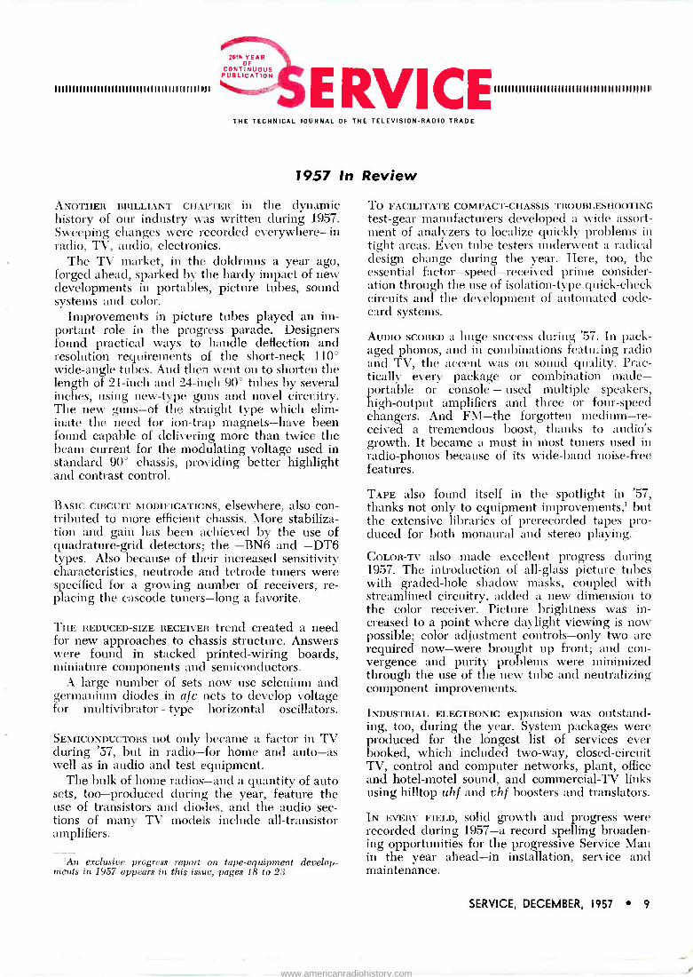
The effectiveness of varnish in re- FIG. 1: VERTICAL CHASSIS mounting moving heat is relatively small. Var- FIG. 2: ORIGINAL HORIZONTAL chassis
of recently -designed fin -cooled power nish being thin, it runs out on removal mounting, where fin assembly had to be
transformer which simplifies chassis lay- of the unit from the tank, leaving placed above the chassis. This mounting
out and removes heat problems. small air pockets througout the wind - has been modified as illustrated in Fig. 3.
14 SERVICE, DECEMBER, 1957
www.americanradiohistory.com

Transformers For TV Chassis
portion of the transformer by a con- siderable margin, and therefore this winding becomes the governing fac- tor in the thermodynamic design of the entire unit. Consequently, the transformer becomes larger, heavier, more expensive, and less reliable than would be the case if the means of dissipating the winding heat were more effective.
Filling Compounds
There are now available special filing compounds with improved thermal conductivity and good elec- trical insulating properties, which do not soften at operating temperatures. One of these is based on a liquid called Permafil', to which is added finely ground slate powder and a catalyst. At room temperature, the resulting mixture is very fluid. When the transformer is assembled, a seal- ing compound is inserted between the end shells and the lamination surfaces. The assembly is then baked at 290°F for one hour, which sets the sealer, thus leaving only the transformer lead hole as access to the inside of the transformer. The filled transformer is baked and cured at 275°F for five hours, at the end of which the entire assembly has become one solid rock- like unit.
The benefits obtained from the Permafil process are:
(1) The physical protection to the winding against shock and vibra- tion are at a maximum. There is no possibility of winding shift- ing. There is no deterioration of the insulating properties of the com- pound at temperatures consider- ably in excess of those that would represent a serious prob- lem with varnish. Since tempera- ture limits specified by Under- writers' Laboratories are still based on varnish impregnated construction, the insulating abil- ity of the compound should last indefinitely. A much heavier barrier against the penetration of humidity has been provided.
(4) There is now a continuous therm- ally conductive path throughout the entire assembly. This elim- inates the hot spots and greatly increases the rate at which heat
(2)
(3)
(5)
by J. C. SPINDLER
Engineering Department, Zenith Radio Corporation
can be removed from the critical innermost winding. The greatly improved cooling of the inner winding permits a redesign of the transformer to use less iron and copper. Reduc- tion in the copper wire size in- creases the copper losses, which however are now more rapidly dissipated. Since in transformer design the iron is kept at a con- stant flux density, the total iron loss is directly proportional to the weight of iron, and hence less pounds of iron result in less total watts of iron loss, thereby offsetting a part of the increased copper loss.
Having provided the means of getting heat more quickly from the inside to the outside of the trans- former, it now becomes necessary to transfer the heat more efficiently to the surrounding air. To do this both effectively and economically the fol- lowing factors must be considered: (l) The transformer iron is in closest
thermal contact with the inner surface of the innermost winding. While the transformer iron is a source of heat itself, it is also an excellent thermal conductor.
(2)
'Made by G. E.
O'`
FIG. 3: PRESENT MOUNTING on a hori- zontal chassis where short brackets are used and the fins protrude through holes in the chassis to take advantage of the cooler air available from openings in the
cabinet bottom.
(3) The transformer iron is in close thermal contact with about 70% of the outer and inner surfaces of the complete winding assem- bly.
(4) The transformer iron outer sur- face is flat and represents over 50% of the entire outer surface of the transformer.
In the structure finally evolved by engineering nested U-shaped pieces of .025" aluminum were clamped to the longer sides created by the lam- ination edges by means of two long studs. Nested U pieces have been found to be not only more economical, but provide additional strength to the final assembly.
This structure was found to provide the following advantages: (l) The innermost winding still
being the hottest, the means chosen are as directly effective on it as possible.
(2) Extension of the outer surface in this manner does not increase the internal volume of the trans- former body, and therefore the amount of Permafil required is not increased. Additional Perma- fil would not only be costly and increase weight, but by being in series with the thermal circuit would actually slow down the overall rate of heat transfer. Extension of the outer surface with this construction provides the maximum increased surface in contact with the air and the minimum of material and com- plexity of parts.
(4) The increased surfaces are verti- cal and therefore take full advantage of the natural con- vection (chimney effect) set up when air is heated. Maximum access is provided for entry of cool air at the bottom of the extended surface and easy exit is provided for the warm air at the top.
On a vertical chassis the trans- former is mounted by means of a
(Continued on page 41 )
(3)
(5)
SERVICE, DECEMBER, 1957 15
www.americanradiohistory.com

An entirely new type of
City and Suburban antenna
Powerful 2 -element T -W antenna outperforms a stacked conical.
Fully Super-Sembled - elements pop out in seconds.
o410001311310131 0 P.
It I lu I I i i r, r. I.
NEW a
upen Ghowman A More Powerful version of
the world's most beautiful indoor antenna
New Disappearing Dipoles for improved recepti: i on
Channels 2-6.
New Compressed Parasitic Reflector for improv=e reception on Channels 7-13.
Metro -Dyne Electronic Tuning reduces "ghost! ... rejects
unwanted signals... filters out electrical interferea:e on ALL
CHANNELS.
r
"INSTALL -IT -YOURSELF"
11[6 A Compl:te Antenra
ANTENNA KIT Insta lotion in pt - trac -h e 3 -Color Car- ton -- to help you crac< tie BIG- PRCF T "Do-It-YoLr- self" Ti -Let.
Available n stunning Mahagany and Geld or $189- Blond and Gold lis.t
:111
, ' .i
CHANNEL
You get valuable coupons redeemable fc -
di;tin:tive and useful gifts with every order for the rew Super Showman or T -W kit.
Pid< 'tom more than 135 FREE premiums .. .
featu rir g America's best known name brands.
fi,01"8>
Prornct tinnily Priced at
$29t
Ir c uding: 2 eglement T-' combination di minum mast cnd tripod mourt, vire, and F and ware.
www.americanradiohistory.com
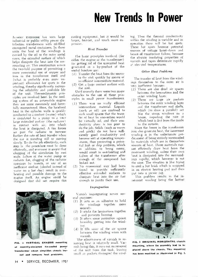
Troubleshooting Dual -Diode Horizontal AFC Circuits by JESSE DINES
Trouble
Loss of horizontal sync
IA)
Picture Indication Cause Remedy
The following components may have to be repla:ed: C0ä or C1:0 (.001 mfd), R146 or R1a; (100,000 ohmo )
(faulty) ; R141 (4.7 megohms) open; C141 (.01 mfd leaky; C196 (.006 mfd) shorted; R1;1 (33,000 ohms) or C,1,, (.001 mfd) open; R150 (4.7 megohms) faulty. -See circles 1, 2, 3, 4, 5 and 7 In Fig. 1.
The following components may also be defective: C10 or C143 (.001 mfd), R.,..6 or R42T (100,000 ohms), R42á (470,000 ohms), C146 ( .047 mfd), Cui (.01 mfd), R1:,.. ( 12,000 ohms), and R420 (4.7 megohms). -See circles 1, 2, 3, 4, 5 and 7 in Fig. 2.
Replace or re- pair defective component.
Vertical blanking bar; split picture.
IB)
C,,4 (.006 mfd) may be leaky, or R151 (33,000 ohms) increases in value. -See circles 4 and 5 in Fig. 2.
C147 (.01 mfd) and R430 (12,000 ohms) should also he checked for possible defects. -See circles 4 and 5 in Fig. 2.
Replace or re- pair defective component.
Piecrust or geartooth pattern.
ICI
The following components may be faulty: R,4, (4.7 megohms), C141 (.01 mfd), C,66 (.003 mfd) or R150
(4.7 megohms) . The .003-mfd capacitor may be open.-See circles 2, 3, 6 and 7 in Fig. 1.
Also check R,,. (.0047 mfd), C,1,: (.047 mfd), C,,5 (.0047 mfd) and R. (4.7 megohms) .
-See circles 2, 3, 6 and 7 in Fig. 2.
Replace or re- pair defective component.
Picture hook.
IDI
The following components may change in value: C138 (.006 mfd), C1:,9 (.003 mfd), C140 (.001 mfd), C145 (.01 mfd), R145 (22,000 ohms), R149 and R150
(4.7 megohms), and R,5, (33,000 ohms). -See circles 2, 3, 4, 5, 6, 7 and 8 in Fig. 1.
Also check C,15 (.0047 mfd), C416 (.047 mfd), C417
(.01 mfd), R,_0 and R,22 (470,000 ohms), and R,:0 (12.1100 ohms). -See circles 2, 3, 4, 5, 6 and 7 in Fig. 2.
Replace or re- pair defective component.
/
77PP
L v ua
/1.I SHORIZ
A F C6AL5
I 5 1
OHMS 10ö,0ó
`MFD, FROM tir
P
SYNC r` +614 7 CLIPPER
/C136 OHMS /100000, I
001 1
IMFO' RI46
AA
/ (CAT 77i( .a#,1\
6.5
6.57PP
I
IV1M FROM
COgI 33000 /THORIZ M `OHMS' TRANS RANST
006 MA
PP 49\ 4
R17
MES
TO 6567 HORIZ
OSC
(PLATE 1 C412 `.001 MEC/
FROM 6SN7 SYNC SEPARATOR
P
/^ 001
(CATHODE)
E157 P o / V / \ / \ 7v P P J `/ `
R426 ,100.000 - `OHMS
"100,000 5
V404
O1 .WY 1
li TO TAPON HORIZ OUTPUT TRANS
R430 / C41 .0047 0 5
OHMS MFG
56ALp5 ISC I II
1C0i H MFD / R4
470000 \ 1 OHMS
_i_ 7...\ 4.7 MER
420G , _, 7
TO 6557 HORIZ OSC -
/ ....
1z
eT.047 , C41` MFD
b FIGS. 1-2: The Fig. 1 diagram is the horizontal -Sync circuit used in the Crosley 393-394. Fig. 2 is the horizontal -sync circuit used in
the Admiral 22E2 chassis.
SERVICE, DECEMBER, 1957 17
www.americanradiohistory.com

A Field Progress Report on Latest Tape -Equipment Developments
FIG. 1: CONSOLE stereo tape payer.
THE RAPIDLY increasing use of tape equipment in the home is being re- flected by the steady rise in the pro- duction of prerecorded tapes, not only for monaural, but stereophonic reproduction. For stereo ('t' in -line), as well as standard (half or full -track) play, tape machines' of the type illus- trated in Fig. 1 have been developed.
Although the stereotape players were designed for use in conjunction with companion speaker units for stereophonic sound reproduction, the stereotape players can be used alone for monaural reproduction.
The tape transport mechanism in these models has four pushbuttons and a stop bar for controlling tape motion, and two pair of pushbuttons for selection of stereophonic or mon- aural playback amplification and for modification of recording character- istic. Knob -type controls are used to select operating speed, loudness, tone and type of external speaker system.
An in -line stereo record/playback head and a separate erase head are
Monaural Tape Recorder -
Dual -Purpose Unit Features 2 -Speed Operation
used. To thread, the tape is placed in a slot and secured to the takeup reel. A tape holdout lever holds the tape away from the heads during fast -forward and rewind; this prevents irritating squeaks and squawks when rewinding.
Other features of the tape transport mechanism are: Heavy balanced fly- wheel, flat linen take-up belt, shock - absorbent mounting and ac erase. The recording level can be set without the tape being in motion.
The tape -amplifier chassis` and a separate power -supply chassis' are both attached to the tape transport mechanism to make a single unit.
The amplifier has four dual ampli- fier tubes and two power output tubes: 12AX7 (two -stage preamp- left channel); 12AX7 (two -stage pre- amp-right channel); 12AX7 (two - channel a f ampl-playback or of ampl and neon ampl-record); 12AU7 (two -stage recording ampl); 6AQ5 (left -channel output-playback or 60- kc oscillator-record), and a 6AQ5 (right channel output-playback or neon amplifier-record).
The power unit has a 5Y3GT rec- tifier for B supply and a selenium rectifier for dc supply to the heaters of the preamp tubes.
Power output for each channel is 3 watts (undistorted) and 4.5 watts maximum.
Three speakers are used. In the console are one 8" and two 332' pm
units; the portable has one 6r and two 33z' pin speakers.
Circuit Description
The amplifier has been designed with two channels, each channel having four stages of playback ampli- fication. Switching is provided in the third stage to permit full power out- put with either stereophonic or con- ventional tapes.
The type of playback operation to be used can be selected by two push- buttons. When the buttons are in the stereo position, each channel is fed through separate preamps from the in -line stereo playback head. With the single pushbutton depressed, the in- put circuits of the 12AX7 left and right audio -amp channels (V3A and V38) are paralleled and fed from the output of the 12AX7 left channel preamp (V18).
A dual loudness and a dual tone control are used to provide equal playback amplification and tone in both channels. An adjustable gain control in the right - channel amp- lifier permits equalization of the gain of the two channels.
Monaural recordings can be made from a microphone or from another source or mixed if the input to the radio -phono jack is from a high -im- pedance source.
On record operation one stage (V,R) of microphone preamplification
FIGS. 3, 4 and 5: BLOCK DIAGRAMS of stereo playback and monaural record -playback systems used in RCA STR-6 8 tape machines.
Its
HEAD
LIME GAIN LINE LONT
DUAL VOL LOMT
1
`STEREO
STEREO-SINGLE/MARK 9WIiCN1 IN N
EAD
I "
II
! D)
LINE
e0tT0N
_ TOP
SINGLE PUSHBUTTON \
VOL COHT \
STEREO -JINGLE/MARK 9WI'CX
e'
w
-
-
V gA010->nOnL
INPIIT
IL
eM -
STERCO JI IKE/MA lWITCN
vJe,Ve VJ 9IPKp DA''
RIO NT CHAN
RIGHT / CNAN e'
RIGNT CÑAN AMPL
.7))
oft EAYP AYPL
J NRJ IExTI
NEON LAMPS
V]A, VJe e0TT0Y
TOI
v]e, va pl&rt CXAN lPKR! lE%TI
PUSNeUTTON
VJe,V!
v]A,VJ
NFON AMPL
H!'3 e0 KL OJC
II ERASE HEAD
-
C]! ts
LEFT
ANPL
qAYOPO
LEBT CMAM
MC1YP
IEFi LMAn CNAN
PREAMP CNAN
PR PL
RECORD HEAD Ii0P1 -
E' AYP
= AMPL ,
LEFT CHAN lPKRJ IINT,
vIe v]A
vOLUM[ COnT
-
VIA,VIB
VIA,vB vJA,V! LCRT CNAM lPNR! TINTI
VI,VIB
18 SERVICE, DECEMBER, 1957
www.americanradiohistory.com

by SAM F. P U S E Y , Service Engineer, RCA Service Co., Inc.
Stereotape Player
and 3 -Speaker System
is used ahead of the radio -phono in- put (top of volume control). Three subsequent stages (12AX7 and 12AU7; ; V ,, VIA and VIR) of audio amplification are used for recording. Inverse feedback is provided between the plate of VIR and the cathode of V.A.
A 6AQ5 (V3) serves two functions: On playback it is the left -channel output and on record it is a 60-kc oscillator. A switch (S, front) selects the input (audio or oscillator) to the grid of V5; the rear of this switch selects the load (output transformer or oscillator coil) connected to the plate of V,. In record operation the cathode of V, is connected directly to ground, and self -bias is provided by a 47,000 -ohm resistor in the grid osc coil circuit. The oscillator output is used for both erase and bias. The bias signal is mixed with the audio signal at the output of VIR and then applied to the upper record/ playback head through the rear of another switch (Si). The oscillator output is applied directly to the erase head.
Recording level is indicated by the flashing of two neon indicator lamps. The signal to the indicator lamps is supplied from the plate circuit of a 6AQ5; V.,. This signal is audio only and not a mixture of audio and bias.
Tape motion is controlled by three pushbuttons and a stop bar. A fourth pushbutton (monitor) of this group actuates the record -playback switch (S, and S8) only. When the monitor pushbutton is depressed, the record -
(Continued on page 40)
1RCA STR-6 and STR-8. 'RS -166. 'RS -167.
(Right, FIG. 6: COMPLETE CIRCUIT of RCA STR-6 8 stereo -monaural tape player -
recorder.
r
f-
9
_e -(F- is
11
äe
é5 --iF---
?I
iá
aro
I=
SERVICE, DECEMBER, 1957 19
www.americanradiohistory.com

A Field Progress Report on Latest Tape -Equipment Developments
AUDIO INSTALLATION AND SERVICE
Phono Tape PA
Cartridges Needles Amplifiers Speakers
Alignment and Test Procedures for Oscillator Coils in
Tape Recorders' . . . Troubleshooting Tape Equipment$
... Tools Required for Tape Repairs.
nnmm11uuuuumuuuuumuuunnmuumummummuunununnnmmmnm,n;nnununnununnnuuunum,umm11unuununuuumonnnmuunuumu unumi ilumu mimui mii iruua ii im u u uumuuu
IN ALIGNING oscillator coils in Cres- cent, Silvertone and Columbia tape recorders one must first determine if the oscillator is operating at its as- signed frequency of 52.5 kc. This can be determined by employing a coil' preset to 52.5 kc.
The coil can be placed in any con- venient sized can. The tap on the primary should be grounded to the coil can. A clip of some kind should be fastened to the outside of the can to permit connection to chassis of the unit under test. The other three leads should be unshielded and not over one -foot long.
Since the coil is set at the factory in open air, placing it in a can may affect its resonant point. As a result, it may be necessary to reset the coil by peaking against a known value
coil as in a new tape recorder in good operating condition.
The frequency check should be made by clipping the coil case to the chassis of the unit under test. Blue lead should go to the output of oscil- lator coil; this is the orange lead run- ning from oscillator coil to erase head. Red and black leads should go to any vtvm set on 50-v ac scale.
The powdered iron slug in the oscillator coil of the unit under test is then rotated to the point where maximum voltage reading is obtained on the vtvm. At this point a definite dipping of the meter should be noticed if the slug is turned in either direction.
A similar procedure can be fol- lowed for setting the 52.5-kc trap; all units do not contain a trap. Basically the same hookup is used, with the
TAPE COMPONENTS in Ampro equipment which require adjust- ments to cure pinch roller squeek: A-pinch roller, B-guide, C- set screw, D-adjust- ing cam screw, E-cap- stan, and F-takeup reel. G represents di- rection tape should be
pushed.
blue lead in this case connecting to the 12AX7 side of the trap. The trap is tuned by dipping meter to mini- mum rather than maximum voltage. (All readings should be taken in rec- ord position on a vtvm.)
After the frequency of the coil has been set, it should be determined if the erase and bias voltage are correct. On units using a 6V6 as oscillator, the erase voltage at 52.5 kc should be ap- proximately 70 v, with bias about 22 v. Readings are taken at the head socket in record position, with no signal input, using a vtvm.
On many units the erase voltage will run considerably higher. This is
a normal condition, since an increase in erase voltage is not detrimental, but a decrease (below 65 v) will cause incomplete erase and distortion. On units containing a 12AU7 as the oscillator, the erase voltage reading should be 100 v minimum, and bias voltage 50 v minimum.
Remedies for Other Tape Problems
IF THE ERASE voltage is proper, but bias voltage is not, value of capacitor feeding the erase voltage to the rec- ord head must be checked; also one should check for open or shorted rec- ord head.
For low erase voltage the 6V6 or 12AU7 oscillator should be checked; also values of feedback net- work consisting of resistor to ground and capacitor to grid of 6V6 or 12AU7. Erase head may be partially shorted; erase head should measure about 10 ohms.
One should also make a resistance check of the oscillator coil. The oscillator coil can be checked in the circuit if the head is removed from socket, and unit is in record position. Readings on units containing a 6V6 as
oscillator should be as follows: Across full primary, 14 ohms; lesser part of primary, approximately 3 ohms; and greater part, approximately 11 ohms. Secondary should measure approxi- mately 12 ohms. Readings on units containing a 12AU7 as oscillator should be approximately 16 ohms across full winding; 3.5 ohms across lesser part, and 12.5 ohms across greater part of winding. On units using a 6V6 as an oscillator, capacitor across primary of output transformer should be checked. And on units using a 12AU7 as an oscillator, capacitor
$ Based on service notes for Ampro tape recorders.
20 SERVICE, DECEMBER, 1957
www.americanradiohistory.com

coupling plate of 12AU7 to erase circuit should be checked.
If there is no erase voltage, one should check coil windings for con- tinuity; erase head for shorts; change- over switch to see if movement is suf- ficient to allow switch to go fully into record position; 6V6 or 12AU7; open capacitor, shorted resistor, or open leads in feedback network to grid of 6V6 or 12AU7. On units using a 6V6 as an oscillator, capacitor across primary of output transformer should be tested, and on units using a 12AU7 as an oscillator, capacitor coupling plate of 12AU7 to erase cir- cuit should be checked.
Pinch Roller Squeek Cured
PINCH ROLLER SQUEEK in a tape re- corder is a small constant noise, vari- ously described as monkey chatter, hiss, squeal or creaking.
To diagnose this trouble one can apply a pencil or other small smooth object, pressing back on tape between the pinch roller and guide if the noise disappears it is pinch roller squeek. The trouble is caused by too much tension on the tape between the pinch roller and capstan.
To correct this condition, the con- trol panel should be removed, tape put on machine, set screw loosened and play key depressed. With tape recorder running, adjusting cam screw should be turned (either way; it con- trols an eccentric) slowly until tension on tape between capstan and pinch roller is decreased sufficiently to elim- inate noise.
One should test for sufficient ten- sion by holding takeup reel from turn- ing. Tape should continue to move smoothly between capstan and pinch roller.
Tools required are a small Philips head screwdriver, a standard blade type screwdriver, a jeweler's screw- driver and a 5/16 spintite.
Removing Takeup Reel Scrapes
TAKEUP REEL SCRAPE is a small in- termittent scraping, not unlike the sound made by sandpaper on wood, sometimes higher pitched.
Two methods can be used to deter- mine the source of this trouble. In the first approach, with tape running, supply and takeup reels should be checked for evenness and freedom
(Continued on page 44)
'Crescent, Silvertone and Columbia tape recorders.
'Crescent Products part No. 700080.
SCHEMATIC of amplifier used in Crescent tape recorder models TR -773, 773A, 773B,
774, 774A and B.
SERVICE, DECEMBER, 1957 21
www.americanradiohistory.com

A Field Progress Report on Latest Tape -Equipment Developments
ERASE HEAD which removes recorded
sound from the tape automatically just
before the tape reaches the record head.
PHOTOMICROGRAPH showing lineup of iron -oxide particles in magnetic field. This is an actual section of magnetic recording tape with a signal on it made
visible by a special process.
TRACK NO 2 t =,KeaIF -.TRACK NO I
I /4" ^' -.RIGHT TRACK
129...e. -.LEFT TRACK
I.-II/4"--e1 W -.RIGHT TRACK suusr-=-1 LEFT TRACK
STEREOPHONIC SOUND showing the difference in head arrangement of (a)
dual track monaural recording, (b) stereo or binaural recording (in -line heads), (c)
stereo or binaural recording (staggered
heads).
Glossary of Monaural -Stereo
TAPE RECORDING has given new meaning to many words in the English language. Numerous terms long used in the field of sound have become important to the tape recorder user.
Here are definitions of some of the most common tape recording tenus.
A Wind: Magnetic tape wound on the reel with the dull, oxide -coated side of the tape toward the inside; the wind almost universally used today. Recorder design determines whether A or B wind tape is required.
Bias: A high -frequency alternating cur- rent fed into the recording circuit to eliminate distortion.
Binaural Recorder: A tape recorder which employs two separate recording channels or systems, each with its own microphone, amplifier, recording and playback heads and earphones. Record- ings using both systems are made simul- taneously on a single magnetic tape on two parallel tracks. Use of headphones for listening is necessary for true binaural effect.
Capstan: The spindle or shaft-often the motor shaft itself - which rotates against the tape, pulling it along at a constant speed on recording and play- back.
Microphones and Networks
Ceramic Microphone: Piezoelectric type microphone supplied with many tape recorders which employs a ceramic element to generate voltages. Extremely rugged, it requires more gain than does a crystal microphone.
Crossover Network: Filter circuits for a multiple loudspeaker system which sep- arates highs and lows and feeds each to the particular speaker designed to handle them.
°Based on data prepared by Minnesota
Mining and Manufacturing Co.
Crystal Microphone: Piezoelectric type microphone supplied with Inane tape re- corders which employs a natural crystal- usually Rochelle salt-as its element. As the diaphragm moves, it causes the crys- tal to generate electrical voltages. Should be handled with care, however, and never exposed to heat. Provides best quality of all inexpensive microphones.
Dual -Track Recorder: Usually a tape recorder with a recording head which covers half of the tape width, making it possible to record one track on the tape, then turn the reels over and record a second track in the opposite direction. Sometimes called a half-track recorder.
Dynamic Microphone: Electromagnetic type microphone which employs a mov- ing coil in a magnetic field to produce varying voltages.
Electromagnetic Type Microphone: Microphone using an electromagnet to produce varying voltages; includes ribbon or velocity microphones, dynamic or moving coil type, and reluctance, or mov- ing vane type.
Equalization: Either boosting or de- creasing the intensity of the low, middle or high tones of a recording during re- cording or playback or both. This com- pensation serves to correct any deficien- cies in the recording system and to increase the signal-to-noise ratio.
Gap: The tiny distance between the poles of the recording head, measured in mils. The head gap of most home re- corders may range from 1 mil down to 'i mil. The smaller the gap, the higher the frequency range of the tape recorder.
Heads-Alignment
Head Alignment: Positioning of the record -playback head on a tape recorder so that its gap is exactly perpendicular to the path of travel of the tape. Head misalignment would cause loss of high frequencies upon playback. Special head alignment testing tapes are available.
"Such as Scotch timing tape 43P.
22 SERVICE, DECEMBER, 1957
www.americanradiohistory.com
.11 111H'. JIIP 1111111111111
Tape Recording -Playback Terms
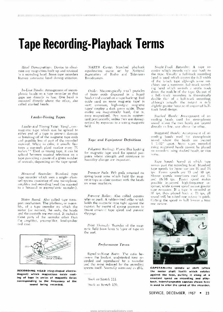
Head Demagnetizer: Device to elimi- nate any magnetism built up and retained in a recording head. Some tape recorders feature automatic head demagnetization.
In -Line Heads: Arrangement of stereo- phonic heads on a tape recorder so that gaps are directly in line. One head is mounted directly above the other; also called stacked heads.
Leader -Timing Tapes
Leader and Timing Tape: Tough, non- magnetic tape which can be spliced to either end of a tape to prevent damage or breaking off of the magnetic tape ends and possible loss of part of the recorded material. White in color, it usually fea- tures a one -inch plaid marker every 711
inches.** Used as timing tape, it can be spliced between musical selections on a tape providing a pause of a given number of seconds, depending on the tape speed.
Monaural Recorder: Standard type tape recorder which uses a single- chan- nel system consisting of one microphone, amplifier and recording head (as opposed to a binaural or stereophonic recorder).
Motor Board: Also called tape trans- port mechanism. The platform, or assem- bly, of a tape recorder on which the motor (or motors), the reels, the heads and the controls are mounted. It includes those parts of the recorder other than the amplifier, preamplifier, loudspeaker and case.
COIL
OXIDE BACKING
N'AVELENCTH
RECORDINC
HEAD
POLES REVERSE AS
CURRENT ALTERNATES
RECORDING HEAD (ring -shaped electro- magnet) which magnetizes oxide coat- ing of tape in series of magnetic fields corresponding to the frequency of the
sound being recorded.
NARTB Curve: Standard playback equalization curve set by National Association of Radio and Television Broadcasters.
Oxide: microscopically small particles of ferric oxide dispersed in a liquid binder and coated on a tape backing. Red oxide used on some magnetic tape' is most common; high -output magnetic tapes' employ a dark green oxide. These oxides are magnetically hard; that is, once magnetized, they remain magnet- ized permanently, unless they are demag- netized by exposure to a strong magnetic field.
Tape and Equipment Definitions
Polyester Backing: Plastic film backing for magnetic tape used for special pur- poses where strength and resistance to humidity change are important.
Pressure Pads: Felt pads mounted on spring -brass anos which hold the mag- netic tape in close contact with the heads on some machines.
Pressure Roller: Also called capstan idler or puck. A rubber -tired roller which holds the magnetic tape tight against the capstan by means of spring pressure to insure constant tape speed and prevent slippage.
Print Through: Transfer of the mag- netic field from layer to layer of tape on the reel.
Performance Terms
Signal -to -Noise Ratio: The ratio be- tween the loudest, undistorted tone re- corded and reproduced by a recorder and the noise induced by the recording system itself. Normally measured in db's.
'Such as Scotch 111.
-Such as Scotch 120.
Single -Track Recorder: A tape re- corder which records only one track on the tape. Usually a full -track recording head is used which covers the full width of the 11 -inch tape al lough some ma- chines use a narrower, half-track record- ing head which records a single track down the middle of the tape. Output of a full - track recording is theoretically double that of a half-track recording, although actually the output is only slightly greater because of improved half- track head design.
Stacked Heads: Arrangement of re- cording heads used for stereophonic sound where the two heads are located directly in line, one above the other.
Staggered Heads: Arrangement of re- cording heads used for stereophonic sound where the heads are located 1 7/32" apart. Stern tapes recorded using staggered heads cannot be played on recorders using stacked heads, or vice versa.
Tape Speed: Speed at which tape moves past the recording head. Standard tape speeds for home use are 3% and 7',2
ips. Faster speeds are 15 and :30 ips. Slower speeds sometimes used are Ii. and 15/16 ips. Faster speed makes possible improved high -frequency re- sponse, while slower speed means greater tape economy. If a tape is recorded at 3% ips, then played back at 731 ips, all sound will he raised one octave in pitch. Cutting the speed in half lowers a tone one octave.
CAPSTAN-the spindle or shaft (often the motor shaft itself) which rotates against the tape, pulling it along at a constant speed on recording and play- back. Interchangeable capstan shown here is used to alter the speed of the recorder.
SERVICE, DECEMBER, 1957 23
www.americanradiohistory.com

£MC3 MCfr FIELD AND SHOP
c Qoo 000 uuo
0.099
Troubleshooting AM -FM Tuners # . . . TV Tuner Detent Spring
Lubrication ... Fuse -Resistor Replacements ... Ringing Cures
111m11n11m1111!!!11!!!!!!!!!!!!!1111!!1111!111111!!!1111m n!1111111111!!!!!!!!!
WITH THE ADVENT of high-fidelity, the AM -FM tuner has found a perma- nent place for itself, in view of the performance features of FM - ex- tended audio range and greater inter- ference rejection characteristics re- quired for high-fidelity sound.
In FM operation, tuners (Fig. 1) use the following stages; an rf ampli- fier, mixer, local oscillator, two if amplifiers, a ratio detector, tuning -eye indicator and audio amplifier.
A 300 ohm, built-in antenna is coupled to the grid of the pentode rf amplifier through an impedance - matching network. This network matches the antenna impedance to the input impedance of the tube, at the FM frequencies, to permit maximum transfer of energy. Capacitor C, and resistor R, provide the necessary grid bias. The resistor -capacitor networks in the screen and plate circuits of the 6BJ6 rf amplifier are for decoupling; to prevent unwanted regenerative coupling between the rf and if -ampli- fier stages of the tuner.
One half of a 12AT7 dual -triode tube is employed as a local oscillator and the other half as a mixer. Perme- ability tuning is used to vary the oscillator frequency and tune the rf coupling transformer between the rf amplifier and mixer stages; C. and R, develop the grid -leak bias for the oscillator tube. Capacitor C. is a nega- tive -coefficient type and compensates for oscillator drift during warmup time.
The oscillator signal, taken from the grid of the oscillator tube, is fed
to the grid of the mixer through a capacitor, C8. The rf signal is coupled from the secondary of the coupling transformer to the mixer grid through capacitor C9. The gain of the mixer stage is controlled by the avc control voltage applied to the grid of the mixer tube through R,.
Mixer IF Output Coupling
The mixer if output is coupled to the first if amplifier by transformer T,. Two stages of if amplification are used to provide increased receiver selectivity and sensitivity. The second if amplifier stage is not operated as a limiter because the ratio detector does its own limiting. C. prevents the avc control voltage from being shorted to ground and couples the if signal from the transformer to the if ampli- fier grid. R. and R. drop the avc vol- tage to the if amplifier grids. Cathode bias for the first and second if stages is provided by a pair of resistors, R9 and R,;. Possible if regeneration is prevented by not bypassing these re- sistors, thus creating degeneration for both stages.
An unbalanced ratio detector is used to develop the audio signal. Limiting is accomplished by the sta- bilizing voltage developed across R19-
C,ei this voltage compensates for changes in the carrier amplitude. This voltage is also used to drive a tuning indicator, and serves as the avc con -
$Based on a report prepared by Sol Libes, editor of the Westinghouse Tech - Lit News.
trol voltage for the mixer, first and second if amplifier stages. R,, -C,, form a load for the detector diodes. The audio voltage appearing across capaci- tor C,, is coupled to the audio ampli- fier through a deemphasis network.
An if amplifier is common to both AM and FM operation. Separate if transformers, one for AM and the other for FM, are connected in series. Because the AM coils operate at 455 kc and the FM coils at 10.7 mc, the AM coils have many more turns and a higher inductance than the FM coils. As a result, when operating on AM, the AM signal at 455 kc has little impedance from the small FM coil; the signal acts as though the FM coil is shorted out. When operat- ing on FM, the capacitor across the AM coils offers virtually no impedance to the FM signal at 10.7 mc, and thus shorts out the AM coils. The if trans- formers, therefore, do not affect each other and may be connected together.
Troubleshooting the Tuner
If the AM section is found to be in good operation, FM can be checked by first feeding an AM modulated signal at 10.7 mc to the last if amplifier grid. The generator should be adjusted for full output and the frequency control wobbled to each side of 10.7 mc. If the if amplifier and ratio detector are operating properly, a modulation note will be heard. As the frequency con- trol is rotated away from 10.7 mc the note will be fairly loud. As 10.7 mc is
approached and reached, the note will dip sharply in loudness. As the fre- quency control is moved off frequency to the other side, the note will rise to its previous loudness. This procedure should be performed slowly to hear the sharp dip in loudness.
This procedure should be repeated, loosely coupling the signal to the grid of the first if amplifier. Absence of the note indicates that this stage is not functioning. If this stage is operating properly, you should move to the mixer grid and repeat this procedure.
To check the FM oscillator, a mod- ulated signal should be fed, at an rf frequency, to the mixer grid to ob- serve mixing action. If your generator does not reach these frequencies but does reach, say, 15 mc, the harmonics of the generator signal can be used. For example, the 11th, 12th and 13th harmonics of 8 mc are 88, 96 and 104 mc, respectively, and can be used to check oscillator operation, since these frequencies are within the FM band. The rf generator should be tuned to 8 mc and the output con- nected to the mixer grid. The tuning dial should then be turned to 88, 96
24 SERVICE, DECEMBER, 1957
www.americanradiohistory.com

and 104 mc. If the oscillator is work- ing, the modulation note will be heard at each of these positions, when the generator is wobbled. If the note is not heard, a defective oscillator may be the cause.
A negative do voltage measured with a vtvm at the oscillator grid is another indication that the oscillator is not operating.
The rf amplifier can be checked in the same manner as the oscillator, ex- cept that the 8 -mc signal must be fed to the grid of the if amplifier. This same procedure can be used to check the antenna.
Solving Ringing Problems
INDICATIONS of ringing are either a ripple or wave in the scanning lines on the left side of the picture or white vertical lines in the same location, or both. The location of this trouble is usually in the horizontal winding of the deflection yoke.
The high pulse of voltage appear- ing in the horizontal -output circuit during horizontal retrace, tends to produce a shock -excited oscillation in the circuit. As a result of the high harmonic content of the pulse, a few cycles of damped oscillation can be produced at a harmonic frequency, if the circuit components resonate at that frequency. This effect some- times occurs when the horizontal winding of the deflection yoke or, in some instances, the linearity coil, resonates with the distributed ca- pacity at the fourth harmonic (rough- ly 70 kc) of the pulse frequency. When this ringing occurs, the linear- ity at the left of the raster is effected.
Ringing Replacement Parts
To minimize ringing effects, a 51 or 43-mmfd capacitor should be con- nected in parallel with one-half of the horizontal winding of the deflec- tion yoke. The capacitor serves to make the reactances of the two sec- tions of the horizontal winding equal and opposite at the ringing frequency, so that the ringing effect is cancelled. If ringing occurs, it may be due to an open capacitor which was the cause of this trouble, or the capacitor may be of the wrong value for the particular yoke. If so, different values of capacitance should be tried. Sug- gested trial values are 33, 43, 47, 51, 56 or 68 mmfd.
In some cases it may be necessary to replace the deflection yoke to cure ringing symptoms. This represents a last resort, however, and the measures
68A6 'ST IF TWO C15
IST IF AYA
TI -R- IT
u
h MATT OSCILLATOR
210 IF rills
ri
10
1
68A6 6AL5 01O If AUF RATIO KT 01$C611MT01
TUNS
AIC I AIs CII di 11Y
II IAIe ;iM/=NN'
4E23 ;CA AIA _All. A1A NAYC J
6AU6
CAI A11710 Ate
020
FIG. 1: CIRCUIT of FM section of AM -FM tuner used in Westinghouse chassis.
previously mentioned should be tried first
Tuner Detent Spring Lubrication
THE DETENT SPRING life in Magnavox 700584 and 700587 tuners can be ex- tended by applying lubriplate 105 at the point of contact between the detent gear and spring. This lubri- cant should be applied generously.
Fuse -Resistor and Ballast Replacements
ALTHOUGH THERE are hundreds of thousands of fuse -resistors and line - voltage ballasts in radio -TV sets, some misunderstanding as to their purpose still exists.
Occasionally fuse - resistors, are claimed to fail as replacements. In checking returned units, it has been found that they have functioned as originally intended; that is, burned out when overloaded. The difficulty has been found to lie in the indi- vidual application.
The fuse -resistor serves a dual pur- pose in its application:
(1)
(2)
Manufacturers of certain types of rectifiers specify that a dropping resistor of from 5 to 15 ohms be used in series with their rectifiers to absorb peak surges that may be present in the line -voltage.
Underwriters recommend that these circuits be fused to eliminate the possibility of fire occuring in the set when surges occur at a higher level than the resistor will reduce to safe value.
The fuse - resistor is designed to function for both of these conditions. Causes for failure or blowing may be
$Based on a report by Fran J. Chamberlain, Clarostat Manufacturing Co., Inc.
attributed to two commonly -known factors:
(1)
(2)
The line -voltage source, hav- ing fluctuations reaching a high peak value and remain- ing there long enough to cause the fuse -resistor to burn out. Or... Through aging of parts in the set, causing an increase in the load. Such increase will in- crease the current through the fuse -resistor. If this current reaches or exceeds the rating of the fuse -resistor for over the time limit rating, it will burn out.
A simple remedy for the first con- dition is the use of external dropping resistors or a regulator. Line -voltage regulators will perform this function satisfactorily and are available in sev- eral sizes for various load wattages. For the second condition, they will function as a temporary remedy; but eventually, parts causing added load will need to be replaced while the regulator can still be used against fu- ture conditions of this nature.
It must be remembered that the fuse -resistor is an expendable item designed to burn out in protecting expensive components of a set. Amp- erage in excess of normal operating current is responsible for fuse burn- outs. Fuse after fuse could be in- stalled and each one would perform as expected, namely, burn out. Using a higher rating fuse -resistor would be
(Continued on page 41)
FIG. 2: POINT of lubrication in tuner detent spring. Both sides of the point of contact on the detent spring, as well as the point of contact, should be well
lubricated.
SERVICE, DECEMBER, 1957 25
www.americanradiohistory.com
FOR A
bri ht
TV picture
Rely on the tube that has always been speci- fied by leading independent set makers.
,, lfJJia /' i // (
TU NG -SOL: Magic Mirror Aluminized
PICTURE TUBES TUNG-SOL ELECTRIC INC., Newark 4, N. J. Sales Offices: Atlanta, Ga.; Columbus, Ohio; Culver City, Calif.; Dallas, Tex.; Denver, Colo.; Detroit, Mich.; Irvington, N. J.; Melrose Park, Ill.; Newark, N. 1.; Seattle, Wash.
CATALOGS -BOOKS
JFD ELECTRONICS, INC., 6101 16th Ave., Brooklyn 4, N. Y.,
has published two brochures to stimulate indoor antenna and TV accessory business. The indoor -antenna brochure ( 6 pages ), which describes and illustrates JFD indoor anten- nas now in use, from the deluxe Magic Genie to the Venus table -top rabbit ear model, can be used as a streamer or reference to the line covering applications and specifica- tions of the various models. . . . The second circular de- scribes outdoor and indoor set couplers, outdoor -indoor an- tenna couplers, wave traps, baluns, impedance matching transformers, antenna isolators, attenuators and switches. [SERVICE]
o e e
THE HowAnn W. SAMS & Co., Inc., 2201 E. 46th St., Indianapolis 5, Ind., has issued volume 7 of the Tube Location Guide series, which show chassis layout of TV receivers, types of tubes used, and function of each tube. Also included is a tuhe failure check chart which lists the tubes which are to he suspected when the indicated trouble is experienced. ... Volume 7 covers 160 chassis (approximately 500 models) of TV receivers produced in '56 and '57, including three color -TV chassis. . . . Contains 204 pages; priced at 82.00. [SEnvicE]
e e ex
THE RADIO - ELECTRONIC MASTER, 60 I\ladison Avenue, Ilempstead, N. Y., has compiled a chart on panel and flashlight lamps. Chart is a composite listing, arranged numerically, of panel and flashlight lamps manufactured by Chicago Miniature, G. E., National Carbon ( Eveready ), RCA, Raytheon, Tung -Sol and Westinghouse. [SERvIcE]
e n o
CLEVELAND INSTITUTE OF RADIO ELECTRONICS, 4900 Euclid Ave., Cleveland 3, 0., has issued a 24 -page booklet, Oppor- tunities in Electronics for You, designed to provide pictorial coverage of opportunities in electronics, plus thumbnail de- scriptions of many of the available employment opportunities. [SERVICE]
e n o
UNIVERSITY LOUDSPEAKER, INC., 80 S. Kensico Avenue, White Plains, N. Y., has published a 12 -page illustrated cata- log covering high fidelity speakers, systems and enclosures, and do-it-yourself enclosure kits. Also detailed are paging and talk -back speakers, heavy duty trumpets and driver units, submergence -proof speakers, portable soundcastiog systems, and super -power projectors. [SERVICE]
n n er
THE 1958 POCKET-SIZE EDITION of the RCA Reference Book is now available. through RCA distributors. Contains 216 pages of information on RCA tubes, test equipment, batteries, transistors, and semiconductor diodes. Includes a Quick Selection Guide of RCA power tubes, crt, phototubes, special tubes, and semiconductor devices, as well as 50 pages of re- ceiving tube characteristics, with base and envelope dia- grams. Picture tube characteristics and socket diagrams occupy 13 pages. Also has lid erebangeabiliti Directories for tubes, transistors, and batteries, a daily reminder calendar, and 16 pages of world maps in color. [SERVICE]
e * c
THE HICKOK ELECTRICAL INSTRUMENT CO., 10521 Dupont Ave., Cleveland 8, 0., has prepared an 8 -page composite test equipment catalog, form SM -31. Compilation lists 24 instruments including color generators and the Cardmatic automatic tube tester. [SERVICE]
n n e
BUSSMANN MANUFACTURING Co., University at Jefferson, St. Louis 7, Mo., has issued a 52 -page TV fuse chart booklet which shows proper fuses to use for TV, as well as auto- radios and Christmas -tree light sets. Detailed also are fuse mounts and information on circuits fuse protects. [SERVICE]
e n n
MERIT COIL AND TRANSFORMER CORP., 4427 N. Clark St., Chicago 40, Ill., has released a wall -chart -type exact replacement guide for transformers, flybacks, yokes and coils. [SERVICE]
26 SERVICE, DECEMBER, 1957
www.americanradiohistory.com
ASSOCIATIONS TEA, Fort Worth, Texas
THE FIRST isSUE of the TEA Tinges has been published by the Texas Electronics Association, Inc.
Contents include an editorial by TEA president W. J. Inman, Sr., stressing the need for strong business and tech- nical educational programs and unified participation among Service Men and associations; also local association news, technical service tips, and minutes of recent meetings. The journal also contains an announcement that the fifth annual clinic will be held in Dallas, Texas, at the Baker Hotel on August 1, 2 and 3, 1958. Chairman of the convention is Tillman Babb.
u c c
RTTA, California HENRY C. LEVECK has been elected president of the Radio - Television Technicians Association of Orange County, Calif.
Others named include George Morgan, vice president; Gordon Maurer, treasurer, and Francis Rice, secretary.
c c c
IRTSA, Wis.
AT A RECENT MEETING of the Indianhead Radio - TV Servicemen's Association, Wis., Len Rubbers, an instructor at Northwest Radio and Television Schools, Minneapolis, Minn., appeared as a guest speaker and covered the proper method of obtaining an overall response curve and proper TV align- ment procedures, explaining an alignment process on a mis - adjusted set and showing the differences in alignment for fringe areas and local reception.
NATESA
THE CUP RENT ISSUE of the NATESA 'Scope features a letter from FCC chairman John C. Doerfer, thanking members of the association for their cooperation in filling out and return- ing the industry questionnaires on TV reception conditions submitted by the Television Allocations Study Organization in Washington.
TEN YEARS AGO IN SERVICE
THE ROCHESTER r ii',PTEII of the Radio Technicians Guild held a two-day technical -business session. Plans were made to form ten state guilds which would become members of a
Radio Technicians Guild of New York State. Bertram L. Lewis was named chairman of a ten -man guild committee. AVilliam Brewerton was named to assist Lewis. David Boyce, presi- dent of RTG, said the federation would help exchange in- formation on trade techniques, provide for standardization of servicing procedures and establish codes which would pro- mote good will and better business. Among those at the meet- ing were Ben DeYoung, president of the Ithaca chapter, Technicians Guild; E. M. Howland, who represented the Hudson Valley Radio Servicemen's Association; Leo N. Burt of the Jamestown Radio Men's Association, and Ted Telaak, president of The Buffalo Servicemen's Association. . . One of the guest speakers at the meeting, Dave Krantz, described the operation of the Federation of Radio Servicemen's Associations of Pennsylvania, of which he was chairman. Other speakers at the sessions were A. C. W. Saunders and B. V. French. . The Whaling City Chapter of the Radio Technicians Guild in New Bedford, Mass., was reorganized and Al \Vobecky elected president. John Santos, Harry Wood and Albert Gagnon were appointed as a committee to study revision of the bylaws. . . . The first annual convention of the Federation of Radio Servicemen's Associations of Pentisvl aria was announced for January 11-13, 1948, at the Bellevue -Stratford hotel in Philadelphia. The Philadelphia Radio Service Men's Association was named convention host. ... Scheduled as a feature of the convention was the Town Meeting of Radio Technicians, a joint undertaking of RMA, the Sales Managers' Club, NEDA, EPEM and the Mid -Atlantic Chapter of The Representatives, with the assistance and cooperation of FRSAP and PRSMA.
FOR A
righter
fit btu re
Rely on the tube that has always been a
favorite with leading independent. service dealers.
waibt
Hc-soI: RECEIVINruG TUBES
TUNG-SOL makes All -Glass Sealed Beam Lamps, Miniature Lamps,
Signal Flashers, Picture Tubes, Radio, TV and Special Purpose
Electron Tubes and Semiconductor Products.
SERVICE, DECEMBER, 1957 27
www.americanradiohistory.com

ANNUAL INDEX January -December, 1957
ANTENNAS (TV-Two-Way)
A Report on 1 \ -Antenna Replacement Market Study Dec.
All -Band VHF -Antenna Fringe -Area In- stallations; Jack Darr Feb.
Analysis of an Indoor TV Antenna Using Single Vertical -Element Rod far Pickup; Matthew Mandl May
Color -TV Transmission -Line Checks With TV Alignment Equipment; Robert Kerzman Apr.
Community -TV Long Transmission Lines; Jack Darr June
Design -Application Analysis of a Diplexer 2 -Set Coupler; Harold Harris Aug.
Design -Application Report on a Variable Control PW-Tuning-Element Indoor Di- pole Mar.
How to Develop an Antenna -Replacement Program Nov.
Latest Two -Way Developments: Short An- tennas; Leo Sands June
Line -Loss Equalization in Low -High -Band TV Systems Apr.
Repeaters, Antennas, Test Equipment for Two -Way Oct.
Rooftop TV - Antenna - Mast Multiple -Set - Coupler Installations Jan.
TV -Antenna Replacement Field -Investiga- tion Report July
TV -Antenna Replacement With All -Chan- nel Types Oct.
TV -Antenna Tower Installation Sept.
AUDIO (Commercial Sound-Radio-Phono-
Tape) A Guide to the Selection of Phono Replace-
ment Cartridges; G. A. Morrell, Jr Nov. A Packaged 4 -Speaker Hi-Fi Radio -Phono;
Roy S. Fine Nov. A Report on the Useful Life of Hi-Fi Com-
ponents and Accessories Jan. Alignment and Test Procedures for Oscil-
lator Coils in Tape Recorders . .
Troubleshooting Tape Equipment .
Tools Required for Tape Repairs Dec. AM -FM -Phono With Push -Button Loudness
Control in Preamp; Harry Schmidt Aug. AM -FM Radio -Phono With Mood -Music
Control; C. C. Kayhart May Amplifiers for Outdoor Commercial Sound
Systems; Norman Crowhurst June Changing Needles in Phonos .. Mechani-
cal -Feedback Vibration -Distortion Cures Crystal -Ceramic Pickup Replace-
ment With Magnetic Types July Commercial Sound Cables; Frank Timmons Feb. Cures for Hum in Amplifiers and Preampli-
fiers Sept. Diamonds Are a Record's Best Friend;
Robert G. Walcott Nov. Dropout and Modulation -Noise Problems in
Tape Oct. Eliminating Distortion in Transitor-Radio
Audio Sept. Features of New Types of Tone Arms and
Pickups Nov. Field -Bench Facilities of Shop Specializ-
ing in Commercial Sound; Kenneth Sonnenberg May
Glossary of Tape Recording - Playback Terms Dec.
Monaural Tape Recorder -Stereotape Player; Sam F. Pusey Dec.
Motel Sound -System Installation; L. A Randall Oct.
9 -Transistor 20 -Watt AF Amplifier; George Young Dec.
Outdoor Amplifiers for Commercial Sound; Norman Crowhurst July
Outdoor Transformer Replacements LF Instability Cures . . . Square -Wave Testing June
Output -Transformer Replacement May Phono Pickup Tests Before Installation to
Insure Best Results Aug. Portable -Phono Transistor -Amp Servicing;
Norman Crowhurst Apr. Regulated Power Supplies Sept. Remedies for Phono Motor Noise, Grille
Static Charges Sept. Replacement of Pickups, Styli and Phono
Motors in Portable Phonos Apr. Round and \Vide -Angle Horns; Lawrence
J. Epstein May Servicing Carrier -Current Wireless Inter-
coms Dec. Servicing Commercial and Home Hi-Fi
Systems; Ernest A. Dahl Nov. Servicing Transistor Portables and Audio
Circuits Mar. Small Store -Office Announce -Music Sound
System Installation -Repair; Jack Darr Mar. Sound Is King; Maurice E. Swift Nov. Transistor -Amp Portable -Phono Circuitry
Tape -Recording Repair Tips . .
4 -Speed Player Servicing Feb. Troubleshooting AM -FM Tuners Dec.
CIRCUIT DIAGRAMS AC Wattmeter May Admiral Color -TV Chrominance Channel May Admiral 8F1 Remote -Control Amplifier
(Complete Circuit) Nov. Admiral 14UY3B Portable -TV Horiz-Sync Apr. Admiral 22E2 Horiz-Sync Dec. Admiral 42SB Audio Amp With Remote
Control Nov. Admiral 94E119-1 Portable -TV Tuner
(Complete Circuit) Apr. Admiral Pentode Disc -Type VHF Tuner
RF-Mixer (Cover) Apr. Admiral Remote Circuitry for Power,
Phono, Radio, Amplifier and TV Nov. Admiral Resonator Remote -Control Func-
tional Schematic Nov. Admiral 20T1 -20V1 Isolation Transformer
Circuit May Admiral 23A1 Horiz Sync Nov. Aerovox AF -Module Preamp Apr. Aerovox Module Preamp-Mixer Apr. AF Circuits Modified to Prevent LF In-
stability and Blocking June Alignment Test Setups July AM -FM Phono Power Amp-Preamp With
Push -Button Loudness Control (Cover).Aug. Amp Automatic Bias June Amp Separate Resistor Biasing June Amp Test Setup May Antenna Matching Networks Oct. Auto -Radio Electro -Tuning Apr. Auto -Radio PNP Transistor Diagrams Apr. Auto -Radio Transistor Circuits Apr. Autotransformer HV TV System May B&K Flying Spot Scanner Video Generator Mar. Basic Colpitts, Ultraudion and Push -Pull
Oscillators July Basic Microwave System Mar. Battery -Set Power Supply May Bennett 100 Wireless Intercom Dec. Bifilar Elevator Coupler Aug. Blocking TV Oscillators Jan. Cartridge Checker With Low -Level Input
Standard Aug. Cathode -Bypass Capacitor Test Circuit Mar. Color -TV Dynamic Covergence Circuit for
Glass Picture Tube (Cover) Oct. Color -TV Shading Control Mar. Color -TV Switching Circuits for Gun Bias-
ing Oct. Commercial -Sound Amp Power Supply June Commercial - Sound Mike - Speaker Amp
Rack June Computer Control Trans Multivibrator
(Cover) to Sept. Computer Control Tube Dual -Cathode Fol-
lower (Cover) Sept. Coupling -Capacitor Insulation Test Mar. Crescent Tape Amp for TR -773 A/B and
774 A/B Dec. CRL 4 -Stage Trans Amp Sept. Crosley 393-394 Horiz-Sync Dec. Crosley 431 Autotransformer Circuit May Crosley 9-408 Synchralock Sept. Crosley 10-428MX Synchroguide June Delco Transistor (1N278 PNP) Radio Out-
put Feb. Direct -Drive IlV TV System May Du Mont RA -372-3 Component Changes to
Eliminate Vertical Jitter Aug. Du Mont RA -380/381 Component Changes Sept. Electric Coffee Percolator Test Board May Emerson Chassis Change to Improve AGC June Emerson 867B RF -AF Modules May Emerson 1258-59-68-69 Revised to Elim-
inate Ringing June Engineered Electronics Crystal Ose
(Cover) Sept. Engineered Electronics Phase -Shift Osc Sept. Engineered Electronics P -P Volt Amp Sept. Engineered Electronics Squaring Amp, - Sept. Engineered Electronics Tube Dual -Cathode
Follower Sept. Engineered Electronics Tube Multivibrator Sept. Expanded Microwave Network Mar. 5U4 -6X4 Test Circuit June Four - Channel Ultrasonic Remote - Control
Amplifier (Cover) Nov. Gaseous Voltage -Regulator Test Circuit June G.E. 17TO25 Portable -TV Sync Separator Apr. G.E. 805-6-7-9 Gruen Horiz AFC Aug. Germanium Rectifier Circuitry Apr. G -M 13 -Transistor Auto Radio (Complete
May Aug. Jan.
Circuit) Grounded -Grid RF Stage Heater -Circuit Change to Limit Hum HF -Rolloff Improvement May Hoffman Solaradio 411 (Complete Circuit) June IF Loading Circuitry Nov. In -Circuit Horizontal -System Short Test
Circuit Jan. Indoor -Antenna PW-Assembly Equivalent
Circuit Mar. Infinite -Gain Stage Amp June Instantaneous Screen -Voltage Regulator June Intermittent Electrolytic Test Setup Feb. Internal -Outdoor Speaker Output Circuit Mar. IQ Color -TV Receiving System May Isolation -Transformer HV TV System May
Knee -GM 'lest June Magnavox CT/C'U/CM4401B Sweep Feb. Magnavox HV -Transformer Circuit Modi-
fied for AGC-Keying Pulse Oct. Magnavox 25 -Watt Power Amp May Magnavox 295C AM -FM -Phono (Complete
Circuit) May Magnavox Mood -Music Control for AM -FM
Radio -Phono (Cover) Marker Adder -'Scope for Alignment Miniaturized Circuitry (Cover)
May Mar. Sept.
Mobile 2 -Way as Paging System June Motorola AM -FM -Phono Radio (Complete
Circuit) Aug. Motorola Auto -Radio AF Output Apr. Motorola Auto -Radio RF With Limiter Apr. Motorola Auto -Radio Transistor AF Apr. Motorola Auto -Radio 12-V Supply Apr. Motorola Auto -Radio Vibrator Power Sup-
ply Apr. Motorola 918-919 Circuit Revised to Mini-
mize Motor Noise Oct. Motorola Preamp With Loudness Control Aug. Motorola TS -9 Pulse -Width June Motorola TS - 422A - 00 Cascode - Pentode
Tuners Feb. Motorola TS -422A-00 (Complete Circuit) Feb. Motorola TS -422A-00 PW Chassis Power
Supply Feb. Motorola TS -422A-00 TV Horiz/Osc/HV
Rectifier Section of PW Packaged -Assem- bly Chassis (Cover) Feb.
Motorola 25 -Watt Power Amp Aug. Multiple Cartridge Checker Aug. Olympic CT Portable -TV LV Supply Apr. 1B3 -1X2 Test Circuit June 110° 21 -Inch Horizontal -Vertical Deflection
Circuitry (Cover) July Output Transformer Tapping July Padding to Eliminate Amp Hum Sept. Pentodes as Triodes in AF Output May Pentode -Tuner RF Amp Oct. Philco 8H25 Contrast Control Sept. Philco Transistor Auto -Radio With Feed-
back Apr. Picture Blanking During Retrace Sept. Picture -Tube Flux Cancellation July PNP Transistor Audio Stage Apr. Portable -TV Doubler Circuitry Apr. Power Supply Filter -Test Circuit Mar. Preamp for High and Low -Level Pickup
Checking Aug. Printed - Wiring Indoor - Antenna Tuning
Element Mar. Radio -Phono Amplifier Mar. RCA 8/9BT-9 Conv-IF-Det Transistor
Stages July RCA CTC7 (800 Series) Color -TV Block
Diagram Oct. RCA 800 Series Color -TV Chassis (Com-
plete Circuit) Oct. RCA 800 Series Color - TV VHF - UHF
Tuner Nov. RCA 800 Color -TV Dynamic Convergence
and Power Oct. RCA 800 Color -TV Sound Oct. RCA KCS -61 Direct -Drive Circuit May RCA KCS -81E Horizontal Sweep Feb. RCA KCS -94 Miniaturized Horiz Ose Sept. RCA Mark IVD AM -FM Tuner Nov. RCA 648PV Synchrolock Sept. RCA 16 -Watt Amplifier for Mark IVD
Radio -Phono Nov. RCA STR - 6/8 Stereo - Monaural Tape
Player -Recorder Dec. RCA 21-T-197DE Synchroguide June RCA 2 -Way Fil -String Modification Sept. RCA WR -46A Color -TV Video Generator
Pattern Output Amp (Cover) Jan. RCA WR -46A Video Generator Block Dia-
n Jan. WR=46A Video Generator (Complete RCA Circuit) Jan.
RCA WR -70A Marker -Adder july Regulated Power Supply for Amp Sept. Resistor -Type 2 -Set Coupler Aug. RF -IF Alignment Setup With Marker -
Adder July RF-Output Convergence Generator Jan. (R -Y) (G -Y) Color Demodulators May 'Scope Modified to Increase Gain Jan. 'Scope Amp Three -Step Attenuator Jan. Seeley 30-50 MC FM Chassis (Complete
Circuit) July Series -Fed Cascode Aug. Signal -Seeking Lucite -Tab System Apr. Signal -Seeking Trigger Apr. Signal -Seeking Tube Starter Apr. Signal -Test -Source Coupling Nov. Simpson 382 In -Circuit Horizontal -System
Analyzer Jan. Single -Gun Color -TV Circuitry May 6AF4 Test Oscillator Mar. 6AL5-6ÁV6 Test Circuit June 6W4-6AX4 Test Circuit June Snyder Vertical -Antenna Circuit May Snyder Vertical -Antenna Selector -Switch May Solar Transistor -Radio Converter -IF Detec-
tor Stages (Cover) June (Continued on page 30)
28 SERVICE, DECEMBER, 1957
www.americanradiohistory.com

how long would it take you to solve this service problem?
PHOTOFACT helps you lick problems
like this in just minutes
for only >112V per model!
Let's look at this problem: When the fold - over occurs at the right side of the picture, the trouble usually originates in the hori- zontal discharge or output circuits. Look for the following possible causes:
1. Defective tube in the flyback circuit 2. Leaky coupling capacitor (C74)
3. Misadjusted or defective drive control
noRRi1 OSC
680 PAW
HORIZZ DRIVE
NiPTOM. Si nta1F°idOverat
Hor'ZO the right Side
fectin9 accom_
the Scre
y
en an °verail
Peas aio in width
vá
® -7
1[G
~ HORIZ OUTPUT
166B06GT
4.ev
In `8.2,( 1 .
243V
AOOST ®
HV RECT
1° 1B3GT
166V
LANKA 6AX4G-
x 140V
r5
DEFLECTION YORE
245V
4. Open or leaky capacitor (C76) in the cathode of the output stage
5. Incorrect value of the grid resistor (R93) in the hori- zontal output stage
6. Open or leaky screen bypass capacitor (C75) in the output stage
7. Incorrect value of the cathode resistor (R94) in hori- zontal output stage
8. Incorrect value of the screen resistor (R96) in horizon- tal output stage
9. Defective yoke or flyback transformer
With the applicable PHOTOFACT Folder at your fingertips, you'll trouble -shoot and solve this problem in just seconds. Here's -how:
Using the Tube Placement Chart (you'll find it in every PHOTOFACT TV Folder) you'll quickly locate and check the tubes in the Flyback Circuit. Tubes okay?-then: A wave- form analysis of the signal in the sweep section is perhaps
(Based on an actual case history taken from the Howard W. Sams book "TV Servicing Guide")
the quickest procedure you can use to localize the trouble. Check the waveform at the junction of the two capacitors, B3 and C74. The correct waveform and peak -to -peak voltages are shown right on the PHOTOFACT Standard Nota- tion Schematic. Waveform incorrect?-Then, using the easy -to -read resistance chart and the correct voltages shown on the schematic, check for proper resistance and voltage. values to determine which part is defective. The exclusive PHOTOFACT chassis photos with "call -outs" keyed to the schematic help you locate the faulty part quickly. Impor- tant! Horizontal Foldover may result from improperly matched components in this circuit. It is imperative that all parts replaced duplicate the originals. You'll find the proper replacement parts for all components listed in the complete PHOTOFACT parts list.
Remember, whatever the trouble may be, you'll locate it faster and solve it easier and more profitably with a PHOTOFACT Folder by your side.
Use the servicing method you prefer-checking of waveform, voltage or resistance- you'll find all the information you need at your finger-tips in PHOTOFACT.
For only *2 1/2 5t per model, PHOTOFACT helps you solve your service problems in just minutes-helps you service more sets and earn more daily!
Based on the average number of models covered in a single set of PHOTOFACT Folders.
MONEY BACK GUARANTEE!
Got a tough repair? Try this-at Howard W. Sams' own risk: see your Parts Distributor and buy the proper PHOTOFACT Folder Set covering the re- ceiver. Then use it on the actual repair. If PHOTO - FACT doesn't save you time, doesn't make the job easier and more profitable for you, Howard W. Sams wants you to return the complete Folder Set direct to him and he'll refund your purchase price promptly. GET THE PROOF FOR YOURSELF- TRY PHOTOFACT NOW!
FOR SERVICE
TECHNICIANS ONLY Fill out and mail coupon today for Free subscription to the Sams Photofact Index -your up -to -dote guide to virtually any receiver model ever to come info your shop. Send coupon now.
HOWARD W. SAMS & CO., INC.
L
Howard W. Sams & Co., Inc. 2207 E. 46th St., Indianapolis 5, Ind.
Put me on your mailing list to receive the Sams Photo - fact Index and Supplements. My (letterhead) (business card) is attached.
D I'm a Service Technician: full time; part time
My Distributor is:
Shop Name
Attn
Address
City Zone State J
SERVICE, DECEMBER, 1957 29
www.americanradiohistory.com

ANNUAL INDEX CIRCUIT DIAGRAMS
(Continued from page 28)
Spartan 24U213 Sweep System Feb. Speaker Network in Small Building Mar. Stromberg -Carlson Amp for Motel Sound
System Oct. Superhet Frequency Conversion Equivalent
Circuit Jan. Sweep-Generator/Marker-Adder Alignment Mar. Sylvania Trans -Radio Diode Detector, Audio
Driver, P -P Output (Cover) Mar. Sylvania S-110 21 - Inch Set (Complete
Circuit) July Sylvania S-110 Vertical Sc -in July Sylvania Thunderbird (Complete Circuit) -Mar. Sylvania Trans DC Gating Sept. Sylvania Trans Diode Gate Sept. Sylvania Trans Flip -Flop Sept. Srivania Trans Gated -Pulse Amp Sept. Sylvania Trans Pulse Amp Sept. Telematic Adjustable TV Bias Supply ... Jan. Test Equalization Setup for Tuners Nov. Tests for Triodes -Pentodes June 35\W4 -35Z5 Test Circuit June Tone -Squelch System June Transformer Circuit Capacitor Check \I-tr. Transistor Phono Amp Apr. Transistor Radio Socketry M. r. Transistor Resistance -Test Setup Apr. Transistor Vertical - Deflection Circuit for
90° 21 -Inch Tubes Aug. Transistor Video Amplifiers Aug. Transmission -Line Low- Bypass Filter Apr. Transmitter 6-12 V Fil -String Modification, Sept. Toned C'ascode-Triode Aug. Tuner Couplings July TV -Antenna 2 -Set Feed Network Aug. T\' Horizontal Output Showing Current
Flow July Twin -T -Feedback Slot Amplifier Circuit July VHF -Tuner Pentode -Mixer Stage Jm. VII F -Tinier Triode -Mixer Stage jun. Vico 77 All - Transistor 20 - Watt Amp
l(.,,,rr: Complete Circuit) Dec. \ ìdeo-Output Convergence Generator Jan. Voltage Boost for CRT Cathode Jan. Westinghouse SM FM Tuner Dec. Westinghouse Horizontal Sweep Oct. R-estinghouse Transistor -Radio AF Apr. Westinghouse \--2346 Gated - Beam Detec-
tor Nov. Zenith 7ST40 Transistor Radio AGC \l v-. Zenith 20H20 Gruen Horiz AFC Aug. Zenith 2,71_'0 Sept.
MINIATURIZATION (Circuitry-Components-Equipment-
Servicing) .A Field Report on Miniaturized Circuitry .Sept. AA Field Report on the Repair of Printed -
Wiring Circuit Boards; Russell D. Gwen,. Apr.
A Six -Transistor Portable With Solar -Pack Power Supple: R. L. .Jablonski June
Eliminating Distortion in Transistor -Radio Audio Sept.
Transistor Radio Repair Tips Oct. Latest 2 -Way Developments: Selective -
Calling Systems . Short Antennas . Transistor Chassis; Leo .Sands Jute
Miniaturized Signal -Seeking Tuners; W. C Caldwell June
Miniaturized Component Developments Aug. Modulized Circuitry Apr. 9 -Transistor 20 -\Watt AF Amplifier; George
Young Dec. Packaged Electronic Circuit Printed -Wiring
TV Chassis: Bernard Schlacter Feb. Portable -Phono Transistor -Amp Servicing;
Norman Crowln,rat Apr. P -W Board Chassis Repair Using Latest
Type Soldering Irons and Guns Aug. Semiconductor Circuit Developments; Allan
Lytel Apr. Servicing Transistor Portables, AGC and
Audio Circuits Mar. Servicing Transistor Radios July Seven -Transistor Printed -Wiring Portable;
Thomas Vanacore Mar. The Chicago Electronic Parts Show June 13 -Transistor Signal -Seeking Auto Radio;
H-. C. Caldwell May Transistor -Amp Portable -Phono Circuitry
- Tape -Recording Repair Tips Feb. Transistor Chassis Repair Feb. Transistor Radio AF -RF Repair Tips Aug. Transistor -Radio Test -Equipment Applica-
tion Tips ... Modulized Chassis Repair.May Transistor-TV Auto -Radio Repair Tips Apr. Troubleshooting P-\\- Boards June Troubleshooting Tube - Transistor Auto
Radios; Howard Jennings Apr. TV Circuits Suitable for Transistors and
Diodes Aug.
PRINTED WIRING (Circuitry -Servicing)
A Field Report on the Repair of Printed - Wiring Circuit Boards; Russell D Gaunre Apr.
Packaged Electronic Circuit Printed -Wiring TV Chassis; Bernard Schlacter Feb.
P -W Board Chassis Repair Using Latest Type Soldering Irons and Guns Aug.
Solar -Transistor Radio With P -W Boards June Seven -Transistor Printed -Wiring Portable;
Thomas Vanar-ore Mar. Troubleshooting P -\V Boards June Design -Application Report on a Variable
Control I'\V-Tuning-Element Indoor Di- pole Mar.
RADIO (Home-Autol
A Packaged 4 -Speaker Hi-Fi Radio -Phono; Roy S. Fine Nov.
A Six -Transi -t r Portable With Solar -Pack Power Suppli : R. L. Jablonski June
AM -FM -Phono With Push -Button Loudness Control in I'reamp; Harm Schmidt Aug.
AM -FM Radio -Phono \Vith Mood -Music Control; C. C. Kaohart May
Eliminating Distortion in Transistor -Radio Audio Sept.
History of the Signal -Seeking Auto -Radio Ttuner; W. C. Calrlserll Apr.
Improper Damping Cures . Checks for Multi range Ohmmeter Accuracy .
Transistor Radio Repair Tips Oct. Miniaturized Signal -Seeking Tuner; it-. C
Caldwell June Semiconductor Circuit Developments; Allan
Lyle! \pr. Servicing Transistor iortables, AG('. and
Audio Circuits Mur. Servicing Transistor Radios July Seven -Transistor Printed -Wiring Portable:
Thomas I'anacore A1 -Ir. 13 -Transistor Signal -Seeking Auto Radio;
U. C. Caldwell May Transistor Chassis Repair . Auto -Radio
intermittent Electrolytic Tests. . - Radio IF Replacements Feb.
Tracing Receiver Troubles With input - Power Tests; .lack Darr Ai-ty
Transistor Radio AF -RF Kepair Tips Aug. Transistor -Radio Test -Equipment Applica-
tion Tips .. Modulized Chassis Repair.May Transistor-TV Auto Radio Repair Tips Apr. Troubleshooting AM -FM Tuners Dec. Troubleshooting Tube - Transistor Auto
Radios: Howard Jennings Apr. Ultrasonic Remote Control fur TV-AAAS-FAt-
Phono Cha.si.: Perri .Sheneman Nov.
SEMICONDUCTORS (Transistors - - - Diodes)
A. Field Report on Miniaturized ('ircui try .Sept. Auto Radio PN l' Transistors Apr. Color -TV Semiconductor Dynamic Con-
vergence Oct. Color -TV Tube and Semiconductor De-
velopments Aug. Cony -I F-Det Transistor Stag,:. July Fou --Stage Transistor A\mpliiicr Sept. Latest Developments in Semiconductors,
FM Tubes and \Vide -Angle Picture Tubes Oct.
9 -Transistor '0 -Watt AI' Amplifier; George }OHM! Dec.
PN1' Audio Transistor Apr. Senticnnductor Developments Sept. Semiconductor Developments Dec. Semiconductor Circuit Developments; ,Allan
Lotel Apr. Solar Transistor Radio June 13 -Transistor Auto Radio May Transistor (IN278 PNP) Auto Radio Out-
put Feb. Transistor Auto Radio With Feedback Apr. Transistor Multivihrators Sept. Transistor Radio Audio Driver--l'/P Out-
M.tr. put Transistor Radio Diode Detectors Transistor DC Gating Transistor -Diode Gates Transistor Flip -Flop Transistor Gated -Pulse Amplifier Transistor Phono Amplifier Transistor Pulse Amplifier Transistor Radio AGC Transistor TV Vertical Deflector Tube -Transistor News: Semiconductor Poorer
Rectifiers June TV Circuits Suitable for Transi -tors and
Diodes Aug.
Mar. Sept. Sept. Sept. Sept. Apr. Sept. Mar. Aug.
SERVICE ENGINEERING (Commercial Sound-Two-Way
Communications) Field -Bench Facilities of Shop Specializing in
Commercial Sound; Kenneth Sonnenberg May Floating Service Shop for Marine Radio
Repair; Harold Spoelstra Apr. Latest 2 -Way Developments; Selective -
Calling Systems ... Short Antennas Transistor Chassis; Leo Sands June
Maintenance of Communications Equipment in Santa Clara County, Calif.; Robert A Mason Jan.
Marine -Mobile Radio Installation -Servicing in Satt Pedro, Calif July
Microwave System Field Servicing by In- dependent Service Engineers; George
Feb. V ass Repeaters, Antennas, Test Equipment for
Two -Way Oct. Service Engineering the Microwave Net-
work; George faus Mar. Servicing ("arrier-Current Wireless Inter-
coms Dec. Servicing Commercial and Home Hi-Fi
Systems; Ernest A. Dahl Nov. Servicing the Microwave System: Leo
Joergensen Aug. Test Instruments Required for :I: tv --SS ay Sept.
SERVICING REPORTS
( Procedures-Charts-Installation- Repair Notes)
.1 I -b -Iii Report ou the Repair of Printed - \\i ring Circuit Boards; Russell D Lewue Apr.
Adj listable Bias Supplies ... 'Scope Modi- fications for TV-Set Alignment Jan.
Alignment and Test Procedures for Oscil- lator Coils in Tape Recorders . . .
Troubleshooting Tape Equipment . .
Tools Required for Tape Repairs Dec. Alignment of TV Chassis Using Marker -
Adder Techniques; Rhys Samuel July Changing Needles in Phonos . . . Mechan-
ical -Feedback Vibration Distortion Cures . Crystal -Ceramic Pickup Replacement
With Magnetic Types July Color -TV Convergence -Alignment Adjust-
ments With a Flying Spot Scanner Test - Pattern Generator; Ralph G. Peters Mar.
Color -TV Picture -Tube Adjustments; John T.fans Jun.
Color -TV Transmission -Line Checks With TV Alignment Equipment; Robert Kerzman Apr.
Cotin --TV Video Generator for Convergence Adjustments; Rhys Samuel .Jan.
Converting Six -Volt Two -Way Mobile Sys - tents for Twelve -Volt Operation; Jack Darr Sept.
Cures for Hunt in Amplifiers and Pre- amplifiers Sept.
Dropout and Modulation Noise Problems in Tape Oct.
Eliminating Distortion in Transistor -Radio Audio Sept.
Field Service Experiences With Color -TV Receivers; if'. H. Powell, R. Scattergood and J. W. Mills Nov.
Horizontal AFC Troubleshooting Chart for Pulse -Width or Svnchroguirle Circuits; Jesse Dines June
Improper Damping Cures . . Checks fur Multirange Ohmmeter Accuracy .
Transistor Radio Repair Tips Oct. In -Circuit Horizontal System Analyzer te
Check Flybacks; Robert G. :Ifiddleton Jan. Installation Checks for i.atest Color -TV
Chassis; J. R. Meagher Oct. Line -Loss Equalization in Low -High -Band
TV Systems Apr. Localizing Capacitor Troubles With In -
Circuit Checks; R. D. Wengenroth Mar. Output TransformerReplacement May Output -Transformer Replacements . LF
Instability Cures ... Square -Wave Test- ing June
Phono Pickup Tests Before Installation to Insure Best Results Aug.
Portable -Phono Transistor -Amp Servicing; Norman Crowlruest Apr.
P -W Iloard Chassis Repair ('sing Latest Type Soldering Irons and Guns Aug.
Remedies for Intermittent Hunt and Sound in Picture . Troubleshooting Tips for TV Toners, Gated -Berms Detectors and Transistor Squegging Nov.
Remedies for Picture Streaking, Phono Motor Noise, Grille Static Charges Sept.
Replacement of Pickups, Styli and Phono Motors in Portable Phonos Apr.
Resistive Line -Voltage Regulators; Glenn Hall Jan.
Servicing Carrier -Curent Wireless Inter- coms Dec.
Servicing the Microwave System; Leo Joergensen Aug.
Servicing Transistor Portables, AGC and Audio Circuits Mar.
Servicing Transistor Radios July The Installation of Color -TV Receivers;
Robert G. Middleton Mar. The Modern Trend in TV Alignment;
:Norman Crowhurst Mar. Tracing Receiver Troubles With Input-
Power Tests; Jack Darr May Traffic Appliance Servicing: Repair of
Automatic Coffee Percolators; Sol Wallach May
Transistor -Amp Portable -Phono Circuitry Tape -Recording Repair Tips . . . 4 -
Speed Player Servicing Feb.
30 SERVICE, DECEMBER, 1957
www.americanradiohistory.com

Transistor Chassis Repair . Auto -Radio Intermittent Electrolytic Tests ... Radio IF Replacements Feb.
Transistor Radio AF -RF Repair Tips Aug. Transistor -Radio Test -Equipment Applica-
tion Tips . . . Modulized Chassis Re- pair May
Transistor-TV Auto -Radio Repair Tips -1pr. Troubleshooting AM -FM Tuners . . . TV
Tuner Detent Spring Lubrication . . .
Fuse -Resistor Replacements . . . Ringing Cures Dec.
Troubleshooting Arcing and Corona; Jesse Dines Mar.
Troubleshooting Chart for Sound No -
Raster May Troubleshooting Color -TV, PW-Boards, Pic-
ture -Tube and AGC Circuits June Troubleshooting Dual - Diode Horizontal
AFC Circuits; Jesse Dines Dec. Troubleshooting Du Mont TV Chassis . Aug. Troubleshooting Horizontal AFC Gruen Cir-
cuits; Jesse Dines Aug. Troubleshooting Horizontal AFC Synchro-
lock Circuits; Jesse Dines Sept. Troubleshooting Horizontal -Output HV -Rec-
tifier Circuits in the Horizontal Sweep System; Jesse Dines Feb.
Troubleshooting Multivibrator Horizontal Oscillators; Jesse Dines Nov.
Troubleshooting Tube - Transistor Auto Radios; Howard Jennings. Apr.
TV Horizontal Retrace: Problems and So- lutions; S. Wlasak Sept.
TV-Portable Circuit Troubleshooting; Jesse Dines Apr.
VOM Design and Operation June
SERVICE SHOPS
(Operation-Equipment-Tools) An Industry Report on Test Equipment Mar. Caddies-Special Tools Aug. Field -Bench Facilities of Shop Specializing in
Commercial Sound; Kenneth Sonaenberg.May Field Service Experiences With Color -TV
Receivers; W. H. Powell, R. Scattergood and .1. W. Mills Nov.
Floating Service Shop for Marine Radio Repair; Harold Spoelstra Apr.
Latest Specialty -'Type Tools and Kits Aug. Maintenance of Communications Equipment
in Santa Clara County, Calif.; Robert A Mason Jan.
Marine -Mobile Radio Installation -Servicing in San Pedro, Calif July
Outdoor -Installation Equipment lug. Radio--B-W/Color-TV Servicing in Oak-
land, Calif.; Ernest Copley Feb. Servicing Commercial and Home Hi-Fi
Systems; Ernest A. Dahl Nov. Storage Bins-Dollies-Pickup Trucks Aug. Tight -Spot Tools Aug. TV Service Shop With Overhead Test -
Equipment Rack and Mobile Benches; AI Reyenoa AI-tr.
\Vhv the Television Service Man Should Be a Color -TV Booster; t lì. Walter Oct.
TELEVISION
(Black -and -White/ Adjustable Bias Supplies ... 'Scope Modi-
fications for TV-Set Alignment Jan. Alignment of TV Chassis Using Marker -
Adder Techniques; Rhys Sanrnef.. July B-W/Color-TV VHF Tuner Mixers and
Local Oscillators; Wayne S. Rial Jan. B-W/Color-TV VHF Tuner Mixers -Oscil-
lators; !Warne S. Rial July Circuitry and Tube Requirements in VHF
Tuner RF Amplifiers; Wayne S. Ria/ Aug. Disc -Type Pentode -Tuner for Portable -TV;
Ove E. Petersen Apr. Horizontal AFC Troubleshooting Chart for
Pulse -Width or Synchroguide Circuits; Jesse Dines June
]n -Circuit Horizontal System Analyzer to Check Flybacks; Robert G. Middleton Jan.
Instruments -Procedures Used in Plants to Check TV Tubes; Earl G. Bond Jan.
New Trends in Power Transformers for TV Chassis; J. C. Spindler Dec.
Packaged Electronic Circuit Printed-\Viring TV Chassis; Bernard Schlacter Feb.
Remedies for Picture Streaking Sept. RF Amplifier Stages for VHF Tuners;
Wayne S. Rial Oct. Semiconductor Circuit Developments; Allan
Lytel Apr. The Modern Trend in TV Alignment;
Norman Crowhurst Mar. Tracing Receiver Troubles With Input-
Power Tests; Jack Darr May Troubleshooting AM -FM Tuners . . . TV
Tuner Detent Spring Lubrication . Fuse -Resistor Replacements . .. Ringing Cures Dec.
Troubleshooting Arcing and Corona; Jesse Dines Mar.
Troubleshooting Chart for Sound No - Raster May
Troubleshooting Dual - Diode Horizontal AFC Circuits; Jesse Dines Dec.
Troubleshooting Du Mont TV Chassis Aug. Troubleshooting Color -TV Picture -Tube and
AGC Circuits June Troubleshooting Horizontal AFC Gruen Cir-
cuits; Jesse Dines Aug. Troubleshooting Horizontal AFC Synchro-
lock Circuits; Jesse Dines Sept. Troubleshooting Horizontal -Output HV -Rec-
tifier Circuits in the Horizontal Sweep System; Jesse Dines Feb.
TV Circuits Suitable for Transistors and Diodes Aug.
TV Horizontal Retrace: Problems and So- lutions; S. W lasak Sept.
TV-Portable Circuit Troubleshooting; Jesse Dines Apr.
21 -Indi TV Chassis Using 110° Picture Tube; Don Winters July
UHF Oscillator Tubes; J. W. Rash Mar. Ultrasonic Remote Control for TV -AM -FM -
Phono Chassis; Perry Shenernan Nov. Wide -Angle 17 -Inch Portable Circuitry;
Ernest C. Freeland Sept.
TELEVISION
(Color) B-W/Color-TV VHF Tuner Mixers and
Local Oscillators; Wayne S. Rial Juu. B-W/Color-TV VII I' Tinier Mixers -Oscil-
lators; Wayne S. Rial July Circuitry Report on 21 -Inch Color -TV
Chassis Using Glass Picture Tube; J. A Mav Oct.
Color -TV Convergence Alignment Adjust- ments With a Flying Spot Scanner Test - Pattern Generator; Ralph G. Peters Mar.
Color -TV Picture -Tube Adjustments; John T. Jans Jvt.
Color -TV Video Generator for Convergence Adjustments; Rhys Samuel Jan.
Field Service Experiences With Color -TV Receivers; W. H. Powell, R. Scattergood and J. W. Mills. Nov.
Glass -Envelope 21 -Inch Picture Tube for Color -TV; L. B. Headrick Oct.
How the 3 -Gun Color -TV Tube Operates; Ken. Kleidon Feb.
Installation Checks for Latest Color -TV Chassis; J. R. Meagher Oct.
The Installation of Color -TV Receivers; Rohm G. Middleton Mar.
Trend: in Circuits for Color -TV Receivers; Robert G. Middleton May
Troubleshooting Color -T\', P -W Boards, Picture -Tube and AGC Circuits June
\Vhy the Television Service Man Should Be a Color -TV Booster; C. E. lf'aiter Oct.
TEST EQUIPMENT-PROCEDURES
Adjustable Bias Supplies . .. 'Scope Modi- ficat:ons for TV-Set Alignment Jan.
Alignment of TV Chassis Using Marker - Adder Techniques; Rhys Samuel July
An Industry Progress Report on Test Equipment Mar.
Color -TV Convergence -Alignment Adjust- ments With a Flying Spot Scanner Test - Pattern Generator; Ralph G. Peters Mar.
Color -TV Transmission -Line Checks With TV Alignment Equipment; Robert Kerz- man Apr.
Color -TV Video Generator for Convergence Adjustments; Rhys Samuel Jan.
Improper Damping Cures . . Checks for Multirange Ohmmeter Accuracy Oct.
In -Circuit Horizontal System Analyzer to Cheek Flybacks; Robert G. Middleton Jan.
Installation Checks for Latest Color -TV Chassis; J. R. Meagher Oct.
Instruments -Procedures Used in Plants to Check TV Tubes; Earl G. Bond Jan.
Localizing Capacitor Troubles With In - Circuit Checks; R. D. Wengenroth Mar.
Phono Pickup Tests Before Installation to Insure Best Results Aug.
Test Equipment for Two -Way Oct. Resistive Line -Voltage Regulators; Glenn
Hall Jan. Test Instruments Required for Two-Way Sept. The Installation of Color -TV Receivers;
Robert G. Middleton Mar. The Modern Trend in TV Alignment;
Norman Crowhurst Mar. Tracing Receiver Troubles With Input-
Power Tests; Jack Darr May Auto -Radio intermittent Electrolytic Tests Feb. Transistor -Radio Test -Equipment Applica-
tion Tips May Tube Testing With Coded Cards; Robert D
Wengenroth June VOM Design and Operation June
TRANSISTORS-TRANSISTORIZED EQUIPMENT
A Field Report on Miniaturized Circuitry. Sept. A Six -Transistor Portable With Solar -Pack
Power Supply; R. L. Jablonski June Eliminating Distortion in Transistor -Radio
Audio Sept. Transistor Radio Repair Tips Oct.
Latest Application Information on Transis- tors for CH F, VHF, and AM Receivers. Nov.
Latest Developments in Audio Transistors.Feb. Latest 2 - Way Developments: Transistor
Chassis; Leo Sands June 9 -Transistor 20 -Watt AF Amplifier; George
Voaag Dec. Portable -Phono Transistor -Amp Servicing;
Norman Crotch nest Apr. Remedies for Transistor Squegging Nov. Semiconductor Circuit Developments;
Allan Lytel Apr. Semiconductor Developments Sept. Semiconductor Developments Dec. Servicing Transistor Portables, AGC and
Audio Circuits Mar. Servicing Transistor Radios July Seven -Transistor Printed -Wiring Portable;
Thomas I'anacore Mar. 13 -Transistor Signal -Seeking Auto Radio;
W. C. Ca/dteell May Transistor -Amp -Portable-Phon&- Circuitry Feb. Transistor Chassis Repair Feb. Transistor Radio AF -RF Repair Tips Aug. Transistor -Radio Test -Equipment Applica-
tion Tips . Modulized Chassis Repair.May Transistor-TV Auto -Radio Repair Tips Aug. Troubleshooting Tube - Transistor Auto
Radios; Howard Jennings Apr. Tube -Transistor News Apr. Tube - Transistor News: Transistors for
High PowerAF, TV and 2 -Way May Tube - Transistor News: Semiconductor
Power Rectifiers June TV Circuits Suitable for Transistors and
Diodes Aug.
TUBES
A Field Report on Miniaturized Circuitry. Sept. A Report on TV Tubes Designed for Wide -
Angle Chassis . Replacements for Color and B -W TV Receivers . Hi-Fi Audio Tubes . . . Auto -Radio 12-V Tubes Dec.
B-\V/Color-TV VHF Tuner Mixers and Local Oscillators; Wayne S. Rial Jan.
I3-W/Color-TV VHF Tuner Mixers -Oscil- lators; Wayne S. Rial July
Circuitry and Tube Requirements in VHF Tuner RF Amplifiers; Wayne S. Rial Aug.
Color -TV Picture -Tube Adjustments; John T. Jans Jun.
Color -TV Tube Developments Aug. Glass -Envelope 21 -Inch Picture Tube for
Color -TV; L. B. Headrick Oct. How the 3 -Gun Color -TV Tube Operates;
Ken Kleidon Feb. Instruments -Procedures Used in Plants to
Check TV Tubes; Earl G. Bond Jan. Latest Application Information on Auto -
Radio and Audio Power Tubes Nov. Latest Developments in Color-TV/B-W TV
Picture Tubes and Miniatures Feb. Latest Developments in FM Tubes and
\Vide -Angle Picture Tubes Oct. Replacement Tubes for 110° Chassis
Audio, FM, Auto Radio Tube Develop- ments Sept.
RF Amplifier Stages for VHF Tuners; Wayne S. Rial Oct.
Trends in Circuits for Color -TV Receivers; Robert G. Middleton May
Troubleshooting Color -TV, P -W Boards, Picture -Tube and AGC Circuits June
Troubleshooting Tube - Transistor Auto Radios; Howard Jennings Apr.
Tube Testing With Coded Cards; Robert D Iengenroth June
Tube -Transistor News Apr. Tube -Transistor News: Beam Power AF
Tubes May Tube -Transistor News: Wide -Angle Picture
Tube Replacements . . . 12-V Auto Tubes June
UHF Oscillator Tubes; J. W. Rush Mar.
TWO-WAY COMMUNICATIONS Converting Six -Volt Two -Way Mobile Sys-
tems for Twelve -Volt Operation; Jack Darr Sept.
Fixed -Frequency Low -Band FM Mobile Receiver; Warren M. Seeley July
Floating Service Shop for Marine Radio Repair; Harold Spoelstra Apr.
Latest 2 -Way Developments: Selective - Calling Systems ... Short Antennas .. Transistor Chassis; Leo Sands June
Maintenance of Communications Equipment in Santa Clara County, Calif.; Robert A Mason Jan.
Marine -Mobile Radio Installation -Servicing in Satu Pedro, Calif July
Microwave System Field Servicing by In- dependent Service Engineers; George Vass Feb.
Repeaters, Antennas, Test Equipment for Two -Way Oct.
Service Engineering the Microwave Net- work; George Vass Mar.
Servicing the Microwave System; Leo Joergensen - Aug.
Test Instruments Required for Two-Way Sept.
SERVICE, DECEMBER, 1957 31
www.americanradiohistory.com

UHF -VHF ANTENNA DIGEST DESIGN APPLICATION INSTALLATION SERVICE
di
A Report on a Recent Nationwide Investigation Which Reveals Existence of a Large Market for TV Antennas Among Those Who Still Use Weird
Inefficient Home -Made Setups*
EVEN IN THIS modern day and age- with many homes enjoying the use of
two and even three television re- ceivers-a vast army of set owners are still resorting to the most primitive methods for manufacturing home - produced antennas. In fact, many set owners have never used either an in- door or an outdoor antenna.
But, it is these self -same, self-made, do-it-yourselfers who plague the lives of the Service Man because reception is not of the finest.
Even in some rural areas set owners have been depending upon so-called
built-in antennas to bring in pictures which are shaky, snowy, blurred and almost illegible.
The biggest violators of good re- ception appear to be in the south and the southwest, where normally an antenna of the finest make, designed for fringe reception, has trouble bring- ing any picture due to distance.
Research finds that set owners re- sort to some unique approaches to
'Based on a national study by Snyder Manufacturing Co. through the com- pany's distributors and field men and co- ordinated by national sales manager Dick Morris.
producing their own antennas-often defying the poor Service Man to dis- cover why reception is poor when the set is in perfect working order.
One woman, for example, found some bailing wire somewhere, man- aged miraculously to attach it to the antenna leadin and then tossed the end of the wire out of the nearest window after running it under a rug.
Some owners-believed to run in
the five figures-use the same bailing wire without tossing the end out of
the window and then complain the loudest because the Service Man can-
not discover the reason for snow or
Hurting. Probably the most popular indoor
antenna in the southwest appears to
be rebent coat hangers. Simply, rabbit ears are made out of coat hangers, some plain wire is attached, and the reshaped coat hanger is con-
nected to the leadin and all hope for the best. Naturally, the best is not
forthcoming. Thousands of set owners are par-
ticular. They go to a supply house and buy twin leadin. They do the attaching to the set and then (having read something somewhere that bed springs are exceptionally good receiv- ing antennas) attach the other end to
the nearest bed or sofa spring or even to a radiator or just throw them out of
a window, since a window can be shut tightly over them.
Even though the 98 -cent rabbit -ear antenna is rapidly going out of busi- ness, many set owners were still using them and still complaining loudly
The biggest puzzler for the Service Man is the set owner who insists upon
(Continued on page 41)
OUTDOOR TV RECEIVER coupler which can be installed on mast by means of a
U -bolt assembly. Device is encapsulated in colplast. Insertion loss is claimed to be reduced by utilization of distributed -line - parameter network of bifilar coils and location of components; design also pro- vides increased isolation between re- ceivers.-Types AC -40. AC -60. AC -70; JFD Manufacturing Co., Inc., 6101 Sixteenth
Ave.. Brooklyn 4. N. Y. [SERVICE]
SINGLE -STAFF 4 -SECTION GOLD -TONE
indoor antenna designed for mounting
on back of set. Features tuned vertical
polarization. Mast can be rotated. Has a
directronic switch. Wun/Rod 9-D; Snyder
Mfg. Co.. 22nd and Ontario, Philadelphia, Pa. [SERVICE]
FM ANTENNA, of turnstile design,
which features a self-supporting base.
Available as a kit with 8 aluminum elements and 60' transmission line.-Telco FM Antenna Kit (A-124); Telco Electronics Mfg. Co. (a division of General Cement - Textron), 400 S. Wyman St., Rockford, Ill,
[SERVICE],
32 SERVICE, DECEMBER, 1957
www.americanradiohistory.com

ASTRON A'S "
CAPACITORS HAVE . .
long lífe NO CALL-BACK CONSTRUCTION ASSURED BY 10 INDIVIDUAL PRODUCTION TESTS »a 100% FINAL INSPECTION Long life in capacitors is important to you as a serviceman. Complete confidence in the components you use is a necessity, because your business is built on reputation.
Astron considers the service- man's reputation to be prime importance. That is why each capacitor is manufactured under Astron's "Staminized" system. Astron's "Selected Purchasing" guarantees that only the very finest of raw materials are chosen. Astron's special production techniques are supplemented by continuous inspection under strict quality controls. Produc- tion tests are made right on the pro- duction line ... 10 separate tests in all. A 100% final inspection is made before any capacitor can be shipped.
You can put your trust in Astron .. .
your assurance of top performance ... every time.
There is an Astron "Staminized" Capacitor built especially .o fill the specific, exacting replacement require- ments of any ¡ob you tackle.
Remember, your reputation is our business, too. Build it, guard it, protect it ... Buy Astron!
SAFETY MARGIN "SM"*MINISIITE
BLUEPOINT ® MOLDED PLASTIC PAPER TUBULAR
Export Division: Rorke International Corp., 13 East 40th $1., N. Y., N. Y.
`Trade -Mark
Free Servicing Aid .
Save time, use handy Astron pocket -sized Replacement Catalog and Pricing Guide (AC -4D) .. Write today!
CORPORATION 255 GRANT AVENUE EAST NEWARK. N. J
In Canada: Charlet W. Pointon, 6 Atcina Ave., Toronto 10, Ontario
SERVICE, DECEMBER, 1957 33
www.americanradiohistory.com
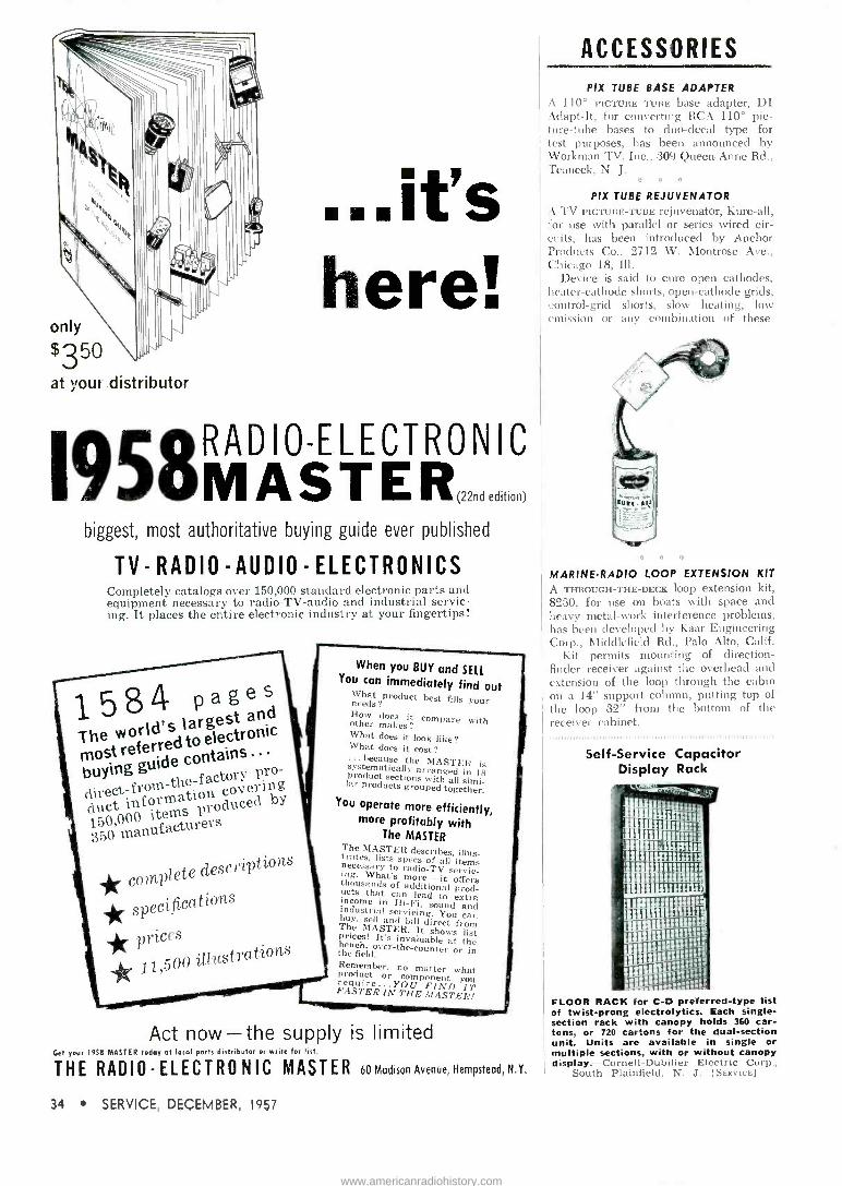
...it's here!
only
$350 at your distributor
19S8MRADIOELECTRONIC AST E R,,,., o.
biggest, most authoritative buying guide ever published
TV -RADIO -AUDIO -ELECTRONICS Completely catalogs over 150,000 standard electronic parts and equipment necessary to radio -TV -audio and industrial servic- ing. It places the entire electronic industry at your fingertips!
1584 pged es
The world's large
most referred to electronic
buying gui de actcrvepng ro -
duct information 150,000 items produced 'oduced
by
350 manufacturers
* complete descriptions
* specifications
* prices
* 11,500 illustrations
When you BUY and SELL You can immediately find out
What product best fills your needs? How does it compare with other makes? What does it look like? What does it cost? ... because the MASTER is systematically arranged in 18 product sections with all simi- lar products grouped together.
You operate more efficiently, more profitably with
The MASTER The MASTER describes, illus- trates, lists specs of all items necessary to radio -TV servic- ing. What's more - it offers thousands of additional prod- ucts that can lead to extra income in Hi-Fi, sound and industrial servicing. You can buy, sell and
The bill
MASTER.Itdshows from prices! It's invaluable at the bench, over-the-counter or in the field. Remember, no matter what product or component you require...YOU FIND IT FASTER IN THE MASTER!
Act now-the supply is limited Get your 1918 MASTER today at local ports distributor or write for list.
THE RADIO -ELECTRONIC MASTER 60 Madison Avenue, Hempstead, N.Y.
34 SERVICE, DECEMBER, 1957
ACCESSORIES
PIX TUBE BASE ADAPTER A 110° PICTURE TUBE base adapter, DI Adapt -It, for converting RCA 110° pic- ture -tube bases to duo -decal type for test purposes, has been announced by Workman TV, Inc.. 309 Queen Anne Rd., Teaneck, N. J.
a o *
PIX TUBE REJUVENATOR A TV PICTURE -TUBE rejuvenator, Kure -all, for use with parallel or series wired cir- cuits, has been introduced by Anchor Products Co., 2712 W. Montrose Ave., Chicago 18, Ill.
Device is said to cure open cathodes, heater -cathode shorts, open -cathode grids, control -grid shorts, slow heating, low emission or any combination of these.
MARINE -RADIO LOOP EXTENSION KIT
A THROUGH -THE -DECK loop extension kit, 8230, for use on boats with space and heavy metal -work interference problems, has been developed by Kaar Engineering Corp., Nliddlefield Rd., Palo Alto, Calif.
Kit permits mounting of direction - finder receiver against the overhead and extension of the loop through the cabin on a 14" support column, putting top of the loop 32" from the bottom of the receiver cabinet.
Self -Service Capacitor Display Rack
a;erUEfj
}.i ITI 111 iTIITíÌiTlll íiT.
Tl
i 1111111 TTT
III
ll El1;
FLOOR RACK for C -D preferred -type list of twist -prong electrolytics. Each single - section rack with canopy holds 360 car- tons, or 720 cartons for the dual -section unit. Units are available in single or multiple sections, with or without canopy display.-Cornell-Dubilier Electric Corp.,
South Plainfield, N. J. [Seavics]
www.americanradiohistory.com

COMPONENTS MINIATURE WIRE TANTALUM
CAPACITORS MINIATURE WIRE TANTALUM capacitors, WT, for low -voltage do applications, such as transistor audio amplifiers, have been developed by Aerovox Corp., New Bedford, Mass.
Operating temperature range is from -20° C to +50° C. Of polar construction, capacitor case and attached lead form the cathode terminal and are available in insulated or non -insulated construction. Anode tantalum wire extends through teflon bushing to which a solder lead is attached. Welded connection is encap- sulated in a thermosetting resin. Units are color -coded to indicate capacitance and voltage ratings. [SERvicE]
0 0
PLUG -SCREW MOUNT SILICON RECTIFIER
A SILICON RECTIFIER that may be screwed onto the chassis or plugged into a holder has been introduced by the rectifier divi- sion of Audio Devices, Inc., 620 E. Dyer Rd., Santa Ana, Calif.
Hermetically -sealed, unit is rated at 750 ma at 400 v. [SERVICE]
° 0 0
PUSH-PULL SWITCH VOLUME CONTROL
AN AC LINE switch, with push-pull action, is now available on volume controls manufactured by P. R. Mallory and Co. Inc., 3029 E. Washington Street, Indianapolis 6, Ind.
The line circuit closes when the control shaft is pulled out, opens when the shaft is pushed in. Volume, it is said, always remains at proper level because the set is turned on at the same volume at which it is turned off.
The push-pull switch uses a floating ring contact action that gives protection against overloads. It is available on single and dual Mallory controls in ratings to match original controls in popular radio and TV seis.
Capacitor Contest Winners
GRAND PRIZE WINNERS in Pyramid's Serviceman's twist -mount capacitor con- test who won a weekend in New York plus a cash award. Left to right: Mr. and Mrs. Sidney White, Cross Island Elec- tronics, Bellrose, N. Y., and Mr. and Mrs. R. Berthold, Springfield Gardens, N. Y. Berthold won the grand prize. As Bert - hold's distributor, White, manager of Cross Island Electronics, received a dup-
licate grand prize. [SERVICE]
NEW improved model
26 RUGGED
PRINTED
CIRCUIT!
TRADEMARK
FG ZOOMA. Rn;Mum
...the VOM that outsells all others combined
MANY NEW FEATURES MAKE THE 260 MORE VALUABLE THAN EVER!
POLARITY REVERSING SWITCH 50 MICROAMPERE -250 MILLIVOLT RANGE
EASIER -TO -READ SCALES
POPULAR DBM RANGES
r RUGGED PRINTED CIRCUIT
LESS CIRCUIT LOADING
FULL -WAVE BRIDGE RECTIFIER SYSTEM
ALL COMPONENTS EASILY ACCESSIBLE
IMPROVED FREQUENCY RESPONSE IN A. C. MEASUREMENTS
See it at your Distributor, or write
SIMPSON ELECTRIC COMPANY 5200 West Kinzie Street, Chicago 44, Illinois
Phone: EStebrook 9-1121 In Canada: Bach -Simpson Ltd., London, Ontario
WORLD'S LARGEST MANUFACTURER OF ELECTRONIC TEST EQUIPMENT
Rdif S'unpa I OVER 50 YEARS
y .,011,0141110,011,5
SERVICE, DECEMBER, 1957 35
www.americanradiohistory.com

A Report on TV Tubes Designed for Wide -Angle Chassis
. . . Replacements for Color and B -W TV Receivers . . .
Hi-Fi Audio Tubes ... Auto -Radio 12-V Tubes
111111111111114111111111111111111111111111.1111111111111. ,1111111111111111111.1111111.111111.111.6.1...31111, IIIIIII11111H,...11111, ,1111111H1111111111111,11111111,1,1111111,11,11111111111111111,1,1,1,,,1111111111111111111111111111111111111111
THREE NEW -TYPE tubes' have been developed for wide-angle TV re- ceivers.
One, an octal -based T-9 high per- veance, low -mu triode (6CK4) has been designed for use as a vertical deflection amplifier.
The tube features a maximum plate dissipation of 12 watts and an average cathode current of 100 ma.
Intended for receivers with high accelerating potentials, the 6CK4 is
said to incorporate a plate capable of conservative operation at rated dis- sipation. At the same time, the base pin has been isolated electrically to withstand high pulse plate voltages.
The others are 9 -pin (T -63k) minia- ture beam power pentodes (6DW5 and 12DW5), also for use in vertical - deflection amplifiers.
Both tubes, capable of operation at relatively low B supply voltages, are characterized by high zero -bias plate current. Double base pins for the number -1 grid permit cooler opera- tion. An electrically isolated plate pin is said to help each tube withstand high pulse plate voltages.
Type 12DW5 features controlled heater warmup time for operation in receivers utilizing a 600 -ma series heater string; the 6DW5 has been de- signed for operation in conventional transformer sets.
B-W/Color-TV Replacements
Two TUBES, the 6BJ8 and 5V3, are now available as replacements for b -w and color -TV chassis.'
The 6BJ8 is a heater -cathode type medium -mu triode and double diode
'Sylvania. 'Raytheon.
miniature designed for use as a phase splitter, phase comparator and hori- zontal -deflection oscillator. It has a 600 -ma heater rating.
The 5V3 is a filament type, high - vacuum, double diode. Its principal application is as a full -wave rectifier in the power supply of color -TV re- ceivers and in other equipment of high current requirements.
Sharp -Cutoff Twin Pentodes
SHARP -CUTOFF TWIN pentodes of the 9 -pin miniature type (3BU8 and 6BU8), intended for use in sync cir- cuits and automatic -gain -controlled amplifier circuits of TV receivers, have been announced.'
In such receivers, one pentode unit performs the function of combined
TWELVE -VOLT miniatures designed to operate directly from an automobile's battery -generator supply (left to right): 12.18, a 9 -pin audio driver; 12ÁD6, a 7 -pin pentagrid converter; 12CX6, a 7 -pin rf pentode; 12CNS, a 7 -pin if amplifier; 12F8, a 9 -pin double diode pentode audio driver, and 12EL6, a 7 -pin double diode triode
audio amplifier-Sylvania. [SEavice].
sync separator and sync clipper; the other pentode unit serves as an auto- matic -gain -controlled amplifier.
Each utilize a common cathode, grid 1 and 2. In addition, grid 1 and 3 of each type have a separate base - pin terminal and may be used inde- pendently as a control electrode.
The 3BU8 has been designed for use in receivers employing series heater -string arrangements and is like the 6BU8 except that it has a 3.15- v/.6 -a heater.
Miniature Beam Power Tube
A BEAM -POWER tube (6973) of the 9 -pin miniature type (6.3 v at 450 ma), for use as an output tube in high-fidelity audio equipment, is now available.'
Design is said to feature linear operation over a wide range of power, high power sensitivity and stability.
20 -Watt Output
In push-pull class AB, audio ser- vice, two 6973's, operating at a plate voltage of 350, grid -2 voltage of 280, and fixed grid -1 voltage of -22, can deliver, it is claimed, a maximum - signal power output of 20 w with a
total harmonic distortion of 1.5 per cent.
Tube has double base -pin connec- tions for both grid 1 and 2 to provide cool operation of these grids and to minimize grid emission. Cool oper- ation of both grids also permits use of relatively high values of grid -cir- cuit resistance to reduce driving power.
12 Volt Auto -Radio Tube
A MINIATURE 9 -PIN combined twin di- ode and space -grid tetrode (12DL8) with independent unipotential cath- odes, has been announced for auto radios.'
Detector -Amp Application
The diode section is intended for use as a detector, while the tetrode section, a power amplifier, has been designed to drive transistor audio out- put stages. All tube elements, includ- ing the heater, operate at a potential of 12 v, obtained directly from the automobile battery.
Miniature Audio Pentode
Also recently announced for audio is a 6BQ5 miniature pentode.'
'RCA.
36 SERVICE, DECEMBER, 1957
www.americanradiohistory.com

Pr.
Picture of a smart TV technician making a dollar a minute
on his way back from lunch /
"Naturally... it's the GOLD Twilight Antenna
by H7neyand Co. Dept. E-12
BURLINGTON, IOWA"
Semiconductor Developments Latest Information on New Types of Transistors and Diodes
A PNP GERMANIUM -ALLOY high -volt- age power transistor has been added to the renewal line of Sylvania Electric Products Inc.
The transistor, type 2N296, has been designed for high -voltage power amplifier and switching applications in which 25 to 60-v supply voltage is required.
Features welded hermetic seal con- struction and has a collector current of two a.
Junction IF Amp Transistors)
GERMANIUM -ALLOY junction transis- tors of the pnp type (2N409 and flexible -lead version, 2N410) have been designed for 455-kc if amplifier applications in transistorized portable radios.
Both are said to feature a power gain of 31.2 db in a common -emitter type of fixed circuit that sacrifices gain to provide stability and interchange- ability. The neutralizing network of this circuit is fixed. The amount of gain sacrificed is minimized by manu- facturing controls on the transistor parameters, particularly the para -
1 RCA.
111111111111111111,11111111,11111111111 II
meters responsible for system feed- back.
These transistors are hermetically sealed and utilize a metal case.
Junction Transistors for Convertersf
To MEET THE REQUIREMENTS Of con- verter and mixer -oscillator applica- tions in the AM broadcast band, pnp junction transistors (2N411 and flex- ible -lead type 2N412) have been developed.
In a common -emitter type of fixed circuit, these transistors are claimed to have a conversion power gain of 32 db at 1 mc.
These transistors are also hermeti- cally sealed in a metal case.
HF Drift Transistors
DRIFT TRANSISTORS (2N370, 2N371, and 2N372) of the germanium pnp type are now available for all -wave battery -portables. The 2N370 is in- tended for rf amplifier service, the 2N371 for oscillator service, and the 2N372 as a mixer.
The 2N370, 2N371, and 2N372 look alike. They are hermetically sealed in metal cases, have a diameter of .360" a body height of .375" and
four flexible leads. One of the leads provides shielding to minimize inter - lead capacitance and to minimize coupling to adjacent circuit compon- ents, of primary importance in hf applications.
Silicon Rectifiers
A LINE of diffused silicon rectifiers (M14) has been announced by Motorola.
The rectifiers are available in peak inverse ratings of 100 through 600 y with average forward currents of 500 ma, and with the case common to either cathode or anode.
Three silicon rectifiers have also been announced by Sarkes-Tarzian.
Two are high -current types, rated at 150 and 200 amperes (types X and W) and the third type is a high -volt- age half -wave rectifier (S-5033) that can be used as a direct replacement for several octal based rectifier tubes.
Silicon Junction Diodes
A SUBMINIATURE SILICON JUNCTION
diode, 1N658, has been brought out by General Instrument Corp.'s semi- conductor division through its Radio Receptor subsidiary. The new diode has been designed for computer, com- munications and general circuit re- quirements.
The 1N658 features a forward voltage drop under 1 at 100 ma, with a .3-usec reverse recovery. Peak inverse voltage is 120, with a
reverse leakage of .05 ua at -50 v.
SERVICE, DECEMBER, 1957 37
www.americanradiohistory.com

TEST INSTRUMENTS
STOP CB WITH C -D
I r
°("o:; CORNELL-DUBILIER CAPACITORS SOUTH PLAII 'F ELD. N. J.; NEW BEDFORD. WORCESTER B CAMBRIDGE. MASS.; PROVIDENCE B HOPE VALLEY. R. I.; INDIANAPOLIS. IND, SANFORD, FUOUAV SPRINGS & VARINA. N. C. VENICE. CALIF.; & SOB.: THE RADZART CORP., CLEVELAND. OHIO; CORNELL-DUBILIER ELECTRIC INTERNATIONAL, N. Y.
'CALL BACKS ARE COSTLY. Cornell-Dubilier are specialists in ELECTROLYTICS for replacement service. The familiar C -D Trademark has been the mark of outstandingly superior quality for over 47 years. Every style, size, rating and char- acteristic of electrolytic capacitor is produced in C -D's own network of plants. From the tiny "finger -nail" size "ELECTO- MITE"®to the compact "BLUE BEAVER"®tO the long -life "uP" C -D ELECTROLYTICS have earned their great popularity be- cause they are consistently MADE BETTER to LAST Say C -D when you buy ELECTROLYTICS-be particular. Write for Catalog 200D -3E to Dept. S-12. Electric Corp., South Plainfield, New Jersey.
stop call backs... insist on
GRID CIRCUIT TUBE TESTER
A GRID CIRCUIT tube tester, GCT-8, for checking critical -control grid condition of tubes, has been introduced by the Seco Manufacturing Co., 5015 Penn Ave. S., Minneapolis, Minn.
Said to provide as many as 11 simul- taneous tests on a typical pentode such as the 6AU6. Presence of any one or a combination of the following faults, it is claimed, will register as bad on an elec- tron -eye indicator: control grid emission, grid -to -cathode shorts, gaseous condi- tion, cathode -to -heater shorts, grid -to - heater shorts, grid -to -plate shorts, plate - to -heater shorts, grid -to -screen shorts, screen -to -heater shorts, heater -to -sup- pressor shorts and grid -to -suppressor shorts. [SERVICE]
TRANSISTOR CHECKER A TRANSISTOR CHECKER, TRC4, which also tests crystal diodes and selenium rectifiers, has been developed by Service Instruments Corp., 171 Official Rd., Addison, Ill.
Tests for opens, shorts, current gain and leakage on transistors and forward - to -reverse currents on crystal diodes and rectifiers. [SERVICE]
STABILIZED VTVM WIDE -BAND VIDEO AMP
A STABILIZED VTVM, Microlter, without feedback, said to afford wide -band ac- curacy to 50 mc, has been announced by Kay Electric Co., Maple Ave., Pine Brook, N. J.
Unit permits measurement of low-level rf signals down to 250 tic. I las a 7 -posi- tion switch which provides full-scale steps of 1, .3, .1, .03, .01, .003 and .001 e. Instrument can also serve as a wide -band video amplifier with a maximum output of approximately .25 y at 75 ohms and gains of up to 40 db. Input capacitance is 5 mmfd. [SERVICE]
C * D
MULTI -PURPOSE TEST SET
A TRANSISTORIZED MULTI -PURPOSE port- able test set, TU546, to facilitate aligning and testing of mobile and base -station transmitters and receivers, has been an- nounced by Motorola Communications and Electronics, Inc., 4501 W. Augusta Blvd., Chicago 51, Ill.
Unit includes a built-in PM speaker for audio reception. An audio -frequency electronic voltmeter permits measure- ment of oc voltages below 2 e. An if oscillator circuit provides crystal -con- trolled if frequencies between 280 kc and 13 mc. A 455-kc crystal is included for alignment of the last if and dis- criminator stages.
Can be used to measure A+ and B+ in both receivers and transmitters, grid and plate current in the transmitter, rela- tive field strength of radiated signals, transmitter power output and receiver quieting sensitivity. A transistorized rf peaking generator, available as an acces- sory, provides crystal -controlled rf output for rf peaking of 25-54, 144-174, 450- 470, and 890-960 me receivers. [SERVICE]
38 SERVICE, DECEMBER, 1957
www.americanradiohistory.com
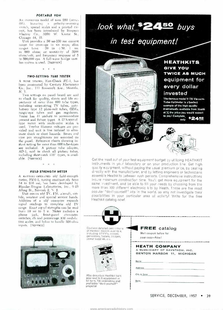
PORTABLE VOM
AN IMPROVED model of vom 260 (series III), featuring a polarity -reversing switch, spread scales and a printed cir- cuit, has been introduced by Simpson Electric Co., 5200 W. Kinzie St., Chicago 44, Ill.
Unit provides a 50 ua-250 my current range for coverage in six steps; dbm ranges from -20 to +50, 1 nit in 600 ohms; ac sensitivity of 5000 ohms/volt; and frequency response of 5 to 500,000 cps. A full -wave bridge recti fier system is used. [SERvIcE]
* º O
TWO -SETTING TUBE TESTER
A TUBE TESTER, Fast -Check FC -1, has been announced by Century Electronics Co., Inc., 111 Roosevelt Ave., Mineola, N. Y.
Two settings on panel board are said to check for quality, shorts and life ex- pectancy of more than 600 tube types, including series -string TV tubes, auto - battery type 12 plate -volt tubes, OZ4's, magic -eye tubes and gas regulators. Tester has 41 sockets to accommodate present and future types. A D'Arsonval- type meter with multi -color scales is used. Twelve filament voltages are pro- vided and unit is line isolated to elim- inate shock or short hazards. Seven and nine pin straighteners are mounted on the panel. Reference charts showing in- stant setting for more than 600 tube -types are included. A picture tube adapter, AD -1, said to check all picture tubes, including short -neck 110° types, is avail- able. [SEnvIcE]
e * º
FIELD STRENGTH METER
A BATTERY -OPERATED vhf field -strength meter, FSM-1, tuning continuously from 54 to 216 mc, has been developed by Blonder -Tongue Laboratories, Inc., 9-25 Alling St., Newark 2, N. J.
Unit covers vhf TV, FM, aircraft, mo- bile, amateur and special service bands. Addition of a uhf converter expands signal readings to complete uhf TV range. Exact signal strengths can be read from 10 uv to 3 v. Meter includes a phone jack, front -panel attenuator switches, db and percentage AM modula- tion scales, and balun to handle 300 -ohm inputs. [SERVICE]
HEATHKITS GIVE YOU TWICE AS MUCH equipment for every dollar invested
The famous model V -7A Vacuum - Tube -Voltmeter is a perfect example of the high -quality Instruments available from Heath at ''A the price you would expect to payl Complete
only $240
Get the most out of your test equipment budget by utilizing HEATHKIT instruments in your laboratory or on your production line. Get high quality equipment, without paying the usual premium price, by dealing directly with the manufacturer, and by letting engineers or technicians assemble Heathkits between rush periods. Comprehensive instructions insure minimum construction time. You'll get more equipment for the same investment, and be able to fill your needs by choosing from the more than 100 different electronic kits by Heath. These are the most popular "do-it-yourself' kits in the world, so why not investigate their possibilities in your particular area of activity! Write for the free Heathkit catalog now!
Contains detailed descriptions of Heathkit models available, including VTVM's, scopes, generators, testers, bridges, power supplies, etc.
Also describes Heathkit ham gear and hi-fi equipment in kit form. 100 interesting and profitable "do-it-yourself" projectsl
--401141 FREE catalog Mail coupon below for
your copy-Now!
HEATH COMPANY A SUBSIDIARY OF DAYSTROM, INC, BENTON HARBOR 11, MICHIGAN
Name
Address
City & Zone
State
SERVICE, DECEMBER, 1957 39
www.americanradiohistory.com

. . . another
MALLORY service -engineered
product
Zigewila 1 prove MALL
"GEMS"
To demonstrate how well Mallory "Gem" tubular capacitors resist moisture, we put some in plastic tubes filled with water. Months later, their internal resistance remains unchanged ... proving there has been no moisture absorption.
Sure, you don't expect to submerge the capacitors you install. But when you're looking for top performance, even under the toughest humidity- always ask for Mallory "Gems."
Get your stock today from your Mallory distributor. He carries them in all popular ratings for by-pass and coupling applications.
P.R. MALLORY fì CO. Inc.
P. R. MALLORY L CO. Inc., INDIANAPOLIS 6, INDIANA
Capacitors Vibrators
Contrail Switches
Resistors Rectifiers
_ Power Supplies Filters Mercury and Zinc -Curb.
Batteries
Tape Recorder -Playback
(Continued from page 19 )
ing level may be set before the tape is set into motion. To record, it is necessary to depress and latch both the monitor and play pushbuttons simultaneously. This avoids erasure of prerecorded tapes if one pushbutton were accidently depressed.
THREE BASIC TYPES of microphones 11 to r) bidirectional, unidirectional, and omnidirectional, which can be used for tape recording. All three can be mounted on table stands as pictured, or placed on floor stands. The omnidirectional unit is
particularly suited for use as a hand - carried unit and can be worn as a lavalier microphone.-Shure Brothers, Inc., 222
Hartrey Ave., Evanston, Ill. [SERVICE].
POLYSTYRENE container for tape which can be stacked or hung on a wall by means of a dovetail slot in the back and a fitted strip. Package also includes a tape - time ruler to permit accurate m
ment of elapsed and remaining time Ferrodynamics Corp., Lodi, N. J. [SERVICE].
40 SERVICE, DECEMBER, 1957
www.americanradiohistory.com

TV Power Transformers (Continued from page 15)
steel plate welded to one end shell (Fig. 1-p. 14) , and on a horizontal chassis it uses two mounting brackets similar to those used for other trans- formers. In the original horizontal mounting these mounting brackets were larger than usual and were pro- vided with vent holes because the entire fin assembly was above chassis. The present horizontal mounting (Fig. 3-p. 15) uses short brackets and the fins protrude through holes in the chassis to take advantage of the cooler air available from openings in the cabinet bottom.
Service Notes (Continued from page 25)
dangerous, because while it would not burn out, the entire set would be ex- posed to overloads.
Such burnouts indicate excessive line -voltage -surge conditions that must be compensated for if components are to operate within their rating. In such instances there's need for a line -volt- age regulator or ballast that can be installed in conjunction with the re- placement. The ballast actually com- pensates for line -voltage variations over a considerable range, thereby providing extra protection.
111 1,,111111,111 1 1111 1 111 I I 1111111111111111111
TV Antennas Continued from page :32)
using a cheap rabbit -ear antenna and attaching two receivers to one an- tenna.
What is the answer to all of this? The Service Man is the answer. He
has to do a selling job. He has to educate the set owner into a top qual- ity installation of top quality antennas. If he doesn't, the primitive do-it-your- selfer will continue to be the bane of his existence.
'A previous Snyder investigation found that the average set owner purchased up to four dollar -type antennas within two years because of dissatisfaction with reception.
Join the MARCH OF DIMES
new profits available in hi-fi servicing
and
is Hi-Fi Service
Headquarters Hi-Fi servicing is a booming new profit source for you, and WALSCO
-always your completely depend- able supplier for radio -tv service products-is ready with all the things you need to tap this grow- ing field.
MOLDED -ON CABLES AND CONNECTORS
Look for this WALSCO dis- play at your distributor. A
complete assortment for your every need. Dozens
of tenite shielded cables with phono pin plugs, jacks, phone plugs and alligator clips in a wide variety of combinations-in lengths up to 72".
!x2400 (36") $1.05 List
2418 (10") $3.25 List
PHONO -RECORDER BELTS AND DRIVES
Webcor Drive Wheel #1463-$2.50 List
A complete replacement source for Ampro, Collaro, Crescent, Garrard, Pentron, Revere, RCA, VM, Webcor and every other standard changer and recorder.
RCA Idler Wheel #1432-51.00 List
HI-FI CHEMICALS
"No -Slip" for cords and pulley belts 260-01-60c List
The latest WALSCO cata- log . from your distribu- tor, or write for it today.
A full line of special chem- icals for Hi-Fi servicing- to make your job easier and faster.
RH Recording Head Cleaner #93-01-95c List
WALSCO ELECTRONICS MFG. CO. A division of Textron, Inc.
108 west green street rockford, illinois
SERVICE, DECEMBER, 1957 41
www.americanradiohistory.com

service engineering
INDUSTRIAL
ELECTRONICS
1
)i°oa MNI1 ( *Ate 17'*T+S.1 wwlwa awL» cectl 18888 cc cc ...... .
a:-...
:C
gem
r r- 'OW ,... poor
Servicing Carrier -Current Wireless Intercoms
WIRELESS INTERCOM systems consist of two or more fixed two-way units which operate at low radio frequen- cies, with signals being conveyed over the power lines via a carrier cur- rent. Each unit consists of a simple radio receiver and radio transmitter. As in wired - intercom systems, the loudspeaker serves both as a loud- speaker and microphone.
Installation is simple. Wires for conveying audio signals from one unit to another are not required. Instead, the audio signal is used to modulate a radio transmitter. The rf signal is fed over the power lines and the receiver in the second intercom unit demod- ulates the rf signal. When more than two intercom units are used, party - line communication results. In other words, speech and sounds picked up by unit A, for example, are picked up by units B, C, and D. Likewise, when unit B is set to the talk position, units A, C, and D intercept signals being transmitted by unit B.
In wired systems, of course, it is possible for a person at unit A, if it is a master unit, to select individually
units B, C, and D. In wireless systems which operate on one frequency, all intercom units are called simultan- eously. Of course, it Nvould be possible to provide selective calling of slave units from a master unit by providing the master unit with a means for changing the transmitter frequency and by tuning each of the slave units to an individual frequency. However, this is seldom done and therefore most wireless intercom systems operate on a party -line basis.
While, theoretically, all that is re- quired to install a wireless -intercom system is to plug into the line, trouble may be encountered due to losses in the power lines. Some equipment is provided with an extra terminal which is connected to ground or directly between units, as illustrated in Fig. 1. A wire may be connected to the terminal on each unit so that all units in a system are directly connected by the wire and indirectly through the power line. Optionally, but with some- what more transmission loss, the terminal of each unit may be grounded to the screw that holds the
soi SIC
O S VINE I
POW SEAV SW
VIAE
ONP VOL
OWENSVCON1N
LISTEN ITSAC
1/1250 12AX7 FEG YS Y.00OSS5OOO 15M 500 FD 0
CNM52MNEO^ MOFO - _L
4.1 IMEG I
MEG I __ I - ff
_ O41 1 MFp
B- J
470 00.6,150
MF.-
100,000 MMFO
B-
MMFD 10.000
20°0430s0
INSI
LUME 5000,50
B-
r
10,000 OHMS
330000
5000 070 MMFD MOFO
5005 1000 MOFO
10,000 MNIFD
1
J
FD
INA 47,000 OHMS
E alô aio e
91` SEXO
175 AC
oÑús 35W4
D0,o00
150
lo,000 0HM5 zm
OHMS
ú 0 B-
4100
v. OHMV
((
I MFD MZiD )I SP" WIC
B-
1
0000 7,1 LMFo
h ,
TALK/LISTEN SWITCH SHORN IN
LISTEN (COMM POS111ON
cover plate on the power receptacle or to some other ground.
In one type of wireless intercom' (Fig. 2.) , the direct -wire or ground terminal leads to a tap on the receiver tuning coil. A switch is provided for selection of either the two -wire or three -wire transmission arrangement. When installing wireless - intercom equipment, regardless of whether the two -wire or three -wire hookup is used, the power plug at each unit should be plugged in one way and then reversed to determine which will provide the most satisfactory results.
The Fig. 2 wireless -intercom circuit features a grid -leak type detector tuned to 175 kc and a two -stage audio amplifier. A 12AX7 dual triode is used as the detector and first audio stage. And a 5005 audio power amplifier functions as the rf oscillator or trans- mitter, also tuned to 175 kc.
A unique feature of the intercom shown in Fig. 2 is the squelch circuit which silences the receiver until an rf signal is picked up from another unit. A part of the intercepted rf sig- nal is fed through an rc filter network to a 1N51 diode. In the presence of an rf signal of sufficient amplitude, a positive voltage is built up across the diode which reduces the bias on the first audio stage permitting it to amplify incoming signals. When no signal or a very weak signal is present, the first audio stage is cut off by the biasing action of the cathode -resistor network. Bias is reduced when the unit is set to send so that the first audio stage will amplify. In send position, the stage referred to as the first audio stage actually becomes the second stage which grid modulates the 5005 oscillator stage.
While the procedure for aligning wireless intercom units may differ among various makes, the general principles described here are applic- able. To align the receiver an rf sig- nal generator tunable to 175 kc is
(Continued on page 45)
(Above) FIG. 1: BLOCK DRAWING of a typical
link between intercom units.
(Left) FIG. 2: SCHEMATIC of Bennett model 100
wireless intercom.
'Bennett Laboratories, Inc., Redwood City, Calif.
42 SERVICE, DECEMBER, 1957
www.americanradiohistory.com

The foremost name in
automotive loudspeakers !
Three-way universal terminal- ead arrangement is especially corrven- ient. Tip jacks fit Ford -Lincoln- Mercury rear seat pin terminals; twin lead for splicing to front sea' )lug cable; solder lugs for general use.
Nominal Size
Inches Model
No.
Magnet Weight* Ot. nces
BURTON BROWNE ADVERTISING
PROVED IN 10/000/000 CARS AND TRUCKS!
Jensen WORLD'S MOST RUGGED
AUTOMOTIVE SPEAKERS
CONCERT SPECIAL OVAL GROUP Jensen designed this extra ruggedized Special Oval Group at the request of one of the largest automobile manufacturers. Millions of units with years of service in truck and passenger vehicles have established the complete dependability of these speakers for use as replacements wherever 6 x 9 and 5 x 7
units are required. Not to be compared with conventional ovals, they are up to 3 times as resistant to housing distortion due to mounting strains and vehicle vibration, maintain alignment indefinitely in specially oversized gaps, withstand severe overloads, are immune to weather and temperature changes. Efficient magnetic structure design, using DP -Alnico 5 magnets, has made possible shallow construction, virtually universal in complying with crowded installation conditions.
New high fidelity models will give superior wide range performance and added power handling capacity for a
noticeable improvement in auto radio sound quality.
VIKING For lowest cost, combined with rugged compactness, Jensen VIKING Series ovals fill the bill in automotive and other replac:ment services. Features include a completely enclosed magnetic structure, with precision locked -in alignment and new high efficiency DP -Alnico -5 magnet. Heavy gauge rigid housing. Solder lug terminals. One model in each 5" x 7" and 6" x 9' sizes handles 90% of your oval speaker requirements.
CONCERT SERIES-SFECIAL OVAL GROUP
Imped. Ohms
Voice Coil Power Watts
Dia. Inches
Dimensions, Inches
H. & W. Depth Baffle
Opening List
Price 5x7 5x7 6x9 6x9 6x9
5x7 6x9
P57 -U 1.73t 3.2 8.0 1 5 x 7'/4 2 1/2
P57 -TX§ 25$ 3.2 9.0 1 5 x 71/4 2'3/16 ,
P69 -U 1.73t 3.2 9.0 1 61/4 x 91/4 3s P69 -T 25$ 3.2 10.0 1 63/4 x 9'/s 35/ió
P69 -TX§ 2.5t 3.2 10.0 1 63/s x 91/4 35/t6
57-J9 69-J9
1.47 1.47
3.2
3.2
VIKING SERIES
6.0 7.5
3/4
3/4
5 x7'/4 6 3/a x 91/4
29/1
215/t6
4'/4 X 61/4
5'/a x 81/4
$7.20 8.35 7.80 8.65 8.95
5.85 6.50
§High Fidelity Model. *All Magnets DP Alnico 5. tPerformance Equivalent to RETMA 2.15 oz. $Perfo-mance Equivalent to RETMA 3.16 oz.
Send for your free copy of Data Sheet 167.
enVeii MANUFACTURING COMPANY 6601 South Laramie Ave., Chicago 38, Illinois
vision of The Muter Co. In Canada: J. R. Longstaffe Co., Ltd., Toronto
In Mexico: Radios Y Television, S.A , Mexico D.F.
SERVICE, DECEMBER, 1957 43
www.americanradiohistory.com

ADMIRAL ALLEGRO AIRLINE AM
CAL TECH CAPEHART FARNSWORTH
CROMWELL DYNAVOX ELECTRONIC GUILD RADIO HALLICRAFTERS HEA
OLYMPIC PACIFIC MERCURY PACK/ SEARS ROEBUCK SENTINEL SONIC C
SYMPHONIC
WILCOX GAY
CALIFONE
CRESCENT IND
STEELMAN
MOTOROLA
RCA VICTOR
SYLVANIA S
WEBCOR, INC. WILCOX GAY
A.M.C. BIRC CALIFONE CAL
CORONADO CRESCENT INDUSTRIES
FANON GRANCO GROSSMAN GL
LION MAGNAVOX MOTOROLA M
PHONOLA RCP
STROMBERG C
SYMPHONIC
WILCOX GAY
CALIFONE
CRESCENT IND
GRANCO GR
R ROLAND
SYLVANIA
OR, INC. W
A.M.C. BI
ORONADO C
EMERSON
HOFFMAN
;KARD-BELL NEL SONIC
TELEFUNKEN
ADMIRAL <
CAPEHART Fo
CROMWELL
GUILD RADIC
MOTOROLA LYMPIC PA(
RCA VICTOR SEARS ROEBI
SYLVANIA SYMPHONIC TRAV-LER
EBCOR, INC. WILCOX GAY ZENI
M.C. BIRCH CALIFONE CAL T
ONADO CRESCENT INDUSTRIE V -M WATERS CONLEY
A.M.C.
ECORDS CORONADO S EMERSON FANON GRA
FMAN ELECTRONIC CREATIONS PHILCO PHONOLA RCA VICT
AN STROMBERG CARLSON SYLV
ATONE V -M
AIRLINE RTH COLUM
X ELECTRO
ICRAFTERS
RCURY PAC
NTINEL SO
NKEN ULTRA
MIRAL ALLE
PEHART FARN'
ELL DYNAV
10 HALLICR
OLYMPIC PA
ROEBUCK SE
NIC TRAV-L:
AY ZENITH ALIFONE C
T INDUSTRIES
GRANCO
MAGNAVOX PHONOLA
AAN STROME
ATONE V -M
AIRLINE RTH COLUM
X ELECTROP
(CRAFTERS P
RCURY PAC
:NTINEL SON
S CONLEY W
tDOR ARTO
IRDS CORON
TIONS EME
HOFFMAN L
_L PHILCO
ELMAN STR
'-M WATERS
RUNE AMB
COLUMBIA
CTRONIC CRE
HEATH HOF
RCURY PAC
SONIC STE
FUNKEN ULT
AL ALLEGR
CAPEHART F
ELL DYNAV
N GUILD R
OLA M.V.M TOR ROLA
LSON SYLV
CONLEY
DOR ARTO
RDS CORO
TIONS EME
HOFFMAN L PHILCO
ELMAN STR
NKEN ULTRATONE V -M WATERS Hut,. AMBASSADOR ARTONE
RNSWORTH COLUMBIA RECORDS
EL DYNAVOX ELECTRONIC PACKARD-BELL HEATH
MANUFACTURERS HAVE SPECIFIED SONOTONE CERAMIC CARTRIDGES
FOR ORIGINAL EQUIPMENT Make the industry's choice your choice, Mr. Serviceman.
Replace with Sonotone Ceramic Cartridges for these good reasons:
1. You give your customer's phono- graph "original -equipment" bril- liance in sound-adding to your reputation. 2. You work with the standard car-
tridge of the industry-so you finish jobs easier and faster. 3. Sonotone Ceramics fill over 90% of your quality replacement needs -less cartridges for you to handle.
For list of manufacturers' set models using Sonotone Cartridges, write:
Electronic Applications Division
SON OTO N E® CORPORATION ELMSFORD, N. Y.
IN CANADA, CONTACT ATLAS RADIO CORPORATION, LTD., 5O WINGOLD AVE., TORONTO
Audio ( ('<ilinurd Jromn p(12i' i
1 )
from wobble. If tape hits reel inter- mittently coincident with noise, noise is probably caused by warped condi- tion of the tape reels.
To correct, the warped reel should be replaced. Care should be used in storing reels to prevent future warp- age; however plastic reels should be considered expendable.
In the second analysis of the prob- lem, if the reel is not warped, but wobble is noted, the probable cause is a high spot on one side of the reel spindle casting. This can be corrected by wrapping spindle with a cloth to prevent filings falling into the mechan- ism. High spot should be filed or sand- papered; to remove excess material retouch with lacquer.
Tools required are a file, piece of 00 sandpaper, small amount of lacquer, and a brush.
Amplifier Hiss'
A SMALL CONSTANT hiss is often emitted from an amplifier when the tone control is on full treble and vol- ume is at maximum. This is most ap- parent when no recorded sound is on tape.
This can be detected by depress- ing stop key, turning volume control up full and turning tone control to full treble; a low hiss may be heard.
Actually, this is not a defect. Any amplifier system capable of reproduc- ing a full range of tones will have a small amount of hiss most noticeable in the higher frequency range. The presence of a certain amount of amplifier hiss is actually one of the criteria of a playback music system capable of high-fidelity response.
COAXIAL THREE -ELEMENT speaker available in both 12" and 15" sizes. In these units, a dual diaphram affords If and mid - range performance, while a compression driver supertweeter covers the higher frequency range.-Type CX; Jensen Mfg. Co., 6601 S. Laramie Ave.,
Chicago 38, I11. [SERvIcE].
44 SERVICE, DECEMBER, 1957
www.americanradiohistory.com
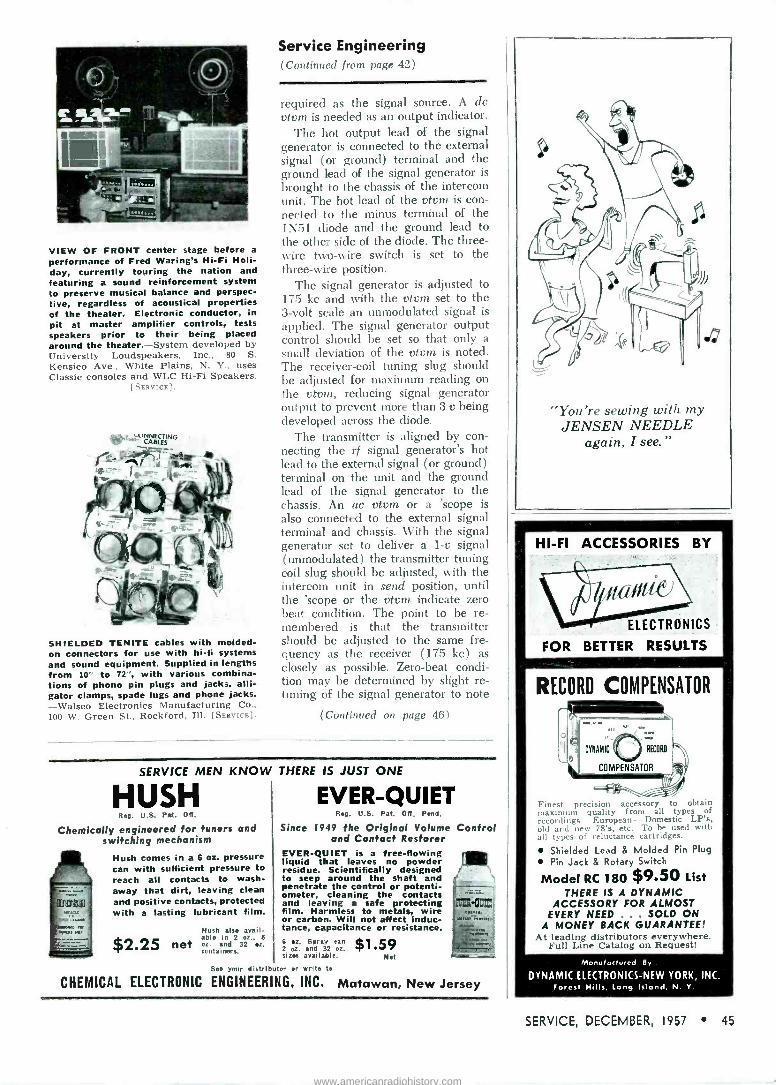
VIEW OF FRONT center stage before a
performance of Fred Waring's Hi-Fi Holi- day, currently touring the nation and featuring a sound reinforcement system to preserve musical balance and perspec- tive, regardless of acoustical properties of the theater. Electronic conductor, in pit at master amplifier controls, tests speakers prior to their being placed around the theater.-System developed by University Loudspeakers, Inc., 80 S. Kensico Ave., White Plains, N. Y., uses Classic consoles and WLC Hi-Fi Speakers.
[SERVICE].
wrvNKTING _ CABtES
.,
biRr .I
SHIELDED TENITE cables with molded - on connectors for use with hi-fi systems and sound equipment. Supplied in lengths from 10" to 72", with various combina- tions of phono pin plugs and jacks, alli- gator clamps, spade lugs and phone jacks. -Walsco Electronics Manufacturing Co., 100 W. Green St., Rockford, Ill. [SERvicEI.
Service Engineering (Continued from page 42)
required as the signal source. A dc vtvm is needed as an output indicator.
The hot output lead of the signal generator is connected to the external signal (or ground) terminal and the ground lead of the signal generator is
brought to the chassis of the intercom unit. The hot lead of the vtvm is con- nected to the minus terminal of the 1N51 diode and the ground lead to the other side of the diode. The three - wire two -wire switch is set to the three -wire position.
The signal generator is adjusted to 175 kc and with the vtvm set to the 3 -volt scale an unmodulated signal is
applied. The signal generator output control should be set so that only a small deviation of the vtvm is noted. The receiver -coil tuning slug should be adjusted for maximum reading on the vtvm, reducing signal generator output to prevent more than 3 v being developed across the diode.
The transmitter is aligned by con- necting the rf signal generator's hot lead to the external signal (or ground) terminal on the unit and the ground lead of the signal generator to the chassis. An ac vtvm or a 'scope is also connected to the external signal terminal and chassis. With the signal generator set to deliver a 1-v signal (unmodulated) the transmitter tuning coil slug should be adjusted, with the intercom unit in send position, until the 'scope or the vtvm indicate zero beat condition. The point to be re- membered is that the transmitter should be adjusted to the same fre- quency as the receiver (175 kc) as closely as possible. Zero -beat condi- tion may be determined by slight re- tuning of the signal generator to note
(Continued on page 481
SERVICE MEN KNOW THERE IS JUST ONE
HUSH Reg. U.S. Pat. Ott.
Chemically engineered for tuners and switching mechanism
Hush comes in a 6 oz. pressure can with sufficient pressure to reach all contacts to wash - away that dirt, leaving clean and positive contacts, protected with a lasting lubricant film.
$2.25 net Hush also avail- able in 2 oz.. 8 oz. and 32 oz. containers.
EVER -QUIET Reg. U.S. Pat. Off- Pend.
Since 1949 the Original Volume Control and Contact Restorer
EVER -QUIET is a free -flowing liquid that leaves no powder residue. Scientifically designed to seep around the shaft and penetrate the control or potenti- ometer, cleaning the contacts and leaving a safe protecting film. Harmless to metals, wire or carbon. Will not affect induc- tance, capacitance or resistance. 6 oz. Spray can 2 oz. and 32 oz. sizes available.
$1.59 Net
See your distributor sr Write to
CHEMICAL ELECTRONIC ENGINEERING, INC. Matawan, New Jersey
"You're sewing with my JENSEN NEEDLE
again, I see."
HI-FI ACCESSORIES BY
ELECTRONICS
FOR BETTER RESULTS
RECORD COMPENSATOR
o
Mell IX»
DYNAMIC ',{ ) RECORD
COMPENSATOR
Finest precision accessory to obtain maximum quality from all types of recordings - European - Domestic LP's, old and new 78's, etc. To be used with all types of reluctance cartridges.
Shielded Lead & Molded Pin Plug Pin Jack & Rotary Switch
Model RC 180 $9.50 List THERE IS A DYNAMIC
ACCESSORY FOR ALMOST EVERY NEED ... SOLD ON
A MONEY BACK GUARANTEE! At leading distributors everywhere.
Full Line Catalog on Request!
Manufactured By
DYNAMIC ELECTRONICS -NEW YORK, INC. Forest Hills, long Island, N. Y.
SERVICE, DECEMBER, 1957 45
www.americanradiohistory.com

HERE'S WHAT
O 18 Popular Values
OHandy, Convenient 18 Section Plastic Storage Case
Exceptional Value
YOU GET
63 High Stability ERIE Disc or Tubular Ceramicons
ORDER NOW. From Your
ERIE
DISTRIBUTOR
HERE'S WHAT YOU SAVE REGULAR PRICE
63 Piece ERIE Ceramicon Assortment $15.00 18 Section Plastic Case 1.75
Total Value $16.75
YOU PAY $10.65 YOU SAVE $ 6.10
MORE Acriv./ er/W
KESTER "RESIN --FIVE"
CORE
SOLDER
THE BEST FOR TV-RADIO WORK... EVERYTHING ELECTRICAL-Kester "Resin -Five" Core Solder is better and faster than any solder ever developed. It has an activated flux -core that does a perfect job on all metals including zinc and nickel -plate. The flux residue is absolutely non -corrosive and non-conductive.
Available in all practical Tin -Lead
Alloys; 40/60, 50/50 and 60/40 in
diameters of 342" 1'6", 34", 142' and others.
Printed Circuit Soldering On Copper -etched boards use 60% Tin -40% Lead Alloy .. for those that are Silver -surfaced vse 3% Silver -61',2% Tin - 351,2% Lead
KESTER SOLDER COMPANY 4248 Wrightwood Avenue, Chicago 39, Illinois Newark 5, New Jersey, Brantford, Canada
Service Engineering (Continued from page 45)
the point where the two signals are out of phase with each other and cause a minimum output indication. When a vtvm is used, it should be set on the 3-v scale.
The intercom illustrated was de- signed to produce an rf signal of 2 watts; the receiver delivers 2 watts of audio to the speaker with maximum useable signal applied. While it is possible to build wireless intercom systems which transmit a stronger sig- nal and hence would have greater range, there is the possibility that the signal would radiate further from the power lines than now permitted by FCC rules.
Still another adaptation of wireless intercom is a one-way unit; a wireless microphone which is picked up on a standard AM broadcast receiver. This device can be used for monitor- ing a nursery, serving as an electronic baby sitter. It picks up sounds in the room and transmits them over the power lines. The unit can be tuned to any clear spot within the AM broad- cast band between 500 and 800 kc. One chassis' recently developed uses three tubes; a 12AU6 as an audio amplifier, a 5005 as a grid -modulated rf oscillator and a 35W4 rectifier.
To align this equipment the trans- mitter's rf coil is tuned to the desired frequency. This is done by setting a radio receiver to a clear spot between 500 and 800 kc and then adjusting the tuning slug for maximum signal.
'Bennett model 300.
FIG. 3: SWITCHING system in an inter- com where speaker functions as a listening
and transmitting device.
1 212AX7 5005
uro STAGE
Noise -Control Displays
ia°
lupf tom fern ïietn
11óAsc ¡¡r I i, r « IliJflt1,IVA,APY.M\..FV4
COUNTER DISPLAYS for Electronic Chemical products. [SERvICEI.
46 SERVICE, DECEMBER, 1957
www.americanradiohistory.com

ADVERTISERS IN SERVICE
DECEMBER, 1957
Page Acme Electric Corp. 48
Astron Corp.
Bussmann Manufacturing Co
33
1
Centralab, A Div. of Globe -Union. Inc 3
Channel Master Corp. 16
Chemical Electronic Engineering, Inc 45
Cornell-Dubilier Electric Corp. Inside Front Cover, 38
Coyne Electrical School 47
Dynamic Electronics-New York, Inc... 45
Erie Resistor Corp.
General Electric Co., Electronic Components Div.
Heath Co.
46
6
39
iE Manufacturing Co 47
The Institute of Radio Engineers
Jensen Industries, Inc.
Jensen Manufacturing Co.
JFD Electronics Corp.
Kester Solder Co.
P. R. Mal!ory & Co., Inc
7
45
43
13
46
40
The Radiart Corp.... Inside Front Cover, 38
Radio Corporation of America, Electron Tube Div. 4, Back Cover
The Radio Electronic Master 34
Raytheon Manufacturing Co.. .. .. . 8
Howard W. Sams and Co., Inc. 29
Service Instruments Corp. 48
Simpson Electric Co. 35
Snyder Manufacturing Co. 2
Sonotone Corp. 44
South River Metal Products Co.. Inc 48
Sprague Products Co. Inside Back Cover
Telco Electronics Manufacturing Co., A Div. of G -C -Textron, Inc.
Tung -Sol Electric, Inc. s
26, 27
Waage Manufacturing Co.
Walsco Electronics Manufacturing Co..
Winegard Co.
47
41
37
BENCH -FIELD TOOLS SOLDERING IRON HANDLE
A HEAVY-DUTY SOLDERING -IRON handle, 880, for continuous -use applications, has been announced by the industrial divi- sion of Ungar Electric Tools, Inc., 4101 Redwood Ave., Los Angeles 66, Calif.
Features include a stainless -steel heat reflector to lower handle temperature; high -temperature insulation for contin- uous use; flexible 18 -gauge (65 -strand No. 36 wire) rubber insulated 6' cord with molded protector. [SERVICE]
o o c
WORK BENCH -DESK
A coaitoi.\ FION work -bench and desk for repair, test and light assembly jobs has been introduced by the Nebauer Manufacturing Co., 521 Lowry Ave. N. E., Minneapolis 18, Minn.
Has metal -edged, masonite top (54" x
25") and two shallow drawers-a narrow one for paper and a wide drawer sub- divided into 24 compartments for parts and small tools; also two large file drawers for blue prints, circuit drawings, and instructions manuals, and two open storage shelves for test equipment and extra supplies. Drawers may be inserted from back to reverse kneehole position. Legs are fitted with adjustable glides. [SEn«rE]
0 o e
LIGHTWEIGHT SOLDERING PENCIL
A PENCIL -TYPE soldering iron (25), de- signed for high -temperature use, has been announced by Oryx Co., 9015 Wilshire Blvd., Beverly Hills, Calif.
Unit is said to achieve tip temperatures of 1000° F while handle remains cool. Features a 25 -tv built-in element supplied with replaceable 3/16" nickel -end tip;
copper -chrome alloy tips are also available. Operates on 12 y, 2 amps, ac or dc. Can be operated from a battery supply or 110 y ac using a step-down transformer. [SERVICE]
c o c
COLOR -TV MICROSCOPE
A 25-PowEn microscope, designed for calibration of the mosaic of color -TV tubes, has been introduced by D. P. Bushnell and Co., Inc., 412 Bushnell Bldg., Pasadena, Calif.
An extensible foot serves to equalize effect of TV tube curvature and permits focusing to a depth of 70 mm. Inter- changeable opaque and transparent bases allow the unit to use either reflected or transmitted light. [SEnvICE]
To Our Many Good Friends In the Industry
Cordial Holiday Greetings and Best Wishes for the New Year.
WAAGE MFG. CO. 632CHIICAGOAI2.
ILL. AVE.
'ESTAIILISHED QUALITY Since 1909"
SERVICE, DECEMBER, 1957 47
NEW! iE WOOD SCREW PLUS MSCREWE
Only iE has the PLUS "break -off" feature! Break off point-it acts as machine screw. With point on-a wood screw.
THIS
Heavy Steel Bracket
y
Deep Threads in Screw
NOT THIS
Won't loosen or slide off mast as Standoffs with points are apt to do
& Buckle
No Point To Perforate Strapping
IN CANADA: ATLAS RADIO CORP.
50 Wingold, Toronto, Ont.
325 North Hoyne Ave. Chicago 12, Illinois
Amazing New Handbook Takes The "Headache"
Out of TV Trouble Shooting
Pe Pow TV TROUBLES
IN 10 MINUTES
SAVES TIME - ELIMINATES GUESSWORK!
Nov. a simple, practical stay to accurately spot the raine of trouble in any TV set, FAST! Quick, easy - to -understand tests tell you in which of 5 TV set sections to find the cause of trouble. Fool -proof Check Charts help pal haute the exact trouble spot at once, from as many as 700 possibilities. Book fits easily into your tool kit for handy on-the-job use. Os er 300 spiral bound fast reference pages with 50 time -saving Cheek Charts; dozens of easy to under- stand diagrams and tests; explanations of circuits and designs. The hours and aggravation this amazing handbook ran save you on a single servicing job more han pay its low price!
USE IT ON 7 DAYS' FREE TRIAL! Send no money, just mail the coupon. we'll nigh your copy of "Pin l'oint TV Troubles' on FREE TRIAL. After 7 days, send only $3.95 plus postage or return the book and owe nothing. Take advantage of this no -risk offer now. Mail the coupon at oree!
MAIL COUPON NOW! Educational Book Publi*hing Div. f -1-11-5F: ELE.f3RICAI, Sí,1100L, Dept. SV -C7 500 S. Paulina St., Chicago 12, III.
Rush TV handbook fur 7 days FREE TRIAI. 1114.1. offrr. NU/II Are I ddresa
e uy 7one.... Stets C Check here it $3.95 enclosed. We postage. 7 -day money -back guarantee.
P7
www.americanradiohistory.com

WHEN PERFORMANCE
IS AFFECTED BY
LOW VOLTAGE
CONDITIONS
SELL THIS ACME ELECTRIC
VOLTAGE ADJUSTOR
TV sets are designed to operate best when voltage holds closely to 115-117 volts. Overloaded supply lines (the power industries greatest problem) may result in a voltage drop of 10 to 15% at certain times of day. Usually the TV set will function in a fashion under such low voltage conditions but with a great strain on its components. For example; narrowing of picture, output stage tube life shortened, fre- quent burn -out of filaments, fuzzy fo- cus have been traced to lack of proper voltage. These conditions can be corrected with an Acme Electric T -8394M Voltage Adjustor. Simply plug-in to convenient outlet. Plug-in television set cord into female receptacle built into adjustor. Voltmeter indicates output voltage. If voltage is incorrect turn regulating control until proper voltage is reached for best performance. Voltage range 95 to 125 volts. Tell your supply dealer you want the Acme Electric T -8394M. No other so compact, prac- tical, inexpensive.
ACME ELECTRIC CORPORATION 4712 WATER STREET CUBA, NEW YORK
kettle TRANSFORMERS
PERSONNEL
WILLIAM J. NAGY has been appointed general sales manager of the accessory division of Philco Corp., Philadelphia 34, Pa.
4 4 4
THOMAS P. CLEMENTS has been pro- moted to national service manager of Admiral Corp., 3800 Cortland St., Chicago 47, Ill.
a * *
LEE CUNTER, Ja., has been promoted to chief development engineer of Shure Brothers, Inc., 222 Hartrey Ave., Evanston, Ill. . . . Robert Troxel is now chief products engineer of the company.
Gunter Troxel 4 a o
JACK YOUNT Co., Dallas, Tex., has been appointed representative for Tobe Deutschmann Corp., in Oklahoma, Arkansas, Louisiana and Texas (with the exception of El Paso county).
4 a 4
CLARENCE F. JENSEN has been appointed chief engineer of Jensen Industries, Inc., 7333 W. Harrison, Forest Park, Ill.
Jensen
o 0 0
CRUMP SMITH has been named manager of institutional and export advertising, and coordinator of trade shows and ex- hibits for U. S. divisions and subsidiaries of International Telephone and Telegraph Corp., 67 Broad St., New York 4, N. Y.
4 4 4
ROBERT W. REDECKER has been named manager, sales and merchandising, con- sumer products service, RCA Service Co., Inc., Cherry Hill, Delaware Township, Camden 8, N. J.
4 * *
ROBERT 1\I. STEVENS has joined Zenith Radio Corp., 6001 W. Dickens Ave., Chicago 39, Ill., as advertising manager.
O 0 o
MORTIMER SUMBERC has been named to handle all commercial distributor sales for the Bogen -Presto division of the Siegler Corp., Paramus, N. J.... Thomas L. Aye has joined the division as head of professional product sales.
O o 0
S. K. MACEE has been promoted to man- ager, sound merchandising, theatre and industrial products department, RCA, Camden, N. J.
ask the "Man -on -the -Roof" why he prefers
COMBINATION PEAK & FLAT ROOF MOUNT
MODEL PFM-30
(Fits Masts up to I11/2rr)
MODEL I PFM-30 LM (Fits Masts / up to 2")
Features the patented South River "Walk -Up" - "Drop -Lock" mast socket for easy installation on either Peak, Flat or Pitched roofs. Heavy gauge pipe mast socket has two heavy duty screws and lockouts to secure mast. Factory assembled and supplied in a heavily plated rust resistant finish. U.S. PAT. #2734708
WRITE FOR NEW 1957 CATALOG
SOUTH RIVER METAL PRODUCTS CO., INC.
South River, New Jersey
pioneer &
outstanding producer of finest line of antenna mounts
SENCORE
Mandy96,, R -C
Substitution Unit tiar4y _G
96 Most Often Needed
\ Components
At YOUR Fingertips!
POPULAR SEN CORE PRODUCTS
Transistor Toter Leakage Checker Filament Tester Voltage Regulator
171 OFFICIAL RD., ADDISON, ILL. t i0s Supply
11.Cut out this ad now for further information. IIIII
u
I
3 pote, 12 position switch individually selects one of the "36" components for direct substitution. Contains:
o 12-I watt 10% resistors from 10 ohms to 5600 ohms
* 12-1/4 watt 10°f. resistors from IOK ohms to 5.6 m eguhms
* 10-600 volt capacitors Completely isolated from 100-mmfd. to .5mld.
* 1-10mfd.. 450V Electrolytic * I-40mfd., 450V Electrolytic * For Shop, lob, or outside ce/vice
AVAILABLE AT All PARTS
DISTRIBUTORS!
SERVICE INSTRUMENTS CORP.
48 SERVICE, DECEMBER, 1957
www.americanradiohistory.com

Reputation Builder #3: it pays to be neat
®
Treat a set -owner's home like a dog house
and you're likely soon to be living in one
BUT ... treat his possessions as you would your
own, and you'll always be an honored guest
MI! it pays to replace with Sprague Atom" Miniature 'lytics
don't be vague...insist on
Another way to build and hold a reputation is to insist on top quality replacement parts. Callbacks due to replacement failures not only cost you money ... they also cost you customers! Replace with less than the best and you place your reputation at stake. In capacitors, the best is Sprague.
Take Atom Tubular Electrolytics, for example. The smallest TV 'lytics made, they're the only small ones for 85°C (185°F) up to 450 VDC. Guaranteed for low leakage and long shelf life, they withstand high temperatures, high ripple currents, high surge voltages. From crowded TV chassis to jam-packed portables, Sprague Atoms fit them all.
Get your copy of Sprague's latest radio and TV service catalog, C-456. Write Sprague Products Co., Distributors' Division of Sprague Electric Company, 61 Marshall Street, North Adams, Mass.
SPRAGUE® world's largest capacitor manufacturer
SPRAGUE RESEARCH 15 CONSTANTLY PRODUCING NEW AND BETTER CAPACITORS FOR YOU
www.americanradiohistory.com

eRECEIVING TUBES Vsk RADIO CORPORATION OF AMERICA
"CHECKU
...assures a "healthy" line of tubes for replacement in home
racios, automobile receivers, phonographs, and TV sets!
Fast service, efficient service-without time -taking callbacks due to early hour tube failures-are the vilamins, minerals, proteins and plasma of the healthy service business. "Out -of -the -carton" and "right -into -the -set" is the service dealer's dream. And RCA's rigid program of production -line testing and warehouse sampling converts it to reality. Tests for shorts, heater -cathode leakage, and transconductance help weed -out the weaklings-assure superior -quality tubes. And where low noise and low microphonics are essential to top performance, certain tubes undergo visual and acoustic tests. Before RCA tubes are put into the famous red -and -black RCA carton they are tested all over again at the warehouse for "solid" shorts "flicker" shorts, and continuity. Add to this RCA's quality monitor: microscopic inspection of welds, seals, stems, and electrodes of all popular - types and new -type receiving tubes used in black -and -white and color -TV sets, and automobile receivers...and you have powerful reasons why RCA tubes are preferred by manufacturers of electronic equipment and by you who service it. So, never ask your distributor for "tubes" alone. Always specify: RCA TUBES!
U - Elec.ron Tube Division Harrison, N. J.
Your "Profit Builders"
Catalog
...now available from your RCA TUBE DISTRIBUTOR... lists and describes the
many promotional, busi ness, service, and tech- nical aids RCA offers
to service dealers. Get your copy and
start building more profits right away.
www.americanradiohistory.com