The Single Phase
7
, rwJ " C01..1..EGE oPe", l"'~"\ Ii "e- o ~ c Cl 5~~;~ ~U~ AURANGABAD 1";~' (j)r. K q. Thosar Chairperson II
-
Upload
cheshankar -
Category
Documents
-
view
237 -
download
1
Transcript of The Single Phase
,rwJ"C01..1..EGE oPe",
l"'~"\Ii "e-o ~c Cl
5~~;~~U~
AURANGABAD
1";~'
(j)r.Kq. ThosarChairperson
II

Single Phase to Three Phase Converter Using Scott Connection - A Practical Case Study
I
- lI!
Single phase to three phase converter using Scottconnection: A Practical case study
IMrs.D.P.Chopade, 2R.M.Ho\mukhe, 3P.S.Chaudhari, 4Mr.Parandkar1.2Sharati Vidyapeeth University College of Engineering, Pune, India
3Scientist, DRDO, Pune, India, "Pune, IndiaEmail ID:[email protected]
Abstract- When it comes to Three phase equipment to be usedwith one of the three phase failed, what one requires is a systemwhich will convert the available one and lor two phase supply into equivalent & nearly balanced three phase supply. This study isone of the solutions to design such system. The heart of thissystem is nothing but the 'SCOTT CONNECTION'. Here thereare two individual single phase transformers, designed &connected in such a fashion that the output will be balanced therephase supply of equal voltage & phase difference. Also itincorporates the control unit i.e. required to switch over to &from this system as soon as there is a phase failure & phaserestore respectively. This project is no substitute for theapplication where in the three phase motor keeps deliveringpower in spite of the phase loss. More over the motor is safe fromthe hazards of single phasing, which may cause the damage tomotor winding. This feature of these systems makes it suitable forrural areas for pumping application, which is of primeimportant.
phase motors or pumps and other forming equipment. Inelectric traction application, only a single phase supply isavailable inside the train.
Static phase converters using controlled powersemiconductor device have now become common due tolower cost, size and better performance of the overall system,consisting of motor and converter. Using semiconductorconverter for conversion from single phase to three phasevoltage can help in saving energy in two ways. First energysaving can be affected in conversion itself becausesemiconductor converter are very efficient. Secondary, threephase motors can be used for several other applications wheresingle-phase motor are presently in use.
Scott connection means three phases to two phaseconversion. Reverse Scott connection means two phase tothree phase conversion.
Here we use reverse Scott connection. In this study singlephase supply is converted into two phase supply by usingcapacitor. And then two phase supply is converted into threephase supply by using reverse Scott connection. Then threecapacitor are connected in delta to get balanced voltagebetween three phases.
II. DIFFERENT WAYS OF SINGLE PHASE TO THREE PHASECONVERSION
2.1 Conversion by Electronics solid state devices.Motor speeds are constant as with a three phase supply.Starting motors draw high currents. A booster TM E willproduce these currents in order to maintain output voltages.This will draw high input currents for a short time. On thesingle phase supply side it pays to install heavy cables. Thiswill minimize voltage drop. Installation instructions andservice schematics are provided with each converter. A simpleblock diagram and schematic circuit diagram are shownbelow
_lor bloct dlao"''' GTraft1forrntr
-SlnqI. photOI. n•.••,-
011I
rSolifSttt. ~ c.poeltorCont,..l1" >-- Bloct
>-->--~
Figure I.
I. I TRaDUCTION1.1 eed & requirement:Many installations for economic reasons are only connected toone of the three phase of utility power available at the nearestdistribution transformer. A single phase supply line is thecheaper option when the installations are built. Similarly, largebuildings with 3 phases supplies might still have locationswhere it is uneconomic or inconvenient to run 3 phase wiring.If three phase equipment is to be used a simple comparisoncan be made: compare the cost for providing three phasesupply (e.g. distribution transformer, power lines, monthly linecharges) with the price of a single to three phase converter.Three phase supply system is having more advantages rather
than single phase as following,I. More HP load can be attained.2. so that more output can be received.3. Efficiency improves.4. Loss reduces.5. Energy saves.1.2 Single phase to three phase conversion:
Single phase to three phases are indispensable in situationwhere three phase induction motors are to be operated fromthe available single phase supply. Several types of suchconverters are available utilizing various principles andvarious types of components. In many situations, only a singlephase supply is available and typical solution for rating, threephase motor in such a condition is with the help of a single tothree phase converter interphase. This is the situation inremote and rural areas, where electric supply systems usesingle phase line for economy while consumers prefers three
367

Proceedings of International Conference on Energy Optimization and Control (ICEOC-20 J 0)December 28 - 30. 2010. Aurangabad, Maharashtra. India
Single PhISe to Three Pbase Convert
!I<"'""fI"lrrundl""",
~-~~----~--- __~----oLI
L
. £loct•.•III, ooolroll.,
Figure 2.Booster ™ phase converter hard starts and momentaryov.erloads when an electric motor starts under load, or when aheavy load is applied to a motor, a Booster ™ will output upto 600% of its continuous maximum current for up to 10seconds.Booster '1M E converters cope well with motors starting underload, with motor accelerating large and with pumps andcompres ors starting against pressure.A Booster ™ E will operate chillers, cranes, conveyors, hoistsand vehicle lifts/ramps starting under load. Due to the higherinput currents during Boost mode, single phase supply cablesto a Booster ™ should be oversized. The resistance per unitlength of the cable should be multiplied bv the length and bythe maximum current to provide the voltage drop. As a roughguide, this should not exceed IOV at peak curren.
2.2 Single Phase Induction Motor coupled to 3 PhaseAlternator.
By connecting single phase induction motor to three phasealternator • also with suitable capacitor bank for phasebalancing & phase shifting purpose it can convert single phaseto three at ou ut.
f~~~~~·~·:"···-·""""'~ •....--- -_..__ ." r. 'I--
I ~_-!= r---;_ ...:~I:m...~··'--L
Figure 3
2.3 Reverse Scott ConnectionTwo same rating transformer having tapping on secondary to50% & 86.6%. So that by proper connection with capacitor forphase shifting & phase balancing get the three phase out put.
III. WORKl G PRI CIPLE & TECH OLOGY3.1 SCOTT CONNECTION:This is a connection by which three phases to three phasestransformation is accomplished with the help of2 transformersas shown in fi ure.
R
ig, 1.
mun c
Figure 4.Since it was first proposed by Charles F Scott, it is frequentlyreferred to as a Scott Connection. This connection can also beused for 3 phase to 2 phase conversion and vice versa. One ofthe transformers has centre taps both on primary andsecondary windings and is known as the main transformer. Itforms the horizontal member of the connection.The other transformer has a 86.66% tap and is known asteaser transformer. One end of both the primary and secondaryof the teaser transformer res .as shown in fi
Main Trwfonntr
aecondary
TeutrTransfonner
B
IOOv
Figure 5The other end 'A' of teaser primary and the two ends 'B' and'C' of the main transformer primary are connected to threephase supply.Notation-K: Transformation ratio.M: Main TransformerT: Teaser TransformerI: Turns primary transformer2: Turns of secondary transformer
3.2 REVERSE SCOTT CO ECTlON:2 PHASE TO 3 PHASE CONVERSIONThis conversion is required to supply two phase furnaces, tolink two-phase circuit with 3 phase systems and also to supply
Organised by - Department of Electrical Engineering. Govt. College of Engineering, Aurangabad - 431 005. Maharashtra, India 368

Single Phase to Three Phase Converter Using Scott Connection - A Practical Case Study
a three phase apparatus from two phase supply sources. Forthis Ul ose, Scott connection as shown in fi is em 10 ed.
Figure 6
IV. TECHNICAL DESIGN4.1 PROBLEM: Desi!:n a single phase to three phaseconverter by using Scott connection to run a motor of SHP.SOLUTION:Motor Rating: 5H.P. =3730W.Efficiency of motor = 0.9Motor Current = Motor rating 1..J3x v x cos0 x efficiencyMotor Current = 3730 .;. ..J3x 415 x 0.8 x 0.9
=7.21 A "'7.5A.r-r- -- .. - .. -- ..--.-.- .. -.---------.
0-- -.._]teaserf?86.6%
0,-,-·_··- ..-..-...
sO%
mainPig.9
..-Figure 7
VA of Main transformer & Teaser transformer=Motor rating x 746 (HP) 12 x cos0 x
efficiency
(I
= 5 x 746/ 2 x 0.8 x 0.9= 2590.28 VA
current in Teaser transformer= VA 10.866V= 2590.28/259.4= 7.21 A'" 7.5 A = 11.26 A
Current in Main transformer=VA/V= 2590.28 1230= 11.26 A
Capacitor to be connected = VA of transformer= 2590.28 V
4.2 Design of Teaser Transformer:
Voltage ratio = 230 1359.4 VVA = 2590.28 VAFrom table 7.1 A.K.Sawhney for transformer up to I MVA thevalve of output coefficient is to be takes as 1.1
Voltage 1 turn Et = K x ..JQ= 1.I..J2.59= 1.77 V
Flux 0m = Et / 4.44f= 1.77 /4.44 x 50= 0.00797 wb
Taking maximum flux density Bm = 1.35 wb/m'Net iron area = Ai = 0.00797 11.35
=5.91 x 10⁻³ m2Width of Middle core = 7.6 emTaking stacking factor = 0.9Stack = 5.91 x 10⁻³¹ (7.6 x 0.9)
= 0.0864m.
Gross iron area Agi = 5.91 x 10.3/0.9=6.56 x 10 -3 m2
Width of central limb = ..JAgi= ..J6.56 x 10-3m2=0.081 m.
Taking the ratio b 12a as2.5(2a/ gross iron area = 2a =..J6.56 x 10 -3/2.5
2a =0.051 ma = 25.61 mm
Depth of frame b = 2.5 x 2a= 2.5 x 51.22= 128.05 mmtherefore,Selecting standard nearest stamping size E-! table i.e.8B No.Size.
-11 [I:1_-
II .....--:-I
11r--
I
~I :t>I ~£- 1---~---- -e:-1
: ,- - -tFt-L
J I
I I
Fig 2.r- ...-- -- - - -A-- ---- ---...,
.. _..Figure 8
A = 235 mm, B = 196 .90mm, C = 76.20 mm, 0=120.7 mm,E=38.10 mm, F = 4!.30mm, G = 38.10 mm.From fig.2a is nothing but C = 76.20 mm.Depth of frame = 6560 176.20
= 86.08 mm.2a =76.20a = 38.1
From this, Window dimensions areWidth of windows Ww = A - 2E - C 12
369
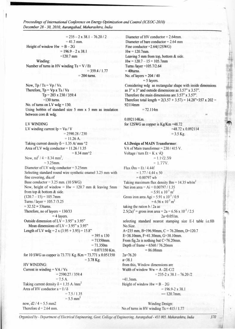
Proceedings of International Conference on Energy Optimization and Control (ICEOC-20l0)December 28 - 30,2010, Aurangabad, Maharashtra, lndia
= 235 - 2 x 38.1 - 76.20 / 2= 41.3 mm.
Height of window Hw = B - 2G= 196.9 - 2 x 38.1=120.7 mm
Winding:Number of turns in HV winding Ts = V / Et
= 359.4 11.77= 204 turns.
Now, Tp ITs = Vp I Vs.Therefore, Tp = Vp x Ts I Vs
Tp = 203 x 230 I 359.4=130 turns.
No. of turns on LV wdg = 130.Using bobbin of standard size 5 mm x 5 mm as insulationbetween core & wdg.
LVWrNDJNGLV winding current Ip = Va I V
= 2590.28 1230= 11.26 A.
Taking current density 6 = 1.35 AI mm "2Area of LV wdg conductor = 11.26 I 1.35
= 8.34 mm"2Now, 1td2I 4 = 8.34 rnm',
=3.25mm.Diameter of LV wdg conductor = 3.25mmSelecting standard round wire synthetic enamel 3.25 mm withfine covering, dia.ofBase conductor = 3.25 mm. (10 SWG)Now, height of window = Hw = 120.7 mm & leaving 5mmfrom top & bottom & side.(120.7 - 15) = 105.7mmTurns /layer = 105.7/3.25= 32.52 :::33turns.Therefore, no oflayers = 130/33
= 4layers.Outside dimension of LV = 3.95" x 3.95"
Mean dimensions of LV = 3.95" x 3.95"Length of LV wdg = 2 x (3.95 + 3.95) = 15.8"
=395x 130= 71350mm.= 71.350m= 0.071350 Km.
for 10 SWG as copper is 73.771 Kg /Km = 73.771 x 0.051350= 3.78 Kg.
HVWJNDJNG:Current in winding = VA I Vs
= 2590.27 I 359.4= 7.5 A.
Taking current density 0 = 1.35 A /mm'Area of HV conductor a = I 10
= 7.5 I 1.35= 5.5 mm2
now:d2 14 = 5.5 mm2Therefore d = 2.64 mm.
Diameter of HV conductor = 2.64mm.Diameter of bare conductor = 2.64 mmFine conductor =2.64(12SWG)Hw = 120.7mm.Leaving 5 mm from top, bottom & side.Hw = 120.7 - 15 = 105.7mmTurns /layer = I05.7/2.64=40tums.No. of layers = 204 140
= 5 layers.Considering wdg as rectangular shape with inside dimensionsas 3" x 3" and outside dimensions as 3.57" x 3.57".Therefore the main dimensions are 3.57" x 3.57".Therefore total length = 2(3.57 + 3.57) = 14.28"=357 x 202 =92114mm
=72.114m
0.092114Km.for 12SWG as copper is KgIKm =48.72
=48.72 x 0.092114= 3.5 Kg.
4.3.Design of MAIN Transformer:VA of Main transformer = 230 I 415 V.Voltage I turn Et = K x "Q
= 1.1"2.59= 1.77V.
Flux 0m = Et 14.44f= 1.77 I 4.44 x 50= 0.00797 wb
Taking maximum flux density Bm = 14.35 wb/m2
Net iron area = Ai = 0.00797 I 1.35= 5.91 x 10.3 m2
Gross iron area Agi = 5.91 x 10.3 10.9= 6.56 x 10.3 m2
taking the ration b I 2a as2.5(2a)2 = gross iron area = 2a = 6.56 x 10.3 I 2.5
2a=O.05Im.selecting standard nearest stamping size E-J table i.e.8BNo.Size.A=235 mm, B=196.90mm, C = 76.20mm, 0=120.7E=38.I Omm, F=4I.30mm, G=38.IOmm.From fig.2a is nothing but C=76.20mm.Depth of frame = 6560 176.20mm
= 86.08mm2a=76.20a==38.1from this, Window dimensions areWidth of window Ww = A -2E-C/2
= 235-2 x 38.1 - 76.20 /2=41.3mm.Height of window Hw = B - 2G
= 196.9-2 x 38.1= 120.7mm.
Winding Design:No.of turns in HV winding Ts = 415 I 1.77
Organisedby - Departmentof ElectricalEngineering.Govt.Collegeof Engineering.Aurangabad- 43/005. Maharashtra,India 370

Single Phase to Three Phase Converter Using Scoll Connection - A Practical Case Study
= 234 turns.No. of turns in LV winding Tp =234 x (230/415)
=130 turns.Using bobbin of standard size 3" x 3" as insulation betweencore of winding.LV winding current Jp =Va N
= 2590.28 1230=11.26 A.
Taking current density 6= 1.35 Almm2Area of LV wdg conductor = 11.26 11.35
=8.34mm2Now,nd2 14=8.34mm2
,
D=3.25rnrn.Diameter of LV wdg conductor = 3.25rnrn.Selecting standard round wire synthetic enamel 3.25 mm withfine covering,dia.ofBase conductor=3.25rnrn.(1 0 SWG)Now, height of window =Hw =120.7rnrn & leaving 5mm fromtop & bottom & side.(120.7 - 15) =105.7mmTurnsl layer = 105.7 13.25
=32.52 = 33 turns.Therefore, No.of layers = 130/33
=4 layers.Taking current density5= 1.35 Almm2Area of LV wdg conductor= 11.26/1.35
=8.34mm2
•
Now, nd2/4 = 8.34mm2,D=3.25mm.
Diameter of LV wdg conductor =3.25mmSelecting standard round wire synthetic enamel 3.25 mm withfineCovering, dia of base conductor =3.25mm. (I OSWG)Now, Height of window =120.7mm & leaving 5mm from top& bottom & side.(120.7 -15) =105.7rnrnTurns Ilayer=105.7 13.25
=32.52 =33turns.Therefore, No oflayers = 130.33
=4 layers.HVWindingCurrent in HV winding =VA 1Vs
=2590.27 1415= 6.24 =7.5A.
Taking current density 5 =1.35 AI mm'.Area of HV conductor a = I 15
=7.5/1.35=5.5mm2
Now, nd2 14 =5.5 mm"Therefore, d =2.64mm.Diameter of HV conductor =2.64mmDiameter of bare conductor =2.64mmFine conductor =2.64( 12SWG) Leaving 5mm from top,bottom & side.Hw= 120.7 -15=105.7mm.Turns /layer= I05.7/2.64
= 5.85=6 layers
4.4Design of CapacitorWe have,Rsc = 0.5 ohmXsc = 0.14 ohmNow for 0.8 lagging power factor,Load impedance referred to primary,Z=V II
=415/7.5= 55.33
Z = ~ (R2 + X2)Assume R I = 60 ohm
XI = 500hm.R Total = Rl + Rsc
= 60 + 0.5= 60.5 ohm
X Total = XI + Xsc= 50 + 1.23= 51.23 ohm
in order to have 90 phase difference the Xsc of capacitorshould beXsc = X total + R total (tan 53.7)
= 51.23 + 60.5(tan 53.7)= 133.59 ohm.
i.e. capacitor of value 23.82 microfaradThe KVAR of capacitor at full loadKVAR = (7.5)2 X 133.59
=7.5 KVAR
4.5 TestingTo calculate the regulation & efficiency we need to conductO.C, S.C test.The results of the same is as detailed below:O.C.TEST.Transformer Primary Primary Primary Secondary
Voltage (V) Current (A) Power(W) Voltage (V)Main (TI) 230 0.8 20 410Teaser (T2) 230 0.8 20 410
FORTIActual transformation ratio:V2 1V I = 230/410
= 0.56Now,Woc = Voc x loc x cos 00c20 = 410 x 0.8 x cos 00cCos 00c = 86.501m= losin0
= 0.8 x sin 86.50=0.79 Amp.
Iw= locos0= 0.8cos86.50= 0.0488 Amp
Woc at 4 I5 volt = 20(0.56)2
TestingTo calculate the regulation & efficiency we need to conductO.C, S.C test.The result of the same is as detailed below:
371

Proceedings of International Conference on Energy Optimization and Control (ICEOC-20 10)December 28 - 30,2010, Aurangabad, Maharashtra, India
O.C.TE3T. 1Transfonner Primary Primary Primary Secondary
Voltage (V) Current tAl Powcr(W) Voltage (V)Main (TI) 230 0.8 20 410Teaser (T2) 230 0.8 20 410
FORTIActual transformation ratio:V2 1VI = 230/410
= 0.56Now,Woc = Voc x loc x cos 00c20 = 410 x 0.8 x cos 00cCos 00c = 86.50Im = losin0
= 0.8 x sin 86.50= 0.79 Amp.
Iw= locos0= 0.8cos86.50=0.0488 Amp
Woc at 415 volt = 20(0.56)2
V. APPLICA TIO S AND SCOPEApplication:I. To give supply to an existing two phase system from a newthree phase source2. To supply two phase furnace from three phase source3. To supply three phase motors from a two phase source4. To interlink a two phase system with a three phase system.Example applications and scope for a three phaseconverter:a) Three phase converting in farmingPumps,compressors,irrigationsystems,airconditioning,refrigeration unit, convener, crane, hoist, grain mill.b) Three phase converting in large buildingsComputer installations, print rooms etc
VI. FUTURE PROSPECTSa) Polyphase supply: Because of high efficiency, transformersserve a excellent polyphase transformation devices inproviding higher polyphase systems.
A0---------,
8
Figure 14b)Balabce 3 phase contactor to the output supply,the 3 phasesupply from main can maintain the output constant.Because of this unbalancing,low voltage or single phasing ortwo phasing can be avoided.
-teaserR Y al r-~~m __ ]11§
i! - -1- ..
]llc•••• C":1
l f-'~3~
tt- I-J~~ rJ~JFigure 9
VII. OUTPUTWAVEFORMS OF OUTPUT VOLTAGES
WA VEFORMS OP OUTPUT' VOLTAOBS
J
ACKNOWLEDGME TBharati Vidyapeeth University College of Engineering, Pune-411043
REFERENCESI] ELECTRICAL TECHNOLOGY, B.L.THEREJA2] ELECTRICAL MECHINE DESIGN: A.KSA WNEY.3] THE J & p .ransformer book4] www.goog .•e.com5] Sales @ isomatic.co.uk6] Electrical Design: Estimation & costing by K.B.Raina S.K.Bhattacharya.
Organisedby - Department of Electrical Engineering. Govt. College of Engineering.Aurangabad - 43/ 005. Maharashtra, India 372