The Residences of Sherman Plaza Evanston, IL Residences of Sherman Plaza Evanston, IL Courtney...
33
The Residences of Sherman Plaza Evanston, IL Courtney Perrin Structural Option Adviser: Walt Schneider 10/31/2005 Structural Technical Report 2 Pro-Con Structural Study of Alternate Floor Systems Executive Summary Several alternate floor framing systems can be used in place of Sherman Plaza’s existing cast-in-place reinforced concrete system. This report evaluates and compares these floor systems in order to determine which could be considered for the final building redesign proposal. The systems analyzed in this report are: 1. Composite Steel System 2. Non-Composite Steel System 3. One-Way Pan Joist Concrete System 4. Hollow Core Plank System 5. Double Tee Beam System 6. Two-Way Concrete Slab System with Drop Panels 7. Concrete Waffle Slab System Preliminary sizes for slabs and framing members were determined using different design aids, such as RAM Structural System, the CRSI Handbook and the PCI Handbook. These seven systems were then compared and contrasted by several different criteria. The comparison took into account the system’s fire rating, susceptibility to vibration, weight, finish floor to ceiling section depth, constructability and cost. This criteria is not intended to be an exhaustive comparison but will be used to determine which systems should receive further investigation. When each of the systems was used in the typical bay in Sherman Plaza, each was found to have a number of positive and negative aspects. The steel systems were found to be the lightest and easiest systems to erect. The non- composite system is easier to erect than the composite system, because shear studs are
-
Upload
truongliem -
Category
Documents
-
view
219 -
download
2
Transcript of The Residences of Sherman Plaza Evanston, IL Residences of Sherman Plaza Evanston, IL Courtney...

The Residences of Sherman Plaza Evanston, IL
Courtney Perrin Structural Option Adviser: Walt Schneider 10/31/2005
Structural Technical Report 2 Pro-Con Structural Study of Alternate Floor Systems
Executive Summary
Several alternate floor framing systems can be used in place of Sherman Plaza’s existing cast-in-place reinforced concrete system. This report evaluates and compares these floor systems in order to determine which could be considered for the final building redesign proposal. The systems analyzed in this report are:
1. Composite Steel System 2. Non-Composite Steel System 3. One-Way Pan Joist Concrete System 4. Hollow Core Plank System 5. Double Tee Beam System 6. Two-Way Concrete Slab System with Drop Panels 7. Concrete Waffle Slab System
Preliminary sizes for slabs and framing members were determined using different design aids, such as RAM Structural System, the CRSI Handbook and the PCI Handbook. These seven systems were then compared and contrasted by several different criteria. The comparison took into account the system’s fire rating, susceptibility to vibration, weight, finish floor to ceiling section depth, constructability and cost. This criteria is not intended to be an exhaustive comparison but will be used to determine which systems should receive further investigation. When each of the systems was used in the typical bay in Sherman Plaza, each was found to have a number of positive and negative aspects. The steel systems were found to be the lightest and easiest systems to erect. The non-composite system is easier to erect than the composite system, because shear studs are

2
not needed. The disadvantages of the steel systems are that they have a large floor section depth and require additional fireproofing. The double tee and hollow core plank systems are both precast systems, which make them very easy to construct. They are also the least expensive systems. A major downfall, however, is that they have the largest floor section depths. The hollow core plank system has a very high weight, and the double tee system needs additional fireproofing and vibration could be an issue. The concrete waffle slab and one-way pan joist systems are both cast-in-place systems with relatively small ceiling to floor depths. These systems are harder to construct than the existing system however, since it is necessary to layout the pans to form the joists or waffle voids. Both these designs are more expensive. The waffle slab is even harder to design and therefore, the most expensive of the systems considered. The two-way flat slab with drop panels has the same section depth as the existing system. It requires no additional fireproofing, and vibrations will be low. It is somewhat harder to construct than the existing system, however, and its weight is higher. The purpose of the comparison of the floor framing systems is to determine which of the systems should be considered for further investigation. It was found that the steel systems, waffle slab, one-way pan joists, and two-way flat slab with drop panels should be continued as candidates for the building redesign. The double tee and hollow core plank systems, however, will not be considered due to their very large section depths, which can have a large impact on the costs and construction of the building.
3
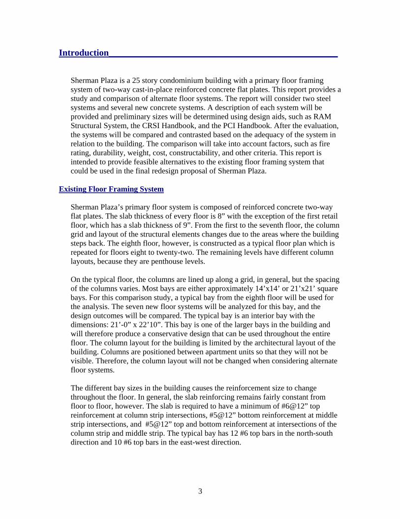
Introduction__________________________________________________
Sherman Plaza is a 25 story condominium building with a primary floor framing system of two-way cast-in-place reinforced concrete flat plates. This report provides a study and comparison of alternate floor systems. The report will consider two steel systems and several new concrete systems. A description of each system will be provided and preliminary sizes will be determined using design aids, such as RAM Structural System, the CRSI Handbook, and the PCI Handbook. After the evaluation, the systems will be compared and contrasted based on the adequacy of the system in relation to the building. The comparison will take into account factors, such as fire rating, durability, weight, cost, constructability, and other criteria. This report is intended to provide feasible alternatives to the existing floor framing system that could be used in the final redesign proposal of Sherman Plaza.
Existing Floor Framing System
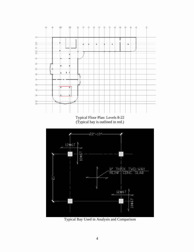
Sherman Plaza’s primary floor system is composed of reinforced concrete two-way flat plates. The slab thickness of every floor is 8” with the exception of the first retail floor, which has a slab thickness of 9”. From the first to the seventh floor, the column grid and layout of the structural elements changes due to the areas where the building steps back. The eighth floor, however, is constructed as a typical floor plan which is repeated for floors eight to twenty-two. The remaining levels have different column layouts, because they are penthouse levels. On the typical floor, the columns are lined up along a grid, in general, but the spacing of the columns varies. Most bays are either approximately 14’x14’ or 21’x21’ square bays. For this comparison study, a typical bay from the eighth floor will be used for the analysis. The seven new floor systems will be analyzed for this bay, and the design outcomes will be compared. The typical bay is an interior bay with the dimensions: 21’-0” x 22’10”. This bay is one of the larger bays in the building and will therefore produce a conservative design that can be used throughout the entire floor. The column layout for the building is limited by the architectural layout of the building. Columns are positioned between apartment units so that they will not be visible. Therefore, the column layout will not be changed when considering alternate floor systems. The different bay sizes in the building causes the reinforcement size to change throughout the floor. In general, the slab reinforcing remains fairly constant from floor to floor, however. The slab is required to have a minimum of #6@12” top reinforcement at column strip intersections, #5@12” bottom reinforcement at middle strip intersections, and #5@12” top and bottom reinforcement at intersections of the column strip and middle strip. The typical bay has 12 #6 top bars in the north-south direction and 10 #6 top bars in the east-west direction.
4
Typical Floor Plan: Levels 8-22 (Typical bay is outlined in red.)
Typical Bay Used in Analysis and Comparison
5
Floor Loads
The floor loading for Sherman Plaza follows the provisions of ASCE 7-98. Superimposed Dead Load:
• 15 psf, accounting for mechanical equipment, ceiling and floor finishes and other miscellaneous dead weight
Live Load: • 40 psf for residential areas • 20 psf extra for partitions • 100 psf for corridors, kitchens, dining rooms, stairways and
balconies • 80 psf approximated live load will be used as for the analysis of
the typical floor •
Total Superimposed Service Load = 95 psf Total Superimposed Factored Load = 146 psf Comparison Criteria
Each of the alternate floor systems and the existing system will be compared and contrasted by general criteria that will help to decide which system is ideal for the typical floor. The criteria considered in this report are:
1. Fire Rating 2. Weight of the System 3. Depth of the Structural Elements 4. Constructability of System 5. System Cost
Fire Rating The fire rating for Sherman Plaza has been determined by the BOCA National Fire Protection Code of 1996. The floor construction assembly should have a 2 hour fire rating. A 4.5” concrete slab achieves the 2 hour fire rating, which makes the existing 8” slab more than adequate. If an alternate system does not meet the fire rating, additional design is required to meet the rating, such as applying fireproofing or using a fire resistant material in the ceiling or floor assembly. Weight of the System The calculations of the weight of the system will take into account all beams, girders, slab and deck in the typical bay. The weight of the structural elements in the existing system is due to the 8” reinforced concrete slab. Therefore, the distributed load over the typical bay is 100 psf. This weight will be compared with the distributed loads of the alternate systems. The weight of the system is not the most important consideration due to the building’s foundation conditions, but it will still be taken into consideration in this report.
6
Depth of the Structural Elements Since Sherman Plaza is a twenty-five story building, any addition to the ceiling to floor finish depth will have a great impact on the building. An increase in the structural elements will either increase the overall building height or decrease the floor to ceiling height of the apartments. The increase in overall building height would produce much higher building costs for elements such as exterior cladding, stairwells, elevators and mechanical equipment. A significant decrease in floor to ceiling height would take away from the luxurious atmosphere created in the condominiums. The depth of the existing floor system is 8”, which leaves a large amount of space for mechanical ducts and floor and ceiling finishes. The 8” section depth will be compared with the depths of the other systems. Constructability and Cost Sherman Plaza is located in downtown Evanston, IL in a high traffic retail and residential area. It is therefore necessary that construction be finished in a reasonable amount of time. The speed of construction can be impacted by the time required to construct a floor assembly, the type of materials used, and the weight or amount of those materials. The existing flat plate system is relatively easy to construct and does not require any complex setup of forms. A precast system, however, would be easier to construct. The cost of the floor framing systems will also be taken into account.
Design Aids
The alternate floor framing systems will be designed using the following methods: • Composite Steel System: using the RAM Structural System to create a
model of the typical floor • Non-Composite Steel System: using output from the RAM Structural
System • One-Way Concrete Pan Joist System: using an estimate from the Concrete
Reinforcing Steel Institute (CRSI) Design Handbook, 9th Edition • Hollow Core Plank System: using the Precast/Prestressed Concrete
Institute (PCI) Design Handbook, 5th Edition • Double Tee Beam System: using an estimate from the PCI Design
Handbook • Two-Way Concrete Slab System with Drop Panels: using the CRSI
Design Handbook • Concrete Waffle Slab System: using the CRSI Design Handbook

7
Floor Framing Systems Evaluation _______________ Composite Steel System
RAM Structural System was used to design and analyze the composite steel floor system. The eighth floor of the building was modeled using the original column locations from the existing design. Girders and beams were added between the columns. For the typical bay, the infill beams are spaced at 7’-0” on center.
Eighth Floor Modeled in RAM Steel
For the composite design, a United Steel Deck, 22 gage, 2” Lok-Floor composite deck was chosen with 3” of concrete above the deck flutes, creating an overall concrete slab depth of 5”. The studs are 4” long and ¾” in diameter. This deck allows for a uniform superimposed service live load of 365 psf which is well over the actual service live load of 80 psf. The maximum span for a three span section of the deck is 8.19’ which is greater than the actual span, 7’-0”.

8
Typical Floor Design in Composite Steel
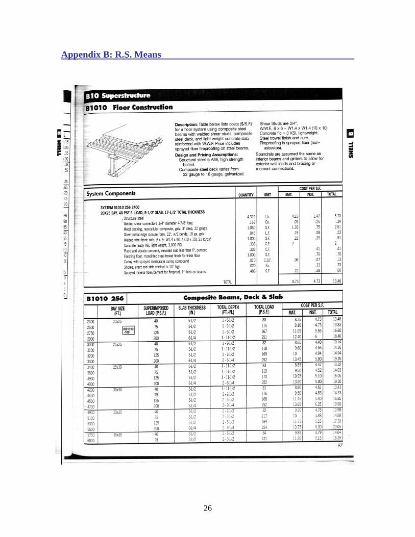
The beams for the typical bay, designed by RAM Steel, are W12x14 with 8 studs, and the girders are W14x22 with 30 studs. This design results in a load of 2962.67 lbs. from the beams, girders and studs, assuming the studs are approximately 10 lbs. each. This load, when distributed across the typical bay, is 6.179 psf. The deck and slab add another 38 psf, which sums to a total distributed load of 44.179 psf over the entire bay. This weight is significantly less than the weight of the existing system. The depth of the composite steel floor system will be equal to the depth of the girder plus the 5” slab. Therefore, the overall depth is 18.7”, which is much greater than the depth of the existing system. The composite steel system will add an extra 10.7” to each floor of the building. This system will also require additional fireproofing to achieve an adequate fire rating. The 3” of concrete slab above the deck flutes will produce a fire rating of an hour and a half. Additional fireproofing is needed on both the slab and the steel elements of the building. Cementitious fireproofing on the steel will produce a 3 hour fire rating, or the steel could be encased in a fire-resistant material ceiling assembly.

9
Non-Composite Steel System
The non-composite steel floor system was also designed using RAM Steel. The same floor design and spacing was used as in the composite design but the beams and girders are changed to non-composite. The deck was designed again using the United Steel Deck manual. The USD 22 gage 1.5” Lok-Floor was chosen with 2.5” concrete slab above the deck flutes, making an overall slab depth of 4”. Lightweight concrete was used again. This deck allows for a uniform superimposed service live load of 195 psf which is well over the actual service live load of 80 psf. The maximum span for a three span section of the deck is 7.06’ which is greater than the actual span, 7’-0”.
10
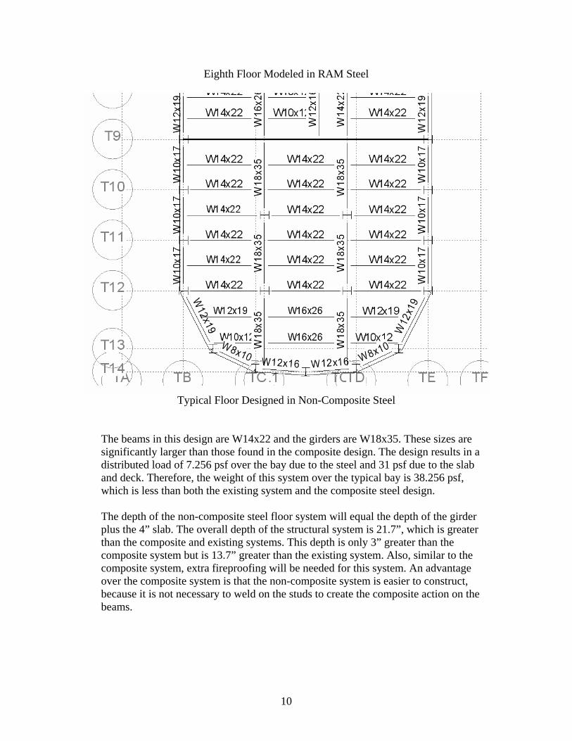
Eighth Floor Modeled in RAM Steel
Typical Floor Designed in Non-Composite Steel
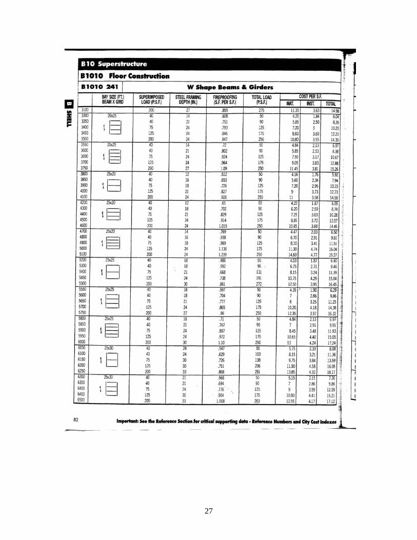
The beams in this design are W14x22 and the girders are W18x35. These sizes are significantly larger than those found in the composite design. The design results in a distributed load of 7.256 psf over the bay due to the steel and 31 psf due to the slab and deck. Therefore, the weight of this system over the typical bay is 38.256 psf, which is less than both the existing system and the composite steel design. The depth of the non-composite steel floor system will equal the depth of the girder plus the 4” slab. The overall depth of the structural system is 21.7”, which is greater than the composite and existing systems. This depth is only 3” greater than the composite system but is 13.7” greater than the existing system. Also, similar to the composite system, extra fireproofing will be needed for this system. An advantage over the composite system is that the non-composite system is easier to construct, because it is not necessary to weld on the studs to create the composite action on the beams.

11
One-Way Concrete Pan Joist System
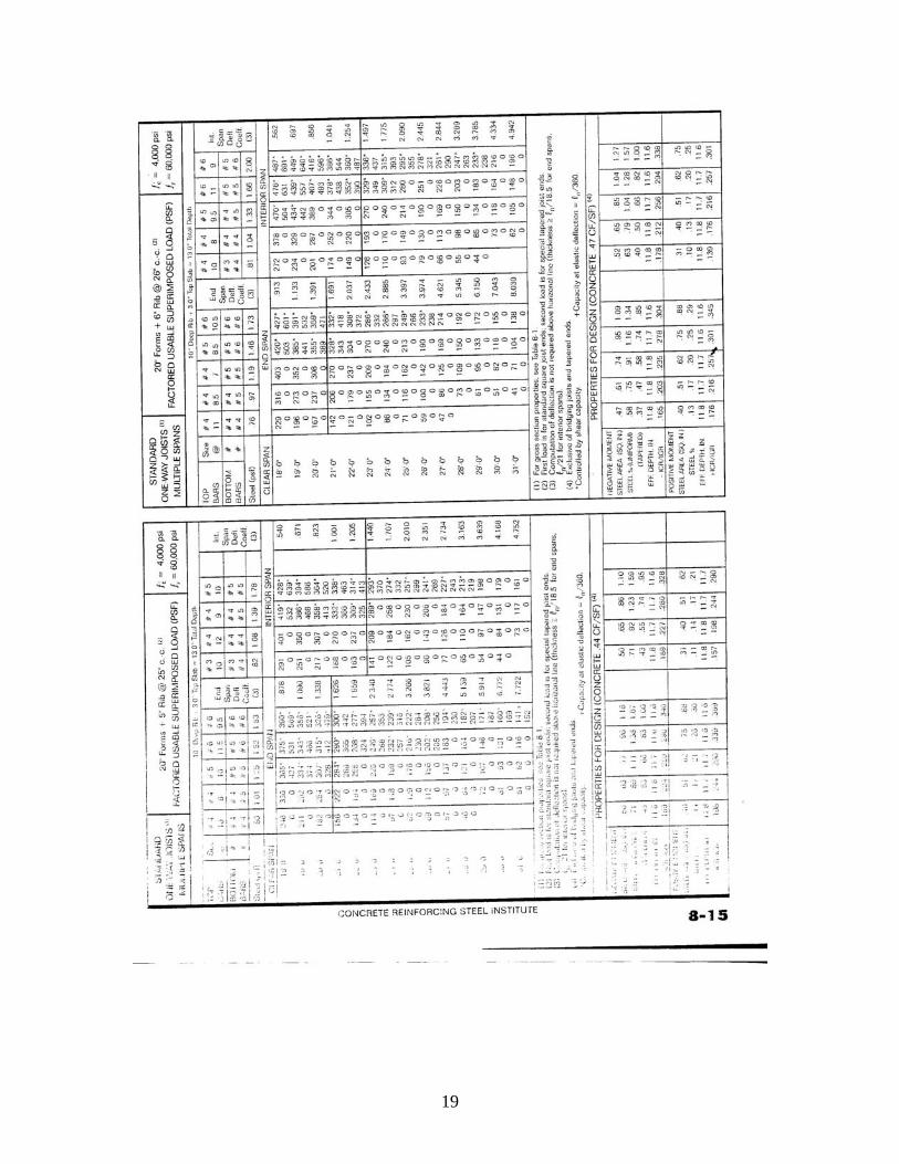
The one-way concrete pan joist system was designed using the Concrete Reinforcing Steel Institute (CRSI) Handbook. The system spans the 22’-10” direction, and two pan joist systems were considered. First, a system with 20” forms and 6” ribs was
considered. The span was approximated to be 23’, and the allowable factored load was 155 psf, which is greater than the maximum load of 146 psf. This system had a total depth of 13” and weighed 67 psf. The second system considered was a 30” form and 6” rib system. This system is also 13” in depth and weighs 61 psf. The capacity is 182 psf for a 23’-0” span. Since the second system is lighter and requires fewer pans, which therefore takes less time in construction, the second system is more
ideal than the first. The second system will be considered in the overall comparison of the floor systems. The pan joist system uses top bars of #5 spaced at 12” on center and bottom bars #5 and #6. This system has 10” deep ribs and a top slab of 3”. The 13” depth increases the floor to ceiling section by 5”. This 3” slab produces a fire rating of one a half hours. Therefore, additional fireproofing is necessary for this system to achieve the two hour rating. Time and constructability should also be taken into account when choosing this system. The setup for the pans takes much more time and makes construction harder than it would be for the flat plate existing system. Vibration could also be a concern with this system, because the slab is only 3” thick. The existing 8” slab will produce less vibration.
12
Hollow Core Plank System
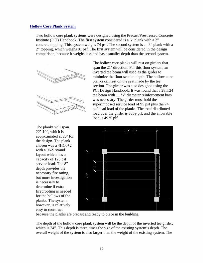
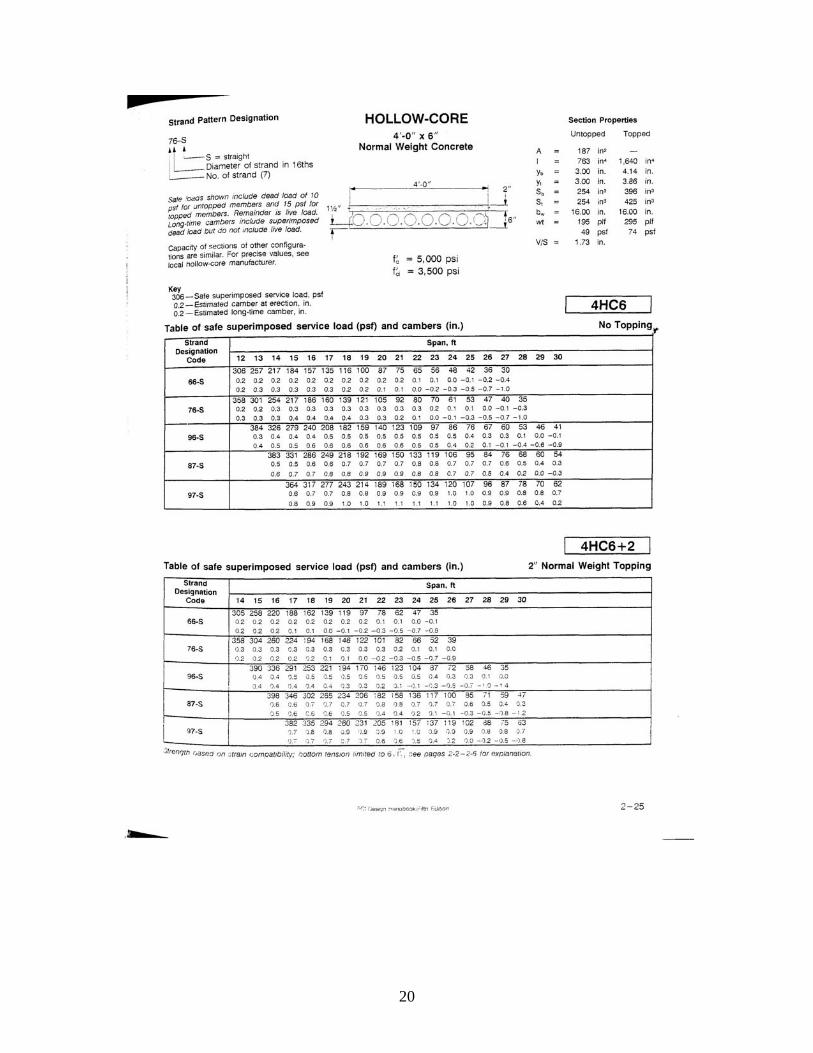
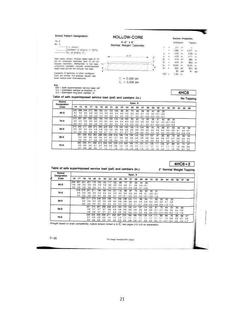
Two hollow core plank systems were designed using the Precast/Prestressed Concrete Institute (PCI) Handbook. The first system considered is a 6” plank with a 2” concrete topping. This system weighs 74 psf. The second system is an 8” plank with a 2” topping, which weighs 81 psf. The first system will be considered in the design comparison, because it weighs less and has a smaller depth than the second system.
The hollow core planks will rest on girders that span the 21’ direction. For this floor system, an inverted tee beam will used as the girder to minimize the floor section depth. The hollow core planks can rest on the seat made by the tee section. The girder was also designed using the PCI Design Handbook. It was found that a 28IT24 tee beam with 11 ½” diameter reinforcement bars was necessary. The girder must hold the superimposed service load of 95 psf plus the 74 psf dead load of the planks. The total distributed load over the girder is 3859 plf, and the allowable load is 4925 plf.
The planks will span 22’-10”, which is approximated at 23’ for the design. The plank chosen was a 4HC6+2 with a 96-S strand layout which has a capacity of 123 psf service load. The 8” depth provides the necessary fire rating, but more investigation is necessary to determine if extra fireproofing is needed for the hollows of the planks. The system, however, is relatively easy to construct because the planks are precast and ready to place in the building. The depth of the hollow core plank system will be the depth of the inverted tee girder, which is 24”. This depth is three times the size of the existing system’s depth. The overall weight of the system is also larger than the weight of the existing system. The
13
planks weigh 74 psf and the girders contribute an additional 43.8 psf. The total weight of the system is 117.8 psf.
Double Tee Beam System
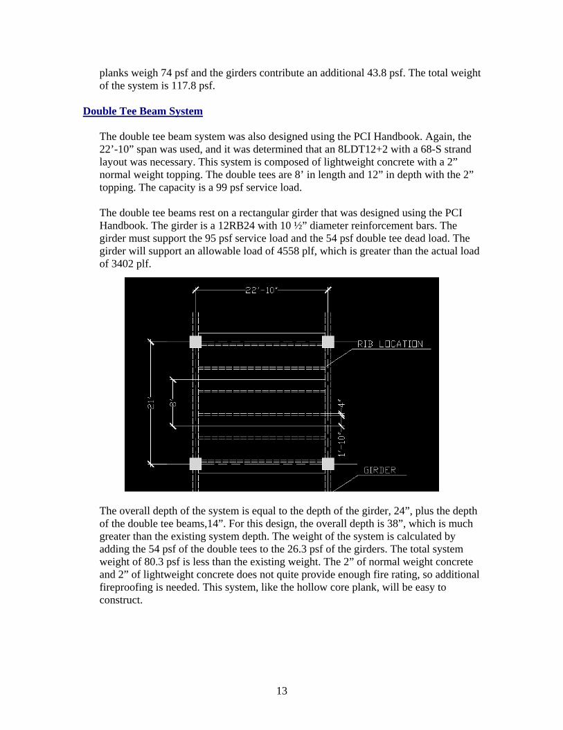
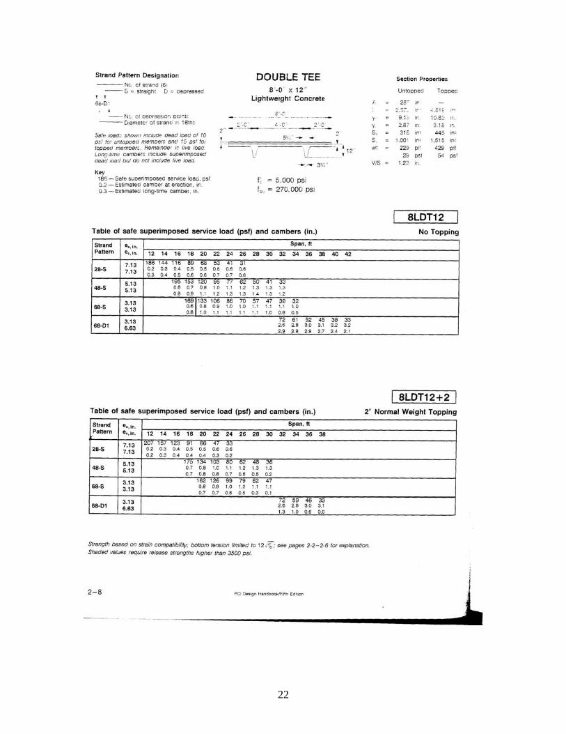
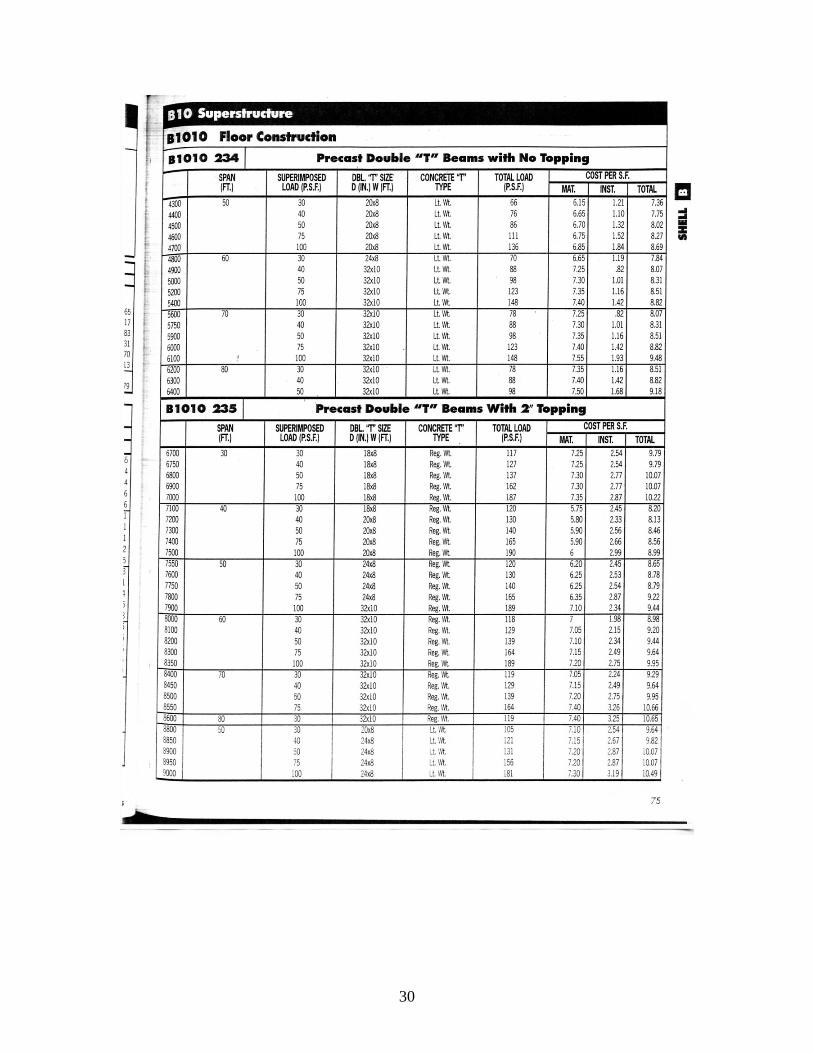
The double tee beam system was also designed using the PCI Handbook. Again, the 22’-10” span was used, and it was determined that an 8LDT12+2 with a 68-S strand layout was necessary. This system is composed of lightweight concrete with a 2” normal weight topping. The double tees are 8’ in length and 12” in depth with the 2” topping. The capacity is a 99 psf service load. The double tee beams rest on a rectangular girder that was designed using the PCI Handbook. The girder is a 12RB24 with 10 ½” diameter reinforcement bars. The girder must support the 95 psf service load and the 54 psf double tee dead load. The girder will support an allowable load of 4558 plf, which is greater than the actual load of 3402 plf.
The overall depth of the system is equal to the depth of the girder, 24”, plus the depth of the double tee beams,14”. For this design, the overall depth is 38”, which is much greater than the existing system depth. The weight of the system is calculated by adding the 54 psf of the double tees to the 26.3 psf of the girders. The total system weight of 80.3 psf is less than the existing weight. The 2” of normal weight concrete and 2” of lightweight concrete does not quite provide enough fire rating, so additional fireproofing is needed. This system, like the hollow core plank, will be easy to construct.

14
Two-Way Flat Slab with Drop Panels System
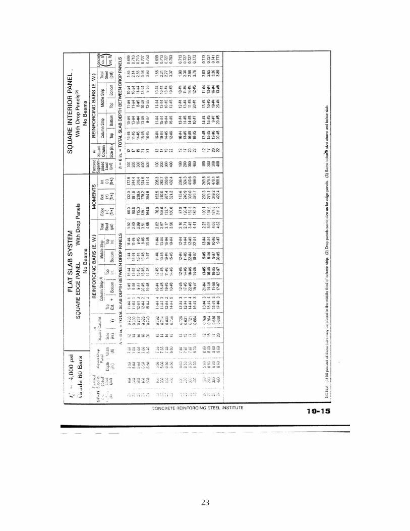
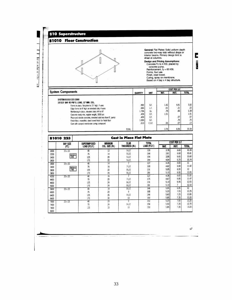
The two-way flat slab system with drop panels was designed with the CRSI Handbook. The bay was designed for the longer span of 22’-10”. It was determined that a square drop panel of 6.5” depth and 7.67’ width was necessary. For the column strip, 13 #5 bars on top and 11 #5 bars on bottom are needed. The middle strip receives 13 #4 bars on top and 11 #4 bars on bottom. The capacity of this system is 200 psf superimposed factored load. This design is overly conservative because the CRSI Handbook designs the flat slab in increments of 100 psf. Less reinforcement would probably be needed if the slab were designed for the 146 psf factored load.
The total slab depth between drop panels is 8” which is equal to the existing system. The drop panels add 6.5”, but for this system, mechanical equipment can be run through the middle section of the slab where the drop panels won’t interfere. Therefore, the depth of this system can be taken as 8”. The additional drop panels do increase the weight of the system to greater than the existing system. The total steel in the system weighs 2.36 psf, and
the total weight is 112.33 psf. The drop panels also provide an extra difficulty in the construction of the system. The 8” slab provides more than enough fire protection. The flat slab with drop panels also provides a great resistance to vibrations.

15
Concrete Waffle Slab System
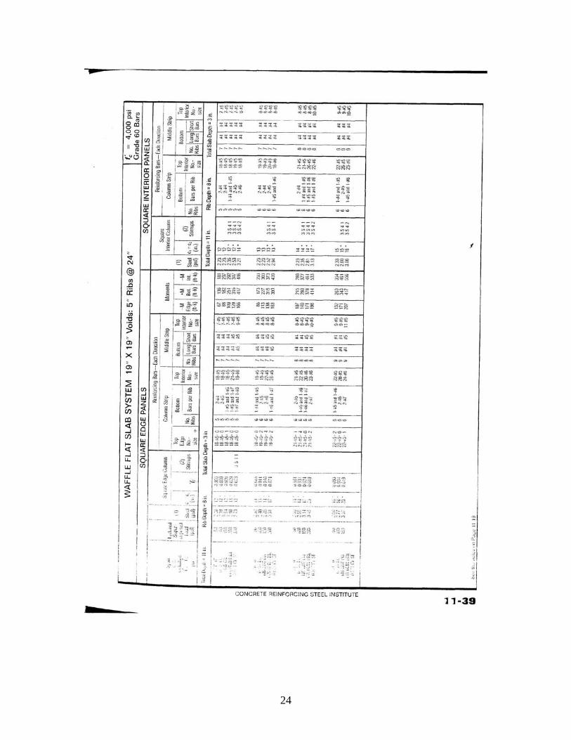
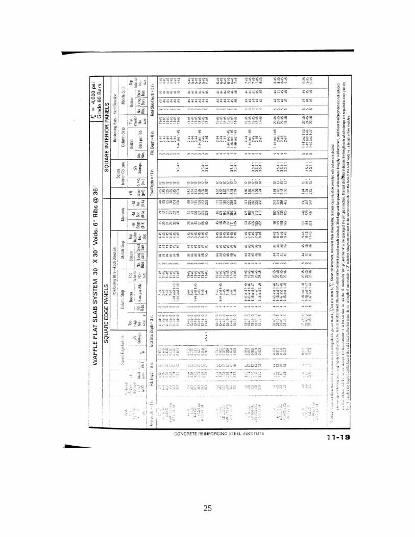
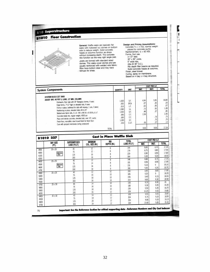
The CRSI Handbook was used to design the concrete waffle slab system. After consideration of two systems with different void lengths, the 30”x30” void system was chosen. The ribs between voids are 6”, and the rib depth is 8”. There is a 3” slab on top, making a total depth of 11”. Since the typical bay is not completely square, it was necessary to approximate the dimensions as 24’-0”x24’-0”. This will produce a more conservative design. The factored superimposed allowable load is 150 psf. The system was designed to have 2 #5 bars in the bottom of the rib in the
column strip and 18 #5 bars in the top. The middle strip needs #4 longs bars in the bottom and 7 #5 bars in the top. This reinforcement produces a steel weight of 2.05 psf which is added to the 71 psf of the waffle slab for a total weight of 73.05 psf. This system would be one of the most hard to construct and will take a long amount of time to layout the pans to create the waffle. In addition, extra fireproofing is needed for the 3” slab depth.
16
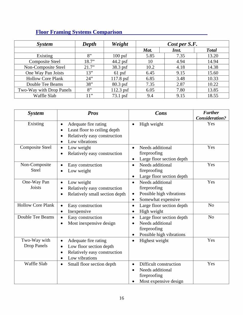
Floor Framing Systems Comparison System Depth Weight Cost per S.F.
Mat. Inst. Total Existing 8” 100 psf 5.85 7.35 13.20
Composite Steel 18.7” 44.2 psf 10 4.94 14.94 Non-Composite Steel 21.7” 38.3 psf 10.2 4.18 14.38 One Way Pan Joists 13” 61 psf 6.45 9.15 15.60 Hollow Core Plank 24” 117.8 psf 6.85 3.48 10.33 Double Tee Beams 38” 80.3 psf 7.35 2.87 10.22
Two-Way with Drop Panels 8” 112.3 psf 6.05 7.80 13.85 Waffle Slab 11” 73.1 psf 9.4 9.15 18.55
System Pros Cons Further Consideration?
Existing • Adequate fire rating • Least floor to ceiling depth • Relatively easy construction • Low vibrations
• High weight Yes
Composite Steel • Low weight • Relatively easy construction
• Needs additional fireproofing
• Large floor section depth
Yes
Non-Composite Steel
• Easy construction • Low weight
• Needs additional fireproofing
• Large floor section depth
Yes
One-Way Pan Joists
• Low weight • Relatively easy construction • Relatively small section depth
• Needs additional fireproofing
• Possible high vibrations • Somewhat expensive
Yes
Hollow Core Plank • Easy construction • Inexpensive
• Large floor section depth • High weight
No
Double Tee Beams • Easy construction • Most inexpensive design
• Large floor section depth • Needs additional
fireproofing • Possible high vibrations
No
Two-Way with Drop Panels
• Adequate fire rating • Low floor section depth • Relatively easy construction • Low vibrations
• Highest weight Yes
Waffle Slab • Small floor section depth • Difficult construction • Needs additional
fireproofing • Most expensive design
Yes
17
Conclusion
Several alternate floor framing systems were considered as an alternative to the existing two-way cast-in-place reinforced concrete flat plate system of Sherman Plaza. The seven systems that were analyzed in this report were:
1. Composite Steel System 2. Non-Composite Steel System 3. One-Way Pan Joist Concrete System 4. Hollow Core Plank System 5. Double Tee Beam System 6. Two-Way Concrete Slab System with Drop Panels 7. Concrete Waffle Slab System
Each of the systems were found to work for the typical bay, but the systems had positive and negative aspects that make them a good choice or not for this building. The steel systems were found to be the lightest and easiest systems to erect. The non-composite system is easier to erect than the composite system, because shear studs are not needed. The disadvantages of the steel systems are that they have a large floor section depth and require additional fireproofing. Both of these systems could use further investigation to determine if they could be used in the building redesign. The double tee and hollow core plank systems are both precast systems, which make them very easy to construct. They are also the least expensive systems. A major downfall, however, is that they have the largest floor section depths. The hollow core plank system has a very high weight, and the double tee system needs additional fireproofing and vibration could be an issue. Since the floor section of these systems is three times or more the depth of the existing system, they will not be considered for further investigation. The increased depth can have a major impact on the building. The concrete waffle slab and one-way pan joist systems are both cast-in-place systems with relatively small ceiling to floor depths. These systems are harder to construct than the existing system however, since it is necessary to layout the pans to form the joists or waffle voids. Both these designs are more expensive. The waffle slab is even harder to design and therefore, the most expensive of the systems considered. Despite the high costs, however, both these systems will be continued as candidates in the building redesign. The two-way flat slab with drop panels has the same section depth as the existing system. It requires no additional fireproofing, and vibrations will be low. It is somewhat harder to construct than the existing system, however, and its weight is higher. It will also be considered for further investigation.

18
Appendix A: CRSI and PCI Design Handbooks
19
20
21
22
23
24
25
26
Appendix B: R.S. Means
27

28

29
30

31
32
33