The purpose of this Pavement Management Program ... - TN.gov · While loading and traffic have...
94
STANDARD OPERATING GUIDELINES May 2013 PAVEMENT MANAGEMENT PROGRAM
Transcript of The purpose of this Pavement Management Program ... - TN.gov · While loading and traffic have...

STANDARD OPERATING GUIDELINES
May 2013
PAVEMENT
MANAGEMENT
PROGRAM


Page 1 of 93
I. Contents INTRODUCTION .................................................................................................................................................... 2
PAVEMENT PRESERVATION ................................................................................................................................. 5
SYSTEM METRICS ................................................................................................................................................. 7
TREATMENT LIFE EXTENSION ............................................................................................................................... 9
NETWORK HEALTH ............................................................................................................................................... 9
OPTIMIZATION ................................................................................................................................................... 10
PROJECT IDENTIFICATION AND SELECTION ........................................................................................................ 13
CRACK SEALING TREATMENT ............................................................................................................................. 28
FOG SEAL ............................................................................................................................................................ 30
LONGITUDINAL JOINT STABILIZATION ............................................................................................................... 31
SLURRY SEAL ....................................................................................................................................................... 32
MICROSURFACE.................................................................................................................................................. 34
SCRUB SEAL ........................................................................................................................................................ 36
CRS2P CHIP SEAL WITH A FOG SEAL ................................................................................................................... 39
THIN OVERLAY TREATMENT ............................................................................................................................... 42
CHIP SEAL WITH THIN HOT MIX OVERLAY.......................................................................................................... 45
CAPE SEAL........................................................................................................................................................... 48
MILL AND REPLACE TREATMENT ........................................................................................................................ 51
UNDER-DRAIN OUTLET CLEANING AND REPAIR ................................................................................................ 53
TDOT BICYCLE & PEDESTRIAN POLICY (RESURFACING) ...................................................................................... 58
ADA RAMP IMPROVEMENTS .............................................................................................................................. 60
ENVIRONMENTAL DOCUMENTS AND PERMITS ................................................................................................. 62
FUNDING ........................................................................................................................................................... 69
LOW COST SAFETY IMPROVEMENTS / HSIP FUNDING ...................................................................................... 72
RAILROAD INVOLVEMENT .................................................................................................................................. 85
Page 2 of 93
INTRODUCTION Tennessee continues to have one of the top road systems in the nation. TDOT has received eight national awards for perpetual pavements from the National Asphalt Pavement Alliance. Media publications and reports have rated Tennessee’s network as one of the best in the nation. National research projects have shown TDOT has the smoothest Interstates in the nation. Our infrastructure has proved to be well built and able to stand the test of time and the repetitive loading that moves our nation’s economy. However, many challenges face Tennessee in the future. TDOT’s purchasing power is eroding. For several years, construction materials have increased at a higher rate than the Consumer Price Index. Gas and diesel tax revenues are flat or trend downward as total vehicle miles traveled decline. Most importantly, the cost of oil has risen tremendously. A barrel of crude oil stayed between $20 and $30 from 1987 to 2004 (see chart below). Since 2004, oil has continued to climb as high as $135 per barrel.
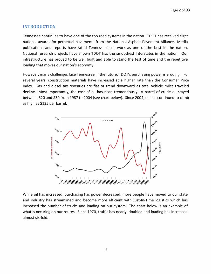
While oil has increased, purchasing has power decreased, more people have moved to our state and industry has streamlined and become more efficient with Just-In-Time logistics which has increased the number of trucks and loading on our system. The chart below is an example of what is occuring on our routes. Since 1970, traffic has nearly doubled and loading has increased almost six-fold.
2
Page 3 of 93
3

Page 4 of 93
While loading and traffic have increased and purchasing power has worn away, Tennessee’s resurfacing program budget has remained the same for many years. However, since 2008, the Department has been more closely reviewing metrics. The Department found that the number of lane miles resurfaced annually has been trending downward. In addition, in the 1980’s and 1990’s most projects had both leveling and surface mix (see chart below).TDOT must pave on State Routes 2,630 lane-miles each year. In the late 2000’s, TDOT averaged 2,043 lane-miles, which is a 15.4 year cycle. Since 2007, the Interstate resurfacing program has averaged 472 lane miles of paving each year (10.9 year cycle over the last 5 years.
4

Page 5 of 93
With all of the challenges TDOT faces in the future, it has become clear that the Department cannot continue down the path it is going without adding more money to our resurfacing program, allowing acceptable level of service to be lowered, or by adding a variety of cost effective treatments to take care of our network. In 2008, TDOT performed a customer satisfaction survey on our Department and the care of our assets. This survey polled the entire state and covered everything from striping, mowing cycles, and condition of our pavements. The motoring public made it clear that they were satisfied with the condition of our network in 2008. The Department decided to manage our assets to maintain this baseline level of service. Although Pavement Conditions was identified as the top priority by the highway users, this benefit of improved pavement condition is connected to many secondary benefits. For example, improved pavement condition will also translate to safer roads, fewer repairs, less delay, more efficient roadway operations, and better performance for a longer period of time. Another benefit of improved pavement condition is the lower overall costs for pavement preservation. Not only the Department but the public is concerned about costs. Taxpayers want to get the best system of roads possible for their investment. They would like to know that their funds are being spent wisely.
PAVEMENT PRESERVATION Pavements deteriorate as a result of a combination of several factors. The primary mechanisms of asphalt pavement deterioration are caused by environmental forces such as aging and oxidation, and load-related forces. Load-related forces result in the development of structural distresses such as fatigue cracking and rutting; environmental forces, which include the effects of temperature, oxidation, and exposure to sunlight, result in distresses such as thermal cracking, block cracking, and weathering and raveling. As the pavement cracks it loses its load-carrying capacity and becomes even more susceptible to the effects of moisture infiltration to subsurface layers, which can then weaken and further deteriorate. Portland Cement Concrete (PCC) pavements also deteriorate in response to both environmental and load-related forces. Loads create stresses at slab joints, edges, and cracks which may, ovetime, cause these discontinuities to break down. Environmental forces include freeze-thaw actions and changes in moisture content and temperature. The environmental forces can contribute to cracking, joint-associated deterioration, and roughness. Loads and environmental effects combine over time to cause most pavements to fail. Construction and material problems compound these effects and further contribute to pavement deterioration. The proper maintenance of our roadway pavement plays an integral part in

Page 6 of 93
retarding pavement deterioration. It is important to realize that no pavement lasts forever, and pavement preservation activities do not prevent a pavement from eventually deteriorating. They are intended to reduce the rate of deterioration and to make highway maintenance more cost-effective.
The maintenance and repair of pavement consists of three (3) types of maintenance. These are: (1) routine, (2) reactive, and (3) proactive or preventive. Routine maintenance is the day-to-day pavement maintenance activities that are scheduled or whose timing is within the control of maintenance personnel. Reactive maintenance occurs when the pavement section is allowed to deteriorate to a fair to poor condition in terms of both ride quality and structural condition. At this point, structural damage has occurred, and the objective of rehabilitative treatment is to repair that damage and restore the pavement. Thus, the approach is reactive and can be a costly and time-consuming process. A proactive or preventive maintenance approach entails the application of a series of low-cost, preventive maintenance treatments that individually last for a few years.
Preventive maintenance is the planned strategy of cost-effective pavement treatments to an existing roadway to extend the life or
improve the serviceability of the pavement. The purpose of this Pavement Management Program is to protect the pavement structural integrity, maintain functional characteristics, slow the rate of pavement deterioration and/or correct pavement surface deficiencies. The method of obtaining this will begin with preventive maintenance activities. Emphasis will be placed on both rigid and flexible pavement. A high priority will be given to newly constructed or resurfaced pavement structures. Appropriate preventive maintenance activities should be employed until repair costs exceed the benefits derived from such activities or until the pavement structure needs to be rehabilitated or reconstructed.

Page 7 of 93
SYSTEM METRICS Instead of looking solely at the number of miles paved each year, the Department also is now looking at our Pavement Management System data to measure the health of our network and forecast possible future needs. Pavement Management data is useful in project selection, but is also very useful in measuring both the health and change in the network over time. Tennessee collects Pavement Management data for Interstates every year and for State Routes every other year. Measuring the Pavement Quality Index (PQI) change by state/region/county over at least two cycles will show both system health and possible areas to allocate future resurfacing dollars. The Department is also using a fairly new asset management concept called Remaining Service Life (RSL) to measure and justify dollars spent on the resurfacing program. This concept may be used for forecasting future needs.
“The measurable loss of pavement life can be thought of as the network’s total lane-miles multiplied by 1 year, that is, lane-mile-years...…To offset this amount of deterioration over the entire network, the agency would need to annually perform a quantity of work equal to the total number of lane-mile-years lost just to maintain the status quo. Performing a quantity of work that produces fewer than the lane-mile- years required would lessen the natural decline of the network, but still fall short of maintaining the status quo. ……When evaluating pavement preservation treatments in this analysis, it is appropriate to think in terms of “extended life” rather than design life. The term design life…relates better to the new pavement’s structural adequacy to handle repetitive loadings and environmental factors. This is not the goal of pavement preservation. Each type of treatment has unique benefits that should be targeted to the specific mode of pavement deterioration. This means that life extension depends on factors such as type and severity of distress, traffic volume, environment and so forth.”
Tennessee’s highway network consists of 5,151 lane miles of Interstate and 31,555 lane miles of State Routes. Each year, TDOT must create a work program to add lane mile years equivalent to the total number of lane miles in the system. By doing this, Tennessee’s roads will be maintained at their current level of service and the system will not decline.
1 “A Quick Check of Your Highway Network Health”, Larry Galehouse and Jim Sorenson, Publication No. FHWA-IF-07-006

Page 8 of 93
Year Interstate (Lane Mile
Years Actual)
Interstate (Lane Mile
Years Needed)
State Route (Lane Mile
Years Actual)
State Route (Lane Mile
Years Needed) Total Actual Total
Needed
2009 7,930
5,058
21,236
31,641
29,166
36,736
2010 6,140
5,058
15,775
31,641
21,915
36,736
2011 6,719
5,058
21,168
31,641
27,887
36,736
2012 4,747
5,058
22,291
31,641
27,038
36,736
2013 5,363
5,058
24,149
31,641
29,513
36,736
Statewide
-
5,000
10,000
15,000
20,000
25,000
30,000
35,000
40,000
2009 2010 2011 2012 2013
Total Actual
Total Needed
State Routes Interstates
Page 9 of 93
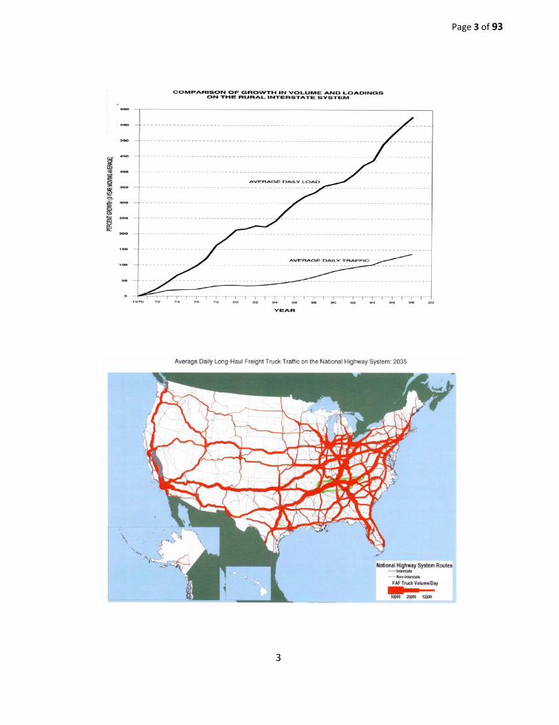
TREATMENT LIFE EXTENSION When calculating lane-mile-years for optimizing yearly work plans, life extension must be assumed for each treatment used and then multiplied by the total lane miles of the project. Below is a table with an assumed life extension for each type of treatment. These life extensions are based on past experience and were included in a 2008 memo to FHWA as a request to activities used in asset management that are eligible for funding with federal dollars.
Treatment Type Life Extension 411 D 12
Mill 411D 12 Thin Lift D 10
Thin Lift 7 Microsurfacing (22 lbs/SY) 7 Microsurfacing (32 lbs/SY) 8
Chip Seals 6 Chip Seal with Thin Lift
Overlay 12
Cape Seal 10 Crack Sealing 2
Longitudinal Joint Stabilization 3
Example: Macon County State Route 262 has a Paving Project with 411 D. The project starts at Log Mile 0.00 and ends at Log Mile 7.00.
Required: Calculate Lane-Mile-Years for this project
Solution: This is a 2-lane Route. Since the project is 7.0 miles along, multiply 7.0 x 2 =
14.0 Lane Miles. Then, multiply the 14.0 Lane Miles x 12 year life extension from the table above.
14.0 Lane Miles x 12.0 Years = 168.0 Lane-Mile-Years
NETWORK HEALTH Pavement Management System data can be a tool used in two possible fashions. The first is for selecting or confirming projects for next year’s work program. Each route candidate would have its data looked at individually to select or confirm the optimized treatment. Later in this Manual there is a large section detailing treatments and data thresholds. The second means for using Pavement Management System data is to measure and weigh the health of the Department’s network by comparing Average Pavement Quality Index data for county or region over time to see the relative improvements and decline.

Page 10 of 93
The data below will show trends of Average PQI by county since 2003. Green represents higher (or better) data and red represent the lower (or worse) numbers in comparison with all of the counties in the region considered. Please also note that the 2011 data has dropped on average 0.20 due to TDOT amending the current PMS Contract to include downward imaging to measure distress.
Average PQI County CL Miles State Routes 2003 2005 2007 2009 2011
Bedford 159.25 Cheatham 98.27 Davidson 276.16 Dickson 159.96
Giles 153.49 Hickman 119.18 Houston 62.53
Humphreys 78.74 Lawrence 149.77
Lewis 69.78 Lincoln 180.77
4.36 4.03 4.16 4.20 4.04 4.30 4.24 4.21 4.27 4.00 4.12 4.02 3.90 4.00 3.56 4.43 4.43 3.80 4.31 3.91 4.44 4.27 4.22 4.22 3.92 4.52 4.11 4.27 4.35 4.02 4.22 4.40 4.27 4.25 3.51 4.56 4.19 4.32 4.44 4.01 4.39 4.23 4.37 4.21 4.11 4.47 4.21 4.32 4.23 3.93 4.23 4.33 4.26 4.27 4.02
When planning the work program for next year, it is very important to look at the health of the regional network. This process will reveal to the Resurfacing Coordinator counties that may need more work or less work. It is a tool for allocating funds to manage assets.
OPTIMIZATION In the past, the Department treated all four Regions equally and allocated an equal amount of funds for the resurfacing program. Over time some regions flourished and some suffered in network health due to the fact that there are varying amount of assets in each region. Now the funds are allocated based on percentage of lane miles in each region. Going forward it is important for each region to look at each district individually based on percentage of lane miles as well. It is also important to consider network health in each county and district to allocate funds for projects. The Department has the great challenge ahead of caring for a multi-billion dollar investment at the lowest possible cost. It is not TDOT's goal or mission to divide the work equally among contractors or take a worst/first approach to pavement management, but rather to administer a program that provides the citizens of Tennessee with the best roads at the lowest possible cost.

Page 11 of 93

Page 12 of 93

Page 13 of 93
Pavement Management Program – Project Identification and Selection
TDOT’s pavement management program contains treatments of preventive maintenance, minor rehabilitation, and major rehabilitation. Possible resurfacing projects will be identified with data from the Pavement Management System (PMS) and the regional roadway history. The priority of this identification is age and the overall Pavement Quality Index (PQI). As part of the Pavement Management Program, the regional resurfacing coordinator main- tains a history of the region’s roadways. The history includes all resurfacing roadway sections and the last year each was addressed, and is provided to the regional assistant chief engineer, the Regional director of operations, and the Resurfacing Coordinator.. Each district Maintenance superintendent is given a copy of the resurfacing history for their district. Each region is given Pavement Management System data for State Routes every other year. The roadway history is used to determine past project resurfacing limits, Log Mile to Log Mile. This data plus visual inspection by regional staff determine a large list of potential projects for next season’s work. Once a potential projects list is developed for each district, a team from the region will visit these projects to confirm PMS data, evaluate with visual inspection, and decide potential treatments. They will also evaluate any possible safety-feature upgrades using the Low-Cost Safety Improvement Checklist. Prior to the team’s district tour, a meeting will be held with the district staff to discuss budget for that particular area based on lane-miles, lane-mile-years goals, and percentage of work required for this area. Each region shall allocate their dollars according to the following:
• 75% Traditional hot mix asphalt • 25% Alternative Treatments (with minimum 10% Microsurfacing)
The project selection process continues with a visual inspection of those projects initially identified. Priority will be given to sections that will not last another year without falling from the minor rehabilitation group or preventive maintenance group. These projects are inspected to determine the best-possible treatment. Visual inspection also checks to see if some type of routine maintenance in an area might remove the project from its border-line condition. After the border-line projects are addressed, remaining projects are inspected to determine the optimum treatment for each project. The team then estimates if the project is not addressed this year, will the same fix be acceptable the following Year. If not, the project is classified as second priority.
Page 14 of 93
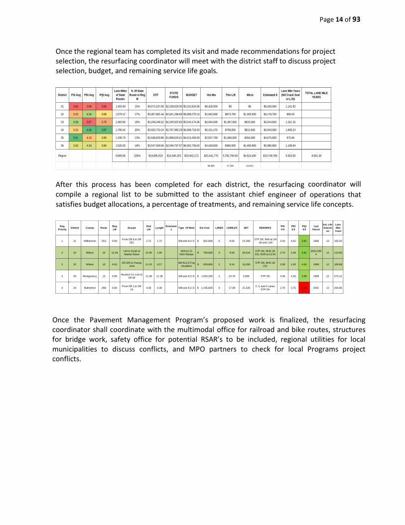
Once the regional team has completed its visit and made recommendations for project selection, the resurfacing coordinator will meet with the district staff to discuss project selection, budget, and remaining service life goals.
After this process has been completed for each district, the resurfacing coordinator will compile a regional list to be submitted to the assistant chief engineer of operations that satisfies budget allocations, a percentage of treatments, and remaining service life concepts.
Once the Pavement Management Program’s proposed work is finalized, the resurfacing coordinator shall coordinate with the multimodal office for railroad and bike routes, structures for bridge work, safety office for potential RSAR’s to be included, regional utilities for local municipalities to discuss conflicts, and MPO partners to check for local Programs project conflicts.
District PSI Avg PDI Avg PQI AvgLane Miles
of State Routes
% Of State Route in Reg
IIISTP STATE
FUNDS BUDGET Hot Mix Thin Lift Micro Estimated $ Lane Mile Years (NO Crack Seal
or LJS)
TOTAL LANE MILE YEARS
31 3.05 3.99 3.66 1,403.40 15% $3,073,187.06 $2,169,629.00 $5,242,816.06 $6,426,000 $0 $0 $6,426,000 1,141.92
32 3.20 4.24 3.88 1,579.12 17% $3,457,981.44 $2,441,288.69 $5,899,270.13 $1,942,000 $973,700 $1,263,000 $4,178,700 885.04
33 3.39 3.97 3.78 1,483.80 16% $3,249,248.22 $2,293,925.83 $5,543,174.06 $2,944,600 $1,967,000 $633,000 $5,544,600 1,101.32
34 3.24 4.34 3.97 1,790.44 20% $3,920,733.24 $2,767,985.29 $6,688,718.53 $5,331,470 $798,000 $813,600 $6,943,080 1,606.24
35 3.51 4.10 3.90 1,208.70 13% $2,646,829.98 $1,868,626.61 $4,515,456.59 $2,637,700 $1,684,000 $354,000 $4,675,600 975.84
36 3.32 4.19 3.90 1,620.20 18% $3,547,939.06 $2,504,797.57 $6,052,736.63 $4,160,000 $360,000 $1,460,800 $5,980,800 1,199.64
Region 9,085.66 100% $19,895,919 $14,046,253 $33,942,172 $23,441,770 5,782,700.00 $4,524,400 $33,748,780 6,910.00 8,561.46
69.46% 17.13% 13.41%
RegPriority District County Route Beg
LM Descpt EndLM Length Exclusion
s Type Of Work Est Cost LANES LNMILES ADT REMARKS PSI0-5
PDI0-5
PQI0-5
Last Paved
Est. Life Extensi
on
Lane Mile
Years
1 31 Williamson 253 0.00 From SR 6 to SR 252 1.72 1.72 Mill and 411 D $ 602,000 5 8.60 15,300 STP OK; RxR at LM
.50 and 1.60 2.44 4.62 3.82 1996 12 103.20
2 32 Wilson 10 12.46 I-40 to South of Market Street 14.36 1.90 Mill 411 D
ADA Ramps $ 760,000 5 9.50 20,410 STP OK; NHS US 231; RXR at 13.94 2.76 4.39 3.82 2001/199
4 12 114.00
2 32 Wilson 10 6.63 SR 265 to Paving Joint 11.20 4.57 Mill 411 D Fog
shoulders $ 639,800 2 9.14 10,450 STP OK; NHS US 231 3.58 4.26 4.04 1999 12 109.68
3 33 Montgomery 13 0.00 Houston Co Line to SR 48 11.38 11.38 Mill and 411 D $ 1,593,200 2 22.76 3,990 STP OK 3.46 4.25 3.99 1999 12 273.12
4 34 Rutherford 268 0.00 From SR 1 to SR 10 4.30 4.30 Mill and 411 D $ 1,195,600 0 17.08 21,320 2, 3, and 4 Lanes;
STP OK 2.70 3.75 3.39 2002 12 204.96
Page 15 of 93
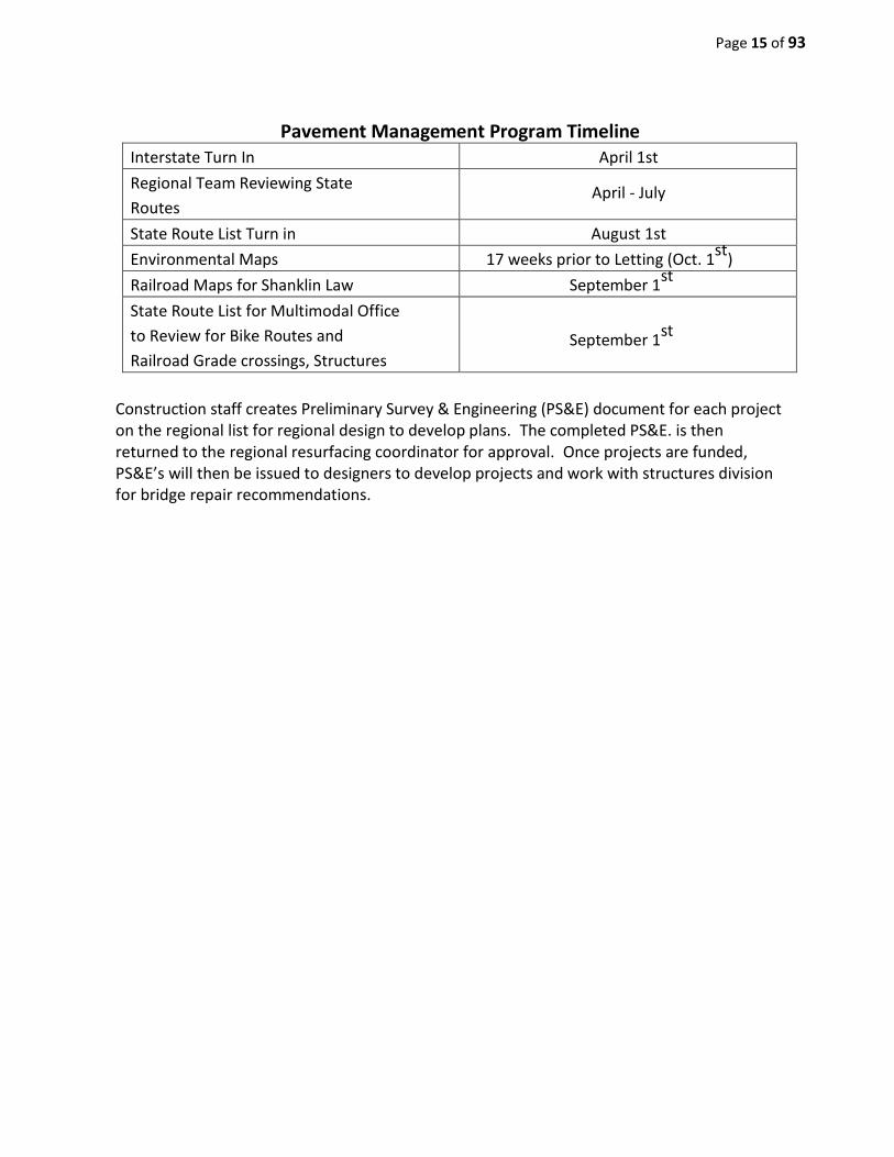
Pavement Management Program Timeline Interstate Turn In April 1st Regional Team Reviewing State Routes
April - July
State Route List Turn in August 1st Environmental Maps 17 weeks prior to Letting (Oct. 1st) Railroad Maps for Shanklin Law September 1st State Route List for Multimodal Office to Review for Bike Routes and Railroad Grade crossings, Structures
September 1st
Construction staff creates Preliminary Survey & Engineering (PS&E) document for each project on the regional list for regional design to develop plans. The completed PS&E. is then returned to the regional resurfacing coordinator for approval. Once projects are funded, PS&E’s will then be issued to designers to develop projects and work with structures division for bridge repair recommendations.
Page 16 of 93
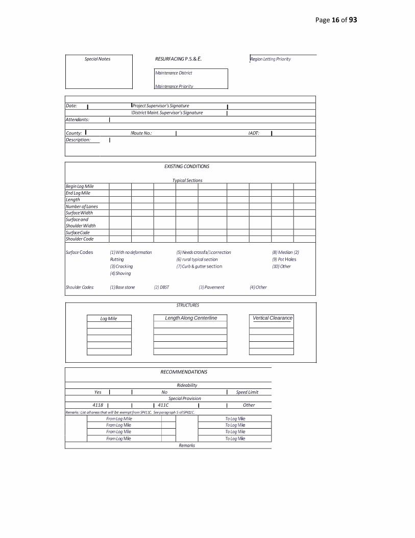
Length Along Centerline
Vertical Clearance
Special Notes
RESURFACING P.S.& E. Maintenance District Maintenance Priority
IRegion Letting Priority
Date: I IProject Supervisor's Signature I
! District Maint. Supervisor's Signature I Attendants: I County: I !Route No.: I I ADT: I Description: I
EXISTING CONDITIONS
Typical Sections
Begin Log Mile End Log Mile Length Number of Lanes Surface Width Surface and Shoulder Width
Surface Code Shoulder Code Surface Codes (1) With no deformation (5) Needs crossfa/1 correction (8) Median (2)
Rutting (6) rural typical section (9) Pot Holes (3) Cracking (7) Curb & gutter section (10) Other (4) Shoving
Shoulder Codes: (1) Base stone (2) DBST (3) Pavement (4) Other
STRUCTURES
Log Mile
RECOMMENDATIONS
Rideability Yes I I No I Speed Limit
Special Provision 4118 I I I 411C I I Other
Remarks: List all areas that will be exempt from SP411C. See paragraph 5 of SP411C.
From Log Mile To Log Mile From Log Mile To Log Mile From Log Mile To Log Mile From Log Mile To Log Mile
Remarks

Page 17 of 93
Mix Type Inches/Spread Rate Roadway Shoulder 'A-S' Mix "A' Mix "B'Mix 'C' Mix 'C-S'Mix 'BM' Mix
'BM-2' Mix Chip Seal
Mix Type Spread Rate Roadway Shoulder
2
"D' Mix "E'Mix
'C-W' Mix Microsurface
Thin Lift D Thin Lift Cs
OGFC
RESURFACING P.S.& E.
Material Transfer Device
I Special Provision 407G I I Yes I I I No I I
Drainage: Roadway Pipes Location (Log Mile)
Size Length
Side Drains
ILin. Ft of I in Ft of
Lin. Ft of
Ditching
(Cost to be included in other items) Log Mile Left Right Lin. Ft. Remarks
IIN_u_m_be_r_o_f_Ca_t_ch_B_a_s_in_s State Storm Drain Adjustments
l l IN_u_m_b_er_o_f_M_an_h_o_k_s l -- 1
Utilities Adjustments Type Number Owner
Sewer Manhole Telephone Manhole
Gas Valves Water Valves
Note. Designer needs to show owner on plans. Note. utility Owner responsible for own adjustments. I
I Base I Leveling I
I Surface I

Page 18 of 93
Location Length Width Depth
RESURFACING P.S.& E.
Remarks:
PG Grade Asphalt Recommended
lPG 64-22 I lPG 70-22 I lPG 76-22 I
Shoulder Stone ! Grading "D" Mineral Aggregate (depth x width x length)
I Cold Planing I
Spot Leveling
Type of Mix Tons
Removal & Disposal of Existing Bituminous Material
Location Length Depth Width
Estimated Tonnage for Replacement of Removal & Disposal of Existing Bituminous Material
Tons IType of Mix
Nightwork YES
Comments:
Workzone Restrictions (SP 1088) NO
Notes For Special Items or Work
3

Page 19 of 93
RESURFACING P.S.& E.
County Roads, City Streets, Driveways, Field Entrances, Intersections, & Business Entrances
Type LM Lt. Rt. Signal Loops Normal
Fix Extra Work
Remarks
4

Page 20 of 93
RESURFACING P.S.& E.
Specialty Markings
Quantity Unit Item Paint Thermo.
LM Item No.716-05.01 PAINT PVMT MK (4' Line) X LM Item No.716-05.20 PAINT PVMT MK (6' Line) X LF Item No.716-08.01 RMVL of PVMT MK (Line) Each Item No.716-0302 Plastic Word PVMT MK (RXR) X
LF Item No.716-02.03 Plastic PVMT MK (Crosswalk) X
LF Item No.716-02.09 Plasl PVMT MK (LNGTDNL X-WALK) X
SY Item No.716-02.04 Plastic PVMT MK (CHNZTN STRIP) X
LF Item No.716-02.05 Plastic PVMT MK (Stop Line) X
Each Item No.716-0303 Plastic Word PVMT MK (Slop Mead) X
LF Item No.716-02.02 Plastic PVMT Marking (8" Banier Une) X
Each Item No.716-03.01 Plastic Word PVMT MK (ONLY) X
LF Item No.716-02.11 Plastic PVMT Marl< (6" Dotted Une) X
Each Item No.716-01.10 Snow-Plowable Reffeclive Marker Each Item No.716-01.30 RMVL of SNWPLWBL RFLCT MRKR LM Item No.716-02.01 Plastic PVMT MK (4' Line) X
Each
-- -- --
i I i 716-04.05 716-02.06 716-04.02
Each Item No.716-0305 Plastic Word PVMT MK (Bike Lane) X
Each Item No.716-0411 Plasl PVMT MK (Bicycle Symb wlrider) X
Each Item No.716-04.13 Plastic PVMT MK (Bike Lane Anow) X
LM Item No. 411-10.01 Scoring Pavement LM Item No.716-1306 Spray Thermo Pavement Marking 40mil (4in line) X
LM Item No.716-02.10 Plastic Pavement Marking (6') X
Remarks: See Special Provisions 411RS & 716ST for final pavement marking details. Use
add#ional sheets, if sketch is needed.
Traffic Counters and Weather Stations Please Note any Traffic Counters and/or Weather Stations
Pavement Marking (striping breakdown)
% Passing I I % No Pass on One Side I I % No Pass on Both Sides I Remarks:
Alternate Transportation Mode Information
1.) Is this section of roadway included in an Urban IMetropolitan area which has an adopted Bicycle I Pedestrian transportation plan? Yes I
No I
2.) What type of bike improvement will be included with this maintenance action? A) Bike Lane B.) Wide Outside Lane C.) Share Use Roadway D.) None requested in the adopted plan.
Draw all Proposed Typical Sections.
5

Page 21 of 93
RESURFACING P.S.& E.
Guardrail (Federal Projects Only)
From Log Mile
To Log Mile
Side Item No. Item No. Item No. Item No..
Note: Use Additional sheets if needed for guardrail items.
6

Page 22 of 93
RESURFACING P.S.& E.
ADA RAMP REPAIR AND NEW INSTALLATIONS
Landmark (Intersection, Log Mile, etc.)
Check One Remarks (Location of Landmark, height of curb,obstacles,etc.) Repair New Install
7

Page 23 of 93
RESURFACING SAFETY REVIEW CHECKLIST
It is the intent of this checklist to identify iow cost safety improvements" that will provide improvements in the areas of lane departures/run-off-the-road crashes and pedestrian and bicycle safety on this route at a minimal cost. A review of the crash history data for this route will be necessary for completion of this checklist and should be affached to the final report. Special affention should be given to those areas identified in the crash history as "hot spots" where worl< should be accomplished to provide a significant improvement to safety
County Route Log Miles
AADT 1) Is shoulder width greater than 2' and MDT greater than 1500? If yes, provide rumble stripes on shoulder.
2) If MDT is greater than 1500 and sh011lders are not present or less than 2'wide, can minimum 2' shoulders be added without utility relocations or the purchase of ROW? If so, provide a minimum 2' shoulder
3) Repair and replace guarrlrail to wrrent TOOT standards At a minimum, end terminals should be brought up to wrrent standards
4) Is signing adequate and visible (placement, height, retroreflectivity, vegetation, etc.)? Does signing meet MUTCD requirements? Provide recommendations for upgrades and/or additional signing.
FOR CURVES
') Would the use of centerline nimble strips, rumble stripes, raised pavement markers or chevrons help delinate the curve?

Page 24 of 93
RESURFACING SAFETY REVIEW CHECKLIST
') Could the condition in curves be improved by correcting superelevation rates or widening shoulders without purchasing ROW orrelocating utilities?
') Would the construction of a specialized skid resistant surface improve conditions in wrves? If so, please explain.
5) Would the construction of a specialized ski</ resistant surface improve conditions in intersections? If so, please explain.
6) Are there roadside obstacles (trees, tree stumps more that 4" above the ground, utility poles, culverts, headwalls, mailboxes, etc.) present? If so, can they be addressed by one of the following. 1) Removal of the obstacle. 2) Redesign the obstacle so that it can be traversed 3) Relocate the obstacle to where it is less likely to be struck 4) Re<luce impact severity by using an appropriate breakaway device. 5) Shield the obstacle with a longitudinal barrier designed for redirection or use a crash cushion 6) Delineate the obstacle if the above alternatives are not appropriate.
f) Can improvements be made that would enhance pedestrian or bicycle salety (the acldition of a bike lane, share the road signing, enhancement or upgrading crosswalks to T.D 0.T. standards)? Is the addition of approved handicap ramps needed to comply with ADA standards?
8) Could improvements be made to ditches to assure proper drainage andfor to reshape ditches to mitigate substandard fares/ope or backs/ope without the relocation of utilities or purchase of R 0.W.?
9) Is the use of a Safety Edge required for this project? A Safety Edge should be specified where the drop-off affer [ paving is greater than 1 '!i inches (see sketch)
25 -30 degrees
Old Pavement

Page 25 of 93
PAVEMENT TREATMENT GUIDELINES

Page 27 of 93
Revised: May 6, 2013 RESURFACING CHEAT SHEET
Type of Treatment
Item Numbers Spread RateTack Coat
RateRideablitly
Special Notes
Temporary Striping
Thermo and Rumbles
Guardrail End
TerminalsBike
Safety Edge
ADA Ramps
Chip Seal405-01.01 (Bituminous Material) 405-01.02 (Mineral Aggregate)
0.30 Gal /SY (Emulsioin); 24
lbs/SY (Aggregate) #7 Stone unless
otherwise noted.
NA NO NA YESSee Design
Guideline Table 4-3
Add 25 Tons of 303-01 per terminal
Include catch basin adjustment item(if needed), Type B Safety
Grates (if needed); Striping plan from City, Include items in Est.
Qty Sheet
NOAssume 90
Square Feet per Ramp **
Fog Seal 403-05 (Fog Seal) 0.12 Gal/SY NA NO NA NOSee Design
Guideline Table 4-3
Add 25 Tons of 303-01 per terminal
Include catch basin adjustment item(if needed), Type B Safety
Grates (if needed); Striping plan from City, Include items in Est.
Qty Sheet
NOAssume 90
Square Feet per Ramp **
Microsurfacing 1 Lift414-03.01 (Emulsifed Asphalt for Microsurfacing) 414-03.02 (Aggregate for Microsurfacing)
22 lbs/SY
0.10 Gal/SY (Product is
dilluted 3:1, divide total by
4)
NO NA NO
Include Item for Grinding Thermo;
See Design Guideline Table 4-3
*
Add 25 Tons of 303-01 per terminal
Include catch basin adjustment item(if needed), Type B Safety
Grates (if needed); Striping plan from City, Include items in Est.
Qty Sheet
NOAssume 90
Square Feet per Ramp **
Microsurfacing 2 Lifts414-03.01 (Emulsifed Asphalt for Microsurfacing) 414-03.02 (Aggregate for Microsurfacing)
32 lbs/SY
0.10 Gal/SY (Product is
dilluted 3:1, divide total by 4). Only Tack
first lift.
NO NA YES
Include Item for Grinding Thermo;
Include Temporary Paint; See Design
Guideline Table 4-3 *
Add 25 Tons of 303-01 per terminal
Include catch basin adjustment item(if needed), Type B Safety
Grates (if needed); Striping plan from City, Include items in Est.
Qty Sheet
NOAssume 90
Square Feet per Ramp **
Thin Lift D411-03.12 (PG 64-22); 411-03.13 (PG 70-22); 411-03.14 (PG 76-22)
85 lbs/SY 0.08 Gal/SY NO NA NOSee Design
Guideline Table 4-3 *
Add 25 Tons of 303-01 per terminal
Include catch basin adjustment item(if needed), Type B Safety
Grates (if needed); Striping plan from City, Include items in Est.
Qty Sheet
NOAssume 90
Square Feet per Ramp **
Thin Lift Cs411-03.07 (PG 64-22); 411-03.08 (PG 70-22); 411-03.09 (PG 76-22)
65 lbs/SY 0.08 Gal/SY NO NA NOSee Design
Guideline Table 4-3 *
Add 25 Tons of 303-01 per terminal
Include catch basin adjustment item(if needed), Type B Safety
Grates (if needed); Striping plan from City, Include items in Est.
Qty Sheet
NOAssume 90
Square Feet per Ramp **
411-D411-01.10 (PG 64-22); 411-02.10 (PG70-22); 411-03.10 (PG 76-22)
132.5 lbs/SY 0.08 Gal/SY YES NA NOSee Design
Guideline Table 4-3
Add 25 Tons of 303-01 per terminal
Include catch basin adjustment item(if needed), Type B Safety
Grates (if needed); Striping plan from City, Include items in Est.
Qty Sheet
Include Footnote for
SP 407SE
Assume 90 Square Feet per Ramp **
Chip Seal with Thin Lift D
See above for Items See above 0.08 Gal/SY NO See above YESSee Design
Guideline Table 4-3 *
Add 25 Tons of 303-01 per terminal
Include catch basin adjustment item(if needed), Type B Safety
Grates (if needed); Striping plan from City, Include items in Est.
Qty Sheet
NOAssume 90
Square Feet per Ramp **
Chip Seal with Thin Lift Cs
See above for Items See above 0.08 Gal/SY NO See above YESSee Design
Guideline Table 4-3 *
Add 25 Tons of 303-01 per terminal
Include catch basin adjustment item(if needed), Type B Safety
Grates (if needed); Striping plan from City, Include items in Est.
Qty Sheet
NOAssume 90
Square Feet per Ramp **
Chip Seal with Microsurfacing (1 Lift)
See above for ItemsSee above and 24 lbs/SY for Micro
0.08 Gal/SY NO See above YESSee Design
Guideline Table 4-3 *
Add 25 Tons of 303-01 per terminal
Include catch basin adjustment item(if needed), Type B Safety
Grates (if needed); Striping plan from City, Include items in Est.
Qty Sheet
NOAssume 90
Square Feet per Ramp **
Chip Seal with 411-D See above for Items See above 0.08 Gal/SY YES See above YESSee Design
Guideline Table 4-3
Add 25 Tons of 303-01 per terminal
Include catch basin adjustment item(if needed), Type B Safety
Grates (if needed); Striping plan from City, Include items in Est.
Qty Sheet
Include Footnote for
SP 407SE
Assume 90 Square Feet per Ramp **
Cs and 411-D307-01.15 and See above for Items
See above 0.08 Gal/SY YES NA YESSee Design
Guideline Table 4-3
Add 25 Tons of 303-01 per terminal
Include catch basin adjustment item(if needed), Type B Safety
Grates (if needed); Striping plan from City, Include items in Est.
Qty Sheet
Include Footnote for
SP 407SE
Assume 90 Square Feet per Ramp **
Mill and 411-D415-01.01 and See above for items
See above 0.08 Gal/SY YES NA NOSee Design
Guideline Table 4-3
Add 25 Tons of 303-01 per terminal
Include catch basin adjustment item(if needed), Type B Safety
Grates (if needed); Striping plan from City, Include items in Est.
Qty Sheet
NOAssume 90
Square Feet per Ramp **
Alternates
414-03.03( Microsurfacing); 411-03.05 (Thin Lift Cs); 411-03.17 (Thin Lift D); 415-01.02 (Cold Planing)
See above Depends Depends NA DependsSee Design
Guideline Table 4-3
Add 25 Tons of 303-01 per terminal
Include catch basin adjustment item(if needed), Type B Safety
Grates (if needed); Striping plan from City, Include items in Est.
Qty Sheet
DependsAssume 90
Square Feet per Ramp **
* Will need a Footnote on Estimated Quantites specifying a depth that is different from Standard Drawing.
* * This quantitiy will increase with the height of the curb. Please check this and adjust accordingly.
Page 28 of 93
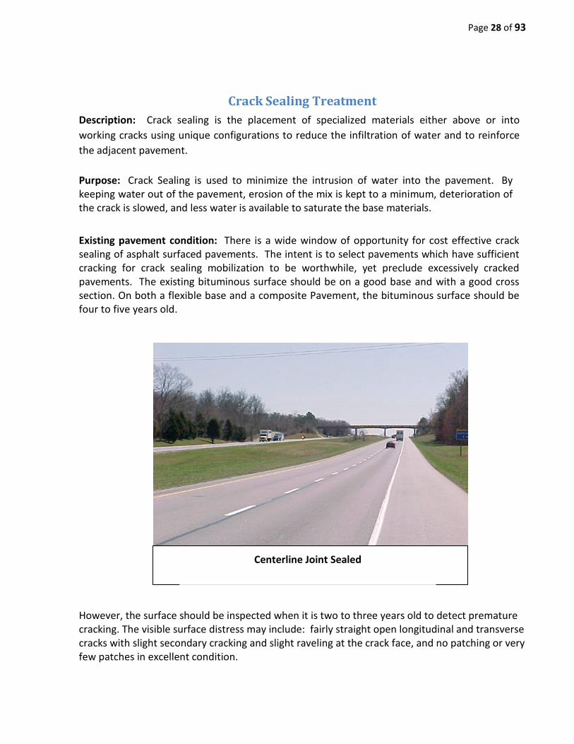
Crack Sealing Treatment Description: Crack sealing is the placement of specialized materials either above or into working cracks using unique configurations to reduce the infiltration of water and to reinforce the adjacent pavement. Purpose: Crack Sealing is used to minimize the intrusion of water into the pavement. By keeping water out of the pavement, erosion of the mix is kept to a minimum, deterioration of the crack is slowed, and less water is available to saturate the base materials. Existing pavement condition: There is a wide window of opportunity for cost effective crack sealing of asphalt surfaced pavements. The intent is to select pavements which have sufficient cracking for crack sealing mobilization to be worthwhile, yet preclude excessively cracked pavements. The existing bituminous surface should be on a good base and with a good cross section. On both a flexible base and a composite Pavement, the bituminous surface should be four to five years old.
However, the surface should be inspected when it is two to three years old to detect premature cracking. The visible surface distress may include: fairly straight open longitudinal and transverse cracks with slight secondary cracking and slight raveling at the crack face, and no patching or very few patches in excellent condition.
Centerline Joint Sealed

Page 29 of 93
Existing pavement surface preparation: None Performance: The effectiveness of the seal will greatly depend upon the width of crack being sealed and the movement of the pavement structure at the crack.
Life Extension Pavement Years
Flexible Up to 3 Composite Up to 3 The time range is the expected life extending benefit given to the pavement, not the anticipated longevity of the treatment.
Performance Limitations: Generally, all cracks in the traveled lanes and the shoulder areas should be filled. Transverse cracks that have excessive secondary cracking around the main crack should not be individually sealed. The presence of this type of transverse crack is an indication that the pavement surface may warrant a more extensive pavement surface treatment. Crack sealing materials should be aged at least one year prior to micro-surfacing, any type of Hot Mix Overlay, or a Polymer Modified Asphalt Concrete.
Excessive crack sealing of secondary cracks creating safety concerns
This treatment is not a one-shot operation. In order to maintain the sealed pavement surface, this treatment should be followed up by a routine maintenance crack sealing or crack filling operation when additional cracks develop. Care should be taken when doing additional sealing so as not to seal extensive secondary cracks that will result in a safety problem.
Quantity of crack seal is excellent; however, longitudinal crack seal is too heavy.

Page 30 of 93
Fog Seal Description: Fog seals are a light application of diluted asphalt emulsion placed directly on the pavement surface. Purpose: Fog seals are used to seal the pavement, inhibit raveling, and provide some enrichment to a hardened and oxidized AC surface. Existing pavement condition: Fog seals are most effective when applied on a pavement in relatively good condition with minor cracks and some surface raveling or oxidation. Existing pavement surface preparation: Repair and patch all major pavement defects. All cracks, other than hairline cracks, should be filled with suitable bituminous crack filler. Scrape all oil spots to remove excess oil and dirt. Just before applying the fog sealer clean the asphalt surface of all loose dust, dirt and other debris. Performance: Fog seals generally last about one to four years before the pavement requires either another application or the placement of a more substantial surface restoration treatment. Fog seals are a low-cost means of rejuvenating the surface of the pavement and inhibiting raveling, and when placed early enough in the life of the pavement, can be effective at prolonging its life.
Life Extension Pavement Years
Flexible Up to 4 Composite Up to 4
Performance Limitations: Fog seals are not effective for sealing a pavement surface with cracks. They do not repair potholes, cracks, or major raveling. Repeated applications of a fog seal at regular intervals increases its effectiveness. Fog seals may also be an immediate remedy to address a surface course constructed with low asphalt content. Aggregate shall be included to boost frictional properties if process is used on roadway.

Page 31 of 93
Longitudinal Joint Stabilization
Description: The weakest section of the pavement is the longitudinal construction joint between traffic lanes. Longitudinal Joint Stabilization is a method to rejuvenate and seal the longitudinal construction joint. This treatment should be applied within two to three years of the pavement’s resurfacing.
Existing pavement condition: Longitudinal joint stabilization treatment is most effective when applied on a pavement in relatively good condition. Existing pavement surface preparation: Ensure surface is in a clean and dry condition.
Life Extension Pavement Years
Flexible 3 Years Performance Limitations: Reflectivity of pavement markings is temporarily reduced until material is worn off of pavement markings. Treatment cannot be utilized on lanes adjacent to fog sealed areas
Page 32 of 93
Slurry Seal
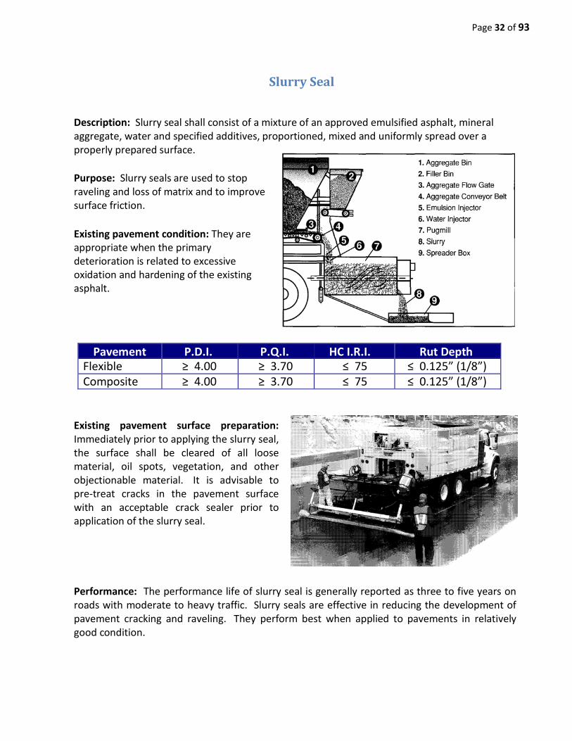
Description: Slurry seal shall consist of a mixture of an approved emulsified asphalt, mineral aggregate, water and specified additives, proportioned, mixed and uniformly spread over a properly prepared surface. Purpose: Slurry seals are used to stop raveling and loss of matrix and to improve surface friction. Existing pavement condition: They are appropriate when the primary deterioration is related to excessive oxidation and hardening of the existing asphalt.
Pavement P.D.I. P.Q.I. HC I.R.I. Rut Depth Flexible ≥ 4.00 ≥ 3.70 ≤ 75 ≤ 0.125” (1/8”) Composite ≥ 4.00 ≥ 3.70 ≤ 75 ≤ 0.125” (1/8”)
Existing pavement surface preparation: Immediately prior to applying the slurry seal, the surface shall be cleared of all loose material, oil spots, vegetation, and other objectionable material. It is advisable to pre-treat cracks in the pavement surface with an acceptable crack sealer prior to application of the slurry seal.
Performance: The performance life of slurry seal is generally reported as three to five years on roads with moderate to heavy traffic. Slurry seals are effective in reducing the development of pavement cracking and raveling. They perform best when applied to pavements in relatively good condition.

Page 33 of 93
Life Extension Pavement Years
Flexible Up to 5 Years Composite Up to 4 Years
Performance Limitations: Slurry seals should not be used on deteriorated pavements. Localized areas of severe distress should be patched prior to the application of the slurry seal. Working cracks should be sealed with a crack sealant, and the presence of a substantial number of wide or working cracks may indicate slurry seals are not an appropriate measure.

Page 34 of 93
Microsurfacing Description: Micro-surfacing is a type of slurry seal that uses a polymer-modified emulsion binder, higher quality aggregates, and a set control additive. Purpose: A single course micro-surface has been used effectively to improve surface friction characteristics and to seal the pavement surface, thereby addressing oxidation and raveling. A multiple course micro-surface has been used to correct certain pavement surface deficiencies including severe rutting, minor surface profile irregularities, polished aggregate or low skid resistance and light to moderate raveling. Existing pavement condition: Micro- surfacing does not add significant structure to the existing pavement, so its use should be limited to pavements exhibiting little structural deterioration. The pavement should exhibit a uniform cross section and a good base. The visible surface distress may include slight cracking, rutting, minor surface irregularities, flushed or polished surface and/or moderate raveling.
Single Application @ 22 lbs./s.y.
Pavement P.D.I. P.Q.I. HC I.R.I. Rut Depth Flexible ≥ 4.00 ≥ 3.70 ≤ 75 ≤ 0.125” (1/8”) Composite ≥ 4.00 ≥ 3.70 ≤ 75 ≤ 0.125” (1/8”)
Double Application @ 32 lbs./s.y. (18 lb. & 14 lb. Lifts)
Pavement P.D.I. P.Q.I. HC I.R.I. Rut Depth Flexible ≥ 4.00 ≥ 3.70 ≤ 75 <0.125” Composite ≥ 4.00 ≥ 3.70 ≤ 75 < 0.125”
SR 290- Putnam County- 10 Year old Pavement

Page 35 of 93
Existing pavement surface preparation: Pavements with fatigue cracking and/or significant linear cracking are not candidates for micro-surfacing unless these deteriorated areas are repaired prior to the placement of the micro- surfacing. Micro-surface is well suited to filling ruts on an otherwise sound pavement. Immediately prior to applying the micro-surface, the surface shall be cleared of all loose material, silt spots, vegetation, and other objectionable material. Performance: This treatment corrects rutting, flushing and low friction. The service life of micro-surface is generally reported to be about six to eight years. However, in judging its performance, it must be recognized that micro-surface can be placed for different reasons and therefore its performance is tied closely to its application.
Life Extension Pavement Years
Flexible 6 to 8 Composite 5 to 7
Performance Limitations: A standard micro-surface formulation should not be used on a pavement with moderate to heavy surface cracks. Micro-surface mixes require warm to moderate temperatures for curing; caution is recommended for late season nighttime work.
SR 290 - Putnam County – Minor rutting and cracking. Single course micro-surface.

Page 36 of 93
Extensive cracking from oxidized pavement, no structural damage
Scrub Seal Description: The scrub seal process provides an economical treatment that fills cracks, rejuvenates worn asphalt pavement and provides a durable wearing course. Scrub seals are also used to provide a membrane with resistance to reflective cracking. Purpose: The primary purpose of the scrub seal treatment is to fill cracks and seal the asphalt pavement. Existing pavement condition: Scrub seal is not intended to improve the structural condition of the pavement. Therefore, the seal should only be used on stable asphalt pavements that are dry, oxidized and cracked.
Ribbon of material in front of broom for filling cracks
Existing pavement surface preparation: The pavement shall be cleaned of all lose dirt, vegetation and other objectionable material prior to the application to the scrub seal. Performance: Scrub seal has an estimated life of six years. The scrub seal rejuvenates the existing pavement, seals existing pavement, fills cracks and voids, and provides a skid-resistant wearing surface.
Life Extension
Pavement Years Flexible Up to 6 Years Composite Up to 6 Years
Performance Limitations: The emulsion bonds to the cracks and seals them from water

Page 37 of 93
damage. Pavements with a poor subgrade are not good candidates for a scrub seal.
Application of asphalt sealer Aggregate applied to asphalt sealer
Brooming of aggregate cover material Rolling of aggregate cover material – 2 passes

Page 38 of 93
Scrub Seal approximately one year after placement salt is present from winter treatment

Page 39 of 93
CRS2P Chip Seal with a Fog Seal Description: The chip seal process provides an economical treatment that fills cracks, rejuvenates worn asphalt pavement and provides a durable wearing course. Scrub seals are also used to provide a membrane with resistance to reflective cracking. Purpose: The primary purpose of the chip seal treatment is to fill cracks and seal the asphalt pavement. When appropriate, chip seal treatments should be considered as a treatment when ADT’s are less than 750. Fog Seal Applied after Chip Seal is complete to help curing and lock aggregate in place
Existing pavement condition: Chip seal is not intended to improve the structural condition of the pavement. Therefore the seal should only be used on stable asphalt pavements that are dry, oxidized and cracked.

Page 40 of 93
Extensive cracking from oxidized pavement, no structural damage
Existing pavement surface preparation: The pavement shall be cleaned of all lose dirt, vegetation and other objectionable material prior to the application to the chip seal.
Application Rates: Material Rate
Emulsion (CRS2P w/ #7 chips) 0.35 gals/sy Aggregate (#7 chips) 22#/sy
Emulsion (CRS2P w/ #8 chips) 0.30 gals/sy Aggregate (#8 chips) 20#/sy
Fog Seal 0.10 gals/sy
Performance: Chip seal has an estimated life of six years. The chip seal rejuvenates the existing pavement, seals existing pavement, fills cracks and voids, and provides a skid resistant wearing surface.
Life Extension Pavement Years
Flexible 6 Years
Performance Limitations: The emulsion bonds to the cracks and seals them from water damage. Pavements with a poor subgrade are not good candidates for a chip seal.

Page 41 of 93
Aggregate applied to asphalt sealer Rolling of aggregate cover material – 2 passes
Completed Chip Seal w/ Fog Seal

Page 42 of 93
Thin Overlay Treatment Description: A thin hot mix asphalt (HMA) overlay is one of the best available alternatives in the pavement preventive maintenance program. A minor amount of structural improvement is provided with this strategy. To qualify as preventive maintenance, an HMA mixture is limited to 1-3/4” in thickness as an overlay. Some of the mixes that meet these guidelines are:
• 1-1/4” of “D” mix • 3/4” Thin Lift “D” mix • 5/8” Thin Lift mix • Any of the above with Scratch Mix included as spot leveling and rut correction.
Use of shuttle buggy on thin overlay.
“D” Mix (1 ¼”) – This type of treatment is the flagship mix for the Department. The Department uses approximately 75% of its state route resurfacing budget on this type of treatment. This treatment is typically used on higher ADT routes and on more heavily distressed roadways. Occasionally “D” Mix is used to add structure to routes inherited from the counties in the 1982 Road Program Act. Thin Lift “D” Mix (3/4”) – This type of mix is similar to the “D” Mix minus the ½” aggregate. This mix allows approximately a 30% cost savings to the Department for roadways that exhibit less distress as described above. This treatment is typically applied to roadways with low-to-moderate ADT volumes and minor-to-moderate cracking. Thin Lift Mix (5/8”) – This treatment is typically applied to routes with low ADT volumes that exhibit little or no distress. This treatment is sometimes considered as an alternate to micro-surfacing. This treatment is only successful as a preservation treatment to combat oxidation of the wearing. No structural improvement and little or no improvement in roadway smoothness can be anticipated.
Purpose: Thin overlays protect the pavement structure, reduce the rate of pavement deterioration, correct surface deficiencies, reduce permeability and improve the ride quality of the pavement.

Page 43 of 93
Existing pavement condition: The existing pavement should exhibit a good base condition and a uniform cross section. The visible surface distress may include moderate raveling, longitudinal and transverse cracks and small amounts of block cracking. Only minor base failures and depressions should be present.
“D” Mix (1 ¼”) Pavement Rut Depth P.S.I. P.D.I. P.Q.I.
Flexible ≤ 0.25” ≥ 3.20 ≥ 3.60 ≥ 3.50 Composite ≤ 0.25” ≥ 2.80 ≥ 3.30 ≥ 3.20
Thin Lift “D” Mix (3/4”) Pavement Rut Depth P.S.I. P.D.I. P.Q.I.
Flexible ≤ 0.125” ≥ 3.20 ≥ 3.90 ≥ 3.70
Thin Lift Mix (5/8”) Pavement Rut Depth P.S.I. P.D.I. P.Q.I.
Flexible ≤ 0.125” ≥ 3.50 ≥ 4.00 ≥ 3.70
Existing pavement surface preparation: The preparation work should be limited to the repair of the minor base failures and depressions, the filling of voids in the pavement surface, the removal of any patched area with poor adhesion or a very high asphalt content that may bleed up through the new bituminous surface. Performance: This treatment performs best on flexible pavement structures, but is also applicable to composite pavements depending on the extent of the reflective cracking. A material transfer device, such as a shuttle buggy, is required on any roadway with sufficient clearance.
Life Extension (“D” Mix @ 1 ¼”) Pavement Years
Flexible 12 Years Composite 10 Years
Life Extension (Thin Lift “D” Mix @ ¾”)
Pavement Years Flexible 10 Years
Life Extension Thin Lift Mix (@ 5/8”) Pavement Years
Flexible 6 Years

Page 44 of 93
Performance Limitations: A thin HMA overlay should not be placed on the following existing pavement conditions: severely distressed composite pavement, severely raveling or rutted bituminous pavement, pavement with a weak base, or a bituminous surface that is debonding.
SR 111 - White County - 1-1/4" "D" Mix with 2-foot taper on shoulders

Page 45 of 93
Chip Seal with Thin Hot Mix Overlay Description: The chip seal process provides an economical treatment that fills cracks, rejuvenates worn asphalt pavement and provides a durable wearing course. The thin overlay provides a smooth and more durable riding surface that looks similar to a thin mix overlay or to 411 D overlay. Purpose: The primary purpose of this dual treatment is to mitigate top-down cracking on an older (but healthy) pavement. This treatment can be a cheaper alternative to a milling and overlay project and add some additional structure. Chip seals need to be done on the correct route. Not all routes are good candidates due to being in town or in a residential area. These tend to be rural area projects.
Chip Seal prior to Thin Lift of Hot Mix Asphalt being placed

Page 46 of 93
Existing pavement condition: There are only two sure ways to mitigate top-down cracking in a pavement: By milling and replacing or by using a polymerized chip seal. The chip seal will fill cracks and the aggregate will be used as a crack relief layer. A chip seal is not intended to improve the structural condition of the pavement. Therefore, the seal should only be used on stable asphalt pavements that are dry, oxidized and cracked.
Extensive cracking from oxidized pavement, no structural damage
Existing pavement surface preparation: The pavement shall be cleaned of all lose dirt, vegetation and other objectionable material prior to the application to the chip seal.
Application Rates for Chip Seal: Material Rate
Emulsion (CRS2P w/ #7 chips) 0.35 gals/sy Aggregate (#7 chips) 22#/sy
Emulsion (CRS2P w/ #8 chips) 0.30 gals/sy Aggregate (#8 chips) 20#/sy
Fog Seal 0.10 gals/sy
Thin Lift “D” Mix (3/4”) Pavement Rut Depth P.S.I. P.D.I. P.Q.I.
Flexible ≤ 0.125” ≥ 2.90 ≥ 3.50 ≥ 3.40
Thin Lift Mix (5/8”) Pavement Rut Depth P.S.I. P.D.I. P.Q.I. Flexible ≤ 0.125” ≥ 3.2 ≥ 3.5 ≥ 3.50

Page 47 of 93
Performance: Chip seal and thin hot mix overlay has an estimated life of 12 years. The chip seal rejuvenates the existing pavement, seals existing pavement, fills cracks and voids, and the thin lift of hot mix asphalt provides a very durable and smooth riding surface.
Life Extension Pavement Years
Flexible 12 Years Performance Limitations: The emulsion bonds to the cracks and seals them from water damage. Pavements with a poor subgrade are not good candidates for a chip seal.
CRS2P Emulsion filling the cracks prior to aggregate being dropped
Completed Chip Seal with Thin Overlay

Page 48 of 93
Cape Seal Description: A cape seal is a polymerized chip seal treatment that is topped with one layer of micro-surfacing. The chip seal process provides an economical treatment that fills cracks, provides a crack relief layer to mitigate reflective cracking in the future and the micro-surfacing provides a riding surface. Purpose: The primary purpose of this dual treatment is to mitigate top down cracking onan older (but healthy) pavement. This treatment can be a cheaper alternative to a milling and overlay project and add some additional structure. Chip seals need to be done on the correct route. Not all routes are good candidates due to being in town or in a residential area. These tend to be rural area projects.
Chip Seal prior to Microsurfacing Lift being placed

Page 49 of 93
Extensive cracking from oxidized pavement, no structural damage
Existing pavement condition: There are only two sure ways to mitigate top-down cracking in a pavement: by milling and replacing or by using a polymerized chip seal. The chip seal will fill cracks and the aggregate will be used as a crack relief layer. A chip seal is not intended to improve the structural condition of the pavement. Therefore, the seal should only be used on stable asphalt pavements that are dry, oxidized and cracked. Microsurfacing cannot improve smoothness because of a lack of afloating screed. The existing pavement will need to have a smoother surface (similar to a Microsurfacing candidate) but with top-down cracking.
Existing pavement surface preparation: The pavement shall be cleaned of all lose dirt, vegetation and other objectionable material prior to the application to the chip seal.
Application Rates for Chip Seal: Material Rate
Emulsion (CRS2P w/ #7 chips) 0.35 gals/sy Aggregate (#7 chips) 22#/sy
Emulsion (CRS2P w/ #8 chips) 0.30 gals/sy Aggregate (#8 chips) 20#/sy
Fog Seal 0.10 gals/sy
Microsurfacing Single Application @ 24 lbs./s.y.
Pavement P.D.I. P.Q.I. Rut Depth Flexible ≥ 3.5 ≥ 3.90 ≤ 0.125” (1/8”)
Performance: Chip seal and Microsurfacing has an estimated life of ten years. The chip seal rejuvenates the existing pavement, seals existing pavement, fills cracks and voids, and the Microsurfacing provides a very durable and smooth riding surface.
Life Extension Pavement Years
Flexible 10 Years

Page 50 of 93
Performance Limitations: The emulsion bonds to the cracks and seals them from water damage. Pavements with a poor subgrade are not good candidates for this process.
CRS2P Emulsion filling the cracks prior to aggregate being dropped
Completed Chip Seal with 24 lbs/SY Microsurfacing

Page 51 of 93
Mill and Replace Treatment Description: The removal of an existing bituminous surface by the cold milling method and the placement of a HMA mixture limited to a depth of 1-1/4”. The new inlay (1 ¼” “D” mix or ¾” Thin Lift “D” mix) replaces the surface removed. Purpose: In preventive maintenance cold milling is used for the restoration of cross slopes, correct specific existing surface deficiencies, and produces a more economical project as compared to an overlay project. The inlay replaces the surface material removed by cold milling. Existing pavement condition: The existing pavement should exhibit a good base condition. The visible surface distress may include: severe surface raveling, multiple longitudinal and transverse cracking with slight raveling, a small amount of block cracking, patching in fair condition, debonding surface and slight to moderate rutting. The cold milling operation is used to correct rutting in the existing bituminous surface layer where the rutting is not caused by a weak base and when the condition of the existing pavement has deteriorated to a point where it is not practical to correct the rutting problem by a more economical treatment. The cold milling operation is also used to remove an existing bituminous course that is debonding. Existing pavement crown and super-elevation sections that have been identified as having a relationship to accidents can be modified by cold milling. In a curb-and-gutter section, cold milling can be used
Milling machine and water truck
to remove a portion of the existing surface to retain the existing curb face. Cold milling can also be used in those areas where the existing pavement grade cannot be raised.
Mill & “D” Mix (1 ¼”) Pavement Rut Depth P.S.I. P.D.I. P.Q.I.
Flexible > 0.250” < 2.90 < 3.50 < 3.40
Mill & Thin Lift “D” Mix (3/4”) Pavement Rut Depth P.S.I. P.D.I. P.Q.I.
Flexible > 0.250” < 3.10 < 3.70 < 3.60
Existing pavement surface preparation: None.

Page 52 of 93
Performance: This type of treatment will protect the remaining pavement structure, slow the rate of deterioration and improve the ride quality. This treatment performs best on flexible pavement structures, but is also applicable to composite pavements depending on the extent of the reflective cracking. A material transfer device, such as a shuttle buggy, is required on any roadway with sufficient clearance.
Milling machine in operation
Mill & “D” Mix (1 ¼”)
Pavement Years Flexible 12 Years
Mill & Thin Lift “D” Mix (3/4”) Pavement Years
Flexible 10 Years
Performance Limitations: This treatment should not be used on an existing pavement that shows evidence of a weak base.

Page 53 of 93
Under-drain Outlet Cleaning and Repair
Description: This work includes the clean out and repairs of the rigid PVC or corrugated plastic transverse drains from outlet ending to the connection with the mainline longitudinal drain. The work consists of cleaning silt, debris and vegetation at under-drain outlets, as well as replacing crushed or destroyed outlets as needed. Purpose: This work is intended to preserve and maintain the performance of the pavement drainage system. The installation of a drainage system improves the long term load carrying and load distribution properties of the base, subbase and subgrade materials by removing the free water which can decrease the stiffness of these load-carrying layers. The clean out and repair will help re-establish the effectiveness of the under-drain drainage system. Existing pavement condition: There are no unique pavement condition parameters which indicate drainage preservation is needed. However, drainage preservation is a critical activity for pavements. This work should be conducted on all pavements which have under-drain systems as a routine maintenance item, regardless of the condition of the pavement. Performance: Free-draining pipe outlets must be provided to ensure that the system drains properly. The system is severely limited by outlets being restricted due to siltation and vegetation growth. When this occurs, the system originally designed for drainage becomes a water storage system that feeds moisture to the pavement. End wall restricted by siltation and vegetation

Page 54 of 93
Performance Limitations: To prevent animals from nesting in the pipe, the headwall has a removable screen which allows for cleaning. Drainage systems that cease to drain become water storage reservoirs. This in turn contributes to the moisture problem instead of assisting in its resolution. Outlet markers aid in ensuring the system will be maintained and protected. They alert mowing and maintenance crews of the presence of an outlet and serve as a reminder that the system is present.
End wall properly functioning Rodent guard in end wall
Under-drain marked on shoulder Under-drain location needs remarking
Page 55 of 93
MINOR REHABILITATION

Page 56 of 93
Rehabilitation is the next pavement treatment in the Pavement Management Program following preventive maintenance. Rehabilitation is divided into two (2) categories: (1) Minor rehabilitation & (2) Major rehabilitation. Minor rehabilitation is necessary when repair costs to the pavement exceed the benefits derived from preventive maintenance treatments or when pavement structure needs to be increased. Major rehabilitation is necessary when the pavement deteriorates due to structural deficiencies or structural failure. Minor rehabilitation is limited to a pavement thickness of 2 ¾”, with a possible milling depth of up to 1 ¼”. Major rehabilitation requires a pavement thickness greater than 2 ¾”, with a possible milling depth greater than 1 ¼”. Since both types of rehabilitation (minor or major) encompass an extensive amount of work to elevate the pavement to an acceptable service level, as well as an excessive cost to perform the work, these treatments are typically delayed until sufficient funds can be set aside without having a significant impact to the Pavement Management Program. Therefore, these sections of roadway are generally addressed through reactive maintenance until the funding for the extensive work can be obligated. Historically, each region will perform only one of these treatments (either minor or major rehabilitation) once every two to three years. The Pavement Management Program includes the following minor rehabilitation treatments: Flexible and Composite Pavement Treatments -Leveling Course and Thin Overlay -Binder Course and Thin Overlay -Milling (≤1-1/4”), Leveling Course, and Thin Overlay -Milling (≤1-1/4”), Binder Course, and Thin Overlay -Performance Grade Leveling Course and Performance Grade Thin Overlay -Performance Grade Binder Course and Performance Grade Thin Overlay -Milling (≤1-1/4”), Performance Grade Leveling Course, and Performance Grade Thin Overlay
-Milling (≤1-1/4”), Performance Grade Binder Course, and Performance Grade Thin Overlay The Pavement Management Program includes the following major rehabilitation treatments:

Page 57 of 93
Flexible and Composite Pavement Treatment -Binder Course and Thin Overlay -Milling (≥1-1/4”), Binder Course, and Thin Overlay -Performance Grade Binder Course and Performance Grade Thin Overlay -Milling (≥1-1/4”), Performance Grade Binder Course, and Performance Grade Thin Overlay
Some mixes which are used in addition to the wearing surface treatment can include the following: Binders - “B-M” or “B-M2” mix (1 ½” to 2” depth) or Leveling - “C-W” mix (1 ½” depth) or “CS” mix (5/8” depth). Project selection for both minor and major rehabilitation will use data from the Pavement Management System (PMS) and visual inspection. A high priority for selection will be given to age and the overall pavement quality index (PQI). Both rehabilitation processes requires a PQI of less than 2.3. The PQI is derived from the pavement serviceability index (PSI) and the pavement distress index (PDI). DeKalb County - SR 26 - Binder Placement Placement of "B-M" Mix at 1-1/2" The PSI is determined from roughness via the International Roughness Index (IRI), rutting depth, and the severity and frequency of the distresses. These indexes are used statewide and will insure all rehabilitation treatment selections are consistent with the Department’s pavement strategies. The visual inspection will be a manual pavement distress survey. Each travel lane of the project shall be divided into one-mile sections. Each one-mile section will be further divided into one-tenth mile segments. A review of a minimum of one segment of each section within the project limits will be made. Keep in mind that pavement management data could be 2 years old and the pavement could have deteriorated significantly in that time. Visual inspections are crucial to justify the need for extra structural work.
Page 58 of 93
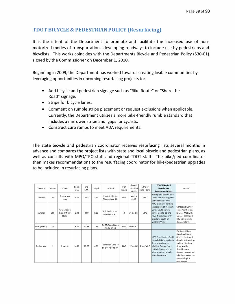
TDOT BICYCLE & PEDESTRIAN POLICY (Resurfacing) It is the intent of the Department to promote and facilitate the increased use of non-motorized modes of transportation, developing roadways to include use by pedestrians and bicyclists. This works coincides with the Departments Bicycle and Pedestrian Policy (530-01) signed by the Commissioner on December 1, 2010. Beginning in 2009, the Department has worked towards creating livable communities by leveraging opportunities in upcoming resurfacing projects to:
• Add bicycle and pedestrian signage such as “Bike Route” or “Share the Road” signage.
• Stripe for bicycle lanes. • Comment on rumble stripe placement or request exclusions when applicable.
Currently, the Department utilizes a more bike-friendly rumble standard that includes a narrower stripe and gaps for cyclists.
• Construct curb ramps to meet ADA requirements. The state bicycle and pedestrian coordinator receives resurfacing lists several months in advance and compares the project lists with state and local bicycle and pedestrian plans, as well as consults with MPO/TPO staff and regional TDOT staff. The bike/ped coordinator then makes recommendations to the resurfacing coordinator for bike/pedestrian upgrades to be included in resurfacing plans.
County Route NameBeginL.M.
EndL.M.
Length Termini# of
Lanes
Paved Shoulder
Width
MPO or State Route
TDOT Bike/Ped Coordinator
RecommendationsNotes
Davidson 155Thompson
Lane2.50 5.84 3.34
Franklin Rd. to Glastonbury Rd.
4 & 5Varies 4'-10'
MPOMPW plans call for bike lanes, but route appears to be limited access
Sumner 258New Shackle Island/ New
Hope0.00 8.09 8.09
SR 6 (Main St.) toNew Hope Rd.
2 2', 3', & 5' MPO
MPO plan calls for bike lanes south of Vietnam Vets. Could narrow travel lane to 11' and have 4' shoulder or 4' bike lane south of Vietnam Vets.
Contacted Mayor Foster's office on 8/1/11. Met with Mayor Foster and City will provide striping plans
Montgomery 12 5.30 12.85 7.55Big McAdoo Creek
Rd. to SR 132 & 3 Mostly 2'
Rutherford 1 Broad St. 14.10 19.00 4.90Thompson Lane to SR 2 or Apollo Dr.
4 & 7 12' and 0' State/MPO
MPO Bike Route. Could include bike lanes from Thompson Lane to Medical Center Pkwy, but MPO plan calls for wide shoulder which is already present.
Contacted Ram Balachandra on 8/1/11. Indicated city did not want to include bike lane since a wide shoulder was already present and bike lane would not provide logical connection

Page 59 of 93
The resurfacing coordinator then works with local governments to determine their desire for upgrade, and coordinates the inclusion of a striping plan (with estimated quantities) within the resurfacing plans.
Page 60 of 93
ADA RAMP IMPROVEMENTS In 1990, Congress passed the Americans with Disabilities Act (ADA). The following year, the 1991 ADA Standards for Accessible Design was published, detailing federal guidelines for new construction and alterations to existing facilities. The most recent standards are found in the 2010 ADA Standards for Accessible Design. In 2007, the Department began assisting local governments in the area of compliance with ADA by addressing needed repair and/or installation of curb ramps (elevating the curb ramps to meet ADA guidelines whenever possible) as encountered through the resurfacing program. The memo following explains the Department’s direction. While the Department only is responsible for work from "curb to curb" when resurfacing or performing any maintenance work on a roadway, , due to the limited resources of some local governments, the Department will attempt to install or repair curb ramps whenever possible. It is, however, still the responsibility of the local governments to maintain sidewalks, curb ramps, and etc.
When developing a project, the PS&E has a page for ADA Curb Ramp upgrades. The upgrades should only take place at a street intersection with existing sidewalk. There are three categories of upgrades. Each requires a different item number so that the contractor will know exactly how to bid the project.
• New Installation of ADA Curb Ramp • Retrofitting of existing Curb Ramp to meet ADA requirements • Installation of Detectable Warnings to satisfy ADA requirements

Page 61 of 93
Page 62 of 93
ENVIRONMENTAL DOCUMENTS AND PERMITS Beginning in 2004 (2004-2005 funding), the Department began utilizing both federal and state funds for the resurfacing program. Originally, federally funded projects required environmental permitting prior to letting (projects funded solely with state monies did not require environmental permitting). With the implementation of the Highway Safety Improvement Program (HSIP) in 2008, nearly all resurfacing projects contained some form of federal funding within the contract. Thus, it became necessary to insure all resurfacing projects go through the required procedure for preparing the mandated environmental documents and permits. In 2012, the Environmental Division agreed to expedite resurfacing projects by preparing one environmental document per region (as required by NEPA) for all projects contingent upon meeting the following conditions:
1. All work will take place within the existing right-of-way (ROW). 2. The work will be limited to the following measures:
• Signing • Pavement Markings • Asphalt/skid resistant overlay • Solar powered flashing beacon on post-mounted sign • Rumble strips and rumble stripes • Sign post delineation • Impact attenuators • Flexible delineators • Guardrail delineation enhancements • Fixed object delineation/alignment delineation • Guardrail replacement and upgrading (with existing previously disturbed ROW) • Cable median barrier • Crack sealing • Longitudinal joint stabilization • Cold planing or milling work
3. Projects which include work at railroad crossings should be indicated, and will be described
in a separate paragraph in the document. The Environmental Division Office will need an “all inclusive list” of possible railroad crossing improvements to be described..
If a proposed resurfacing or resurfacing/safety project includes any treatments not mentioned above, it will be submitted in a separate request and will not be eligible for the “Grouped” PCE (Programmatic Categorical Exclusions). Other features causing a project to be ineligible for the “Grouped” PCE are as follows:
• Acquisition of ROW or easements

Page 63 of 93
• Project location within a historic district or adjacent to a historic property • Vegetation removal or trimming (for USFWS bat regulations) • Work on undisturbed land within the right-of-way • The installation of a roundabout • Permanent street closures • Sinkhole repairs • Work in possible water (e.g., extended culvert, slip liner) • Adding capacity or reconfiguration of pavement (“re-striping) that changes the way the
intersection works (e.g., changing a wye intersection to a T intersection) • Shoulder extensions • Full-depth bridge deck repairs (for Hazardous Materials) • Disturbance of more than 1 acre
Materials must be in-kind replacement unless they are in an area that has existing aesthetic materials. If not, the Environmental Division must be consulted. To insure that the required documents are prepared in an orderly and timely manner, the following guidelines (to be submitted to the Environment Division) have been established:
• Each region will have 2 submittals per year. One will be the Interstate list and the other will be the State Route list.
• Each region will submit a regional map with the projects labeled or a title sheet for each project with a location map.
• Each region will submit a list similar to the list required by the Program Development Office. The following information to be included in this list is as follows:
o Region o County o Interstate number or State Route number o Beginning Log Mile and Route Feature o Ending Log Mile and Route Feature o Rural or urban location o Any other important project information
Upon receipt of the above information, the Environmental Division will make a determination if a project should be included in the “Grouped” PCE document. After the appropriate determination is made by the Environmental Division, the necessary documents will be completed at least 12 weeks from the date of the receipt of all the required information. Unless otherwise specified, the environmental division staff will use the project number provided by the programming division.
Attached below is a memorandum dated June 25, 2012 addressing “Acceleration of Environmental Documentation for Resurfacing Projects ‘Grouped’ PCE’s”. Also shown below is a copy of Instructional Bulletin No. 13-4.
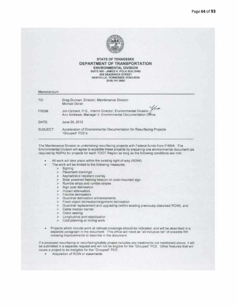
Page 64 of 93

Page 65 of 93

Page 66 of 93

Page 67 of 93

Page 68 of 93

Page 69 of 93
FUNDING (Federal vs. State) Currently the Department utilizes both federal (STP/NHS) and state funds to perform annual state route resurfacing projects. In the past this was not always the case. Up through the 2003 paving season (2003-2004 funding), all state route resurfacing projects were performed utilizing 100% state funds. Beginning in 2004 (2004-2005 funding), the Department began utilizing both federal and state funds for the resurfacing program. During the 2004 paving season, approximately 50% of resurfacing was funded with federal funds and 50% with state funds. Over the years, as funding allocations have increased, the percentages of the type of funding have also changed. As of the 2013 paving season, federal funding has increased to approximately 63% with the state funding having decreased to 37%. Originally federal funded projects required environmental permitting prior to letting, but over time, this requirement was changed to include all resurfacing projects (both federal and state funded). Also, only federally funded resurfacing projects required the upgrades of needed safety features in 2004. Currently, all state resurfacing projects must address needed safety feature upgrades (See next section on Safety Improvements/HSIP funds for details). Essentially, federal funds can be designated for resurfacing projects on state roadways which have an existing two-foot minimum paved shoulder (or curb and gutter section). Rumble strips (or rumble stripes) are required on all federally funded resurfacing projects with the exception of curb and gutter sections (see Table 4-3 on pages 4-93 through 4-95 of TDOT’s Roadway Design Guidelines for details). Also, upgrading of all guardrail terminals to meet the current federal safety guidelines are required (terminal placement only, no ROW/widening for terminal pads required). As stated above, the guardrail terminal upgrades can be paid for utilizing HSIP funds. Attached below is a memorandum dated April 5, 2004 which addresses the “Use of Federal Funds” for State Route resurfacing beginning in the 2004/2005 fiscal year.
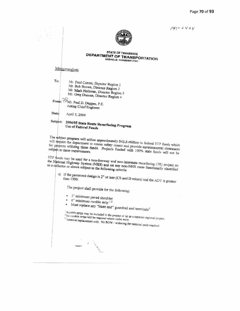
Page 70 of 93

Page 71 of 93

Page 72 of 93
LOW COST SAFETY IMPROVEMENTS / HSIP Funding
In August of 2005, the federal government enacted The Safe, Accountable, Flexible, Efficient Transportation Equity Act: A Legacy for Users (SAFETEA- LU). Within this legislation, the Highway Safety Improvement Program (HSIP) was initiated as a core Federal Aid program. The intent of this program is to significantly reduce the number of traffic-related fatalities and/or serious injuries incurred on all public roadways. This is to be accomplished through the utilization and implementation of low-cost safety improvement measures on the nation’s roadways.
Beginning in 2008, TDOT began the implementation of low-cost safety improvement measures on resurfacing projects with the monies supplied through HSIP funding. Originally, on resurfacing projects performed using federal funds (STP funds), the cost was absorbed through the STP project number. On resurfacing projects using only state funds, an additional federal project number was established to absorb the cost of these safety improvements. Currently, all resurfacing projects (minimum of $10,000 improvements) receive a federal project number (HSIP project number) to which to charge the cost of applicable safety improvements. If the improvements do not reach a minimum of $10,000, the cost will be absorbed under the normal resurfacing project number. To insure the Department conforms to the applicable use of these designated funds, a “Resurfacing Safety Checklist” was developed and implemented during the oreliminary survey & design process which each resurfacing project undergoes prior to development of construction plans. Over the years this checklist has evolved and improvements have been made to better achieve the desired goals of this program. Below is a sampling of items investigated during development of the construction plans to insure that sufficient safety improvements are being made:
1) Placement of rumble stripes or rumble strips on roadways with sufficient shoulder
width. 2) If shoulder width is less than two feet, can work be accomplished to upgrade to
shoulder width to two feet? 3) Upgrade guardrail terminals to meet NCHRP 350 guidelines. 4) Is signing adequate and visible? 5) For sections of roadway with known crash histories or in curve sections, can
centerline rumble stripes, raised pavement markers, snow-plowable markers, chevrons or etc. be installed to help delineate?
6) In curves, can superelevation be corrected or can skid resistance material be utilized? 7) Can roadside obstacles be moved, removed or protected? 8) Can pedestrian or cyclist safety be improved?

Page 73 of 93
9) Reshape ditches to obtain proper drainage. 10) Evaluation of existing sight distances. 11) Address railroad crossings within 220 ft. of the project limits. 12) Use of “Safety Edge” where it is applicable.
Railroad involvement, ADA ramp upgrades and bike plans are covered in greater detail in other sections of this document.
Attached at the end of this section is a copy of the current “Resurfacing Safety Review Checklist” currently utilized by the Department during the PS&E process. Also attached at the end of this section are copies of two memorandums addressing the “Repair and/or Installation of Curb Ramps on Resurfacing Projects” dated July 7, 2007 and “Response to Final Report 2006 Incorporating Safety into Resurfacing Projects (non-interstate)” dated February 23, 2007. In December of 2012 the Project Safety Office (PSO) requested the inclusion of asphalt in the Road Safety Audit (RSA) process. A December 3, 2012 memorandum is attached below addressing HSIP funds to include asphalt as a low-cost safety countermeasure.

Page 74 of 93

Page 75 of 93

Page 76 of 93

Page 77 of 93
Page 78 of 93

Page 79 of 93

Page 80 of 93

Page 81 of 93

Page 82 of 93

Page 83 of 93

Page 84 of 93
Page 85 of 93
RAILROAD INVOLVEMENT
Procedural steps have been adopted to address, as efficiently as possible, the development of railroad crossing improvement projects (including resurfacing projects) necessary for compliance with the federal Shanklin Law. In coordination with the TDOT ROW division, utilities section and program operations, a standard form has been developed by program operations for regions to obtain railroad project numbers for resurfacing projects that are within 200 feet of a railroad (see attached form in this section). It is requested that all regions use this form and process to obtain railroad project numbers. In order to effectively assist in the process of developing Federal-Aid funded resurfacing projects within each region that have railroad involvement, and to have sufficient time to properly coordinate these projects with the railroads and secure executed railroad contracts before the scheduled project advertisement dates, the following steps should be followed:
1) The Region should identify (as early as possible) the resurfacing projects that have railroad crossings within them or within 200 ft. of their project limits.
2) The Preliminary Survey & Engineering (PS&E) forms for any of those projects identified with railroad involvement always include 360-degree sweep of photos of the railroad grade crossing including the roadway Log Mile of the grade crossing (see attached handout of grade crossing photos).
3) When the Region Design Office requests the PCE (Programmatic Categorical Exclusion) Document for the Federal-Aid resurfacing project with railroad involvement that they ask the Environmental Office to include any required railroad upgrade work in that document as well, thereby eliminating the need for there to be two separate PCE Documents.
The most efficient method for performing the above requirements is for the region design office to first send the state railroad coordinator (ROW Division – Utilities Section) a title sheet with the grade crossing within 200 feet circled and identified with its DOT Identifier Number, which will normally be shown in the crossing photos. The state railroad coordinator will then e-mail that title sheet to Department’s Safety Planning & Travel Data Office requesting a quick review of the crossing warning devices for adequacy, and to make recommendations for any required upgrades and estimation of the costs associated with these recommendations. Once the information is received by the state railroad coordinator,

Page 86 of 93
it will be sent immediately to the Program Operations Office requesting the issuance of a PIN number and project number for the separate grade crossing upgrade work. Once the state railroad coordinator receives the PIN and project numbers for the grade crossing upgrade work, all information (including crossing upgrade recommendations) will be forwarded to the Region Design Office allowing them to have the Environmental Office include the railroad involvement information with the overall project PCE document. Also, a note shall be included stating that the active warning device upgrades or crossing surface upgrades are to be performed by the railroad. Any work recommended by the Department’s Safety Planning & Travel Data Office to replace advance railroad warning signs and pavement markings or railroad crossing crossbuck warning signs, or other passive warning signs and work to resurface up to both sides of a grade crossing within a resurfacing project are the responsibility of the State, and would be replaced and/or completed by the State Contractor as part of the resurfacing project (naturally included in the Project PCE Document). Once the above project development items have been completed, and PDF file copies of the project plans and PCE document are received by the state railroad coordinator’ office, then the state railroad coordinator’s office will take action on and perform all other coordinating with the railroad(s) from that point forward. NOTE: Photos are not required of highway bridges over railroads or for railroad bridges over highways, as there is no Shanklin Law review required or performed on these type crossings (the Shanklin Law only applies to at-grade crossings). However, the plans do need to indicate and/or specify whether a highway bridge over a railroad, within the limits of the project, is being repaired, repainted, etc., or whether it is just being cold planed with a new deck seal installed. Any repair work such as full or partial depth deck replacement, expansion joint repairs, concrete spall repairs, epoxy injection, etc., in spans over a railroads rights-of-way requires the Department to enter into a Railroad Agreement Process with the railroad involved. NOTE: On projects where a railroad bridge is over a highway (railroads refer to these type structures as an underpass), within the limits of the project, the plans shall show cold planing in the roadway approaches to and under the railroad underpass, so the existing vertical clearance between the lowest point of the railroad structure and the roadway surface in not diminished in any way.

Page 87 of 93
REQUEST FOR PROJECT ASSIGNMENT & FUNDING
HSIP TYPE OF FUNDING: RAILROAD CROSSING IMPROVEMENT
Phase: RAILROAD FORCE ACCOUNT Pin #:
Federal Project No:
State Project Number:
Estimate: $ (Provided by Utility Office)
ITEMS BELOW TO BE FILLED OUT BY REGION OFFICE: County: State Route: US Route:
Local Name: At: _ (Railroad Name)
Highway Log Mile:
Type of Work: See Recommendation Document (Provided by Utility Office)
CONSTRUCTION BY: RAILROAD FORCE ACCOUNT
Railroad Crossing Inventory #: SPECIAL INSTRUCTIONS:
*Action: Submit Funds To FHWA
Requested By: Date: Attached: Prog CE
Upgrade Recommendation Document from Safety, Planning & Travel Data Office Send To: Ronnie Porter
Program Operations Office Suite 600, James K Polk Bldg
CC: Headquarters Utility Office, Jim Byrd

Page 88 of 93
Shanklin Law Involvement: Grade Crossing Photos
For each at-grade railroad crossing within 200’ of any resurfacing project limits, it is required to take photos that clearly depict each of the following items:
Crossing Identification Number
Entire Crossing as a Whole
At Least One Photo from Each Approach
RXR Pavement Markings
All Grade Crossing Warning Signs and Plaques
All Grade Crossing Regulatory Signs and Plaques
Side Roads Parallel to Tracks within 100’ of Crossing
Speed Limit of Road and Side Roads within 100’
Any Sight Distance Issues and/or Sight Obstructions NOTE: Please label photos appropriately, especially when there are side roads and/or more than one crossing involved.

Page 89 of 93
Grade Crossing Photo Examples
Crossing Identification Number
Entire Crossing as a Whole (At Least 1 Photo for Each Approach)

Page 90 of 93
RXR Pavement Markings
All Grade Crossing Warning Signs and Plaques

Page 91 of 93
i*
v
Figure 88-1. Regulatory Signs andPlaques for Grade Crossings
eRt t
R3-ta Rt-2 Activated Slank-Ovt
R3-2a Activated61ank-Ovt
DO NOT
STOP ON
TRACKS R8-8
TRACKS OUT Of SERVICE
R 89
STOP HERE WHEN
FLASHING
RS.10
STOP
HERE
At:':N FLASHING
R8-t0a
STOP HERE ON
RED
A10·6
STOP HERE
RED
R10-6a
Rt5-4b
R15 1
RIS-4<:
9ioches
T
R15-2P
DO NOT
PASS AIS-5
II EXEMPTII R1$-3P
DO NOT PASS
STOPPED TRAIN
A IS-Sa
Rt5·4a
RIS-6
DO NOT
DRIVE ON TRACKS
HICH WAY HIGHWAY
R15-6a
R15 7
A1S..7a A15·8

Page 92 of 93
Side Roads Parallel to Tracks within 100' of Crossing

Page 93 of 93
Speed Limit of Road and Side Roads within 100’
Any Sight Distance Issues and/or Sight Obstructions