THE PROCESS OF MAKING 3D-VECTOR · PDF fileTHE PROCESS OF MAKING 3D-VECTOR SCENOGRAPH OF...
5
THE PROCESS OF MAKING 3D-VECTOR SCENOGRAPH OF ANCIENT BUILDING WITH LARGE QUANTITIES OF DATA Yixuan ZHU*, Zhiyong CHEN** Wuhan Technical University of Surveying and Mapping Department of Information Engineering [email protected] Wuhan, China KEY WORDS: Block, Layer, Orthograph, Scenograph. ABSTRACT This paper offers an introduction of the making process of 3D-vector scenograph of an ancient building with large quantities of data with the aid of AutoCAD, which display the effect of scenery drawings. The vital skills and technique involved are illustrated through the example of Pagoda of Thousands of Buddha in Chi Lin Nunnery in HongKong. Which was started in the year of 1996 and finished in 1999 with the concrete structure internal and wood external, imitating the style of buildings in Tang Dynasty. Thus, 3D-vector scenograph become available to users. 1 INTRODUCTION Ancient buildings, as the essence of ancient Chinese culture, characterized by its complex and antique shape, delicate structure, compact combination and graceful sculpture, is welcomed globally. Some ancient buildings made of wood endure long because of its solid structure. For example, the existent Nanchan Temple and Foguang Temple on Wutai Mountain in Shanxi Province of China can be traced back to Tang Dynasty. Nowadays, the building techniques have been constantly renovated due to the integration of both old and new ones. Before the birth of computer, the available drawings and internal structure drawings were all made by hand. The scenery effect of the building perceived by human eyes was demonstrated in the drawings made by building artist. The popularity of the technology of CAD provides sufficient hardware and software environment for the making of 3D scenery effect drawings of shape and internal structure drawings. It is with the aid of computer technology that the delicacy and meticulousness of ancient buildings have been represented accurately and perfectly, and that the abstract technology has been simplified. 2 THE MAKING PROCESS Collection of original data 6 Making of separate parts of the building 6 Combination of part structure drawings 6 Combination of the whole building 6 making of 3D scenograph. 2.1 Collection of original data There are four methods of collection required by different practical conditions. 2.1.1 On the practically measure. The original data of the example of Pagoda of Thousands of Buddha is obtained by measuring the actual parts of the building. 2.1.2 Making of 3D drawings based on plane figure. Under the condition that no processed actual part has been made, the 2d data can be transformed into 3d data according to the design drawings. 2.1.3 Obtaining 3D data of parts with complex surface by converting the results from PhotoModeler into AutoCAD. 2.1.4 Making of 3D according to designs directly in case of lacking plane figure 2.2 Making of drawings of separate parts of the building The establishment of 3D models starts from the individual part reasonably in response to the property of ancient buildings that the whole body is occluded compactly through rabbets and mortises of each single part. A closed and independent 3D drawings, its shape, direction, size total Figure 1 Yixuan, Zhu International Archives of Photogrammetry and Remote Sensing. Vol. XXXIII, Part B5. Amsterdam 2000. 914
Transcript of THE PROCESS OF MAKING 3D-VECTOR · PDF fileTHE PROCESS OF MAKING 3D-VECTOR SCENOGRAPH OF...
THE PROCESS OF MAKING 3D-VECTOR SCENOGRAPH OF ANCIENT BUILDINGWITH LARGE QUANTITIES OF DATA
Yixuan ZHU*, Zhiyong CHEN**Wuhan Technical University of Surveying and Mapping
Department of Information [email protected]
Wuhan, China
KEY WORDS: Block, Layer, Orthograph, Scenograph.
ABSTRACT
This paper offers an introduction of the making process of 3D-vector scenograph of an ancient building with large quantities ofdata with the aid of AutoCAD, which display the effect of scenery drawings. The vital skills and technique involved are illustratedthrough the example of Pagoda of Thousands of Buddha in Chi Lin Nunnery in HongKong. Which was started in the year of 1996and finished in 1999 with the concrete structure internal and wood external, imitating the style of buildings in Tang Dynasty. Thus,3D-vector scenograph become available to users.
1 INTRODUCTION
Ancient buildings, as the essence of ancient Chinese culture, characterized by its complex and antique shape, delicatestructure, compact combination and graceful sculpture, is welcomed globally. Some ancient buildings made of wood endurelong because of its solid structure. For example, the existent Nanchan Temple and Foguang Temple on Wutai Mountain inShanxi Province of China can be traced back to Tang Dynasty. Nowadays, the building techniques have been constantlyrenovated due to the integration of both old and new ones. Before the birth of computer, the available drawings and internalstructure drawings were all made by hand. The scenery effect of the building perceived by human eyes was demonstrated inthe drawings made by building artist. The popularity of the technology of CAD provides sufficient hardware and softwareenvironment for the making of 3D scenery effect drawings of shape and internal structure drawings. It is with the aid ofcomputer technology that the delicacy and meticulousness of ancient buildings have been represented accurately andperfectly, and that the abstract technology has been simplified.
2 THE MAKING PROCESS
Collection of original data 6 Making of separate parts of the building 6 Combination of part structure drawings 6 Combination ofthe whole building 6 making of 3D scenograph.
2.1 Collection of original data
There are four methods of collection required by different practical conditions.
2.1.1 On the practically measure. The original data of the example of Pagoda of Thousands of Buddha is obtained by measuringthe actual parts of the building.
2.1.2 Making of 3D drawings based on plane figure. Under the condition that no processed actual part has been made, the 2d datacan be transformed into 3d data according to the design drawings.
2.1.3 Obtaining 3D data of parts with complex surface by converting the results from PhotoModeler into AutoCAD.
2.1.4 Making of 3D according to designs directly in case of lacking plane figure
2.2 Making of drawings of separate parts of the building
The establishment of 3D models starts from the individual part reasonably inresponse to the property of ancient buildings that the whole body is occludedcompactly through rabbets and mortises of each single part.
A closed and independent 3D drawings, its shape, direction, size totalFigure 1
Yixuan, Zhu
International Archives of Photogrammetry and Remote Sensing. Vol. XXXIII, Part B5. Amsterdam 2000.914
consistent with its equivalent actual object reflect each model of the part. Such as Figure 1 is the 3D-drawing of Dou and Gong.
2.3 Combination of one floor
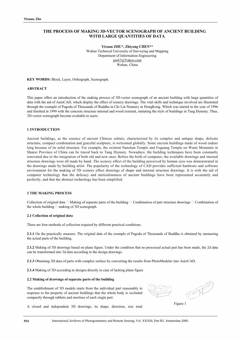
In view of the fact that the wood ancient building is combined through rabbets and mortises of many sub-parts, it is usually divideinto Columns, Dougong Layer, Roof frame, Eave Layer and Tile. The simulating process manipulated by AutoCAD must stick tothe principle of compact combination. Only in this way can the drawings reflect the exterior appearance and internal structuretruly. After the 3D drawings of each part have been made, computers begin the organization layer by layer. Figure 2 shows theorganization of part of the Dougong; Figure 3 shows the organization of the whole body of Dougong; Figure 4 shows theorganization of the floor 1.
2.4 Combination of the whole
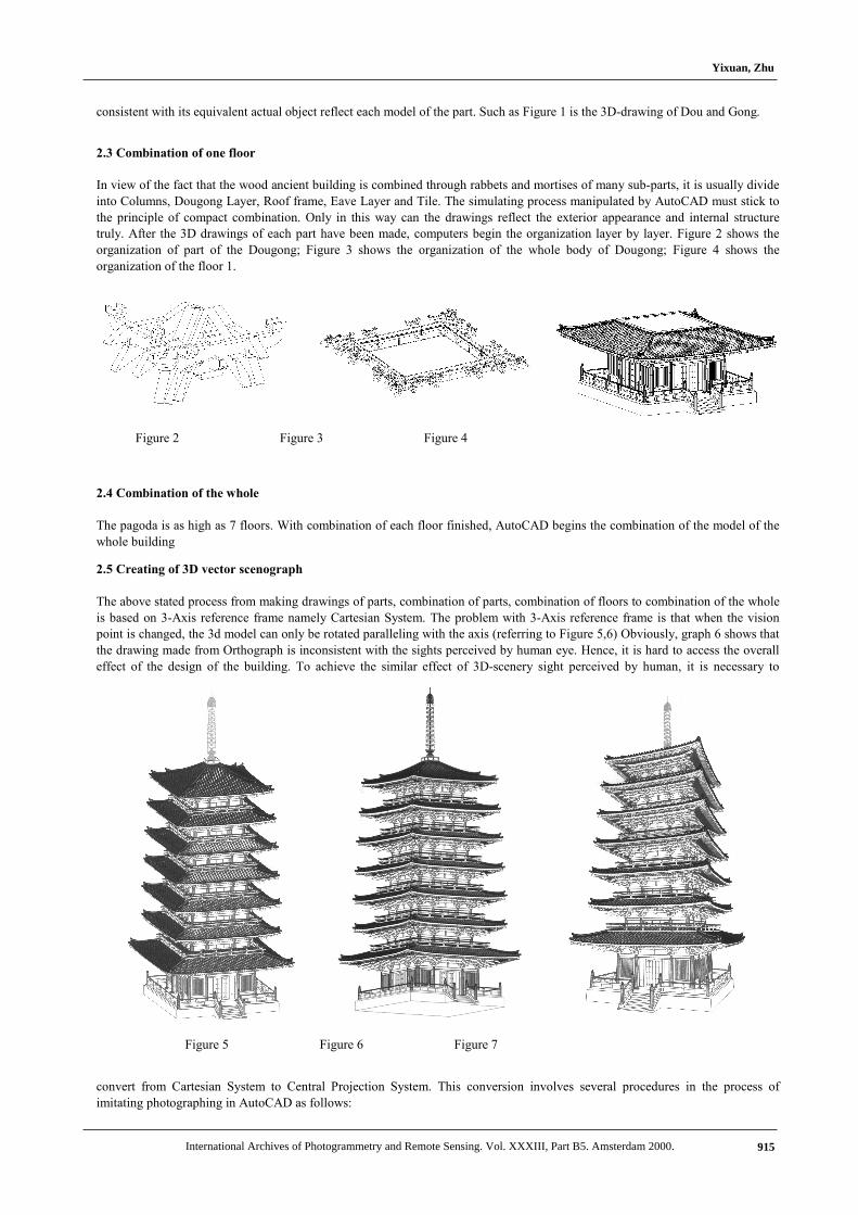
The pagoda is as high as 7 floors. With combination of each floor finished, AutoCAD begins the combination of the model of thewhole building
2.5 Creating of 3D vector scenograph
The above stated process from making drawings of parts, combination of parts, combination of floors to combination of the wholeis based on 3-Axis reference frame namely Cartesian System. The problem with 3-Axis reference frame is that when the visionpoint is changed, the 3d model can only be rotated paralleling with the axis (referring to Figure 5,6) Obviously, graph 6 shows thatthe drawing made from Orthograph is inconsistent with the sights perceived by human eye. Hence, it is hard to access the overalleffect of the design of the building. To achieve the similar effect of 3D-scenery sight perceived by human, it is necessary to
convert from Cartesian System to Central Projection System. This conversion involves several procedures in the process ofimitating photographing in AutoCAD as follows:
Figure 2 Figure 3 Figure 4
Figure 5 Figure 6 Figure 7
Yixuan, Zhu
International Archives of Photogrammetry and Remote Sensing. Vol. XXXIII, Part B5. Amsterdam 2000. 915
2.5.1 The choice of zoom
The choice of zoom depends on the practical requirements and it determines the view angle. The short zoom should be chosenwhen the model has to be observed within short distance through wide view angle. By contrast, the long zoom is preferred whenthe model is to be observed within farther distance through narrow view angle. Therefor, the short zoom is preferable to the longone when the graph is intended to display primarily the grander and height of the building, and vice verse.
2.5.2 Choice of camera distance
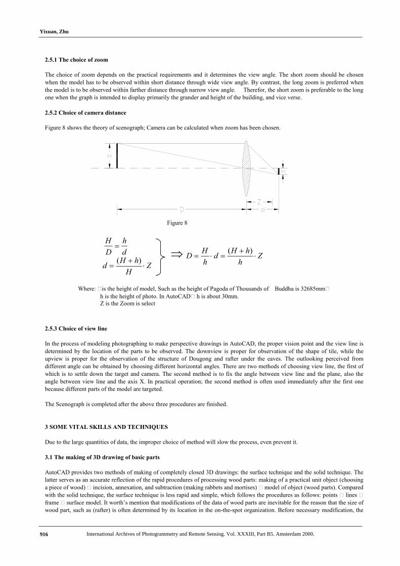
Figure 8 shows the theory of scenograph; Camera can be calculated when zoom has been chosen.
2.5.3 Choice of view line
In the process of modeling photographing to make perspective drawings in AutoCAD, the proper vision point and the view line isdetermined by the location of the parts to be observed. The downview is proper for observation of the shape of tile, while theupview is proper for the observation of the structure of Dougong and rafter under the eaves. The outlooking perceived fromdifferent angle can be obtained by choosing different horizontal angles. There are two methods of choosing view line, the first ofwhich is to settle down the target and camera. The second method is to fix the angle between view line and the plane, also theangle between view line and the axis X. In practical operation; the second method is often used immediately after the first onebecause different parts of the model are targeted.
The Scenograph is completed after the above three procedures are finished.
3 SOME VITAL SKILLS AND TECHNIQUES
Due to the large quantities of data, the improper choice of method will slow the process, even prevent it.
3.1 The making of 3D drawing of basic parts
AutoCAD provides two methods of making of completely closed 3D drawings: the surface technique and the solid technique. Thelatter serves as an accurate reflection of the rapid procedures of processing wood parts: making of a practical unit object (choosinga piece of wood) 6 incision, annexation, and subtraction (making rabbets and mortises) 6 model of object (wood parts). Comparedwith the solid technique, the surface technique is less rapid and simple, which follows the procedures as follows: points 6 lines 6frame 6 surface model. It worth’s mention that modifications of the data of wood parts are inevitable for the reason that the size ofwood part, such as (rafter) is often determined by its location in the on-the-spot organization. Before necessary modification, the
d
h
D
H!
ZH
hHd "
#!
)(Z
h
hHd
h
HD "
#!"!
)($
Where: 6is the height of model, Such as the height of Pagoda of Thousands of Buddha is 32685mm6h is the height of photo. In AutoCAD6 h is about 30mm.Z is the Zoom is select
Figure 8
Yixuan, Zhu
International Archives of Photogrammetry and Remote Sensing. Vol. XXXIII, Part B5. Amsterdam 2000.916
wood parts are anything than the final products. The technique of solid thus meets the demand of modifications more facilely.Despite the above advantages, the technique of solid is disadvantaged by the large quantities of data produced by the solid modelwith information about the internal structure. Thus, currently, the technique of solid is only applicable to organization of buildingsin a relatively small scale. For example, the total quantity of data of Pagoda of Thousands of Buddhas with approximately 9,980pieces of individual wood parts and 12,000 pieces of tile produced, by the solid technique is as many as 120Mb,ten times as thatproduced by the surface technique. It is impossible for the present PC technology to deal with that.
In conclusion, the solid technique is employed only to a small number of parts with large quantities of data in order to meet thedemand of modification such as rafter. The other parts are finished with the help of the surface technique.
3.2 The technique of block and layer
The primary techniques employed in organization are the technique of block and layer.
The technique of block requires that each part in the graph of organization be in the form of a whole body, that is, a block. A blockrefers to not only a single piece of part but also a compounded part, such as the larger parts of the door and the window consistingof smaller sub-parts. Figure 3 shows Dougong Layer of the floor 1, which belongs to a larger block of the whole floor 1 shown ingraph 4. The concept of block facilitated the separate operation of move, copy, rotation and mirroring.
The technique of layer manipulates each layer separately by putting different parts into different layers. Some merits lies in the factthat layers set with distinct colors facilitates differentiation so that some layers can be closed or freeze in certain conditions.
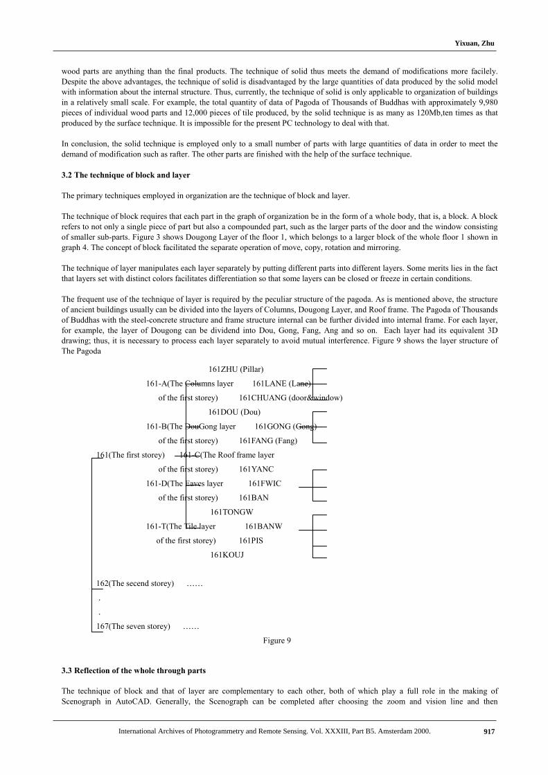
The frequent use of the technique of layer is required by the peculiar structure of the pagoda. As is mentioned above, the structureof ancient buildings usually can be divided into the layers of Columns, Dougong Layer, and Roof frame. The Pagoda of Thousandsof Buddhas with the steel-concrete structure and frame structure internal can be further divided into internal frame. For each layer,for example, the layer of Dougong can be dividend into Dou, Gong, Fang, Ang and so on. Each layer had its equivalent 3Ddrawing; thus, it is necessary to process each layer separately to avoid mutual interference. Figure 9 shows the layer structure ofThe Pagoda
3.3 Reflection of the whole through parts
The technique of block and that of layer are complementary to each other, both of which play a full role in the making ofScenograph in AutoCAD. Generally, the Scenograph can be completed after choosing the zoom and vision line and then
161ZHU (Pillar)
161-A(The Columns layer 161LANE (Lane)
of the first storey) 161CHUANG (door&window)
161DOU (Dou)
161-B(The DouGong layer 161GONG (Gong)
of the first storey) 161FANG (Fang)
161(The first storey) 161-C(The Roof frame layer
of the first storey) 161YANC
161-D(The Eaves layer 161FWIC
of the first storey) 161BAN
161TONGW
161-T(The Tile layer 161BANW
of the first storey) 161PIS
161KOUJ
162(The secend storey) ……
.
.
167(The seven storey) ……
Figure 9
Yixuan, Zhu
International Archives of Photogrammetry and Remote Sensing. Vol. XXXIII, Part B5. Amsterdam 2000. 917
calculating the distance. However, the inputs parameters designed according to the calculated values are inadequate to producesatisfactory results. The process of producing of satisfactory Scenograph is a processrequiring gradual regulations.
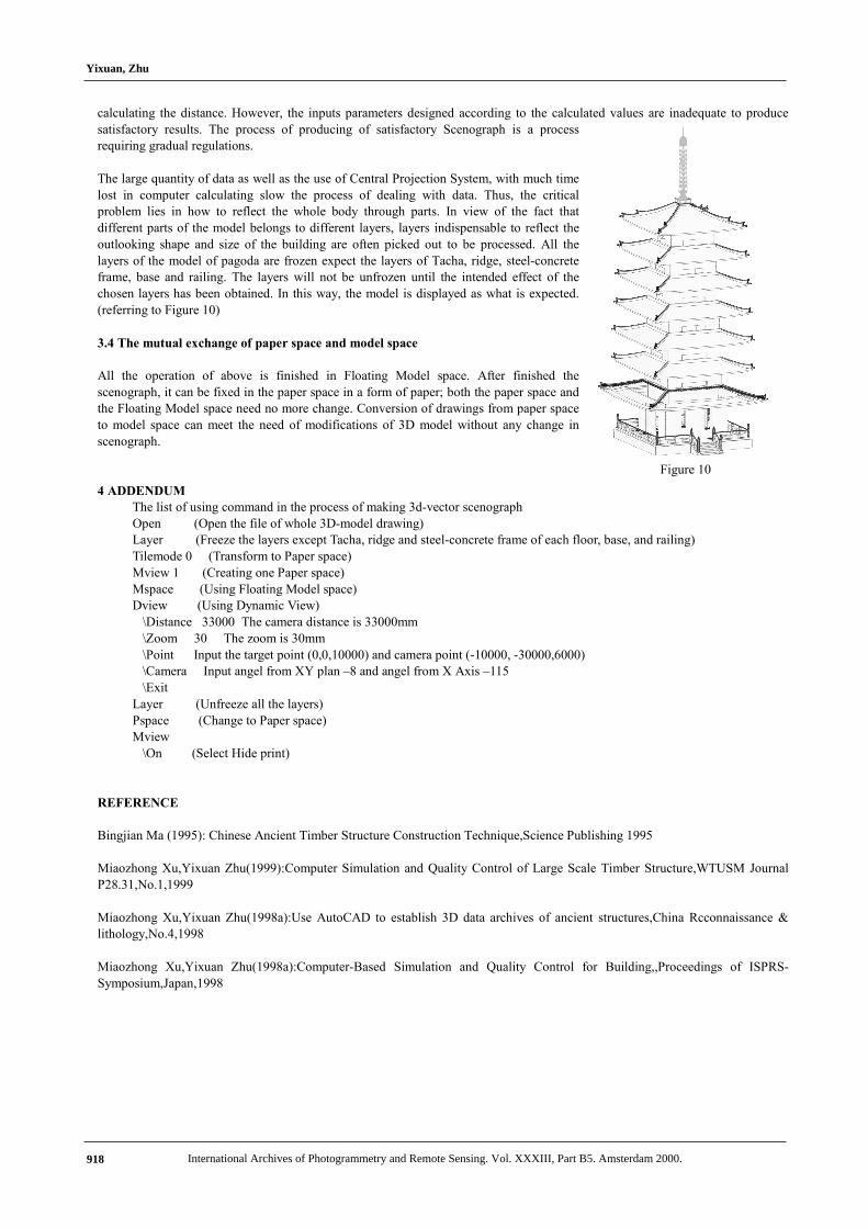
The large quantity of data as well as the use of Central Projection System, with much timelost in computer calculating slow the process of dealing with data. Thus, the criticalproblem lies in how to reflect the whole body through parts. In view of the fact thatdifferent parts of the model belongs to different layers, layers indispensable to reflect theoutlooking shape and size of the building are often picked out to be processed. All thelayers of the model of pagoda are frozen expect the layers of Tacha, ridge, steel-concreteframe, base and railing. The layers will not be unfrozen until the intended effect of thechosen layers has been obtained. In this way, the model is displayed as what is expected.(referring to Figure 10)
3.4 The mutual exchange of paper space and model space
All the operation of above is finished in Floating Model space. After finished thescenograph, it can be fixed in the paper space in a form of paper; both the paper space andthe Floating Model space need no more change. Conversion of drawings from paper spaceto model space can meet the need of modifications of 3D model without any change inscenograph.
4 ADDENDUMThe list of using command in the process of making 3d-vector scenographOpen (Open the file of whole 3D-model drawing)Layer (Freeze the layers except Tacha, ridge and steel-concrete frame of each floor, base, and railing)Tilemode 0 (Transform to Paper space)Mview 1 (Creating one Paper space)Mspace (Using Floating Model space)Dview (Using Dynamic View) \Distance 33000 The camera distance is 33000mm \Zoom 30 The zoom is 30mm \Point Input the target point (0,0,10000) and camera point (-10000, -30000,6000) \Camera Input angel from XY plan –8 and angel from X Axis –115 \ExitLayer (Unfreeze all the layers)Pspace (Change to Paper space)Mview \On (Select Hide print)
REFERENCE
Bingjian Ma (1995): Chinese Ancient Timber Structure Construction Technique,Science Publishing 1995
Miaozhong Xu,Yixuan Zhu(1999):Computer Simulation and Quality Control of Large Scale Timber Structure,WTUSM JournalP28.31,No.1,1999
Miaozhong Xu,Yixuan Zhu(1998a):Use AutoCAD to establish 3D data archives of ancient structures,China Rcconnaissance &lithology,No.4,1998
Miaozhong Xu,Yixuan Zhu(1998a):Computer-Based Simulation and Quality Control for Building,,Proceedings of ISPRS-Symposium,Japan,1998
Figure 10
Yixuan, Zhu
International Archives of Photogrammetry and Remote Sensing. Vol. XXXIII, Part B5. Amsterdam 2000.918