The Most Common Errors in Wind Design & How to Avoid...
102
September 19, 2014 Emily Guglielmo, S.E. Martin/Martin, Inc. The Most Common Errors in Wind Design & How to Avoid Them
Transcript of The Most Common Errors in Wind Design & How to Avoid...

September 19, 2014
Emily Guglielmo, S.E.Martin/Martin, Inc.
The Most Common Errors in Wind Design & How to Avoid Them

Enclosure Classification (26.2):
• Enclosed Building: A building that does not comply with the requirements for open or partially enclosed buildings.
• Open Building: A building having each wall at least 80 percent open.• Partially Enclosed Building: A building that complies with both of the
following conditions:1. The total area of openings in a wall that receives positive external pressure exceeds
the sum of the areas of openings in the balance of the building envelope (walls and roof) by more than 10 percent.
2. The total area of openings in a wall that receives positive external pressure exceeds 4ft2 or 1% of area of that wall, whichever is smaller, and the percentage of openings in the balance of the building envelope does not exceed 20%.
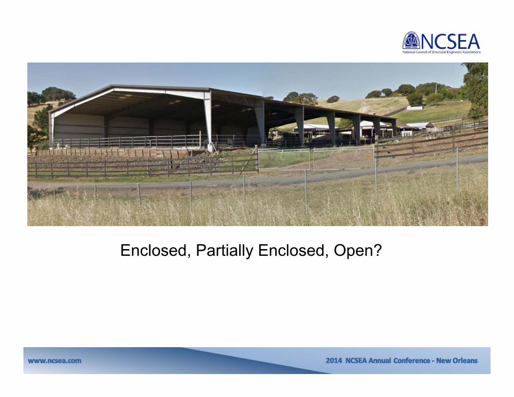
Enclosed, Partially Enclosed, Open?

Open Building: A building having each wall at least 80 percent open.

Partially Enclosed Building: A building that complies with both of the conditions:1. The total openings in a wall exceeds the sum of the areas of openings in the balance of the building
envelope by >10%.
2. The total area of openings in a wall that receives positive external pressure exceeds 4ft2 or 1% of area of that wall, and the percentage of openings in the balance of the building envelope ≤ 20%.

Enclosed Building: A building that does not comply with the requirements for open or partially enclosed buildings.
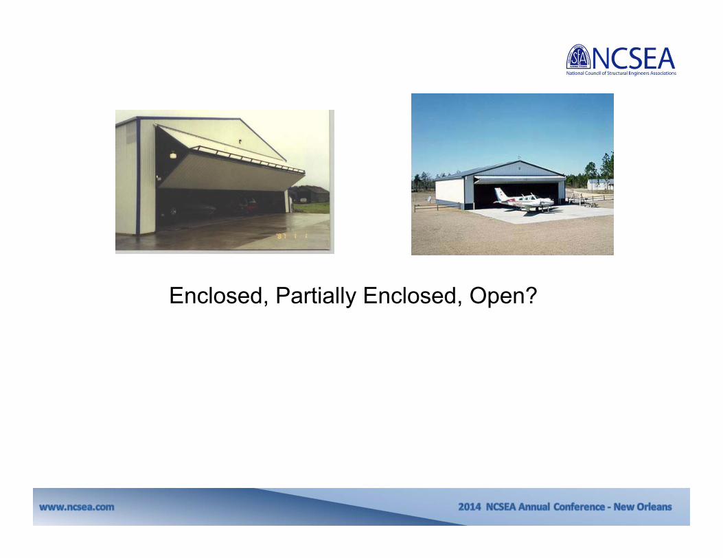
Enclosed, Partially Enclosed, Open?

Enclosed, Partially Enclosed, Open?
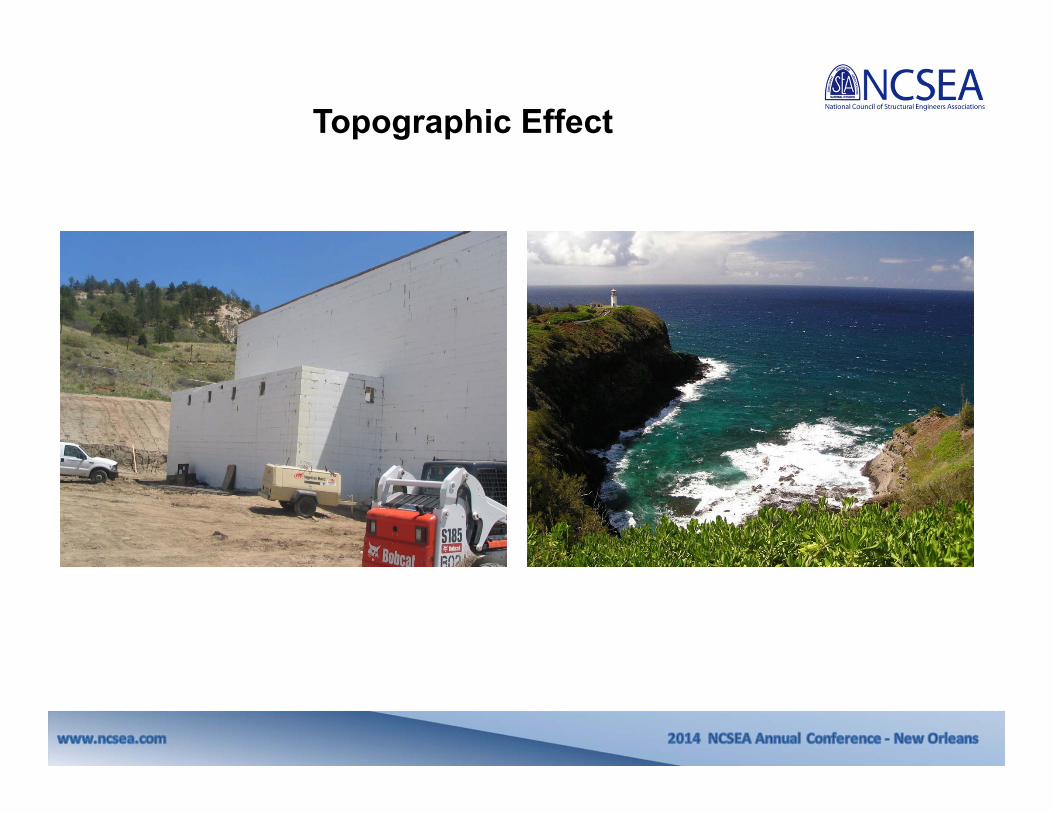
Topographic Effect

Topographic Effect• Local abrupt topography affects wind near the ground.
– “Speed-up effect” due to fluid mechanics (incompressible flow/ incompatibility)
• Wind speed depends on shape of hill, location of building, and height above ground.
• Must meet all the criteria of ASCE 6.5.7.1. Many times the topography does not qualify.

Torsion

ASCE 7-10
13
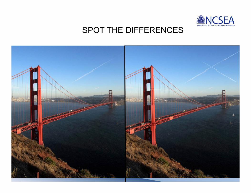
SPOT THE DIFFERENCES

14
SPOT THE DIFFERENCES

ASCE 7-05 ASCE 7-10
SPOT THE DIFFERENCES

ASCE 7-05 ASCE 7-10
.
.
.
.
.
.
.
.
.
.
.
.
.
.
.
.
.
.
SPOT THE DIFFERENCES

17
ASCE 7-05 ASCE 7-10
SPOT THE DIFFERENCES

ASCE 7-05 ASCE 7-10
SPOT THE DIFFERENCES
ASCE 7-05 ASCE 7-10
SPOT THE DIFFERENCES

20
ASCE 7-05 ASCE 7-10
SPOT THE DIFFERENCES
21
ASCE 7-05 ASCE 7-10
SPOT THE DIFFERENCES
22
ASCE 7-05 ASCE 7-10
SPOT THE DIFFERENCES

Reorganization
The wind load provisions of ASCE 7-05 (Chapter 6) have been reorganized into 6 Chapters in ASCE 7-10.
ASCE 7-05: ASCE 7-10:

• CHAPTER 26:Wind Loads: General Requirements• CHAPTER 27:Wind Loads On Buildings—MWFRS (Directional Procedure)• CHAPTER 28:Wind Loads On Buildings—MWFRS (Envelope Procedure)• CHAPTER 29:Wind Loads On Other Structures And Building
Appurtenances— MWFRS• CHAPTER 30:Wind Loads – Components And Cladding (C&C)• CHAPTER 31:Wind Tunnel Procedure
Reorganization

25
ADVANTAGES:
• Keeps section numbering smaller…. 6.4.2.1.1 now 28.6.4
• Locates major subject areas as distinct chapters.
• Orders the provisions in a logical sequence.
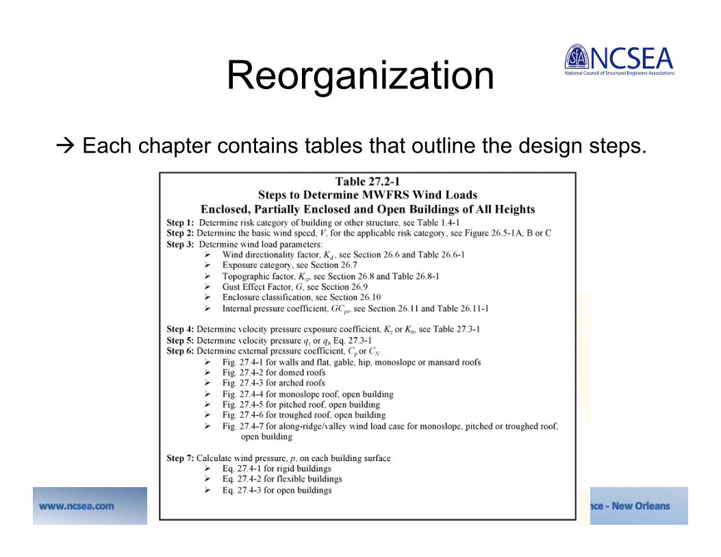
Reorganization Each chapter contains tables that outline the design steps.

27
Hurricane Zone Changes
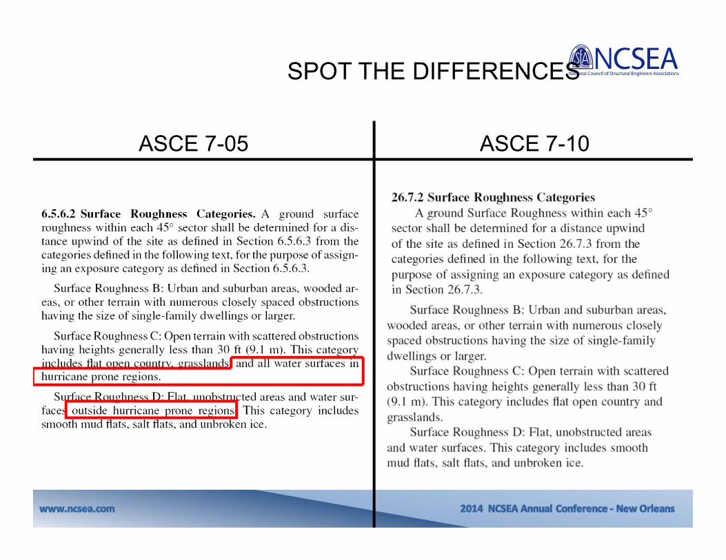
•New Hurricane Simulation Model– Generally lower design wind speeds.
•Reintroduction of Exposure D in hurricane regions.– Research shows that the roughness of ocean does not
continue to increase with increasing wind speed and Exposure D is valid.
•New windborne debris region results in less areas subject to windborne debris requirements.

Chapter 26: General Requirements
Section 26.5: Basic Wind Speeds
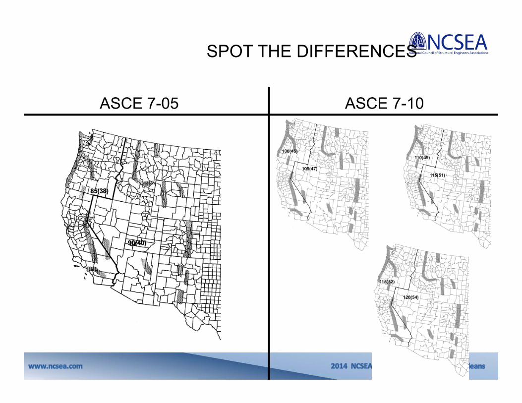
New wind speed maps with 2 major changes:1. Maps provide wind speeds at strength design
level.2. Maps are provided for different Risk
Categories instead of a single map with importance factors to be applied.

Be careful during transition to ASCE 7-10 with respect to wind loads (strength) and use of new/ old load combinations!
Chapter 26: General Requirements

30
ASCE 7-05:(1) BASICWIND SPEEDMAP

31
Occupancy/RiskCategory I
Occupancy/ RiskCategory II
Occupancy/ RiskCategory III, IV
ASCE 7-10: (3) BASIC WIND SPEED MAPS
300-year return period 700-year return period 1700-year return period
ASCE 7-05 I=0.87 or 0.77 ASCE 7-05 I=1.0 ASCE 7-05 I=1.15

COMPARATIVE WIND PRESSURES FOR SAN FRANCISCO
Chapter 26: General Requirements
33
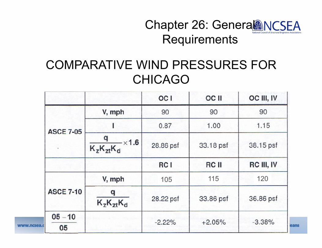
COMPARATIVE WIND PRESSURES FOR CHICAGO
105 115 120
Chapter 26: General Requirements

34
Chapter 26: General Requirements
Question:Resolution of the wind speed maps that are displayed in ASCE 7 are not sufficient to determine a site specific wind speed. There are no reference city or town locations on the ASCE 7 maps and while county boundaries are shown, the resolution is affected when the maps are expanded large enough to distinguish the boundaries and approximate the city locations.
Answer: ATC Webpagehttp://www.atcouncil.org/windspeed/

Chapter 26: General Requirements

Chapter 26: General Requirements

Question:If I have a product manufacturer’s evaluation report based on the unfactored wind speeds from ASCE 7-05 (or earlier), how can I correlate to ASCE 7-10 values?Answer:Similar to the wind speed map changes from fastest-mile to 3-second gust, the transition to strength level design maps will take some time and adjustment. To ease transition, a table is provided in the Commentary to ASCE 7-10.
Chapter 26: General Requirements

38
Question:Part of the map are listed as a “Special Wind Region” on the Basic Wind Speed Maps. How do I determine my wind pressures?Answer:Similar to current practice, the building department will have to develop a basic wind speed for their jurisdiction. However, they will now need to develop 3 winds speeds, dependent on risk category and take into account the change to strength level design forces for wind.
Chapter 26: General Requirements

ASCE 7-05 Wind Loads
Method 1:
Simplified ProcedureSection 6.4
Method 2:
Analytical ProcedureSection 6.5
Method 3: Wind Tunnel
ProcedureSection 6.6
MWFRS
6.4.2.1
Enclosed/Partially
Enclosed6.5.12
Open
6.5.13
Solid Walls/ Signs6.5.14
C&C
6.4.2.2
Other Structures
6.5.15
MWFRS
6.5.12.2
Buildings of All
Heights
6.5.12.2.1
Low-Rise Buildings
(h<60 feet)
6.5.12.2.2
Flexible Buildings
6.5.12.2.3
Parapets
6.5.12.2.4
C&C
6.5.12.4
Low-Rise Buildings h<60 feet
6.5.12.4.1
H> 60 feet
6.5.12.4.2
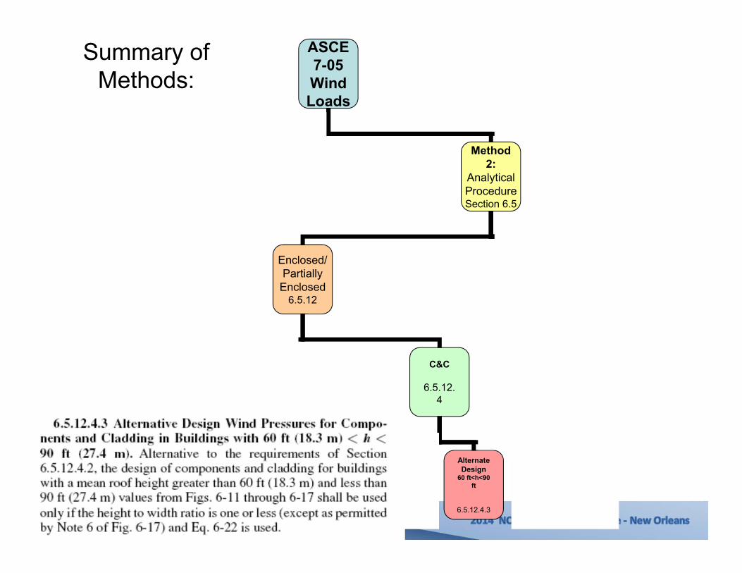
Alternate Design
60 ft<h<90 ft
6.5.12.4.3
Parapets
6.5.12.4.4
MWFRS
6.5.13.2
C&C
6.5.13.3
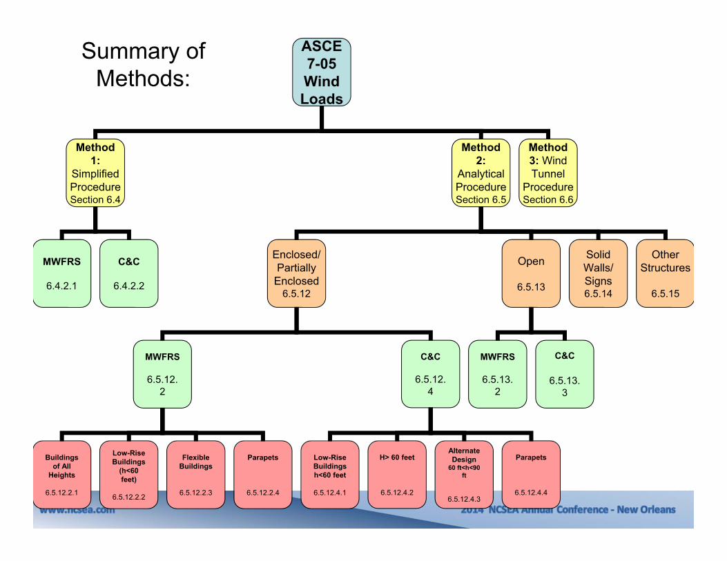
Summary of Methods:

40
ASCE 7-05 Wind Loads
Method 1:
Simplified ProcedureSection 6.4
Method 2:
Analytical ProcedureSection 6.5
Method 3: Wind Tunnel
ProcedureSection 6.6
MWFRS
6.4.2.1
Enclosed/Partially
Enclosed6.5.12
Open
6.5.13
Solid Walls/ Signs6.5.14
C&C
6.4.2.2
Other Structures
6.5.15
MWFRS
6.5.12.2
Buildings of All
Heights
6.5.12.2.1
Low-Rise Buildings
(h<60 feet)
6.5.12.2.2
Flexible Buildings
6.5.12.2.3
Parapets
6.5.12.2.4
C&C
6.5.12.4
Low-Rise Buildings h<60 feet
6.5.12.4.1
H> 60 feet
6.5.12.4.2
Alternate Design
60 ft<h<90 ft
6.5.12.4.3
Parapets
6.5.12.4.4
MWFRS
6.5.13.2
C&C
6.5.13.3
Summary of Methods:

41
ASCE 7-05 Wind Loads
Method 1:
Simplified ProcedureSection 6.4
Method 2:
Analytical ProcedureSection 6.5
Method 3: Wind Tunnel
ProcedureSection 6.6
MWFRS
6.4.2.1
Enclosed/Partially
Enclosed6.5.12
Open
6.5.13
Solid Walls/ Signs6.5.14
C&C
6.4.2.2
Other Structures
6.5.15
MWFRS
6.5.12.2
Buildings of All
Heights
6.5.12.2.1
Low-Rise Buildings
(h<60 feet)
6.5.12.2.2
Flexible Buildings
6.5.12.2.3
Parapets
6.5.12.2.4
C&C
6.5.12.4
Low-Rise Buildings h<60 feet
6.5.12.4.1
H> 60 feet
6.5.12.4.2
Alternate Design
60 ft<h<90 ft
6.5.12.4.3
Parapets
6.5.12.4.4
MWFRS
6.5.13.2
C&C
6.5.13.3
Summary of Methods:

43
ASCE 7-05 Wind Loads
Method 1:
Simplified ProcedureSection 6.4
Method 2:
Analytical ProcedureSection 6.5
Method 3: Wind Tunnel
ProcedureSection 6.6
MWFRS
6.4.2.1
Enclosed/Partially
Enclosed6.5.12
Open
6.5.13
Solid Walls/ Signs6.5.14
C&C
6.4.2.2
Other Structures
6.5.15
MWFRS
6.5.12.2
Buildings of All
Heights
6.5.12.2.1
Low-Rise Buildings
(h<60 feet)
6.5.12.2.2
Flexible Buildings
6.5.12.2.3
Parapets
6.5.12.2.4
C&C
6.5.12.4
Low-Rise Buildings h<60 feet
6.5.12.4.1
H> 60 feet
6.5.12.4.2
Alternate Design
60 ft<h<90 ft
6.5.12.4.3
Parapets
6.5.12.4.4
MWFRS
6.5.13.2
C&C
6.5.13.3
Summary of Methods:

44
ASCE 7-05 Wind Loads
Method 1:
Simplified ProcedureSection 6.4
Method 2:
Analytical ProcedureSection 6.5
Method 3: Wind Tunnel
ProcedureSection 6.6
MWFRS
6.4.2.1
Enclosed/Partially
Enclosed6.5.12
Open
6.5.13
Solid Walls/ Signs6.5.14
C&C
6.4.2.2
Other Structures
6.5.15
MWFRS
6.5.12.2
Buildings of All
Heights
6.5.12.2.1
Low-Rise Buildings
(h<60 feet)
6.5.12.2.2
Flexible Buildings
6.5.12.2.3
Parapets
6.5.12.2.4
C&C
6.5.12.4
Low-Rise Buildings h<60 feet
6.5.12.4.1
H> 60 feet
6.5.12.4.2
Alternate Design
60 ft<h<90 ft
6.5.12.4.3
Parapets
6.5.12.4.4
MWFRS
6.5.13.2
C&C
6.5.13.3
Summary of Methods:
Directional Approach
45
ASCE 7-05 Wind Loads
Method 1:
Simplified ProcedureSection 6.4
Method 2:
Analytical ProcedureSection 6.5
Method 3: Wind Tunnel
ProcedureSection 6.6
MWFRS
6.4.2.1
Enclosed/Partially
Enclosed6.5.12
Open
6.5.13
Solid Walls/ Signs6.5.14
C&C
6.4.2.2
Other Structures
6.5.15
MWFRS
6.5.12.2
Buildings of All
Heights
6.5.12.2.1
Low-Rise Buildings
(h<60 feet)
6.5.12.2.2
Flexible Buildings
6.5.12.2.3
Parapets
6.5.12.2.4
C&C
6.5.12.4
Low-Rise Buildings h<60 feet
6.5.12.4.1
H> 60 feet
6.5.12.4.2
Alternate Design
60 ft<h<90 ft
6.5.12.4.3
Parapets
6.5.12.4.4
MWFRS
6.5.13.2
C&C
6.5.13.3
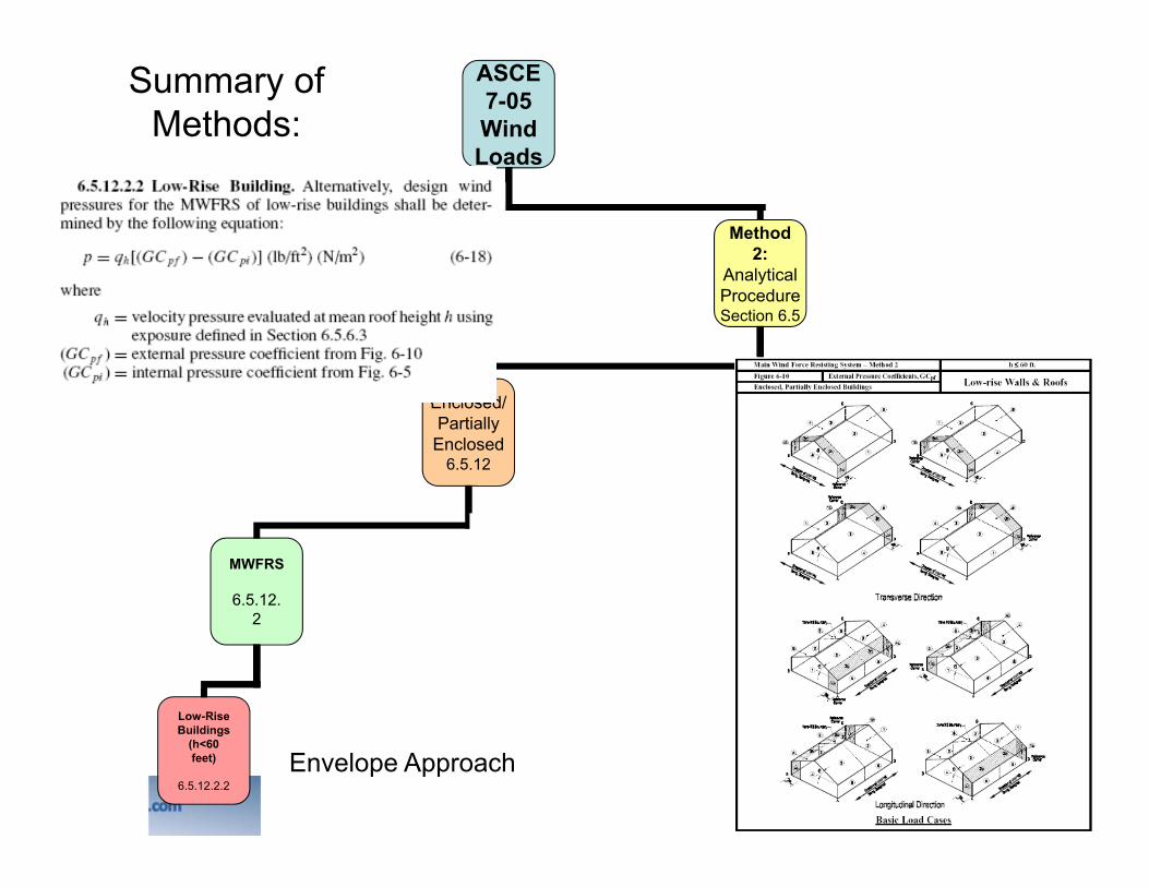
Summary of Methods:
Envelope Approach
46
ASCE 7-05 Wind Loads
Method 1:
Simplified ProcedureSection 6.4
Method 2:
Analytical ProcedureSection 6.5
Method 3: Wind Tunnel
ProcedureSection 6.6
MWFRS
6.4.2.1
Enclosed/Partially
Enclosed6.5.12
Open
6.5.13
Solid Walls/ Signs6.5.14
C&C
6.4.2.2
Other Structures
6.5.15
MWFRS
6.5.12.2
Buildings of All
Heights
6.5.12.2.1
Low-Rise Buildings
(h<60 feet)
6.5.12.2.2
Flexible Buildings
6.5.12.2.3
Parapets
6.5.12.2.4
C&C
6.5.12.4
Low-Rise Buildings h<60 feet
6.5.12.4.1
H> 60 feet
6.5.12.4.2
Alternate Design
60 ft<h<90 ft
6.5.12.4.3
Parapets
6.5.12.4.4
MWFRS
6.5.13.2
C&C
6.5.13.3
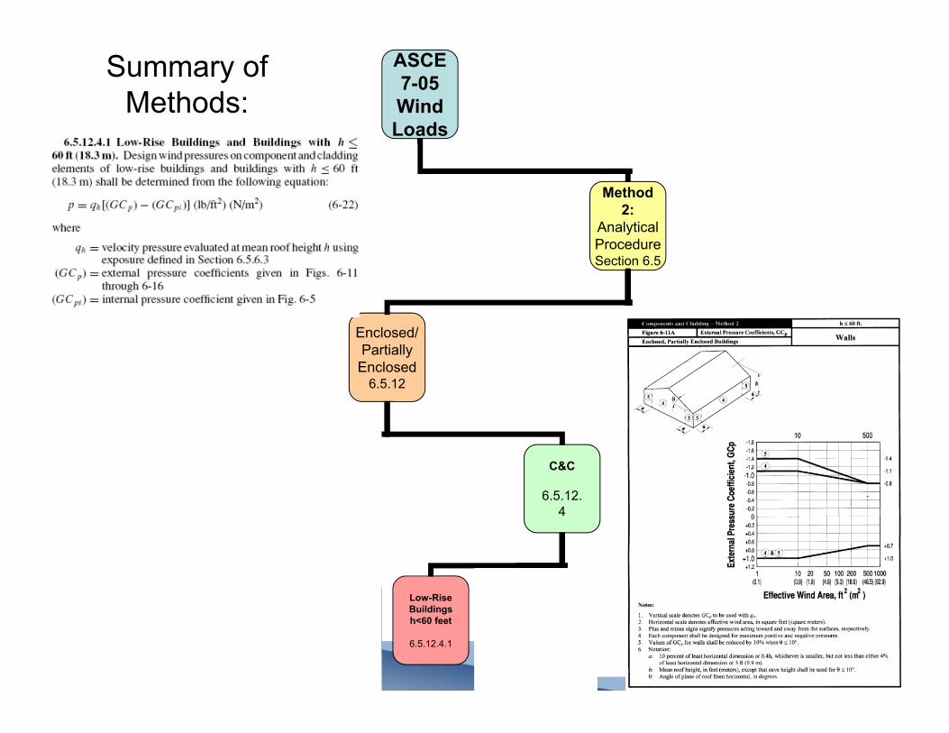
Summary of Methods:

ASCE 7-05 Wind Loads
Method 1:
Simplified ProcedureSection 6.4
Method 2:
Analytical ProcedureSection 6.5
Method 3: Wind Tunnel
ProcedureSection 6.6
MWFRS
6.4.2.1
Enclosed/Partially
Enclosed6.5.12
Open
6.5.13
Solid Walls/ Signs6.5.14
C&C
6.4.2.2
Other Structures
6.5.15
MWFRS
6.5.12.2
Buildings of All
Heights
6.5.12.2.1
Low-Rise Buildings
(h<60 feet)
6.5.12.2.2
Flexible Buildings
6.5.12.2.3
Parapets
6.5.12.2.4
C&C
6.5.12.4
Low-Rise Buildings h<60 feet
6.5.12.4.1
H> 60 feet
6.5.12.4.2
Alternate Design
60 ft<h<90 ft
6.5.12.4.3
Parapets
6.5.12.4.4
MWFRS
6.5.13.2
C&C
6.5.13.3
Summary of Methods:

50
ASCE 7-10Wind Loads
Chapter 27:
MWFRS
Directional Procedure
Chapter 28:
MWFRS
Envelope Procedure
Chapter 29:
MWFRS
Other Structure/ Building
Appurtenances
Part 1:
Enclosed, Partially
Enclosed, Open
Buildings All Heights
Part 1:
Enclosed and Partially
Enclosed Low-Rise Buildings
Part 2:
Enclosed Simple
Diaphragm Low- Rise Buildings
Part 2:
Enclosed Simple
Diaphragm Buildings
With h ≤160 ft
Chapter 30:
C&C
Part 1:
Low-Rise Buildings
Part 2:
Low-Rise Buildings
(Simplified)
Part 3:
Buildings with h>60 ft
Part 4:
Buildings with h≤160 ft (Simplified)
Part 5:
Open Buildings
Part 6:
Building Appurtenances, Rooftop Structures, Equipment
Chapter 31:
Wind Tunnel
Procedure
Summary of Methods:

51

52

53

54

55

56

57
•NO SUBSTANTIATIVE CHANGES
•NEW METHODS INTRODUCED
•LARGER CHANGES/ ADDITIONS

58
ASCE 7-05
ASCE 7-10
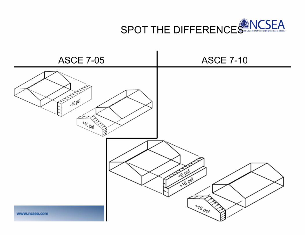
CHANGES TO MINIMUM DESIGN WIND LOADS
Sections 27.4.7, 28.4.4, 28.6.4

59
CHANGES TO MINIMUM DESIGN WIND LOADS
Sample Problem:Exposure BL=B=60 feethwall=8 feetRoof angle=10 degrees
hwall=8 feet
60
CHANGES TO MINIMUM DESIGN WIND LOADS
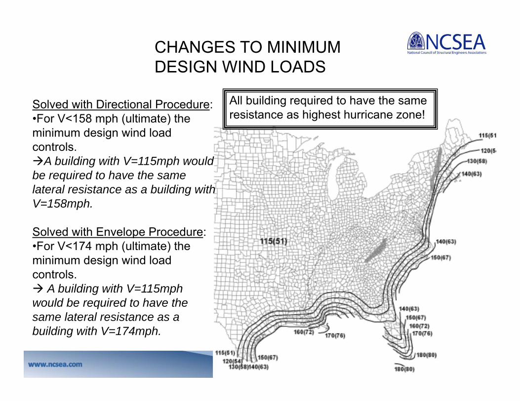
Solved with Directional Procedure:•For V<158 mph (ultimate) the minimum design wind load controls.A building with V=115mph would be required to have the same lateral resistance as a building with V=158mph.
Solved with Envelope Procedure:•For V<174 mph (ultimate) the minimum design wind load controls. A building with V=115mph would be required to have the same lateral resistance as a building with V=174mph.
All building required to have the sameresistance as highest hurricane zone!
61
CHANGES TO MINIMUM DESIGN WIND LOADS
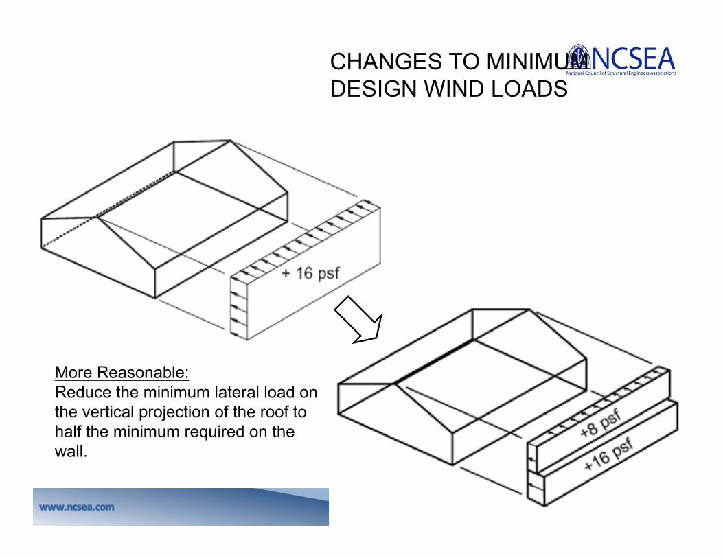
More Reasonable:Reduce the minimum lateral load on the vertical projection of the roof to half the minimum required on the wall.

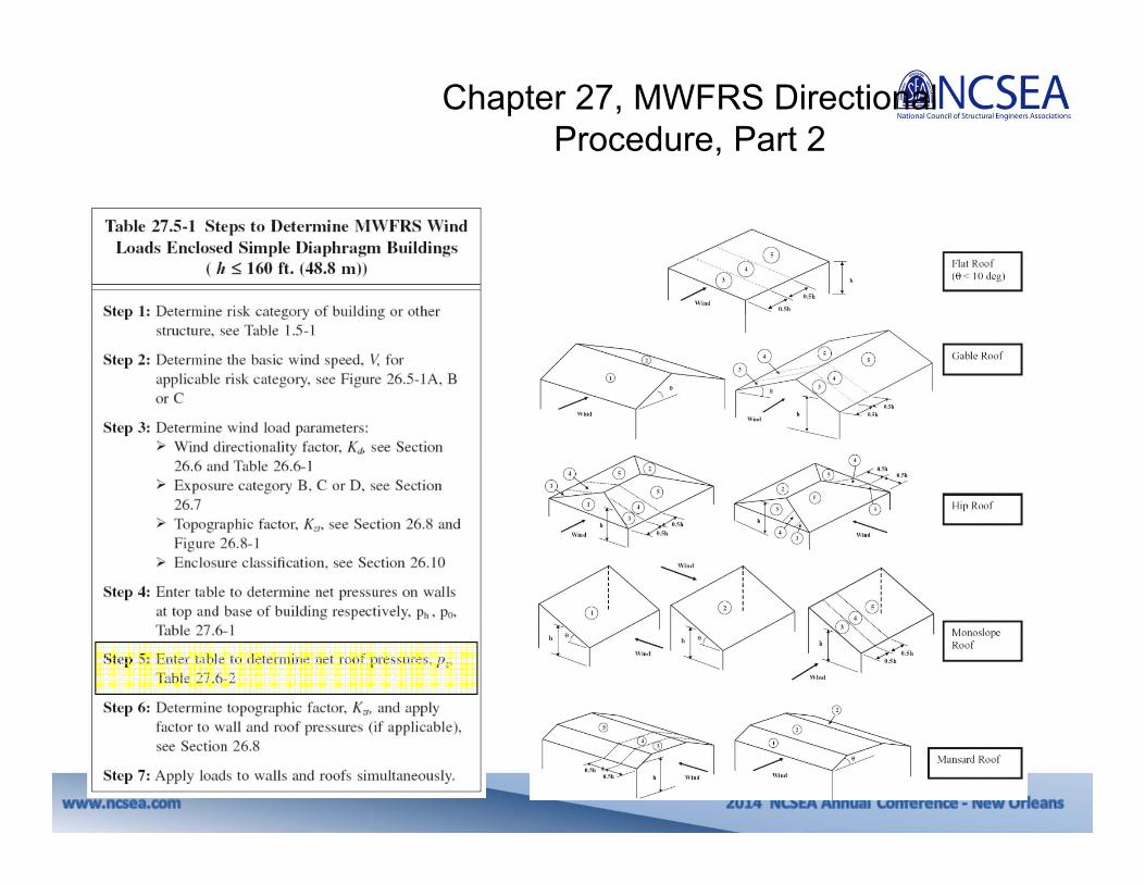
Chapter 27, MWFRS Directional Procedure, Part 2

63
UBC 1976 Wind Load Calculations
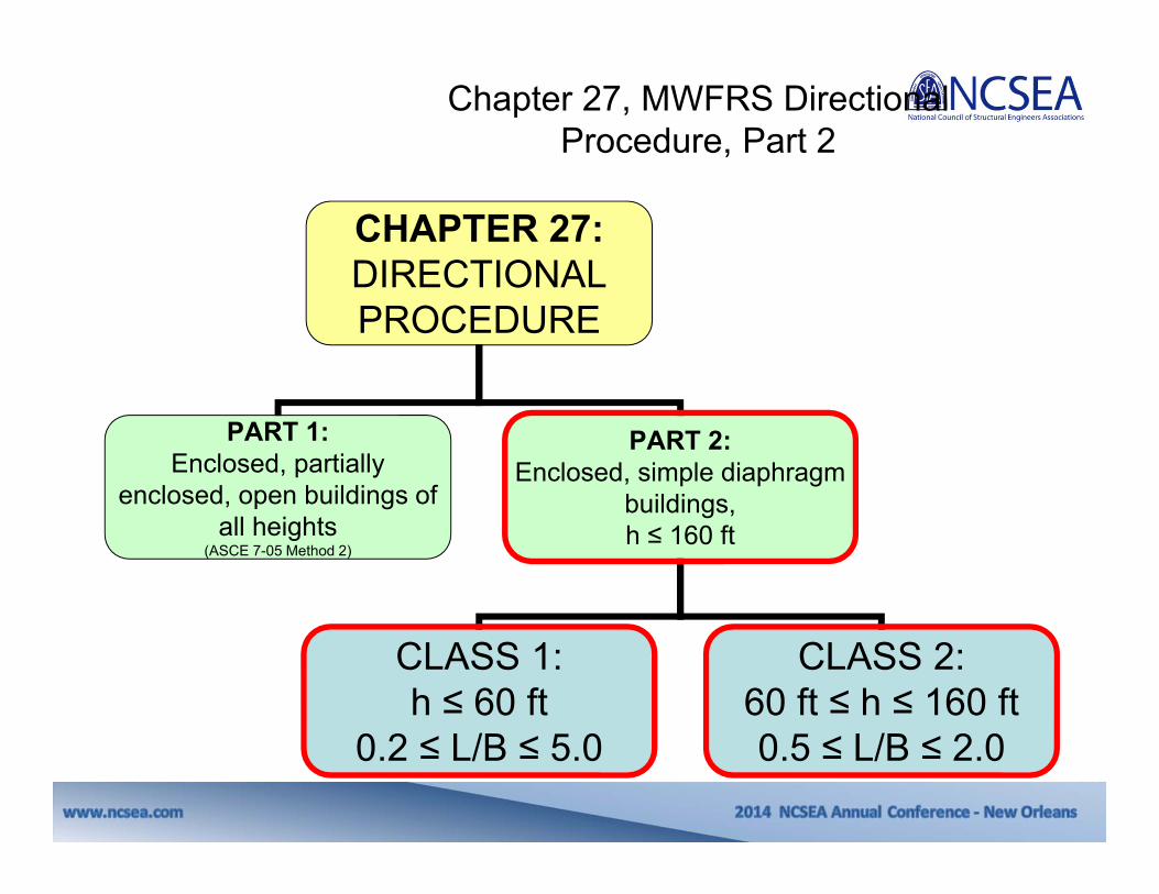
CHAPTER 27:DIRECTIONAL PROCEDURE
PART 1:Enclosed, partially
enclosed, open buildings of all heights
(ASCE 7-05 Method 2)
PART 2:Enclosed, simple diaphragm
buildings, h ≤ 160 ft
CLASS 1:h ≤ 60 ft
0.2 ≤ L/B ≤ 5.0
CLASS 2:60 ft ≤ h ≤ 160 ft0.5 ≤ L/B ≤ 2.0
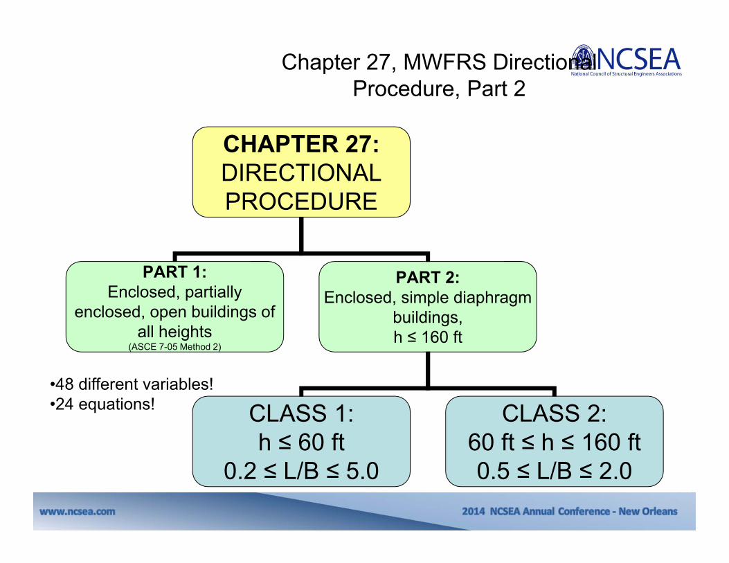
Chapter 27, MWFRS Directional Procedure, Part 2
•48 different variables!•24 equations!
CHAPTER 27:DIRECTIONAL PROCEDURE
PART 1:Enclosed, partially
enclosed, open buildings of all heights
(ASCE 7-05 Method 2)
PART 2:Enclosed, simple diaphragm
buildings, h ≤ 160 ft
CLASS 1:h ≤ 60 ft
0.2 ≤ L/B ≤ 5.0
CLASS 2:60 ft ≤ h ≤ 160 ft0.5 ≤ L/B ≤ 2.0
Chapter 27, MWFRS Directional Procedure, Part 2
66
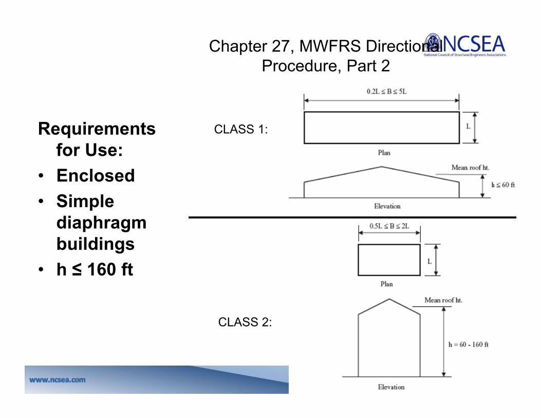
Requirements for Use:
• Enclosed• Simple
diaphragm buildings
• h ≤ 160 ft
CLASS 1:
CLASS 2:
Chapter 27, MWFRS Directional Procedure, Part 2

67
Simple Diaphragm Building
Wind
Wind pressure applied to windward wall.
Diaphragms receive edge loading from the windward wall and distribute the loads to the shear walls.
Shear walls receive the loads from the diaphragms and transfer the loads to the foundation.
A building in which both windward and leeward wind loads are transmitted by roof and vertically spanning wall assemblies through continuous floor and roof diaphragms, to the MWFRS.

Question: What are good or bad examples of “simple diaphragm buildings”?Answer:
Bad:•Metal buildings (horizontally spanning girts).•Building with expansion joints in the MWFRS.
Good:•Light frame construction with plywood shear walls.•CMU wall buildings.•Concrete frames.•Steel frames with vertically spanning walls and diaphragm floors and roofs.
Simple Diaphragm Building
Chapter 27, MWFRS Directional Procedure, Part 2
70
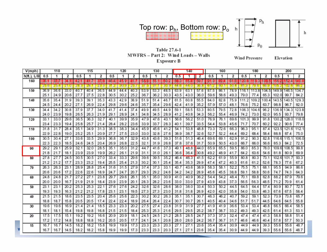
Top row: ph, Bottom row: po

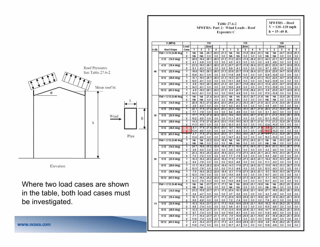
Chapter 27, MWFRS Directional Procedure, Part 2
48.8 psf
36.4 psf

72
Answer: Note 27.6.1…
- For Class 1 building with L/B values less than 0.5, use wind pressures tabulated for L/B = 0.5.
- For Class 1 building with L/B values greater than 2.0, use wind pressures tabulated for L/B = 2.0.
Question: If this method applies for 0.2 ≤ L/B ≤ 5, why does the table only include L/B from 0.5 to 2.0?
Chapter 27, MWFRS Directional Procedure, Part 2
74
Where two load cases are shown in the table, both load cases must be investigated.

75

Question: What if I’m not in Exposure C?Answer: Adjustment factor per 27.6-2.
Chapter 27, MWFRS Directional Procedure, Part 2

77
Answer: Footnote 4, Table 27.6-1…“Distribution of tabulated net wall pressures between windward and leeward wall faces shall be based on the linear distribution of total net pressure with building height as shown above and the leeward external wall pressures assumed uniformly distributed over the leeward wall surface acting outward at 38% of ph for 0.2 ≤ L/B ≤ 1.0 and 27% of ph for 2.0 ≤ L/B ≤ 5.0. Linear interpolation shall be used for 1.0 < L/B < 2.0. The remaining net pressure shall be applied to the windward walls as an external wall pressure acting towards the wall surface. Windward and leeward wall pressures so determined do not include effect of internal pressure.”
Question: Is it possible to determine windward and leeward pressures rather than a total net pressure?
Chapter 27, MWFRS Directional Procedure, Part 2

78
Answer: Figure 27.6-2… Surprisingly simple! Question: How do I account for increased MWFRS pressures on my parapets?
At L/B=1
Chapter 27, MWFRS Directional Procedure, Part 2
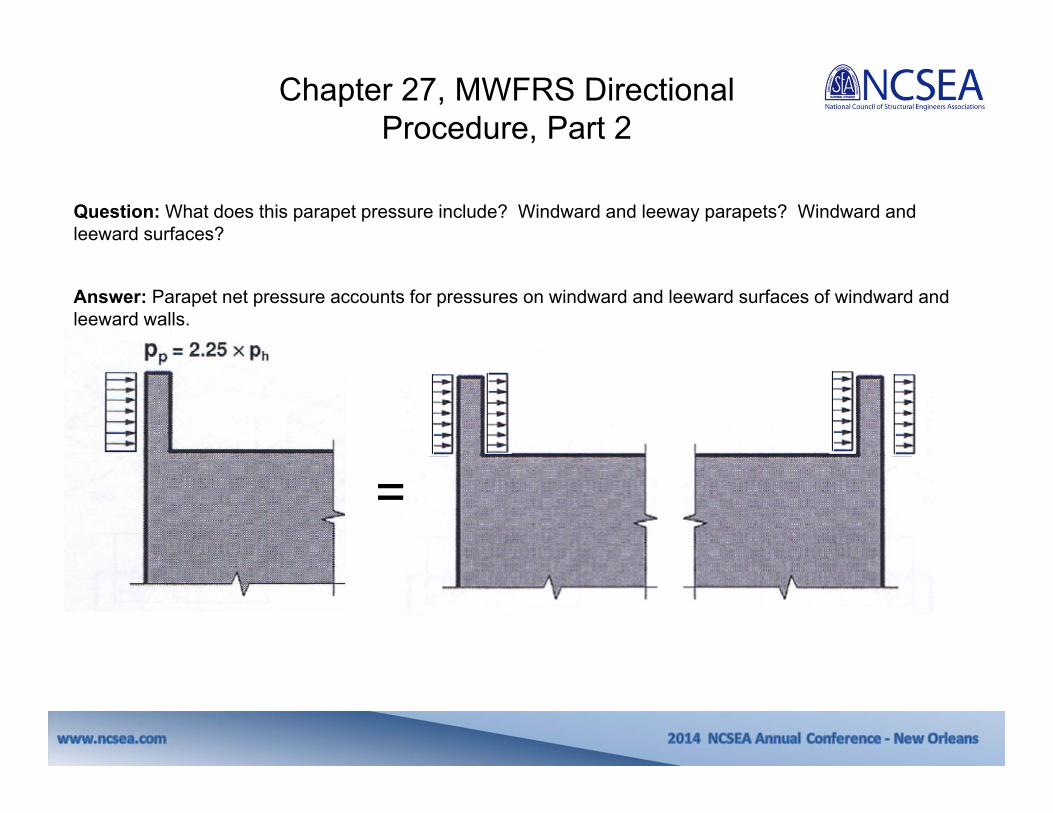
Answer: Parapet net pressure accounts for pressures on windward and leeward surfaces of windward and leeward walls.
Question: What does this parapet pressure include? Windward and leeway parapets? Windward and leeward surfaces?
=
Chapter 27, MWFRS Directional Procedure, Part 2

80
Answer: Footnote 2, Table 27.6-1…“Side wall external pressures shall be uniform over the wall surface acting outward and shall be taken as 54% of the tabulated ph pressure for 0.2 ≤ L/B ≤ 1.0 and 64% of the tabulated ph pressure for 2.0 ≤ L/B ≤ 5.0. Linear interpolation shall apply for 1.0 < L/B < 2.0. Side wall external pressures do not include effect ofinternal pressure.”
Question: How do I account for net pressure distribution on sidewalls?
Chapter 27, MWFRS Directional Procedure, Part 2

Combine net wall and roof pressures.
Pressures on the windward, leeward, and sidewalls and on roof and parapet are applied simultaneously.
Chapter 27, MWFRS Directional Procedure, Part 2

Answer: Yes. Section 27.6.3…“The effect of vertical wind loads on any roof overhangs shall be based on the application of a positive wind pressure on the underside of the windward overhang equal to 75% of the roof edge pressure from Table 27.6-2 for Zone 1 or Zone 3 as applicable. This pressure shall be applied to the windward roof overhang only and shall be applied simultaneously with other tabulated wall and roof pressures as shown in Fig. 27.6-3.”
Question: Does this simplified method allow me to account for overhangs for MWFRS pressures?
Chapter 27, MWFRS Directional Procedure, Part 2

Answer: Yes. The MWFRSs in each direction need to be designed for the wind load cases defined in Figure 27.4-8.The only exception: Torsional cases 2 and 4 do not need to be considered for buildings that meet with spatial distribution and stiffness of the MWFRSs provided in new Appendix D.
Question: If I use Chapter 27 Part 2 to calculate my wind pressures, do I need to consider torsion?
Chapter 27, MWFRS Directional Procedure, Part 2
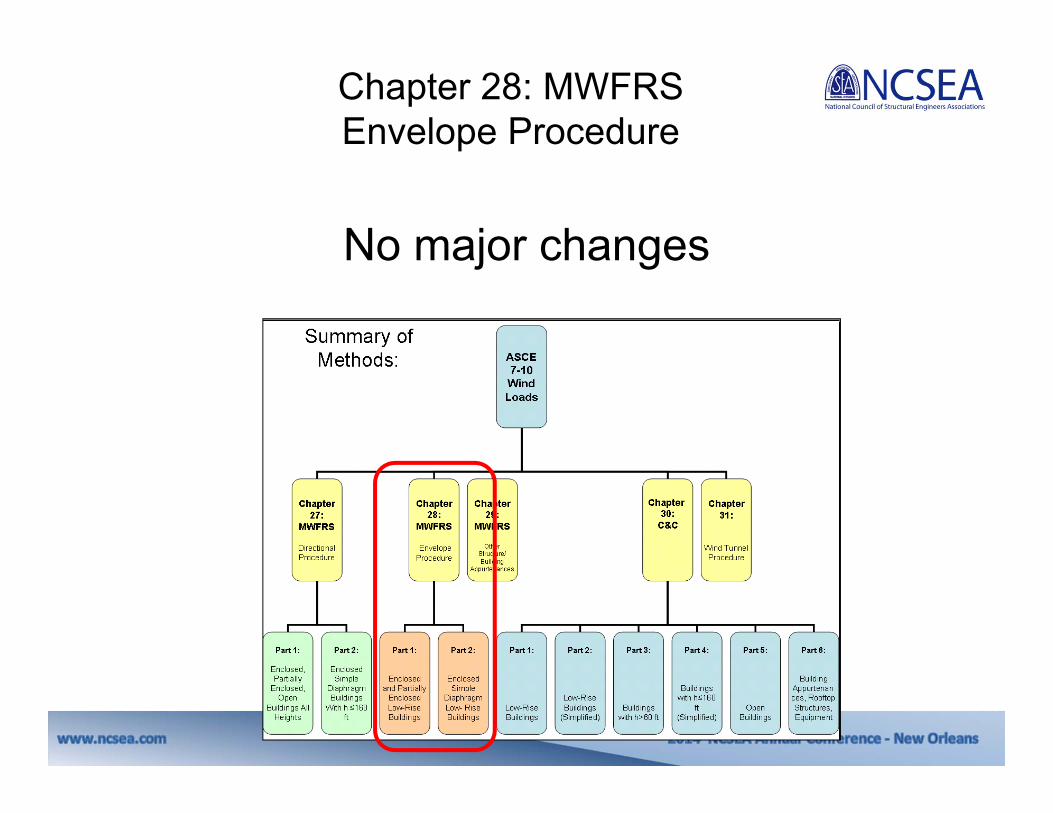
No major changes
Chapter 28: MWFRS Envelope Procedure

A couple of larger changes, additions….
Chapter 29: MWFRS Other Structures

86
Chapter 29: MWFRS Other Structures and Appurtenances
• Signs• Rooftop structures• Other structures
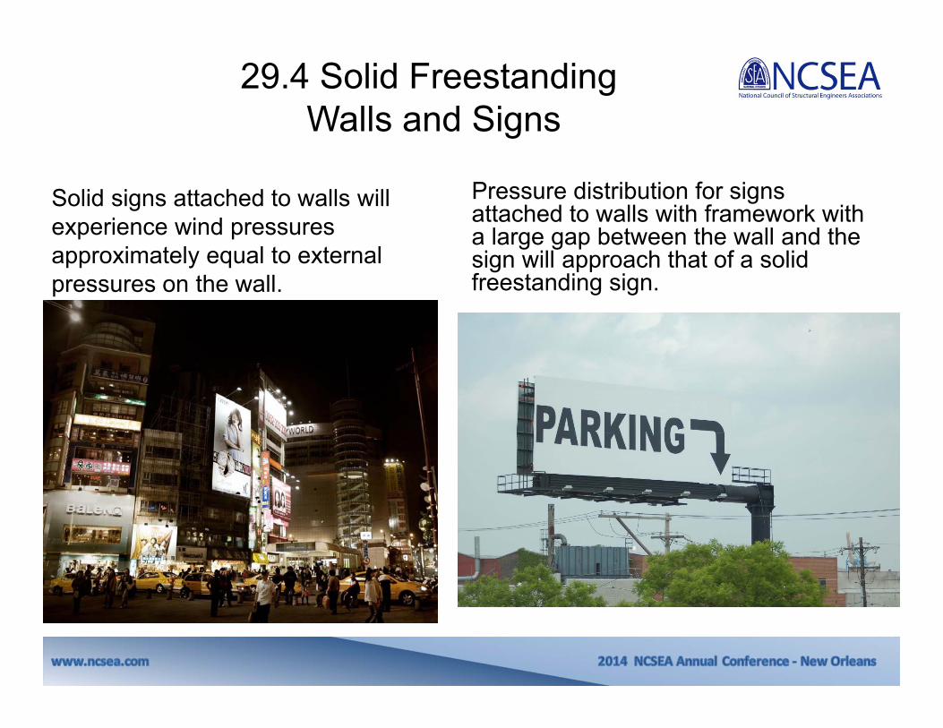
29.4 Solid FreestandingWalls and Signs
Solid signs attached to walls will experience wind pressures approximately equal to external pressures on the wall.
Pressure distribution for signs attached to walls with framework with a large gap between the wall and the sign will approach that of a solid freestanding sign.

•The wind pressure on a solid sign attached to the wall of a building: Use Chapter 30 (C&C), with the internal pressure coefficient, GCpi =0.•Also applicable to solid signs attached to, but not in direct contact, provided:
•The gap between the sign and wall is no more than 3 ft, and •The edge of the sign is at least 3 ft in from free edges of the wall.
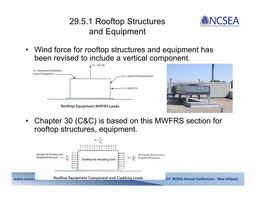
29.5.1 Rooftop Structuresand Equipment
• Wind force for rooftop structures and equipment has been revised to include a vertical component.
• Chapter 30 (C&C) is based on this MWFRS section for rooftop structures, equipment.

No major changes to Parts 1, 2, 3, 5, 6….Chapter 30: C&C
AS
CE
7-05M
ethod 2Low
-Rise
AS
CE
7-05M
ethod 1
AS
CE
7-05M
ethod 2>60 ft and A
lt.
AS
CE
7-05M
ethod 2
AS
CE
7-05M
ethod 2

Chapter 30: C&C- Part 4

92
Chapter 30: C&C- Part 4

Chapter 30: C&C- Part 4

Chapter 30: C&C- Part 4
Similar to MWFRS, we adjust the tabulated wind pressure for Exposure B or D, as needed. This term is called EAF (Exposure Adjustment Factor).

95
Question:What tributary area is the tabulated value based on? Is there a way to adjust the pressure for my actual tributary area?
Answer: Pressures in Table 30.7-2are based on an effective wind area of 10 ft2. Reductions in wind pressure for larger effective wind areas may be taken based on the reduction multipliers (RF) shown in the table.
This term is called RF (Reduction Factor).
Chapter 30: C&C- Part 4

Chapter 30: C&C- Part 4

Answer: Section 30.7.1.2. Two cases to consider: Question: How do I determine C&C wind pressures on my parapets?
p1= Positive wall pressure for Zone 4 or 5p2= Negative roof pressure for Zone 2 or 3
p3= Positive wall pressure for Zone 4 or 5p4= Negative wall pressure for Zone 4 or 5
CASE A CASE B
Chapter 30: C&C- Part 4

Chapter 30: C&C Part 6 Roof Overhangs

SOFFIT DESIGN:•The hurricanes of 2004 provided fresh evidence of the importance of properly designing soffits. •Many buildings suffered minimal damage other than loss of the soffit material. •However, due to wind and rain, there is often significant damage to the inside of the building when soffits fail.
Chapter 30: C&C Part 6 Roof Overhangs

100
Question: What wind pressure should I use for design of a soffit under an eave? In ASCE 7-05 the C&C GCp provided the total uplift on the overhang. It wasn’t clear how to separate the top from the bottom surface pressure to properly design a soffit.
Research and analysis shows that the pressure on the underside of the roof overhang is the same as the pressure on the adjacent wall.
Top Surface Pressure: Pressure calculated using GCp for overhangs minus the surface pressure calculated below.
Bottom Surface Pressure: Pressure calculated using GCpfor walls based on the effective wind area of the soffit.
Chapter 30: C&C Part 6Roof Overhangs

New lower limits are relocated from Commentary to the
Standard… 31.4.3
Chapter 31: Wind Tunnel Procedures

Questions?