
Situ Resource Utilization (ISRU) Development & Incorporation Plans

THE LUNAR ANALOGUE ISRU ROVER �ARTEMIS JR.�
Nick Cristello (1), Michele Faragalli (1), Brad Jones (1), Peter Iles (1), Ewan Reid (1), Jason Muise (1), Peter Visscher (2), Dale Boucher (3), Vincent Simard-Bilodeau (4), Dimi Apostolopoulos (5), Paul Rocco (6), Martin
Picard (7)
(1) Neptec Design Group, 302 Legget Dr, Kanata, ON, K2K 1Y5, Canada, Email: [email protected]. (2) Ontario Drive and Gear, 220 Bergey Court, New Hamburg, ON, N3A 2J5, Canada, Email: [email protected].
(3) Northern Center for Advanced Technology, 1545 Maley Dr, Greater Sudbury, ON P3A 4R7, Canada, Email: [email protected].
(4) NGC Aerospace, 1650 rue King Ouest, Bureau 202, Sherbrooke, QC, J1J 2C3, Canada, Email: [email protected].
(5) ProtoInnovations, Ice House Building, 100 43rd Street, Pittsburgh, PA 15201, USA, Email: [email protected].
(6) Provectus Robotics Solutions, 13 Bracewood Way, Nepean, ON K2J 4Y3, Canada, Email: [email protected].
(7) Canadian Space Agency (CSA), 6767 Route de L�Aeroport, Saint-Hubert, QC, J3Y 8Y9, Canada, Email: [email protected].
ABSTRACT
The Regolith and Environment Science and Oxygen and Lunar Volatiles Extraction (RESOLVE) project aims to verify the presence of water and other volatiles on the Moon, and to serve as a precursor for future prospecting missions. The Artemis Jr. rover was developed as the surface mobility component of the RESOLVE project, and was specifically designed to accommodate In Situ Resource Utilization payloads for analogue field testing. This paper outlines the design of the Artemis Jr. rover, with emphasis on the mobility, power, avionics and navigation subsystem design and performance. The rover performance is quantified by a review of results obtained during the NASA-led ISRU analogue mission in July 2012.
1 LUNAR IN-SITU RESOURCE UTILIZATION
A major challenge in establishing a permanent lunar outpost is the quantity of construction materials and consumables required to be brought from Earth. In particular, large quantities of oxygen, hydrogen, and water are necessary in human exploration missions. Liquid oxygen and hydrogen is used as chemical propellant and astronauts need consumable water, and gaseous oxygen and hydrogen for life support systems. Water can also be used as a protective shield in habitats against radiation. Until the impact of the Lunar Crater Observation and Sensing Satellite (LCROSS) at Cabeus Crater on the Moon�s South Pole, the evidence of water ice on the Moon was inconclusive. Previously, extracting oxygen or hydrogen from the lunar soil, or regolith, was thought to require large amounts of energy and soil and an existing surface infrastructure to process the
regolith. Water ice and volatiles are now known to exist in permanently shadowed areas of the Moon. Volatile traps or �hot spots� are thought to exist at the lunar poles where incidental light from the Sun does not reach the bottom of craters. The bi-products of volatile resource extraction are also considered advantageous. The lunar regolith can be used to bury habitats for protection against micro-meteorite impacts and radiation, create protective barriers and berms between habitats and landing pads, and be sintered for the construction of roads or bricks.
1.1 Lunar ISRU Precursor mission: RESOLVE
While LCROSS and the Lunar Reconnaissance Orbiter (LRO) proved the existence of water ice and other volatiles in permanently shadowed craters of the South Pole, the quantity and distribution of the resources remains unconfirmed [1]. As such, in-situ measurement and surveying of the distribution of valuable resources is required to confirm their use for future manned exploration missions. Furthermore, techniques for resource extraction from regolith remain untested. To answer these outstanding questions, NASA has proposed a lunar In-Situ Resource Utilization (ISRU) prospecting mission, RESOLVE [2]. The Regolith and Environment Science and Oxygen and Lunar Volatiles Extraction (RESOLVE) mission will survey a lunar South Pole landing site using four science instruments (gas chromatograph, Mass Spectrometer, Neutron Spectrometer, Near-IR Spectrometer), a sample acquisition system (drill, auger) and a high temperature chemical reactor mounted on a rover. The drill and rover will be provided by the Canadian Space Agency (CSA). A design reference mission (DRM) study was completed in [3]; Figure 1 summarizes the mission parameters.

Figure 1. RESOLVE DRM Parameters
1.2 RESOLVE Analogue Mission Simulation
In preparation for a flight mission to deploy the RESOLVE payload, NASA has been performing demonstrations of ISRU equipment for almost 10 years [2]. Most recently a collaborative effort between NASA and its partners, including the CSA and the Pacific International Space Center for Exploration Systems (PISCES), demonstrated the prototype RESOLVE ISRU payload as integrated onto a terrestrial prototype rover in the Pu�u Hawaihini (PuuH) valley on the slopes of Mauna Kea, Hawaii, in July 2012 [4]. The motivation for demonstration at this location arises from the terrain and soil properties found there; the mineral composition and distribution of particle sizes is similar to lunar regolith. To demonstrate the remote operation capabilities of the equipment and to simulate a representative mission environment, mission control centre was established at Hale Pohaku (HP, 1.5km from PuuH) along with several support centers on the mainland including ExDOC in Montreal, Canada. This analogue mission simulation exercised the ISRU equipment over a five (5) day period. The primary objective of the mission simulation conducted in Hawaii was for RESOLVE to locate, characterize and map volatiles that may be present at
the test site. The terrestrial prototype Artemis Jr. rover, funded by CSA, was used to provide mobility and localization to the RESOLVE payload. The Artemis Jr. rover was developed by a consortium of companies, the majority of which were Canadian, and funded by CSA, with a primary goal of accommodating the RESOLVE payload. The following sections introduce the Artemis Jr. rover design and present key results from the operation during the RESOLVE mission simulation in Hawaii.
2 ROVER SYSTEMS DESIGN
Artemis Jr. was designed as a terrestrial prototype ISRU platform and can accommodate a variety of science payloads and instruments in its U-shaped chassis. Figure 2 depicts the 260 kg Artemis Jr. rover with and without the RESOLVE payload.
Figure 2. Artemis Jr. without and with the RESOLVE payload
The Artemis Jr. rover is composed of several key subsystems; the chassis and mobility subsystem, the power and avionics subsystem, the navigation and vision subsystem and the communications and control subsystem. What follows is an overview of these key subsystems, outlining the emphasis on payload integration and accommodation.
2.1 Chassis and Mobility Subsystem
The chassis and mobility subsystem consists of a four-wheeled skid-steer platform, with flexible metallic wheels linked through a passive geometric suspension system which provides mobility in soft soil and rough terrain. The mobility subsystem itself is subdivided into several key elements, namely the chassis, the drive units, the suspension and the wheels [5]. The chassis topology, and open �U� shape frame, was developed to optimize the potential for integration with RESOLVE and other payloads [6]. While many rover designers will centrally locate all internal avionics the options for payload integration then becomes limited. Conversely, the Artemis Jr. chassis was designed with a central payload bay, having all peripheral equipment

surrounding this bay. The chassis structure surrounding the payload bay was designed to house all avionics and electronic equipment and provide an environmentally protected enclosure for sensitive components. The benefit of this architectural shift can be seen by an overall lower Centre of Gravity (CoG) of the integrated rover, by increased access of the RESOLVE (or other) payloads to the surface, and by an overall reduction in vehicle size. Figure 3 below shows the integration of the RESOLVE payload with the Artemis Jr. during the Mission Simulation in Hawaii.
Figure 3. Integration of RESOLVE with Artemis Jr.
The drive units of the Artemis Jr. rover represent the vehicle transmission, responsible for transmitting torque from the traction motors to the wheels. Each of the two (2) walking beam drive units on the rover includes one (1) traction motor and two (2) wheels. Since the Artemis Jr. rover employs skid-steering, and since each traction motor transmits torque to two (2) wheels simultaneously, only two (2) motors are required for locomotion. This approach reduces complexity, mass and cost. The drive units are pivotally mounted to the rover chassis at a height to provide sufficient ground clearance to avoid small and traverse large obstacles, while still respecting the needs of the payload to access the regolith for sample extraction; 35 cm. Artemis Jr. utilizes a geometric suspension, linking each drive unit to the other, to provide a terrain-averaging effect. Through the use of a differential gearbox, the suspension system can operate in a completely passive mode � responding to undulating terrain � or can be activated independently of terrain to �pitch� the rover chassis to avoid obstacles, level the chassis and shift the CoG during traverses on slopes, and/or lower payloads closer to the surface when required. All sensitive components of the suspension system � namely the differential gearbox and the suspension actuator � are housed inside the main chassis enclosure for protection against the environment. Figure 4 demonstrates the pitching capability of the suspension, and how it operates to
bring payloads such as RESOLVE closer or moved further from the surface, as required.
Figure 4. Artemis Jr. Suspension Pitch
The metallic wheels of Artemis Jr. offer a unique solution to the challenges of providing a compliant wheel in a harsh lunar environment. The wheels used on Artemis Jr. provide increased traction in the lunar-like environment of PuuH, and afford a level of vibration attenuation not available using rigid wheels. The metal wheels shown in Figure 2, Figure 3, and Figure 4 are approximately 60 cm in diameter and at 14 kg each, have a mass slightly less than similarly sized pneumatic tires. The size of the wheels was optimized to provide the required ground clearance and tractive force while respecting the overall vehicle design envelope and considering the required vibration attenuation of the payloads.
2.2 Power and Avionics Subsystem
The power and avionics subsystem of Artemis Jr. is composed of several key elements, namely the energy storage system (batteries), power management and distribution system, the Central Electronics Unit (CEU) and the motion control system. Each of these elements is housed within the chassis electronics enclosure. Energy storage on Artemis Jr. is provided through a pair of lithium-ion battery packs, custom designed to fit within the frame rails of the rover chassis. Such a placement maintains an even mass distribution, maximizes payload volume and increases available space inside the chassis for electronics. The nominal energy capacity of each battery pack is 2.57 kWhr. At full charge each pack has a voltage of 54 V and can drive up to 110 A continuously and 880 A for 2 s pulses. The packs are connected in parallel resulting in a system which can deliver 11.9 kW of continuous power. With a total energy capacity of over 5 kWhr, the Artemis Jr. rover was able to support the RESOLVE payload during each flight day of the mission simulation without the need to recharge. Power to the RESOLVE payload was supplemented by a small solar panel, installed on Artemis Jr., although for the purposes of this mission simulation it was not
used to recharge the Artemis Jr. batteries. Figure 5 shows an image of the 13 cell, 27 kg battery pack used in Artemis Jr.
Figure 5. Artemis Jr. Battery Pack
The power management and distribution system was designed to provide modularity and flexibility to the various elements within the Artemis Jr. rover, as well as the expected payloads. Non-isolated power buses were available for internal use at 28 V, 12 V, 5 V and 3.3 V. The majority of internal systems and sensors use 28 V power, which is switched using a solid state controller. In particular three (3) independent 28 V power channels were provided for use by the RESOLVE payload rated at 12 A each. Artemis Jr. is able to deliver up to 1 kW of power to the payload, should it be required. Figure 6 shows the connector panel atop the Artemis Jr. chassis electronics enclosure used to interface with the RESOLVE payload. Note that this image also shows the data port connections for interface with the Artemis Jr. control system, which will be discussed in subsequent sections.
Figure 6. Artemis Jr. Payload Power and Data Ports
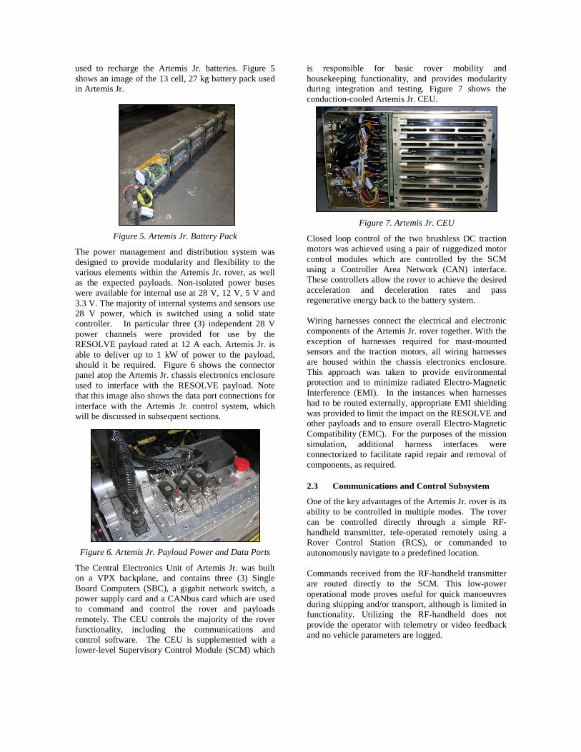
The Central Electronics Unit of Artemis Jr. was built on a VPX backplane, and contains three (3) Single Board Computers (SBC), a gigabit network switch, a power supply card and a CANbus card which are used to command and control the rover and payloads remotely. The CEU controls the majority of the rover functionality, including the communications and control software. The CEU is supplemented with a lower-level Supervisory Control Module (SCM) which
is responsible for basic rover mobility and housekeeping functionality, and provides modularity during integration and testing. Figure 7 shows the conduction-cooled Artemis Jr. CEU.
Figure 7. Artemis Jr. CEU
Closed loop control of the two brushless DC traction motors was achieved using a pair of ruggedized motor control modules which are controlled by the SCM using a Controller Area Network (CAN) interface. These controllers allow the rover to achieve the desired acceleration and deceleration rates and pass regenerative energy back to the battery system. Wiring harnesses connect the electrical and electronic components of the Artemis Jr. rover together. With the exception of harnesses required for mast-mounted sensors and the traction motors, all wiring harnesses are housed within the chassis electronics enclosure. This approach was taken to provide environmental protection and to minimize radiated Electro-Magnetic Interference (EMI). In the instances when harnesses had to be routed externally, appropriate EMI shielding was provided to limit the impact on the RESOLVE and other payloads and to ensure overall Electro-Magnetic Compatibility (EMC). For the purposes of the mission simulation, additional harness interfaces were connectorized to facilitate rapid repair and removal of components, as required.
2.3 Communications and Control Subsystem
One of the key advantages of the Artemis Jr. rover is its ability to be controlled in multiple modes. The rover can be controlled directly through a simple RF-handheld transmitter, tele-operated remotely using a Rover Control Station (RCS), or commanded to autonomously navigate to a predefined location. Commands received from the RF-handheld transmitter are routed directly to the SCM. This low-power operational mode proves useful for quick manoeuvres during shipping and/or transport, although is limited in functionality. Utilizing the RF-handheld does not provide the operator with telemetry or video feedback and no vehicle parameters are logged.

For mission-like scenarios and testing operations, the Artemis Jr. utilizes the control software installed on the rover CEU to provide advanced functionality. Through the RCS, the operator is able to communicate wirelessly to the rover and tele-operate it over large distances. The RCS also provides the functionality to send the rover autonomous navigation commands such that the rover will navigate to a waypoint, while avoiding obstacles, without direct user input. The RCS is a Linux-based software application, which may be installed on any laptop or personal computer, and connects to the rover wirelessly using either a 900 MHz or 2.4 GHz radio communication. For diagnostic operations, the RCS can be connected to the rover using a standard Ethernet connection. The RCS provides a complete set of tele-operational controls through the use of a gamepad controller.
Figure 8. RCS Internal Components Screenshot
Figure 9. RCS Telemetry Screenshot
The RCS application includes a multitude of displays to provide information to the user about all aspects of the Artemis Jr. rover. Through the RCS the operator may also select which video streams to display for use with tele-operation and/or observation during autonomous navigation. Figure 8 shows a screenshot of the Artemis Jr. RCS Internal Components tab, which provides insight into the operational state of key components of the rover. To maximize the usage of the available bandwidth, the telemetry and video streams from the Artemis Jr. rover are fully configurable. Furthermore, to maximize mission success, the telemetry stream from the rover was also made available to the RESOLVE ground software. Rover telemetry items such as heading and location were essential for the RESOLVE science team to accurately map the volatiles found. An example of some of the telemetry which is available from the rover is shown in Figure 9.
2.4 Navigation and Vision Subsystem
The navigation and vision subsystem of the Artemis Jr. rover is composed of several key elements designed to provide the necessary level of relative and absolute localization, navigation ability and situational awareness. Accurate relative localization is achieved using wheel odometry, inertial sensing, a Sun-sensing heading estimator and two complementary visual odometry techniques. For absolute localization, the rover can use a lander based tracking system or a digital elevation model comparison technique. More details of the localizations system can be found in [7]. The Artemis Jr. navigation system therefore allows the rover to perform accurate localization and autonomous navigation using only its own sensors, and can be augmented with surface assets which could reasonably be expected to be part of a lunar mission.
Figure 10. Mast-Mounted Vision / Navigation Sensors
In particular, mounted atop the Artemis Jr. mast is a suite of vision sensors used to achieve the desired performance. A pair of stereo navigation cameras provides the primary input to the navigation algorithm

used for autonomous navigation and control, and for visual odometry. In addition, a science camera and illuminator is mounted on a Pan-Tilt Unit (PTU) to provide video feedback to the operator during tele-operated manoeuvres and/or inspection of the rover or payload as required. Figure 10 shows the sensors mounted on the Artemis Jr. mast: the aforementioned navigation and science cameras, the prism used for absolute localization and the sun-sensing camera to prevent heading drift.
Mounted inside the chassis electronics enclosure is an Inertial Measurement Unit (IMU) to measure relative angular motion, roll and pitch, and an under-belly camera with a large Field of View (FoV) for situational awareness under the rover and support for drilling operations. A second pair of stereo visual odometry cameras is also housed inside the chassis electronics enclosure, facing downward and focused on the terrain below, to complement the primary navigation cameras on the mast. Figure 11 shows a view from the under-belly camera, being used to assist in positioning of the RESOLVE drill over the target site at PuuH.
Figure 11. Artemis Jr. Under-belly Camera View
Figure 12. Artemis Jr. Landing Zone Localizer
In addition to performing relative localization using the mast-mounted navigation cameras and chassis-mounted odometry cameras, the Artemis Jr. rover can perform absolute localization with respect to a lander or other fixed asset. In particular, the rover was demonstrated at PuuH with a �Landing Zone Localizer� system, mounted atop the mock lander, which allowed the rover to accurately localize itself with respect to this lander. Figure 12 shows the Landing Zone Localizer
mounted atop the NASA supplied mock lander during the mission simulation. In addition to the relative and absolute localization capabilities, the Artemis Jr. navigation system can also be used to plan and execute traverses autonomously between waypoints, while avoiding obstacles. This ability permits the mission operators to plan the most efficient a route to search for volatiles while relying on the rover to avoid any obstacles that may be encountered. To do this, Artemis Jr. employed the Reliable Autonomous Surface Mobility (RASM) navigation software, originally developed by Carnegie Mellon University (CMU) [8]. The user interface on the RCS supports the creation of mission specific scenarios, containing several waypoints that the operator may sequence through either autonomously or semi-autonomously.
3 ROVER PERFORMANCE
Prior to the start of the deployment, NASA and CSA defined a series of objectives for mission success. These objectives were classified into four categories: Mandatory, Highly Desirable, Desirable and Goals [4]. While Artemis Jr. contributed to the overall success of the mission through the completion of key objectives outlined above, Artemis Jr. also demonstrated success in other, specifically targeted, rover-metrics, which were measured outside of the primary simulation. As such the Artemis Jr. rover achieved multiple measures of success both within the simulation environment and during general mission support.
3.1 In Simulation Performance Measures
The primary (mandatory) objective of the analogue mission simulation was to travel 100 m on the surface to map the distribution of volatiles. Artemis Jr. recorded a total distance of over 1 km of in-simulation driving, during which time the RESOLVE payload was mapping volatiles, thereby addressing this objective early in the simulation. Figure 13 shows part of the path of the Artemis Jr. traverse overlaid on a Google Earth map, identifying the distribution of volatiles. By the same metric, Artemis Jr. was also able to address the desirable goal of mapping the horizontal distribution of volatiles over a point-to-point distance of 500 m.
Through successful collaboration with the RESOLVE team, the Artemis Jr. rover was also able to transport the payload to multiple sites to enable the DESTIN drill to perform coring operations at more than three locations, and also perform more than three augering operations in simulation. Figure 14 shows one of the augering operations conducted by DESTIN.

Figure 13. Detail of Artemis Jr. Traverse
Figure 14. DESTIN Conducting Augering Operation
To achieve these objectives required the Artemis Jr. to perform at a high level of reliability and accuracy, as demonstrated by the ability to navigate and localize the rover to the precision required for volatile extraction.
3.2 Rover-Specific Performance Measures
In addition to the predefined mission objectives, the Artemis Jr. rover demonstrated other measures of success with respect to the rover itself. In particular the Artemis Jr. rover was demonstrated to be a modular, flexible, robust, highly capable and adaptable rover capable of accommodating ISRU payloads. With more than 1 km of traverse in-simulation, and almost 2 km total distance travelled while on site at PuuH, the Artemis Jr. mobility system robustness and reliability was demonstrated. With no failures, the mobility system was able to transport RESOLVE to all of the predefined locations, and over all of the terrain required by the mission. The power system also demonstrated a high degree of robustness by offering a reliable source of power for both the rover and RESOLVE systems, without needing to pause or delay the mission simulation to recharge during a day. Most notably, the navigation system of the Artemis Jr. rover was instrumental in the completion of all mission
objectives. Although the Artemis Jr. was primarily operated in a tele-operation mode, approximately 10% of the traverses were completed in the fully autonomous mode. Throughout the mission, a relative localization performance of approximately 2% was demonstrated, and absolute localization of the rover of was achieved with an accuracy of less than 1 m over a distance of 500 m from the mock lander. Offering communications support to the RESOLVE payload, the Artemis Jr. was responsible for transmitting all telemetry for both RESOLVE and the rover to the command station in HP and ExDOC. This communication allowed for tele-operation control of the rover from ExDOC. Despite some preliminary challenges in the preparation of the field-network, once established, the Artemis Jr. rover communications and control system performed as expected.
4 PATH-TO-FLIGHT CONSIDERATIONS
While the analogue mission simulation conducted in Hawaii of 2012 was deemed a success, significant effort is yet required to advance Artemis Jr. to a flight-capable rover. In particular, the Artemis Jr. design will need to be re-examined, with particular emphasis on payload interface, environmental protection, communication and power / mass budgets.
4.1 Payload Interface Refinement
The Artemis Jr. rover has been optimized for use with the RESOLVE payload. However in the interest of minimizing integration and test efforts during the analogue mission, the two systems (rover and payload) were created in a modular fashion. Future (flight) programs would see a closer integration between the payload and rover in the areas of both mechanical and electrical interfaces. In particular, the payload superstructure, which would be used to mount all RESOLVE equipment, may be used as a structural element in the rover chassis, to minimize mass. Furthermore, a reduction in rover-to-payload connectors would minimize mass and potential sources for EMI. It is also recommended that all power rails be supplied by the rover, to minimize duplication and inefficiencies of power conversions within RESOLVE.
4.2 Environmental Protection
To contain costs and provide modularity during field testing, externally mounted sensors were left exposed to the environment. Also, Artemis Jr. was designed with a terrestrial based operating temperature range. Future considerations of the Artemis Jr. rover would encapsulate the sensitive electronics that must be mounted externally in an environmentally controlled

enclosure. Furthermore, heaters (and if need be coolers) would be implemented on the Artemis Jr. rover to accommodate the lunar temperature ranges described in the DRM of Figure 1. Further consideration must also be given to other environmental risk factors such as radiation, micrometeorite debris and regolith dust.
4.3 Communication and Control
The current Artemis Jr. rover has been developed considering flight-like communications restrictions, but changes will be necessary. The Artemis Jr. telemetry stream will need to be customized to accommodate the available bandwidth and communication delay, as well as make concessions for payload bandwidth requirements. The rover control/feedback method for driving must also be tolerant of the lunar-like delay that can be expected. Current communications on the Artemis Jr. is facilitated through the use of either a 900 MHz or 2.4 GHz radio, which will not be possible in a lunar mission. A flight-capable Artemis Jr. rover must therefore investigate the trade-off between multiple types of communications, including rover Direct-To-Earth (DTE) as well as Rover-to-Lander communications and Lander DTE communications.
4.4 Power and Mass Budgeting
As mentioned above, the total energy capacity of the Artemis Jr. rover is approximately 5.1 kWh. Future development of Artemis Jr. would augment the existing energy storage system to include a secondary method to recharge the batteries, such as a solar panel. Considering a fairly consistent source of power generation from a solar panel, the energy capacity of flight-capable Artemis Jr. battery system may be reduced to realize a reduction in system mass. At 260 kg, and carrying a 125 kg payload, the Artemis Jr. rover has already demonstrated an impressive rover-to-payload mass ratio. However, as outlined in the DRM above, the mass of the rover must be reduced to approximately 170 kg. This represents a significant challenge that can only be met by a system-wide re-evaluation of the design considerations and constraints. To track the performance of the Artemis Jr. rover in the next development cycle, detailed power and mass budgets must therefore be produced which include not only inputs form rover subsystems, but equally importantly from the RESOLVE payload subsystem.
5 CONCLUSIONS
The four-wheeled, skid-steer, autonomously operated Artemis Jr. rover has been developed primarily to
accommodate payloads, in particular ISRU payloads such as the NASA RESOLVE package. The integration with the RESOLVE payload culminated with a 5-day mission simulation on the slopes of Mauna Kea, Hawaii in July 2012. Considering payload requirements and constraints from the outset of the design has enabled the optimization of each of the Artemis Jr. subsystems to most effectively interface with and accommodate ISRU payloads. While significant advancements have already been made in the mechanical and electrical interfaces between the rover and payload, further development is required. Advancing the program to a flight-capable system will require further collaboration between the rover and payload systems to ensure maximum efficiency in the areas of environmental protection, communication bandwidth, power consumption and mass targets. However, as already demonstrated with the successful integration and deployment of Artemis Jr. and RESOLVE, it is clear that such collaboration is feasible.
6 REFERENCES
[1] Taylor, G., et. al. (2007). RESOLVE: Bridge Between Early Lunar ISRU and Science Objectives. European Planetary Science Congress, (2)0012, Potsdam, Germany.
[2] Sanders, G.B., et. al. (2011). RESOLVE for Lunar Polar Ice/Volatile Characterization Mission. EPSC-DPS Joint Meeting 2011, (6)1605, Nantes, France.
[3] George, J.A., et. al. (2012). RESOLVE Mission Architecture for Lunar Resource Prospecting and Utilization. 43rd Lunar and Planetary Science Conference, 2583, The Woodlands, TX.
[4] Sanders G.B., et. al. (2012). RESOLVE Lunar Ice/Volatile Payload Development and Field Test Status. Annual Meeting of the Lunar Exploration Analysis Group, Greenbelt, Maryland.
[5] Visscher P., et. al. (2013). Artemis Jr. Rover Mobility Platform. 51st AIAA Aerospace Sciences Meeting Including New Horizons Forum and Aerospace Exposition, 2013-0438, Grapevine, Texas.
[6] Jones, B., et. al. (2010). The Juno Rover � An Extraction Vehicle for In Situ Resource Utilization. 15th CASI-ASTRO Conference, Toronto, Ontario.
[7] Iles, P., et. al. (2012). Localization System of the Lunar Analogue Rover Artemis Jr. GLEX-2012.03, P. 2x12627.
[8] Wettergreen, D., et al. (2012). Developing a Framework for Reliable Autonomous Surface Mobility. I-SAIRAS, Turin, Italy.