
The High Speed Rail Linking Three Airports Project Outline … 3 Vol... · 2018-06-14 · AASHTO...
412
Transcript of The High Speed Rail Linking Three Airports Project Outline … 3 Vol... · 2018-06-14 · AASHTO...
The High Speed Rail Linking Three Airports Project Outline Specifications
Volume 3 : Outline Specifications i Table of Contents Volume 3/1 : The Rail-Related Works of The Project Part 2 : Outline Construction Specifications Book 1//2 : Civil Works
VOLUME 3 : OUTLINE SPECIFICATIONS
VOLUME 3/1 : THE RAIL-RELATED WORKS OF THE PROJECT
PART 2 - OUTLINE CONSTRUCTION SPECIFICATIONS
BOOK 1 OF 2: CIVIL WORKS
Table of Contents
Page
SECTION 1: STANDARDS
1.1 Introduction ....................................................................................................................................1-1
SECTION 2: EARTHWORKS
2.1 Excavation .......................................................................................................................................2-1 2.2 Fill .....................................................................................................................................................2-4 2.3 Test ...................................................................................................................................................2-7 2.4 Landscaping ..................................................................................................................................2-8 2.5 Selected Material A .....................................................................................................................2-8 2.6 Sand Drainage Layer ................................................................................................................ 2-11 2.7 Subballast and Subbase ......................................................................................................... 2-11
SECTION 3: ROADWORKS
3.1 Subbase ...........................................................................................................................................3-1 3.2 Aggregate Base ...............................................................................................................................3-3 3.3 Asphaltic Materials ........................................................................................................................ 3-4 3.4 Asphaltic Prime Coat ............................................................................................................... 3-10 3.5 Asphaltic Tack Coat ................................................................................................................... 3-11 3.6 Asphaltic Surface Treatment .................................................................................................. 3-12 3.7 Asphaltic Concrete Surfacing .................................................................................................. 3-18 3.8 Reinforced Concrete Pavement ............................................................................................. 3-29 3.9 Co-Ordination with Highway Agencies .................................................................................. 3-53 3.10 Road Marking, Traffic Signs and Traffic Signals ................................................................... 3-53
SECTION 4: PILING & DIAPHRAGM WALLING
4.1 General ............................................................................................................................................4-1 4.2 Concrete Piles ................................................................................................................................4-3 4.3 Precast Concrete Piles .................................................................................................................4-3
The High Speed Rail Linking Three Airports Project Outline Specifications
Volume 3 : Outline Specifications ii Table of Contents Volume 3/1 : The Rail-Related Works of The Project Part 2 : Outline Construction Specifications Book 1//2 : Civil Works
Table of Contents
Page
SECTION 4: PILING & DIAPHRAGM WALLING (Continued) 4.4 Cast In Place Piles .........................................................................................................................4-5 4.5 Pile Testing .....................................................................................................................................4-9 4.6 Diaphragm Walling ..................................................................................................................... 4-26
SECTION 5: CONCRETE 5.1 Concrete Materials ........................................................................................................................5-1 5.2 Concrete Workmanship ...............................................................................................................5-7 5.3 Precast Concrete ........................................................................................................................ 5-27
SECTION 6: PRESTRESSED MEMBERS 6.1 Prestressing Tendons ...................................................................................................................6-1 6.2 Precast Construction ....................................................................................................................6-3 6.3 Stressing Tendons ......................................................................................................................... 6-3 6.4 Testing by Concessionaire .......................................................................................................... 6-4 6.5 Pretensioning .................................................................................................................................. 6-4 6.6 Post-Tensioning ............................................................................................................................. 6-5 6.7 Protection of Tendons ................................................................................................................. 6-7 6.8 Ducts for Bonded Tendons (Internal Tendons) .................................................................... 6-7 6.9 Ducts for Bonded Tendons (Internal Tendons) .................................................................... 6-7 6.10 Prestressing Tendons - Trial Construction-Unbonded
Tendons (External Tendons) ...................................................................................................... 6-8 6.11 Prestressing Tendons - Temporary Tendons ......................................................................... 6-9 6.12 Casting .............................................................................................................................................. 6-9 6.13 Grouting of Prestressing Tendons .......................................................................................... 6-12
SECTION 7: STRUCTURAL STEEL WORKS 7.1 General ............................................................................................................................................7-1 7.2 Material Properties........................................................................................................................7-1 7.3 Testing ..............................................................................................................................................7-1 7.4 Fabrication ......................................................................................................................................7-1 7.5 Detailing Of Connections ............................................................................................................7-1 7.6 Submissions ....................................................................................................................................7-2 7.7 Welding ............................................................................................................................................7-2
The High Speed Rail Linking Three Airports Project Outline Specifications
Volume 3 : Outline Specifications iii Table of Contents Volume 3/1 : The Rail-Related Works of The Project Part 2 : Outline Construction Specifications Book 1//2 : Civil Works
Table of Contents
Page
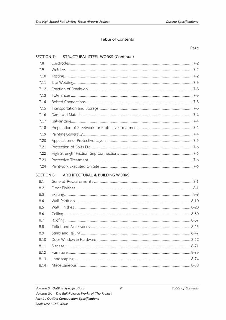
SECTION 7: STRUCTURAL STEEL WORKS (Continue) 7.8 Electrodes .......................................................................................................................................7-2 7.9 Welders ............................................................................................................................................7-2 7.10 Testing ..............................................................................................................................................7-2 7.11 Site Welding....................................................................................................................................7-3 7.12 Erection of Steelwork...................................................................................................................7-3 7.13 Tolerances ......................................................................................................................................7-3 7.14 Bolted Connections ......................................................................................................................7-3 7.15 Transportation and Storage ........................................................................................................7-3 7.16 Damaged Material .........................................................................................................................7-4 7.17 Galvanizing ......................................................................................................................................7-4 7.18 Preparation of Steelwork for Protective Treatment ............................................................7-4 7.19 Painting Generally .........................................................................................................................7-4 7.20 Application of Protective Layers ...............................................................................................7-5 7.21 Protection of Bolts Etc. ...............................................................................................................7-6 7.22 High Strength Friction Grip Connections .................................................................................7-6 7.23 Protective Treatment ...................................................................................................................7-6 7.24 Paintwork Executed On Site .......................................................................................................7-6
SECTION 8: ARCHITECTURAL & BUILDING WORKS 8.1 General Requirements .............................................................................................................8-1 8.2 Floor Finishes .................................................................................................................................8-1 8.3 Skirting ..............................................................................................................................................8-9 8.4 Wall Partition ............................................................................................................................... 8-10 8.5 Wall Finishes ............................................................................................................................... 8-20 8.6 Ceiling............................................................................................................................................ 8-30 8.7 Roofing .......................................................................................................................................... 8-37 8.8 Toilet and Accessories .............................................................................................................. 8-45 8.9 Stairs and Railing ........................................................................................................................ 8-47 8.10 Door-Window & Hardware ....................................................................................................... 8-52 8.11 Signage .......................................................................................................................................... 8-71 8.12 Furniture ...................................................................................................................................... 8-73 8.13 Landscaping ................................................................................................................................ 8-74 8.14 Miscellaneous ............................................................................................................................ 8-88
The High Speed Rail Linking Three Airports Project Outline Specifications
Volume 3 : Outline Specifications iv Table of Contents Volume 3/1 : The Rail-Related Works of The Project Part 2 : Outline Construction Specifications Book 1//2 : Civil Works
Table of Contents
Page
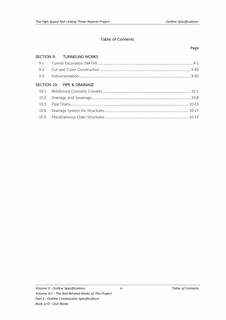
SECTION 9: TUNNELING WORKS 9.1 Tunnel Excavation (NATM) .........................................................................................................9-1 9.2 Cut and Cover Construction ................................................................................................... 9-45 9.3 Instrumentation .......................................................................................................................... 9-50
SECTION 10: PIPE & DRAINAGE 10.1 Reinforced Concrete Culverts ................................................................................................. 10-1 10.2 Drainage and Sewerage ............................................................................................................ 10-8 10.3 Pipe Drains ................................................................................................................................. 10-13 10.4 Drainage System for Structures ............................................................................................ 10-17 10.5 Miscellaneous Drain Structures ............................................................................................ 10-19
The High Speed Rail Linking Three Airports Project Outline Construction Specifications
Volume 3 : Outline Specifications 1-1 Section 1: Standards Volume 3/1 : The Rail-Related Works of The Project Part 2 : Outline Construction Specifications Book 1//2 : Civil Works
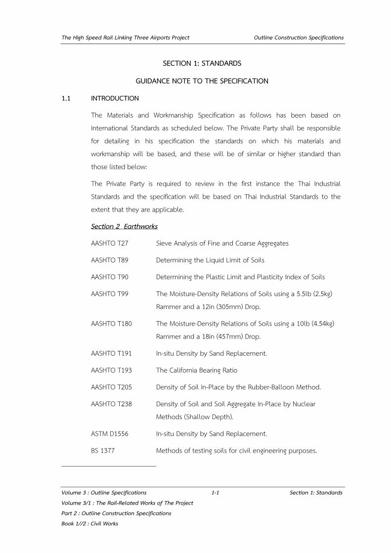
SECTION 1: STANDARDS
GUIDANCE NOTE TO THE SPECIFICATION
1.1 INTRODUCTION
The Materials and Workmanship Specification as follows has been based on International Standards as scheduled below. The Private Party shall be responsible for detailing in his specification the standards on which his materials and workmanship will be based, and these will be of similar or higher standard than those listed below:
The Private Party is required to review in the first instance the Thai Industrial Standards and the specification will be based on Thai Industrial Standards to the extent that they are applicable.
Section 2 Earthworks
AASHTO T27 Sieve Analysis of Fine and Coarse Aggregates
AASHTO T89 Determining the Liquid Limit of Soils
AASHTO T90 Determining the Plastic Limit and Plasticity Index of Soils
AASHTO T99 The Moisture-Density Relations of Soils using a 5.5lb (2.5kg) Rammer and a 12in (305mm) Drop.
AASHTO T180 The Moisture-Density Relations of Soils using a 10lb (4.54kg) Rammer and a 18in (457mm) Drop.
AASHTO T191 In-situ Density by Sand Replacement.
AASHTO T193 The California Bearing Ratio
AASHTO T205 Density of Soil In-Place by the Rubber-Balloon Method.
AASHTO T238 Density of Soil and Soil Aggregate In-Place by Nuclear Methods (Shallow Depth).
ASTM D1556 In-situ Density by Sand Replacement.
BS 1377 Methods of testing soils for civil engineering purposes.
The High Speed Rail Linking Three Airports Project Outline Construction Specifications
Volume 3 : Outline Specifications 1-2 Section 1: Standards Volume 3/1 : The Rail-Related Works of The Project Part 2 : Outline Construction Specifications Book 1//2 : Civil Works
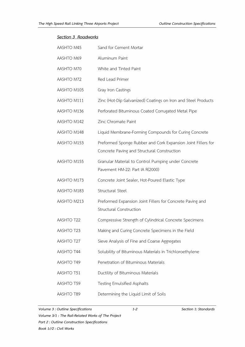
Section 3 Roadworks
AASHTO M45 Sand for Cement Mortar
AASHTO M69 Aluminum Paint
AASHTO M70 White and Tinted Paint
AASHTO M72 Red Lead Primer
AASHTO M105 Gray Iron Castings
AASHTO M111 Zinc (Hot-Dip Galvanized) Coatings on Iron and Steel Products
AASHTO M136 Perforated Bituminous Coated Corrugated Metal Pipe
AASHTO M142 Zinc Chromate Paint
AASHTO M148 Liquid Membrane-Forming Compounds for Curing Concrete
AASHTO M153 Preformed Sponge Rubber and Cork Expansion Joint Fillers for Concrete Paving and Structural Construction
AASHTO M155 Granular Material to Control Pumping under Concrete Pavement HM-22: Part IA R(2000)
AASHTO M173 Concrete Joint Sealer, Hot-Poured Elastic Type
AASHTO M183 Structural Steel
AASHTO M213 Preformed Expansion Joint Fillers for Concrete Paving and Structural Construction
AASHTO T22 Compressive Strength of Cylindrical Concrete Specimens
AASHTO T23 Making and Curing Concrete Specimens in the Field
AASHTO T27 Sieve Analysis of Fine and Coarse Aggregates
AASHTO T44 Solubility of Bituminous Materials in Trichloroethylene
AASHTO T49 Penetration of Bituminous Materials
AASHTO T51 Ductility of Bituminous Materials
AASHTO T59 Testing Emulsified Asphalts
AASHTO T89 Determining the Liquid Limit of Soils
The High Speed Rail Linking Three Airports Project Outline Construction Specifications
Volume 3 : Outline Specifications 1-3 Section 1: Standards Volume 3/1 : The Rail-Related Works of The Project Part 2 : Outline Construction Specifications Book 1//2 : Civil Works
AASHTO T90 Determining the Plastic Limit and Plasticity Index of Soils
AASHTO T96 Resistance to Degradation of Small-Size Coarse Aggregate by Abrasion and Impact in the Los Angeles Machine
AASHTO T104 Soundness of Aggregate by Use of Sodium Sulfate or Magnesium Sulfate
AASHTO T119 Slump of Hydraulic Cement Concrete
AASHTO T164 Quantitative Extraction of Bitumen from Bituminous Paving Mixtures
AASHTO T170 Recovery of Asphalt from Solution by Abson Method
AASHTO T176 Plastic Fines in Graded Aggregates and Soils by Use of the Sand Equivalent Test
AASHTO T180 Moisture-Density Relations of Soils using a 4.5 kg (10 lb) Rammer and a 457 mm (18-in) Drop
AASHTO T182 Coating and Stripping of Bitumen-Aggregate Mixtures
AASHTO T191 Density of Soil In-Place by the Sand-Cone Method
AASHTO T193 The California Bearing Ratio
AASHTO T200 pH of Aqueous Solutions with the Glass Electrode
ASTM A48 Standard Specification for Gray Iron Castings
ASTM A276 Standard Specification for Stainless Steel Bars and Shapes
ASTM A536 Standard Specification for Ductile Iron Castings
ASTM A653 Standard Specification for Steel Sheet, Zinc-Coated (Galvanized) or Zinc-Iron Alloy-Coated (Galvannealed) by the Hot-Dip Process
ASTM B148 Standard Specification for Aluminum-Bronze Sand Castings
ASTM B209 Standard Specification for Aluminum and Aluminum-Alloy Sheet and Plate
ASTM D4 Standard Test Method for Bitumen Content
The High Speed Rail Linking Three Airports Project Outline Construction Specifications
Volume 3 : Outline Specifications 1-4 Section 1: Standards Volume 3/1 : The Rail-Related Works of The Project Part 2 : Outline Construction Specifications Book 1//2 : Civil Works
ASTM D5 Standard Test Method for Penetration of Bituminous Materials
ASTM D113 Standard Test Method for Ductility of Bituminous Materials
ASTM D244 Standard Test Method and Practices for Emulsified Asphalts
ASTM D2042 Standard Test Method for Solubility of Asphalt Materials in Trichloroethylene
ASTM E70 Standard Test Method for pH of Aqueous Solutions with the Glass Electrode
BS 812 Testing Aggregates
BS 892 Glossary of Highway Engineering Terms (S/S, W/D)
BS 1470 Specification for Wrought Aluminum and Aluminum Alloys for General Engineering Purposes: Plate, Sheet and Strip
BS 1788 Street Lighting Lanterns
BS CP 1004 Street Lighting
TIS 15 Portland Cement
TIS 20 Steel Bars for Reinforced Concrete : Round Bars
TIS 24 Steel Bars for Reinforced Concrete : Deformed Bars
TIS 55 Flat and Square Steel Bars
TIS 248 Corrugated Sheet Steel Beams for Highway Guardrail
TIS 371 Cationic Asphalt Emulsion for Road
TIS 536 Grey Cast Iron
TIS 542 Thermoplastic Road Marking Materials
TIS 606 Reflective Sheeting
TIS 826 Cement Mortar Flooring Tiles
TIS 827 Interlocking Concrete Paving Blocks
TIS 851 Asphalt Cement for Use in Pavement Construction
TIS 865 Cut-Back Asphalt
The High Speed Rail Linking Three Airports Project Outline Construction Specifications
Volume 3 : Outline Specifications 1-5 Section 1: Standards Volume 3/1 : The Rail-Related Works of The Project Part 2 : Outline Construction Specifications Book 1//2 : Civil Works
BMA Standards "Standards and Specifications for BMA's Traffic Signs"
BMA Standards “Standards for Road Markings”
DOH standards “Manual of Road Markings”
DOH standards “Manual of Traffic Signs” and “Standards of Sign Boards”
Department of Highways Specifications for Highway Construction.
DH-S Standard for Highway Construction
DH-T Standard Testing
DH-SP Specification for Materials
Section 4 Piling & Diaphragm Walling
TIS 395 Standard for Precast Reinforced Concrete Piles
TIS 399 Standard for Precast Reinforced Concrete Short Piles
TIS 397 Standard for Precast Reinforced Spun Concrete Piles
TIS 396 Standard for Prestressed Concrete Piles
TIS 398 Standard for Prestressed Spun Concrete Piles
AASHTO Standard Spec. for Highway Bridges
ASTM D4945 Test Method for High Strain Dynamic Testing of Piles
ASTM D1143 Test Method for Piles Under Static Axial Compression Load
ASTM D3689 Test Method of Testing Individual Piles Under Static Axial Tensile Load
ASTM D3966 Method of Testing Piles Under Lateral Loads
BS 8004 Code of Practice for Foundations
ACI-543 R-74 (80) Recommendation for Design, Manufacture and Installation of Concrete Piles
ACI 336-1-89 Standard Specification for the Construction of Drilled Piers
The High Speed Rail Linking Three Airports Project Outline Construction Specifications
Volume 3 : Outline Specifications 1-6 Section 1: Standards Volume 3/1 : The Rail-Related Works of The Project Part 2 : Outline Construction Specifications Book 1//2 : Civil Works
Section 5 Concrete
TIS 15 Portland Cement.
TIS 20 Reinforcing bar, Round Bar.
TIS 24 High Yield Deformed Bars.
TIS 138 Standard of Binding Wire.
AASHTO Standard Specification for Highway Bridges
AASHTO M6 Fine Aggregate.
AASHTO M80 Coarse Aggregate.
AASHTO M194 Admixtures.
AASHTO T26 Quality of Water to be used in Concrete.
ACI 305 Recommendations for Hot Weather Concreting.
ASTM C39 Method of Test for Compressive Strength of Moulded Concrete
Cylinders.
ASTM C232 Method of Test for Bleeding of Concrete.
BS 639 Covered carbon and carbon manganese steel electrodes for metal- arc welding.
BS 812 Testing Aggregates.
BS 882 Aggregates from natural sources for concrete.
BS 1014 Pigments for Portland cement and Portland cement products.
BS 1610 Materials testing machines and force verification equipment. BS 1881 Methods of testing concrete.
BS 3148 Water for making concrete.
BS 3797 Lightweight aggregates for concrete.
BS 4466 Scheduling, dimensioning, bending and cutting for steel reinforcement for concrete.
The High Speed Rail Linking Three Airports Project Outline Construction Specifications
Volume 3 : Outline Specifications 1-7 Section 1: Standards Volume 3/1 : The Rail-Related Works of The Project Part 2 : Outline Construction Specifications Book 1//2 : Civil Works
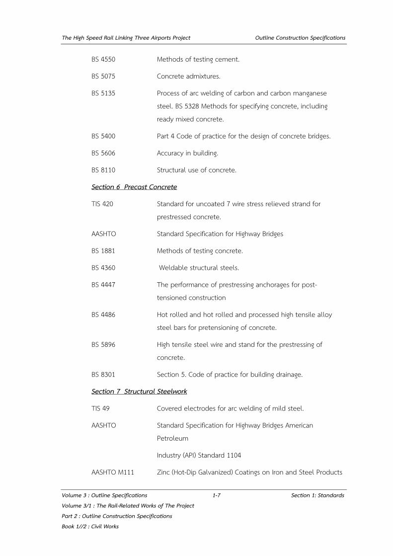
BS 4550 Methods of testing cement.
BS 5075 Concrete admixtures.
BS 5135 Process of arc welding of carbon and carbon manganese steel. BS 5328 Methods for specifying concrete, including ready mixed concrete.
BS 5400 Part 4 Code of practice for the design of concrete bridges.
BS 5606 Accuracy in building.
BS 8110 Structural use of concrete.
Section 6 Precast Concrete
TIS 420 Standard for uncoated 7 wire stress relieved strand for prestressed concrete.
AASHTO Standard Specification for Highway Bridges
BS 1881 Methods of testing concrete.
BS 4360 Weldable structural steels.
BS 4447 The performance of prestressing anchorages for post-tensioned construction
BS 4486 Hot rolled and hot rolled and processed high tensile alloy steel bars for pretensioning of concrete.
BS 5896 High tensile steel wire and stand for the prestressing of concrete.
BS 8301 Section 5. Code of practice for building drainage.
Section 7 Structural Steelwork
TIS 49 Covered electrodes for arc welding of mild steel.
AASHTO Standard Specification for Highway Bridges American Petroleum
Industry (API) Standard 1104
AASHTO M111 Zinc (Hot-Dip Galvanized) Coatings on Iron and Steel Products

The High Speed Rail Linking Three Airports Project Outline Construction Specifications
Volume 3 : Outline Specifications 1-8 Section 1: Standards Volume 3/1 : The Rail-Related Works of The Project Part 2 : Outline Construction Specifications Book 1//2 : Civil Works
AASHTO M164 High-Strength Bolts for Structural Steel Joints
ASTM A6 Standard Specification for General Requirements for Rolled Structural Steel Bars, Plates, Shapes, and Sheet Piling
ASTM A36 Standard Specification for Carbon Structural Steel
ASTM A123 Standard Specification for Zinc (Hot-Dip Galvanized) Coatings on Iron and Steel Products
ASTM A153 Standard Specification for Zinc (Hot-Dip) on Iron and Steel Hardware
ASTM A307 Standard Specification for Carbon Steel Bolts and Studs, 60000 PSI Tensile Strength
ASTM A320 Standard Specification for Alloy-Steel and Stainless Steel Bolting Materials for Low-Temperature Service
ASTM A325 Standard Specification for Structural Bolts, Steel, Heat-Treated, 120/105 ksi Minimum Tensile Strength
ASTM A490 Standard Specification for Structural Bolts, Alloy Steel, Heat- Treated, 150 ksi Minimum Tensile Strength
ASTM A500 Standard Specification for Cold-Formed Welded and Seamless Carbon Steel Structural Tubing in Rounds and Shapes
ASTM A501 Standard Specification for Hot-Formed Welded and Seamless Carbon Steel Structural Tubing
ASTM A666 Standard Specification for Annealed or Cold-Worked Austenitic Stainless Steel Sheet, Strip, Plate, and Flat Bar
ASTM B695 Standard Specification for Coatings of Zinc Mechanically Deposited on Iron and Steel
ASTM E165 Standard Test Method for Liquid Penetrant Examination
AWS D1.1 Structural Welding Code - Steel
BS 639 Covered carbon and carbon manganese steel electrodes for manual arc-welding.
The High Speed Rail Linking Three Airports Project Outline Construction Specifications
Volume 3 : Outline Specifications 1-9 Section 1: Standards Volume 3/1 : The Rail-Related Works of The Project Part 2 : Outline Construction Specifications Book 1//2 : Civil Works
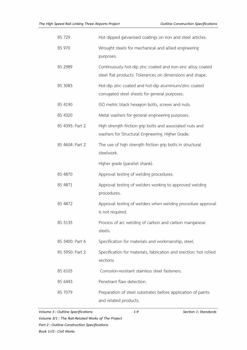
BS 729 Hot dipped galvanised coatings on iron and steel articles.
BS 970 Wrought steels for mechanical and allied engineering purposes.
BS 2989 Continuously hot-dip zinc coated and iron-zinc alloy coated steel flat products: Tolerances on dimensions and shape.
BS 3083 Hot-dip zinc coated and hot-dip aluminium/zinc coated corrugated steel sheets for general purposes.
BS 4190 ISO metric black hexagon bolts, screws and nuts.
BS 4320 Metal washers for general engineering purposes.
BS 4395: Part 2 High strength friction grip bolts and associated nuts and washers for Structural Engineering. Higher Grade.
BS 4604: Part 2 The use of high strength friction grip bolts in structural steelwork.
Higher grade (parallel shank).
BS 4870 Approval testing of welding procedures.
BS 4871 Approval testing of welders working to approved welding procedures.
BS 4872 Approval testing of welders when welding procedure approval is not required.
BS 5135 Process of arc welding of carbon and carbon manganese steels.
BS 5400: Part 6 Specification for materials and workmanship, steel.
BS 5950: Part 2 Specification for materials, fabrication and erection: hot rolled sections
BS 6105 Corrosion-resistant stainless steel fasteners.
BS 6443 Penetrant flaw detection.
BS 7079 Preparation of steel substrates before application of paints and related products.

The High Speed Rail Linking Three Airports Project Outline Construction Specifications
Volume 3 : Outline Specifications 1-10 Section 1: Standards Volume 3/1 : The Rail-Related Works of The Project Part 2 : Outline Construction Specifications Book 1//2 : Civil Works
Section 8 Architectural and Building Works
NFPA 101 Life safety code
NFPA 130 Standard for fixed guideway transit and passenger rail systems
NFPA 220 Standard on types of building construction
LUL E1042:A4 Engineering standard for the fire safety performance of materials used underground
ASTM C 39 Standard test method for compressive strength of cylindrical concrete specimens
ASTM C 232 Standard test methods for bleeding of concrete
BS 405 Specification for uncoated expanded metal carbon steel sheets for general purposes
BS 416: Part 1 Discharge and ventilating pipes and fittings, sand-cast or spun in cast iron. Specification for spigot and socket systems.
BS 460 Cast iron rainwater goods. Specification.
BS 476: Part 3 Fire tests on building materials and structures. Classification and method of test for external fire exposure to roofs
BS 476: Part 6 Fire tests on building materials and structures. Method of test for fire propagation for products
BS 476: Part 7 Fire tests on building materials and structures. Method of test to determine the classification of the surface spread of flame of products
BS 476: Part 20 Fire tests on building materials and structures. Method for determination of the fire resistance of elements of construction (general principles)
BS 476: Part 22 Fire tests on building materials and structures. Methods for determination of the fire resistance of non-loadbearing elements of construction.
BS 812 Testing aggregates. Guide to sampling and testing aggregates. BS 890 Specification for building limes
The High Speed Rail Linking Three Airports Project Outline Construction Specifications
Volume 3 : Outline Specifications 1-11 Section 1: Standards Volume 3/1 : The Rail-Related Works of The Project Part 2 : Outline Construction Specifications Book 1//2 : Civil Works
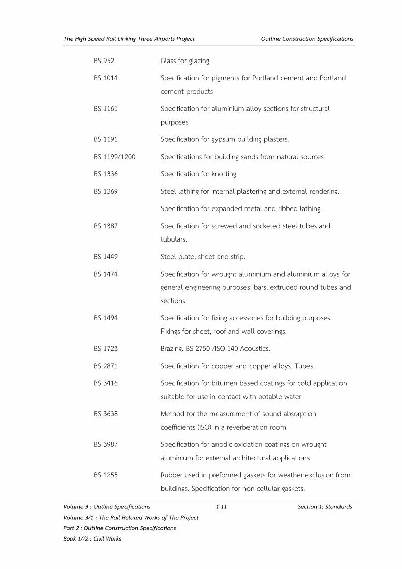
BS 952 Glass for glazing
BS 1014 Specification for pigments for Portland cement and Portland cement products
BS 1161 Specification for aluminium alloy sections for structural purposes
BS 1191 Specification for gypsum building plasters.
BS 1199/1200 Specifications for building sands from natural sources
BS 1336 Specification for knotting
BS 1369 Steel lathing for internal plastering and external rendering.
Specification for expanded metal and ribbed lathing.
BS 1387 Specification for screwed and socketed steel tubes and tubulars.
BS 1449 Steel plate, sheet and strip.
BS 1474 Specification for wrought aluminium and aluminium alloys for general engineering purposes: bars, extruded round tubes and sections
BS 1494 Specification for fixing accessories for building purposes. Fixings for sheet, roof and wall coverings.
BS 1723 Brazing. BS-2750 /ISO 140 Acoustics.
BS 2871 Specification for copper and copper alloys. Tubes.
BS 3416 Specification for bitumen based coatings for cold application, suitable for use in contact with potable water
BS 3638 Method for the measurement of sound absorption coefficients (ISO) in a reverberation room
BS 3987 Specification for anodic oxidation coatings on wrought aluminium for external architectural applications
BS 4255 Rubber used in preformed gaskets for weather exclusion from buildings. Specification for non-cellular gaskets.

The High Speed Rail Linking Three Airports Project Outline Construction Specifications
Volume 3 : Outline Specifications 1-12 Section 1: Standards Volume 3/1 : The Rail-Related Works of The Project Part 2 : Outline Construction Specifications Book 1//2 : Civil Works
BS 4641 Method for specifying electroplated coatings of chromium for engineering purposes
BS 4772 Specification for ductile iron pipes and fittings
BS 4800 Schedule of paint colours for building purposes
BS 4887 Specification for mortar plasticizers
BS 4921 Specification for sherardized coatings on iron and steel
BS 5385 Wall and floor tiling, code of practice for the design and installation of terrazzo tile and slab, natural stone and composition block floorings
BS 5427: Part 1 Code of practice for the use of profiled sheet for roof and wall cladding on buildings.
BS 5628 Code of Practice for use of masonry, Materials and components, design and workmanship
BS 5810 Code of practice for access for the disabled to buildings
BS 5980 Specification for adhesives for use with ceramic tiles and mosaics
BS 6180 Barriers in and about buildings. Code of practice.
BS 6202 Specification for impact performance requirements for flat safety glass and safety plastics for use in buildings
BS 6213 Selection of construction sealants. Guide.
BS 6229 Flat roofs with continuously supported coverings. Code of practice.
BS 6262 Glazing for buildings.
BS 6399 Loading for buildings
BS 6431 Ceramic floor and wall tiles. Specification for classification and marking, including definitions and characteristics.
BS 6459: Part 1 Door closers. Specification for mechanical performance of crank and rack and pinion overhead closers.

The High Speed Rail Linking Three Airports Project Outline Construction Specifications
Volume 3 : Outline Specifications 1-13 Section 1: Standards Volume 3/1 : The Rail-Related Works of The Project Part 2 : Outline Construction Specifications Book 1//2 : Civil Works
BS 6477 Specification for water repellents for masonry surfaces
BS 6496 Specification for powder organic coatings for application and stoving to aluminium alloy extrusions, sheet and preformed sections for external architectural purposes, and for the finish on aluminium alloy extrusions, sheet and preformed sections coated with powder organic coatings
BS 7352 Specification for strength and durability performance of metal hinges for side hanging applications and dimensional requirements for template drilled hinges.
BS 7668 Weldable structural steels. Hot finished structural hollow sections in weather resistant steels. Specification.
BS 8204: Part 1 Screeds, bases and in-situ floorings. Code of practice for concrete bases and screeds to receive in-situ floorings.
BS 8217 Reinforced bitumen membranes for roofing. Code of practice.
BS 8218 Code of practice for mastic asphalt roofing.
BS 8290 Suspended ceilings.
BS 8298 Code of practice for design and installation of natural stone cladding and lining
BS EN 485:pts 1-4 Aluminium and aluminium alloys. Sheet, strip and plate.
BS EN 515 Aluminium and aluminium alloys. Wrought products.
BS EN 573 Aluminium and aluminium alloys. Chemical composition and form of wrought products.
BS EN 1125 Building hardware. Panic exit devices operated by a horizontal bar.
Requirements and test methods.
BS EN ISO 1461 Hot dip galvanized coatings on iron and steel articles. Specifications and Methods
BS EN 10029 Specifications for tolerances on dimensions, shape and mass for hot rolled steel plates 3mm thick or above.
The High Speed Rail Linking Three Airports Project Outline Construction Specifications
Volume 3 : Outline Specifications 1-14 Section 1: Standards Volume 3/1 : The Rail-Related Works of The Project Part 2 : Outline Construction Specifications Book 1//2 : Civil Works
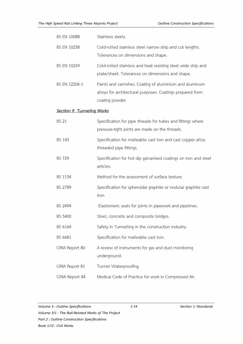
BS EN 10088 Stainless steels.
BS EN 10258 Cold-rolled stainless steel narrow strip and cut lengths. Tolerances on dimensions and shape.
BS EN 10259 Cold-rolled stainless and heat resisting steel wide strip and plate/sheet. Tolerances on dimensions and shape.
BS EN 12206-1 Paints and varnishes. Coating of aluminium and aluminum alloys for architectural purposes. Coatings prepared from coating powder.
Section 9 Tunneling Works
BS 21 Specification for pipe threads for tubes and fittings where pressure-tight joints are made on the threads.
BS 143 Specification for malleable cast iron and cast copper alloy threaded pipe fittings.
BS 729 Specification for hot dip galvanised coatings on iron and steel articles.
BS 1134 Method for the assessment of surface texture.
BS 2789 Specification for spheroidal graphite or nodular graphite cast iron.
BS 2494 Elastomeric seals for joints in pipework and pipelines.
BS 5400 Steel, concrete and composite bridges.
BS 6164 Safety in Tunnelling in the construction industry.
BS 6681 Specification for malleable cast iron.
CIRIA Report 80 A review of instruments for gas and dust monitoring underground.
CIRIA Report 81 Tunnel VVaterproofing.
ClRiA Report 44 Medicai Code of Practice for work in Compressed Air.

The High Speed Rail Linking Three Airports Project Outline Construction Specifications
Volume 3 : Outline Specifications 1-15 Section 1: Standards Volume 3/1 : The Rail-Related Works of The Project Part 2 : Outline Construction Specifications Book 1//2 : Civil Works
Design Standards for Railway Structures and Commentary (Cut and Cover Tunnel), Railway Technical Research Institute, Japan (RTRI-J)
Standard Specifications for Tunnelling - 2006 : Cut and Cover, Japan Society of Civil Engineers (JSCE)ASTM C1436 Standard Specification for Materials for Shotcrete
ACI 506.2-13 Specification for Shotcrete
Section 10 Pipe & Drainage
ASTM A53 Standard Specification for Pipe, Steel, Black and Hot-Dipped, Zinc-Coated, Welded and Seamless
AASHTO M86 Concrete Sewer, Storm Drain, and Culvert Pipe
AASHTO M170 Reinforced Concrete Culvert, Storm Drain and Sewer Pipe
AASHTO M175 Standard Strength Perforated Non-Reinforced Concrete Underdrainage Pipe
AASHTO T33 Concrete Pipe, Sections or Tile
TIS 128 Precast Reinforced Concrete Drainage Pipe
TIS 17 Unplasticized Polyvinyl Chloride Pipes for Drinking Water Services
TIS 277 Galvanized Steel Pipes
TIS 982 High-Density Polyethylene Pipes for Drinking Water Services BMA Standards "Introduction to the method of co-ordination and action relating to the excavation and repairing of BMA roads between utility authorities and BMA"
The High Speed Rail Linking Three Airports Project Outline Construction Specifications
Volume 3 : Outline Specifications 2-1 Section 2: Earthworks Volume 3/1 : The Rail-Related Works of The Project Part 2 : Outline Construction Specifications Book 1//2 : Civil Works
SECTION 2: EARTHWORKS
2.1 EXCAVATION
2.1.1 Site Clearance
The Private Party shall clear the Site as required by demolishing and removing vegetation, debris, trees, buildings etc. and the like to approved locations either on or off the site as agreed by the Engineer’s Representative.
Stumps and major roots shall be grubbed up and disposed of off the site or burnt as directed. The Private Party shall take precautions to prevent the spread of fire to adjacent land.
2.1.2 Top Soil Stripping
Top soil shall be removed as required, deposited in separate heaps for re-use and kept free of weeds.
2.1.3 Removal of Unsuitable Material
The Private Party shall remove unsuitable material as ordered or agreed by the Engineer’s Representative and shall dispose of it on or off the site as directed.
2.1.4 Excavation - General
(1) Excavation shall be carried out to the lines, levels and profiles shown on the Working Drawings or to such other lines, levels and profiles as the Engineer’s Representative may consent to in writing. The work shall be carried out by the Private Party in such a way as to avoid disturbance to the surrounding ground. Particular care shall be taken to maintain stability when excavating in close proximity to existing works.
(2) The work shall be carried out in a careful manner to ensure that the exposed surfaces are as sound as the nature of the material permits and that no point shall protrude inside the lines shown on the Working Drawings except as otherwise specified or consented to by the Engineer’s Representative. In soft excavation which is to remain open permanently, exposed faces shall be formed accurately to the required slopes and profiles.
(3) The Private Party shall dispose of all material arising from excavations either off the site or to approved tips on the site, as required.

The High Speed Rail Linking Three Airports Project Outline Construction Specifications
Volume 3 : Outline Specifications 2-2 Section 2: Earthworks Volume 3/1 : The Rail-Related Works of The Project Part 2 : Outline Construction Specifications Book 1//2 : Civil Works
2.1.5 Excavation Beyond True Lines and Levels
If from any cause whatsoever excavations are carried out beyond their true line and level other than on the instructions of the Engineer’s Representative, the Private Party at his own expense shall make good to the required line and level with the appropriate grade of filling to be contained in the true excavation, or with concrete or other approved material in such a manner as the Engineer’s Representative may consented to.
2.1.6 Inspection of Excavation
When excavations have been taken out accurately to the profiles or dimensions required for the work, the Private Party shall inform the Engineer’s Representative so that he may carry out an inspection.
If, after his inspection the Engineer’s Representative requires additional excavation to be carried out, the Private Party shall do so to such new profiles or dimensions as the Engineer’s Representative may consent to.
2.1.7 Excavations for Foundations
(1) Open excavation to form a foundation for a structure shall be carried out to the lines necessary to permit the proper construction of the structure as consented to by the Engineer’s Representative.
(2) Where a structure is to be founded on soft ground, the excavation shall be taken down until the required formation is exposed and prepared as consented to by the Engineer’s Representative.
(3) If required, before any concrete for a foundation is placed, the bottom of the excavation shall be re-compacted to achieve a smooth and level surface. Subject to the consent of the Engineer’s Representative, sand layers shall be placed and compacted to 95% of the maximum dry density of AASHTO test method T-180 in layers not exceeding 150mm thick.
(4) Surfaces of excavations or filling which are to receive reinforced concrete work shall, where indicated, be prepared with a blinding layer of concrete or in such other manner as will provide a suitable surface at the correct lines and levels as consented to by the Engineer’s Representative.
The High Speed Rail Linking Three Airports Project Outline Construction Specifications
Volume 3 : Outline Specifications 2-3 Section 2: Earthworks Volume 3/1 : The Rail-Related Works of The Project Part 2 : Outline Construction Specifications Book 1//2 : Civil Works
2.1.8 Trench Excavation
(1) Trench excavation shall be performed by the use of hand tools and approved mechanical equipment, in such manner as to minimize disturbance of the sides and bottom of the excavation.
(2) Trenches for pipes shall be excavated to a sufficient depth and width to enable the pipe and the specified joint, bedding, haunching and surrounding to be accommodated.
2.1.9 Trenches
The Private Party shall carry out excavation in a safe manner such that the sides of the trench are adequately supported and stable.
The Private Party shall leave a clear adequate space between the edge of the excavation and the inner toes of the spoil banks.
Trenches shall be excavated to the lines and levels shown on the Working Drawings.
Trenches shall not be excavated too far in advance of pipe laying and shall be sufficiently wide to allow proper and efficient jointing to be carried out in clean and dry conditions. Due allowance shall be made for bedding and surrounds where these are specified.
The bottoms of all trenches shall be trimmed to grade and level and compacted before any bedding is placed or pipes are laid.
The widths of trenches crossing roads, or at other locations as directed shall be as narrow as is practicably possible. The maximum width measured between undisturbed soil in the trench sides shall not exceed the outside diameter of the pipe being laid plus 550 mm for pipes up to and including 800 mm in diameter and plus 750 mm for pipes over 800 mm in diameter.
Trenches for pipes carrying water under pressure shall, except where otherwise described in the Contract, be excavated to a sufficient depth to ensure a minimum cover of 900 mm to the top of the pipes.

The High Speed Rail Linking Three Airports Project Outline Construction Specifications
Volume 3 : Outline Specifications 2-4 Section 2: Earthworks Volume 3/1 : The Rail-Related Works of The Project Part 2 : Outline Construction Specifications Book 1//2 : Civil Works
2.1.10 Excavations in Roads and Footpaths
The Private Party shall close-sheet and adequately support all trenches along or across existing roads or footpaths. Great care shall be taken by the Private Party to ensure that existing roads and services are not damaged by excavations.
2.1.11 Channels
(1) Channels shall be excavated by methods which will not endanger the stability of the side slopes.
(2) Existing channels, which are to be reshaped, cleared and trimmed, shall be cleared of all weeds and growth and the beds graded to the required levels. The sides of channels shall be trimmed to the required slope so as to provide widths not less than those shown on the Working Drawings.
(3) Side banks of channels shall be trimmed to a neat appearance and even surfaces.
(4) Any channels, streams, drains or pipes taking water to or from cultivated land shall be diverted so as to maintain their flow before being moved or broken into. All diversions and their subsequent reinstatement shall be carried out to the consent of the Engineer’s Representative.
(5) The Private Party shall control the rates of filling and draw-down of water in channels so as not to endanger the stability of earthworks.
2.1.12 Approval of Excavations
The Private Party shall obtain approval of excavations prior to placing pavement layers, fill or concrete. The Private Party shall maintain open excavations in an approved condition, and shall rectify the effects of deterioration due to weather.
2.2 FILL
2.2.1 Fill - General
Prior to commencement of filling, the Private Party shall submit in writing to the Engineer’s Representative for approval of his proposals for carrying out the work such that the optimum use may be made of excavated material. The proposals shall include details of the compaction plant and methods for adjusting the moisture content of the material. Filling shall not commence until the proposals and the material intended to be used are consented to by the Engineer’s Representative.

The High Speed Rail Linking Three Airports Project Outline Construction Specifications
Volume 3 : Outline Specifications 2-5 Section 2: Earthworks Volume 3/1 : The Rail-Related Works of The Project Part 2 : Outline Construction Specifications Book 1//2 : Civil Works
2.2.2 Fill Material
Soil aggregates or sand or any materials shall be durable, free of clay lumps and vegetation, obtained from sources approved by the Engineer’s Representative. Lumps, by adhering or cementing, greater than 50 millimeters in size shall be removed or broken and remixed to uniform distribution.
(1) The maximum size shall be not greater than 50 millimeters and portion passing 0.075 millimeter sieve not greater than 40 %, when tested in accordance with AASHTO T11
(2) CBR values shall be not less than 6 percent, when tested in accordance with AASHTO T193 at 95 % of Maximum Dry Density tested in accordance with AASHTO T99.
(3) Swelling shall be not greater than 3 %, when tested in accordance with AASHTO T193 at 95 percent of Maximum Dry Density tested in accordance with AASHTO T99.
The top 1000 mm of the embankment fill shall be compacted to 100% of the maximum dry density tested in accordance with AASHTO T 99, or as indicated on the Working Drawings.
2.2.3 Backfill - General
Except around structures, excavations shall be backfilled with suitable excavated material and/or approved material compacted in layers of 300 mm maximum thickness to achieve a density of at least 95% of the maximum dry density determined in accordance with AASHTO T-99.
2.2.4 Backfill to Structures or Foundations
The Private Party shall not backfill around structures until the structural elements have attained adequate strength and consented by the Engineer’s Representative to proceed has been obtained. Unless otherwise directed, the backfill material shall be selected excavated material, thoroughly compacted in layers not exceeding 200 mm deep to achieve a density of at least 95% of the maximum dry density as determined in accordance with AASHTO T-180. Backfilling must be completed before extracting any temporary sheet piling which supported the sides of the excavation.
The High Speed Rail Linking Three Airports Project Outline Construction Specifications
Volume 3 : Outline Specifications 2-6 Section 2: Earthworks Volume 3/1 : The Rail-Related Works of The Project Part 2 : Outline Construction Specifications Book 1//2 : Civil Works
2.2.5 Preparation of Foundation for Embankment
(a) Prior to placing any embankment upon any area all clearing and grubbing operations shall have been completed in accordance with Clauses 2.1.1 to 2.1.3. Where the height of embankment is 1 meter or less all sod, grass and vegetable matter shall be removed from the ground surface and the top 15 centimeters shall be processed as necessary and compacted to 90% of the maximum dry density as determined by AASHTO Test Method T-180.
(b) Where embankments are to be constructed on slopes, the existing slopes shall be loosened by scarifying or plowing to a depth of not less than 10 centimeters, to ensure a good bond between the embankment and the embankment foundation, or where this is impracticable, steps in vertical and horizontal face shall be cut in the existing slope and the embankment built up in successive layers. Material which has been loosened shall be recompacted simultaneously with the first level of embankment material placed.
(c) Where existing embankments are to be widened or included in new embankment, the slopes of the existing embankment shall be ploughed or scarified to a depth of not less than 10 centimeters or, where this is impracticable, steps in horizontal and vertical faces shall be cut in existing slopes and the embankment built up in successive layers to the level of the old road, before its height is increased.
Existing unpaved roads are to be covered with less than 30 centimeters of fill, excluding pavement, the top of the old road bed shall be scarified and re-compacted with the next layer of the new embankment. The total depth of the scarified and added material shall not exceed the permissible depth of layer.
(d) Embankments in swamps or water shall be constructed by sand embankment. The Private Party shall, when ordered by the Engineer’s Representative, excavate or displace swamp ground and backfill with suitable material. Backfill will be in accordance with the same provisions as for embankment unless otherwise consented to by the Engineer’s Representative.
The High Speed Rail Linking Three Airports Project Outline Construction Specifications
Volume 3 : Outline Specifications 2-7 Section 2: Earthworks Volume 3/1 : The Rail-Related Works of The Project Part 2 : Outline Construction Specifications Book 1//2 : Civil Works
2.2.6 Placing Embankments
Embankments shall be placed in accordance with the following requirements:
(a) General: Except as otherwise required all embankments shall be constructed in layers approximately parallel to the finished grade of the road bed. During construction of embankment, a smooth grade having an adequate crown or super-elevation shall be maintained to provide drainage. Embankments shall be constructed to the required grade, and completed embankments shall correspond to the shape of the typical sections shown on the Working Drawings
(b) Earth Embankment: Earth embankments shall be defined as those principally of material other than rock, and shall be constructed of approved material from designated or other approved sources.
The Private Party shall consider the use of non-woven geotextile materials to separate fill material from weak/fine soils which might adversely affect the long term stability of the embankment/fill.
Except as specified for embankment in swamps, earth embankments shall be constructed in successive layers, for the full width of the cross section and in such lengths as are suited to the compaction and watering methods used. Prior to compaction the layers shall not exceed 20 centimeters in depth unless consent is granted by the Engineer’s Representative.
(c) Placing embankment over swampy ground where new embankment fill overlies existing khlongs, ditches, ponds or other waterways, these shall be filled in exclusively with sand, except where otherwise consented to by the Engineer’s Representative.
Prior to filling, cofferdams shall be made to allow pumping, and the bed shall be left to dry until approved by the Engineer’s Representative for filling.
The work on this project shall be performed in such a manner and at such times as to avoid interruption of or interference with the free flow of water in the khlongs.
The High Speed Rail Linking Three Airports Project Outline Construction Specifications
Volume 3 : Outline Specifications 2-8 Section 2: Earthworks Volume 3/1 : The Rail-Related Works of The Project Part 2 : Outline Construction Specifications Book 1//2 : Civil Works
(d) Preparation of subgrade: The surface of the finished subgrade shall be neat and workmanlike and shall have the required form, super elevation, levels, grades, and cross section. The surface shall be constructed to sufficient accuracy to permit the construction of subsequent layers of material to the thickness, surface tolerance, and compaction specified.
2.2.7 Compaction of Embankments
(a) When necessary each layer, before being compacted, shall be processed as required to bring the moisture content sufficiently close to optimum to make possible its compaction to the required density. The material shall be so worked as to have uniform moisture content through the entire layer.
(b) Each layer of material shall be compacted uniformly by use of adequate and appropriate compaction equipment. The compaction shall be done in a longitudinal direction along the embankment and shall generally begin at the outer edges and progress toward the center in such a manner that each section receives equal compaction effort.
Hauling equipment shall be operated over the full width of each layer in so far as practicable.
(c) The material in the layers down to 30 centimeters below subgrade shall be compacted to not less than 95% of the maximum dry density under carriageways where sandfill is used, and not less than 92% under sidewalks, central reserves and verges where unspecified fill is used. Layers situated more than 30 centimeters below subgrade shall be compacted to not less than 90% of the maximum dry density under carriageways and not less than 90% under sidewalks, central reserves and verges.
The maximum dry density shall be determined by AASHTO Test Method T 99 Method A.
Samples to determine the compaction shall be taken regularly as decided by the Engineer’s Representative. Such density tests shall be made by the Private Party under the supervision of the Engineer’s Representative and carried out according to AASHTO Test Method T 191 where practicable or else by other test method. The compacted layer shall be approved by the Engineer’s Representative before the Private Party may commence a new layer.

The High Speed Rail Linking Three Airports Project Outline Construction Specifications
Volume 3 : Outline Specifications 2-9 Section 2: Earthworks Volume 3/1 : The Rail-Related Works of The Project Part 2 : Outline Construction Specifications Book 1//2 : Civil Works
If the result of any test shows that the density is less than the required density the Private Party shall carry out further compaction to obtain at least the required density. The Private Party shall give the Engineer’s Representative 24 hours notice that an area is ready for testing.
2.3 TESTS
2.3.1 Testing of Fill - General
Classification tests shall be carried out to ensure that true comparisons can be made between in-situ densities, laboratory compaction densities and field trial densities i.e. that variations in properties of materials being used in the tests are not affecting the results. Tests shall be carried out on fill to determine the degree of compaction achieved, at the rate one test for either each 1,200 m³ or each layer whichever is the more frequent. Compacted layers shall not be covered without approval.
The density of individual compacted layers shall be determined by a method detailed in Test 15 of BS 1377 or AASHTO T 191 and ASTM D 1556 as directed.
The in-situ dry dens i ty of fill shall not be less than 95% of the maximum dry density carried out in accordance with AASHTO Test Method T99
2.4 LANDSCAPING
2.4.1 Topsoiling
The Private Party shall obtain topsoil from temporary dumps or approved borrow-pits and shall spread it on level or sloping surfaces, where ordered, to the specified depth.
2.4.2 Grassing
The topsoil shall be lightly and uniformly raked to give a fine tilth up to 30 mm deep.
The surface shall either be seeded or shall be grassed with a local grass with creeping habit, of which the source and variety shall be consented to by the Engineer’s Representative. Grass sprigs shall be planted at 0.3 m x 0.3 m spacings. The grass shall be adequately watered until such time as the grass becomes established.
Should the growth fail to become established for any reason the Private Party shall recultivate and replant grass as necessary at his own cost in accordance with the
The High Speed Rail Linking Three Airports Project Outline Construction Specifications
Volume 3 : Outline Specifications 2-10 Section 2: Earthworks Volume 3/1 : The Rail-Related Works of The Project Part 2 : Outline Construction Specifications Book 1//2 : Civil Works
above specification, for as many times as necessary for the grass to become established. When established between 50 and 75 mm high, the grass shall be topped by cutting to leave between 25 and 50 mm minimum growth and watering shall be continued as necessary until the grass is firmly established to the Engineer’s Representative's satisfaction.
2.4.3 Slopes and Batters
Where a slope is given in the Specification or on the Working Drawings as a ratio of vertical and horizontal components, it shall be understood that the first component is vertical in all cases e.g. a “slope of 1 in 2” will mean 1 vertical in 2 horizontal and a “batter of 4 to 1” will mean 4 vertical to 1 horizontal. This meaning will be attributed to all other terms such as “inclination” and “gradient”.
2.5 SELECTED MATERIAL A
2.5.1 Description
The work shall consist of construction of selected material layer as the layer of Prepared Subgrade on the fill embankment layer or any layer by furnishing, shaping and compacting soil aggregates of proper quality according to the Specifications to the levels and shapes as shown on the Working Drawings. The thickness shall not be less than 600 mm.
2.5.2 Materials
Soil aggregates shall be durable, consist of coarse material mixed with fine material with good bonding property, free of clay and vegetation, obtained from sources approved by the Engineer’s Representative. Lumps, by adhering or cementing, greater than 50 millimeters in size shall be removed or broken and remixed to uniform distribution.
In case that the property is not specified otherwise, the soil aggregates for selected material A layer shall have the following properties.
(1) The maximum size shall be not greater than 50 millimeters and portion passing 0.075 millimeter sieve not greater than 40 percent, when tested in accordance with AASHTO T11
Sand with either of the following properties shall not be used for selected material A.
The High Speed Rail Linking Three Airports Project Outline Construction Specifications
Volume 3 : Outline Specifications 2-11 Section 2: Earthworks Volume 3/1 : The Rail-Related Works of The Project Part 2 : Outline Construction Specifications Book 1//2 : Civil Works
(1.1) The portion passing 0.425 millimeter sieve is greater than 80 percent when tested in accordance with AASHTO T11
(1.2) The portion passing 0.075 millimeter sieve is less than 8 percent or greater than 30 percent when tested in accordance with AASHTO T11
(2) Liquid Limit shall be not greater than 40 percent when tested in accordance with AASHTO T89
(3) Plasticity Index shall be not greater than 20 percent when tested in accordance with AASHTO T90
(4) CBR values shall be not less than 10 percent when tested in accordance with AASHTO T193 at 95 percent of Maximum Dry Density tested in accordance with AASHTO T180
(5) Swelling shall be not greater than 3 percent, when tested in accordance with AASHTO T193 at 95 percent of Maximum Dry Density tested in accordance with AASHTO T180
(6) In case that shale is used, the average Durability Index of both coarse and fine materials shall be not less than 30 percent, when tested in accordance with AASHTO T210
(7) In case that non-plastic material, which portion passing 2.0 millimeter sieve is greater than 90 percent when tested in accordance with AASHTO T11 and passes the quality criteria in items (1) to (6), is used for selected material A, it shall be compacted to uniform density not less than 100 percent of Maximum Dry Density tested in accordance with AASHTO T180
2.5.3 Construction Method
2.5.3.1 Preparation Prior to Construction
(1) Preparation of Materials
Soil aggregates from a source which has passed quality tests and to be used for selected material, and if it is not to be directly placed on the prepared embankment or any layer, shall be stock piled in appropriate quantity.
The area for stock piling shall be approved by the Engineer’s Representative and free from objectionable materials.
The High Speed Rail Linking Three Airports Project Outline Construction Specifications
Volume 3 : Outline Specifications 2-12 Section 2: Earthworks Volume 3/1 : The Rail-Related Works of The Project Part 2 : Outline Construction Specifications Book 1//2 : Civil Works
Loading and transportation of soil aggregates shall be done with care preventing any segregation between coarse and fine materials. In case that there is any segregation during transportation, the soil aggregates shall be road-mixed.
(2) Preparation of Construction Area
Embankment or any layers to support the selected material A shall be shaped and compacted to the lines, levels, grades, dimension, shapes and density.
Prior to placement of the soil aggregates, the Private Party shall prepared readiness in all aspects such as construction equipment and traffic signs related to the construction as approved by the Engineer’s Representative.
2.5.3.2 Construction
After the implementation of Clause 2.5.3.1, the embankment or any layer to support selected material A shall be watered to be uniformly moist. By using appropriate equipment, soil aggregates shall be hauled, placed on the prepared surface, spreaded, shaped, blended and watered to approximately the Optimum Moisture Content of +3%.
After shaping to satisfaction, the layer shall be uniformly compacted by appropriate compactors all over the surface to obtain density according to the Specifications throughout the thickness. The soil aggregates shall be shaped to the lines, levels, grades, dimensions and cross-sections as shown on the Working Drawings. No holes or loose materials are shown on the surface. Where there is any segregation of coarse and fine materials, it shall be corrected by the Private Party.
2.5.3.3 Quality Control during the Construction
Selected material shall be constructed in layers which the thickness of each layer after compaction be not greater than 150 millimeters.
The Private Party may construct the layer with each compacted layer over 150 millimeters but not greater than 200 millimeters. However, list of appropriate equipment and method of operation shall be submitted. An approximate 200-500 meter long test section shall be constructed for quality check. If, during the construction, there are problems related to density of the upper part and lower part of the layer not being conformed to the Specifications, the Engineer’s Representative

The High Speed Rail Linking Three Airports Project Outline Construction Specifications
Volume 3 : Outline Specifications 2-13 Section 2: Earthworks Volume 3/1 : The Rail-Related Works of The Project Part 2 : Outline Construction Specifications Book 1//2 : Civil Works
can reject the embankment construction with layers over 150 millimeters in thickness.
The Engineer’s Representative shall check the quality of material after blending. If in any section the quality is not correct according to the Specifications, the Private Party shall improve the quality material of until it is proper.
2.5.3.4 Field Density Check
The selected material shall be compacted to obtain a uniform dry density not less than 95 percent for soil aggregates and 100 percent for the material in Clause 2.5.2 (7) of Maximum Dry Density of the sample taken from the work site in the field and tested in accordance with AASHTO T99.
Field density tests shall be carried out in accordance with AASHTO T191. One test hole shall be made for about 100 meter interval per one traffic-lane or about 500 square meters.
2.6 SAND DRAINING LAYER
The function performed by the sand draining layer is to permit the water to drain away from the embankment area. The draining layer is obtained by using granular sand taken from quarries indicated by the Engineer’s Representative or accepted by him and spread in a layer not less than 100 mm on the top of the Selected Material and compacted to 100% of the maximum dry density determine in accordance with AASHTO T99.
2.7 SUBBALLAST AND SUBBASE
"Suitable Materials" for subballast or subbase of railway shall conform to the requirements of this Section 2.7.1 and 2.7.2,
2.7.1 Subballast
Materials for subballast shall be crushed rock soil aggregate conform to the requirements in accordance with Section 3.1: Aggregate Base Course. Subballast shall have the properties as described below:
(1) CBR
The bearing strength CBR ≥ 80% test in accordance with AASHTO T191 with compaction 95% of AASHTO T180.
The High Speed Rail Linking Three Airports Project Outline Construction Specifications
Volume 3 : Outline Specifications 2-14 Section 2: Earthworks Volume 3/1 : The Rail-Related Works of The Project Part 2 : Outline Construction Specifications Book 1//2 : Civil Works
(2) Grading
The grading shall conform to grading envelopes A or B in Table 2-6-1. The fraction passing the No. 200 sieve shall be not greater than two thirds of the fraction passing the No.40 sieve.
(3) Plasticity
The portion passing the No.40 sieve shall, if it is plastic, have a liquid limit not greater than 25% and a plasticity index not greater than 6%.
(4) Percentage of Wear
The coarse part of the material sampled and tested in accordance with AASHTO test method T96 shall have a percentage of wear not greater than 40%.
(5) The Sodium Sulfate Soundness loss shall not exceed 9 percent after five cycles, when it is tested in accordance with AASHTO T 104.
2.7.2 Subbase
Materials for subbase shall consist of soil aggregate, which comply with the requirements given below. All materials shall be free of topsoil and all other organic matter. The materials shall consist of sound durable particles, which do not breakdown under compaction or repeated wetting/drying cycles. Subbase shall have the properties as described below:
(1) CBR
The bearing strength CBR ≥ 25% test in accordance with AASHTO T191 with compaction 95% of AASHTO T180
(2) Grading
The grading for subbase of railway or roadway shall conform to grading envelopes A, B, C or D in Table 2-6-1. The fraction passing the No. 200 sieve shall be not greater than two thirds of the fraction passing the No.40 sieve
(3) Plasticity
The portion passing the No.40 sieve shall, if it is plastic, have a liquid limit not greater than 35% and a plasticity index not greater than 11%.
The High Speed Rail Linking Three Airports Project Outline Construction Specifications
Volume 3 : Outline Specifications 2-15 Section 2: Earthworks Volume 3/1 : The Rail-Related Works of The Project Part 2 : Outline Construction Specifications Book 1//2 : Civil Works
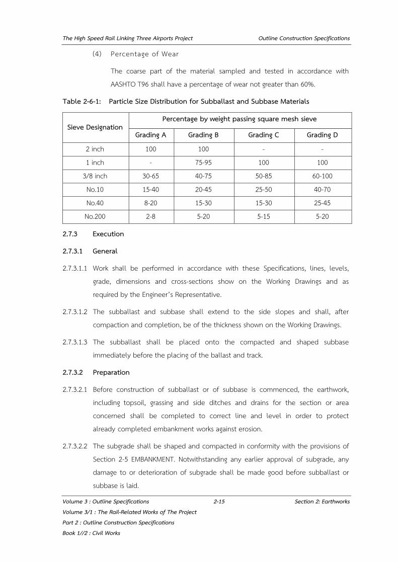
(4) Percentage of Wear
The coarse part of the material sampled and tested in accordance with AASHTO T96 shall have a percentage of wear not greater than 60%.
Table 2-6-1: Particle Size Distribution for Subballast and Subbase Materials
Sieve Designation Percentage by weight passing square mesh sieve
Grading A Grading B Grading C Grading D
2 inch 100 100 - - 1 inch - 75-95 100 100
3/8 inch 30-65 40-75 50-85 60-100 No.10 15-40 20-45 25-50 40-70 No.40 8-20 15-30 15-30 25-45 No.200 2-8 5-20 5-15 5-20
2.7.3 Execution
2.7.3.1 General
2.7.3.1.1 Work shall be performed in accordance with these Specifications, lines, levels, grade, dimensions and cross-sections show on the Working Drawings and as required by the Engineer’s Representative.
2.7.3.1.2 The subballast and subbase shall extend to the side slopes and shall, after compaction and completion, be of the thickness shown on the Working Drawings.
2.7.3.1.3 The subballast shall be placed onto the compacted and shaped subbase immediately before the placing of the ballast and track.
2.7.3.2 Preparation
2.7.3.2.1 Before construction of subballast or of subbase is commenced, the earthwork, including topsoil, grassing and side ditches and drains for the section or area concerned shall be completed to correct line and level in order to protect already completed embankment works against erosion.
2.7.3.2.2 The subgrade shall be shaped and compacted in conformity with the provisions of Section 2-5 EMBANKMENT. Notwithstanding any earlier approval of subgrade, any damage to or deterioration of subgrade shall be made good before subballast or subbase is laid.

The High Speed Rail Linking Three Airports Project Outline Construction Specifications
Volume 3 : Outline Specifications 2-16 Section 2: Earthworks Volume 3/1 : The Rail-Related Works of The Project Part 2 : Outline Construction Specifications Book 1//2 : Civil Works
2.7.3.3 Spreading
Subballast or subbase shall be spread in layers, with uncompacted thickness not exceeding 150 mm subject to the approval of the Engineer’s Representative, and the layers shall be as nearly equal in thickness as possible. Care shall be taken to prevent segregation of the material into fine and coarse parts.
2.7.3.4 Compacting
2.7.3.4.1 Immediately after each layer has been spread and shaped satisfactorily, each layer shall be thoroughly compacted with suitable and adequate compaction equipment approved by the Engineer’s Representative. Rolling operations shall begin from the outer edge of trackbed or roadway toward the centre, gradually in a longitudinal direction; except on super elevated curves, while rolling shall begin at the low side and progress toward the high side.
2.7.3.4.2 During construction of subballast or subbase, the Private Party shall take all necessary precautions to ensure that the layers are efficiently drained.
2.7.3.4.3 The subballast or subbase shall be compacted to at least 95% of the maximum dry density as determined by AASHTO T180. The in-place dry density shall be tested in accordance with AASHTO T191, Density of Soil In-Place by the Sand-Cone Method.
2.7.3.4.4 Material containing excess moisture shall be dried prior to or during compaction to the required moisture content so that proper compaction can be achieved. Drying of wet material shall be performed by methods approved by the Engineer’s Representative, at the expense of the Private Party.
2.7.3.4.5 Material which does not contain sufficient moisture to be compacted, shall have water added to produce the required moisture content so that proper compaction can be achieved.
2.7.3.5 Repair of Defects
2.7.3.5.1 Non complying material shall not be used in the Works and shall be removed from the site.
2.7.3.5.2 The completed thickness of subballast or subbase which is out of the tolerance shall be re-worked to meet the tolerance by the method approved by the Engineer’s Representative.
The High Speed Rail Linking Three Airports Project Outline Construction Specifications
Volume 3 : Outline Specifications 3-1 Section 3: Roadworks Volume 3/1 : The Rail-Related Works of The Project Part 2 : Outline Construction Specifications Book 1//2 : Civil Works
SECTION 3: ROADWORKS
3.1 SUBBASE
3.1.1 Description
This work shall consist of furnishing, placing and compacting subbase material on a prepared and accepted subgrade in accordance with these Specifications, and the lines, levels, grades, dimensions and cross sections as consented to by the SRT’s Representative.
3.1.2 Materials
3.1.2.1 Subbase for Flexible Pavement
Material shall be a soil aggregate material, consist of hard durable particle, free from organic matter, lumps of clay and other deleterious material. The subbase material shall comply with the following requirements.
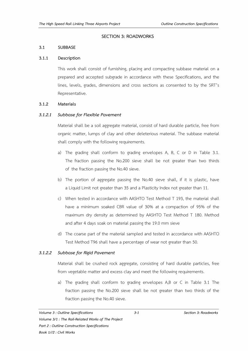
a) The grading shall conform to grading envelopes A, B, C or D in Table 3.1. The fraction passing the No.200 sieve shall be not greater than two thirds of the fraction passing the No.40 sieve.
b) The portion of aggregate passing the No.40 sieve shall, if it is plastic, have a Liquid Limit not greater than 35 and a Plasticity Index not greater than 11.
c) When tested in accordance with AASHTO Test Method T 193, the material shall have a minimum soaked CBR value of 30% at a compaction of 95% of the maximum dry density as determined by AASHTO Test Method T 180. Method and after 4 days soak on material passing the 19.0 mm sieve
d) The coarse part of the material sampled and tested in accordance with AASHTO Test Method T96 shall have a percentage of wear not greater than 50.
3.1.2.2 Subbase for Rigid Pavement
Material shall be crushed rock aggregate, consisting of hard durable particles, free from vegetable matter and excess clay and meet the following requirements.
a) The grading shall conform to grading envelopes A,B or C in Table 3.1 The fraction passing the No.200 sieve shall be not greater than two thirds of the fraction passing the No.40 sieve.
The High Speed Rail Linking Three Airports Project Outline Construction Specifications
Volume 3 : Outline Specifications 3-2 Section 3: Roadworks Volume 3/1 : The Rail-Related Works of The Project Part 2 : Outline Construction Specifications Book 1//2 : Civil Works
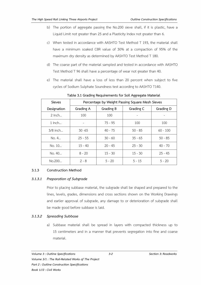
b) The portion of aggregate passing the No.200 sieve shall, if it is plastic, have a Liquid Limit not greater than 25 and a Plasticity Index not greater than 6.
c) When tested in accordance with AASHTO Test Method T 193, the material shall have a minimum soaked CBR value of 30% at a compaction of 95% of the maximum dry density as determined by AASHTO Test Method T 180.
d) The coarse part of the material sampled and tested in accordance with AASHTO Test Method T 96 shall have a percentage of wear not greater than 40.
e) The material shall have a loss of less than 20 percent when subject to five cycles of Sodium Sulphate Soundness test according to AASHTO T140.
Table 3.1 Grading Requirements for Soil Aggregate Material
Sieves Designation
Percentage by Weight Passing Square Mesh Sieves Grading A Grading B Grading C Grading D
2 Inch... 100 100 - -
1 Inch... - 75 - 95 100 100
3/8 inch... 30 -65 40 - 75 50 - 85 60 - 100
No. 4... 25 - 55 30 - 60 35 - 65 50 - 85
No. 10... 15 - 40 20 - 45 25 - 30 40 - 70
No. 40... 8 - 20 15 - 30 15 - 30 25 - 45
No.200... 2 - 8 5 - 20 5 - 15 5 - 20
3.1.3 Construction Method
3.1.3.1 Preparation of Subgrade
Prior to placing subbase material, the subgrade shall be shaped and prepared to the lines, levels, grades, dimensions and cross sections shown on the Working Drawings and earlier approval of subgrade, any damage to or deterioration of subgrade shall be made good before subbase is laid.
3.1.3.2 Spreading Subbase
a) Subbase material shall be spread in layers with compacted thickness up to 15 centimeters and in a manner that prevents segregation into fine and coarse material.

The High Speed Rail Linking Three Airports Project Outline Construction Specifications
Volume 3 : Outline Specifications 3-3 Section 3: Roadworks Volume 3/1 : The Rail-Related Works of The Project Part 2 : Outline Construction Specifications Book 1//2 : Civil Works
b) Subbase material shall contain moisture nearly the optimum moisture content at the time of compaction.
c) Immediately after each layer has been spread and shaped satisfactorily, each layer shall be thoroughly compacted with suitable and adequate compaction equipment. Rolling operations shall begin from the outer edge of roadbed toward the center, gradually in a longitudinal direction; except on super elevated curves, where rolling shall begin at the low side and progress toward the high side.
Each layer shall be compacted to at least 95% of the maximum dry density as determined by AASHTO Test Method T180.
3.1.3.3 Tolerance
The finished subbase at any point shall not vary more than 1.5 centimeters above or below the planned grade or adjusted grade. The subbase completed in each day's work shall have an average thickness not less than the required thickness. Subbase which does not conform to the above requirements shall be reworked by the Private Party.
3.2 AGGREGATE BASE
3.2.1 Description
This work shall consist of construction of a base course of crushed rock to specified grading, placed and compacted on a prepared and accepted subbase or other base course in accordance with these Specifications and to the lines, levels, grades, dimensions and cross sections as consented to by the SRT’s Representative.
3.2.2 Materials
Crushed rock shall consist of hard durable particles or fragments of rock to the required size, and filler of finely divided mineral matter.
a) The grading shall conform with the grading envelope A, B or C in Table 3.1 The fraction passing the No.200 sieve shall be not greater than two thirds of the fraction passing the No.40 sieve.
b) The portion of aggregate passing the No.40 sieve shall, if it is plastic, have a Liquid Limit not more than 25 and a Plasticity Index not more than 6.

The High Speed Rail Linking Three Airports Project Outline Construction Specifications
Volume 3 : Outline Specifications 3-4 Section 3: Roadworks Volume 3/1 : The Rail-Related Works of The Project Part 2 : Outline Construction Specifications Book 1//2 : Civil Works
c) When tested in accordance with AASHTO Test Method T 193, the material shall have a minimum soaked CBR value of 80% at a compaction of 98% of the maximum dry density as determined by AASHTO Test Method T-96.
d) The coarse part of the material sampled and tested in accordance with AASHTO Test Method T-96 shall have a percentage of wear not greater than 40.
3.2.3 Construction Methods
3.2.3.1 Preparation of Subbase
Prior to placing base course material, the subbase shall be shaped and prepared to the lines, levels, grades, dimensions and cross sections as consented to by the SRT’s Representative. Notwithstanding any earlier approval of subbase, any damage to or deterioration of subbase shall be made good before base course is laid.
3.2.3.2 Spreading Base Course
a) Base course shall be spread in layers with compacted thickness up to 15 centimeters and in a manner that prevent segregation into fine and coarse materials.
b) Base course material shall contain moisture nearly the optimum moisture content at the time of compaction.
c) Immediately after each layer has been spread and shaped satisfactorily, each layer shall be thoroughly compacted with suitable and adequate compaction equipment. Rolling operations shall begin from the outer edge of roadbed toward the center, gradually in a longitudinal direction; except on super elevated curves, where rolling shall begin at the low side and progress towards the high side.
The compacted base course shall have an average dry density minimum 98% of the maximum dry density as determined by AASHTO Test Method T 180, no result below 96%.
The High Speed Rail Linking Three Airports Project Outline Construction Specifications
Volume 3 : Outline Specifications 3-5 Section 3: Roadworks Volume 3/1 : The Rail-Related Works of The Project Part 2 : Outline Construction Specifications Book 1//2 : Civil Works
3.2.3.3 Surface Tolerance
In that area on which pavement is to be placed any deviation shall not be in excess of one centimeter from a straight edge 3 meters long applied to the surface parallel to the centerline of the road and 1.25 centimeters from a template laid transversely.
The base course completed in each day's work shall have an average thickness not less than the required thickness. The minimum thickness shall be not less than the
required thickness less 1.5 centimeters. 80% of the base course laid shall have a thickness not less than the required thickness less one centimeter.
Base course which does not conform to the above requirements shall be reworked by the Private Party.
3.3 ASPHALTIC MATERIALS
3.3.1 Description
This section specifies the asphaltic materials to be used in the work.
3.3.2 Materials
The materials shall be of the kind indicated in the Contract Documents. Material shall meet the requirements for one of the following types.
3.3.2.1 Asphalt Cement
Asphalt cement shall conform to the requirements given in Table 3.3.1 and AASHTO Standard Specification for asphalt cement, Grade 60-70, Designation no. M20-63 and/or Thai Industrial Standard, Designation No. TIS 851.
3.3.2.2 Cut back Asphalt
Cut back asphalt shall be of the rapid curing type or the medium curing type and shall conform to the requirements given in Table 3.3.2 and Table 3.3.3 respectively and/or Thai Industrial Standard, Designation no. TIS 865.
3.3.2.3 Emulsified Asphalt
Emulsified asphalt shall be of the anionic type unless the cationic type is explicitly required.

The High Speed Rail Linking Three Airports Project Outline Construction Specifications
Volume 3 : Outline Specifications 3-6 Section 3: Roadworks Volume 3/1 : The Rail-Related Works of The Project Part 2 : Outline Construction Specifications Book 1//2 : Civil Works
Anionic emulsified asphalt shall conform to TIS 371 or the requirements for the appropriate grade, given in Table 3.3.4 and Table 3.3.5 respectively.
3.3.3 Methods of Storage and Handling
Asphaltic material shall be handled and stored with due regard for safety and in such a way that at the time of use in the work the material conforms to the specifications. In particular, emulsified asphalt shall be handled with care and not subjected to mechanical shocks or extremes of temperature likely to cause separation of the asphalt. Emulsified asphalt showing sign of separation shall not be used.
Table 3.3.1 Properties of Asphalt Cement Penetration Grade
Description 40-50 60-70 80-100 120-150 200-300 Min. Max Min. Max Min. Max Min. Max Min. Max Penetration at 25 °C (77 °F) 100 g. 5 sec 40 50 60 70 80 100 120 150 200 300 Flash Point, Cleveland Open Cup F 450 - 450 - 450 - 425 - 350 - Ductility at 25 °C (77 °F) 5 cm per min., cm. 100 - 100 - 100 - 100 - - - Solubility In Trichloroethylene, percent 99 - 99 - 99 - 99 - 99 - Thin-film Oven Test, 1/8 in (3.2 mm). 163 °C (325 °F) 5 hour Loss on Heating, percent - 0.8 - 0.8 - 1.0 - 1.3 - 1.5 Penetration, of residue, percent of original 58 - 54 - 50 - 46 - 40 - Ductility of residue at 25 °C (77 °F) 5 cm per min. cm.
- - 50 - 75 - 100 - 100 -
Spot Test (When and as specified (see 6 Note 1) with): Standard Naphtha Solvent Negative for all grades Naphtha-xylene Solvent, percent xylene Negative for all grades Heptane-xylene Solvent, percent xylene Negative for all grades
Note 1 : The use of the spot test is optional. When it is specified the SRT’s Representatives shall indicate whether the standard naphtha solvent, the naphtha-xylene solvent, or the heptane-xylene solvent will be used in determining compliance with the requirement, and also, in the case of the xylene solvents, the percentage of xylene to be used.

The High Speed Rail Linking Three Airports Project Outline Construction Specifications
Volume 3 : Outline Specifications 3-7 Section 3: Roadworks Volume 3/1 : The Rail-Related Works of The Project Part 2 : Outline Construction Specifications Book 1//2 : Civil Works
Table 3.3.2 Properties of Cut Back Asphalt - Rapid Curing
Description Penetration Grade
RC - 70 RC - 250 RC - 800 RC - 3000 Min. Max. Min. Max. Min. Max. Min. Max.
Kinematic Viscosity at 60°C (140°F) (See Note 1) centistokes
70 140 250 500 800 1600 3000 6000
Flash Point (Tab. Open - Cup). - - 27 - 27 -
degrees C (F) (80) (80)
Water , percent - 0.2 - 0.2 - 0.2 - 0.2
Distillation Test :
Distillate, Percentage by Volume of Total Distillate
to 360°C (680°F)
to 190°C (374°F) 10 - - - - - - -
to 225°C (437°F) 50 - 35 - 15 - - -
to 260°C (500°F) 70 - 60 - 45 - 25 -
to 315°C (600°F) 85 - 80 - 75 - 70 -
Residue from Distillation to 360°C (680°F)
Volume Percentage of Sample by Difference 55 - 65 - 75 - 80 -
Tests on Residue from Distillation
Penetration, 100 g., 5 sec. at 25°C (77°F) 80 120 80 120 80 120 80 120
Ductility, 5 cm./min., cm. at 25°C (77°F) cm 100 - 100 - 100 - 100
Solubility in Trichloroethylene, percent 99 - 99 - 99 - 99
Spot Test (Sec Note 2) with standard Naphtha Negative for all grades
Naphtha -xylene Solvent, percent xylene Negative for all grades
Heptane-xylene Solvent, percent xylene Negative for all grades
Note 1 As an alternate, Saybolt - Furol viscosities may be specified as follows : Grade RC-70 - Furol Viscosity at 50ºC (122ºF) - 60 to 120 sec.
Grade RC-250 - Furol Viscosity at 60ºC (140ºF) - 125 to 250 sec.
Grade RC-800 - Furol Viscosity at 82.2°C (180°F) - 100 to 200 sec.
Grade RC-3000 - Furol Viscosity at 82.2°C (180°F) - 300 to 600 sec.
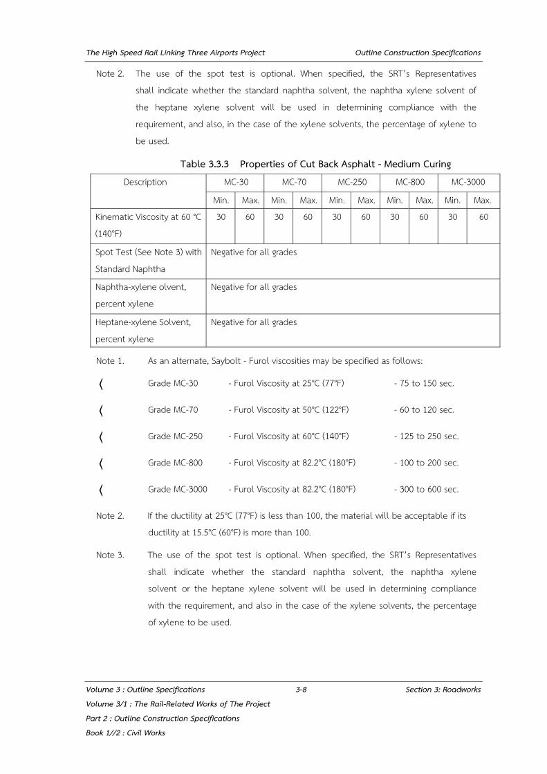
The High Speed Rail Linking Three Airports Project Outline Construction Specifications
Volume 3 : Outline Specifications 3-8 Section 3: Roadworks Volume 3/1 : The Rail-Related Works of The Project Part 2 : Outline Construction Specifications Book 1//2 : Civil Works
Note 2. The use of the spot test is optional. When specified, the SRT’s Representatives shall indicate whether the standard naphtha solvent, the naphtha xylene solvent of the heptane xylene solvent will be used in determining compliance with the requirement, and also, in the case of the xylene solvents, the percentage of xylene to be used.
Table 3.3.3 Properties of Cut Back Asphalt - Medium Curing Description MC-30 MC-70 MC-250 MC-800 MC-3000
Min. Max. Min. Max. Min. Max. Min. Max. Min. Max. Kinematic Viscosity at 60 °C (140°F)
30
60
30
60
30
60
30
60
30
60
Spot Test (See Note 3) with Standard Naphtha
Negative for all grades
Naphtha-xylene olvent, percent xylene
Negative for all grades
Heptane-xylene Solvent, percent xylene
Negative for all grades
Note 1. As an alternate, Saybolt - Furol viscosities may be specified as follows:
⟨ Grade MC-30 - Furol Viscosity at 25°C (77°F) - 75 to 150 sec.
⟨ Grade MC-70 - Furol Viscosity at 50°C (122°F) - 60 to 120 sec.
⟨ Grade MC-250 - Furol Viscosity at 60°C (140°F) - 125 to 250 sec.
⟨ Grade MC-800 - Furol Viscosity at 82.2°C (180°F) - 100 to 200 sec.
⟨ Grade MC-3000 - Furol Viscosity at 82.2°C (180°F) - 300 to 600 sec.
Note 2. If the ductility at 25°C (77°F) is less than 100, the material will be acceptable if its ductility at 15.5°C (60°F) is more than 100.
Note 3. The use of the spot test is optional. When specified, the SRT’s Representatives shall indicate whether the standard naphtha solvent, the naphtha xylene solvent or the heptane xylene solvent will be used in determining compliance with the requirement, and also in the case of the xylene solvents, the percentage of xylene to be used.
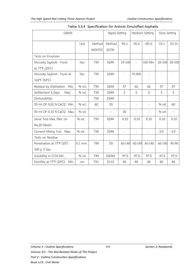
The High Speed Rail Linking Three Airports Project Outline Construction Specifications
Volume 3 : Outline Specifications 3-9 Section 3: Roadworks Volume 3/1 : The Rail-Related Works of The Project Part 2 : Outline Construction Specifications Book 1//2 : Civil Works
Table 3.3.4 Specification for Anionic Emulsified Asphalts GRADE Rapid Setting Medium Setting Slow Setting
Unit Method AASHTO
Method ASTM
RS-1 RS-2 MS-2 SS-1 SS-1h
Tests on Emulsion Viscosity Saybolt - Furol at 77°F (25°C)
Sec T59 D244 15-100 - 100 Min. 20-100 20-100
Viscosity Saybolt - Furol at 122°F (50°C)
Sec T59 D244 - 75-400 - - -
Residue by Distillation Min. % wt. T59 D244 57 62 62 57 57 Settlement 5 Days Max. % wt. T59 D244 5 5 5 5 5 Demulsibility T59 D244 35 ml OF 0.02 N CaCl2 Min. % wt. 60 50 - - - % wt. 60
50 ml OF 0.10 N CaCl2 Max. % wt. - - 30 - - % wt. -
Sieve Test Max. (Ret. on No.20 Mesh)
% wt. T59 D244 0.10 0.10 0.10 0.10 0.10
Cement Mixing Test Max. % wt. T59 D244 - - - 2.0 2.0 Tests on Residue Penetration at 77°F (25°) 100 g. 5 Sec.
0.1 mm. T49 D5 60-140 60-140 60-140 60-140 40-90
Solubility in CCl4 Min. % wt. T44 D2042 97.5 97.5 97.5 97.5 97.5 Ductility at 77°F (25°C) Min. cm T51 D113 40 40 40 40 40
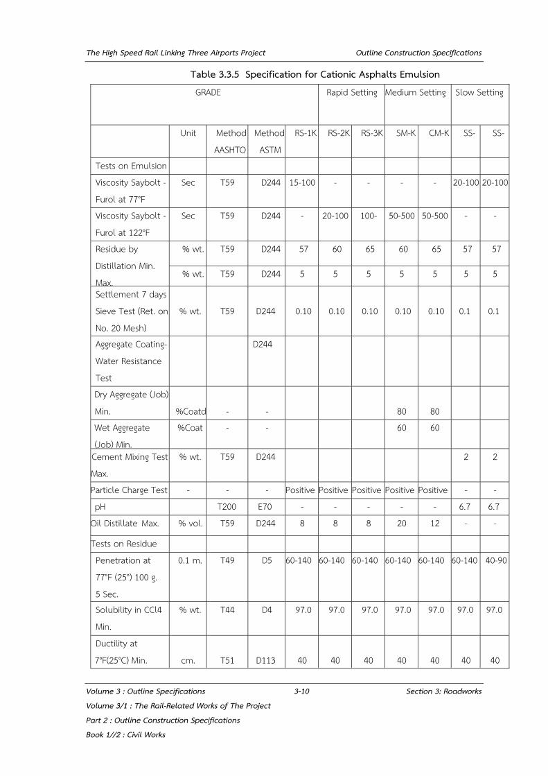
The High Speed Rail Linking Three Airports Project Outline Construction Specifications
Volume 3 : Outline Specifications 3-10 Section 3: Roadworks Volume 3/1 : The Rail-Related Works of The Project Part 2 : Outline Construction Specifications Book 1//2 : Civil Works
Table 3.3.5 Specification for Cationic Asphalts Emulsion GRADE Rapid Setting Medium Setting Slow Setting
Unit Method AASHTO
Method ASTM
RS-1K RS-2K RS-3K SM-K CM-K SS- SS-
Tests on Emulsion Viscosity Saybolt - Furol at 77°F
Sec T59 D244 15-100 - - - - 20-100 20-100
Viscosity Saybolt - Furol at 122°F
Sec T59 D244 - 20-100 100- 50-500 50-500 - -
Residue by Distillation Min. Max.
% wt. T59 D244 57 60 65 60 65 57 57
% wt. T59 D244 5 5 5 5 5 5 5
Settlement 7 days Sieve Test (Ret. on No. 20 Mesh)
% wt.
T59
D244
0.10
0.10
0.10
0.10
0.10
0.1
0.1
Aggregate Coating- Water Resistance Test
D244
Dry Aggregate (Job) Min.
%Coatd
-
-
80
80
Wet Aggregate (Job) Min.
%Coat - - 60 60
Cement Mixing Test Max.
% wt. T59 D244 2 2
Particle Charge Test - - - Positive Positive Positive Positive Positive - - pH T200 E70 - - - - - 6.7 6.7
Oil Distillate Max. % vol. T59 D244 8 8 8 20 12 - -
Tests on Residue Penetration at 77°F (25°) 100 g. 5 Sec.
0.1 m. T49 D5 60-140 60-140 60-140 60-140 60-140 60-140 40-90
Solubility in CCl4 Min.
% wt. T44 D4 97.0 97.0 97.0 97.0 97.0 97.0 97.0
Ductility at 7°F(25°C) Min.
cm.
T51
D113
40
40
40
40
40
40
40

The High Speed Rail Linking Three Airports Project Outline Construction Specifications
Volume 3 : Outline Specifications 3-11 Section 3: Roadworks Volume 3/1 : The Rail-Related Works of The Project Part 2 : Outline Construction Specifications Book 1//2 : Civil Works
3.4 ASPHALTIC PRIME COAT
3.4.1 Description
This work shall consist of the cleaning of the surface to be primed and furnishing and applying asphaltic material in accordance with these Specifications to the area as consented to by the SRT’s Representative.
3.4.2 Materials
Asphaltic material shall be a cut back grade MC 30 or MC 70 or emulsion cationic type, grade CSS-1 or CSS-1h conforming to the requirements of Section 3.3 Table 3.3.5 or TIS 371.
3.4.3 Construction Methods
3.4.3.1 Weather Limitations
Prime coat shall be applied at a time when the surface to be treated is dry or slightly damp, and when the weather is dry.
3.4.3.2 Equipment
The equipment used by the Private Party shall include a power broom and an asphaltic material distributor.
The distributor shall be so designed that asphaltic material may be applied uniformly on variable widths of surface up to 3.6 meters at controlled rates of from 0.2 to 4.0 liters per square meter with uniform pressure, and with an allowable variation from any specified rate not to exceed 0.1 liter per square meter. Distributor equipment shall include an instrument for measuring the speed of travel accurately at low speeds, the temperature of the contents of the tank, and the pressure.
3.4.3.3 Cleaning Surface
Immediately before applying the asphaltic material all loose dirt and other objectionable material shall be removed from the surface with a power broom and blower.
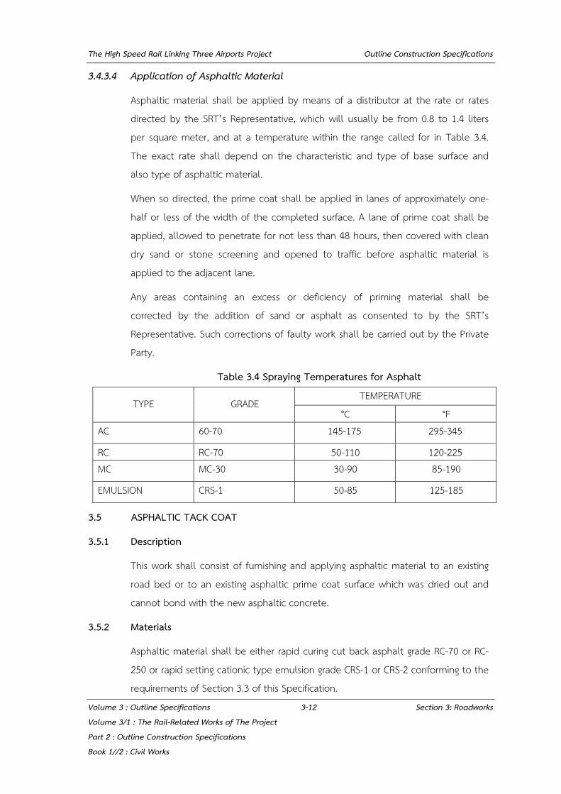
The High Speed Rail Linking Three Airports Project Outline Construction Specifications
Volume 3 : Outline Specifications 3-12 Section 3: Roadworks Volume 3/1 : The Rail-Related Works of The Project Part 2 : Outline Construction Specifications Book 1//2 : Civil Works
3.4.3.4 Application of Asphaltic Material
Asphaltic material shall be applied by means of a distributor at the rate or rates directed by the SRT’s Representative, which will usually be from 0.8 to 1.4 liters per square meter, and at a temperature within the range called for in Table 3.4. The exact rate shall depend on the characteristic and type of base surface and also type of asphaltic material.
When so directed, the prime coat shall be applied in lanes of approximately one-half or less of the width of the completed surface. A lane of prime coat shall be applied, allowed to penetrate for not less than 48 hours, then covered with clean dry sand or stone screening and opened to traffic before asphaltic material is applied to the adjacent lane.
Any areas containing an excess or deficiency of priming material shall be corrected by the addition of sand or asphalt as consented to by the SRT’s Representative. Such corrections of faulty work shall be carried out by the Private Party.
Table 3.4 Spraying Temperatures for Asphalt
TYPE GRADE TEMPERATURE
°C °F AC 60-70 145-175 295-345
RC RC-70 50-110 120-225 MC MC-30 30-90 85-190
EMULSION CRS-1 50-85 125-185
3.5 ASPHALTIC TACK COAT
3.5.1 Description
This work shall consist of furnishing and applying asphaltic material to an existing road bed or to an existing asphaltic prime coat surface which was dried out and cannot bond with the new asphaltic concrete.
3.5.2 Materials
Asphaltic material shall be either rapid curing cut back asphalt grade RC-70 or RC-250 or rapid setting cationic type emulsion grade CRS-1 or CRS-2 conforming to the requirements of Section 3.3 of this Specification.

The High Speed Rail Linking Three Airports Project Outline Construction Specifications
Volume 3 : Outline Specifications 3-13 Section 3: Roadworks Volume 3/1 : The Rail-Related Works of The Project Part 2 : Outline Construction Specifications Book 1//2 : Civil Works
3.5.3 Construction Methods
3.5.3.1 Cleaning Surface
The full width of surface to be treated shall be cleaned with a power broom or blower to remove loose dirt, sand, dust and other objectionable material.
3.5.3.2 Application of Asphaltic Material
Immediately after cleaning the surface, asphaltic material shall be applied by means of a distributor at the controlled rates of from 0.1 to 0.3 liter per square meter on bituminous surfaces of 0.3 - 0.6 liter per square meter on concrete bridge decks or as consented to by the SRT’s Representative, and at the temperature within the range called for in Table 3.4. Quantities outside the specified rates shall be adjusted by the Private Party, to the satisfaction of the SRT’s Representative.
The surfaces of structures and trees adjacent to the areas being treated shall be protected in such manner as to prevent their being spattered or marred.
Tack coat shall be applied only so far in advance of surface course placement as necessary to obtain proper condition of tackiness. The Private Party shall protect the tack coat from damage when the surface course is placed.
3.6 ASPHALTIC SURFACE TREATMENT
3.6.1 Description
This work shall consist of one or more applications of asphaltic material and cover aggregate to a primed non-asphaltic surface or to a previously constructed asphaltic surface in accordance with these Specifications and to the area as directed by the SRT’s Representative.
3.6.2 Materials
3.6.2.1 Asphaltic Materials
Asphaltic material shall be either rapid curing cut-back asphalt, grade RC-800 or RC-3000 or asphalt cement grade AC 60-70 or rapid setting cationic type emulsion grade CRS-2 conforming to the requirements of Section 3.3 of this Specification.
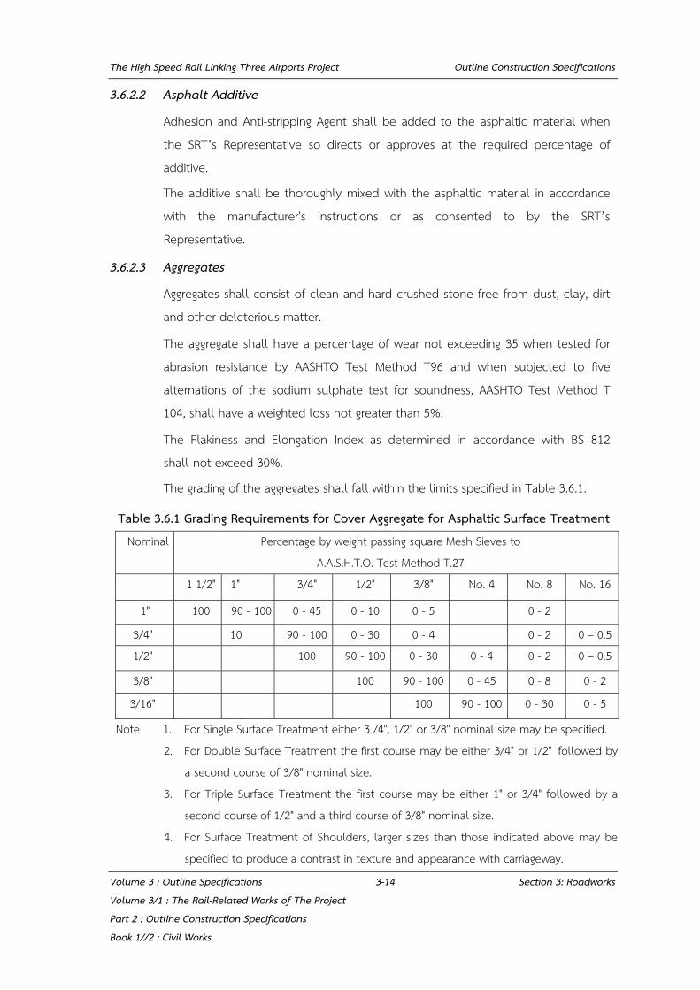
The High Speed Rail Linking Three Airports Project Outline Construction Specifications
Volume 3 : Outline Specifications 3-14 Section 3: Roadworks Volume 3/1 : The Rail-Related Works of The Project Part 2 : Outline Construction Specifications Book 1//2 : Civil Works
3.6.2.2 Asphalt Additive
Adhesion and Anti-stripping Agent shall be added to the asphaltic material when the SRT’s Representative so directs or approves at the required percentage of additive.
The additive shall be thoroughly mixed with the asphaltic material in accordance with the manufacturer's instructions or as consented to by the SRT’s Representative.
3.6.2.3 Aggregates
Aggregates shall consist of clean and hard crushed stone free from dust, clay, dirt and other deleterious matter.
The aggregate shall have a percentage of wear not exceeding 35 when tested for abrasion resistance by AASHTO Test Method T96 and when subjected to five alternations of the sodium sulphate test for soundness, AASHTO Test Method T 104, shall have a weighted loss not greater than 5%.
The Flakiness and Elongation Index as determined in accordance with BS 812 shall not exceed 30%.
The grading of the aggregates shall fall within the limits specified in Table 3.6.1.
Table 3.6.1 Grading Requirements for Cover Aggregate for Asphaltic Surface Treatment Nominal Percentage by weight passing square Mesh Sieves to
A.A.S.H.T.O. Test Method T.27
1 1/2" 1" 3/4" 1/2" 3/8" No. 4 No. 8 No. 16
1" 100 90 - 100 0 - 45 0 - 10 0 - 5 0 - 2
3/4" 10 90 - 100 0 - 30 0 - 4 0 - 2 0 – 0.5 1/2" 100 90 - 100 0 - 30 0 - 4 0 - 2 0 – 0.5
3/8" 100 90 - 100 0 - 45 0 - 8 0 - 2
3/16" 100 90 - 100 0 - 30 0 - 5
Note 1. For Single Surface Treatment either 3 /4", 1/2" or 3/8" nominal size may be specified. 2. For Double Surface Treatment the first course may be either 3/4" or 1/2" followed by
a second course of 3/8" nominal size. 3. For Triple Surface Treatment the first course may be either 1" or 3/4" followed by a
second course of 1/2" and a third course of 3/8" nominal size. 4. For Surface Treatment of Shoulders, larger sizes than those indicated above may be
specified to produce a contrast in texture and appearance with carriageway.

The High Speed Rail Linking Three Airports Project Outline Construction Specifications
Volume 3 : Outline Specifications 3-15 Section 3: Roadworks Volume 3/1 : The Rail-Related Works of The Project Part 2 : Outline Construction Specifications Book 1//2 : Civil Works
3.6.2.4 Stockpiling of Aggregates
Stockpiling of aggregates shall be permitted only where agreed by the SRT’s Representative. A separate stockpile shall be made for each nominal size of aggregate at each location.
The site of the stockpile shall be cleared of all vegetation and debris, graded and drained, and, where the SRT’s Representative deems it necessary, the area shall be surfaced with a 10 centimeter layer of approved stone or rock.
Unless otherwise consented to by the SRT’s Representative each stockpile shall be built at least 2 meters high by tipping in layers not more than one meter deep over the whole area of the stockpile. The Private Party shall supply any planking or other material required in connection with movement of vehicles over and about the stockpiles.
The bottom 5 centimeter layer of aggregate or any contaminated aggregate shall not be used in the work.
3.6.3 Construction Methods
3.6.3.1 Equipment
The Private Party shall supply all the plant and equipment necessary for carrying out the work in accordance with this Specification and shall supply details of the make, model, capacity, weight and such other details of the plant and equipment as may be required by the SRT’s Representative.
Plant and equipment shall comply with the following requirements:
a) The Asphaltic Material Distributor shall conform to the requirement of section 3.4.3.2.
b) The Power Broom shall be a rotary broom, towed or self - propelled, specifically designed for sweeping road surfaces.
c) The Drag Broom shall be capable of distributing an evenly spread aggregate without disturbing the particles freshly bedded in the binder.
d) The Aggregate Spreader shall be approved mechanical equipment capable of spreading a uniform layer of cover aggregate of the specified size in accordance with section 3.6.3.5.
The High Speed Rail Linking Three Airports Project Outline Construction Specifications
Volume 3 : Outline Specifications 3-16 Section 3: Roadworks Volume 3/1 : The Rail-Related Works of The Project Part 2 : Outline Construction Specifications Book 1//2 : Civil Works
e) Motor Trucks shall be suitable in number and performance for the application of aggregate in accordance with section 3.6.3.5.
3.6.3.2 Weather Limitation and Control of Work
No spraying shall be carried out on a wet pavement, while rain appears imminent or during high winds.
The SRT’s Representative may order work to be ceased temporarily on account of adverse weather, unsatisfactory condition of materials, equipment or pavement or any conditions which he considers may affect the work adversely.
3.6.3.3 Cleaning and Preparation of Surface
Prior to the application of binder, loose dirt and other objectionable material shall be removed from the surface by means of the power broom or blower or both. If this does not provide a uniformly clean surface, additional sweeping shall be done by hand, using stiff brushes or similar brooms. Sweeping shall extend at least 20 centimeters beyond each edge of the area to be sprayed.
Adherent patches of objectionable material shall be removed from the surface by steel scraper or other approved method and where the SRT’s Representative so directs the scraped area shall be washed down with water and hand brooms.
No application of asphaltic material shall be undertaken until the pavement has been cleaned to the satisfaction of the SRT’s Representative.
Where a prime coat has been applied to the surface, any area where the prime coat has been insufficiently applied or is defective in any way shall be re-applied as directed by the SRT’s Representative. A period of at least 48 hours or such longer period as may be necessary for the primer to become completely dry shall b e elapsed before any further asphaltic material is applied.
Before application of the asphaltic material any necessary preliminary patching of the surface of the road shall have been completed to the satisfaction of the SRT’s Representative.

The High Speed Rail Linking Three Airports Project Outline Construction Specifications
Volume 3 : Outline Specifications 3-17 Section 3: Roadworks Volume 3/1 : The Rail-Related Works of The Project Part 2 : Outline Construction Specifications Book 1//2 : Civil Works
3.6.3.4 Application of Asphaltic Material
The uniform application of asphaltic material at the rate specified or ordered shall be made by means of the distributor except that where the use of the distributor is not practicable for the application to small areas, the SRT’s Representative may consent to the application by means of hand spray equipment attached to the distributor.
Application temperature shall be within the range called for in Table 3.4 for the particular asphaltic material being used, except that for rubberized asphaltic materials a higher temperature of application may be specified or directed by the SRT’s Representative.
When an adhesion agent has been added to the asphaltic material the whole of the material in the distributor shall be circulated for at least fifteen minutes or such greater time as may be necessary to achieve a homogeneous mixture at uniform temperature.
Quantities of asphaltic materials in excess of requirements shall not be heated, nor shall such materials be held at a temperature within the range of application temperatures for periods in excess of ten hours. Any asphaltic material which has been heated for an excessive period of time or which has been overheated shall be rejected.
The area to be sprayed with asphaltic material at any time shall be limited to that which can be covered with aggregate at the specified rate within 15 minutes of the time of spraying in the case of liquid asphalts or such smaller period of time as the SRT’s Representative shall consent.
When so directed the asphaltic material shall be applied in lanes of approximately one- half or less of the width of the completed surface and when so applied there shall be a slight overlap of asphaltic material along the adjoining edges of lanes. In the case of multiple surface treatments succeeding courses shall have the asphalt joint offset by approximately 15 centimeters from the joint of the preceding application below.

The High Speed Rail Linking Three Airports Project Outline Construction Specifications
Volume 3 : Outline Specifications 3-18 Section 3: Roadworks Volume 3/1 : The Rail-Related Works of The Project Part 2 : Outline Construction Specifications Book 1//2 : Civil Works
During all applications, iron work in the road shall be covered with heavy oil or grease and the surface of adjacent structures and trees shall be protected in such manner as to prevent their surfaces from being spattered or marred.
Except for seal coats without cover aggregate, suitable paper shall be spread on the surface for a sufficient distance back from the ends of each application so that flow through the nozzles may be started and stopped on the paper and so that all nozzles will operate properly over the entire length being treated. Paper so used shall be immediately removed and disposed of in a manner satisfactory to the SRT’s Representative. The distributor shall commence moving at a sufficient distance in advance of the start of the application to ensure that the road speed for correct application is attained at the commencement of spraying and shall maintain this speed until passing the finishing point of the application.
Provision shall be made for 10 per-cent, or such other percentage as may be consented to by the SRT’s Representative, of the rated capacity of the distributor tank to be retained in the tank at the completion of each run, so as to avoid air entrainment within the delivery system and provide for any minor excess in the rate of application.
After each application, the quantity of material sprayed shall be checked against the area covered, and any necessary adjustment shall be made to ensure that the specified or ordered rate of application is maintained in subsequent runs.
Spraying shall cease immediately if any defect develops in the spraying equipment and it shall not recommence until the fault has been rectified.
3.6.3.5 Application of Cover Aggregate
Before the asphaltic material is applied, sufficient cover aggregate shall be in trucks at the site of the work to provide the full cover for the area to be sprayed. The application of the aggregate shall proceed immediately after application of asphaltic material commences and shall be completed within 15 minutes of the completion of spraying or such smaller period of time as the SRT’s Representative shall consented to.

The High Speed Rail Linking Three Airports Project Outline Construction Specifications
Volume 3 : Outline Specifications 3-19 Section 3: Roadworks Volume 3/1 : The Rail-Related Works of The Project Part 2 : Outline Construction Specifications Book 1//2 : Civil Works
The aggregate shall be spread uniformly over the asphaltic material by means of the approved aggregate spreader at the rate specified or as consented to by the SRT’s Representative. Any bare or insufficiently covered areas shall be re-run by the mechanical spreader or covered by hand as necessary to give uniform and complete coverage. Any aggregate spread in excess of the rate specified or ordered shall be scattered and evenly distributed on the road or otherwise removed and stockpiled as consented to by the SRT’s Representative.
3.6.3.6 Rolling and Brooming
Immediately after spreading to the satisfaction of the SRT’s Representative, the aggregate shall be rolled with one or more pneumatic tyred rollers or, if permitted by the SRT’s Representative, by approved steel wheeled rollers, until the aggregate is firmly embedded in the asphaltic material. Where required to ensure an even distribution of aggregate, the surface shall be broom dragged after the initial rolling except that if the drag broom has any tendency to dislodge aggregate particles bedded in the binder the SRT’s Representative may consent that drag brooming be deferred or eliminated, and that light hand brooming be substituted. Rolling shall be continued, as consented to by the SRT’s Representative, for as long as is necessary to ensure thorough incorporation of the aggregate into the binder.
Immediately after the binder has hardened to the stage at which, in the opinion of the SRT’s Representative, no more aggregate can be pressed into it by rolling, any remaining loose particles shall be removed from the pavement and shoulders.
3.6.3.7 Control of Traffic
The Private Party shall take all necessary precautions to protect the work from damage until such time as the seal coat or surface treatment has developed sufficient strength to carry normal traffic without disturbance of the aggregate.
Where it is necessary to allow early use of the new work to facilitate the movement of traffic, vehicles may be allowed to run on the work after rolling is completed provided that vehicles are controlled to such slow speeds that no displacement of aggregate occurs.

The High Speed Rail Linking Three Airports Project Outline Construction Specifications
Volume 3 : Outline Specifications 3-20 Section 3: Roadworks Volume 3/1 : The Rail-Related Works of The Project Part 2 : Outline Construction Specifications Book 1//2 : Civil Works
The Private Party shall take all necessary steps to avoid or minimise delays and inconvenience to road users during the course of the work. Where adequate detours or side-tracks are available, traffic shall be temporarily diverted while the work is in progress. Adequate signs, signals, barriers and lamps for the warning and guidance of traffic shall be provided at all times during the course of the work.
No traffic shall be permitted to pass the working area during the application of asphaltic material nor shall traffic be permitted to encroach upon the edge of asphaltic material until such time as it is covered with aggregate.
The Private Party shall take all reasonable precautions to protect traffic against damage or disfigurement by construction equipment, tools and materials, splashes and smirches of asphalt or other construction materials and shall be responsible for any claims arising from such damage or disfigurement.
3.7 ASPHALTIC CONCRETE SURFACING
3.7.1 Description
3.7.1.1 General
This work shall consist of a surfacing of dense grade asphaltic concrete, constructed on a prepared base or structure in accordance with these Specifications and the lines, levels, grades, dimensions and cross section as consented to by the SRT’s Representative.
The surfacing shall consist of one or two layers of the thickness. The top layer shall be denoted as the wearing course and the lower layer as the binder course. For a single layer surfacing, only the wearing course shall be applied.
3.7.1.2 Basic Design
Marshall Method of Mix Design as described in the Asphalt Institute Handbook MS-2 shall be used for design of mixture of aggregate and asphaltic material for surfacing of asphaltic concrete.
3.7.1.3 Composition of the Mixture
The mixture shall consist of mineral aggregate and filler if needed, coated with asphalt cement. The total mineral aggregate shall have a job mix grading within the limits set by Table 3.7 even allowing for tolerances. In exceptional cases the
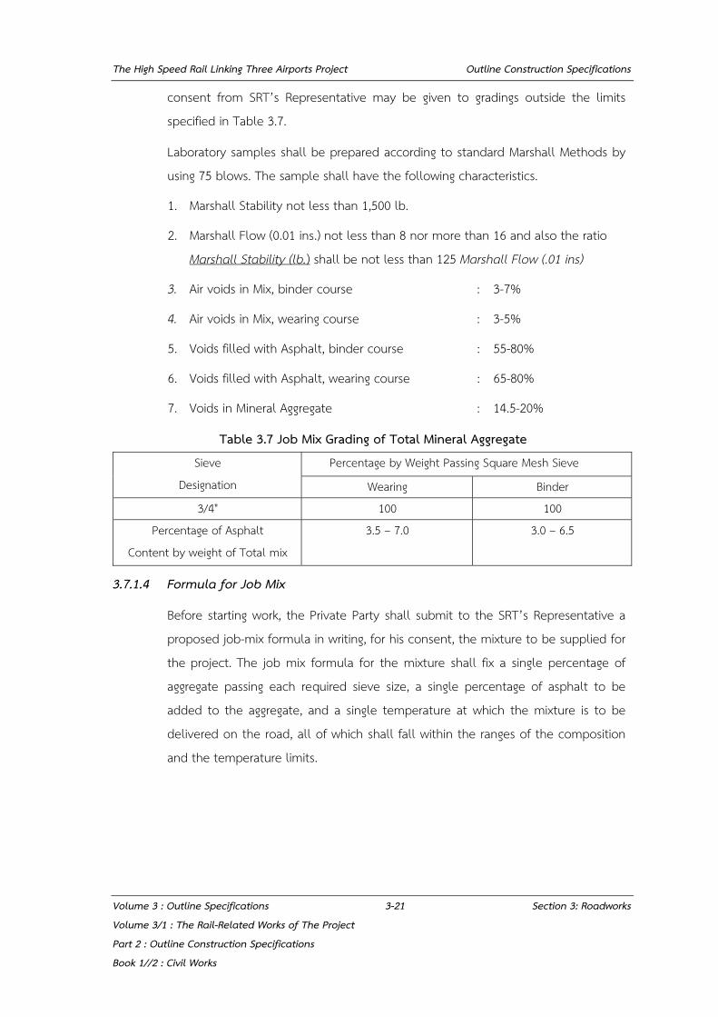
The High Speed Rail Linking Three Airports Project Outline Construction Specifications
Volume 3 : Outline Specifications 3-21 Section 3: Roadworks Volume 3/1 : The Rail-Related Works of The Project Part 2 : Outline Construction Specifications Book 1//2 : Civil Works
consent from SRT’s Representative may be given to gradings outside the limits specified in Table 3.7.
Laboratory samples shall be prepared according to standard Marshall Methods by using 75 blows. The sample shall have the following characteristics.
1. Marshall Stability not less than 1,500 lb.
2. Marshall Flow (0.01 ins.) not less than 8 nor more than 16 and also the ratio Marshall Stability (lb.) shall be not less than 125 Marshall Flow (.01 ins)
3. Air voids in Mix, binder course : 3-7%
4. Air voids in Mix, wearing course : 3-5%
5. Voids filled with Asphalt, binder course : 55-80%
6. Voids filled with Asphalt, wearing course : 65-80%
7. Voids in Mineral Aggregate : 14.5-20%
Table 3.7 Job Mix Grading of Total Mineral Aggregate Sieve
Designation Percentage by Weight Passing Square Mesh Sieve
Wearing Binder 3/4" 100 100
Percentage of Asphalt Content by weight of Total mix
3.5 – 7.0 3.0 – 6.5
3.7.1.4 Formula for Job Mix
Before starting work, the Private Party shall submit to the SRT’s Representative a proposed job-mix formula in writing, for his consent, the mixture to be supplied for the project. The job mix formula for the mixture shall fix a single percentage of aggregate passing each required sieve size, a single percentage of asphalt to be added to the aggregate, and a single temperature at which the mixture is to be delivered on the road, all of which shall fall within the ranges of the composition and the temperature limits.
The High Speed Rail Linking Three Airports Project Outline Construction Specifications
Volume 3 : Outline Specifications 3-22 Section 3: Roadworks Volume 3/1 : The Rail-Related Works of The Project Part 2 : Outline Construction Specifications Book 1//2 : Civil Works
3.7.1.5 Applications of Job-Mix Formula and Allowable Tolerances
All mixture furnished shall conform to the job-mix formula consented to by the SRT’s Representative, within the ranges of tolerance given below.
Passing No.4 Sieve ±5%
Passing No.8 Sieve ±4%
Passing No.30 Sieve ±3%
Passing No.200 Sieve ±1%
Asphalt ± 0.30%
Temperature of mixture when emptied from mixer ± 11°C
Temperature of mixture at delivery on road ± 11°C
Each day as many samples of the materials and mixture shall be taken and tested as the SRT’s Representative considers necessary for checking the required uniformity of the mixture. When unsatisfactory results or changed conditions make it necessary, the SRT’s Representative may consented to a new job mix.
Should a change in a material be encountered or should a change in a source of material be made, a new job-mix formula shall be submitted and approved before the mixture containing the new material is delivered. Job materials will be rejected if they are found to have voids or other characteristics requiring, for a balanced mix, an asphalt content greater or less than the specified range.
3.7.2 Materials
3.7.2.1 Bituminous Materials
Bituminous materials shall be asphalt cement of the type and grade consented to by the SRT’s Representative.
3.7.2.2 Coarse Mineral Aggregate
The portion of the aggregate retained on the No. 4 sieve shall be defined as coarse aggregate and shall be crushed stone.
Coarse aggregate shall have a percentage of wear less than 35 as determined by AASHTO Test Method T96 and when subjected to five alternations of the sodium sulphate soundness test, using AASHTO Test Method T 104, shall have a weight loss less than 9%.
The High Speed Rail Linking Three Airports Project Outline Construction Specifications
Volume 3 : Outline Specifications 3-23 Section 3: Roadworks Volume 3/1 : The Rail-Related Works of The Project Part 2 : Outline Construction Specifications Book 1//2 : Civil Works
Coarse aggregate shall have the Flakiness and Elongation Index less than 30 percent as determined by BS 812 and when subjected to coating and Stripping Test in accordance to AASHTO Test Method T182 shall have a coated area of not less than 95%.
3.7.2.3 Fine Mineral Aggregate
The portion of aggregate passing the No.4 sieve shall be defined as fine aggregate, and shall consist of natural sand, stone screenings, or combination, free from vegetable matter, soft particles, clay, and other objectionable matter.
The fine aggregate shall have the value of Sand Equivalent more than 50% as determined by AASHTO Test Method T 176.
3.7.2.4 Mineral Filler
Mineral filler where required shall be Portland cement or hydrated lime at least 1.5% by weight of total aggregate.
3.7.2.5 Asphalt Additive
The provision of Section 3.6.2.2 shall apply.
3.7.3 Construction Methods
3.7.3.1 Weather Limitation
Asphaltic mixtures shall be placed only when the surface is dry, when the weather is not rainy and when the prepared roadbed is in a satisfactory condition; provided, however that the SRT’s Representative may consent to, in case of sudden rain, the placing of mixture then in transit from the plant, if laid at proper temperature and if the roadbed is free from pools of water. Such consent shall in no way relax the requirements for quality and smoothness of surface.
3.7.3.2 Progress of Work
No work shall be performed when there is insufficient hauling, spreading or finishing equipment, or labour to ensure progress at a rate not less than 75% of the capacity of the mixing plant.
The High Speed Rail Linking Three Airports Project Outline Construction Specifications
Volume 3 : Outline Specifications 3-24 Section 3: Roadworks Volume 3/1 : The Rail-Related Works of The Project Part 2 : Outline Construction Specifications Book 1//2 : Civil Works
3.7.3.3 Plant and Equipment
All plant used by the Private Party for the preparation of asphalt mixtures shall conform to all of the requirements below:
a) The mixing plant shall be a batching plant and shall have a capacity at least 60 tons per hour output sufficient to supply the finisher on the road continuously when spreading the asphaltic mix at normal speed and required thickness.
b) Scale for any weight box shall be designed to be accurate to within 1% of the maximum load required and shall be fully automatically controlled.
Scale shall have been consented to by the SRT’s Representative and shall be checked as often as the SRT’s Representative may deem necessary to ensure their continued accuracy.
The Private Party shall provide and have at hand not less than ten 25 kilogram weights for frequent testing of all scales.
c) Weigh box or hopper shall include a means for accurately weighing each bin size of aggregate in a weight box or hopper, suspended on scales, ample in size to hold a full batch without running over.
d) The asphaltic cement shall be stored in storage tanks designed to keep the temperature of the asphaltic material at maximum temperature of 100ºC. The properties of the asphaltic material kept in that storage tank shall be in good condition before mixing.
The plant shall be provided with the circulating system to ensure continuous circulation between the storage tank and the mixer.
e) The plant shall have at least 4 cold bins for feeding the aggregates and a separate silo for filler. Bin shall have a calibration gate and a mechanical means to insure uniform feeding of the aggregates into the drier as consented to by the SRT’s Representative.
f) The rotary drier shall be capable of drying and heating the aggregates to the specified temperature.

The High Speed Rail Linking Three Airports Project Outline Construction Specifications
Volume 3 : Outline Specifications 3-25 Section 3: Roadworks Volume 3/1 : The Rail-Related Works of The Project Part 2 : Outline Construction Specifications Book 1//2 : Civil Works
g) The plant shall be provided with plant screens capable of screening all aggregate to the specified sizes.
h) The plant shall include at least 4 hot bins for storing the aggregates fed from the drier after passing through the screen. Each bin shall be provided with an overflow pipe to prevent any backing up of material into other bins.
i) The plant shall be provided with asphaltic control unit by weighing to obtain the proper amount of asphaltic material in the mix within the tolerance specified for the job-mix.
j) The batch mixer shall be an approved twin pugmill type and capable of producing a continuous uniform mixture within the job-mix tolerances. The mixer capacity shall not be less than 1,000 kilogram batch.
k) An armored thermometer reading from 50ºC to 200ºC shall be fixed in the asphaltic feed line at a suitable location near the discharge valve at the mixer unit.
The plant shall be further equipped with an electric pyrometer, or other approved thermometric instrument so placed at the discharge chute of the drier as to register automatically or indicate the temperature of the heated aggregate.
l) The plant shall be equipped with a dust collector consisting of dry type for primary collector and wet type for secondary collector.
m) The plant shall be equipped with accurate positive means to govern the time of mixing and to maintain it constant unless changed, subjected to the consent of the SRT’s Representative. The time of mixing shall be divided into two steps, dry mixing and wet mixing. For dry mixing, the aggregate from hot bins shall be mixed for a period of 5-15 seconds. For wet mixing, the mixing time shall begin with the start of the asphalt spray after dry mixing. The wet mixing takes 30-45 seconds. The mixing time shall be extended if in the consideration of the SRT’s Representative the material obtained is not homogeneous.
n) Plant shall conform to AASHTO M156 - Requirements for Mixing Plants for Hot- Mixed Hot-Laid Bituminous Paving Mixtures.
The High Speed Rail Linking Three Airports Project Outline Construction Specifications
Volume 3 : Outline Specifications 3-26 Section 3: Roadworks Volume 3/1 : The Rail-Related Works of The Project Part 2 : Outline Construction Specifications Book 1//2 : Civil Works
3.7.3.4 Equipment for Hauling and Placing
a) Trucks for hauling asphaltic mixtures shall have tight, clean, and smooth metal beds that have been sprayed with soapy water, thinned fuel oil, or lime solution to prevent the mixing from adhering to the beds. The amount of sprayed fluid shall however to keep to the practical minimum. Each load shall be covered with a canvas or other suitable material of such size as to protect the mixture from the weather. Any truck causing excessive segregation of material by its spring suspension or other contributing factors, or that shows oil leaks in detrimental amounts, or that causes undue delays, shall be removed from the work until such conditions are corrected.
b) The equipment for spreading and finishing shall be approved mechanical, self powered pavers, capable of spreading and finishing the mixture true to the lines, grades, levels, dimensions and cross sections.
The pavers shall be equipped with hoppers and distributing screws of the reversing type to place the mixture evenly.
The pavers shall maintain trueness of grade and confine the edges of the pavement to true lines without the use of stationary side forms. The equipment shall include blending or joint levelling devices for smoothing and adjusting longitudinal joints between lanes.
The assembly shall be adjustable to give the cross-section shape prescribed and shall be so designed and operated as to place the thickness or weight per square meter of material required.
Pavers shall be equipped with activated screeds and devices for heating the screeds to the temperature required for the laying of the mixture without pulling or marring.
The term "screed" includes any cutting, crowding, or other practical action that is effective in producing a finished surface of the evenness and texture specified, without tearing, shoving, or gouging.
If, during construction, it is found that the spreading and finishing equipment in operation leaves in the pavement surface tracks or indented areas or other objectionable irregularities, the use of such equipment shall be discontinued and

The High Speed Rail Linking Three Airports Project Outline Construction Specifications
Volume 3 : Outline Specifications 3-27 Section 3: Roadworks Volume 3/1 : The Rail-Related Works of The Project Part 2 : Outline Construction Specifications Book 1//2 : Civil Works
other satisfactory spreading and finishing equipment shall be provided by the Private Party forthwith.
3.7.3.5 Preparation of Existing Surface
Where local irregularities in the existing surface would otherwise result in a course more than 7.5 centimeters thick after compaction, the surface shall be brought to uniform contour by patching with an asphaltic mixture, and thoroughly compacted by tamping or rolling until it conforms with the surrounding surface. The mixture used shall be the same as that specified for the next course.
Where the existing roadbed is broken or shows instability, the unstable material shall be removed and disposed of and be replaced with the same mixture as specified for the next course, compacted to the standard and elevation of the adjacent surface.
The surface upon which the mixture is to be placed shall be swept thoroughly and cleaned of all loose dirt and other objectionable material immediately before spreading the mixture.
Before spreading the mixture upon a portland cement concrete surface all longitudinal and transverse joints shall be cleaned out and filled with an approved sand asphalt mix. Cracks shall be similarly treated as directed by the SRT’s Representative.
3.7.3.6 Preparation of Asphaltic Material
Asphalt cement shall be heated to a temperature between 151 ºC and 167 ºC. The Private Party shall submit the exact temperature for the consent of the SRT’s Representative.
3.7.3.7 Preparation of Mineral Aggregate
The mineral aggregates shall be dried and heated to a temperature between 155ºC and 171ºC. The Private Party shall submit the exact temperature for the approval by the SRT’s Representative. Surfaces of aggregates shall be clean and free of carbon and unburnt fuel oil.
The aggregates, immediately after heating, shall be screened into three or more fractions and conveyed into separate bins ready for combining and mixing with asphaltic material.
The High Speed Rail Linking Three Airports Project Outline Construction Specifications
Volume 3 : Outline Specifications 3-28 Section 3: Roadworks Volume 3/1 : The Rail-Related Works of The Project Part 2 : Outline Construction Specifications Book 1//2 : Civil Works
3.7.3.8 Preparation of Mixing
The dried mineral aggregates prepared as prescribed above, shall be combined in the plant in the amount of each fraction of aggregate required to meet the job-mix formula for the particular mixture. The asphaltic material shall be measured or gauged and introduced into the mixer in the amount determined by the SRT’s Representative.
The proper amount of asphaltic material shall be distributed over the mineral aggregate and the whole thoroughly mixed for a period of at least 30 seconds, or longer if necessary to produce a homogeneous mixture in which all particles of the mineral aggregate are coated uniformly. The total mixing time shall be set by the SRT’s Representative and regulated by a suitable locking means.
The mixture shall when emptied from the mixer be at a temperature between 145ºC and 170ºC even for tolerances. The Private Party shall submit the exact temperatures for the consent of the SRT’s Representative.
3.7.3.9 Transportation and Delivery of Mixture
The mixture shall be transported from the mixing plant to the point of use in vehicles conforming to the requirement of 3.7.3.4 (a).
Each vehicle shall be weighed after each loading at the mixer and a record shall be kept of the gross weight, tare and net weight of each load.
3.7.3.10 Spreading and Finishing
Upon arrival at the point of use, the mixture shall be spread and struck off to the grade, elevation, and cross-section shape intended, either over the entire width or over such partial width as may be practicable. Asphaltic mixture pavers conforming to the requirements of Item 3.7.3.4 (b) shall be used for this purpose. The mixture shall be laid upon an approved surface and only when weather conditions are considered suitable by the SRT’s Representative.
Unless the asphaltic concrete is laid directly onto a clean prime coat, a tack coat shall be applied to the underlying surface prior to spreading the asphaltic concrete surfacing.
The High Speed Rail Linking Three Airports Project Outline Construction Specifications
Volume 3 : Outline Specifications 3-29 Section 3: Roadworks Volume 3/1 : The Rail-Related Works of The Project Part 2 : Outline Construction Specifications Book 1//2 : Civil Works
On areas where the use of spreading equipment is considered impractical the mixture shall be dumped on steel boards then spread raked and luted by hand to provide the correct weight or uniform thickness of material without segregation.
Spreading, finishing and compacting of asphaltic concrete shall be carried out during daylight hours unless satisfactory illumination is provided by the Private Party.
3.7.3.11 Compaction of Mixture
a) Immediately after the mixture has been spread and struck off, the surface shall be checked and any inequalities adjusted. The mixture shall then be thoroughly and uniformly compacted by rolling. Each course shall be rolled as soon after being placed as the material will support the roller without undue displacement or cracking.
b) Generally, with each paver, two steel wheeled tandem rollers and 3 pneumatic tired rollers will be required.
All rollers shall be self propelled, capable of being reversed without backlash and equipped with power steering, water tanks, sprinkler systems and coco-mats to ensure even wetting of rolls or tyres. Each roller shall be in good condition and worked by a competent and experienced operator.
Steel wheeled tandem rollers shall weigh not less than 8 metric tons with water sprinkler system and scraper and each tandem roller used for final compaction shall have at least one roll capable of applying a minimum rolling pressure of 37.9 kilograms per centimeter of roll width.
Pneumatic tired rollers shall weigh not less than 10 metric tons and having not less than nine wheels smooth tread compactor tires of equal size and construction capable of operating at inflation pressures up to 120 pounds per square inch. Means shall be provided for checking and adjusting the tire pressures on the job at all times. In general the compaction of any course with a pneumatic tired roller shall be accomplished with contact pressures as high as the material will support.
The High Speed Rail Linking Three Airports Project Outline Construction Specifications
Volume 3 : Outline Specifications 3-30 Section 3: Roadworks Volume 3/1 : The Rail-Related Works of The Project Part 2 : Outline Construction Specifications Book 1//2 : Civil Works
c) Rolling of the mix shall consist of six separate operations as follows:
• transverse joint
• longitudinal joint
• edges
• initial or breakdown rolling
• second or intermediate rolling
• finish rolling
The first rolling of all joints and edges, the initial or breakdown rolling and the final or finish rolling shall all be done with the steel wheeled tandem rollers. The second or intermediate rolling shall be done with the pneumatic tired roller.
Rolling shall start longitudinally at the sides and proceed toward the center of the pavement except that on superelevated curves rolling shall begin at the low side and progress toward the high side. Successive trips of the roller shall overlap by at least one half of the width of the roller and alternate trips shall not terminate at the same point. For initial rolling the drive roll should be nearest the paver.
The speed of the rollers shall not exceed 5 kilometers per hour for steel wheeled rollers and 7 kilometers per hour for pneumatic tired rollers and shall be at all times slow enough to avoid displacement of the hot mixture. Any displacements occurring as a result of reversing the direction of the roller or from any other cause shall at once be corrected with rakes and fresh mixture where required. Care shall be exercised in rolling not to displace the line and grade of the edges.
Rolling shall progress continuously as may be necessary to obtain uniform compaction while the mixture is in a workable condition and until all roller marks are eliminated.
To prevent adhesion of the mixture to the roller, the wheels shall be kept properly moistened, but excess water will not be permitted.
Heavy equipment or rollers shall not be permitted to stand on the finished surface until it has thoroughly cooled or set.

The High Speed Rail Linking Three Airports Project Outline Construction Specifications
Volume 3 : Outline Specifications 3-31 Section 3: Roadworks Volume 3/1 : The Rail-Related Works of The Project Part 2 : Outline Construction Specifications Book 1//2 : Civil Works
Any petroleum products dropped or spilled from the vehicles or equipment employed by the Private Party upon any portion of the pavement under construction is cause for the removal and replacement of the contaminated pavement by the Private Party.
Along curbs, manholes, and similar structures and at all places not accessible by the roller, thorough compaction shall be secured by means of hot hand tampers or with mechanical tampers giving equivalent compaction. Each hand tamper shall weigh not less than 10 kilograms and shall have a tamping face area of not more than 250 square centimeters.
The surface of the mixture after compaction shall be smooth and true to the established crown and grade within the tolerance specified. Any mixture that becomes loose and broken, mixed with dirt, or which is defective in any way, shall be removed and replaced with fresh hot mixture, which shall be compacted immediately to conform with the surrounding area.
Any area of 1,000 square centimeters or more showing an excess or deficiency of asphaltic material shall be removed and replaced. All high spots, high joints, depressions, and honeycombs shall be adjusted.
No delays in rolling the paved surface shall be tolerated, the breakdown roller must be right up to the paver at all times and the intermediate pneumatic roller right up to the breakdown roller.
The compaction of the asphaltic concrete shall be controlled by temperature as
follows.
Roller Temperature
Breakdown 120°C - 135°C
Pneumatic 95°C - 115°C
Finishing > 66°C
The asphaltic concrete shall be sufficiently hot so that it moves under the breakdown and pneumatic rollers. If the asphalt plant breaks down then the breakdown roller should complete its work and depart from the new asphaltic concrete surface so that the pneumatic roller can finish its compaction at the
The High Speed Rail Linking Three Airports Project Outline Construction Specifications
Volume 3 : Outline Specifications 3-32 Section 3: Roadworks Volume 3/1 : The Rail-Related Works of The Project Part 2 : Outline Construction Specifications Book 1//2 : Civil Works
required temperature. The Private Party should have at least two thermometers on hand at the paving for taking the temperature of the asphaltic concrete layer.
3.7.3.12 Joints
Both longitudinal and lateral joints in successive courses shall be staggered so as not to be one above the other. Longitudinal joints shall be arranged so that the longitudinal joint in the top course shall be at the location of the line dividing the traffic lanes. Lateral joints shall be staggered a minimum of 50 centimeters and shall be straight.
Longitudinal and transverse joints shall be made in a careful manner so that well bonded and sealed joints are provided for the full depth of the course. No mixture shall be placed against previously rolled material unless the edge is vertical or has been cut back to a vertical face. A brush coat of hot asphalt shall be applied just before additional mixture is placed against the previously rolled material.
Spreading shall be as nearly continuous as possible and rollers shall pass over the unprotected end of freshly laid mixture only when consented to by the SRT’s Representative.
Before placing mixtures against them all contact surfaces of curbs, gutters, manholes etc. shall be given a thin uniform coating of hot asphalt and the joints between these structures and the surface mixture shall be effectively sealed by the subsequent spreading, finishing and compaction operations.
3.7.3.13 Control and Testing
a) The Private Party shall provide adequate laboratory accommodation and all the equipment required for sampling and each of the following tests.
Sand Equivalent of aggregates Bulk specific gravity of mixed aggregates Compacted density of mix (Marshall Density) Marshall Stability and Flow Density of compacted surface course Asphalt extraction

The High Speed Rail Linking Three Airports Project Outline Construction Specifications
Volume 3 : Outline Specifications 3-33 Section 3: Roadworks Volume 3/1 : The Rail-Related Works of The Project Part 2 : Outline Construction Specifications Book 1//2 : Civil Works
b) The Private Party shall be responsible for this sampling and testing and shall provide an adequate number of skilled assistants to do this work. The SRT’s Representative may however from time to time decide to take the samples and/or do the tests himself.
c) The Private Party shall keep records of all his tests and these records shall be sent to the SRT’s Representative continuously.
3.7.3.14 Surface Test of the Pavement
The surface shall be tested by a crown template and 3 meter straight edge, furnished by the Private Party, applied respectively at right angles and parallel, to the centerline of the road. The Private Party shall designate some employee to use the template and straight edge under the direction of the SRT’s Representative in checking all surfaces. The crown template shall conform to the typical cross section.
The variation of the surface from the testing edge of the crown template and the straight edge between any two contacts with the surface shall not exceed 3.5 millimeters.
Tests for conformity with the specified crown and grade shall be made immediately after initial compaction, and variations shall be corrected by removing or adding materials as may be necessary. Rolling shall then be continued as specified. After final rolling, the smoothness of the course shall be checked again and any irregularity of the surface exceeding corrected, including removal and replacement.
3.7.3.15 Protection of the Pavement
Sections of the newly finished work shall be protected from traffic of any kind until the mixture has cooled to approximately ambient air temperature. Traffic shall not normally be permitted on the newly laid surface less than 16 hours after completion of the pavement, except with the consent of the SRT’s Representative.

The High Speed Rail Linking Three Airports Project Outline Construction Specifications
Volume 3 : Outline Specifications 3-34 Section 3: Roadworks Volume 3/1 : The Rail-Related Works of The Project Part 2 : Outline Construction Specifications Book 1//2 : Civil Works
3.8 REINFORCED CONCRETE PAVEMENT
3.8.1 Description
3.8.1.1 General
This work shall consist of constructing reinforced concrete pavement as described in the Specification, on a prepared and accepted subbase in accordance with this Specification and in conformity with the lines, levels, grades and dimension in accordance with the design. Reinforced concrete shall consist of a mixture of Portland cement, fine aggregate, coarse aggregate, water and reinforcement, with or without admixtures.
3.8.1.2 Compressive Strength of Concrete
As times during the progress of concreting, test cylinders shall be made. Six-inch cylinders tested in accordance with AASHTO Test Method T22 shall show a characteristic strength of not less than 250 kilograms per square centimeter at 28 days.
Sets of test cylinders shall be made at intervals in accordance with AASHTO Test Method T 23 each time concrete is poured, each pair being from a different batch of concrete. At the start of work, and until such time as the SRT’s Representative may order a reduction in the number of test cylinders required, not less than four pairs shall be made each day, half of them for testing at 28 days for determination of the minimum permissible crushing strength and the other half at an early age, usually 7 days, for the information of the SRT’s Representative. When the first thirty results are available and for as long as the SRT’s Representative is satisfied with the quality control of the mix, he may reduce the number of the test cylinders required. Depending on the output of concrete and other variables, the number of sets of test cylinders made will be in the range between a lower limit of one and six at the 400 cubic meters level of production.
After it has been established that the specified crushing strength is being regularly obtained or exceeded, and provided that the source and quality of the materials remain constant, the SRT’s Representative may waive the making of test cylinders for testing at an early age. One test cylinder from each of two batches of
The High Speed Rail Linking Three Airports Project Outline Construction Specifications
Volume 3 : Outline Specifications 3-35 Section 3: Roadworks Volume 3/1 : The Rail-Related Works of The Project Part 2 : Outline Construction Specifications Book 1//2 : Civil Works
concrete shall be made each day for testing at 28 days. Records shall be kept at the location at which concrete used in the test cylinders was abstracted.
If a minimum characteristic crushing strength of 250 kilograms per square centimeter is not so attained, the Private Party shall drill cores from locations selected by the SRT’s Representative. Where this is done the strength of cores when tested in accordance with AASHTO Test Method T22 will be accepted as taking precedence over the test cylinder strengths in determining the strength of the concrete and core strengths of not less than 250 kilograms per square centimeter at 28 days will be accepted for a core of minimum diameter not less than 3 inches having a height/diameter ratio of 2:1.
3.8.1.3 Grading of Aggregates
The grading of the aggregates shall be within the limits as specified in Clause 3.8.2, Materials. Once the appropriate grading, including the grading zone of the fine aggregate, has been determined and approved, it shall not be varied without the consent of the SRT’s Representative.
3.8.1.4 Constituents of the Mix
All materials in the mix shall be proportioned wholly by weight. The cement and the coarse and fine aggregates shall be as specified in Section 3.8.2, Materials. The aggregate cement ratio shall not exceed 7:1 by weight. The maximum size of aggregate shall be 37.5 mm unless otherwise consented to by the SRT’s Representative.
3.8.1.5 Water Cement Ratio
The ratio of free water to cement for saturated surface-dry aggregate shall not exceed 0.55 by weight for all concrete. Minimum cement content shall be 350 kilograms per cubic meter of concrete.
3.8.1.6 Limit of Workability
The concrete shall be of suitable workability for full compaction to be obtained with the equipment used and without undue flow. The slump as measured by AASHTO Test Method T119 shall be not greater than 6.0 centimeters.
The High Speed Rail Linking Three Airports Project Outline Construction Specifications
Volume 3 : Outline Specifications 3-36 Section 3: Roadworks Volume 3/1 : The Rail-Related Works of The Project Part 2 : Outline Construction Specifications Book 1//2 : Civil Works
3.8.1.7 Trial Mixes
Trial mixes shall commence at least one month before pavement concreting is anticipated.
On the bases of the results from the mix design, the SRT’s Representative will designate weight in kilograms of fine and coarse aggregate (in saturated surface dry condition) per kilogram of cement, the cement content in kilogram per cubic meter, and the water-cement ratio which will be required for a specified class of concrete. These proportions shall not be changed during the progress of the Works, except with the consent in writing of the SRT’s Representative. In addition, the SRT’s Representative will designate the batch weights of aggregates, as well, after he has made moisture determinations and corrected the saturated surface-dry weights for free moisture.
Consent to a mix by the SRT’s Representative does not relieve the Private Party of the responsibility to ensure that the concrete is in accordance with the requirements of these Specifications. The SRT’s Representative may at any time require the Private Party to redesign the mix, if the SRT’s Representative feels that the concrete does not satisfy the requirements of this Specification.
3.8.2 Materials
3.8.2.1 Portland cement
Cement shall conform to the requirement of AASHTO Standard Specification M 85 Type 1 or Type 3 or TIS Type 1 or Type 3.
The product of only one mill or any one brand and type of Portland cement shall be used on the concrete pavement unless otherwise consented to by the SRT’s Representative.
The Private Party shall provide suitable means for storing and protecting the cement against dampness. Cement which, for any reason, has become partially set or which contains lumps of caked cement shall be rejected. Cement salvaged from discarded or used sacks shall not be used.

The High Speed Rail Linking Three Airports Project Outline Construction Specifications
Volume 3 : Outline Specifications 3-37 Section 3: Roadworks Volume 3/1 : The Rail-Related Works of The Project Part 2 : Outline Construction Specifications Book 1//2 : Civil Works
3.8.2.2 Admixtures
Admixtures shall only be used when consented to by the SRT’s Representative.
The Private Party shall submit samples of any admixture he proposes to use to the SRT’s Representative at least 28 days prior to the date of commencement of construction of the concrete pavement on which he intends to use such admixture.
Admixtures if permitted shall conform to the requirement of AASHTO Standard Specifications M 154 and M 194.
3.8.2.3 Aggregates
Aggregates shall conform to AASHTO Standard Specifications M 6 for fine aggregates and M 80 for coarse aggregates used for Portland Cement Concrete.
The percentage of wear in accordance with AASHTO T 96 shall be less than 40. Aggregates shall be so stored as to prevent the inclusion of foreign material. Aggregates shall not be placed upon the finished roadbed. Aggregates of different sizes and kinds shall be placed in different stockpiles.
Washed aggregates and aggregates produced or manipulated by methods which involve the use of water shall be allowed to drain at least 12 hours before use.
3.8.2.4 Water
The water used in mixing or curing concrete shall be tested by methods described in AASHTO Test Method T 26. All water shall be clean and free from salt, oil or acid, vegetable or other substances injurious to the finished product.
The type of water to be used shall be subject to written consent by the SRT’s Representative.
Water to be used for curing of the concrete pavement shall be available and on the site before any concrete shall be poured.
The High Speed Rail Linking Three Airports Project Outline Construction Specifications
Volume 3 : Outline Specifications 3-38 Section 3: Roadworks Volume 3/1 : The Rail-Related Works of The Project Part 2 : Outline Construction Specifications Book 1//2 : Civil Works
3.8.2.5 Reinforcement steel
a) General
Pavements shall be reinforced as per the design consented to by the SRT’s Representative including dowels, tie bars and all other necessary details. Steel reinforcement shall conform to Section 5.1.4.1.
Reinforcement shall extend to within 5 centimeters of each side of the slab. The sheets shall be furnished in such lengths with at least the minimum lap between sheets, that the reinforcement extend to within 5 centimeters of transverse expansion or contraction joints.
All reinforcement steel shall be on site adjacent to the concreting side before any pouring of the concrete is allowed.
b) Steel Reinforcement
Steel reinforcement shall conform to the requirements of Section 5.1.4.1.
c) Bar-Mat Reinforcement
Bar-mat reinforcement shall conform to the requirement of AASHTO Standard Specification M 54. The bars used shall conform to the requirements of AASHTO Standard Specifications M 31 or M 42. Members shall be of the size and spacings specified by the Designer.
d) Dowel and Tie Bars
Dowel and tie bars shall conform to the requirements of Section 5.1.4.1. Dowel bars shall be plain round bars. They shall be free from burring or other deformation restricting slippage in the concrete. Before delivery to the Works, one-half of the length of each dowel bar shall be painted with one coat of asphaltic material.
Tie bars shall be deformed bars. Rail steel shall not be used for the bars which are to be bent and re-straightened during construction.

The High Speed Rail Linking Three Airports Project Outline Construction Specifications
Volume 3 : Outline Specifications 3-39 Section 3: Roadworks Volume 3/1 : The Rail-Related Works of The Project Part 2 : Outline Construction Specifications Book 1//2 : Civil Works
3.8.2.6 Sleeves
The sleeves for dowel bars of expansion joints shall be of plastic material. This shall be designed to cover the dowels with a closed end, and with a suitable stop to hold the end of the sleeve a distance equal to the thickness of joint filler or at least 3.0 centimeters from the end of the dowel bar. Sleeves shall be of such design that they do not deflect or collapse during construction, and the arrangement of sleeves shall be in accordance with Clause 3.8.4.9.
3.8.2.7 Subbase base materials
Granular material conforming to Section 3.1 shall be used immediately beneath all concrete pavements unless otherwise directed by the SRT’s Representative.
3.8.2.8 Waterproof membrane
Waterproof underlay shall consists of impermeable polythene plastic sheeting 0.15mm thick. Where an overlap of underlay material is necessary this shall be at least 30 centimeters. Water shall not be allowed to pond on the membrane which shall be completely waterproof when the concrete is laid.
3.8.2.9 Jointing materials
a) Joint Filler
The expansion joint fillers shall conform to the requirements of AASHTO Standard Specification M 213-81. They shall be punched to admit the dowels where called for. The filler for each joint shall be furnished in a single piece for the full depth and width required for the joint, unless otherwise consented to by the SRT’s Representative. When the use of more than one piece is authorized for a joint, the abutting ends shall be fastened closely together securely and accurately to shape by stapling or other positive fastening to the satisfaction of the SRT’s Representative.
b) Joint Primer
Joint primer shall be fully compatible with the joint sealant and shall be applied strictly in accordance with the manufacturer's instructions.
The High Speed Rail Linking Three Airports Project Outline Construction Specifications
Volume 3 : Outline Specifications 3-40 Section 3: Roadworks Volume 3/1 : The Rail-Related Works of The Project Part 2 : Outline Construction Specifications Book 1//2 : Civil Works
c) Joint Sealing Compound
Horizontal joint sealer shall be hot poured elastic joint sealer in accordance with AASHTO Standard Specification M 173-60.
3.8.3 Equipment and Tools
3.8.3.1 General
The concrete paving shall be carried out by use of mechanized methods. The Private Party can use either slip form-paving or fixed forms with trains of individual machines such as, a spreader, vibrating compactor, oscillating beam finisher and mechanical spraying equipment for application of curing compound.
Equipment and tools necessary for handling materials and performing the work, and consented to by the SRT’s Representative as to design, capacity and mechanical condition, shall be at the site of the work before work is started.
If any equipment is not maintained in full working order or if the equipment as used by the Private Party proves inadequate to obtain the results prescribed, such equipment shall be improved or other satisfactory equipment substituted or added as directed by the SRT’s Representative.
3.8.3.2 Batching plant and equipment
Batching plant and equipment shall be such as to comply with the requirements of Clause 5.2.4.
3.8.3.3 Mixing
Mixing shall be such as to comply with the requirements of Clause 5.2.4.
3.8.3.4 Finishing equipment
a) Finisher
The finishing machine shall be of the screeding and trowelling type equipped with two independently operated screeds, designed and operated to strike off the concrete. It shall be fully and accurately adjustable for loss of crown or other disarrangement due to wear.

The High Speed Rail Linking Three Airports Project Outline Construction Specifications
Volume 3 : Outline Specifications 3-41 Section 3: Roadworks Volume 3/1 : The Rail-Related Works of The Project Part 2 : Outline Construction Specifications Book 1//2 : Civil Works
b) Vibrator
Vibrators for full width vibration of concrete paving slabs may be either the surface pan type or the internal type. They may be attached to the spread finisher. They shall not come in contact with the joint, subbase or side forms.
The frequency of the surface vibrators shall not be less than 3,500 impulses per minute and for the internal type not less than 5,000 impulses per minute.
At least two spare vibrators and one generating unit shall be on hand in case of any breakdown of the vibrating equipment being used.
3.8.3.5 Joint cutting saw
The mechanical saw for cutting joints shall be adequately powered to cut rapidly with a water-cooled diamond edge saw blade to the depth required. When sawing of joints is carried out, the Private Party shall keep at least one stand-by power saw at the Work site at all times.
3.8.3.6 Forms
Straight side forms shall be metal forms having a thickness of at least half a centimeter and have a depth equal to the prescribed edge thickness of the pavement slab.
Curved forms shall be of the radius called for and acceptable flexible forms shall be installed with that radius. Built up forms with horizontal joints shall not be used. Forms shall be free of kinks, bends or warps. Forms shall not deflect more than 6 millimeters when tested as a simple beam with a span of three meters under a load equal to that which the finishers or other construction equipment will exert on them. The base width of forms shall be at least equal to the effective height.
The top of the form shall not vary from a three meter straight edge by more than 3 millimeters at any point and the side by more than 6 millimeters at any point.
The forms shall contain provision for locking together tightly the ends of abutting from sections and for secure setting.
The High Speed Rail Linking Three Airports Project Outline Construction Specifications
Volume 3 : Outline Specifications 3-42 Section 3: Roadworks Volume 3/1 : The Rail-Related Works of The Project Part 2 : Outline Construction Specifications Book 1//2 : Civil Works
3.8.3.7 Curing materials
a) Burlap
Burlap used for curing shall be made from jute or hemp and at the time of using shall be in good condition, free from dirt, clay or any other substances which interfere with its absorptive quality. It shall not contain any substance which would have a deleterious effect on the concrete. Burlap shall be of such quality that it will absorb water readily when dipped or sprayed and shall weigh not less than 240 grams per square meter when completely dry.
b) Sand
Sand shall be clean, sharp and free from any clay balls or any other deleterious matter.
c) Liquid Membrane Forming Compounds
Liquid membrane forming compounds shall conform with the requirements of AASHTO Standard Specification M 148-82, Type 2, white pigmented.
3.8.4 Construction Methods
3.8.4.1 Preparation of granular subbase
The layer of crushed rock subbase shall be prepared to receive the pavement in due time before start of pavement work.
Before forms are set and paving operations begin, the subbase within the proposed pavement lines shall have been graded and compacted to proper line and surface elevation, any subbase course, or other preliminary work including compaction shall have been completed, all structures shall have been brought to proper grade and alignment, and the subbase shall have been trimmed approximately to correct elevation for a width extending at least 50 centimeters beyond each edge of the proposed concrete pavement.
Generally, sufficient subbase shall have been trimmed and approved to permit forms to be set for at least two days’ concreting ahead of the point where concrete is being placed.
The tolerance on the prepared subbase shall be no more than 1.5 centimeters from the specified grade and the maximum tolerance on a 3 meter straight edge shall be 4 millimeters.
The High Speed Rail Linking Three Airports Project Outline Construction Specifications
Volume 3 : Outline Specifications 3-43 Section 3: Roadworks Volume 3/1 : The Rail-Related Works of The Project Part 2 : Outline Construction Specifications Book 1//2 : Civil Works
3.8.4.2 Setting forms
a) Base Support
The subbase under the forms shall be compacted and cut to grade so that forms, when set, shall be uniformly and adequately supported for their entire length and within 3 millimeters of a straight line formed by the top of the forms. If the subbase is found to be below the required grade at the form line, the grade line shall be lifted by placing sand mortar beneath the form and setting the form on this mortar when wet. Imperfections and variations above grade shall be corrected by tamping or cutting to the degree required.
The Private Party's attention is drawn to the possibility that some difficulties may be experienced in setting up forms due to the settlement of the embankment, and a considerable proportion of forms may need a mortar bedding.
b) Advance Setting of Forms
Forms shall have been set and checked for at least half the length of pavement to be concreted in a particular day before concreting shall commence on that day.
Unless prior consent has been obtained from the SRT’s Representative for concreting short sections, the length of formwork set, shall not be less than 150 meters at the time of commencement of concreting on any one day.
c) Staking Forms
Forms shall be staked into place with three or more pins for each 3 meter section, one pin being placed near each end of the section. Form sections shall be tightly locked, free from play or movement in any direction. The forms shall not deviate from true line by more than 3 millimeter at any point. Forms shall be cleaned and oiled prior to the placing of concrete.
d) Grade and Alignment
The alignment and grade elevations of the forms shall be checked and the necessary corrections made by the Private Party immediately before and after placing the concrete. When any form has been disturbed or any roadbed has become unstable, the form shall be reset and rechecked.
The High Speed Rail Linking Three Airports Project Outline Construction Specifications
Volume 3 : Outline Specifications 3-44 Section 3: Roadworks Volume 3/1 : The Rail-Related Works of The Project Part 2 : Outline Construction Specifications Book 1//2 : Civil Works
3.8.4.3 Conditions of subbase
The subbase shall be checked for conformity with the crown and elevation by means of a toothed template riding on the side forms. If necessary, material shall be removed or added, as required, to bring all portions of the subbase to the correct elevation. It shall then be compacted thoroughly and again checked with the template.
Concrete shall not be placed on any portion of the subbase which has not been checked and approved by the SRT’s Representative.
If the subbase is disturbed after acceptance, it shall be reshaped and compacted without additional compensation. The finished subbase shall be in a smooth, compacted condition when the concrete is placed and shall be moist, but under no circumstances shall concrete be placed on a muddy or unclean surface. If the subbase is dry at the time concrete is placed, it shall be sprinkled.
The method of sprinkling shall be such that it does not form pools of water. If required, the subbase shall have been moistened at a time depending on weather conditions previous to the placing of the concrete.
3.8.4.4 Limitation of mixing
No concrete shall be mixed, placed, or finished when the natural light is insufficient, unless an adequate and approved artificial lighting system is operated.
Concrete shall be mixed only in amount required for current use.
The Private Party shall be responsible for producing a concrete of the required consistency. Should it prove impracticable to finish centrally mixed concrete properly before it has become too stiff, the SRT’s Representative may require that the concrete be mixed at the site of the work.
3.8.4.5 Batching and transporting materials
For mixing at site of construction, aggregates shall be transported from the batching plant to the mixer in batch boxes vehicle bodies, or other containers adequate in design and construction to carry properly the batch required. Partitions separating batches shall be adequate and effective to prevent spilling from one compartment to another while in transit or while being dumped.
The High Speed Rail Linking Three Airports Project Outline Construction Specifications
Volume 3 : Outline Specifications 3-45 Section 3: Roadworks Volume 3/1 : The Rail-Related Works of The Project Part 2 : Outline Construction Specifications Book 1//2 : Civil Works
Cement in original shipping containers may be transported on top of the aggregates. The number of sacks of cement required for each batch shall be placed on the aggregates for that batch. Sacked cement shall be emptied into the aggregates prior to dumping into the mixer.
Batches shall be delivered to the mixer separately and intact. Each batch container shall be dumped cleanly into the mixer without loss of cement or mixing or spilling of material from one batch compartment into another.
3.8.4.6 Mixing concrete
a) Mixing at Site of Construction
For concrete mixed at the site of construction, the mixer shall be operated outside the lane of pavement being laid. The amount of admixture to be added, if any, shall be consented to by the SRT’s Representative.
Job-site paving mixers shall be operated at a drum speed of not less than 15 nor more than 20 revolutions per minute. The batched materials shall be so charged into the drum that a portion of the water shall enter in advance of the cement and aggregates and the water shall continue to flow into the drum for a minimum time of 5 seconds after all the cement and aggregates are in the drum. Mixing time shall be measured from the time all materials except water are in the drum and shall in the case of mixers having a capacity of 1 cubic meter or less not be less than 50 seconds nor more than 70 seconds. In the case of dual drum mixers, the mixing time shall not include transfer time. The contents of an individual mixer drum shall be removed before a succeeding batch is emptied therein. Any concrete mixed less than the specified minimum time shall be discarded and disposed of by the Private Party.
The volume of concrete mixed per batch shall not exceed the paving mixer's nominal capacity in cubic feet or cubic meters as shown on the manufacturer's guaranteed capacity standard rating plate on the mixer; except that an overload up to 20% above the mixer's nominal capacity will be permitted provided concrete test data for strength, segregation, and uniform consistency are satisfactory, and provided no spillage of concrete takes place.
The High Speed Rail Linking Three Airports Project Outline Construction Specifications
Volume 3 : Outline Specifications 3-46 Section 3: Roadworks Volume 3/1 : The Rail-Related Works of The Project Part 2 : Outline Construction Specifications Book 1//2 : Civil Works
Retempering concrete by adding water or by other means will under no circumstances be permitted. Concrete which is not of the required consistency at the time of placement shall not be used.
b) Central Plant Mixing
In addition to the requirements of Clause 3.8.4.6.a, central plant mixers which have a capacity of not less than 2 cubic meters or 3 cubic yards nor more than 5 cubic meters or 6 cubic yards and mixers having a capacity greater than 5 cubic meters or 6 cubic yards, may permit a minimum mixing time of 90 seconds and 120 seconds respectively; provided a mixing analysis and tests of the job materials indicate such produced concrete is equivalent in strength and uniformity to that attained as stated in Clause 3.8.4.6.a.
Mixed concrete shall be transported from the central mixing plant to the site of work in agitator trucks. Delivery of concrete shall be so regulated that placing is at a continuous rate unless delayed by the placing operations. The intervals between delivery of batches shall not be so great as to allow the concrete in place to harden partially, and in no case shall such an interval exceed 30 minutes.
Agitator trucks shall, unless otherwise consented to in writing by the SRT’s Representative, have a watertight revolving drum suitably mounted and be capable of transporting and discharging the concrete without segregation. The agitating speed of the drum shall not be less than two nor more than six revolutions per minute. The volume of mixed concrete permitted in the drum shall not exceed the manufacturer's rating nor exceed 80% of the gross volume of the drum. With the consent of the SRT’s Representative, open-top, revolving- blade truck mixers may be used in lieu of agitating trucks for transportation of central plant mixed concrete. Gross volume of agitator bodies expressed in cubic feet or cubic meters shall be supplied by the mixer manufacturer. The interval between introduction of water into the mixer drum and final discharge of the concrete from the agitator shall not exceed 40 minutes.
During this interval the mixture shall be agitated continuously.
Discharge of concrete shall be completed within 30 minutes after the introduction of the mixing water to the cement and aggregate.

The High Speed Rail Linking Three Airports Project Outline Construction Specifications
Volume 3 : Outline Specifications 3-47 Section 3: Roadworks Volume 3/1 : The Rail-Related Works of The Project Part 2 : Outline Construction Specifications Book 1//2 : Civil Works
c) Truck Mixing
Truck mixers may be used for complete mixing at the batch plant and as truck agitators for delivery of concrete to job sites, or they may be used for complete mixing of the concrete at the job site. They shall either be a close watertight revolving drum or an open top revolving blade or paddle type.
The amount of mixing shall be designated in number of revolutions of the mixer drum. When a truck mixer is used for complete mixing, each batch of concrete shall be mixed for not less than 70 nor more than 100 revolutions of the drum or blades at the rate of rotation designated by the manufacturer of the equipment as the "mixing speed". Such designation shall appear on a metal plate attached to the mixer. If the batch is at least 1/2 cubic yard less than guaranteed capacity, the number of revolutions at mixing speed may be reduced to not less than 50.
Mixing in excess of 100 revolutions shall be at agitating speed. All materials, including the mixing water, shall be in the mixer drum before actuating the revolution counter which will indicate the number of revolutions of the drum or blades.
When wash water (flush water) is used as a portion of the mixing water for the succeeding batch, it shall be accurately measured and taken into account in determining the amount of additional mixing water required.
When wash water is carried on the truck mixer, it shall be carried in a compartment separate from the one used for carrying or measuring the mixing water.
The SRT’s Representative will specify the amount of wash or flash water, when permitted, and may specify a dry drum if wash water is used without measurement or without supervision.
When a truck mixer is used for complete mixing at the batch plant, the mixing operation shall begin within 30 minutes after the cement has been added to the aggregate. After mixing, the truck mixer shall be used as an agitator for transporting concrete at the speed designated by the manufacturer of the equipment as agitating speed. Concrete discharge shall be completed within

The High Speed Rail Linking Three Airports Project Outline Construction Specifications
Volume 3 : Outline Specifications 3-48 Section 3: Roadworks Volume 3/1 : The Rail-Related Works of The Project Part 2 : Outline Construction Specifications Book 1//2 : Civil Works
45 minutes after the addition of the cement to the aggregates. Each batch of concrete delivered at the job site shall be accompanied by a time slip issued at the batching plant, bearing the time of departure therefrom. When the truck mixer is used for the complete mixing of the concrete at the job site, the mixing operation shall begin within 30 minutes after the cement has been added to the aggregates.
The rate of discharge of the plastic concrete from the mixer drum shall be controlled by the speed of rotation of the drum in the discharge direction with the discharge gate fully open.
3.8.4.7 Placing concrete
Concrete shall be placed only on a roadbed that has been prepared as specified in Clause 3.8.4.3. No concrete shall be placed around structures until they have been brought to the required grade and alignment, nor until expansion joint material has been placed around them.
Unless truck mixers, truck agitators and other consented to hauling equipment are equipped with means for discharge of concrete without segregation of the materials, the concrete shall be unloaded into a bucket, which shall be lifted over the subbase and the concrete deposited therefore in such a way as to prevent segregation or precompaction of the materials.
Concrete in reinforced slabs shall be spread in one or two layers subject to the following requirements:
a) When the concrete is spread in one layer :
A travelling jig shall be used to hold the reinforcement in position or the reinforcement shall be supported on prefabricated metal supports or the reinforcement shall be embedded through the uncompacted concrete by mechanical means;
A method of support for reinforcement shall maintain the reinforcement in the compacted concrete slab at the depth below the finished surface as specified and the concrete shall be thoroughly compacted around the reinforcement.
The High Speed Rail Linking Three Airports Project Outline Construction Specifications
Volume 3 : Outline Specifications 3-49 Section 3: Roadworks Volume 3/1 : The Rail-Related Works of The Project Part 2 : Outline Construction Specifications Book 1//2 : Civil Works
b) When the concrete is spread in two layers:
The first layer shall be spread to such a level that after subsequent compaction it shall support the reinforcement in the compacted concrete slab at the depth below the finished surface as specified. The layer of the reinforcement shall then be placed in position before initial set of the bottom layer has occurred and covered with concrete in such a manner as to prevent displacement of the reinforcement.
The concrete shall be distributed so as to require as little rehandling as possible and so that, when the layer is consolidated and finished, the thickness required shall be provided, with the surface at no point below the required elevation.
Spreading of the concrete shall be accomplished by the use of mechanical spreader of slipform or fixed-form type and design approved by the SRT’s Representative Hand spreading at joints shall be done with shovels, not with rakes. Workmen with earth or other foreign material on their boots or shoes shall not walk in the freshly mixed concrete.
Placing shall be continuous between transverse joints, except in case of emergency.
The concrete shall be thoroughly consolidated against and along the faces of all forms by means of vibrators inserted in the concrete. Vibrators shall not be permitted to come in contact with a joint assembly, the subbase, or a side form.
In no case shall the vibrator be operated longer than 30 seconds in any one location.
If the interval between two consecutive batches of concrete is greater than 45 minutes then pavement construction shall cease and a construction joint shall be made by the Private Party.
Where concrete is to be placed adjoining a previously constructed concrete slab, the Private Party shall carry out any work the SRT’s Representative deems necessary to provide a good joint including drilling and grouting load transfer bars into the existing slab.

The High Speed Rail Linking Three Airports Project Outline Construction Specifications
Volume 3 : Outline Specifications 3-50 Section 3: Roadworks Volume 3/1 : The Rail-Related Works of The Project Part 2 : Outline Construction Specifications Book 1//2 : Civil Works
Special attention shall be given to vibrating around the longitudinal tongue and groove joints to ensure through compaction in these joint areas.
Should any concrete materials fall on or be worked into the surface of a completed slab, they shall be removed immediately.
Concrete shall be deposited as near to expansion and contraction joints as possible without disturbing them, but shall not be dumped from the discharge bucket on to a joint assembly.
Except at construction joints, concrete shall be shoveled against both sides of the joint simultaneously, maintaining equal pressure on both sides. It shall be deposited to a height of approximately 5 centimeters more than the depth of the joint, and shall be vibrated so that all honeycombing and voids are prevented.
The vibrator shall be inserted in the concrete and worked along the full length and both sides of the joint.
3.8.4.8 Initial strike-off and placement of reinforcement
Where the concrete is spread in two layers, the bottom layer of concrete shall be struck off for the full width between longitudinal construction joint true to crown at the required distance below the finished surface elevation, for placement of reinforcement or for placement of a top layer of the required thickness.
The striking-off shall be accomplished by use of the finishing machine, unless some other approved device is provided therefore or unless the use of hand methods is specifically consented to by the SRT’s Representative at specific locations such as changes in width, or in case of emergencies.
Reinforcing steel shall be laid on the surface of the bottom layer of concrete. Equal clearance shall be provided on each side of the slab, successive sheets shall be lapped and the reinforcement shall extend to within 5 centimeters of transverse expansion and contraction joints, but shall not extend across the joints. It shall be continuous without interruption at emergency construction joints. At laps, the sheets shall be wired or clipped together firmly at intervals of not more than 1 meter.

The High Speed Rail Linking Three Airports Project Outline Construction Specifications
Volume 3 : Outline Specifications 3-51 Section 3: Roadworks Volume 3/1 : The Rail-Related Works of The Project Part 2 : Outline Construction Specifications Book 1//2 : Civil Works
The reinforcement, when placed, shall be free from dirt or other foreign matter, and shall not be so rusted as to impair bonding of the steel with concrete.
Cross bars or bar mats shall be overlapped at least 30 times diameter.
3.8.4.9 Joints
a) Joint Design
The Private Party shall design the joints safely and efficientlyand shall be constructed in accordance with these Specifications.
A strip of the preformed expansion joint filler shall be placed around each structure which extends into or through the pavement before concrete is placed.
b) Transverse Expansion Joints
The material for a transverse expansion joint shall be assembled at the roadbed, and placed into position as a unit or as directed by the SRT’s Representative. Before any joint materials are set in place, the subbase at those locations shall be consented to by the SRT’s Representative.
Each assembly shall consist of an installing bar or approved substitute, preformed joint filler of the required dimensions. Dowel bars of the required size and length assembled at the required locations, dowel bar sleeves, and an approved auxiliary spacing and supporting element for the dowel bars, located at or near the ends of the bars.
The installing bar shall be of substantial metal plate cut to the required depth and crown of the slab and having a length 1 centimeter less than the required length of the joint. It shall be slotted from the bottom as necessary to permit removal. Suitable means shall be provided on the bar for facilitating its removal.
The installing bars shall be cleaned and oiled before use.
One end of each dowel bar shall be thoroughly coated with asphalt MC-2 or other material to prevent the concrete from bonding to that portion of the dowel. A dowel sleeve shall be placed on the coated end of each dowel.

The High Speed Rail Linking Three Airports Project Outline Construction Specifications
Volume 3 : Outline Specifications 3-52 Section 3: Roadworks Volume 3/1 : The Rail-Related Works of The Project Part 2 : Outline Construction Specifications Book 1//2 : Civil Works
The supporting element shall be constructed as to hold dowels in correct alignment, both vertically and horizontally, subject to a tolerance of not more than 1 millimeter in 10 centimeters.
When assembled, the top of the installing bar shall be about 5 millimeters above the top of the preformed filler, the filler shall be vertical when the dowel bars are level, the face of the filler shall be in a plane at right angles to the center line of the road, subject to a tolerance of not more the 5 millimeters in the width of a traffic lane, and the dowels shall be right angles to the face of the filler.
The joint assembly shall be placed so that the installing bar is on the side of the filler remote from pouring operations. The top of the filler shall be 1 centimeter below the required concrete surface, and the bottom shall rest on or extend slightly into the subbase. The filler shall be in a vertical position. The assembly shall be staked into position in such a way as to hold the assembly securely in position throughout construction. The assembly and its installation shall be consented to by the SRT’s Representative before any concrete is placed against it.
c) Transverse Contraction Joints
Transverse contraction joints shall consist of planes of weakness created by forming or cutting grooves in the surface of the pavement. Transverse contraction joints shall also include load transfer dowel-bars and consented by the SRT’s Representative.
Grooves for planes of weakness shall be sawn in the concrete after its initial set or under exceptional circumstances be formed in the soft concrete after brooming and just before the initial set. Grooves shall be at right angles to the centerline of the pavement and shall be true to line, subject to a tolerance of 5 millimeters in the width of the slab.
When formed grooves are consented to by the SRT’s Representative, they shall be made by depressing a tool or device into the soft concrete. The tool or device shall remain in place until the concrete has attained its Initial set and then be removed without disturbing the adjacent concrete.

The High Speed Rail Linking Three Airports Project Outline Construction Specifications
Volume 3 : Outline Specifications 3-53 Section 3: Roadworks Volume 3/1 : The Rail-Related Works of The Project Part 2 : Outline Construction Specifications Book 1//2 : Civil Works
Alternate contraction joints shall be sawn within 12 hours of concreting but not until the concrete has hardened to the extent that tearing and ravelling of the concrete is not excessive. The remaining joints shall be sawn within 7 days so as to prevent uncontrollable shrinkage cracking. All joints shall be sawn to the depth as consented by the SRT’s Representative.
Any procedure for sawing joints that results in premature and uncontrolled cracking shall be revised immediately by adjusting the sequence of cutting the joints or the time interval involved between the placing of the concrete or the removal of the curing medium and cutting of the joints.
Load transfer assemblies for transverse contraction joints shall consist of dowel bars without sleeves and an approved auxiliary spacing and supporting element. It may also include an installing plate at the option of the Private Party.
One end of each dowel shall be thoroughly coated with a brush coat of asphalt MC-70 or other material adequate to prevent the concrete from bonding to that portion of the dowel.
The supporting element shall be of such design and construction as to hold the dowels in correct alignment, both vertically and horizontally, subject to a tolerance of not more than 1 millimeter in 10 centimeters.
The assembly shall be placed into position so that the dowels are parallel to the centerline and shall be staked into position in such a way as to hold the assembly securely in position throughout construction. The assembly and its installation shall be consented to by the SRT’s Representative before any concrete is placed against it.
d) Longitudinal Joints
Longitudinal joints shall be constructed in conformity with the details specified on the Working Drawings. Planes of weakness shall be created by forming or cutting grooves in the surface of the pavement in accordance with the applicable provisions of this Section.
The High Speed Rail Linking Three Airports Project Outline Construction Specifications
Volume 3 : Outline Specifications 3-54 Section 3: Roadworks Volume 3/1 : The Rail-Related Works of The Project Part 2 : Outline Construction Specifications Book 1//2 : Civil Works
The bars across longitudinal joints shall be placed perpendicular to the joint and shall be rigidly secured by approved chairs or other supports to prevent displacement. The bars shall not be painted or coated with asphalt or other material. When adjacent lanes of pavement are constructed separately, steel side forms shall be used which will form a keyway along the construction joint.
The bars may be bent at angles against the form of the first lane constructed and straightened into final position before the concrete of the adjacent lane is poured.
e) Transverse Construction Joints
Transverse construction joints shall be joints formed by placing installing bars or suitable bulkhead material so that a vertical face with approved key is formed or shall be butt joints formed with suitable material so that a vertical face is formed with no key. No tie bars shall be necessary when key joints are formed but dowel bars of the same dimensions and at the same spacing as for contraction joints shall be necessary at all butt joints.
3.8.4.10 Final strike-off consolidation and finishing
a) Machine Finishing
As soon as the concrete has been placed, it shall be struck off and screeded by an approved finishing machine to the grades and cross sections specified on the Working Drawings and approved by SRT’s Representative, to a level slightly above grade so that when properly consolidated and finished the surface of the pavement will be at the exact level and grade and free from high spots The machine shall go over each area of pavement as many times and at such intervals as necessary to give the proper compaction and to leave a surface of uniform texture, true to grade and cross section.
Excessive operation over a given area shall be avoided. The tops of the forms shall be kept clean by an effective device attached to the machine and the travel of the machine on the forms shall be maintained true without lift, wobble or other variation tending to effect the precision finish.
The High Speed Rail Linking Three Airports Project Outline Construction Specifications
Volume 3 : Outline Specifications 3-55 Section 3: Roadworks Volume 3/1 : The Rail-Related Works of The Project Part 2 : Outline Construction Specifications Book 1//2 : Civil Works
During the first pass of the finishing machine a uniform ridge of concrete shall be maintained ahead of the front screed for its entire length. Except when making a construction joint, the finishing machine shall not be operated beyond that point where the above described ridge can be maintained ahead of the front screed.
At transverse joints, the finishing machine shall be moved forward until the front screed is approximately 20 centimeters from the joint. Segregated coarse aggregate shall be removed from both sides and off the joint. The front screed shall be lifted and brought directly over the joint, set upon it, and the forward motion of the finishing machine shall be resumed. When the second screed is close enough to permit the excess mortar in front of it to flow over the joint, it shall be lifted and carried over the joint. Thereafter, the finishing machine may run over the joint without lifting the screeds provided there is no segregated coarse aggregate immediately between the joint and the screed or on top of the joint.
After concrete has been placed on both sides of the joint and struck off, the installing bar or channel cap shall be slowly and carefully withdrawn. After the installing bar or channel cap is completely withdrawn, the concrete shall be carefully spaded and additional freshly mixed concrete worked into any depression left by the removal of the installing bar.
A diagonal finishing machine shall be used if available.
b) Hand Finishing
Where the width of slab changes, hand methods may be used for strike-off and consolidation subject to consent by the SRT’s Representative. In case of breakdown or other emergency, the SRT’s Representative may authorise the use of hand methods until repairs can be made.
Portable screed shall be provided for use. The screed shall be at least 60 centimeters longer than the width of the slab to be struck off and consolidated. It shall be of approved shape, sufficiently rigid to retain its shape and constructed either of metal or of other material shod with metal. (If necessary, a second screed shall be provided for striking off the bottom layer of concrete.)
The High Speed Rail Linking Three Airports Project Outline Construction Specifications
Volume 3 : Outline Specifications 3-56 Section 3: Roadworks Volume 3/1 : The Rail-Related Works of The Project Part 2 : Outline Construction Specifications Book 1//2 : Civil Works
Consolidation shall be attained by raising and dropping the screed in successive positions until the required compaction and reduction of surface voids is secured.
The screed shall then be placed on the forms and slip along them, without lifting, in a combined longitudinal and transverse shearing motion moving always in the direction in which the work is progressing. If necessary this shall be repeated until the surface is of uniform texture, true to grade and contour, and free from porous areas.
c) Floating
After the concrete has been struck off and consolidated, it shall be further smoothed, trued, and consolidated by means of a longitudinal power float of a suitable design consented to by the SRT’s Representative. Care shall be exercised to start the floating operation at the proper time. In this operation, the longitudinal float shall be worked with a sawing motion, while held in a floating position parallel to the road centerline, and passed gradually from one side of the pavement to the other. Movements ahead along the centerline of the road shall be in successive advances of not more than one half the length of the float.
d) Straightedging and Surface Correction
After the longitudinal floating has been completed and the excess water removed, but while the concrete is still plastic, the surface of the concrete shall be tested for trueness with a 3 meter straight edge. The straight edge shall be held in contact with the surface in successive positions parallel to the road centerline and the whole area gone over from one side of the slab to the other. Advance along the road shall be in successive stages of not more than one-half the length of the straight edge. Any depressions found shall be filled immediately with freshly mixed concrete, and any high areas shall be cut down.
The surface shall be struck off, consolidated, and refinished. Special attention shall be given to ensure that the surface across joints fully meets the requirements for smoothness. The straight edge testing and refloating shall continue until the entire surface is found to be free from observable

The High Speed Rail Linking Three Airports Project Outline Construction Specifications
Volume 3 : Outline Specifications 3-57 Section 3: Roadworks Volume 3/1 : The Rail-Related Works of The Project Part 2 : Outline Construction Specifications Book 1//2 : Civil Works
departures from the straight edge and the slab has the required grade and crown.
e) Surface Texturing
The surface of the concrete carriageway shall be textured by wire brushing. The pavement shall be given this broomed texturing as soon as surplus water has risen to the surface.
The wire brush can be carried out manually from a travelling bridge or by mechanically operated brushes. In either case the wire broom shall be not less than 450 millimeters wide with two rows of spring steel. At least two brooms in working order shall be on the site at all times.
The broom shall be dragged transversely in one operation to corrugate the surface uniformly to a depth of 1 to 2 millimeters. The resulting texture shall be at right angles to the centerline of the slab.
The surface texturing shall be completed before the concrete is in such condition that the surface is torn or unduly roughened by the brooming. The broomed surface shall be free from rough areas, porous areas, irregularities, or depressions, and to the satisfaction of the SRT’s Representative.
For further information on brooming concrete surfaces to provide adequate skidding resistance see the British Transport and Road Research Laboratory Report LR 290.
f) Edging at Forms and Joints
After the concrete's initial set, the edges of the pavement along each side of each slab, and on each side of transverse expansion joints, planes of weakness except when sawed transverse construction joints, and emergency construction joints shall be worked with an approved tool and rounded to a radius of 5 millimeters. A well defined and continuous radius shall be produced and a smooth, dense mortar finish obtained. The surface of the slab shall not be unduly disturbed by tilting of the tool during use.
At all transverse joints, any tool marks appearing on the slab adjacent to the joints shall be eliminated by brooming the surface. In doing this, the rounding of the corner of the slab shall not be disturbed. Along the edges of the
The High Speed Rail Linking Three Airports Project Outline Construction Specifications
Volume 3 : Outline Specifications 3-58 Section 3: Roadworks Volume 3/1 : The Rail-Related Works of The Project Part 2 : Outline Construction Specifications Book 1//2 : Civil Works
slabs, the tool marks shall be left in place. All concrete on top of the joint shall be removed completely.
All joints shall be tested with a straight-edge before the concrete has set, and correction shall be made if one side of the joint is higher than the other or if they are higher or lower than the adjacent slabs.
3.8.4.11 Surface Requirements
After the concrete has hardened sufficiently, the surface shall be given a further test for trueness, using an approved 3 meter straight edge laid on the surface. In successive positions overlapping 1.5 meters, over the whole surface and particularly at joints. Any portion of the surface, when tested in the longitudinal direction, which shows a variation or departure from the testing edge of more than 3.5 millimeters but not exceeding 7.0 millimeters shall be marked and immediately ground down with an approved grinding tool until the variation does not exceed 3.5 millimeters.
Whenever the variation or departure from the testing edge is more than 7.0 millimeters the pavement shall be removed and replaced by the Private Party.
Such removal shall be of the full depth and width of the slab and at least 3 meters long.
The elevation of any point on the surface of the concrete shall not vary more than 1.0 centimeter from the specified elevations. This shall be checked with a 20 meter string line stretched in the longitudinal direction.
3.8.4.12 Curing
As soon after brooming and edging as is feasible without marring the surface, the concrete shall be cured by one of the methods prescribed below.
The concreting operation shall be suspended whenever the supply of water is insufficient for both curing and concreting, or whenever an adequate supply of other curing materials is not on hand at the Site.
Curing materials shall be weighted down in a manner so that displacement is effectively prevented. Should any portion of the slab become exposed at any time during the curing period, it shall be re-covered immediately to the full satisfaction of the SRT’s Representative.
The High Speed Rail Linking Three Airports Project Outline Construction Specifications
Volume 3 : Outline Specifications 3-59 Section 3: Roadworks Volume 3/1 : The Rail-Related Works of The Project Part 2 : Outline Construction Specifications Book 1//2 : Civil Works
The concrete shall not be left exposed between stages of curing.
Immediately after final finishing, the concrete shall be cured for not less than 7 days.
The surface shall be inspected regularly to ascertain the earliest time at which it is able to withstand the spreading of moisture retaining material. This shall be either two layers of burlap or two mats of cotton or a layer of sand or other approved highly absorbent material. Whatever material is used it shall be kept continuously moist for not less than 7 days and to a degree which will ensure that 100% humidity is maintained adjacent to the concrete surface.
A membrane curing compound conforming to AASHTO Standard Specification M 148
Type 2 may be used if consented to by the SRT’s Representative. If used it shall be applied to the finished surface by means of an approved automatic spraying machine as soon as the free water has disappeared. The spraying machine shall be self-propelled and shall ride on the side forms of previously constructed pavement, straddling the newly paved lane. The machine shall be equipped with spraying nozzles which can be controlled and operated so as to completely and uniformly cover the pavement surface with the required amount of curing compound.
The curing compound in the storage drum being used for the spraying operation shall be thoroughly and continuously agitated during the application. Spraying pressure shall be sufficient to produce a fine spray and cover the surface thoroughly and completely with a uniform film. Spray equipment shall be maintained in first class mechanical condition, and the spray nozzle shall be provided with an adequate wind guard. The curing compound shall be applied with an overlapping coverage which will give a 2-coat application at a coverage of not more than 4 square meters per liter for both coats.
The application of curing compound by hand-operated pressure sprayers will be permitted only on odd widths or shapes of slabs, and on concrete surfaces exposed by the removal of forms. When application is made by hand-operated sprayers, the second coat shall be applied in a direction approximately at right angles to the direction of the first coat. The compound shall form a uniform continuous, coherent film that shall not check, crack or peel, and shall be free

The High Speed Rail Linking Three Airports Project Outline Construction Specifications
Volume 3 : Outline Specifications 3-60 Section 3: Roadworks Volume 3/1 : The Rail-Related Works of The Project Part 2 : Outline Construction Specifications Book 1//2 : Civil Works
from pin holes or other imperfections. If discontinuities, pin holes or abrasions exist, an additional coat shall be applied within thirty minutes to the affected areas.
Concrete surfaces which are subjected to heavy rainfall within three hours after the curing compound has been applied shall be re-sprayed by the method and the coverage specified above.
Necessary precautions shall be taken to insure proper curing at the joints, and that none of the curing compound enters joints which are to be sealed with joint sealing compounds. Rope of moistened paper, fiber or other suitable material shall be used to seal the top of the joint opening, and the concrete in the region of the joint shall be sprayed with curing compound immediately after the rope seal is installed.
Other methods of curing the concrete and the joints may be used when consented to by the SRT’s Representative. Approved stand-by facilities or approved alternate methods for curing concrete pavement shall be provided at a readily accessible location at the site of Works for use in event of mechanical failure of the spraying equipment or any other conditions which may prevent correct application of the membrane curing compound at the proper time. In the event of a failure of the regular spraying equipment, the paving operation shall be stopped, the stand-by or alternate curing method shall be used only on the remaining portion of the paving already placed.
Concrete surfaces to which membrane curing compounds have been applied shall be adequately protected for the duration of the entire curing period from pedestrian and vehicular traffic, except as required for joint sawing operations and surfaces tests, and from only other cause which will disrupt the continuity of the membrane. The curing membrane so formed shall be maintained intact for a period of not less than 14 days.
The entire surface shall be protected from the effects of solar radiation and in addition by the use of frames covered with material with heat and light reflecting properties. Each frame shall be erected immediately after completing of spraying of the area to be covered by the frame, and in such a manner that the concrete surface is undisturbed.
The High Speed Rail Linking Three Airports Project Outline Construction Specifications
Volume 3 : Outline Specifications 3-61 Section 3: Roadworks Volume 3/1 : The Rail-Related Works of The Project Part 2 : Outline Construction Specifications Book 1//2 : Civil Works
The surface shall be inspected regularly to ascertain the earliest time at which it is able to withstand the operation of spreading sand without deformation or disruption of the curing membrane, whereupon the frames shall be removed and sand shall be spread, without delay, to a thickness of at least 3 cm and wetted immediately. Other moisture-retaining materials may be used in place of sand subject to the consent of the SRT’s Representative. Whatever material is used it shall be kept continuously moist for not less than 7 days and to a degree which will ensure that 100% humidity is maintained adjacent to the concrete surface. If sand, or alternative material, is removed within 14 days of the casting operation care shall be taken to avoid damaging the curing membrane whilst so doing.
Concrete liable to be affected by running water shall be adequately protected from damage during the setting period.
Upon removal of the side forms, the sides of the slabs exposed shall be protected immediately to provide a curing treatment equal to that provided for the surface.
It is essential to the soundness and effectiveness of the finished pavement that curing of the concrete is satisfactorily performed and the Private Party shall observe the requirements of this clause carefully and expeditiously.
3.8.4.13 Removing Forms
Forms shall not be removed until the freshly placed concrete has set for at least 12 hours, except any auxiliary forms used temporarily in widened areas. The forms shall be removed carefully so as to avoid damage to the pavement.
As soon as the forms are removed, the ends of all expansion joints shall be cleaned of concrete and the full width of the filler exposed for the full depth of the slab. Any areas showing a minor degree of honeycomb shall be pointed up with mortar, composed of one part cement and two parts of fine aggregates by weight. Where the SRT’s Representative considers that a major degree of honeycomb is present, the work shall be removed and replaced by the Private Party.
The portion removed shall be for the full depth and width of slab and at least 3 meters long.
The High Speed Rail Linking Three Airports Project Outline Construction Specifications
Volume 3 : Outline Specifications 3-62 Section 3: Roadworks Volume 3/1 : The Rail-Related Works of The Project Part 2 : Outline Construction Specifications Book 1//2 : Civil Works
3.8.4.14 Protection of Pavement
The Private Party shall erect and maintain suitable barricades and shall employ watchmen to exclude public traffic and that of his employees and agents from the newly constructed pavement until opened for use. These barriers shall be arranged as not to interfere with public traffic on any lane intended to be kept open and necessary signs and lights shall be maintained by the Private Party clearly indicating any lanes open to the public.
Where, it is necessary to provide for traffic across the pavement, the Private Party shall construct suitable and substantial crossing to bridge the concrete.
Where any stipulated public traffic lane is contiguous to the slab or lane being placed, the Private Party shall provide, erect, and subsequently remove a substantial temporary guard fence along the prescribed dividing line, which shall be maintained there until the slab is opened to traffic. The Private Party's plan of operation shall be such as to obviate any need for encroachment on the public traffic lane or lanes.
Where the clearance between public traffic lanes and the Private Party's operating equipment is restricted, special delivering equipment may be necessarily, designed to deliver and depart within the width of the slab actually being placed without encroaching on any public lane.
Any part of the pavement damaged by traffic or other cause prior to its final acceptance shall be repaired or replaced by the Private Party.
3.8.4.15 Sealing Joints
Before the pavement is opened to traffic, and as soon after the curing period as is feasible, all joints both longitudinal and transverse, shall be filled with the material approved for use as seal.
The joints shall be thoroughly cleaned and surface dry immediately prior to treating with primer which shall be allowed to dry before sealing with sealer. Both materials shall be heated and applied strictly in accordance with the manufacturer's instructions. A portable rotary brush and compressed air or approved equivalent shall be used for cleaning joints.

The High Speed Rail Linking Three Airports Project Outline Construction Specifications
Volume 3 : Outline Specifications 3-63 Section 3: Roadworks Volume 3/1 : The Rail-Related Works of The Project Part 2 : Outline Construction Specifications Book 1//2 : Civil Works
Both primer and sealing compound shall be treated and applied strictly in accordance with the manufacturer's instruction and by use of approved equipment.
The sealing material shall be poured into each joint opening. The pouring shall be done in such a manner that the material will not be spilled on the exposed surfaces of the concrete. Any excess material on the surface of the concrete pavement shall be removed immediately and the pavement surface cleaned.
When required to prevent tackiness or pickup under traffic, the exposed surface of the seal material shall be dusted.
Care should be taken against overfilling and the sealant shall be poured a little below the surface to the level of the radius. Poured joint-sealing materials shall not be placed when the air temperature in the shade is less than 50ºF. (10ºC) unless otherwise consented to by the SRT’s Representative.
3.8.4.16 Opening to traffic
The new work shall not be opened to traffic until consented to by the SRT’s Representative.
3.9 CO-ORDINATION WITH HIGHWAY AGENCIES
All works in public highways shall be subject to co-ordination with highway agencies such as Department of Highway (DOH), Department of Rural Roads (DORR)., etc.
3.10 ROAD MARKING, TRAFFIC SIGNS AND TRAFFIC SIGNALS
This work shall consist of the application of continuous or intermittent lines, footway crossings, stop lines, arrows, letter or figures. The work shall include the supplying of all labour, tools and equipment, materials, warning and traffic guidance signs as necessary for the safe and efficient completion of the entire work.
Traffic signs shall be in accordance with the latest edition of the Department of Highways Traffic Control Device Manual and subsequent supplements and amendments where applicable.
The High Speed Rail Linking Three Airports Project Outline Construction Specifications
Volume 3 : Outline Specifications 4-1 Section 4: Piling & Volume 3/1 : The Rail-Related Works of The Project Diaphragm Walling Part 2 : Outline Construction Specifications Book 1//2 : Civil Works
SECTION 4: PILING AND DIAPHRAGM WALLING
4.1 GENERAL
4.1.1 Piling Plant and Methods
(1) The Private Party shall submit full details of piling plant and method of statement including the design works to the SRT’s Representative for approval as part of the Detailed Design stage. Such details shall include for driven piles; where applicable, a full description of the piling frame, hammer, helmet and packing, methods of handling, pitching and supporting the piles before and during driving, the proposed driving procedure to obtain the required penetration, or the proposed set and the method of calculation of the specified working load of the piles and such further information as the SRT’s Representative may require.
Details of casings and concreting methods in respect of any bored cast in place concrete piles are to be provided.
(2) The Private Party shall not commence any piling works until the Working Drawings and plant and methods which he proposes to use have been consented to by the SRT’s Representative but such consented to shall not relieve the Private Party from any of his obligations and responsibilities under the Contract. If for any reason the Private Party wishes to make any change in the plant and methods of working which have been approved by the SRT’s Representative, he shall not make any such change without having first obtained the SRT’s Representative's consent thereof.
(3) The Private Party shall substantiate his pile design by constructing and testing at least 1 number for each size of bored pile to be used for the permanent works.
The test report shall be submitted to the SRT’s Representative for a statement of No objection before constructing working piles.
The High Speed Rail Linking Three Airports Project Outline Construction Specifications
Volume 3 : Outline Specifications 4-2 Section 4: Piling & Volume 3/1 : The Rail-Related Works of The Project Diaphragm Walling Part 2 : Outline Construction Specifications Book 1//2 : Civil Works
4.1.2 Records
The Private Party shall keep complete records of all data as required by the SRT’s Representative covering the fabrication, driving and installation of each pile and shall submit two signed copies of these records to the SRT’s Representative not later than noon of the next working day after installation of the piles.
4.1.3 Programme and Progress Report
(1) The Private Party shall inform the SRT’s Representative each day of the programme of piling for the following day and shall give adequate notice of his intention to work outside normal hours and at weekends, where approved.
(2) The Private Party shall submit to the SRT’s Representative on the first day of each week, or on such other date as the SRT’s Representative may decide, a progress report showing the rate of progress to that date and progress during the previous week or period of all main items of piling works, as required by the SRT’s Representative.
4.1.4 Setting Out
The Private Party shall establish and maintain permanent datum level points, base lines and grid lines to the satisfaction of the SRT’s Representative and shall set out with a suitable identifiable pin or marker the position of each pile. The setting out of each pile shall be agreed with the SRT’s Representative at least 8 working hours prior to commencing work on a pile and adequate notice for checking shall be given by the Private Party.
Notwithstanding such checking and agreement, the Private Party shall be responsible for the correct and proper setting out of the piles and for the correctness of the positions, levels, dimensions, and alignment of the piles.
4.1.5 Tolerances
(1) Piles shall be driven or bored accurately vertical or to the specified rake and the permitted deviation of the pile centre from the centre point shown on the setting out plan shall not exceed 50 mm measured at the working level of the piling rig, or other level agreed by the SRT’s Representative.
The High Speed Rail Linking Three Airports Project Outline Construction Specifications
Volume 3 : Outline Specifications 4-3 Section 4: Piling & Volume 3/1 : The Rail-Related Works of The Project Diaphragm Walling Part 2 : Outline Construction Specifications Book 1//2 : Civil Works
(2) The maximum permitted deviation of the finished pile shall be 1 in 75 from the vertical for vertical piles, and for raking piles 1 in 25 from the specified rake.
(3) Forcible corrections shall not be made to concrete piles and shall only be made to other piles with the consent of the SRT’s Representative.
4.1.6 Disturbances and Noise
(1) The Private Party shall carry out the piling work in such a manner and at such times as to minimize noise and disturbance.
(2) The Private Party shall take precautions to avoid damage to existing services and adjacent structures. Any such damage shall be repaired to the satisfaction of the SRT’s Representative & relevant authorities.
(3) The Private Party shall ensure that damage does not occur to complete piling works and shall submit to the SRT’s Representative for consent his proposed sequence and timing for driving or boring piles having regard to the avoidance of damage to adjacent piles.
4.1.7 Obstructions
If during the execution of the Works the Private Party encounters unforeseen obstructions in the ground, he shall forthwith notify the SRT’s Representative accordingly, submit to him details of proposed methods for overcoming the obstruction and proceed according to the SRT’s Representative's instructions.
4.2 CONCRETE PILES
4.2.1 Materials - General
Concrete and reinforcement for precast and cast in-situ piles shall comply with Section 5 of this Specification.
Precast piles shall be marked at the time of concreting with all relevant information, e.g. date, reference number, length etc.
4.2.2 Reinforcement
The reinforcement shall be assembled before placing in the moulds and all hoops and links shall be of uniform length firmly wired into position. Ends of helical reinforcement shall be firmly secured. Diagonal fork spacers shall be of an approved

The High Speed Rail Linking Three Airports Project Outline Construction Specifications
Volume 3 : Outline Specifications 4-4 Section 4: Piling & Volume 3/1 : The Rail-Related Works of The Project Diaphragm Walling Part 2 : Outline Construction Specifications Book 1//2 : Civil Works
pattern. The cover to all bars shall be not less than 40 mm but where piles are exposed to saline water or other corrosive influences, the minimum cover shall be 50 mm.
Joints in main longitudinal bars will be permitted only where, in the opinion of the SRT’s Representative, each bar cannot be supplied in one complete length. Where permitted, joints shall be provided at agreed centres, designed to develop the full strength of the bar across the joint, provided with adequate links or stirrups and staggered in position from those of adjacent longitudinal bars, all to the consent to of the SRT’s Representative.
Welding of joints in main longitudinal bars will not be permitted unless consented to in writing by the SRT’s Representative.
4.3 PRECAST CONCRETE PILES
4.3.1 Formwork
Formwork shall comply with Section 5 of this Specification except as specified below.
The head of each pile shall be square to the longitudinal axis. The corners of the head and pile shaft for a distance of 300 mm from the head shall be chamfered 25 mm x 25 mm. The method of forming hollow cores where required shall be such that a continuous core is formed. The use of previously cast piles as side forms will not be permitted.
Holes for toggle bolts shall be at right angles to the faces of the pile and lined with steel tubes or other approved material. Holes for lifting, handling and pitching shall be formed in the positions in accordance to the requirements of the Working Drawings or otherwise consented to by the SRT’s Representative, and lined with steel tubes.
Details of all pile shoes shall be submitted to the SRT’s Representative for consent prior to fabrication or supply. All shoes shall be fitted to the reinforcement as shown on the Working Drawings.
The High Speed Rail Linking Three Airports Project Outline Construction Specifications
Volume 3 : Outline Specifications 4-5 Section 4: Piling & Volume 3/1 : The Rail-Related Works of The Project Diaphragm Walling Part 2 : Outline Construction Specifications Book 1//2 : Civil Works
4.3.2 Casting Tolerances
The cross-sectional dimensions of piles shall not be less than those specified or shown on the Working Drawings and shall not exceed such dimensions by more than 6 mm.
Unless otherwise directed by the SRT’s Representative, any face of a pile shall not deviate by more than 6 mm from a straight edge 3 m long laid on the face and the centroid of any cross-section of the pile shall not deviate by more than 12 mm from the straight line connecting the centroids of the end faces of the pile.
4.3.3 Protection of Finished Piles
Protection of finished piles against aggressive soil conditions shall be provided by one of the following methods:-
(1) Using sulphate-resistant cement (ASTM or TIS Type 5)
(2) Increasing concrete covering for reinforcement
4.3.4 Lengthening Concrete Piles
(1) Where it becomes necessary to lengthen a pile, the reinforcement at the head of the pile shall be stripped of all surrounding concrete and additional reinforcement shall be spliced or, where consented to, butt welded in position as directed by the SRT’s Representative. The length stripped shall be not less than 40 times the maximum diameter of the longitudinal reinforcement in the case of a spliced joint or at least 300mm for a butt-welded joint. New binders of the same size and spacings as in the original pile head and additional blinders as consented to by the SRT’s Representative shall be fixed in the extension and the pile extended by concreting between properly formed and supported moulds to the required length. Prior to casting the extension, the existing concrete surface shall be cut to sound concrete square to the pile axis and all loose particles removed by wire brushing, followed by washing with water and preparing and coating with an approved epoxy bonding agent applied in accordance with the manufacturer's recommendation, all to the satisfaction of the SRT’s Representative. Care shall be taken to ensure that the alignment of the extended pile across the joint is exactly maintained.

The High Speed Rail Linking Three Airports Project Outline Construction Specifications
Volume 3 : Outline Specifications 4-6 Section 4: Piling & Volume 3/1 : The Rail-Related Works of The Project Diaphragm Walling Part 2 : Outline Construction Specifications Book 1//2 : Civil Works
(2) Prior to carrying out any work for the lengthening of piles, the Private Party shall submit a detailed method statement to the SRT’s Representative for approval.
(3) After piles have been lengthened, driving shall not be resumed until the specified characteristic strength of the added concrete has been attained. Subject to the consent of the SRT’s Representative in writing, the Private Party may use rapid hardening Portland cement for pile extensions in order to expedite the work but driving shall not be resumed until the consent of the SRT’s Representative has been given.
4.4 CAST IN PLACE PILES
4.4.1 Bored Piles
(1) The Private Party shall check and agree with the SRT’s Representative the casing position for each pile during and immediately after placing the casing. Piles shall be constructed in a sequence consented to by the SRT’s Representative. During boring, the Private Party shall where required by the SRT’s Representative take soil, rock or groundwater samples and transport them to an approved testing laboratory or carry out soil tests in-situ as directed. A complete record of the construction of each pile shall be kept by the Private Party and submitted to the SRT’s Representative for inspection as and when required.
For the sequence and time interval between constructing cast-in-place piles in a group, following conditions shall be considered,
a) The delay between concreting a bored pile and the excavation of an adjacent pile shall consider potential damage to the fresh or recently hardened concrete.
b) Where possible a piling rig shall work on two adjacent pile groups to mitigate this problem.
(2) Diameters of the piles shall not be less than the diameters specified in the Working Drawings and consented to by the SRT’s Representative. Where enlarged bases are required, these shall be mechanically formed concentric with the pile shaft to within a tolerance of ten per cent of the shaft diameter

The High Speed Rail Linking Three Airports Project Outline Construction Specifications
Volume 3 : Outline Specifications 4-7 Section 4: Piling & Volume 3/1 : The Rail-Related Works of The Project Diaphragm Walling Part 2 : Outline Construction Specifications Book 1//2 : Civil Works
and shall not be smaller than the required dimension. The sloping surface of the frustrum forming the enlargement shall make an angle not less than 55º to the horizontal.
(3) Where bentonite drilling fluid is used in boring for maintaining stability, the level of the fluid in the excavation shall be kept at not less than 1 m above the level of the external groundwater or at such other level as will ensure that the fluid pressure is at all times in excess of pressures exerted by the soils and external groundwater.
An adequate temporary casing shall be used where required for ensuring stability of the strata near ground level until concrete has been placed in the pile. A pile excavation shall be backfilled without delay where a rapid loss of drilling fluid occurs and no further excavation at the location of that pile shall be carried out until the SRT’s Representative's instructions are obtained.
Pumping from a boring shall not be permitted unless consent is given by the SRT’s Representative.
(4) Where temporary casings or an alternative method for maintaining stability of a boring are used, these shall be consented to by the SRT’s Representative.
Temporary casings shall be free from distortion and of uniform cross-section throughout each continuous length. During concreting, they shall be free from internal projections, encrusted concrete or other materials to the satisfaction of the SRT’s Representative.
(5) Piles constructed in a stable cohesive soil without temporary casings or other form of support shall be bored and concreted without prolonged delay to the satisfaction of the SRT’s Representative.
(6) On completion of boring, loose, disturbed or remoulded soil shall be removed from the base of the pile and prior to placing concrete, and each pile boring shall be inspected and consented to by the SRT’s Representative. After each pile has been cast, any empty bore which may remain shall be protected and carefully backfilled as soon as possible to the satisfaction of the SRT’s Representative.
The High Speed Rail Linking Three Airports Project Outline Construction Specifications
Volume 3 : Outline Specifications 4-8 Section 4: Piling & Volume 3/1 : The Rail-Related Works of The Project Diaphragm Walling Part 2 : Outline Construction Specifications Book 1//2 : Civil Works
(7) During boring operation, KODEN test, to check the verticality of pile shaft and bore hole diameter, shall be conducted by the Private Party.
4.4.2 Concreting
(1) The method of placing and the workability of the concrete shall be such as to ensure that a continuous monolithic concrete shaft of the full cross section is formed. The method of placing shall be as consented to by the SRT’s Representative and shall be carried out after inspection without such interruption as would allow the previously placed batch to have hardened. No contamination of the concrete by spoil, liquid or other foreign matter shall be allowed.
(2) The Private Party shall take all precautions to ensure that the mix and placing of the concrete does not result in arching of concrete in a casing. Slump measured at the time of discharge into the pile boring shall be in accordance with specified requirements. Internal vibrators shall not be used to compact concrete unless the Private Party is satisfied no segregation or arching of the concrete will result and unless the method of use has been consented to by the SRT’s Representative.
(3) Where concrete is placed in dry borings, measures to the consent of the SRT’s Representative shall be taken to avoid segregation and bleeding and to ensure that the concrete at the bottom of the pile is not deficient in grout.
(4) Concrete placed under water or drilling fluid shall be by means of a tremie unless otherwise consented to by the SRT’s Representative, in such a manner that segregation does not occur and shall not be discharged freely into the water or drilling fluid. Before concreting is commenced, measures to remove any accumulation of silt or other material at the base of the pile or boring shall be taken by the Private Party.
The hopper and pipe of the tremie shall be clean and watertight throughout. The pipe shall extend to the base of the boring and a sliding plug shall be placed in the pipe to prevent direct contact between the first charge of concrete in the tremie pipe and the water or drilling fluid. At all times during concreting, the tremie pipe shall penetrate the previously placed
The High Speed Rail Linking Three Airports Project Outline Construction Specifications
Volume 3 : Outline Specifications 4-9 Section 4: Piling & Volume 3/1 : The Rail-Related Works of The Project Diaphragm Walling Part 2 : Outline Construction Specifications Book 1//2 : Civil Works
concrete and shall not be withdrawn from the concrete until completion of concreting. A sufficient quantity of concrete within the pipe shall be maintained at all times to ensure that the pressure from it exceeds that from the water or drilling fluid.
The internal diameter of the tremie pipe shall not be less than 150 mm for concrete made with 20 mm aggregate, or 200 mm for concrete with 40 mm aggregate or as otherwise consented to by the SRT’s Representative.
4.4.3 Drilling Fluid
Drilling fluid shall be a bentonite suspension with polymer in accordance with these Specifications, and as approved by the SRT’s Representative.
(1) Supply
Drilling fluid, immediately prior to mixing, shall be in accordance with The American Petroleum Institute Standard 13A, or equivalent.
The Private Party shall obtain manufacturers' certificates of the bentonite powder consigned to the Site giving properties of each consignment and shall submit them to the SRT’s Representative when requested.
Any other material for the drilling fluid shall be approved by the SRT’s Representative.
(2) Mixing
Bentonite, polimer and/or any other approved material shall be mixed thoroughly with clean water to make a suspension which will maintain the stability of the pile excavation for the period necessary to place concrete and complete construction.
Where saline or chemically contaminated groundwater occurs special precautions shall be taken to modify the bentonite suspension or prehydrate the bentonite in fresh water so as to render it suitable in all respects for the construction of piles
The High Speed Rail Linking Three Airports Project Outline Construction Specifications
Volume 3 : Outline Specifications 4-10 Section 4: Piling & Volume 3/1 : The Rail-Related Works of The Project Diaphragm Walling Part 2 : Outline Construction Specifications Book 1//2 : Civil Works
(3) Tests
The frequency of testing and the method and procedure of sampling drilling fluid shall be proposed by the Private Party and approved by the SRT’s Representative prior to the commencement of the work. The frequency may subsequently be varied as required, depending on the consistency of the results obtained.
Control tests shall be carried out on the bentonite suspension, using suitable apparatus. The density of freshly mixed bentonite suspension shall be measured daily as a check on the quality of the suspension being formed. The measuring device shall be calibrated to read to within 0.005 g/ml. The density of the drilling fluid before and during construction should be not less than 1.05 g/ml, nor greater than 1.10 g/ml, unless otherwise approved by the SRT’s Representative. The control tests of the bentonite supplied to the pile boring, and of the bentonite pumped out of the pile boring, shall cover the determination of density, viscosity, shear strength (10 minute gel strength) and pH values. For average soil conditions the results shall generally be within the ranges stated in the Table given below.
Property to be measured Range of Results at 20ºC Test Method Density Less than 1.10 g/ml Less than 1.10 g/ml Viscosity 30-50s or less than 20 cP *Fann Viscometer Shear strength (10 minute gel strength) for bentonite only
1.4-10 N/m2 or 4-40 N/m2
Shearometer *Fann Viscometer
pH 9.5-12 pH indicator strips or electrical pH meter
he tests shall be carried out until a consistent working pattern has been established, account being taken of the mixing process, any blending of freshly mixed bentonite suspension and previously used bentonite suspension and any process which may be used to remove impurities from previously used bentonite suspension. When the results shown consistent behavior, the test for shear strength and pH value may be discontinued, and tests to determine density and viscosity shall be carried out as approved by the SRT’s Representative. In the event of a change in the established working pattern tests for shear strength and pH value shall be reintroduced for a period if required.

The High Speed Rail Linking Three Airports Project Outline Construction Specifications
Volume 3 : Outline Specifications 4-11 Section 4: Piling & Volume 3/1 : The Rail-Related Works of The Project Diaphragm Walling Part 2 : Outline Construction Specifications Book 1//2 : Civil Works
Where the Fann viscometer is specified, the fluid sample should be screened by a number 52 sieve (300/um) prior to testing.
4.4.4 Extracting Temporary Casings
The plant and methods of extraction shall be subject to consent by the SRT’s Representative. Temporary casings for bored cast in place piles shall be extracted carefully to the consent of the SRT’s Representative, whilst the concrete is sufficiently workable to ensure it is not lifted.
During extraction, a sufficient quantity of concrete shall be maintained inside the casing to overcome the pressure from external water, soil or drilling fluid and to ensure that no reduction in section or contamination of the pile takes place.
Concrete shall be placed continuously as the casing is extracted whilst maintaining the required head of concrete but shall be discontinued once the bottom of the casing is raised above the level of the concrete.
Adequate precautions to the consent of the SRT’s Representative shall be taken against excess heads of water or drilling fluid caused by displacement of the water or drilling fluid by the concrete in flowing into position against the sides of the boring during extraction of the casing.
4.5 PILE TESTING
4.5.1 General
This section deals with testing of a pile. The pile bearing capacity shall be investigated by the application of an axial load or force. It covers vertical and raking piles tested in compression i.e. subjected to loads or forces in a direction such as would cause the pile to penetrate further into the ground.
This section shall also include other methods of pile testing i.e. High Strain Dynamic Testing and Pile Integrity Test.
The Private Party shall submit method statement of testing and testing company with the type of test proposed to the SRT’s Representative for approval at least 2 weeks prior to the commencement of piling
The High Speed Rail Linking Three Airports Project Outline Construction Specifications
Volume 3 : Outline Specifications 4-12 Section 4: Piling & Volume 3/1 : The Rail-Related Works of The Project Diaphragm Walling Part 2 : Outline Construction Specifications Book 1//2 : Civil Works
4.5.2 Definitions
Definitions shall be as given in BS 8004 : 2015, except as given below.
(1) Allowable load
The load which may be safely applied to a pile after taking into account its ultimate bearing capacity, negative skin friction, pile spacing, overall bearing capacity of the ground below and allowable settlement.
(2) Compression pile
A pile which is designed to resist an axial force such as would cause it to penetrate further into the ground.
(3) Kentledge
The dead weight used in a loading test.
(4) Maintained load test
A loading test in which each increment of load is held constant either for a defined period of time or until the rate of movement (settlement or uplift) falls in to a specified value.
(5) Pilot pile
A pile installed before the commencement of the main piling works or specific part of the Works for the purpose of establishing the suitability of the chosen type of pile and for confirming its design, dimensions and bearing capacity.
(6) Proof load
A load applied to a selected working pile to confirm that it is suitable for the load at the settlement specified. A proof load should not normally exceed 150% of the working load on a pile.
(7) Reaction system
The arrangement of kentledge, piles, anchors or rafts that provides a resistance against which the pile is tested.
(8) Raking pile
A pile installed at an inclination to the vertical.
The High Speed Rail Linking Three Airports Project Outline Construction Specifications
Volume 3 : Outline Specifications 4-13 Section 4: Piling & Volume 3/1 : The Rail-Related Works of The Project Diaphragm Walling Part 2 : Outline Construction Specifications Book 1//2 : Civil Works
(9) Tension pile
A pile which is designed to resist an axial force such as would cause it to be extracted from the ground.
(10) Test pile
Any pile to which a test is applied.
(11) Ultimate bearing capacity
The load at which the resistance of the soil becomes fully mobilized.
(12) Working load
The load which the pile is designed to carry.
(13) Working pile
The piles forming the foundation of a structure.
4.5.3 Schedule for Load Testing
Full scale instrumented load test shall be carried out on 0.80, 1.0 m, 1.2 m, 1.5 m diameter piles as early as possible and before the commencement of any other pile construction.
4.5.4 Location of Load Testing
Load testing shall be carried out at the locations as directed by the SRT’s Representative.
4.5.5 Safety Precautions
(1) General
When preparing for conducting and dismantling a pile test the Private Party shall carry out the requirements of the various Acts, orders, regulations and other statutory instruments that are applicable to the work for the provision and maintenance of safe working conditions, and shall in addition make such other provision as may be necessary to safeguard against any hazards that are involved in the testing or preparations for testing.
The High Speed Rail Linking Three Airports Project Outline Construction Specifications
Volume 3 : Outline Specifications 4-14 Section 4: Piling & Volume 3/1 : The Rail-Related Works of The Project Diaphragm Walling Part 2 : Outline Construction Specifications Book 1//2 : Civil Works
(2) Personnel
All tests shall be carried out only under the direction of an experienced and competent supervisor conversant with the test equipment and test procedure. All personnel operating the test equipment shall have been trained in its use.
(3) Kentledge
Where kentledge is used the Private Party shall construct the foundations for the kentledge and any cribwork, beams or other supporting structures in such a manner that there will not be differential settlement, bending or deflection of an amount that constitutes a hazard to safety or impairs the efficiency of the operation. The kentledge shall be adequately bonded, tied or otherwise held together to prevent it falling apart, or becoming unstable because of deflection of the supports.
For piles in very soft areas, it may be necessary to install temporary piles to support the kentledge which must not be allowed to settle in weak ground and apply load to the test pile in an uncontrolled manner.
The weight of kentledge shall be greater than the maximum test load and in any case an adequate factor of safety against error shall be allowed.
(4) Tension piles and ground anchors
Where tension piles or ground anchors are used by the Private Party shall ensure that the load is correctly transmitted to all the tie rods or bolts. The extension of rods by welding shall not be permitted unless it is known that the steel will not be reduced in strength by welding. The bond stresses of the rods in tension shall not exceed normal permissible bond stresses for the type of steel and grade of concrete used.
(5) Testing equipment
In all cases the Private Party shall ensure that when the hydraulic jack and load measuring device are mounted on the pile head the whole system will be stable up to the maximum load to be applied. Means shall be provided to enable dial gauges to be read from a position clear of the kentledge stack or test frame in conditions where failure in any part of the system due to overloading, buckling, loss of hydraulic pressure and so on
The High Speed Rail Linking Three Airports Project Outline Construction Specifications
Volume 3 : Outline Specifications 4-15 Section 4: Piling & Volume 3/1 : The Rail-Related Works of The Project Diaphragm Walling Part 2 : Outline Construction Specifications Book 1//2 : Civil Works
might constitute a hazard to personnel. All parts of the deflection reference beams and supports shall be stiff, not sensitive to external vibration or ground movement, and totally independent of the frame which applies the load or supports the kentledge.
The hydraulic jack, pump, hoses, pipes, couplings and other apparatus to be operated under hydraulic pressure shall be capable of withstanding a test pressure of one and a half times the maximum working pressure without leaking.
The maximum test load or test pressure expressed as a reading on the gauge in use shall be displayed and all operators shall be made aware of this limit.
4.5.6 Construction of a Pilot Pile to be Load Tested
(1) Notice of Construction
The Private Party shall give the SRT’s Representative at least 48 hours notice of the commencement of construction of any pilot pile which is to be load tested.
(2) Method of Construction
Each pilot test pile shall be constructed in a manner similar to that to be used for the construction of the working piles, and by the use of similar equipment and materials, except that driven test piles shall be installed with a full record of driving over the whole length of the pile. Any variation shall only be permitted with prior approval.
Extra reinforcement and concrete of increased strength shall be permitted in the shafts of pilot piles at the discretion of the SRT’s Representative.
(3) Boring or Driving Record
For each pilot pile which is to be tested a detailed record of the soils encountered during boring, or of the progress during driving shall be made and submitted to the SRT’s Representative daily not later than noon on the next working day.
The High Speed Rail Linking Three Airports Project Outline Construction Specifications
Volume 3 : Outline Specifications 4-16 Section 4: Piling & Volume 3/1 : The Rail-Related Works of The Project Diaphragm Walling Part 2 : Outline Construction Specifications Book 1//2 : Civil Works
Where the SRT’s Representative requires soil samples to be taken or in situ tests to be made in bored piles, the Private Party shall give the results of such tests to the SRT’s Representative without delay.
(4) Cut-off Level
The pile shaft shall terminate at the normal cut-off level or at a level required by the SRT’s Representative.
The pile shaft shall be extended where necessary above the cut-off level of working piles so that gauges and other apparatus to be used in the testing process are not damaged by water or falling debris.
(5) Pile Head for Compression Tests
For a pile that is tested in compression, the pile head or cap shall be formed to give a plane surface which is normal to the axis of the pile, sufficiently large to accommodate the loading and settlement-measuring equipment and adequately reinforced or protected to prevent damage from the concentrated application of load from the loading equipment.
The pile cap shall be concentric with the test pile; the joint between the cap and the pile shall have a strength equivalent to that of the pile.
Sufficient clear space shall be made under any part of the cap projecting beyond the section of the pile so that, at the maximum expected settlement, load is not transmitted to the ground except through the pile.
4.5.7 Preparation of a Working Pile to be Tested
If a test is required on a working pile the Private Party shall cut down or otherwise prepare the pile for testing as required by the SRT’s Representative.
4.5.8 Reaction Systems
(1) Compression Tests
Compression tests shall be carried out using kentledge, tension piles or specially constructed anchorages. Anchorages may be made by concreting suitable steel joists into anchor piles, or by using driven multiple steel piles as tension piles.
The High Speed Rail Linking Three Airports Project Outline Construction Specifications
Volume 3 : Outline Specifications 4-17 Section 4: Piling & Volume 3/1 : The Rail-Related Works of The Project Diaphragm Walling Part 2 : Outline Construction Specifications Book 1//2 : Civil Works
Where kentledge is to be used, it shall be supported on cribwork disposed around the pile head so that its center of gravity is on the axis of the pile. The bearing pressure under supporting cribs shall be such as to ensure stability of the kentledge stack, if necessary, the Private Party shall provide a pile support system to the kentledge. Kentledge shall not be carried directly on the pile head, except when directed by the SRT’s Representative. Kentledge shall not be used for tests on raking piles.
(2) Working Piles as Anchor Piles
Working piles shall not be used as reaction piles without approval from the SRT’s Representative.
Where working piles or separate anchor piles are used as reaction piles, their movement shall be measured to within an accuracy of 0.5 mm.
(3) Spacing
Where kentledge is used for loading vertical piles in compression, the distance from the edge of the test pile to the nearest part of the crib supporting the kentledge stack in contact with the ground shall be not less than 1.3 m.
The center to center spacing of vertical reaction piles, including working piles used as reaction piles, from a test pile shall be not less than 3 times the diameter of the test pile or the reaction piles or 2 m, whichever is the greatest, unless otherwise directed by the SRT’s Representative.
Where a pile to be tested has an enlarged base, the same criterion shall apply with regard to the pile shaft, with the additional requirement that the surface of no reaction pile shall be closer to the base of the test pile than one half of the enlarged base diameter.
Where ground anchors are used to provide a test reaction for loading in compression, no part of the section of the anchor transferring load to the ground shall be closer to the test pile than 3 times the diameter of the test pile. Where the pile to be tested has an enlarged base, the same criterion shall apply with regard to the pile shaft, with the additional requirement that no section of the anchor transferring load to the ground shall be closer to the pile base than a distance equal to the base diameter.
The High Speed Rail Linking Three Airports Project Outline Construction Specifications
Volume 3 : Outline Specifications 4-18 Section 4: Piling & Volume 3/1 : The Rail-Related Works of The Project Diaphragm Walling Part 2 : Outline Construction Specifications Book 1//2 : Civil Works
In case the Private Party proposes to use working piles as reaction piles, he may enlarge the pile cap and increase spacing of the working piles to meet the requirement of minimum spacing between the test pile and anchor piles. All cost in connection with the enlarged pile cap shall be borne by the Private Party. The arrangement will have to be approved by the SRT’s Representative.
(4) Adequate Reaction
The size, length and number of the piles or anchors, or the area of the rafts, shall be adequate to transmit the maximum test load to the ground in a safe manner without excessive movement or influence on the test pile.
(5) Care of Piles
The method employed in the installation of any reaction piles, anchors or rafts shall be such as to prevent damage to any test pile or working pile.
(6) Loading Arrangement
The loading arrangement used shall be designed to transfer safely to the test pile the maximum load required in testing. Full details shall be submitted to the SRT’s Representative prior to any work related to the testing process being carried out on the Site.
4.5.9 Equipment for Applying Load
The equipment used for applying load shall consist of one or more hydraulic rams or jacks. The total capacity of the jacks shall be at least equal to the required maximum load. The jack or jacks shall be arranged in conjunction with the reaction system to deliver an axial load to the test pile. The complete system shall be capable of transferring the maximum load required for the test.
4.5.10 Load Measurement and Instrumentation
Suitable approved measuring device for determining the load on the pile shall be supplied by the Private Party. Certificates of calibration shall be submitted to the SRT’s Representative.
The High Speed Rail Linking Three Airports Project Outline Construction Specifications
Volume 3 : Outline Specifications 4-19 Section 4: Piling & Volume 3/1 : The Rail-Related Works of The Project Diaphragm Walling Part 2 : Outline Construction Specifications Book 1//2 : Civil Works
In addition, all test bored piles where applicable, shall be instrumented at 6 different depths to measure the load distribution along the piles. The instrumentation shall consist of both a mechanical system and strain gauges for measuring the pile deformation. The mechanical system shall consist of 1/4" steel rods placed in steel tubes down to the various depths, and connected to dial gauges at the top. The strain gauges shall be of a stable type, Alitech or similar, wholly protected by a steel capsule. They shall be welded to the steel reinforcement, 2 gauges at each depth. One set of strain gauges shall be located at the top of the pile as calibration against the applied loading, and one set about 1-2 m above the base of the pile. The remaining gauges are to be located at different soil layers, although the SRT’s Representative may vary these locations.
The mechanical system shall be located at the same elevations as the strain gauges, except for the gauges located at the top of the pile.
The type of gauges to be used and other details on the instrumentation shall be approved by the SRT’s Representative.
The first readings on the strain gauges shall be made as soon as the reinforcement cage is installed in the pile, and before concreting. Further readings shall be made after completion of concreting, after the concrete has hardened, before and during compaction grouting at the pile toe. The procedure and times for these reading shall be approved by the SRT’s Representative.
4.5.11 Adjustability of Loading Equipment
The loading equipment shall be capable of adjustment throughout the test to obtain a smooth increase of load or to maintain each load constant at the required stages of a maintained loading test.
4.5.12 Measuring Movement of Pile Heads
(1) Maintained Load Test
In a maintained load test, movement of the pile head shall be measured by one of the methods in Sub-Clause (2), (3), (4) and (5) in the case of vertical piles, or by one of the methods in Sub-Clause (3), (4) and (5) in the case of raking piles, as required.

The High Speed Rail Linking Three Airports Project Outline Construction Specifications
Volume 3 : Outline Specifications 4-20 Section 4: Piling & Volume 3/1 : The Rail-Related Works of The Project Diaphragm Walling Part 2 : Outline Construction Specifications Book 1//2 : Civil Works
(2) Leveling Method
An optical or any other leveling method by reference to an external datum may be used.
Where a level and staff are used, the level and scale of the staff shall be chosen to enable readings to be made to within an accuracy of 0.5 mm. A scale attached to the pile or pile cap may be used instead of a leveling staff.
At least two datum points shall be established on permanent objects or other well-founded structures, or deep datum points shall be installed. Each datum point shall be situated so that only one setting up of the level is needed.
No datum point shall be affected by the load testing or other operations on the site. Where another method of leveling is proposed this shall be approved in writing.
(3) Independent Reference Frame
An independent reference frame may be set up to permit measurement of the movement of the pile. The supports for the frame shall be founded in such a manner and at such a distance from the test pile, kentledge support cribs, reaction piles, anchorages and rafts that movements of the ground in the vicinity of the equipment does not cause movement of the reference frame during the test which will affect the required accuracy of the test.
Check observations of any movements of the reference frame shall be made by levelling or other method approved by the SRT’s Representative and a check shall be made of the movement of the pile head relative to an external datum during the progress of the test. In no case shall the supports be less than three test pile diameters or 2 m, whichever is the greater, from the center of the test pile.
The measurement of pile movement shall be made by two dial gauges rigidly mounted on the reference frame that bear on surfaces normal to the pile axis fixed to the pile cap or head. Alternatively the gauges may be fixed to the pile and bear on surfaces on the reference frame. The dial gauges shall be placed in diametrically opposed positions and be equidistant

The High Speed Rail Linking Three Airports Project Outline Construction Specifications
Volume 3 : Outline Specifications 4-21 Section 4: Piling & Volume 3/1 : The Rail-Related Works of The Project Diaphragm Walling Part 2 : Outline Construction Specifications Book 1//2 : Civil Works
from the pile axis. The dial gauges shall enable readings to be made to within an accuracy of 0.1 mm.
The reference frames shall be protected from sun and wind.
(4) Reference Wire
A reference wire shall be held under constant tension between two foundations formed as in the method in Sub-Claus (3). The wire shall be positioned against a scale fixed to the pile and the movement of the scale relative to the wire shall be determined.
Check observations of any movements of the supports of the wire shall be made or a check shall be made of the movement of the pile head as in the method in Sub-Clause (2). Readings shall be taken to within an accuracy of 0.5 mm.
The reference wire shall be protected from sun and wind.
(5) Other Methods
The Private Party may submit for approval any other method for measuring the movement of pile heads.
4.5.13 Protection of Testing Equipment
(1) Protection from Weather
Throughout the test period all equipment for measuring load and movement shall be protected from the weather.
(2) Prevention of Disturbance
Construction equipment and persons who are not involved in the testing process shall be kept at a sufficient distance from the test to avoid disturbance to the measurement apparatus.
4.5.14 Supervision
(1) Notice of Test
The Private Party shall give the SRT’s Representative at least 24 hours notice of the commencement of the test.
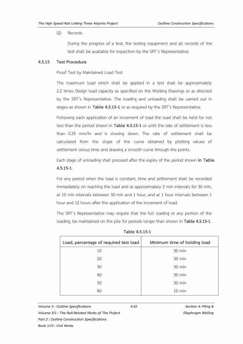
The High Speed Rail Linking Three Airports Project Outline Construction Specifications
Volume 3 : Outline Specifications 4-22 Section 4: Piling & Volume 3/1 : The Rail-Related Works of The Project Diaphragm Walling Part 2 : Outline Construction Specifications Book 1//2 : Civil Works
(2) Records
During the progress of a test, the testing equipment and all records of the test shall be available for inspection by the SRT’s Representative.
4.5.15 Test Procedure
Proof Test by Maintained Load Test
The maximum load which shall be applied in a test shall be approximately 2.2 times Design load capacity as specified on the Working Drawings or as directed by the SRT’s Representative. The loading and unloading shall be carried out in stages as shown in Table 4.5.15-1 or as required by the SRT’s Representative.
Following each application of an increment of load the load shall be held for not less than the period shown in Table 4.5.15-1 or until the rate of settlement is less than 0.25 mm/hr and is slowing down. The rate of settlement shall be calculated from the slope of the curve obtained by plotting values of settlement versus time and drawing a smooth curve through the points.
Each stage of unloading shall proceed after the expiry of the period shown in Table 4.5.15-1.
For any period when the load is constant, time and settlement shall be recorded immediately on reaching the load and at approximately 5 min intervals for 30 min, at 10 min intervals between 30 min and 1 hour, and at 1 hour intervals between 1 hour and 12 hours after the application of the increment of load.
The SRT’s Representative may require that the full loading or any portion of the loading, be maintained on the pile for periods longer than shown in Table 4.5.15-1.
Table 4.5.15-1
Load, percentage of required test load Minimum time of holding load 10 20 30 40 50 40
30 min 30 min 30 min 30 min 30 min 10 min
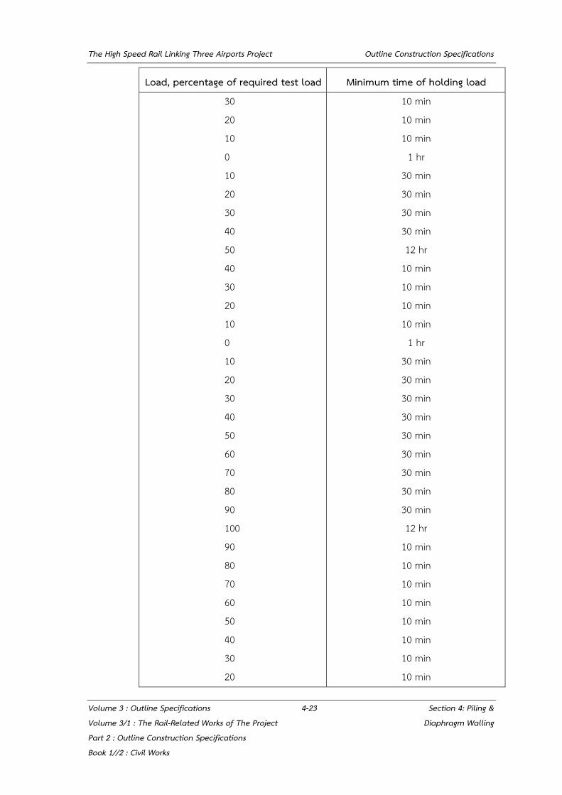
The High Speed Rail Linking Three Airports Project Outline Construction Specifications
Volume 3 : Outline Specifications 4-23 Section 4: Piling & Volume 3/1 : The Rail-Related Works of The Project Diaphragm Walling Part 2 : Outline Construction Specifications Book 1//2 : Civil Works
Load, percentage of required test load Minimum time of holding load 30 20 10 0 10 20 30 40 50 40 30 20 10 0 10 20 30 40 50 60 70 80 90 100 90 80 70 60 50 40 30 20
10 min 10 min 10 min
1 hr 30 min 30 min 30 min 30 min 12 hr
10 min 10 min 10 min 10 min
1 hr 30 min 30 min 30 min 30 min 30 min 30 min 30 min 30 min 30 min 12 hr
10 min 10 min 10 min 10 min 10 min 10 min 10 min 10 min
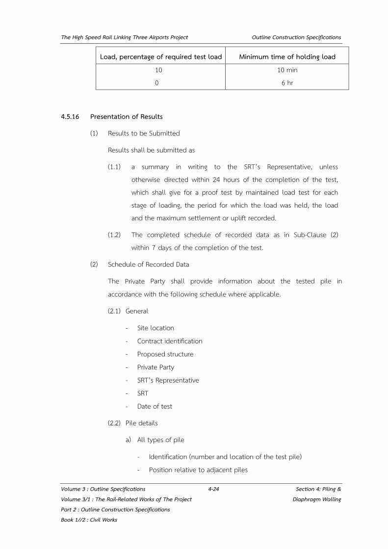
The High Speed Rail Linking Three Airports Project Outline Construction Specifications
Volume 3 : Outline Specifications 4-24 Section 4: Piling & Volume 3/1 : The Rail-Related Works of The Project Diaphragm Walling Part 2 : Outline Construction Specifications Book 1//2 : Civil Works
Load, percentage of required test load Minimum time of holding load 10 0
10 min 6 hr
4.5.16 Presentation of Results
(1) Results to be Submitted
Results shall be submitted as
(1.1) a summary in writing to the SRT’s Representative, unless otherwise directed within 24 hours of the completion of the test, which shall give for a proof test by maintained load test for each stage of loading, the period for which the load was held, the load and the maximum settlement or uplift recorded.
(1.2) The completed schedule of recorded data as in Sub-Clause (2) within 7 days of the completion of the test.
(2) Schedule of Recorded Data
The Private Party shall provide information about the tested pile in accordance with the following schedule where applicable.
(2.1) General
- Site location - Contract identification - Proposed structure - Private Party - SRT’s Representative - SRT - Date of test
(2.2) Pile details
a) All types of pile
- Identification (number and location of the test pile) - Position relative to adjacent piles

The High Speed Rail Linking Three Airports Project Outline Construction Specifications
Volume 3 : Outline Specifications 4-25 Section 4: Piling & Volume 3/1 : The Rail-Related Works of The Project Diaphragm Walling Part 2 : Outline Construction Specifications Book 1//2 : Civil Works
- Brief description of location (e.g. in cofferdam, in cutting, over water)
- Ground level at pile position - Head level at which test load is applied - Type of pile - Vertical or raking, compression or tension - Shape and size of cross-section of pile, position of change in
cross-section - Shoe or base details - Head details - Length in ground - Level of toe - Any permanent casing or core
b) Concrete piles
- Concrete mix - Aggregate type and source - Cement type - Slump - Cylinder test results for pile and cap - Date of casting of precast pile - Reinforcement
c) Steel piles
- Steel quality - Coating - Filing
(2.3) Installation details
a) All piles
- Dates and times of boring, driving and concreting of test pile and adjacent piles
- Unexpected circumstances and difficulties - Date and time of casting concrete pile cap
The High Speed Rail Linking Three Airports Project Outline Construction Specifications
Volume 3 : Outline Specifications 4-26 Section 4: Piling & Volume 3/1 : The Rail-Related Works of The Project Diaphragm Walling Part 2 : Outline Construction Specifications Book 1//2 : Civil Works
- Start and finish of each operation during driving or installation of a pile and subsequent testing
- Difficulties in handling, pitching and driving pile - Delays due to weather conditions - Method of placing concrete and conditions pertaining - Volume of concrete placed
b) Bored piles
- Type of equipment used and method of boring - Temporary casing, method of installation and extraction - Strata encountered during boring - Water encountered during boring - Concrete level before and after extraction of casing
c) Driven performed piles and piles driven in place
- Method of support of pile and hammer (frame, hanging leaders, suspended hammer or other method)
- Driven length of pile at final set - Hammer type, size or weight - Dolly and packing, type and condition before and after driving - Driving log (depth, blows per 250 mm., interruptions or breaks in
driving) - Final set in number of blows to produce penetration of 25 mm. - Redrive check, time interval and set in number of blows to
produce penetration of 25 mm. - At final set and at redrive set,
(i) for drop or single acting hammer the length of the drop or stroke,
(ii) for diesel hammer the length of the stroke and the blows per minute,
The High Speed Rail Linking Three Airports Project Outline Construction Specifications
Volume 3 : Outline Specifications 4-27 Section 4: Piling & Volume 3/1 : The Rail-Related Works of The Project Diaphragm Walling Part 2 : Outline Construction Specifications Book 1//2 : Civil Works
(iii) for double-acting hammer the number of blows per minute
- Condition of pile head after driving - Use of a follower - Use of preboring - Use of jetting - Lengthening - Method of placing concrete and conditions pertaining
(3) Test procedure
- Weight of kentledge - Tension pile, ground anchor or compression pile details - Plan of test arrangement showing position and distances of
kentledge supports, rafts, tension or compression piles and reference frame to test pile
- Jack capacity - Method of load measurement - Method(s) of penetration or uplift measurement - Proof test by maintained loading - Relevant dates and times
(4) Test results
- In tabular form - In graphical form: load plotted against settlement, load and settlement
plotted against times - Ground heave
(5) Site investigation
- Site investigation report number - Boredhole references
The High Speed Rail Linking Three Airports Project Outline Construction Specifications
Volume 3 : Outline Specifications 4-28 Section 4: Piling & Volume 3/1 : The Rail-Related Works of The Project Diaphragm Walling Part 2 : Outline Construction Specifications Book 1//2 : Civil Works
4.5.17 Completion of a Test
(1) Measuring Equipment
On completion of a test all equipment and measuring devices shall be dismantled, checked and either stored so that they are available for use in further tests or removed from the Site.
(2) Kentledge
Kentledge and its supporting structure shall be removed from the test pile and stored so that they are available for use in further tests or removed from the Site.
(3) Ground Anchors and Temporary Piles
On completion of a preliminary test, tension piles and ground anchors shall be cut off below level, removed from the Site and the ground made good with approved material as specified.
(4) Test Pile Cap
On completion of a test, the test pile cap, if formed in concrete, shall be broken off and the resulting material disposed of off the Site. If the pile cap is made of steel it shall be cut off and stored so that it is available for use in further tests or removed from the Site.
For pilot test piles which are not to be incorporated into the Permanent Works, they shall be broken down to 2 m below ground level or as required by the SRT’s Representative and backfilled to the original ground level with suitable material. For pilot test piles which are to be incorporated into the Permanent Works the pile head shall be made good or extended to the cut off level.
4.5.18 High Strain Dynamic Testing of Piles
High Strain Dynamic Testing in accordance with ASTM D4945-12 shall be carried out to estimate the bearing capacity of a pile. The maximum load which shall be applied in a test shall be approximately 1.5 times Design load capacity as specified on the Working Drawings or as directed by the SRT’s Representative. The Private Party shall submit for approval of testing procedure and shall provide sufficient evidence as required by the SRT’s Representative to validate the

The High Speed Rail Linking Three Airports Project Outline Construction Specifications
Volume 3 : Outline Specifications 4-29 Section 4: Piling & Volume 3/1 : The Rail-Related Works of The Project Diaphragm Walling Part 2 : Outline Construction Specifications Book 1//2 : Civil Works
proposed procedure. High Strain Dynamic Testing shall be carried out by an approved specialist firm.
Selected ram weight shall be sufficient to mobilize pile toe and shall be confirmed by Wave Equation Analysis of Pile (WEAP).
4.5.19 Lateral Load Tests
Lateral load tests, where required, shall be carried out using temporary plant capable of providing an unyielding reaction of at least 1.5 times the maximum lateral load to which the pile is to be tested. Test shall be carried out in accordance with ASTM D3966. The Private Party shall submit the type of test proposed to the SRT’s Representative for approval at least 2 weeks prior to construction of the pile.
Alternatively, where tension piles of the same size and type as the permanent piles are used for providing the reaction system for vertical loads tests, these may be used for the lateral load test by jacking apart. In this case they shall be provided with sufficient reinforcement to sustain the effects of maximum lateral load.
4.5.20 Horizontal Maintained Load Test
Trial piles shall be loaded to the specified proof load which is equal to 1.0 x the specified horizontal working load. The loading and unloading shall be carried out in stages as follows:
(1) Load the trial pile to the specified horizontal working load in 10 equal increments.
(2) Unload and re-load to the working load for not less than 10 cycles of loading and unloading and until the measured final movement at the end of each cycle is within 0.25 mm of the recorded movement at the end of each of the previous 4 cycles.
(3) Load the pile in increments of 1/10 of the working load to attain a load equal to the proof load.

The High Speed Rail Linking Three Airports Project Outline Construction Specifications
Volume 3 : Outline Specifications 4-30 Section 4: Piling & Volume 3/1 : The Rail-Related Works of The Project Diaphragm Walling Part 2 : Outline Construction Specifications Book 1//2 : Civil Works
(4) Unload the pile and measure the final movement when the movement rate has reduced to less than 0.25 mm/hr, measured over a minimum of 15 minutes.
The rate of application of horizontal load shall not exceed 20 kN per minute and each load increment shall be maintained constant until the rate of horizontal pile movement is reducing and does not exceed 0.25 mm/hr, measured over a minimum of 15 minutes.
Immediately prior to and during the final load test, at values of applied load equal to 0%, 20%, 40%, 60%, 80% and 100% of the specified horizontal working load, an inclinometer shall be lowered into a duct within each tested pile. Readings of pile inclination at each specified load shall be made at 2 m intervals reducing to 0.5 m intervals in the bottom 6 m of each pile. The same duct shall be used for all readings and at each interval readings shall be made in two mutually perpendicular directions.
For the purposes of establishing the pile inclination prior to the application of load 4 sets of readings shall be made.
4.5.21 Pile Integrity Tests
(1) The integrity of each pilot pile shall be examined prior to undertaking any pile load testing.
(2) The integrity of each working pile shall be examined prior to acceptance of the pile into the Permanent Works.
(3) Integrity testing shall be carried out by non-destructive test methods and by an approved specialist firm.
(4) For bored piles which are not tested to determine integrity by sonic logging test, High Strength Integrity Testing shall be employed. For Driven piles, the Low Strain Integrity Testing shall be carried out in accordance with ASTM D5882-16. The Private Party shall submit the type of test proposed to the SRT’s Representative for approval at least 2 weeks prior to construction of the pile.
(5) Unless otherwise approved, integrity tests shall not be carried out until 7 days or more have elapsed since pile casting.
The High Speed Rail Linking Three Airports Project Outline Construction Specifications
Volume 3 : Outline Specifications 4-31 Section 4: Piling & Volume 3/1 : The Rail-Related Works of The Project Diaphragm Walling Part 2 : Outline Construction Specifications Book 1//2 : Civil Works
(6) Testing shall be undertaken on pile heads before steel reinforcement for pile caps is placed.
(7) The pile head shall be clean and free from water at the time of testing. All laitance and contaminated concrete or concrete overspill shall be trimmed from each pile prior to the commencement of testing.
(8) The Private Party shall submit a method statement for the proposed tests, with technical information to demonstrate how the results obtained from the tests are to be interpreted in order that irregularities can be identified.
(9) The interpretation of test results shall be carried out by competent specialist SRT’s Representatives. The test results and associated interpretive report shall be provided to the SRT’s Representative within 10 days of the completion of each phase of testing.
- Any anomalies which are reported as a result of integrity testing shall, at the discretion of the SRT’s Representative, be investigated further. Such investigations shall be as directed by the SRT’s Representative.
- If such anomalies are shown to be detrimental to the performance of the pile, remedial measures shall be approved by the SRT’s Representative and undertaken by the Piling Private Party to rectify this.
- No covering over of the piles shall occur until the SRT’s Representative is satisfied with the results of the testing and any remedial works.
4.6 DIAPHRAGM WALLING
4.6.1 General
The recommendations of BS 8004 shall be followed insofar as they are applicable to diaphragm wall construction.
The attention of the Private Party is drawn to the fact that in some locations the walls may be close to existing structures and/or within a location where headroom is limited, and he shall take full account of such restrictions.

The High Speed Rail Linking Three Airports Project Outline Construction Specifications
Volume 3 : Outline Specifications 4-32 Section 4: Piling & Volume 3/1 : The Rail-Related Works of The Project Diaphragm Walling Part 2 : Outline Construction Specifications Book 1//2 : Civil Works
The Private Party shall pay particular attention to safety aspects of the work, employing barriers and covers as necessary.
4.6.2 Method Statement
The Private Party shall carry out the works in accordance with his method statement using the consented materials, plant and methods and with these Outline Construction Specifications.
4.6.3 Levels of Work
Diaphragm walls shall be constructed to the levels shown on the consented Working Drawings. Any remaining bentonite within the trench shall be removed to the satisfaction of the SRT’s Representative.
4.6.4 Width of Panels
The width of the panels to be concreted shall be defined in the Private Party's method statement and shall not normally be longer than 4.5 m, except where stability can be demonstrated by the Private Party.
4.6.5 Tolerances
Construction shall be carried out in accordance with the following tolerances, unless otherwise defined by the Working Drawings or procedures.
(1) The minimum clear distance between the faces of the guide walls shall be the specified diaphragm wall thickness plus 25mm, and the maximum distance shall be the specified diaphragm wall thickness plus 50mm. The guide walls shall be propped as necessary, to maintain these tolerances, and the inner guide wall shall be constructed to the line as shown on the Working Drawings.
The trench face of the guide wall on the side of the trench nearest to the subsequent main excavation shall be vertical to within 1:200. The top edge of this wall face shall not vary from a straight line or the specified profile by more than +15mm in 3m and shall be without ridges or abrupt irregularities.

The High Speed Rail Linking Three Airports Project Outline Construction Specifications
Volume 3 : Outline Specifications 4-33 Section 4: Piling & Volume 3/1 : The Rail-Related Works of The Project Diaphragm Walling Part 2 : Outline Construction Specifications Book 1//2 : Civil Works
(2) The plane of the wall face to be exposed shall be vertical to within a tolerance of 1:80, relative to a vertical line projected from the base of the guide wall. In addition to this tolerance, 75mm shall be allowed for protuberances resulting from irregularities in the ground excavated beyond the general face of the wall.
(3) The ends of panels shall be vertical to within a tolerance of 1: 80. (4) Where recesses are to be formed by inserts in the wall, they shall be
positioned within a vertical tolerance of 75mm, a horizontal tolerance measured along the face of the wall of 75mm, and a horizontal tolerance at right angles to the face of the wall as constructed of 75mm.
(5) The tolerance in positioning reinforcement shall be as follows: Longitudinal tolerance of cage head at the top of the guide wall and
measured along the trench: 75mm. Vertical tolerance at cage head in relation to the top of the guide wall:
5mm. Lateral tolerance of reinforcement position in the direction across the
width of the wall shall be 50mm. (6) The tolerance in positioning couplers and starter bars for subsequent
structural connections shall be as follows: Longitudinal tolerance measured along the trench: 75mm. Vertical tolerance: 50mm. Lateral tolerance in the direction across the width of panel shall be
50mm. (7) A minimum cover to reinforcement of 70mm shall be maintained. (8) Notwithstanding the requirements of this Clause the tolerances may be
aggregated only to the extent that they do not exceed 250mm. (9) The Private Party shall establish his worst accumulated out of tolerance
position for the diaphragm wall at the lowest slab level (track-slab) and use this to determine the position of the guide-walls at ground level.
(10) If, during the general excavation, it is detected that the above stated tolerances have been exceeded, the Private Party shall draw up proposals for remedying or compensating for the defects. The Private Party should review his method statement for all subsequent diaphragm wall construction.

The High Speed Rail Linking Three Airports Project Outline Construction Specifications
Volume 3 : Outline Specifications 4-34 Section 4: Piling & Volume 3/1 : The Rail-Related Works of The Project Diaphragm Walling Part 2 : Outline Construction Specifications Book 1//2 : Civil Works
4.6.6 Access
The Private Party shall note the restricted access to portions of the Works and shall satisfy himself that his method of excavation, spoil handling, placement of reinforcement cages, stop ends, and concreting can be accommodated within these restrictions.
4.6.7 Adjacent Properties
i) The Private Party shall be responsible for any damage or movement in adjacent utilities, buildings, highways and underground structures of any type.
ii) Allowance shall be made for all ancillary treatment and all work necessary to ensure the stability of roadworks, adjacent structures and underground constructions and utilities.
4.6.8 Reinforcement
Reinforcement shall comply with the requirements of Section 5. Front and rear of cages shall be marked on Site to identify them during placement, and lifting points and design of lifting lugs shall not cause distortion of the cage. Distance spacers shall be of an approved type, capable of resisting displacement during cage placement within the trench and shall not entrap slurry during cage placement or concreting. The reinforcement shall be adequately fixed to avoid displacement and to maintain the minimum specified cover during concreting.
4.6.9 Concrete
Concrete shall comply with the general requirements of Section 5. Structural concrete shall have a minimum cement content of 400kg/m³ where the concrete is being placed by tremie methods, in accordance with BS 8004. Minimum slump of the concrete shall be 150mm and the mix shall flow easily within the tremie pipe and be designed to produce a dense impervious concrete. Such structural concrete shall have a minimum compressive cube strength of 40 N/mm² at 28 days and the water: cement ratio of the mix shall not exceed 0.60 or as required by the design.
Lean mix concrete with an aggregate: cement ratio of 10:1 with a water:cement ratio between 0.65 and 0.7 shall be employed as backfill above any cut-off level for structural concrete and be taken to the top level of the guide walls.
The High Speed Rail Linking Three Airports Project Outline Construction Specifications
Volume 3 : Outline Specifications 4-35 Section 4: Piling & Volume 3/1 : The Rail-Related Works of The Project Diaphragm Walling Part 2 : Outline Construction Specifications Book 1//2 : Civil Works
4.6.10 Test Cylinders
Test cylinders shall be made and tested in accordance with Clause 5.2.3.2 Test cylinders shall be taken for each panel constructed. Cylinders shall be marked with the wall panel numbers and shall be sub-marked within each panel set to indicate a location within the panel.
4.6.11 Bentonite
Bentonite for use in the wall support slurry shall be in accordance with the requirements of Clause 4.4.3.
The Private Party shall institute a programme of regular sampling and testing to ensure that the bentonite fluid properties are suitable for the work.
4.6.12 Storage of Bentonite
Bentonite shall be stored in dry cool conditions. Particular care shall be taken with bulk storage to prevent balling together of bentonite powder due to damp, or deterioration of properties due to damp and heat. A suitable design of hopper cone and bentonite feeding device shall be adopted.
4.6.13 Alternative Materials
The Private Party may, subject to other requirements of the Specifications, consider and adopt suitable additional or alternative ingredients and additives for the wall support slurry to that of bentonite as specified above. Samples and full details shall be obtained from the supplier and manufacturer of such ingredients.
For example, if the Private Party proposes to use polymer fluid in place of bentonite, he shall produce an appropriate specification for the polymer, and a method statement for its use, and submit this to the SRT’s Representative for review and a statement of No Objection.
Any such materials shall have no detrimental effect upon the stability of the excavation or concreting, or formed concrete. Ingredients to counteract the loss of slurry to the surrounding strata shall be deemed covered by this Section.
The High Speed Rail Linking Three Airports Project Outline Construction Specifications
Volume 3 : Outline Specifications 4-36 Section 4: Piling & Volume 3/1 : The Rail-Related Works of The Project Diaphragm Walling Part 2 : Outline Construction Specifications Book 1//2 : Civil Works
4.6.14 Placing Concrete by Tremie
Tremie pipes shall be clean, watertight and with a minimum internal diameter of 250mm. The tremie tube shall extend to the bottom of the trench excavation prior to concreting and care shall be taken to ensure that all bentonite slurry is expelled from the pipe during the initial charging operation. The tremie pipe shall be maintained with a minimum embedment of 2.0m into the concrete to prevent the re-entry of slurry into the pipe. The Private Party shall ensure that an adequate supply of concrete to the tremie is available at all times so that placement is continuous until completion of the panel. The number of tremie pipes per panel shall be in accordance with the method statement. Where more than one tremie pipe is employed during concrete pouring to any one panel, the charging of concrete into the pipes shall be arranged so that it is evenly distributed between the pipes and so that no differential head exists at the concrete/slurry interface over the length of the panel. This level shall be confirmed by soundings taken during the concrete pour.
4.6.15 Stop Ends
Stop ends, inserted before placement of concrete in the panel, shall be clean and have a smooth regular surface. Any shutter release agent shall have no detrimental effect on the finished works. Where stop ends are inserted in sections, adequate joint connections must be provided to ensure verticality of the complete tube.
The extraction of stop ends shall be carried out at such a time and in such a manner that no damage is caused to the concrete placed against them, or to the adjacent soil and structures.
4.6.16 Inserts
Inserts shall be formed at the locations shown in the Working Drawings and in accordance with his method statements and procedures.
4.6.17 Checking and Monitoring
The Private Party shall provide all necessary monitoring instrumentation necessary for the close and continuous checking of the movements of adjacent structures, services and underground constructions.
The High Speed Rail Linking Three Airports Project Outline Construction Specifications
Volume 3 : Outline Specifications 4-37 Section 4: Piling & Volume 3/1 : The Rail-Related Works of The Project Diaphragm Walling Part 2 : Outline Construction Specifications Book 1//2 : Civil Works
4.6.18 Safety and Emergency Procedures
The Private Party shall take all necessary precautions to ensure stability of his excavations and guide walls and shall take all necessary precautions and be responsible for the safety of personnel in the area of operation. He shall maintain, available for immediate use, a sufficient quantity of slurry to allow for any sudden loss.
Should the loss continue despite the addition of the slurry and the stability of the trench be placed at risk, the Private Party shall backfill with lean mix concrete to preserve the stability of the trench and ensure the safety of neighbouring structures and utility services.
4.6.19 Site Cleanliness
The Private Party shall ensure that the Site is cleared of slurry and that surplus or displaced slurry is disposed of safely and without nuisance. All operations shall be conducted in such a manner as to minimise any spillage of slurry over the Site, or accesses thereto.
Works in public highways or footpaths shall be contained such that there is no spillage onto adjacent public areas.
4.6.20 Obstructions
An obstruction is defined as material, the excavation of which hinders normal progress and the existence of which could not have been foreseen. Upon encountering an obstruction, the Private Party shall determine the method to be employed in overcoming the obstruction. The Private Party is also requested to inform such obstruction and subsequent overcoming to the SRT’s representative accordingly.
4.6.21 Disposal of Spoil
i) Spoil removed from the excavation shall be separated from the slurry employed in the excavation process. It shall be disposed of as quickly as possible to an approved dump site and in such a manner that spillage and annoyance be minimized.
ii) Contaminated slurry, not suitable for re-use, shall be removed from the Site and disposed of in accordance with Clause 4.6.24 below.
The High Speed Rail Linking Three Airports Project Outline Construction Specifications
Volume 3 : Outline Specifications 4-38 Section 4: Piling & Volume 3/1 : The Rail-Related Works of The Project Diaphragm Walling Part 2 : Outline Construction Specifications Book 1//2 : Civil Works
4.6.22 Joints
Where concrete is cast against previously completed wall panels, the previously formed concrete shall be cleaned so that solid substances are removed before the joint is formed. When the joint is exposed upon subsequent excavation, the Private Party shall repair any joints which permit jetting or spraying of water or within which solid foreign substances greater than 3mm separate the concrete in adjacent panels. The walls formed shall be substantially watertight, that is, free from running or percolating water.
4.6.23 Records
The following records shall be kept for each wall panel and such records shall be available for inspection by the SRT’s Representative.
i) Panel No:
ii) Date and time of start of panel excavation;
iii) Date and time of finish of panel excavation;
iv) Details of any obstructions encountered;
v) Date and time of completion of cage placement;
vi) Date and time of start and completion of panel concreting;
vii) Length of panel and width and depth of panel from top of guide wall level;
viii) A log of soil type encountered from start to finish of excavation, and of slurry levels;
ix) Volume of concrete used and time of any interruptions in concrete supply where these exceed 15 minutes. Volumes of normal and lean mix concrete;
x) Cut-off level of concrete below top of guide wall level;
xi) Date, place and time of slurry control tests and results recorded;
xii) Concrete test cylinder, markings, date and results obtained on testing;
xiii) Details of reinforcement and cage type;

The High Speed Rail Linking Three Airports Project Outline Construction Specifications
Volume 3 : Outline Specifications 4-39 Section 4: Piling & Volume 3/1 : The Rail-Related Works of The Project Diaphragm Walling Part 2 : Outline Construction Specifications Book 1//2 : Civil Works
xiv) Quantity of slurry removed from Site and spoil removed from Site recorded by date;
xv) A graph of theoretical and placed concrete volumes with depth.
4.6.24 Disposal of Slurry
Used bentonite or contaminated slurry not suitable for re-use shall be disposed of in water-tight containers. The Private Party may propose alternative means of disposal which shall be subject to the agreement of the appropriate authorities.

The High Speed Rail Linking Three Airports Project Outline Construction Specifications
Volume 3 : Outline Specifications 5-1 Section 5: Concrete Volume 3/1 : The Rail-Related Works of The Project Part 2 : Outline Construction Specifications Book 1//2 : Civil Works
SECTION 5: CONCRETE
5.1 Concrete Materials
5.1.1 General
This work shall consist of the construction of all or portions of structures of Portland cement concrete, of the required class or classes, with or without reinforcement, and with or without admixture, be constructed in accordance with these Specifications and the lines, levels, grades, and dimensions shown on the consented Working Drawings, and as required by the SRT’s Representative.
Constituent materials shall, except where otherwise described in the Contract, comply with the requirement of BS 5328.
5.1.2 Cement
5.1.2.1 Cement general
Unless described otherwise in the Contract, cement shall comply with TIS Standard 15 Part 1-1971 Type 1. Types 2, 3 or 5 may be used if approved by the SRT’s Representative.
5.1.2.2 Cement testing
Cement shall be certified by the manufacturer as complying with the requirements of the TIS Standard. The Private Party shall submit to the SRT’s Representative the manufacturer's certificate to affirm that the cement complies with the relevant standard.
Before ordering cement, the Private Party shall submit details of the proposed supplier and information on the proposed methods of transport, storage and certification for approval and show that the quantity and quality required can be attained and maintained throughout the construction period. Representative samples of the proposed cement may be required to be taken and forwarded to an independent laboratory for analysis before the source is approved.
Subsequent to obtaining the SRT’s Representative's approval, the Private Party shall not change the agreed arrangements without the prior written approval of the SRT’s Representative. Each consignment of cement shall be accompanied by a

The High Speed Rail Linking Three Airports Project Outline Construction Specifications
Volume 3 : Outline Specifications 5-2 Section 5: Concrete Volume 3/1 : The Rail-Related Works of The Project Part 2 : Outline Construction Specifications Book 1//2 : Civil Works
certificate which shall be submitted to the SRT’s Representative immediately after delivery showing the place of manufacture and the results of standard tests carried out by the manufacturer. Additionally, the Private Party may be required to take samples of cement and test such samples in accordance with the relevant TIS or British Standard. The Private Party shall store the cement so that separate consignments can be identified and so that they are used in order of delivery.
5.1.2.3 Cement delivery and storage
Cement shall be delivered in bulk or in the original manufacturer's sealed and marked bags, and shall be protected from the weather by enclosed transfer systems or other approved coverings.
The Private Party shall provide approved silos to store sufficient bulk cement for continuity of work, and the cement shall be placed therein upon delivery. Approved precautions shall be taken to prevent cement dust causing a nuisance.
Cement that, in the opinion of the SRT’s Representative, has been damaged or does not comply with the specification shall not be used in the Works and shall be removed from the Site within 3 days of the Private Party's receipt of written notification of such opinion.
5.1.3 Aggregate
5.1.3.1 Aggregate sources
Prior to commencing any concrete work, the Private Party shall obtain the SRT’s Representative's consented to use the proposed types and sources of aggregate.
5.1.3.2 Coarse aggregate
Coarse aggregate for all classes of concrete shall conform to the requirements of AASHTO standard Specification M 80. It shall be furnished in two separate sizes; either the 20 mm to No. 4 and or the 38 mm to No. 4 as called for in the Specification.
Coarse aggregate for concrete shall be clean, free from dust and other deleterious material graded from 50 mm down.
All aggregates shall be stored in such a way that they shall be kept free from contact with deleterious matter and aggregates of different sizes shall be stored separately and in such a way that segregation is prevented.

The High Speed Rail Linking Three Airports Project Outline Construction Specifications
Volume 3 : Outline Specifications 5-3 Section 5: Concrete Volume 3/1 : The Rail-Related Works of The Project Part 2 : Outline Construction Specifications Book 1//2 : Civil Works
All aggregate stockpiles shall be shaded from direct sunlight by means of a roof of sufficient height to enable unimpeded access to plant. Spraying of aggregate stockpiles with water shall be undertaken if necessary. All aggregate hoppers shall be painted white.
5.1.3.3 Fine aggregate
Fine aggregate shall conform to the requirements of AASHTO Standard Specification M 6 or as consented to by the SRT’s Representative.
5.1.3.4 Alkali-silica reactivity
If aggregates contain any materials which are reactive with alkalis in any of the constituents of the concrete, or in water which will be in contact with the finished work, then the Private Party shall take samples of these materials every week. The Private Party shall ensure that the concrete mix complies with the requirements of this Specification regarding "Precautions against alkali-silica reaction in concrete". The results of the Private Party's weekly monitoring tests shall be submitted in writing to the SRT’s Representative.
5.1.3.5 Chloride content
The chloride content of aggregates shall be within the recommended limits stated in BS882 and the chloride content of the concrete mix shall be within the recommended limit of BS 8110. Chloride levels shall be determined daily in accordance with the methods described in BS 812.
5.1.3.6 Sulphate content
The total acid soluble sulphate content of the concrete mix, expressed as SO3, shall not exceed the recommended limit in BS 8110.
5.1.3.7 Storage
Aggregate shall be stored in concrete-based bins or on stages to prevent intermixing and the inclusion of dirt and foreign materials. Each size of aggregate shall be stored separately. Storage bins shall be emptied and cleaned regularly.
The High Speed Rail Linking Three Airports Project Outline Construction Specifications
Volume 3 : Outline Specifications 5-4 Section 5: Concrete Volume 3/1 : The Rail-Related Works of The Project Part 2 : Outline Construction Specifications Book 1//2 : Civil Works
5.1.4 Reinforcement
5.1.4.1 Steel for reinforcement
High-yield deformed bars shall conform to Thai Industrial Standard TIS 24 to the grade unless otherwise consented to by the SRT’s Representative. Rounded bar, if applicable, shall conform to TIS 20.
5.1.4.2 Tying wire
Tying wire shall be annealed mild steel of core diameter approximately 1.25mm complying with TIS 138.
5.1.4.3 Testing
The Private Party shall provide copies of the manufacturer's certificates of tests results relating to the steel reinforcement to be supplied, and shall additionally provide independent test results obtained from an approved laboratory in respect of samples taken from reinforcement delivered to the Site.
5.1.4.4 Storage and Protection
Steel reinforcement shall be stored in an approved manner above ground, on a concrete slab, under cover and racked as necessary for protection from aggressive elements.
5.1.5 Water
5.1.5.1 Water General
The Private Party shall make his own arrangements and obtain approval for the provision of fresh water for the manufacture of concrete. Testing shall be in accordance with AASHTO T26.
5.1.5.2 Quality
Water to be used for mixing concrete and mortar shall be fresh and free from sediment and dissolved or suspended matter which may be harmful and shall comply with the requirements of BS 3148. Water samples from the intended source of supply shall be taken for analysis before any concrete work is commenced, and at intervals throughout the duration of the Contract.

The High Speed Rail Linking Three Airports Project Outline Construction Specifications
Volume 3 : Outline Specifications 5-5 Section 5: Concrete Volume 3/1 : The Rail-Related Works of The Project Part 2 : Outline Construction Specifications Book 1//2 : Civil Works
5.1.6 Admixtures
5.1.6.1 Admixtures general
The use of plasticiser or set-retarding admixtures is encouraged for hot weather conditions and truck mixed concrete, however; the approval of the SRT’s Representative shall be obtained prior to using any admixture in any concrete mix.
Admixtures containing chlorides or other corrosive agents shall not be used. Admixtures shall conform to BS 5075 and BS 1014.
5.1.6.2 Quality
If admixtures are permitted they shall be used in the correct quantities. Approved equipment and methods shall be used for dispensing and incorporating the admixture in the concrete; the dispensing unit shall be designed so that the discharge of the admixture is visible.
The concrete tests described herein shall be conducted with the admixture incorporated to establish that specified strengths are achieved, and that densities are not reduced. If air- entraining agents are used the density shall not be reduced by more than 5%.
Set-retarding and water-reducing admixtures shall consist of ligno-sulphonate. Airentraining agents shall consist of neutralized vinsol resin.
5.1.7 Minimizing the Risk of Alkali-Silica Reaction (ASR) in Concrete
5.1.7.1 Precautions against ASR in concrete
Concrete mixes for use in the Permanent Works shall comply with one of the Clauses 5.1.7.2, 5.1.7.3 or 5.1.7.4. The Private Party shall notify the SRT’s Representative of his proposals for complying with this requirement.
5.1.7.2 The cementitious material shall have a reactive alkali content not exceeding a maximum value of 0.6% by mass when defined and tested in accordance with Clauses 5.1.7.5 to 5.1.7.11 inclusive.
5.1.7.3 The total mass of reactive alkali in the concrete mix shall not exceed 3.0 kg/m3 of concrete when defined, tested and calculated in accordance with Clauses 5.1.7.5 to 5.1.7.11 inclusive and 5.1.7.12 to 5.1.7.15 inclusive.

The High Speed Rail Linking Three Airports Project Outline Construction Specifications
Volume 3 : Outline Specifications 5-6 Section 5: Concrete Volume 3/1 : The Rail-Related Works of The Project Part 2 : Outline Construction Specifications Book 1//2 : Civil Works
5.1.7.4 The aggregate shall be classed as non-reactive in accordance with the definition in Clause 5.1.7.14.
5.1.7.5 Cementitious material (Hydraulic and latent hydraulic binders): Cementitious materials shall comply with TIS 15.
5.1.7.6 The term alkali refers to the alkali metals sodium and potassium expressed as their oxides.
The reactive alkali content of Portland cements to TIS 15 shall be defined as the percentage by mass of equivalent sodium oxide (Na2O) calculated from: %
equivalent Na2O = % acid soluble Na2O + 0.658 x (% acid soluble K2O)
5.1.7.7 The method used in determining the acid soluble alkali content of the materials to TIS 15 shall be in accordance with BS 4550: Part 2: Clause 16.2.
5.1.7.8 The Private Party shall make available the certified average acid soluble alkali content of Portland cement to TIS 15 on a weekly basis.
5.1.7.9 The Private Party shall give immediate notice of any change which may increase the certified average acid soluble alkali content above the level used in the mix design for the concrete. A revised mix design for any concrete which would be affected by the increased alkali content shall be submitted for approval with notification of the change.
5.1.7.10 Minimising the Risk by Using Cementitious Material Containing less than 0.6% Reactive Alkali
The requirements of Clause 5.1.7.2 will be met by Clause 5.1.7.11 provided that the contribution of alkalis from other sources does not exceed 0.2 kg/m3 (see Clauses 5.1.7.14 and 21). Where these alkalis exceed 0.2 kg/m3 the requirements of Clauses 5.1.7.12 to 15 shall apply.
5.1.7.11 The cementitious material shall be Portland cement complying with TIS 15 and shall have additionally a certified maximum acid soluble alkali content not exceeding 0.6%.
The Private Party shall provide on request weekly certificates which name the source of the cement and confirm compliance with the Specification.
The High Speed Rail Linking Three Airports Project Outline Construction Specifications
Volume 3 : Outline Specifications 5-7 Section 5: Concrete Volume 3/1 : The Rail-Related Works of The Project Part 2 : Outline Construction Specifications Book 1//2 : Civil Works
5.1.7.12 Minimising the Risk by Limiting the Reactive
Alkali Content of the Concrete to 3.0 kg/m3
The requirements of Clause 5.1.7.3 will be met provided that Clauses 5.1.7.13, 14 and 15 are satisfied.
5.1.7.13 The reactive alkali content of the concrete contributed by the Portland cement to the concrete shall be calculated from: Portland cement
A = (Cxa)/100
where
A = reactive alkali content of the concrete to the nearest 0.1 (kg/m3)
C = target mean Portland cement content of the concrete (kg/m3)
a = certified average acid soluble alkali content of the Portland cement (%).
5.1.7.14 Where reactive alkalis in excess of 0.2kg/m3 are contributed to the concrete from sources other than the cementitious material the limit of 3.0 kg/m3 from the cementitious material shall be reduced by the total amount so contributed.
The reactive alkali contributed by sodium chloride contamination of aggregates shall be calculated from:
H = {0.76 [(NFxMF) + (NCxMC)]}/100
H = equivalent alkali contribution made to the concrete by the sodium chloride (kg/m³)
NF = chloride ion content of the fine aggregate as a percentage by mass of dry aggregates and measured according to BS 812: Part 4: 1976 (now in draft as Part 117)
MF = fine aggregate content (kg/m3)
NC = chloride ion content of the coarse aggregate as a percentage by mass of dry aggregate and measured according to BS 812: Part 4: 1976 (now in draft as Part 117)
MC = coarse aggregate content (kg/m3).

The High Speed Rail Linking Three Airports Project Outline Construction Specifications
Volume 3 : Outline Specifications 5-8 Section 5: Concrete Volume 3/1 : The Rail-Related Works of The Project Part 2 : Outline Construction Specifications Book 1//2 : Civil Works
The factor 0.76 is obtained from a consideration of the composition of sea water. The chloride ion content of aggregate sources containing 0.01% of chloride ion by mass or more shall be determined weekly in accordance with BS 812 or another approved method. When the chloride ion level is less than 0.01% it shall be regarded as nil.
5.1.7.15 The Private Party shall provide certificates on request confirming compliance with the Specification and stating:
(a) The target mean cementitious material content of the concrete.
(b) The names of the works manufacturing the cement.
(c) A weekly report of the cement alkali determinations in accordance with Clause 5.1.7.
(d) The certified average acid soluble alkali content of the Portland cement.
5.1.7.16 Minimising the risk by using selected aggregates
Fine and coarse aggregate material shall comply with the requirements of AASHTO Standard Specifications M6 and M80 respectively.
5.1.7.17 Water
Water for use in the manufacture of concrete shall be obtained from a public utility undertaking supply and shall be of potable quality.
5.1.7.18 Where a potable mains supply is not available the Private Party shall obtain confirmation of the quality and reliability of the proposed source from the appropriate water authority and shall thereafter seek consent from the SRT’s Representative to use the proposed source.
5.1.6.19 Water other than from a public utility undertaking supply shall be sampled at a frequency to be determined by the SRT’s Representative and tested in accordance with the relevant provisions of BS 3148. The sodium oxide and potassium oxide content shall be declared and expressed as equivalent Na2O and shall be taken into account when calculating the total reactive alkali content of the concrete mix.

The High Speed Rail Linking Three Airports Project Outline Construction Specifications
Volume 3 : Outline Specifications 5-9 Section 5: Concrete Volume 3/1 : The Rail-Related Works of The Project Part 2 : Outline Construction Specifications Book 1//2 : Civil Works
5.1.7.20 Admixtures and pigments
Admixtures and pigments shall comply with the requirements of BS 5075 and BS 1014. The manufacturer's declared equivalent acid soluble alkali content and the dosage rate of any admixture or pigment to be incorporated shall be included with details of all concrete mixes submitted for consent.
5.1.7.21 The alkali content of admixtures shall be taken into account when determining the total equivalent alkali content of the concrete mix.
5.2 CONCRETE WORKMANSHIP
5.2.1 Grade
5.2.1.1 Mixes general
Concrete shall be provided in accordance with BS 5328 except where required otherwise by this Specification.
5.2.1.2 Concrete mixes
The concrete mixes to be used in the Permanent Works shall be tabulated in the form as given in the Table of Concrete Mixes below. The "Type of Mix" (P, SP, or D) shall be as defined in BS 5328.
Table of Concrete Mixes
Note: to be completed by the Private Party
Description used on Drawings
Type of MIX Type of Cement.
Type of Aggregate. - Coarse
- Fine
Nominal Aggregate maximum size (mm) Grade
Minimum cement content (kg/m3)
Sampling rate (m3) - 28 day normal curing
- 7 day normal curing

The High Speed Rail Linking Three Airports Project Outline Construction Specifications
Volume 3 : Outline Specifications 5-10 Section 5: Concrete Volume 3/1 : The Rail-Related Works of The Project Part 2 : Outline Construction Specifications Book 1//2 : Civil Works
Workability - Slump (mm)
- VB(s)
- Compacting
Maximum free water/cement ratio
Maximum cement content (kg/m3)
Special cement
Special aggregate. Coarse:
Fine:
Fine aggregate (%)
Admixtures. Specified:
Prohibited:
Amount:
Air content
Temperature of Maximum:
Fresh concrete (ºC) Minimum:
Density of Concrete Maximum:
(kg/m3) Minimum:
5.2.1.3 Chlorides
The total chloride content of the concrete mix shall be in accordance with the limitations given in BS 8110 Clause 6.2.5.2.
5.2.1.4 Sulphates
The total water soluble sulphate content of the concrete mix shall not exceed the limitations given in BS 8110 Clause 6.2.5.3.

The High Speed Rail Linking Three Airports Project Outline Construction Specifications
Volume 3 : Outline Specifications 5-11 Section 5: Concrete Volume 3/1 : The Rail-Related Works of The Project Part 2 : Outline Construction Specifications Book 1//2 : Civil Works
5.2.2 Trial Mixes
5.2.2.1 Laboratory trials
Not less than 35 days before commencement of concreting, the Private Party shall carry out trials jointly with the SRT’s Representative to determine the concrete mixes which will satisfy the Specification. The materials and conditions used shall reflect those intended to be used for the Works. Six test cubes shall be made from each of three consecutive batches, three cubes to be tested at 7 days and three at 28 days. If the average 28 day strength being defined as the measured stress when the cube fails, exceeds the specified characteristic strength by 20 percent or more, and the other requirements of BS 5328 are met, then the trial mix proportions may be used to commence the Permanent Works. Otherwise further trials shall be carried out using re-designed mixes until the required strength is achieved.
Additional Requirements Trial mixes shall be tested to determine the following properties of mixes proposed for initial field tests:-
(a) Bleeding in accordance with ASTM C232.
(b) Drying shrinkage in accordance with BS 1881.
(c) Air content if applicable.
(d) Free water/cement ratio.
(e) Workability.
(f) Wet and dry densities.
(g) Indirect tensile strength in accordance with BS 1881 including cylinder – splitting and beam tests.
If the values obtained are unacceptable, the mixes shall be re-designed.
5.2.2.2 Initial field tests
Trial mixes shall be prepared under full-scale site conditions and tested in accordance with BS 1881.
Samples of concrete incorporating the reinforcing details to be used shall be cast and examined, before hardening using hand tools, and after hardening by coring to assess the mixes. Cores shall be 150mm dia. by 200 mm long.

The High Speed Rail Linking Three Airports Project Outline Construction Specifications
Volume 3 : Outline Specifications 5-12 Section 5: Concrete Volume 3/1 : The Rail-Related Works of The Project Part 2 : Outline Construction Specifications Book 1//2 : Civil Works
5.2.3 Quality Control
5.2.3.1 Test cubes piece
Cubes shall be manufactured in an on-site laboratory, specially equipped for the purpose, in controlled conditions. They shall be made, cured, stored, transported and tested to BS1881 ASTM C39, C873. The method of compacting cubes shall be as approved.
The cube-testing machine shall be housed in a laboratory and calibrated to BS 1610 when delivered; the calibration shall be verified at 3-monthly minimum intervals by an approved testing authority.
5.2.3.2 Sampling cubes test piece
A sample of concrete shall be taken at random on eight separate occasions during each of the first five days of using a mix. The standard deviation shall be calculated from at least 25 individual cube results each representing separate batches of similar concrete produced by the same plant under the same supervision. The margin for the plant shall be 1.64 times the standard deviation.
Thereafter one sample shall be taken at random for each class of concrete from every group of 25 batches made by each batching plant, and at least one sample shall be taken each day that concrete of a particular grade is made.
Samples shall also be taken and two cylinders cast to determine the indirect tensile strength of the concrete at 7 days and 28 days, as specified in BS 1881. These samples shall be taken from every 100 batches, but at least once a week during concreting operations, and shall coincide with samples taken for test cubes.
The frequency of sampling may be required to be varied.
In addition to the above requirements, at least one sample shall be taken from each individual structural unit, or part of a unit, when the latter is the product of a single pour. From each sample two cubes shall be made for testing at 28 days and one for testing at 7 days for control purposes. The 28 day Concrete Cube Strength (CCS) shall be the mean of two cubes.
The procedures shall be repeated when materials or design mixes are changed.
The High Speed Rail Linking Three Airports Project Outline Construction Specifications
Volume 3 : Outline Specifications 5-13 Section 5: Concrete Volume 3/1 : The Rail-Related Works of The Project Part 2 : Outline Construction Specifications Book 1//2 : Civil Works
5.2.3.3 Cube strength results
The results will be unacceptable if:
(i) the average strength determined from any four consecutive test cubes does not exceed the specified CCS by 0.5 times the current margin, or
(ii) one or more values in forty is less than 85% specified CCS, or
(iii) three or more values in forty are less than specified CCS; and any of the following actions may be instructed:-
(a) Changing the mix.
(b) Improving quality control.
(c) Cutting and testing cores from placed concrete.
(d) Load-testing relevant structural units.
(e) Non-destructive testing of placed concrete.
(f) Cutting-out and replacing defective concrete.
If the range of individual cube strength made from the same sample exceeds 15% of the mean then the method of making, curing and testing cubes shall be checked. In the event of a result having a range exceeding 20% the result shall be unacceptable and the SRT’s Representative may order any of the actions outlined in sub-clauses 5.2.3.3 (a) to (f).
In the event of (c) the Private Party shall cut cores from approved locations, and test them to BS 1881 ASTM C39, C873as modified by Concrete Society Report TR 11. If the values, reduced by 0.69 N/mm² per week of age in excess of 28 days, are less than 75% CCS, the concrete shall be removed unless otherwise consented to.
5.2.3.4 Other tests
Concrete shall be tested for drying shrinkage, water absorption and moisture movement as directed for which 102mm cubes and 76mm x 76mm prisms shall be prepared and tested in accordance with BS 1881.

The High Speed Rail Linking Three Airports Project Outline Construction Specifications
Volume 3 : Outline Specifications 5-14 Section 5: Concrete Volume 3/1 : The Rail-Related Works of The Project Part 2 : Outline Construction Specifications Book 1//2 : Civil Works
The acceptable limits are:-
Water absorption : 3% absorbed after 10 mins;
6.5% absorbed after 24 hours.
Drying shrinkage : 0.05%
Moisture movement: 0.03%
Cubes may be required and trials carried out to determine stripping times for formwork, the duration of curing and to check testing and sampling errors.
The air content of air-entrained concrete shall be determined for each batch produced until consistency has been achieved, when fewer batches may be tested.
During permanent works concreting six 150mm dia. 200mm long cores shall be cut through horizontal reinforcement to assess plastic qualities. The qualities shall be equal to those obtained in the initial field tests.
Compaction factor, slump, or other workability tests shall be carried out as required during concreting of permanent works to control workability at the batching plant at the site of the pour. The degree of workability shall be as for the trial mixes; permitted tolerances shall be in accordance with BS 5320.
Tests shall be carried out at least daily for the moisture content and weekly for absorption value of the aggregate. The values for the aggregate at the mixer shall be determined and changes made to the mix to compensate for variations.
5.2.4 Batching
5.2.4.1 Machinery
Batching shall be by wet batching machines equipped with accuracy checks for the weighing mechanism. The machines shall be cleaned, checked and adjusted regularly.
The water supply to the concrete mixers shall have a metering system to control and record the amount.
The High Speed Rail Linking Three Airports Project Outline Construction Specifications
Volume 3 : Outline Specifications 5-15 Section 5: Concrete Volume 3/1 : The Rail-Related Works of The Project Part 2 : Outline Construction Specifications Book 1//2 : Civil Works
5.2.4.2 Accuracy of batching
Batched materials shall be measured out within the following tolerances and discharged into the mixer without loss:-
Cement ± 2% of the weight of the cement in the batch.
Aggregate ± 2% of the weight of each aggregate in the batch.
Water ± 2% of the weight of water added to the batch.
Admixture ± 5% of the amount to be added to the batch.
5.2.4.3 Calibration of measuring equipment
Measuring equipment shall be checked and calibrated at the start of preliminary concrete tests and at weekly intervals. The necessary test weights and the like shall be kept available on site.
Scales shall be checked over their complete range by a specialist every three months. A calibrated container shall be used to check the accuracy of admixtures dispensers once each month. The results of these checks shall be notified.
5.2.4.4 Mixing
Concrete constituents shall be thoroughly mixed in batches. The machines shall be capable of discharging while running.
Ready-mixed concrete shall not be used unless approved, and shall comply with the requirements specified herein and those of BS 5328.
The supply and use of ready mixed concrete shall be subject to the Private Party's Quality Assurance procedures. It shall be obtained from a depot consented to by the SRT’s Representative. The concrete shall be transported to the Site in truck type mixers and shall be continuously agitated. The concrete shall be placed in its final position and compacted within 2 hours of the introduction of cement to the aggregates.
The concrete delivered to the Works shall comply with this Specification. 1 m³ of each mix shall be supplied to site before it is required in the Works to allow the Private Party to carry out workability tests. The supply and delivery of the ready-mixed concrete shall comply with the recommendations of BS 5328 Clause 7.4. For
The High Speed Rail Linking Three Airports Project Outline Construction Specifications
Volume 3 : Outline Specifications 5-16 Section 5: Concrete Volume 3/1 : The Rail-Related Works of The Project Part 2 : Outline Construction Specifications Book 1//2 : Civil Works
plant-mixed concrete the delivery note for each batch shall state the time at which the concrete was mixed and the weight of the constituents of each mix.
When truck-mixed concrete is used, water shall only be added under supervision either at the Site or at the central batching plant in accordance with the Quality Procedures. In no circumstances shall extra water be added to the concrete after the original mixing is complete.
Samples for work tests shall be taken as the concrete is placed in its final position.
The Private Party shall arrange for the supplier to provide the facilities stated in BS 5328 Clause 7.1 or 13.1.
5.2.4.6 Records
Daily returns shall be provided showing the quantities of cement and the total volume batched of each class of concrete for each section of the Works and temporary works. The Private Party shall submit detailed records of all test cubes and specimens taken and without delay submit the test results to the SRT’s Representative.
5.2.5 Control of Chlorides and Sulphates
5.2.5.1 Chlorides in concrete
The levels of equivalent acid-soluble chlorides as NaCl (Cl x 1.65 = NaCl) in the constituents of concrete as stated elsewhere are indicative and are subject to the overriding limits for the mixes.
The total estimated content as a percentage by weight of the cement in the mix shall not exceed the following limits:-
(a) For reinforced concrete
0.5% if made with Ordinary Portland Cement (OPC)
0.1% if made with Sulphate Resistant Portland Cement (SRPC)
(b) For mass concrete
1.0% if made with OPC
0.2% if made with SRPC

The High Speed Rail Linking Three Airports Project Outline Construction Specifications
Volume 3 : Outline Specifications 5-17 Section 5: Concrete Volume 3/1 : The Rail-Related Works of The Project Part 2 : Outline Construction Specifications Book 1//2 : Civil Works
The Private Party shall test the constituents of the concrete to establish these contents as provided for elsewhere in this Specification.
In addition, regular tests to BS 1881: Part 6 for chloride content shall be made on the hardened concrete. The following values are acceptable:-
(i) For reinforced concrete made with OPC
95% of the test results less than 0.40% NaCl by weight of cement and no result greater than 0.50% NaCl by weight of cement.
(ii) For reinforced concrete made with SRPC
95% of the test results less than 0.1% NaCl by weight of cement and no result greater than 0.14% NaCl by weight of cement.
(iii) For mass concrete made with OPC
95% of the test results less than 1.0% NaCl by weight of cement, and no result greater than 1.30% NaCl by weight of cement.
(iv) For mass concrete made with SRPC 95% of the test results less than 0.2% NaCl by weight of cement and no result greater than 0.25% NaCl by weight of cement.
In the event that the SRPC used contains a proportion by weight of tri-calcium aluminate which approaches 4 - 8%, then approval may be sought for an appropriate adjustment of the relevant chloride content limits.
5.2.5.2 Sulphates in concrete
The level of acid-soluble sulphates (SO3) in the mix shall be no greater than:
Coarse aggregate 0.4% by weight Fine aggregate 0.4% by weight Water 500 mg/l
The total estimated sulphate content (SO3) of the mix including that present in the cement shall not exceed 3.7% by weight of cement in the mix.
In addition, regular tests to BS 1881: Part 6 shall be made on the hardened concrete to determine the total sulphate content, which shall not exceed 4% by weight of cement in the mix.
The High Speed Rail Linking Three Airports Project Outline Construction Specifications
Volume 3 : Outline Specifications 5-18 Section 5: Concrete Volume 3/1 : The Rail-Related Works of The Project Part 2 : Outline Construction Specifications Book 1//2 : Civil Works
5.2.5.3 Permissible level of chloride and sulphates
The permissible level of chlorides and sulphates quoted in the above clauses shall not be considered as mean values for the whole of the Works, but shall apply to any concrete.
5.2.6 Placing
5.2.6.1 Placing general
Concrete shall be placed in the position and sequence indicated on the consented Working Drawings, or as directed. Placing shall not be commenced until the fixing and condition of reinforcement and items to be embedded and the condition of the containing surfaces or formwork has been approved. 24 hours written notification shall be given of the intention to place concrete.
Concrete shall be transported by means which prevent contamination (by dust, rain etc.) segregation or loss of ingredients, and shall be transported and placed without delay.
Concrete shall be placed directly in its final position without segregation or displacement of the reinforcement, embedded items and formwork. Concrete shall not be placed in water, except as specified. Concrete shall not be dropped through a height greater than 1.5 metres.
5.2.6.2 Extent of pours
The limit of individual pours and the height of lifts shall be as approved.
For walls, the length of panel placed at one time shall not exceed 6m; adjacent panels shall not be placed within 2 days, but shall be placed as soon as practicable thereafter. Subsequent vertical lifts shall not be poured within 2 days.
Floors, roofs and ground slabs shall be placed in a sequence of pours to the approval of the SRT’s Representative.
If the use of slip-forms or paving trains is permitted, these limits may be revised.
The sequence of pours shall be arranged to minimise thermal and shrinkage strains.
The High Speed Rail Linking Three Airports Project Outline Construction Specifications
Volume 3 : Outline Specifications 5-19 Section 5: Concrete Volume 3/1 : The Rail-Related Works of The Project Part 2 : Outline Construction Specifications Book 1//2 : Civil Works
5.2.6.3 Placing equipment
Concrete shall generally be placed without segregation by pumping or bottom-opening skips. If chutes are used their slopes shall not cause segregation and spouts or baffles shall be provided.
5.2.6.4 Time for placing
Concrete and mortar must be placed and compacted within 30 minutes of water being added to the mix or otherwise included via damp aggregates, unless admixtures are in use. Partially-set concrete shall not be used in the Works.
5.2.6.5 Compaction
Concrete shall be compacted during placing by approved internal vibrators. The vibrators shall operate at a frequency of not less than 8,000 cycles per minute, and shall be designed for continuous operation. The performance of vibrators shall suit the working conditions, and they shall generally not be less than 75mm diameter. The radius of influence shall ensure that the mass under treatment is compacted at a speed commensurate with the rate of supply of concrete.
5.2.6.6 Vibrators
Vibrators shall penetrate the full depth of the layer of concrete placed and just into the layer below, and be withdrawn slowly to avoid the formation of voids.
Vibration shall not be applied directly or indirectly to concrete after the initial set has taken place, nor shall it be used to make concrete flow in formwork.
The Private Party shall have a minimum of two spare vibrators available during each concrete pour in case of mechanical breakdowns.
5.2.6.7 Continuity of placing
Placing in each section of work shall be continuous between construction joints.
The Private Party shall make provision for standby equipment. If the placing of concrete is suspended due to plant breakdown or any incidents, then the Private Party shall provide vertical stop-ends to form a construction joint or remove the concrete already placed and restart after repair of the breakdown, as directed.
The High Speed Rail Linking Three Airports Project Outline Construction Specifications
Volume 3 : Outline Specifications 5-20 Section 5: Concrete Volume 3/1 : The Rail-Related Works of The Project Part 2 : Outline Construction Specifications Book 1//2 : Civil Works
5.2.6.8 Placing in inclement weather
Placing shall not take place in the open during storms or heavy rains. If such conditions are likely to occur the Private Party shall avoid to start the concrete placing operation. However, in order to prepare for unforeseen unfavorable weather, the Private Party shall provide protection for the materials, plant and formwork so that work may proceed. If strong winds are prevalent protection from driving rain and dust shall be provided.
5.2.6.9 Placing in high temperature and low temperature
The temperature of concrete shall not exceed 32ºC or the temperature stated in the table of Mixes whichever is the lower at the time of placing and the maximum concrete temperature after placing shall not exceed 50ºC or 30ºC above the concrete temperature at the time of placing whichever is the lower.
"Specification for Hot Weather Concreting" in the 2014 edition of ACI 305.1 shall be complied with. The following measures inter alia may be required to control the placing temperature:
(i) Shade aggregate, cement silos, water tanks and concrete plant.
(ii) Paint concrete plant white.
(iii) Run concrete plant with flake ice before mixing or transporting concrete.
(iv) Use chillers to cool the mixing water.
(v) Add flake ice as a proportion of the mixing water.
(vi) Place concrete at night.
(vii) Use plasticizing and retarding admixtures in an approved manner.
The Private Party shall supply suitable maximum/minimum thermometers and record the shade and sun temperatures at locations where concrete is being placed.
5.2.6.10 Placing at night
If consent has been given for placing at night or in dark interiors, adequate lighting shall be provided where mixing, transportation and placing are in progress.
The High Speed Rail Linking Three Airports Project Outline Construction Specifications
Volume 3 : Outline Specifications 5-21 Section 5: Concrete Volume 3/1 : The Rail-Related Works of The Project Part 2 : Outline Construction Specifications Book 1//2 : Civil Works
5.2.6.11 Placing under water
Underwater concrete shall be placed with minimum disturbance by the water. Running water and wave wash shall be controlled. The specified concrete grade shall be used and the mix design shall provide for good workability.
Tremie pipes, bottom-dump skips or other approved placing equipment shall be used to avoid the segregation.
Placing shall be commenced in approved sections and shall be continued to the completion.
The end of tremie pipe shall be kept extended into the concrete and the pipe must not be emptied until the pour is complete. If a bottom-dump skip is used, the contents shall be covered by canvas or similar before lowering into the water. The doors shall be opened when the skip is resting on the bottom with no tension in the support cable, and the skip shall be lifted gradually so that the concrete flows out steadily.
5.2.6.12 Preparation before placing
Before placing concrete for reinforced work on the ground, the formation shall be compacted as specified and a screed of blinding concrete shall be applied to form a surface for construction.
Before placing concrete on or against rock, masonry, brickwork or old concrete, loose material shall be removed and the surface washed down; water seepage shall be stopped or channelled away from the work.
For mass concrete placed against masonry or brickwork the following shall apply:-
(i) The mortar joints in the face against placed concrete shall have fully hardened.
(ii) The water-cement ratio of the concrete shall be increased to compensate for the absorption of moisture by the existing work.
(iii) The surface shall be soaked prior to placing.
(iv) The concrete shall be worked around ties and bond stones and into open joints.
The High Speed Rail Linking Three Airports Project Outline Construction Specifications
Volume 3 : Outline Specifications 5-22 Section 5: Concrete Volume 3/1 : The Rail-Related Works of The Project Part 2 : Outline Construction Specifications Book 1//2 : Civil Works
5.2.7 Formwork
5.2.7.1 Formwork general
The Private Party shall obtain approval of the methods and materials proposed. Details of formwork for special finishes shall be approved before materials are ordered. Formwork shall provide concrete of the shape, lines and dimensions shown on the consented Working Drawings.
Formwork shall be constructed from materials of sufficient strength, supported to provide rigidity during placing and compacting concrete without discernible deflection and shall be removable without disturbing the concrete. Internal ties shall be metal. Removable ties shall be located so that the specified cover to reinforcement is maintained to all surfaces including that of the tie-holes. If ties are left in the cover, they shall be as specified for the reinforcement or as approved. Tie cavities shall be roughened and filled with approved non-shrink concrete or epoxy mortar.
Formwork panels shall have true edges for accurate alignment and shall be fixed with either vertical or horizontal joints. Where chamfers are required the fillets shall be cut to provide an even line. Joints shall not permit leakage of grout, nor steps and ridges in exposed surfaces. Due allowance shall be made for deflection of formwork during concrete placement.
5.2.7.2 Wrought formwork
Wrought formwork shall be steel, Glass Reinforced Plastic (GRP) or lined plywood to produce a fine finish. Lining to plywood shall be clear-lacquered extra-hard hardboard. Where formwork is required and unless stated, wrought formwork shall be used to produce a fine finish.
5.2.7.3 Rough formwork
Rough formwork shall be butt-jointed, seasoned, sawn timber.
5.2.7.4 Preparation of formwork for concreting
Formwork and supports shall be cleaned; temporary openings shall be provided for the removal of rubbish. The formwork shall be coated with an approved mould release agent, and any excess of agent shall be removed. Release agent shall not

The High Speed Rail Linking Three Airports Project Outline Construction Specifications
Volume 3 : Outline Specifications 5-23 Section 5: Concrete Volume 3/1 : The Rail-Related Works of The Project Part 2 : Outline Construction Specifications Book 1//2 : Civil Works
be allowed to come into contact with concrete already placed or with reinforcement.
Not less than 24 hours notice shall be given for the inspection and approval of the formwork and reinforcement, prior to the commencement of placing concrete.
5.2.7.5 Removal of formwork
Formwork shall be removed without damage to the concrete, but shall not be removed until the concrete has sufficient strength to support itself. Centres and props may be removed when the member has sufficient strength to carry itself and any loading with a reasonable factor of safety. External loading shall not be applied until the concrete has reached the 28-day CCS unless otherwise approved by the SRT’s Representative. Formwork shall not be removed without prior approval.
The following is a guide to the minimum periods between placing and the removal of formwork:-
After removal remedial work shall not be undertaken until the concrete has been inspected and approved by the SRT’s Representative.
Vertical sides of beams, walls, columns
- Lift not exceeding 1.2m
- Lift exceeding 1.2m (but see Curing and Protection Clause 5.2.10) Soffits of main slabs and beams
- Props left under Beams and main slabs
- Removal of props
12 hrs. 36 hrs.
5 days
18 days

The High Speed Rail Linking Three Airports Project Outline Construction Specifications
Volume 3 : Outline Specifications 5-24 Section 5: Concrete Volume 3/1 : The Rail-Related Works of The Project Part 2 : Outline Construction Specifications Book 1//2 : Civil Works
5.2.8 Reinforcement
5.2.8.1 Reinforcement general
Steel rod reinforcement shall be cut, bent and fixed to BS 8110: Part 1. Cold bending shall be used which does not damage the material. Bending hot at a cherry-red heat not exceeding 840ºC may be approved except for bars dependent on cold-working for strength. Bars shall not be cooled by quenching.
5.2.8.2 Fixing
The number, size, form and position of pieces of reinforcement shall be as shown on the consented Working Drawings. They shall be held in position in the formwork during the placing of concrete by use of distance pieces and spacer bars.
Links shall be taut so that bars are braced and the inside of their curved parts shall be in contact with the bars being connected. Tying wire shall be twisted tight with pliers and the free ends shall be bent inwards.
Reinforcement temporarily projecting from the concrete at joints shall not be bent out of position without approval. In the event that the reinforcement shall be bent, a suitably sized former shall be used to prevent any damage or over-stressing.
5.2.8.3 Bending schedules
The Private Party shall provide drawings detailing the reinforcement required and shall prepare cutting and bending schedules in accordance with BS 4466. Laps and anchorages shall be as stated in BS5400: Part 4.
5.2.8.4 Splice of reinforcement
Splice of reinforcing bar diameter 25mm and above shall be done by couplers. The coupler system shall maintain the full ductility of the bars as measured on a control bar. The coupler system shall be based on a parallel metric thread and shall not reduce the cross- section area of the bar. The coupler system shall have a tensile capacity of at least 125% of the nominal yield of the bar.
The High Speed Rail Linking Three Airports Project Outline Construction Specifications
Volume 3 : Outline Specifications 5-25 Section 5: Concrete Volume 3/1 : The Rail-Related Works of The Project Part 2 : Outline Construction Specifications Book 1//2 : Civil Works
The design of reinforcement cages shall ensure safe and stable erection. The location of splices shall ensure good concrete compaction. Pre-fabricated cages shall be stable during all stages of delivery and erection, for example; Reinforcement without joints from pile-cap (base) to top of pier could be unstable and is therefore unacceptable.
5.2.8.5 Welding
Electric arc welding may be used, if approved, for joining bars. Covered-alloy or shielded- arc electrodes shall conform to BS 639. Workmanship shall be to BS 5135. Joints shall be butt-welded with standard double-V or double-U welds.
5.2.8.6 Cover to reinforcement
Control of the minimum thickness of concrete cover to reinforcement shall be achieved by the use of approved concrete or plastic spacers.
If concrete spacers are used they shall be of similar concrete grade to the main concrete, and shall have non-metallic ties. For concrete with a CCS of 30 N/mm² or more, the spacers shall comply with the requirements of this Specification for water absorption.
5.2.9 Joints
5.2.9.1 Construction joints
In case that construction joints shall be located, the Private Party shall consider the position and installation sequence of construction joints to minimize the affect of concrete shrinkage and thermal strain.
Concrete placing shall not be interrupted except where construction joints exist, and the Private Party shall make his maximum effort to continue the concrete placing operation.
Joints shall be formed square to the work with shear keys as approved by the SRT’s Representative.
The High Speed Rail Linking Three Airports Project Outline Construction Specifications
Volume 3 : Outline Specifications 5-26 Section 5: Concrete Volume 3/1 : The Rail-Related Works of The Project Part 2 : Outline Construction Specifications Book 1//2 : Civil Works
Before placing is resumed at a joint the set surface shall be roughened to remove laitance and expose the aggregate; the aggregate shall not be damaged. If damaging materials have come into contact with the surface of the joint, the concrete shall be cut back and the roughened surface cleaned by compressed air or water jets and brushed and watered immediately before placing.
If damaged materials/aggregates are appeared at the surface of joint, the concrete shall be cut back, and the surface shall be cleaned by compressed air or water jet. Such surface shall be brushed and watered before placing concrete is resumed.
Chemical surface-retarders shall not be used.
Construction joints shall be sealed with an approved sealant at external and liquid-contact faces.
Construction joints in water-retaining structures shall incorporate an approved waterbar.
5.2.9.2 Expansion, contraction and movement joints
Expansion, contraction and other movement joints shall be incorporated in the works as shown on the consented Working Drawings.
Where shown on the consented Working Drawings, expansion joint fillers shall be installed. Filler material shall be stored flat on a dry surface adequately protected from rain or moisture in such a way that the material does not deteriorate. Filler material which has been damaged or has started to deteriorate shall not be incorporated in the works.
Movement joints shall be sealed with an approved sealant applied in strict accordance with the manufacturer's instructions to the dimensions shown on the consented Working Drawings. The surface of the concrete to which the sealant is to adhere shall be straight and cleaned of all filler material, dirt, oil, grease and other matter. The sealant shall be applied by methods recommended by the manufacturer so that the sealant is brought flush to the surface of structure and a smooth surface is achieved. Excess material and spillage shall be properly cleaned off and removed.
The High Speed Rail Linking Three Airports Project Outline Construction Specifications
Volume 3 : Outline Specifications 5-27 Section 5: Concrete Volume 3/1 : The Rail-Related Works of The Project Part 2 : Outline Construction Specifications Book 1//2 : Civil Works
Dowel bars shall be installed and cast in across the movement joint where shown on the consented Working Drawings. The bars shall be straight with clean cut ends of the diameters and lengths as shown on the consented Working Drawings or in the Schedules. Cutting and cleaning of the dowel bars shall comply with the requirements of Clauses 5.2.8.1 and 5.2.8.2 of this Specification.
The bars shall be firmly supported in the positions shown on the consented Working Drawings so that they remain accurately parallel and are not displaced during the casting of the concrete in the first part of the structure. After the concrete has hardened and the formwork removed, the projecting ends shall be cleaned of all concrete spillage and painted with two coats of an approved bituminous paint and caps shall be fitted to the free ends of the bars. Dowel bar end caps shall be of cardboard or other material, of correct diameter for the dowel bar and of sufficient length to allow the specified movement of the two adjacent concrete structures. They shall be manufactured expressly for this purpose by an approved manufacturer.
The Private Party shall take care to protect the projecting ends of dowel bars from bending or other damage prior to concreting the succeeding bay. The bituminous paint shall be applied as soon as practicable, but end caps shall not be fitted until immediately prior to the succeeding concreting operations.
5.2.9.3 Water bars
The layout and installation of the water bars shall be in accordance with the manufacturer's recommendation and shall be subject to the consent of the SRT’s Representative.
5.2.9.4 Bolts, inserts and openings
All fixing blocks, brackets, built in bolts, holes, chases, etc., shall be accurately set out and formed and carefully sealed prior to the concrete being placed. No box-out of concrete for any of these items shall be done without the consent of the SRT’s Representative.
Bolts and other inserts to be cast into the concrete shall be securely fixed to the formwork in such a way that they are not displaced during the concreting operations, and that there is no loss of materials from the wet concrete through holes in the formwork.
The High Speed Rail Linking Three Airports Project Outline Construction Specifications
Volume 3 : Outline Specifications 5-28 Section 5: Concrete Volume 3/1 : The Rail-Related Works of The Project Part 2 : Outline Construction Specifications Book 1//2 : Civil Works
Unless shown otherwise on the consented Working Drawings or instructed by the SRT’s Representative, reinforcement may be locally moved so that the minimum specified cover is maintained at the locations of inserts, holes, chases, etc.
Temporary plugs shall be removed and the threads of cast in bolts shall be proved to be free and shall be greased before handing over any part of the Works.
5.2.10 Curing and Protection
5.2.10.1 Curing and protection
Concrete shall be protected from sunshine and drying winds by approved shading and wind breaker sheet/membrane, and from cold weather, rain or running water, for a period of 7 days at least after placing. During this period the following measures shall be taken to prevent the loss of moisture, and to minimize thermal stresses caused by the difference in temperature between the surface of the concrete and the core of the concrete mass:-
(a) Horizontal surfaces.
(i) Polythene sheeting shall be placed immediately after finishing.
(ii) After final set has taken place, the polythene shall be replaced by wet hessian covered with polythene; the hessian shall be always kept damp.
(iii) After 7 days, the hessian and polythene shall be removed and an approved aluminised or white resin- based curing compound applied.
The rate of application shall be as recommended by the manufacturer.
(iv) Alternative methods of curing must be approved before use where special finishes are required.
(b) Vertical surfaces.
(i) Polythene over wet hessian shall be secured to the surfaces immediately after removal of the formwork. The hessian shall be always kept damp.
(ii) After 7 days the hessian and polythene shall be removed and an approved aluminised or white resin based curing compound applied.
Alternatively, the hessian and polythene shall remain for a further 7 days.
The High Speed Rail Linking Three Airports Project Outline Construction Specifications
Volume 3 : Outline Specifications 5-29 Section 5: Concrete Volume 3/1 : The Rail-Related Works of The Project Part 2 : Outline Construction Specifications Book 1//2 : Civil Works
Water used during curing operations shall be fresh water. Curing membranes shall be compatible with waterproofing or other materials that may subsequently be applied to the surface of the concrete.
5.2.10.2 Contamination
Concrete shall be protected from contamination by sea or brackish water, oil, fuel and other deleterious materials for a minimum period of 30 days after placing.
5.2.10.3 Insulating formwork
Insulating formwork shall be left in place for 72 hours after placing or until the temperature peak of the concrete is reached. The initial curing period in 5.2.10.1 (b)(ii) above may then be reduced in proportion, if approved.
5.2.10.4 Protection of joints
Rebates formed to receive sealant and the surfaces of construction joints shall be protected from curing compound by wet hessian to ensure proper curing of the joint surface and adjacent concrete. The protection shall remain in place until the joint surface is sealed.
5.2.11 Finishes
5.2.11.1 Finishes - general
The finished faces of concrete shall be sound, even-coloured, even-textured and free from defects. All exposed corners shall have a 20 x 20mm chamfer. Concrete faces shall not be rendered and defective concrete shall be cut out and replaced or made good as directed.
A fine finish shall be provided unless detailed otherwise on the consented Working Drawings.
5.2.11.2 Fine finish
Surfaces defined as having a fine finish shall be rubbed smooth by carborundum stone; small holes shall be stopped with approved mortar of the same final colour as adjacent concrete.
The High Speed Rail Linking Three Airports Project Outline Construction Specifications
Volume 3 : Outline Specifications 5-30 Section 5: Concrete Volume 3/1 : The Rail-Related Works of The Project Part 2 : Outline Construction Specifications Book 1//2 : Civil Works
5.2.11.3 Concrete surfaces without formwork
On upward-facing surfaces which do not require formwork or special finish the finish shall be produced by proper concrete placing and compacting alone.
For a fair finish screeding shall be used, carried out by sliding and tamping a screed board running on the top edges of the formwork, or on screeding guides, to give a dense concrete skin.
For a fine finish screeding shall be used as described, then left until the concrete has stiffened and the film of moisture has disappeared. A steel or wooden float shall then be used for a glossy or sandpaper surface as required. Working shall be the minimum compatible with a good finish. The surface shall be protected from waterdrops.
5.2.11.4 Wire-brushed finish
After removal of the formwork the surface of the concrete shall be abraded by stiff wire brushes and water to remove the cement laitance and expose the aggregate.
5.2.11.5 Bush-hammered finish
The surface shall be abraded by carborundum stones to remove irregularities. Within 3 weeks, the surface shall be bush-hammered to remove the cement laitence and expose the aggregate. Approved bush hammers shall be worked to within 12mm of corners and arrises; the remaining 12mm shall be hand-chiselled to match. Bush hammers shall be operated perpendicularly to the surface, and the remaining exposed aggregates shall not be loose or fractured. The treated surface shall be washed with water and stiffly brushed. The exposed aggregate shall be clean and free from film.
5.2.11.6 Chemical retarders
Chemical surface retarders, if approved, may be used to produce an exposed aggregate finish, and the Private Party shall demonstrate that the durability of the concrete surface is not reduced.

The High Speed Rail Linking Three Airports Project Outline Construction Specifications
Volume 3 : Outline Specifications 5-31 Section 5: Concrete Volume 3/1 : The Rail-Related Works of The Project Part 2 : Outline Construction Specifications Book 1//2 : Civil Works
5.2.11.7 Carborundum finish
Carborundum finish shall be achieved by sprinkling carborundum grit on the unset surface and working-in by wooden float. The grit shall vary in size between BS 1.18mm mesh and BS 0.60mm mesh and shall be distributed from a BS 1.18mm hand-screen at the rate of 2.15 kg per m².
5.2.11.8 Specimen panels of concrete
If required, the Private Party shall produce specimen panels of finished concrete for approval.
5.2.12 Special Concrete
5.2.12.1 No-fines concrete
The aggregate for no-fines concrete shall be of coarse aggregate graded from 10mm to 20mm. A small percentage of fines from 10mm to 5mm may be added to improve the strength if approved. Cement shall be mixed with the aggregate in the proportion of 1 to 8 by volume. Segregation of the cement grout shall be prevented.
5.2.12.2 Granolithic concrete
Granolithic concrete shall consist of one part by weight cement to three parts of combined coarse and fine aggregate. The combined aggregate grading shall be as follows:
BS Sieve Percentage Passing by Weight
14.00 mm 100
10.00 mm 95 – 100
5.00 mm 30 – 45
2.36 mm 30 – 35
1.18 mm 15 – 25
0.60 mm 10 – 20
0.30 mm 5 – 10
0.15 mm 0 – 5
The High Speed Rail Linking Three Airports Project Outline Construction Specifications
Volume 3 : Outline Specifications 5-32 Section 5: Concrete Volume 3/1 : The Rail-Related Works of The Project Part 2 : Outline Construction Specifications Book 1//2 : Civil Works
Granolithic concrete shall preferably be laid on top of the unset base concrete, and compacted and worked to the correct levels. The surface shall be floated with a steel float after hardening until water sheen has disappeared. Cement or cement- sand shall not be sprinkled onto the surface. The layer shall be 12 - 18mm thick.
If a granolithic layer is required to be placed on set concrete, the latter shall be scabbled and cleaned to expose the aggregate, and an approved bonding agent applied. The layer shall not be less than 50mm thick.
If required, compounds shall be added or applied to give a concrete with improved dust- proof and oil-proof qualities. The compounds shall be used in accordance with the manufacturer's instructions.
Granolithic concrete paving shall be placed in panels not exceeding 3m square. Approved contraction joints shall be provided around the perimeter of each panel.
5.2.12.3 Cement - mortar, grout, and rendering
Cement-mortar shall consist of one part cement and four parts fine sand by volume with just enough water to achieve work-ability.
Cement lime mortar shall consist of three parts of sand to one part of mixture comprising one part of cement to one part of hydrated lime.
Grout shall consist of cement mixed with water in approved proportions. Fine sand may be included in approved quantities.
Rendering shall consist of three parts fine, sharp sand to one part cement applied in two 10 mm coats and one 5 mm finishing coat. The colour of the finishing coat shall be as approved.
Acid-resistant epoxy mortar shall be obtained from an approved manufacturer and applied in accordance with the manufacturer's instructions.
Mortar, render and grout shall be used freshly mixed.
The High Speed Rail Linking Three Airports Project Outline Construction Specifications
Volume 3 : Outline Specifications 5-33 Section 5: Concrete Volume 3/1 : The Rail-Related Works of The Project Part 2 : Outline Construction Specifications Book 1//2 : Civil Works
5.2.13 Protective Coatings
5.2.13.1 External sheet tanking membrane
External protection with sheet tanking membrane to concrete substructures where required shall be as approved by the SRT’s Representative and fixed to the surface in accordance with the manufacturer's instructions. Materials and workmanship shall be in accordance with Clause 10.11 Waterproofing.
5.2.13.2 External brush-applied tanking membrane
Substructures shall be protected externally, where required with an approved membrane applied to the top of the blinding concrete and to the outside surfaces of all buried concrete, and continued where appropriate to 300mm above finished ground level.
The surfaces shall be cleaned and brought to a fine finish before coating. Each coat shall be applied at the rate specified by the manufacturer.
Coating shall be protected by hardboard or similar during backfilling.
5.2.13.3 Internal protection to concrete
Protection to internal concrete faces if required shall be by an approved method.
5.2.13.4 Protection of concrete above ground level
All exposed concrete surfaces above tanking membrane tuck-in level shall be coated with an approved two-coat protection level system, subsequently overcoated with an approved compatible two-coat smooth finish acrylic paint system.
Sample panels, of minimum area 10m2, shall be made on finished concrete to prove the finish quality and enable the colour to be selected. Only those panels finally approved may be included in the Works.

The High Speed Rail Linking Three Airports Project Outline Construction Specifications
Volume 3 : Outline Specifications 5-34 Section 5: Concrete Volume 3/1 : The Rail-Related Works of The Project Part 2 : Outline Construction Specifications Book 1//2 : Civil Works
5.2.14 Tolerances
5.2.14.1 Tolerances of concrete surfaces
The tolerances of concrete surfaces shall be in accordance with the following: Precast
concrete members : BS 8110 Clause 6.11.3
Foundations and : BS 5606 other in situ buried concrete
Exposed concrete : BS 5606 (including internal surfaces of sewer culverts)
5.3 PRECAST CONCRETE
5.3.1 Manufacture off the Site
5.3.1.1 Casting of members shall not begin until the approval of the Working Drawings, required computation, prestressing system (if required) and method of manufacture has been given.
5.3.1.2 When the method of manufacture has been approved, no changes shall be made without the consent of the SRT’s Representative.
5.3.1.3 The Private Party shall inform the SRT’s Representative in advance of the date of commencement of manufacture and casting of each type of member.
5.3.1.4 A copy of all cube test results to the work shall be sent to the SRT’s Representative as soon as they become available.
5.3.1.5 Where the SRT’s Representative requires tests to be carried out, no members to which the tests are related shall be dispatched to the Site until the tests have been satisfactorily completed.
5.3.1.6 All members shall be indelibly marked to show the Member Mark as described in the Contract, the production line on which they were manufactured, the date on which the concrete was cast and, if they are of symmetrical section, the face that will be uppermost when the member is in its correct position in the works. The markings shall be so located that they are not exposed to view when the member is in its permanent position.
The High Speed Rail Linking Three Airports Project Outline Construction Specifications
Volume 3 : Outline Specifications 5-35 Section 5: Concrete Volume 3/1 : The Rail-Related Works of The Project Part 2 : Outline Construction Specifications Book 1//2 : Civil Works
5.3.2 Forms
5.3.2.1 The design and SRTing of the forms and falsework as well as their construction shall be the responsibility of the Private Party. Design of the falsework for all concrete shall be done under the direction of a registered SRT. All exposed surfaces of each element of the structure shall be formed with similar material to produce similar concrete surface textures, colour, and appearance. Forms shall be inspected and approved by the SRT’s Representative prior to authorizing casting operations. Details shown on the consented Working Drawings shall be built into the forms. Worn, damaged, or otherwise unacceptable forms shall be repaired before casting of any member will be authorized.
5.3.2.2 The forms may be made either of steel or of plywood. If the Private Party elects to use plywood forms, it shall be a high quality coated plywood, 19mm minimum thickness, marine grade and it shall be subject to the approval of the SRT’s Representative.
5.3.2.3 Forms shall be structurally adequate to support the members within permissible tolerances. The form design shall incorporate the method and the necessary hardware to adjust and maintain grade and alignment. Details of the hardware and adjustment procedure shall be included in the required plans.
5.3.2.4 Forms shall be coated with form release agent prior to the installation to the position. Form release agent shall be commercial quality form oil or other equivalent coating which will permit the ready release of forms and will not discolour the concrete. Excess form release agent shall not be allowed to stand in puddles in the forms nor shall coating be allowed to come in contact with reinforcing steel or hardened concrete.
5.3.2.5 Anchor devices may be cast into the concrete for later use in supporting forms, provided the arrangement is approved by the SRT’s Representative. The use of driven or drilled types of anchorages for fastening forms or form supports to concrete will not be permitted.
The High Speed Rail Linking Three Airports Project Outline Construction Specifications
Volume 3 : Outline Specifications 5-36 Section 5: Concrete Volume 3/1 : The Rail-Related Works of The Project Part 2 : Outline Construction Specifications Book 1//2 : Civil Works
5.3.3 Curing
Curing shall comply with the requirements of Section 5.2.10.
Steam curing process may be used as an alternative to water curing. In this case, the casting bed for any unit cured with steam shall be completely enclosed to prevent steam escaping and exclude outside atmosphere. 2 to 4 hours after placing concrete and after the concrete has undergone initial set, the first application of steam shall be made, unless retarders are used, in which case the waiting period before application of the steam shall be increased to from 4 to 6 hours. Water curing methods shall be used from the time concrete is placed until steam is first applied.
The steam shall be at 100% relative humidity to prevent loss of moisture and to provide moisture for proper hydration of the cement. Application of the steam shall not be directly on the concrete. During application of the steam, the ambient air temperature shall increase at a rate not to exceed 22ºC per hour until the maximum temperature has been reached. The maximum temperature shall be held until the concrete has reached the desired strength. In discontinuing the steam application, the ambient air temperature shall not decrease at a rate to exceed 22ºC per hour until a temperature has been reached 10oC above the temperature of the air to which the concrete shall be exposed. The maximum curing temperature shall be from 60ºC to 67ºC.
If the Private Party elects to cure by any other special method, the method and its details shall be subject to the consent of the SRT’s Representative.
5.3.4 Storage
5.3.4.1 When members are stored, they shall be firmly supported only at the points specified in the Working Drawings. The accumulation of trapped water and deleterious matter in the units shall be prevented. Care shall be taken to avoid rust staining and efflorescence.
5.3.5 Handling and Transport
5.3.5.1 Members shall be lifted or supported only at points specified in the Working Drawings or otherwise consented to by the SRT’s Representative and shall be handled and placed without impact.

The High Speed Rail Linking Three Airports Project Outline Construction Specifications
Volume 3 : Outline Specifications 5-37 Section 5: Concrete Volume 3/1 : The Rail-Related Works of The Project Part 2 : Outline Construction Specifications Book 1//2 : Civil Works
5.3.5.2 The method of lifting, the type of equipment and transport to be used, and the minimum age of the members to be handled shall be subject to the SRT’s Representative requirements.
5.3.6 Assembly and Erection
5.3.6.1 The method of assembly and erection described in the Contract shall be strictly adhered to on site. Immediately after a unit is in position, and before the lifting equipment is removed, temporary supports or connections between members, as necessary, shall be provided. The final structural connections shall be completed as soon as practicable.
5.3.7 Forming Structural Connections
5.3.7.1 No structural connections shall be made until the SRT’s Representative's consent has been given.
5.3.7.2 Unless otherwise consented to by the SRT’s Representative, the composition and water/cement ratio of the in situ concrete or mortar used in any connection and the packing of joints shall be in accordance with the assembly instructions.
5.3.7.3 Levelling devices shall only be released or removed with the SRT’s Representative's consent.
5.3.8 Epoxy Grout for Structural Connections (if required)
5.3.8.1 Description
Epoxy shall be furnished as 2 components which shall be mixed together at the Site.
5.3.8.2 Sampling and testing
All tests will be conducted in accordance with the latest test methods of the American Society for Testing and Materials, Federal Test Method Standard No. 141 or equivalent British Standard at the time of tender submission.
5.3.8.3 Packaging, labeling and storing
Each component shall be packaged in steel containers not larger than 20 litres in volume. When the components are to be mixed at a ratio of 2 parts A to one part B, by volume, the container containing component B shall be one half the volume of the container containing component A. The containers shall have lug type crimp lids

The High Speed Rail Linking Three Airports Project Outline Construction Specifications
Volume 3 : Outline Specifications 5-38 Section 5: Concrete Volume 3/1 : The Rail-Related Works of The Project Part 2 : Outline Construction Specifications Book 1//2 : Civil Works
with ring seals, shall be new, not less than 0.6 mm nominal thickness, and shall be of such character as to resist any action by the components. Each container shall be clearly labeled with the designation (Component A or B), type (Standard or Rapid) if applicable, manufacturer's name, date of manufacture, batch number (a batch shall consist of a single charge of all components in a mixing chamber), lot number, all directions for use specified elsewhere and the following warning:
"CAUTION"
"This material will cause severe dermatitis if it is allowed to come in contact with the skin or eyes. Use gloves and protective creams on the hands. Should this material contact the skin, wash thoroughly with soap and water. Do not attempt to remove this material from the skin with solvents. If any gets in the eyes, flush for 10 minutes with water and secure immediate medical attention."
Attention is directed to the characteristic of some epoxy components to crystallize or thicken excessively prior to use when stored at temperatures below 2ºC. Any material which shows evidence of crystallization or a permanent increase in viscosity or settling of pigments which cannot be readily redispersed with a paddle shall not be used.
5.3.8.4 Directions for use
At the time of mixing, components A and B shall be at a temperature between 16ºC and 29ºC, unless otherwise specified. Any heating of the adhesive components shall be done by application of indirect heat. Immediately prior to mixing, each component shall be thoroughly mixed with a paddle. Separate paddles shall be used to stir each component. Immediately prior to use, the 2 components shall be thoroughly mixed together in the specified ratios. When mixed, all adhesives shall have an uniformly gray colour without black or white streaks. No solvent shall be added to any epoxy.
After mixing, all epoxies shall be placed in the work and any overlaying or inserted material which is to be bonded to the work by the epoxy shall also be placed before thickening of the epoxy has begun. Surfaces upon which epoxy is to be placed shall be free of rust, paint, grease, asphalt, and loose and deleterious material. When epoxy is used as a binder to make epoxy concrete or grout, the 2

The High Speed Rail Linking Three Airports Project Outline Construction Specifications
Volume 3 : Outline Specifications 5-39 Section 5: Concrete Volume 3/1 : The Rail-Related Works of The Project Part 2 : Outline Construction Specifications Book 1//2 : Civil Works
components of epoxy shall be thoroughly mixed together before the aggregate is added and, unless otherwise specified, the mix proportions shall consist of one part of binder to approximately 4 parts of aggregate, by volume. Aggregate for use in epoxy concrete and grout shall be clean and shall have moisture content of not more than 0.50% when tested. The maximum size of the aggregate shall not exceed one-fourth of the thickness of the joint to be grouted. All surfaces against which epoxy concrete and grout are to be placed shall be primed with a coat of the epoxy used just prior to placing the grout.
No more material shall be mixed than can be used within 20 minutes from the time mixing operations are started. Pot life of the epoxy mixture shall be 45 minutes.
5.3.8.5 Epoxy Grout Strength Requirements
The compressive strength of 38 mm cubes of epoxy grout tested in accordance with ASTM C39 after 10 hours of curing at 20ºC shall be not less than the design strength of the precast number.
5.3.9 Protection
5.3.9.1 At all stages of construction, precast concrete units and other concrete associated therewith shall be properly protected to prevent damage to permanently exposed concrete surfaces, especially arises and decorative features.

The High Speed Rail Linking Three Airports Project Outline Construction Specifications
Volume 3 : Outline Specifications 6-1 Section 6: Prestressed Members Volume 3/1 : The Rail-Related Works of The Project Part 2 : Outline Construction Specifications Book 1//2 : Civil Works
SECTION 6: PRESTRESSED MEMBERS
6.1 PRESTRESSING TENDONS
6.1.1 Materials
6.1.1.1 Steel wire
Steel wire shall comply with BS 5896 or ASTM A412.
6.1.1.2 Cold worked high tensile alloy bar
Cold worked high tensile alloy steel bars for prestressed concrete shall comply with the requirements of BS 4486 or ASTM A722 Grade 150.
6.1.1.3 Stress-relieved seven-wire strand
Stress relieved seven-wire strand shall comply with the requirements in ASTM A416, Grade 270, nominal diameter 12.7 or 15.24 mm or equivalent having the properties that are not inferior. The characteristic breaking load shall not be less than those specified in Design.
6.1.1.4 Sampling and testing
When it is proposed to use super strand complying with BS 5896 Table 6 or other than the lowest strength 3,4,5,6 or 7 mm diameter wire complying with BS 5896 Tables 4 or 5 the following shall apply:
(i) A sample shall be taken from each reel of material proposed for use in the Works in the presence of the SRT’s Representative.
(ii) A reel shall only be accepted if both the breaking load and the 0.1% proof load of the sample exceeds the specified characteristic loads given in Tables 4 or 6 of B5 5896. In the case of Table 5 this requirement shall apply to the breaking load and the load at 1% elongation.
(iii) These requirements shall be additional to any other requirements of the Contract.
Where directed by the SRT’s Representative, the Private Party shall arrange for samples of the steel intended for use in the Works to be tested at an approved laboratory.

The High Speed Rail Linking Three Airports Project Outline Construction Specifications
Volume 3 : Outline Specifications 6-2 Section 6: Prestressed Members Volume 3/1 : The Rail-Related Works of The Project Part 2 : Outline Construction Specifications Book 1//2 : Civil Works
6.1.2 Handling and Storage
Care shall be taken to avoid mechanically damaging, work-hardening or heating prestressing tendons while handling. All prestressing tendons shall be stored clear of the ground and protected from the weather, from splashes from any other materials, and from splashes from the cutting operation of an oxy-acetylene torch, or arc-welding processes in the vicinity.
In no circumstances shall prestressing tendons after manufacture be subjected to any welding operation, or 'on-site' heat treatment or metallic coating such as galvanising. This does not preclude cutting as specified in 6.1.5.
All wires, strands or bars stressed in one operation shall be taken, where possible, from the same parcel. Each cable shall be tagged with its number from which the coil numbers of the steel used can be identified. Cables shall not be kinked or twisted.
Individual wires and strands for which extensions are to be measured shall be readily identifiable at each end of the member. No strand that has become unraveled shall be used.
6.1.3 Surface Condition
Prestressing tendons anchorages, blocking devices and internal and external surfaces of ducts shall be clean and free from pitting, loose rust, loose scale and chloride contamination at the time of incorporation in the work. If any surface cleaning is required it shall not heat, damage or polish the surface, or coat it with oil, grease or any other material.
6.1.4 Straightness
6.1.4.1 Wire
Unless otherwise agreed by the SRT’s Representative, low relaxation and normal relaxation wire shall be in coils of sufficiently large diameter to ensure that wire pays off straight.
6.1.4.2 Strand
Prestressing strand shall be in coils of sufficiently large diameter to ensure that the strand pays off reasonably straight.

The High Speed Rail Linking Three Airports Project Outline Construction Specifications
Volume 3 : Outline Specifications 6-3 Section 6: Prestressed Members Volume 3/1 : The Rail-Related Works of The Project Part 2 : Outline Construction Specifications Book 1//2 : Civil Works
6.1.4.3 Bars
Prestressing bars as delivered shall be straight. Any small adjustments for straightness that are necessary on site shall be made by hand under the supervision of the SRT’s Representative. Bars bent in the threaded portion shall be rejected. Any straightening of bars shall be carried out cold but at a temperature of not less than 5ºC. Any necessary heating shall be by means of steam or hot water.
6.1.5 Cutting
All cutting of wire, strand or bar shall be carried out using either:
a) a high-speed abrasive cutting wheel, friction saw at not less than one diameter from the anchor or any other mechanical method approved by the SRT’s Representative, or
b) an oxy-acetylene cutting flame, using excess oxygen to ensure a cutting rather than a melting action not less than 75 mm from the anchor whilst the temperature of the tendon adjacent to the anchor shall not be greater than 200ºC. Care shall be taken that neither the flame nor splashes come into contact with either the anchorage or other tendons or reinforcement.
6.2 PRECAST CONSTRUCTION
Refer to clause 5.3 Precast Concrete
6.3 STRESSING TENDONS
6.3.1 General
It shall be the obligation of the Private Party to provide a technician skilled in prestressing systems to supervise or provide appropriate surveillance of the work and give the SRT’s Representative such pertinent information as he may require for inspecting the Work. The technician shall be available full-time during operations of the installation, stressing and grouting of tendons are undertaken. All post-tensioning steel shall be tensioned by means of hydraulic jacks so that the force of the prestressing steel shall not be less than the value shown on the approved Working Drawings. The maximum temporary tensile stress (stressing stress) in prestressing steel shall not exceed eighty (80) percent of the specified minimum ultimate tensile strength of the prestressing steel.

The High Speed Rail Linking Three Airports Project Outline Construction Specifications
Volume 3 : Outline Specifications 6-4 Section 6: Prestressed Members Volume 3/1 : The Rail-Related Works of The Project Part 2 : Outline Construction Specifications Book 1//2 : Civil Works
6.3.2 Tensioning Apparatus
The tensioning apparatus shall meet the following general requirements:-
(i) The means of attachment of the tendon to the jack or tensioning device shall be safe and secure.
(ii) Where two or more wires or strands are stressed simultaneously, they shall be approximately of equal length between anchorage points at the datum of load and extension measurement. The degree of variation shall be small compared with the expected extension.
(iii) The tensioning apparatus shall be such that a controlled total force is imposed gradually and not dangerous secondary stresses are induced in the tendons, anchorage or concrete.
(iv) The force in the tendons during tensioning shall be measured by direct-reading load cells or obtained indirectly from gauges fitted in the hydraulic system to determine the pressure in the jacks. Facilities shall be provided for the measurement of the extension of the tendon and of any movement of the tendon in the gripping devices. The load-measuring device shall be calibrated to an accuracy within ± 2% and checked at intervals to the approval of the SRT’s Representative. Elongation of the tendon shall be measured to an accuracy within 2% or 1 mm, whichever is the more accurate.
(v) The tensioning equipment shall be calibrated before the tensioning operation and at intervals of the months or as approved by the SRT’s Representative.
Any indication in the loss of strength in tendons during the tensioning operation shall be brought to the attention of the SRT’s Representative. Any corrective measures which may be required in procedures and/or material shall be approved by the SRT’s Representative.
When friction must be reduced, water soluble oil may be used subject to the approval of the SRT’s Representative. This oil may be flushed from the duct as soon as possible after stressing is completed by use of water pressure. These ducts shall be flushed again just prior to the grouting operations. Each time the ducts are flushed, they shall be immediately blown dry with oil-free air.

The High Speed Rail Linking Three Airports Project Outline Construction Specifications
Volume 3 : Outline Specifications 6-5 Section 6: Prestressed Members Volume 3/1 : The Rail-Related Works of The Project Part 2 : Outline Construction Specifications Book 1//2 : Civil Works
6.4 TESTING BY PRIVATE PARTY
For the purpose of accurately determining the tendon elongations while stressing, the Private Party shall bench test two samples of each size and type of strand tendon to determine the modulus of elasticity prior to stressing the initial tendon. The bench should be at least 6 metres long, with concrete anchorage blocks having a constant area end section of at least four times that of the anchorage assembly area. The tendon shall be straight and centered on the cross-sectional area of the bench. The test procedure shall consist of stressing the tendon at an anchor assembly with the dead end consisting of a load cell. The test specimen shall be tensioned to 80 percent of ultimate to 0 in 10 increments. For each increment, the gage pressure, elongation and load cell force shall be recorded. The data shall be furnished to the SRT’s Representative. The theoretical elongations shown on the post-tensioning Working Drawings shall be reevaluated by the Private Party using the results of the tests and corrected as necessary.
Revisions to the theoretical elongations shall be submitted to the SRT’s Representative for approval. Apparatus and methods used to perform the tests shall be proposed by the Private Party and be subject to the approval of the SRT’s Representative. After the initial testing, five (5) more tests shall be performed. These tests shall be spaced evenly throughout the duration of the Contract.
6.5 PRETENSIONING
Where pretensioning methods are used, the tension shall be fully maintained by some positive means during the period between tensioning and transfer. The transfer of stress shall take place slowly to minimize shock.
(i) Straight Tendons
In the long line method of pretensioning, sufficient locator plates shall be d i s t r i b u t e d throughout the length of the bed to ensure that the wires or strands are maintained in their proper position during concreting. Where a number of units are made in the line, they shall be free to slide in the direction of their length and thus permit transfer of the prestressing force to the concrete along the whole line.

The High Speed Rail Linking Three Airports Project Outline Construction Specifications
Volume 3 : Outline Specifications 6-6 Section 6: Prestressed Members Volume 3/1 : The Rail-Related Works of The Project Part 2 : Outline Construction Specifications Book 1//2 : Civil Works
In the individual mould system the moulds shall be sufficiently rigid to provide the reaction to the prestressing force without distortion.
(ii) Deviated Tendons
Where possible the mechanisms for holding down or holding up tendons shall ensure that the part in contact with the tendon is free to move in the line of the tendon so that frictional losses are nullified. If, however, a system is used that develops a frictional force, this force shall be determined by test and due allowance made as agreed by the SRT’s Representative.
For single tendons the deflector in contact with the tendon shall have a radius of not less than 5 times the tendon diameter for wire or 10 times the tendon diameter for a strand, and the total angle of deflection shall not exceed 15º. Where the radius is less than 5 times the diameter of the tendon and the angle of deflection exceeds 15º, the loss of strength of the tendon shall be determined by test and due allowance made.
The transfer of the prestressing force to the concrete shall be effected in conjunction with the release of hold-down and hold-up forces as approved by the SRT’s Representative.
6.6 POST-TENSIONING
(i) Arrangement of Tendons
Where wires, strands or bars in a tendon are not stressed simultaneously, the use of spacers shall be in accordance with the recommendations of the system manufacturer.
(ii) Anchorages
a) Anchorages shall be tested in accordance with the requirements of BS 4447.
b) For each anchorage system used in the Works, the characteristic value for anchorage efficiency shall be not less than 90%.
c) Proprietary anchorages shall be handled and used strictly in accordance with the manufacturer's instructions and recommendations.

The High Speed Rail Linking Three Airports Project Outline Construction Specifications
Volume 3 : Outline Specifications 6-7 Section 6: Prestressed Members Volume 3/1 : The Rail-Related Works of The Project Part 2 : Outline Construction Specifications Book 1//2 : Civil Works
(iii) Deviated Tendons
The deviator in contact with the tendon shall, have a radius of not less than 50 times the diameter of the tendon, and the total angle of deflection shall not exceed 15 degrees unless otherwise agreed by the SRT’s Representative.
(iv) Tensioning Procedure
Before tensioning, the Private Party shall demonstrate that all tendons are free to move in the ducts unless the geometry of the ducts makes this impracticable as agreed by the SRT’s Representative. Tensioning shall be carried out in such a manner that the stress in the tendons increases at a gradual and steady rate.
Unless otherwise described in the Contract, concrete shall not be stressed until it has reached at least the age at which 2 test cylinder taken from it attain the specified transfer strength. The test cylinder shall be made and tested as described in BS 1881. They shall be cured in similar conditions to the concrete to which they relate in a manner approved by the SRT’s Representative.
The Private Party shall cast sufficient cylinder to demonstrate that the required strength of the concrete at transfer has been reached.
The Private Party shall ensure that the stressing are carried out with all the information such as stressing sequence, stressing load and tendons extension etc..
Allowance shall be made during stressing for the friction in the jack and in the anchorage, although the former is not necessary when using load cells.
Any allowance for draw-in of the tendon during anchoring shall be proposed and verified during the stressing operation for the SRT’s representative’s consent.
Stressing shall continue until the required extension and tendon load are reached or are approved by the SRT’s Representative.
The extension shall allow for any draw-in of the tendon occurring at the non-jacking end, but measurement shall not commence until any slack in the tendon has been taken up.
The High Speed Rail Linking Three Airports Project Outline Construction Specifications
Volume 3 : Outline Specifications 6-8 Section 6: Prestressed Members Volume 3/1 : The Rail-Related Works of The Project Part 2 : Outline Construction Specifications Book 1//2 : Civil Works
Immediately after anchoring, the forces in the prestressing tendons shall not exceed 70% of their characteristic strength. During stressing the value may exceed 70% of their characteristic strength, with the approval of the SRT’s Representative, but , in any case, shall not exceed 80%.
After the tendons have been anchored, the force exerted by the tensioning apparatus shall be decreased gradually and steadily so as to avoid shock to the tendon or the anchorage. Full records shall be kept of all tensioning operations, including the measured extensions, pressure-gauge or load-cell readings, and the amount of draw-in at each anchorage. Copies of these records shall be supplied to the SRT’s Representative within 24 hours of each tensioning operation.
Unless otherwise agreed by the SRT’s Representative tendons shall not be cut less than 3 days after grouting.
6.7 PROTECTION OF TENDONS
6.7.1 The prestressing tendons shall be protected in their permanent positions from both mechanical damage and corrosion as described in the Contract and the following sub- clauses.
6.7.2 The exposed tendons at the anchorages and the anchorages themselves shall be sealed within a closed box and protected from both mechanical damage and corrosion. Suitable access shall be left for jacking equipment for the later removal of the strands of unbonded tendons (external tendons). The means of protection shall be designed by the prestress supplier and shall be approved by the SRT’s Representative.
6.8 DUCTS FOR BONDED TENDONS (INTERNAL TENDONS)
6.8.1 Ducts
Ducts for longitudinal, transverse or vertical tendons embedded into the concrete may be of flexible, semi-rigid, or rigid galvanized, ferrous metal capable of withstanding concrete pressures without deforming or permitting the entrance of cement paste during casting of the member. They must retain their shape and be capable of transferring bond stresses.
The High Speed Rail Linking Three Airports Project Outline Construction Specifications
Volume 3 : Outline Specifications 6-9 Section 6: Prestressed Members Volume 3/1 : The Rail-Related Works of The Project Part 2 : Outline Construction Specifications Book 1//2 : Civil Works
The semi-rigid duct must be rigid enough to remain straight when supported at 1200 mm maximum intervals but flexible enough to allow 3600 mm radius curves. Flexible duct shall be secured or supported at not more than 300 mm intervals.
6.9 DUCTS FOR BONDED TENDONS (INTERNAL TENDONS)
6.9.1 Unless shown otherwise on the consented Working Drawings, ducts and injection tubes in the superstructure and substructure shall be formed from high density polyethylene (HDPE) which shall incorporate a stabilizing agent to prevent Ultra Violet Light (UVL) degradation.
6.9.2 The minimum wall thickness of the ducts shall be such that the ducts are capable of resisting the pressures developed during installation of the protection compound and the external diameter to wall thickness ratio shall be not more than 21. The ducts shall be smooth bore.
6.9.3 Ducts with external diameters greater than 70 mm shall be transported and stored in straight lengths. The distance between supports shall be limited to 3m and the height of storage to 1.5 m. Alternatively ducts may be transported and stored in coils provided that they are fixed to the tolerances.
6.9.4 Damaged ducts shall not be used in the Works.
6.9.5 No boring of any holes in the ducts shall be permitted once the tendons are installed.
6.9.6 U-bend anchorages shall be formed from smooth-bore unwelded steel tubes and shall comply with the requirements of BS 4360.
6.9.7 Joints between ducts, ducts and anchorages and ducts and U-bend anchorages shall be formed by a coupling device using thermo-fusion techniques which shall provide a watertight seal to the ducts and shall be capable of resisting the pressure developed during installation of the tendon protection compound. The inner surfaces of the joints shall form a smooth transition between ducts and U-bend anchorages to allow satisfactory installation of the tendons. All coupling devices shall be approved by the SRT’s Representative.
6.9.8 Injection tubes shall be provided at the U-bend anchorages, the stressing anchorages and at any other positions on the length of the ducts which are required to achieve satisfactory installation of the tendon protection compound. The injection tubes at the U-bend anchorages shall also be used as drainage points for the U-bend. The
The High Speed Rail Linking Three Airports Project Outline Construction Specifications
Volume 3 : Outline Specifications 6-10 Section 6: Prestressed Members Volume 3/1 : The Rail-Related Works of The Project Part 2 : Outline Construction Specifications Book 1//2 : Civil Works
connection between the ducts and the injection tubes shall be watertight and capable of resisting the pressure developed during installation of the tendon protection compound.
All injection tubes shall be sealed after use to prevent the ingress of water to the satisfaction of the SRT’s Representative.
6.9.9 After completion of all duct joints and before completion of the insitu joints between precast segments and before installation of the tendons, all ducts shall be air tested to an equivalent 100 mm water gauge unless otherwise directed by the SRT’s Representative. The test shall be performed in accordance with BS 8301 Section 5.
6.9.10 Any ducts which do not contain tendons shall remain empty and shall be sealed at each end to prevent the ingress of water.
6.10 PRESTRESSING TENDONS - TRIAL CONSTRUCTION-UNBONDED TENDONS (EXTERNAL TENDONS)
6.10.1 Before commencing construction of the precast segments a trial shall be carried out which shall demonstrate the satisfactory installation, removal and replacement of a prestressing strand together with the proposed techniques for duct jointing, duct testing and installation of the tendon protection compound.
(i) The tendons shall be stressed in accordance with this Specification.
(ii) The ducts shall be filled with a tendon protection compound in accordance with Clause 6.7.4 and the tendon extension and anchorage shall be protected as if they were to be included in the permanent works.
(iii) The trial shall demonstrate that any one strand may be destressed, removed, inspected, replaced and restressed and that no voids are created within the tendon protection compound, all to the satisfaction of the SRT’s Representative.
(iv) The trial shall also demonstrate that all of the strands in a duct may be removed and that the tendon protection compound can be removed from the ducts and U-bend anchorage to the satisfaction of the SRT’s Representative.
(v) The trial shall be undertaken using the prestressing system to be used in the permanent works and shall be approved by the SRT’s Representative.

The High Speed Rail Linking Three Airports Project Outline Construction Specifications
Volume 3 : Outline Specifications 6-11 Section 6: Prestressed Members Volume 3/1 : The Rail-Related Works of The Project Part 2 : Outline Construction Specifications Book 1//2 : Civil Works
6.11 PRESTRESSING TENDONS - TEMPORARY TENDONS
6.11.1 Temporary tendons may be re-used as temporary tendons elsewhere provided special precautions are incorporated at the anchorages to ensure tendons are not damaged.
These precautions shall be approved by the SRT’s Representative.
6.11.2 The tendons shall be enclosed within a duct throughout their length.
6.11.3 The tendons shall be pre-treated in accordance with Clause 6.7.8 and the protection compound shall be applied to the outer surfaces of the tendon after each use.
6.11.4 The maximum jacking force for the re-usable temporary tendons shall not exceed 70 percent of their guaranteed minimum breaking load.
6.11.5 After removal of the tendons the ducts shall be sealed at each end to prevent the ingress of water.
6.12 CASTING
1) The Private Party shall submit for approval, in accordance with the provisions of the SRT’s Requirements, Working Drawings of the prestressing system proposed for use.
2) After review, between 6 and 12 sets, as requested by the SRT’s Representative, shall be submitted for final approval and for use during construction.
3) The Working Drawings of the prestressing system shall show complete details and be accompanied by substantiating calculations of the method and materials the Private Party proposes to use in the prestressing operations, including any additions or rearrangement of reinforcing steel from that shown on the Drawings.
Such details shall outline the method and sequence of stressing and shall include complete specifications and details of the prestressing steel and anchoring devices, working stresses, anchoring stresses, type of ducts, and all other data pertaining to the prestressing operation, including the proposed arrangement of the prestressing steel in the members.

The High Speed Rail Linking Three Airports Project Outline Construction Specifications
Volume 3 : Outline Specifications 6-12 Section 6: Prestressed Members Volume 3/1 : The Rail-Related Works of The Project Part 2 : Outline Construction Specifications Book 1//2 : Civil Works
4) Working drawings shall be A1 size and each drawing and calculation sheet shall include the job site, name of the structure as shown on the Contract Drawings and Contract name.
5) Working drawings shall be submitted sufficiently in advance of the start of the affected work to allow time for review by the SRT’s Representative and correction by the Private Party of the drawings without delaying the work. Such time shall be proportional to the complexity of the work but in no case shall such time be less than eight (8) weeks.
6) Reinforcing steel shall be fabricated and placed in accordance with the approved Working Drawings and as required herein. No reinforcing steel shall be cut and removed to permit proper alignment of stressing ducts. Any bar that cannot be fabricated to clear the conduits shall be replaced by additional bars with adequate lap lengths and shall be submitted to the SRT’s Representative for approval. In the plane of the steel parallel to the nearest surface of concrete, bars shall not vary from plan placement by more than 12 mm or one-tenth (1/10) of the spacing between bars, whichever is less.
7) All prestressing steel shall be protected against physical damage and rust or other results of corrosion at all times from manufacture until grouting or encasing in concrete. Prestressing steel that has sustained physical damage at any time shall be rejected. The development of visible rust or other results of corrosion shall be cause for rejection, when ordered by the SRT’s Representative.
8) Prestressing steel shall be packaged in containers or shipping forms for the protection of the steel against physical damage and corrosion during shipping and storage. A corrosion inhibitor which prevents rust or other results of corrosion shall be placed in the package or form, or shall be incorporated in a corrosion inhibitor carrier type packaging material, or when permitted by the SRT’s Representative, may be applied directly to the steel. The corrosion inhibitor shall have no deleterious effect on the steel or concrete or bond strength of steel to concrete. Packaging or forms damaged from any cause shall be immediately replaced or restored to original condition.
The High Speed Rail Linking Three Airports Project Outline Construction Specifications
Volume 3 : Outline Specifications 6-13 Section 6: Prestressed Members Volume 3/1 : The Rail-Related Works of The Project Part 2 : Outline Construction Specifications Book 1//2 : Civil Works
9) The shipping package or form for pre-stressing wire/strand/bar shall be clearly marked with a statement that the package contains high-strength prestressing steel, and the care to be taken in handling; and the type, kind and amount of corrosion inhibitor used, including the date when placed, safety orders and instructions for use.
10) Prestressing steel for post-tensioning which is installed in members prior to placing and curing of the concrete, shall be continuously protected against rust or other corrosion, until grouted, by means of a corrosion inhibitor placed in the ducts or applied to the steel in the duct. The corrosion inhibitor shall conform to the requirements specified herein.
11) When steam curing is used, prestressing steel for post-tensioning shall not be installed until the steam curing is completed.
12) All water used for flushing ducts shall contain either quick lime (calcium oxide) or slaked lime (calcium hydroxide) in the amount of 13g. per litre. All compressed air used to blow out ducts shall be oil free.
13) When prestressing steel for post-tensioning is installed in the ducts after completion of concrete curing, and if stressing and grouting are completed within 10 calendar days after the installation of the prestressing steel, rust which may form during said 10 days will not be cause for rejection of the steel.
Prestressing steel installed, tensioned and grouted in this manner, all within 10 calendar days, will not require the use of a corrosion inhibitor in the duct following installation of the prestressing steel. Prestressing steel installed as above but not grouted within 10 calendar days shall be subject to all the requirements in this section pertaining to corrosion protection and rejection because of rust.
14) Any time prestressing steel for pretensioning is placed in the stressing bed and is exposed to the elements for more than 36 hours prior to encasement in concrete, adequate measures shall be taken by the Private Party, as approved by the SRT’s Representative, to protect said steel from contamination or corrosion.

The High Speed Rail Linking Three Airports Project Outline Construction Specifications
Volume 3 : Outline Specifications 6-14 Section 6: Prestressed Members Volume 3/1 : The Rail-Related Works of The Project Part 2 : Outline Construction Specifications Book 1//2 : Civil Works
15) All ducts shall be located within 5 mm of the locations given on approved fabrication plans. Method and spacing of supports for ducts shall be shown on the Working drawings. After installation in the forms, the end of the ducts shall at all times be sealed to prevent entry of water and debris. Following each pour of concrete, the Private Party will be required to demonstrate that all empty ducts are free of water and are unobstructed and undamaged. Immediately prior to installation of the prestressing steel, the Private Party shall again demonstrate to the satisfaction of the SRT’s Representative that all ducts are unobstructed and that they are free of water and debris.
Where tendons are described in the Contract as debonded from the concrete they shall be covered with sleeves approved by the SRT’s Representative.
The ends of the sleeves shall be taped to the tendon to prevent the ingress of grout.
16) Concrete shall not be deposited into forms until the entire set-up of the forms, reinforcement, ducts, and anchorage has been thoroughly inspected and checked. The placing of concrete will not be permitted until the SRT’s Representative is satisfied that the rate of producing and placing concrete will be sufficient to complete the proposed pour and finishing operations within the scheduled time, that experienced concrete finishers are available where required for finish work and all necessary finishing tools and equipment are on hand at the site of the work and are in satisfactory condition for use.
17) Conveying equipment shall be of a size and design that will permit the placing of concrete within the time limits specified. Conveying equipment shall be cleaned at the end of each operation or work day and just prior to reuse shall again be checked and cleaned of hardened concrete and foreign materials. Belt conveyors shall be horizontal or at a slope which will not cause excessive segregation of loss of ingredients. Concrete shall be protected against undue drying or rise in temperature. An approved arrangement shall be used at the discharge end to prevent aggregate segregation. Mortar shall not be allowed to adhere to the return length of the belt. Concrete shall be discharged into a hopper or through a baffle.
The High Speed Rail Linking Three Airports Project Outline Construction Specifications
Volume 3 : Outline Specifications 6-15 Section 6: Prestressed Members Volume 3/1 : The Rail-Related Works of The Project Part 2 : Outline Construction Specifications Book 1//2 : Civil Works
18) The concrete shall be first placed in the web forms followed by placement at the bottom slab and then in the top form. Any alternate sequence shall be submitted to the SRT’s Representative for approval.
19) All concrete shall be consolidated by means of approved vibrators together with any other equipment necessary to perform the work as specified. Internal vibrators shall have a minimum frequency of 8,000 vibrations per minute and sufficient amplitude to consolidate the concrete effectively. At least two (2) standby vibrators in working condition shall be provided for emergency use in case of malfunction. The use of external vibrators for consolidating concrete will be permitted and may be required when the concrete is inaccessible for adequate consolidation. When external vibration is used, the forms shall be constructed sufficiently rigid to resist displacement or damage. Vibrating of concrete shall be done with care and in such a manner as to avoid displacement of reinforcing, conduits, and other items to be fixed in place.
6.13 GROUTING OF PRESTRESSING TENDONS
6.13.1 General
All the grouting operation shall comply with BS-407, 2007. The Private Party shall undertake grouting trials when required by the SRT’s Representative.
6.13.2 Materials
Unless otherwise directed or agreed by the SRT’s Representative as a result of grouting trials, the grout shall consist of admixture, Ordinary Portland Cement and water. The water/cement ratio shall be as low as possible consistent with the necessary workability, and under no circumstances shall the W/C ratio exceed 0.45 by weight.
The grout shall not be subject to bleeding in excess of 2% after 3h or 4% maximum when measured at 25ºC or such other temperature as may be approved by the SRT’s Representative, in a covered cylinder approximately 100 mm diameter with a height of grout of approximately 100 mm, and the water shall be reabsorbed by the grout during the 24h after mixing.
Admixtures shall not contain chloride ions in excess of 0.25 percent by weight.
Materials shall be measured by weight.

The High Speed Rail Linking Three Airports Project Outline Construction Specifications
Volume 3 : Outline Specifications 6-16 Section 6: Prestressed Members Volume 3/1 : The Rail-Related Works of The Project Part 2 : Outline Construction Specifications Book 1//2 : Civil Works
6.13.3 Ducts
Air vents shall be provided at any crests in the duct profile and elsewhere as specified.
All ducts shall be thoroughly clean before grouting. Ducts formed without metal sheathing shall be provided with effective drainage and, unless otherwise directed by the SRT’s Representative, shall be flushed with water before grouting. All surplus water shall be removed by compressed air injection. All anchorages shall be sealed or fitted with grouting connections.
6.13.4 Grouting Equipment
The mixing equipment shall produce a grout of homogeneous consistency and shall be capable of providing a continuous supply to the injection equipment.
The injection equipment shall be capable of continuous operation with little variation of pressure and shall include a system for recirculating the grout while actual grouting is not in progress. Compressed air shall not be used.
The equipment shall have a sensibly constant delivery pressure not exceeding 1 N/mm². All piping to the grout pumps shall have a minimum of bends, valves and changes in diameter. All baffles to the pump shall be fitted with 1.18 mm sieve strainers. All equipment, especially piping, shall be thoroughly washed through with clean water after every series of operations and at the end of use for each day. The interval between washing shall not exceed 3h.
The equipment shall be capable of maintaining pressure on completely grouted ducts and shall be fitted with a valve that can be locked off without loss of pressure in the duct.
6.13.5 Mixing
Water shall be added to the mixer first, then the cement. When these are thoroughly mixed, the admixture, if any, shall be added. Mixing shall continue until a uniform consistency is obtained. Mixing shall not be by hand.
The High Speed Rail Linking Three Airports Project Outline Construction Specifications
Volume 3 : Outline Specifications 6-17 Section 6: Prestressed Members Volume 3/1 : The Rail-Related Works of The Project Part 2 : Outline Construction Specifications Book 1//2 : Civil Works
6.13.6 Injecting grout
Grouting shall be carried out as soon as is practicable after the tendons have been stressed and anchors trimmed and the SRT’s Representative's permission to commence has been obtained. Injection shall be continuous, and it shall be slow enough to avoid producing segregation of the grout. The method of injecting grout shall ensure complete filling of the ducts and complete surrounding of the steel. Grout shall be allowed to flow from the free end of the duct until its consistency is equivalent to that of the grout injected. The opening shall then be firmly closed. Any vents shall be closed in a similar manner one after another in the direction of the flow. After an appropriate time, further injections shall be carried out to fill any possible cavities.
The injection tubes shall then be sealed off under pressure until the grout has set. The filled ducts shall not be subjected to shock or vibration within 1 day of grouting.
Not less than 2 days after grouting, the level of grout in the injection and vent tubes shall be inspected and made good as necessary.
The Private Party shall keep full records of grouting including the date each duct was grouted, the proportion of the grout and any admixtures used, the pressure, details of any interruptions and topping up required. Copies of these records shall be supplied to the SRT’s Representative within 3 days of grouting.
Where required by the SRT’s Representative, the Private Party shall provide facilities and attendance for the radiographic testing of duct.
6.13.7 Strength of grout
The compressive strength of 100 mm cubes made of the grout shall exceed 17 N/mm2 at 7 days. Cubes shall be cured in a moist atmosphere for the first 24h, and subsequently in water.
The High Speed Rail Linking Three Airports Project Outline Construction Specifications
Volume 3 : Outline Specifications 7-1 Section 7: Structural Steelwork Volume 3/1 : The Rail-Related Works of The Project Part 2 : Outline Construction Specifications Book 1//2 : Civil Works
SECTION 7: STRUCTURAL STEELWORK
7.1 GENERAL
Workmanship and materials shall be generally in accordance with BS 5400 Part 6.
7.2 MATERIAL PROPERTIES
Steel for rolled sections, plates and bars shall comply with BS 5950, Part 2 Grade 43, or equivalent Thai or International standards.
Dimensional properties, tolerances and rolling margins shall comply with the relevant British Standards.
The condition of steel for fabrication shall be Grade C of Swedish Standard 05 5900, unless otherwise detailed.
Black bolts and nuts shall comply with BS 4190 metric.
Stainless steel bolts, screws, studs and nuts shall be grade A4-80 to BS 6.105, unless detailed otherwise.
Washers shall comply with BS 4320.
High strength friction grip bolts shall comply with BS 4395.
Stainless steel shall be grade 316 S31 to BS 970 : Part 1, unless detailed otherwise.
7.3 TESTING
The Private Party shall perform tests and submit test certificates for the materials to be used in the work. The tests shall include the following in accordance with BS 5950, Part 2:-
1. Chemical analysis
2. Tensile tests
3. Bend tests
4. Flattening tests
The tests shall be carried out by an approved testing authority and notice shall be given to the SRTSRT’s Representative of the intended execution of any such test.
The High Speed Rail Linking Three Airports Project Outline Construction Specifications
Volume 3 : Outline Specifications 7-2 Section 7: Structural Steelwork Volume 3/1 : The Rail-Related Works of The Project Part 2 : Outline Construction Specifications Book 1//2 : Civil Works
If any sample fails a test, the consignment it represents may be rejected in part or in whole.
7.4 FABRICATION
The work of fabrication shall comply with the requirements of BS 5950, Part 2. Fabrication accuracy shall be within the limits detailed in BS 5400, Part 6.
7.5 DETAILING OF CONNECTIONS
Detailing of connections shall ensure that inaccessible pockets/gaps are avoided. In this respect, back-to-back angles with spacers and similar details which would prevent full accessibility for painting are not acceptable.
Where cope holes are required to allow completion of butt welding they shall be of adequate size to allow fillet welding to seal the connection, while still allowing full accessibility for subsequent painting.
Snipping of stiffeners at the root radii of rolled members is not acceptable. Stiffeners shall be cut to the required profile to fit closely into all such radii, and seal welded.
7.6 SUBMISSIONS
The Private Party shall submit for approval Working Drawings. Materials shall not be ordered nor fabrication commenced until Working Drawings are approved.
The Private Party shall submit for approval details of erection procedures.
In submitting drawings and erection procedures for approval, the Private Party shall allow sufficient time for checking and making amendment(s) and re-submission(s) prior to obtaining approval.
7.7 WELDING
Metal-arc welding of steel to BS 5950 shall be in accordance with the requirements of BS5135.
Run-on/run-off plates shall be used during butt welding.
Fillet welds shall be continuous to form a complete seal where two members join or abut.
The High Speed Rail Linking Three Airports Project Outline Construction Specifications
Volume 3 : Outline Specifications 7-3 Section 7: Structural Steelwork Volume 3/1 : The Rail-Related Works of The Project Part 2 : Outline Construction Specifications Book 1//2 : Civil Works
7.8 ELECTRODES
The Private Party shall obtain approval of the types of electrodes proposed for use.
Welding electrodes shall comply with BS 639 and shall give a weld deposit with mechanical properties not less than the minimum specified for the parent metal.
Hydrogen-controlled electrodes shall be used for butt welding of steel over 25mm thick.
7.9 WELDERS
Welders employed on the Work shall be tested to BS 4871 and BS 4872, and shall possess the local welder’s certificate acceptable to the SRT’s Representative. Welding shall be carried out under the supervision of a competent welding technologist and the test pieces shall be tested to BS 4870.
7.10 TESTING
The Private Party shall make radiographic examination of butt welds in accordance with Section 8 of American Petroleum Industry (API) Standard 1104 and shall carry out dye- penetrant tests in accordance with BS 6443.
10% of the length of each butt weld shall be radio-graphically inspected and 10% shall be tested using dye penetration.
5% of the length of each fillet weld shall be tested by dye penetration. The locations of lengths to be tested shall be instructed by the SRT’s Representative.
7.11 SITE WELDING
Site welding may be approved as an alternative to bolt connection. However, the Private Party shall submit the calculation of welding connection which shall be equivalent to bolt connection for the SRT’s Representative’s approval.
Site-welded joints shall be inspected by ultra-sonic testing in accordance with ASTM E164 – 13 or other international standards as approved by SRT’s Representative.
Initially 100% of each butt weld shall be inspected. At the discretion of the SRT’s Representative, the number of inspections may subsequently be reduced. Defective welds shall be cut out, remade and retested as approved.

The High Speed Rail Linking Three Airports Project Outline Construction Specifications
Volume 3 : Outline Specifications 7-4 Section 7: Structural Steelwork Volume 3/1 : The Rail-Related Works of The Project Part 2 : Outline Construction Specifications Book 1//2 : Civil Works
7.12 ERECTION OF STEELWORK
Erection of steelwork shall comply with the requirements of BS 5950, Part 2. Columns shall be plumbed using steel packs and wedges and restrained while the spaces beneath the baseplates are filled with an approved non-shrink cementitious grout. Packs and wedges shall be protected by grout to a minimum thickness of 50mm.
7.13 TOLERANCES
The tolerances for erected steelwork shall be as specified in the consented amplified specifications..
7.14 BOLTED CONNECTIONS
Bolts shall be threaded only over the length of shank which is outside the parts bolted together.
The bolt shall protrude by at least two complete threads and not more than four complete threads beyond the outer face of the tightened nut.
Holes shall not be distorted or enlarged by the use of drifts.
High strength friction grip bolts shall be used in accordance with BS 4604: Part 2.
Load-indicating washers shall be used in accordance with the manufacturer’s recommendations.
7.15 TRANSPORTATION AND STORAGE
Steelwork and protective coatings shall be protected from damage during packing, handling, transportation and storage. The Private Party shall ensure that members are not subjected to greater stresses than those allowed in BS 5950, Part 2 during fabrication, transportation, storage and erection.
Stored items shall not be in contact with each other and shall be clear of the ground.
7.16 DAMAGED MATERIAL
Steelwork deemed to be damaged beyond repair in transit or in other operation shall be replaced.
Private Party shall obtain prior approval for remedial work to damaged material.

The High Speed Rail Linking Three Airports Project Outline Construction Specifications
Volume 3 : Outline Specifications 7-5 Section 7: Structural Steelwork Volume 3/1 : The Rail-Related Works of The Project Part 2 : Outline Construction Specifications Book 1//2 : Civil Works
7.17 GALVANIZING
Galvanizing of steelwork, if required, shall be carried out after fabrication is complete. Steelwork required to be galvanised shall be pickled in dilute hydrochloric acid, washed, fluxed and stoved, then coated with zinc by dipping in a bath of molten zinc. Components shall be immersed in the bath only for a period sufficient to attain the temperature of the bath and shall be withdrawn at a speed which ensures that a coating of 610 g/sq. m of surface is achieved (85 microns minimum Dry Film Thickness(DFT)). Components shall be covered evenly on all surfaces.
Items described as heavily galvanised shall be grit blasted prior to galvanising and shall receive a minimum coating of 1000 g/sq. m of surface (140 microns minimum DFT).
Lightweight gauge metalwork shall be galvanised by the hot-dip process as specified in BS3083 or BS 2989.
Contact between galvanised steel members and aluminum surfaces or between galvanised and ungalvanised steel members shall be prevented by means of approved insulating washers and grommets.
Galvanised steelwork shall be cleaned, degreased and etch primed before application of the specified paint treatment.
7.18 PREPARATION OF STEELWORK FOR PROTECTIVE TREATMENT
Surfaces shall be cleaned to BS 7079 before any protective treatment is commenced. Steelwork shall be degreased and shot or grit blasted to Sa 2.5 quality standard with a surface amplitude of 50 to 75 microns to remove rust and millscale. Dust and debris shall be removed by vacuum cleaner, compressed air or brush. Site welds and adjacent steelwork shall be blast cleaned and similarly prepared. Surface defects shall be removed in accordance with BS 5950.
Regular millscale detection tests shall be made using the Copper Sulphate method. Blasting operations and painting processes shall be segregated.

The High Speed Rail Linking Three Airports Project Outline Construction Specifications
Volume 3 : Outline Specifications 7-6 Section 7: Structural Steelwork Volume 3/1 : The Rail-Related Works of The Project Part 2 : Outline Construction Specifications Book 1//2 : Civil Works
7.19 PAINTING GENERALLY
Paint shall be applied by brushing or spraying in accordance with the manufacturer's instructions. When permitted, thinners shall be added to paint in strict accordance with the manufacturer's permitted percentages. Brushes stored in thinners shall be worked out to remove thinners before re-use.
Painting shall not be carried out when the steelwork temperature is below 4 degrees C, above 50 degrees C, less than 3 degrees C above the dew point, or when the relative humidity is above 80%.
Stripe coats shall be applied to welds and steel edges before painting.
Strong paint films shall be achieved on all cleats, arrises, bolt holes, bolt heads and the like.
Protective treatment, other than the site-applied coatings, shall be applied under factory conditions in an enclosed shop. Completed coats shall be checked for continuity by a low- voltage wet sponge holiday detector and for thickness by an Elcometer.
The colour of each coat shall be sufficiently different to permit detection of incomplete application.
If a required film thickness is specified, it shall be the minimum dry film thickness (DFT) as measured by an approved gauge. The gauge shall be calibrated for each coating by the use of a shim of known thickness placed on the shot blasted blank or on the underlying coat. The shim shall correspond to the theoretical film thickness of the coating to be measured. Otherwise, a full coating shall be applied in accordance with the rate of coverage recommended by the manufacturer, having regard to the surface profile of the steel and the conditions of application.
Sample plates shall be prepared for approval and shall thereafter be adopted as the standard to be achieved in the finished work.
The Private Party shall prevent dust and dirt coming into contact with freshly painted surfaces.
The High Speed Rail Linking Three Airports Project Outline Construction Specifications
Volume 3 : Outline Specifications 7-7 Section 7: Structural Steelwork Volume 3/1 : The Rail-Related Works of The Project Part 2 : Outline Construction Specifications Book 1//2 : Civil Works
Before the site painting coats are applied, the surfaces shall be lightly abraded, if required by the manufacturer's instructions, and washed with clean water to remove salt and other impurities.
Paint shall not be applied to the embedded portions of metal items except those within 75mm of the finished concrete surface.
7.20 APPLICATION OF PROTECTIVE LAYERS
Blast cleaned surfaces shall be kept dry and shall receive the first coat within 4 hours of the start of cleaning (2 hours for outdoor blast cleaning). They shall be treated in accordance with the protective treatment schedule, except the faying surfaces for high strength friction grip bolt connections.
7.21 PROTECTION OF BOLTS ETC.
Bolts, including high strength friction grip bolts, nuts and washers shall be hot-dip spun- galvanized as approved by the SRT’s Representative. The threads of nuts may be re-tapped as provided for in BS 729.
7.22 HIGH STRENGTH FRICTION GRIP CONNECTIONS
Faying surfaces of high strength friction grip connections shall be blast cleaned to Sa 2.5 quality standard, masked within two hours to exclude air and exposed just before bolting- up. Paint and other contaminants shall not be allowed on faying surfaces. Each consecutive coat of paint shall be stepped back from the edge of the faying surface by 15mm.
7.23 PROTECTIVE TREATMENT
Damaged paintwork shall be blast cleaned if bare metal is exposed or corrosion is present. If the first coat is intact the surface shall be prepared by power wire brushing. The prepared surface shall be protected with the full paint system.
Submerged steelwork shall, in addition, be coated with a compatible chlorinated rubber based anti-fouling paint to a DFT of 75 microns.
The High Speed Rail Linking Three Airports Project Outline Construction Specifications
Volume 3 : Outline Specifications 7-8 Section 7: Structural Steelwork Volume 3/1 : The Rail-Related Works of The Project Part 2 : Outline Construction Specifications Book 1//2 : Civil Works
7.24 PAINTWORK EXECUTED ON SITE
Following erection, the exposed parts of galvanised nuts, washers and bolts (except chain fixing bolts) shall be degreased, etch primed and painted to the specification for adjacent steelwork. Freshly galvanised surfaces shall be abraded and washed before application of the etch primer.
After the preceding operations, and prior to the erection of cladding, if any, the Private Party shall apply to the superstructure steelwork the finish coat(s) as specified. Cladding shall not be erected until the paintwork has been approved.
Any damage to shop coats will be made good on site prior to application of the site coats. If steel has been exposed then the area shall be blast leaned primed and receive all shop coats to the required standard.
Before the site painting coats are applied, the surfaces shall be lightly abraded, if required by the manufacturer's instructions, and washed with clean water to remove salt and other impurities.
Paint shall not be applied to the embedded portions of metal items except those within 75mm of the finished concrete surface.
The High Speed Rail Linking Three Airports Project Outline Construction Specifications
Volume 3 : Outline Specifications 8-1 Section 8: Architectural Volume 3/1 : The Rail-Related Works of The Project and Building Works Part 2 : Outline Construction Specifications Book 1//2 : Civil Works
SECTION 8: ARCHITECTURE AND BUILDING WORKS
8.1 GENERAL REQUIREMENTS
8.1.1 General
8.1.1.1 The Private Party will note the requirement to use materials available in Thailand as far as possible. These materials must meet the requirements of the relevant Thai Industrial Standard (TIS) or, where appropriate an equivalent International Standard, as approved by the Engineer’s Representative.
8.1.1.2 The whole of the materials for architectural & building works shall be guaranteed for a minimum period of material design life from the date of Completion of the works and all defects including consequential damage occurring during this period are to be made good by the Private Party.
The design life of materials for architectural & building works shall be as stated in the SRT’s Requirements, Phase I – Design and Build.
8.1.2 Compliance with Specification
8.1.2.1 The Private Party shall comply fully with the requirements of the following specifications in regard to quality of materials, submission of samples for approval prior to commencement of installation work and methods and procedure of installation.
8.1.2.2 All proprietary materials or processes submitted by the Private Party and approved by the Engineer’s Representative shall be used or carried out strictly in accordance with the manufacturer's instructions and recommendations and also to comply with this Specification.
8.1.2.3 Where one or more proprietary materials or processes are named in this specification for Architectural and Building Works as acceptable materials or workmanship, the Private Party shall still be responsible to ensure that these materials or workmanship shall comply with the requirements described in this Specification. In particular all materials shall comply with appropriate requirements for fire resistance.
The High Speed Rail Linking Three Airports Project Outline Construction Specifications
Volume 3 : Outline Specifications 8-2 Section 8: Architectural Volume 3/1 : The Rail-Related Works of The Project and Building Works Part 2 : Outline Construction Specifications Book 1//2 : Civil Works
8.1.2.4 Where materials are proposed by the Private Party for any part of the Works that require certain tests and where no previous test certificates have been issued by any competent authorities or approved testing laboratory, the Private Party shall submit the material for the appropriate test at an approved laboratory.
8.2 FLOOR FINISHES
8.2.1 Terrazzo Tile
8.2.1.1 The Private Party shall provide shop drawings for the Engineer’s Representative’s approval showing laying patterns and details of cut slabs.
8.2.1.2 Terrazzo Tiles shall develop a compressive design ultimate strength of 13,800 kPa.
8.2.1.3 The Private Party shall submit manufacturer's product data with application and installation instructions for all products in accordance with this Specification. Product data shall include certifications and test reports necessary to show with the Contract Documents.
8.2.1.4 After colors and mix have been selected, submit 600 x 600mm final samples which will be used as the standard for the work.
8.2.1.5 Samples shall be submitted to the Engineer’s Representative and approved before placing an order.
8.2.1.6 Aggregate for substrate slab: ASTM C33, crushed gravel, 10mm to 12mm in diameter.
8.2.1.7 Matrix pigments: pure mineral or synthetic pigments, alkali resistant, color stable, and compatible with matrix binder.
8.2.1.8 Terrazo Tile shall be in accordance with TIS 379-2556.
8.2.1.9 Portland Cement shall be in accordance with TIS 133-2556.
8.2.2 Granite Stone
8.2.2.1 The Private Party shall provide shop drawings for the Engineer’s Representative's approval showing laying patterns and details of cut slabs in accordance with BS 5385. Any such approval shall in no way absolve the Private Party from his responsibilities and obligations under the Contract.
The High Speed Rail Linking Three Airports Project Outline Construction Specifications
Volume 3 : Outline Specifications 8-3 Section 8: Architectural Volume 3/1 : The Rail-Related Works of The Project and Building Works Part 2 : Outline Construction Specifications Book 1//2 : Civil Works
8.2.2.2 Bedding mortar shall be as previously specified.
8.2.2.3 When laying granite finishes the sub-base shall be prepared as specified, moistened and then the setting bed shall be spread evenly over the whole area to ensure a good bond. The bed shall be screeded to required levels and to a smooth surface to receive slabs. After the bed has set sufficiently to be worked over, dry cement shall be sprinkled over surface and the laying of slabs shall begin.
8.2.2.4 Straight edges shall be set to lines established and then re-set at suitable intervals to keep joints parallel. The slabs shall be laid to the straight edge.
8.2.2.5 Where shown on the consented Working Drawings, slabs are required to be set out, cut and laid to sizes and patterns indicated.
8.2.2.6 Slabs shall then be tamped solidly onto the bed ensuring a solid bedding free from depression.
8.2.2.7 As soon as the bed under the slab paving has hardened sufficiently, the joints shall be colour grouted by careful filling the joints solid with grout mix. Every care must be taken not to stain the granite; all excess grout shall be removed and the slabs shall be thoroughly cleaned.
The slabs must be protected and not walked on for at least five (5) days after laying.
8.2.2.8 After color has been selected, submit 600x600mm tile sample. Final sample which will be used as the standard for the work.
8.2.3 Homogeneous Tile
8.2.3.1 The Private Party shall provide shop drawings for the Engineer’s Representative's approval showing laying patterns and details of cut slabs.
8.2.3.2 Homogeneous Tile shall be water absorption in accordance with ISO 10545-3 (<0.5%)
8.2.3.3 Homogeneous Tile shall be Breaking Strength, lbs in accordance with ASTM C648 (>250) and Resistance to deep abrasion, mm³ accordance with ISO 10545-6 (Max 175)
8.2.3.4 Homogeneous Tile shall be Slipperiness, R Test in accordance with AS/NZS4586:App D (R11).

The High Speed Rail Linking Three Airports Project Outline Construction Specifications
Volume 3 : Outline Specifications 8-4 Section 8: Architectural Volume 3/1 : The Rail-Related Works of The Project and Building Works Part 2 : Outline Construction Specifications Book 1//2 : Civil Works
8.2.3.5 Samples, (600x600mm) shall be submitted to the Engineer’s Representative and approved before placing an order.
8.2.4 Washed Gravel
8.2.4.1 The Private Party shall provide shop drawings for the Engineer’s Representative's approval showing laying patterns and details of cut slabs.
8.2.4.2 Provide one (1) field sample panel, 900 x 900 mm. illustrating applied aggregate in the selected color.
8.2.4.3 Cementitious Binder Matrix: Portland cement modified with acrylic polymers, sand and fine mineral colored aggregate
8.2.4.4 Aggregate shall consist of well-graded granular materials and shall pass a 9 mm mesh screen and be retained on 6 mm mesh screen, unless otherwise approved by Engineer’s Representative.
8.2.4.5 Coloring material shall be the best quality of mineral pigment of high purity, finely ground, sun proof and lime proof, and shall have a specific gravity similar to that of Portland Cement. Coloring material shall not exceed 5 percent, by weight, of the cement used.
8.2.4.6 Gravel surfacing mixes shall composed by weight of one (1) part Portland cement and two (2) parts coarse aggregate of the sizes specified herein.
8.2.4.7 Overcoat: Clear, breathable non-yellowing as recommended by manufacturer.
8.2.5 Steel Trowel Finishes
8.2.5.1 Sand/Cement Screed (Mortar) shall be in accordance with BS 8204-1:2003+A1:2009
8.2.5.2 The Concrete Screed shall be a composition of sand/cement and water with additional aggregate.
8.2.5.3 The compressive strength shall be 30 Mpa minimum.
8.2.6 Carpet Tile
8.2.6.1 Samples (600x600mm) shall be submitted to the Engineer’s Representative and approved before placing an order.
The High Speed Rail Linking Three Airports Project Outline Construction Specifications
Volume 3 : Outline Specifications 8-5 Section 8: Architectural Volume 3/1 : The Rail-Related Works of The Project and Building Works Part 2 : Outline Construction Specifications Book 1//2 : Civil Works
8.2.6.2 Delamination strength for turfed carpet with secondary back shall be a minimum of 25 lb/inch in accordance with ASTM D3936.
8.2.6.3 Waterproof, nonflammable, shall be a pressure sensitive releasable adhesive carpet as furnished or recommended by the carpet manufacturer. Use waterproof, nonflammable, and non-staining seal adhesive as furnished or recommended by the carpet manufacturer. Low emitting volatile organic compound (VOC) adhesive should be used to improve indoor air quality.
8.2.6.4 All carpet shall meet the minimum radiant flux requirements of NFPA 101 when tested in accordance with ASTM E648. Test carpet and hardback together, as they will be installed.
8.2.6.5 Incorporate a permanent static control system to control static build-up to less than 3.5 kV. Test at 20 percent relative humidity at 70ºF.
8.2.6.6 All carpet shall have a minimum thickness of 3.0- 4.0 mm. (backing not include).
8.2.7 Epoxy Resin Coating
8.2.7.1 Samples, (600x600mm) shall be submitted to the Engineer’s Representative and approved before placing an order.
8.2.7.2 Epoxy resin coating shall be epoxy self levelling and shall be 3.0 mm. thick (minimum).
8.2.7.3 The compressive Strength (DIN 1164) shall be > 80 N/mm²
8.2.7.4 The flexural Strength (DIN 1048) shall be> 30 N/mm²
8.2.7.5 The abrasion resistance (DIN 53754) shall be 23 mg (minimum).
8.2.7.6 The modulus of elasticity (DIN 1048) shall be 9000N/mm² (minimum).
8.2.8 PVC Floor Tiles
8.2.8.1 Samples, (600x600mm) shall be submitted to the Engineer’s Representative and approved before placing an order.
8.2.8.2 PVC floor tile shall be 2.0 mm. thick.
8.2.8.3 The dimensional stability (EN 434) shall be < 0.10%
8.2.8.4 PVC floor tile shall be homogeneous material.
The High Speed Rail Linking Three Airports Project Outline Construction Specifications
Volume 3 : Outline Specifications 8-6 Section 8: Architectural Volume 3/1 : The Rail-Related Works of The Project and Building Works Part 2 : Outline Construction Specifications Book 1//2 : Civil Works
8.2.8.5 The slip resistance (EN 13893) shall be R9.
8.2.9 Anti- Statics PVC Floor Tiles
8.2.9.1 Samples, (600x600mm) shall be submitted to the Engineer’s Representative and approved before placing an order.
8.2.9.2 PVC floor tile shall be static control floor covering and shall be 2.0 mm. thick.
8.2.9.3 The dimensional stability (EN 434) shall be < 0.40%
8.2.9.4 The static electrical charge (EN 1815) shall be< 2 kv.
8.2.9.5 PVC floor tile shall be homogeneous material.
8.2.9.6 The slip resistance (EN 13893) shall be R9
8.2.10 Raised Floor
8.2.10.1 Samples, (600x600mm) one set as specified in Clause 8.2.10.2 below, shall be submitted to the Engineer’s Representative and approved before placing an order.
8.2.10.2 This section includes, but not limited to, the following raised access flooring systems:
(1) Bolted panels, stringer less understructure
(2) Raised Floor W/Vinyl Tiles, Non-Combustible Anti – Static Abrasion Resistance (600 x 600 x 3mm)
(3) Steel Raised Floor W/Hot Dipped Galvanized
8.2.10.3 Raised flooring: complete portable assembly of modular floor panels on an elevated support system (understructure) forming an accessible under floor cavity to accommodate electrical and mechanical services.
8.2.10.4 The raised floor system shall be capable of accepting a point load over 25 mm. x 25 mm. area of each services/plant area and technical room (3kN/ 4.5kN/ 5.5kN) with a Maximum deflection of 2.4mm.
8.2.10.5 The raised floor system shall be capable of accepting a uniform load of 12.0kN/m² with a maximum deflection of 1.5mm.
8.2.10.6 The raised floor shall sustain the following rolling loads with a maximum total permanent deformation of 1mm in the top surface.
The High Speed Rail Linking Three Airports Project Outline Construction Specifications
Volume 3 : Outline Specifications 8-7 Section 8: Architectural Volume 3/1 : The Rail-Related Works of The Project and Building Works Part 2 : Outline Construction Specifications Book 1//2 : Civil Works
Wheel sizes:
(a) 76mm x 25mm
(b) 150mm x 50mm
(c) 200mm x 75rnm
UP 800SF
(a) 2.7kN for 10 passes
(b) 2.7kN for 10,000 passes
(c) 2.25kN for 40,000 passes
UP 1000SF
(a) 4.4kN for 10 passes
(b) 3.3kN for 10.000 passes
(c) 2.5kN for 250,000 passes
UP 1250SF
(a) 5.5kN for 10 passes
(b) 4.4kN for 10,000 passes
(c) 2.25kN for 500,000 passes
8.2.10.7 An impact loads imposed on the raised floor system by dropping a 50kg mass from a 900mm height onto a 25 mm. x 25 mm. square indenter shall not create structural failure.
8.2.10.8 Pedestals shall be capable of accepting 18kN axial load and 13.5kN load directly over one (1) quadrant of the pedestal head.
8.2.11 Floor Hardener
8.2.11.1 Samples, (300x300mm) shall be submitted to the Engineer’s Representative and approved before placing an order
The High Speed Rail Linking Three Airports Project Outline Construction Specifications
Volume 3 : Outline Specifications 8-8 Section 8: Architectural Volume 3/1 : The Rail-Related Works of The Project and Building Works Part 2 : Outline Construction Specifications Book 1//2 : Civil Works
8.2.11.2 The work shall consist of the metallic and non-metallic floor hardener applied onto the screeded concrete floors of the concrete floor slabs and other related items necessary to complete the work as indicated in the Drawings, described in these Specifications and in accordance with the manufacturer’s recommendation
8.2.11.3 The minimum hardener screed shall be 2 kg per square meter for non-metallic hardener and 4-6 kg per square meter for metallic hardener as approved by the Engineer’s Representative.
8.2.11.4 Metallic hardener shall consist of emery based monolithic surface hardening compound.
8.2.11.5 Non-metallic Hardener shall consist of color granulates having the apparent density of 1.4 Mohs scale, hardness 7-8 steel's relative hardness scale.
8.2.11.6 The color shall be selected by the SRT.
8.2.12 Homogeneous Granite Tile
8.2.12.1 The Private Party shall provide shop drawings for the Engineer’s Representative's approval showing laying patterns and details of cut slabs.
8.2.12.2 Homogeneous granite tile shall be water absorption in accordance with ISO 10545-3 (< 0.5%).
8.2.12.3 Homogeneous granite tile shall be Breaking Strength, lbs in accordance with ASTM C648 (>250) and Resistance to deep abrasion, mm³ in accordance with ISO 10545-6 (Max 175).
8.2.12.4 Homogeneous granite tile shall be Slipperiness, R Test in accordance with AS/NZS4586:App D (R11).
8.2.12.5 Samples, (600x600mm) shall be submitted to the Engineer’s Representative and approved before placing an order.
8.2.13 Guiding Tile and Warning Tile
8.2.13.1 The Private Party shall provide shop drawings for the Engineer’s Representative's approval showing laying patterns and details of cut slabs.
8.2.13.2 Guiding tile and Warning tile shall be homogeneous Tile in accordance with Outline Specification and regulation.

The High Speed Rail Linking Three Airports Project Outline Construction Specifications
Volume 3 : Outline Specifications 8-9 Section 8: Architectural Volume 3/1 : The Rail-Related Works of The Project and Building Works Part 2 : Outline Construction Specifications Book 1//2 : Civil Works
8.2.13.3 Guiding tile and Warning tile shall be water absorption in accordance with ISO 10545-3 (< 0.5% ).
8.2.13.4 Guiding tile and Warning tile shall be Breaking Strength, lbs in accordance with ASTM C648 (>250) and Resistance to deep abrasion, mm³ in accordance with ISO 10545-6 (Max 175).
8.2.13.5 Guiding tile and Warning tile shall be Slipperiness, R test in accordance with AS/NZS4586:App D (R11).
8.2.13.6 Samples, (600x600mm) shall be submitted to the Engineer’s Representative and approved before placing an order.
8.2.14 Wood Trowel Finishes
8.2.14.1 Sand/Cement Screed (Mortar) shall be in accordance with BS 8204-1:2003+A1:2009.
8.2.14.2 The Concrete Screed shall be a composition of sand/cement and water with additional aggregate.
8.2.14.3 The compressive strength shall be 30 Mpa minimum.
8.2.15 Platform Edge Block
8.2.15.1 Samples shall be submitted to the Engineer’s Representative and approved before placing an order.
8.2.15.2 Platform edge block shall be precast concrete.
8.2.15.3 All cement shall be Portland cement.
(1) Portland cement shall conform to TIS 15 or ASTM C150.
(2) Portland Cement shall be type I or Ill.
8.2.16 Architectural Joint
8.2.16.1 Samples shall be submitted to the Engineer’s Representative and approved before placing an order.
8.2.16.2 Architectural joint shall be Aluminium material in accordance with ASTM B221, alloy 6063 T5 for extrusions; ASTM B209, alloy 6061 T6, sheet and plate
The High Speed Rail Linking Three Airports Project Outline Construction Specifications
Volume 3 : Outline Specifications 8-10 Section 8: Architectural Volume 3/1 : The Rail-Related Works of The Project and Building Works Part 2 : Outline Construction Specifications Book 1//2 : Civil Works
8.2.16.3 Fire Resistance - Where indicated, provide expansion joint cover assemblies identical to those of assemblies whose fire resistance and cycling capability has been determined per UL 2079 by Underwriter Laboratories, Inc. Fire rating shall not be less than the rating of adjacent construction. Or BS 476 by Warrington fire research.
8.2.17 Stainless Steel Floor Grating
8.2.17.1 Samples shall be submitted to the Engineer’s Representative and approved before placing an order.
8.2.17.2 Stainless steel floor grating shall be ss.316L hairline finish and shall be of two types as follows:
Perforated type shall be used in public area, passenger escape stair and corridor.
Non perforated type shall be used in vent building area where in staff area.
Openings in the grating shall be sized to ensure that they do not present a hazard to pedestrian traffic and shall comply with the relevant Thai Disable Standards.
Both types shall use stainless steel screws to fix at the 4 corners of the covers. (The snake eyes socket head bolt used in public area, hexagon socket head bolts to be used in staff area) Gutter channel shall comprise waterproof coating on the top/bottom of waterproof mortar to falls.
8.3 SKIRTING
8.3.1 Stainless Steel Skirting
8.3.1.1 Samples shall be submitted to the Engineer’s Representative and approved before placing an order
8.3.1.2 Stainless steel skirting shall be ss.304L hairline finish.
8.3.1.3 Stainless steel skirting shall be 2mm. thk. and 300 mm high
8.3.2 Epoxy Resin Coating Skirting
8.3.2.1 Sample shall be submitted to the Engineer’s Representative and approved before placing an order.
8.3.2.2 Epoxy resin coating shall be 1.0 mm. thick (minimum).
The High Speed Rail Linking Three Airports Project Outline Construction Specifications
Volume 3 : Outline Specifications 8-11 Section 8: Architectural Volume 3/1 : The Rail-Related Works of The Project and Building Works Part 2 : Outline Construction Specifications Book 1//2 : Civil Works
8.3.2.3 The compressive Strength (DIN 1164) shall be > 80 N/mm²
8.3.2.4 The flexural Strength (DIN 1048) shall be > 30 N/mm²
8.3.2.5 The abrasion resistance (DIN 53754) shall be 23 mg (minimum).
8.3.2.6 The modulus of elasticity (DIN 1048) shall be 9000N/mm² (minimum).
8.3.3 PVC Skirting
8.3.3.1 Samples shall be submitted to the Engineer’s Representative and approved before placing an order.
8.3.3.2 PVC skirting shall be 2.0 mm. thick.
8.3.3.3 The dimensional stability (EN 434) shall be < 0.10%
8.3.3.4 PVC skirting shall be homogeneous material.
8.3.4 Washed Gravel Skirting
8.3.4.1 Samples shall be submitted to the Engineer’s Representative and approved before placing an order.
8.3.4.2 Cementitious Binder Matrix: Portland cement modified with acrylic polymers, sand and fine mineral colored aggregate
8.3.4.3 Aggregate shall consist of well-graded granular materials and shall pass a 9 mm mesh screen and be retained on 6 mm mesh screen, unless otherwise approved by Engineer’s Representative.
8.3.4.4 Coloring material shall be the best quality of mineral pigment of high purity, finely ground, sun proof and lime proof, and shall have a specific gravity similar to that of Portland Cement. Coloring material shall not exceed 5 percent, by weight, of the cement used.
8.3.4.5 Gravel surfacing mixes shall composed by weight of one (1) part Portland cement and two (2) parts coarse aggregate of the sizes specified herein.
8.3.4.6 Overcoat: Clear, breathable non-yellowing as recommended by manufacturer.
8.3.5 Fiber Cement Skirting
8.3.5.1 Samples shall be submitted to the Engineer’s Representative and approved before placing an order

The High Speed Rail Linking Three Airports Project Outline Construction Specifications
Volume 3 : Outline Specifications 8-12 Section 8: Architectural Volume 3/1 : The Rail-Related Works of The Project and Building Works Part 2 : Outline Construction Specifications Book 1//2 : Civil Works
8.3.5.2 Fiber cement skirting shall be 100mm x 12 mm thk.
8.3.5.3 Fiber cement skirting shall be coated by fiber cement paint.
8.4 WALL PARTITION
8.4.1 Autoclave Aerated Concrete
8.4.1.1 Samples shall be submitted to the Engineer’s Representative and approved before placing an order.
8.4.1.2 Autoclave Aerated Concrete shall be in accordance with ACI 530/530.1-13: Building Code Requirements and Specifications for Masonry Structures and Companion Commentaries and ASTM E119- Fire Resistance
8.4.1.3 Autoclaved Aerated Concrete block (AAC) shall be cement base, minimum class 2.
8.4.1.4 The sizes of AAC block units shall be as shown on the consented Working Drawings and/or as herein specified. AAC block units that are to be exposed in finished work shall be manufactured to and acceptable tolerance.
8.4.1.5 The AAC blocks shall meet the following requirements:-
Block (Autoclaved Aerated Concrete Wall) Size (mm) 200 (h) x 600 (l) or others; thickness 100-200 as required Dry Density 500-700 kg/m³, unless otherwise specified. Compressive strength 2-5 N/mm² Fire resistance Fire Rating 4 hours for 75 mm block Water adsorption Not more than 40% by volume Thermal conductivity Not more than 0.13202 (0.58 density)
8.4.1.6 Bonding Materials
(1) Adhesive premixed mortar recommended by the manufacturer of the AAC blocks and approved by the SRT’s Representative shall be used. The bonding materials shall have the same properties as recommended by the manufacture of the light weight block.
(2) Water shall be free from injurious amounts of oil, alkali, organic matters or other deleterious substance.
The High Speed Rail Linking Three Airports Project Outline Construction Specifications
Volume 3 : Outline Specifications 8-13 Section 8: Architectural Volume 3/1 : The Rail-Related Works of The Project and Building Works Part 2 : Outline Construction Specifications Book 1//2 : Civil Works
8.4.1.7 Reinforcements & Anchor
Bars for vertical reinforcing of concrete block walls shall be round steel bars conforming to the Thai Industrial Standard TIS 24-2548. Reinforcement and anchors shall be recommended by ACC manufacture.
8.4.1.8 Mortar for Plastering or Rendering
(1) The type, composition and properties of the mortar shall be as recommended the manufacturer and approved by the Engineer’s Representative.
(2) Do not use calcium chloride in mortar or grout.
8.4.1.9 Wire Mesh shall be required for installation of window & door or other case following manufacturer standard.
8.4.2 Brickwork & Block work
8.4.2.1 Materials
- Cement and water for mortar shall be as specified in “Concrete”. - Lime shall be approved hydrated lime or quick lime to BS 890 delivered to site
in sealed bags bearing the manufacturer's name or brand. Lime shall be prepared to the appropriate requirements of BS 5628, and shall be soaked in water for not less than 16 hours before use.
- Sand shall be clean and sharp, free from salts, loam and organic matter, complying with the requirements of BS 1199/1200, as appropriate and be well graded from 5mm down.
- Bricks shall be facings from an approved kiln, machine pressed, well burnt, hard, square, or uniform shape, colour and size with all sharp clean arrises and free from all defects.
- Samples shall be submitted to the Engineer’s Representative and approved before placing an order.
- Concrete blocks shall be obtained from an approved manufacturer. Concrete blocks shall be minimum average compressive strength of 7.0N/mm².
- Horizontal wall reinforcement shall be galvanised steel mesh reinforcement, 22 gauge.
The High Speed Rail Linking Three Airports Project Outline Construction Specifications
Volume 3 : Outline Specifications 8-14 Section 8: Architectural Volume 3/1 : The Rail-Related Works of The Project and Building Works Part 2 : Outline Construction Specifications Book 1//2 : Civil Works
- Movement joint filler shall be as approved by the Engineer’s Representative; sealer shall be coloured silicone sealant to the approval of the Engineer’s Representative.
8.4.3 Fiber Cement Board
8.4.3.1 Samples shall be submitted to the Engineer’s Representative and approved before placing an order.
8.4.3.2 Fiber cement board shall be sizing 1.20 mx 2.40 m x 8mm. thk.
8.4.3.3 Fiber cement board shall be coated by fiber cement paint.
8.4.4 Glass Panel
8.4.4.1 The Private Party shall submit samples not less than 150mm square of the various types of glass and obtain approval before cutting panes.
8.4.4.2 Glass for glazing shall conform to the requirements of BS 952 for the respective types.
8.4.4.3 Glass shall be free from specks air bubbles, wanes, air-holes, scratches and other defects. Glazing shall comply with the requirements of BS 6262.
8.4.4.4 Toughened (Tempered) glass shall be float type conforming to BS 952, clear or bodies tinted as required, flat and parallel surfaces, provide a clear and undistorted vision and shall have a minimum thickness of 12mm. (Laminated Glass)
8.4.4.5 Toughened glass shall have a flexural strength a minimum of four to five times greater than normal glass before treatment
8.4.4.6 Glass shall be cut to accurate sizes as determined by accurate field measurements before the tempering treatment. No cutting or treating of edges in the field shall be allowed. All cut and process shall be done in accordance with the glass manufacturer’s recommendations.
8.4.4.7 The work of this section comprises all glass and related items.
8.4.4.8 All glass fixing material shall be stainless steel AISI grade 304 hairline finished.
8.4.4.9 Glass and the glass envelope to public areas shall be supplied and installed by a specialist manufacturer and/or Private Party approved by the Engineer’s Representative.

The High Speed Rail Linking Three Airports Project Outline Construction Specifications
Volume 3 : Outline Specifications 8-15 Section 8: Architectural Volume 3/1 : The Rail-Related Works of The Project and Building Works Part 2 : Outline Construction Specifications Book 1//2 : Civil Works
8.4.4.10 All glass shall conform to the following:
(1) All glass shall be identified by a BS, DIN, ASTM, ANSI or equivalent mark stating the appropriate standard. Markings shall not appear on the visible glass faces.
(2) All glass shall be in accordance with BS 6262-4:2005 for safety related to human impact.
(3) The flatness of the standard annealed glass shall be in accordance with BS 952 relevant to the appropriate area, or pro rata in accordance with ASI, ASTM, BS, DIN or international standards. The flatness of all heat strengthened and fully tempered glass shall be in accordance with ASTM standard C1036 accordingly, relevant to the appropriate area, or pro rata in accordance with ASI, ASTM, BS, DIN or international standards. Overall bow and warp shall be as the maximum in table II-C1048 with an absolute maximum of 15mm. in any thickness of glass. Localized warp is to be interpreted for rectangular glass only.
(4) To avoid risk of spontaneous breakage in heat strengthened and fully toughened glass production, toughening of all glass should follow strict procedures to reduce the risk of Nickel Sulphide inclusions to the minimum. Heat soak testing shall be applied to the following:
Structural Glass
Parameters of test shall be
Heating time 35-276 ºC 1.5 hours
Holding time 276 ºC 3.0 hours
Cooling time 276-35 ºC 1.5 hours
Elevated external side glazing to the entrances.
10% of the glazing shall be batch tested from a random selection. If statistical failure rises above 0.2% all glass shall be tested.
Parameters of test
The High Speed Rail Linking Three Airports Project Outline Construction Specifications
Volume 3 : Outline Specifications 8-16 Section 8: Architectural Volume 3/1 : The Rail-Related Works of The Project and Building Works Part 2 : Outline Construction Specifications Book 1//2 : Civil Works
Heating time 35-276 ºC 1.5 hours
Holding time 276 ºC 1.0 hours
Cooling time 276-35 ºC 1.5 hours
Roller wave direction of tempered glass
Entrance glazing (other glass than balustrading) shall be horizontal when installed. All balustrading shall be vertical when installed.
Glass shall be glazing quality float unless otherwise stated.
The impact resistance of the fully tempered glazing shall be to BS 6206 class A or pro rata equivalent standard DIN, ASTM or ANSI
Glass shall be toughened glass (tempered glass) and designed to loads for public assembly areas as per BS 6399: part 1 Table 4 and BS 6180:2011.
Internal and external balustrade glazing shall be laminated, toughened glass.
Laminated glass shall conform to BS 952-1 part 1 section 4 and shall be an approved proprietary product comprising two toughened glass sheets bonded together and incorporating an interlayer to the performance specified. When incorporated in the works, all edges shall be effectively sealed against the ingress of moisture or any other medium or condition which could result in delamination. No bubble of Polyvinyl Butival (P.V.B.) laminate shall be acceptable in the visible body of glazing. At resin/tape interface one bubble per meter of max 3 mm. shall be acceptable, other than on open edge of laminate ie. visible glass.
Glass edge conditions:
Exposed or visible glass: Grind edge prior to strengthening to achieve chamfered edge as per drawings with polished finish.
Non exposed or non- visible: Grind edge prior to strengthening to achieve flat profile with small ground arris with no blank spots.
2 hours fire-resisting glass shall be framed Pyran Glass.
Glazing channels shall be stainless steel AISI Grade 304 internally and AISI Grade 316 Externally.

The High Speed Rail Linking Three Airports Project Outline Construction Specifications
Volume 3 : Outline Specifications 8-17 Section 8: Architectural Volume 3/1 : The Rail-Related Works of The Project and Building Works Part 2 : Outline Construction Specifications Book 1//2 : Civil Works
Synthetic rubber structural glazing gasket shall be to BS 4255: part 1 and shall have silicone compatibility, colour shall be black.
Distance pieces and location blocks shall be neoprene of the thickness equal to the specified space between glass and rebate bead or cleat and of a depth to give not less than 6 mm. sealant cover.
Setting and location blocks shall be used for all panes exceeding 0.2 sq.m. Setting block to be 3 mm. thick, extruded silicone or neoprene. Extruded silicone shall not be used when glazing heavy panes of glass. Durometer hardness of the setting blocks to be 80-90 shore A.
Dome top, countersunk wood screws for fixing mirrors shall be to BS 1494 : part 1 or equivalent International Standard ASI, ASTM, or DIN. Dome tops shall be chrome-plated.
Sleeves, plugs, washers and spacers for fixing mirrors shall be polyethylene or as specified.
Glazing sealant shall be high performance one part silicone sealant, chemically stable which shall be designed for glass-to-glass butt joints and as a structural sealant for glass joint system.
The sealant shall be as follows:
The sealant shall be tested to comply to ASTM D 2240-Shore Hardness 27-28 ASTM D
412-Ultimate Tensile Strength 1.2-1.6 Mpa, ASTM C 719 Movement Accommodation Factor 25%-50%, ASTM C 510 None staining or equivalent standard.
The sealant shall be unaffected by sunlight, rain, ultraviolet radiation, atmospheric contamination and temperature extremes. The sealant shall remain watertight and weatherproof.
Joint shall be no thicker than 12 mm. and no thinner than 6 mm., the ratio of joint width to sealant depth shall be max. 2:1.
Surface preparation before sealant application shall be clean, and dry with no grease or oil.
The High Speed Rail Linking Three Airports Project Outline Construction Specifications
Volume 3 : Outline Specifications 8-18 Section 8: Architectural Volume 3/1 : The Rail-Related Works of The Project and Building Works Part 2 : Outline Construction Specifications Book 1//2 : Civil Works
Priming shall be required on the joint surface of glass, metal and painted surfaces to manufacturer's recommendation.
Colour shall be clear or as specified.
Samples of each material including technical data shall be submitted to the Engineer’s Representative for approval prior to ordering.
8.4.5 Aluminium Louvers
8.4.5.1 Louvers shall be PVF2 coated aluminium weather resistant louver panels complete with associated support framework, brackets, fasteners, aluminium head, sill and jamb trims and related items
8.4.5.2 The size, type and requirements of the Louvres shall be as specified by the Private Party and in the M&E Equipment Schedules and Calculation packages.
8.4.5.3 Samples shall be submitted to the Engineer’s Representative and approved before placing an order.
8.4.6 Metal Sheet Siding
8.4.6.1 Samples shall be submitted to the Engineer’s Representative and approved before placing an order.
8.4.6.2 The metal sheet shall be high tensile metal sheet and pre-finished with zinc aluminium alloy and PVDF (20-25 microns thick) coating.
8.4.6.3 The total metal sheet thickness shall not be less than 0.53 mm.
8.4.6.4 Finish Coating
(1) All aluminium-zinc alloy coated metal sheets shall have a conversion and a primer (not less than 5 microns thick) coating before receiving the finish coating.
(2) For roofing, siding and louver sheets both side shall receive aluminium and zinc alloy coating of not less than 150 g/m².
(3) The finish coat for both sides shall be part of the continuous fabrication process of the roofing & siding process.
(4) Finish coat neither for topside nor back side may under no condition be put as a field coating.

The High Speed Rail Linking Three Airports Project Outline Construction Specifications
Volume 3 : Outline Specifications 8-19 Section 8: Architectural Volume 3/1 : The Rail-Related Works of The Project and Building Works Part 2 : Outline Construction Specifications Book 1//2 : Civil Works
8.4.6.5 Durability
Selected materials shall be durable and satisfy the requirements of the general Specification for the design life of the Works. The Roof System shall be awarded certificate by the British Board of Agreements or ASTM with regards to the general use of aluminum profiled roof sheets, with a minimum recommended service life of 40 years in rural and suburban environments and a minimum 25 years in industrial or marine environments.
8.4.6.6 Accessories
Metal sheet accessories including ridge flashing, gable covering, cornice covering, cove covering, closures and other sheet accessories shall have same characteristics as the roofing and side described above.
8.5 WALL FINISHES
8.5.1 Ceramic Tile
8.5.1.1 The Private Party shall provide shop drawings for the Engineer’s Representative's approval showing laying patterns and details of cut slabs.
8.5.1.2 Ceramic Tile shall be water absorption in accordance with ISO 10545-3 (< 0.5% ).
8.5.1.3 Ceramic Tile shall be Breaking Strength, lbs in accordance with ASTM C648 ( >250) and Resistance to deep abrasion, mm³ accordance with ISO 10545-6 ( Max 175).
8.5.1.4 Samples (600 x 600 mm) shall be submitted to the Engineer’s Representative and approved before placing an order.
8.5.2 Aluminium Composite Cladding
8.5.2.1 The Private Party shall provide shop drawings for the Engineer’s Representative's approval showing laying patterns and details of cut panel.
8.5.2.2 The aluminum composite material shall be composing of white fire resistance core sandwiched between two skins of 5.0 mm. thick aluminum sheets. Panel thickness shall be not less than 4 mm. or as indicated on the Drawings.
8.5.2.3 The surface is finished with fluorocarbon coating or other equivalent approval on the topside and service coating on the reverse side.
The High Speed Rail Linking Three Airports Project Outline Construction Specifications
Volume 3 : Outline Specifications 8-20 Section 8: Architectural Volume 3/1 : The Rail-Related Works of The Project and Building Works Part 2 : Outline Construction Specifications Book 1//2 : Civil Works
8.5.2.4 Two kinds of coating system for fluorocarbon coating (70% resin) shall be selected by the Engineer’s Representative for achieving of the architectural design intent.
(1) "Solid Color" is two-coat two-bake system. The total dry film thickness of the top side shall be 25μ minimum consisting of a conversion coating, an inhibitive primer and fluorocarbon coating.
(2) "Metallic Color" is two-coat two-bake or tree-coat three-bake system That thickness shall be 35 μ minimum consisting of a conversion coating, an inhibitive primer, metallic coating and clear coating if it is three coats.
8.5.2.5 The finished surface shall be protected with a self-adhesive peel off foil with layers of white and black.
8.5.2.6 Composition
(1) Skin material - 0.5 mm thick aluminum sheet (3105-H14)
(2) Core material - white fire resistance core consisting of Al (OH)3 or Mg(OH)2 which achieve the B1 fire test.
8.5.2.7 References
ECCA (European Coil Coating Association).
(1) DIN EN 13523-3 "Color Difference"
(2) DIN EN 13523-2 "Specular Gloss"
(3) DIN EN 13523-14 "Chalking"
(4) DIN EN 13523-6 "Adhesion after indentation”
(5) DIN EN 13523-4 "Pencil hardness"
(6) DIN EN 13523-12 "Resistance to scratch"
(7) DIN EN 13523-25 "Resistance to humidity"
(8) DIN EN 13523-5 "Resistance to impact deformation"
(9) DIN EN 13523-1 "Coating thickness"
(10) DIN EN 13523-7 "Resistance to cracking on bending''
(11) DIN EN 13523-8 "Resistance to salt spray"

The High Speed Rail Linking Three Airports Project Outline Construction Specifications
Volume 3 : Outline Specifications 8-21 Section 8: Architectural Volume 3/1 : The Rail-Related Works of The Project and Building Works Part 2 : Outline Construction Specifications Book 1//2 : Civil Works
AAMA (American Architectural Manufactures Association)
(1) ASTM D 2244-93 "Color retention"
(2) ASTM D 523-89 "Gloss retention"
(3) ASTM D 4214-89 "Chalk resistance"
(4) ASTM D 3359-95a "Adhesion test"
(5) ASTM D 3363-92a "Pencil hardness"
(6) ASTM D 968-81 "Abrasive resistance"
(7) ASTM D2247-94 “Humidity resistance”
(8) ASTM D2794 “Impact Resistance”
(9) ASTM B244 “Dry film thickness”
(10) ASTM B4145 “T-bend test”
(11) ASTM B117 “Resistance to salt spray”
Fire Code test
(1) BS 476 Part 5 “Surface Spread of Flame Classification"
(2) BS 476 Part 6 “Fire Propagation”
(3) BS 476 Part 7 "lgnitability"
(4) DIN 4102 PART 1 “Reaction to Fire"
(5) ASTM E84 "Steiner Tunnel Test”
(6) ASTM E108 "Roof Covering”
(7) ASTM E119" Fire Rating Test"
(8) UBC 26-9 " Intermediate Scale Multi- Story Apparatus "
(9) UL- 94" Horizontal Burning Test"
(10) ISO-TR-9122-3 "Toxic Fume Evaluation”
(11) ANSI I UL 263 Standard for safety for fire tests of building Construction and materials
The High Speed Rail Linking Three Airports Project Outline Construction Specifications
Volume 3 : Outline Specifications 8-22 Section 8: Architectural Volume 3/1 : The Rail-Related Works of The Project and Building Works Part 2 : Outline Construction Specifications Book 1//2 : Civil Works
8.5.3 Washed Gravel
8.5.3.1 The Private Party shall provide shop drawings for the Engineer’s Representative's approval showing laying patterns.
8.5.3.2 Provide one (1) field sample panel, 900 x 900 mm. illustrating applied aggregate in the selected color.
8.5.3.3 Cementitious Binder Matrix: Portland cement modified with acrylic polymers sand and fine mineral colored aggregate.
8.5.3.4 Aggregate shall consist of well-graded granular materials and shall pass a 9 mm mesh screen and be retained on 6 mm mesh screen, unless otherwise approved by SRT’s Representative.
8.5.3.5 Coloring material shall be the best quality of mineral pigment of high purity, finely ground, sun proof and lime proof, and shall have a specific gravity similar to that of Portland Cement. Coloring material shall not exceed 5 percent by weight of the cement used.
8.5.3.6 Gravel surfacing mixes shall composed by weight of one (1) part Portland cement and two (2) parts coarse aggregates of the sizes specified herein.
8.5.3.7 Overcoat: Clear, breathable non-yellow as recommended by the manufacturer.
8.5.4 Plastering
8.5.4.1 Provide one (1) field sample panel, wall of minimum length 3m.
8.5.4.2 Cement shall be the Portland cement conforming to the ASTM Specification C150 or the TIS 15 Volume 1-2547 conditions and also shall be dry and free from lumps and caking and, upon packing, the packages shall be in strong and well-made whereas each of which shall be plainly marked with the manufacturer's name and brand.
8.5.4.3 Fine Aggregate shall be clean, hard, durable and free from oil, organic matters and other deleterious substances. Grading requirements shall conform to the following:
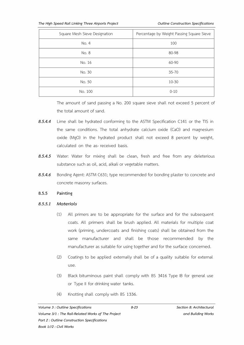
The High Speed Rail Linking Three Airports Project Outline Construction Specifications
Volume 3 : Outline Specifications 8-23 Section 8: Architectural Volume 3/1 : The Rail-Related Works of The Project and Building Works Part 2 : Outline Construction Specifications Book 1//2 : Civil Works
Square Mesh Sieve Designation Percentage by Weight Passing Square Sieve
No. 4 100
No. 8 80-98
No. 16 60-90
No. 30 35-70
No. 50 10-30
No. 100 0-10
The amount of sand passing a No. 200 square sieve shall not exceed 5 percent of the total amount of sand.
8.5.4.4 Lime shall be hydrated conforming to the ASTM Specification C141 or the TIS in the same conditions. The total anhydrate calcium oxide (CaO) and magnesium oxide (MgO) in the hydrated product shall not exceed 8 percent by weight, calculated on the as- received basis.
8.5.4.5 Water: Water for mixing shall be clean, fresh and free from any deleterious substance such as oil, acid, alkali or vegetable matters.
8.5.4.6 Bonding Agent: ASTM C631; type recommended for bonding plaster to concrete and concrete masonry surfaces.
8.5.5 Painting
8.5.5.1 Materials
(1) All primers are to be appropriate for the surface and for the subsequent coats. All primers shall be brush applied. All materials for multiple coat work (priming, undercoats and finishing coats) shall be obtained from the same manufacturer and shall be those recommended by the manufacturer as suitable for using together and for the surface concerned.
(2) Coatings to be applied externally shall be of a quality suitable for external use.
(3) Black bituminous paint shall comply with BS 3416 Type IB for general use or Type II for drinking water tanks.
(4) Knotting shall comply with BS 1336.
The High Speed Rail Linking Three Airports Project Outline Construction Specifications
Volume 3 : Outline Specifications 8-24 Section 8: Architectural Volume 3/1 : The Rail-Related Works of The Project and Building Works Part 2 : Outline Construction Specifications Book 1//2 : Civil Works
(5) Primers shall be of a type recommended by the manufacturer for the type of surface to which they are applied.
(6) Varnishes shall be clear and transparent.
(7) All materials shall be delivered to the Site in their original unbroken containers or packages bearing the manufacturer's names and labels. Mixing of all paints shall be done on site when required. Colours shall be non-fading and as selected by the SRT.
(8) Stopping materials for:-
Concrete, plastering, brickwork or wood particle and cement based boards shall be of similar material to the background and finished with a similar texture;
8.5.5.2 Samples
The Private Party is to provide samples of each type of paint in sealed containers to the Engineer’s Representative for his approval prior to bulk delivery of the paints and start of the work. During the execution of the Works, the Private Party shall provide the Engineer’s Representative with such further samples as he may request.
8.5.5.3 Preparation of Surfaces
(1) All metal fittings, fastening and ironmongery shall be removed prior to commencement of preparatory work and replaced after final finishing coat has been applied.
(2) All surfaces shall be inspected prior to commencement of works to make certain all defective workmanship has been remedied and material replaced.
(3) All surfaces shall be allowed to dry thoroughly before decorating. The Private Party shall brush down all surfaces immediately before decorating to remove dust, dirt and loose material.
(4) Cement render surface shall be scraped and wire brushed and any defective joints made good with cement mortar. Holes and uneven surfaces shall be filled and finished flush with surrounding surfaces. All surfaces shall be clean and dry. Plaster and concrete surfaces are to be cleaned of all dirt and grease and any cracks or holes are to be pointed up flush or cut out and replastered.

The High Speed Rail Linking Three Airports Project Outline Construction Specifications
Volume 3 : Outline Specifications 8-25 Section 8: Architectural Volume 3/1 : The Rail-Related Works of The Project and Building Works Part 2 : Outline Construction Specifications Book 1//2 : Civil Works
(5) Metal surfaces shall be scraped and brushed to remove all rust and scale and all surfaces shall be clean and free from dust, dirt and grease. Priming coats that have deteriorated shall be touched up to the Engineer’s Representative's satisfaction.
(6) Minor imperfections shall be filled with the same filler used for jointing. The Private Party shall repair any damage to the surface in accordance with the manufacturer's recommendations.
8.5.5.4 Workmanship Generally
(1) No work shall be done when plastering is in progress or is drying. Paint shall not be applied over wet or damp surfaces nor shall succeeding coats be applied until the previous coat is thoroughly dry.
(2) An ample supply of clean dust sheets to protect the work is to be available during decorating works.
(3) Suitable moveable receptacles shall be provided for liquid waste which shall on no account be thrown down any drain, sink, lavatory etc.
(4) No exterior or exposed decorating work shall be carried out under adverse weather conditions such as extremes of temperature, rain and mist or when the surfaces are damp.
(5) Paints shall be thoroughly stirred to attain an even consistency before use unless otherwise recommended by the manufacturer.
(6) Priming coats shall be applied by brush and worked into surfaces, joints, angles and end grain. Subsequent coats may be applied by brush, roller or spray.
(7) Backs of frames and linings and bottoms of doors shall be primed before fixing.
(8) The Private Party shall prime rebates and beads before glazing, and prime and paint after glazing and extend coating on to glass up to sight line.
(9) Each coat of paint shall be thoroughly dry, faced up, rubbed down with abrasive paper and cleaned off before application of subsequent coats.
The High Speed Rail Linking Three Airports Project Outline Construction Specifications
Volume 3 : Outline Specifications 8-26 Section 8: Architectural Volume 3/1 : The Rail-Related Works of The Project and Building Works Part 2 : Outline Construction Specifications Book 1//2 : Civil Works
(10) Each undercoat shall be of a different tint.
(11) Paint is to be evenly spread and thoroughly brushed.
8.5.5.5 Protection
The Private Party shall take all precautions to protect Decorations and shall replace if damage or deface and shall hand over all areas on completion in a clean condition. Replacement of damaged or defaced work may be extended at the Engineer’s Representative’s discretion to include the whole of the room or affected area.
8.5.5.6 Textured Acrylic Sprayed Paint
(1) Textured acrylic sprayed painting shall be as approved and of colours and texture to be selected by the SRT.
(2) The textured acrylic sprayed painting shall be applied to a cement and sand plastered base and used in accordance with the manufacturer's instructions.
8.5.5.7 Solvent Type Acrylic Coating
(1) Solvent type acrylic coating shall be as approved and of colours and texture to be selected by the SRT.
(2) The acrylic coating shall be applied in accordance with the manufacturer's instructions.
(3) The Private Party shall provide and apply acrylic coating on fair faced surfaces of concrete as required. All surfaces to be coated shall be dry, clean and free from dirt, dust or loose particles. Cracks, imperfect joints and other defects shall be stopped, filled or made good in accordance with proper structural procedures before the coatings are applied.
8.5.5.8 Epoxy Paint
(1) Epoxy paint shall be applied on both floor and wall where required in the finish schedule.
Epoxy paint shall be applied on doors, access panels and inspection panels, in the factory prior to installation of units.

The High Speed Rail Linking Three Airports Project Outline Construction Specifications
Volume 3 : Outline Specifications 8-27 Section 8: Architectural Volume 3/1 : The Rail-Related Works of The Project and Building Works Part 2 : Outline Construction Specifications Book 1//2 : Civil Works
(2) Epoxy paint on floor
Epoxy on floor shall be 2 coats dust-proofing epoxy resin sealer.
Epoxy paint system on floor:-
Primer coat: 1 x 50 microns (dry film thickness) 2 pack transparent. Polyamide cured epoxy varnish.
Top Coat: 2 x 120 microns (dry film thickness) high build, 2 pack, polyamide cured epoxy coating based on epoxy resin with high molecular
Application: To manufacturer’s recommendation
Surface preparation: The substrate must be clean, dry and undamaged.
Conditions during: Each coat should not be exposed to water, chemicals or application mechanical stress until fully cured.
Intercoating: Best intercoat adhesion occurs when the Subsequent, proceeding coat is fully cured.
Storage and Packing: To manufacturer's recommendation.
Health and Safety: The precautionary notices as displayed on the container
Fire Performance: Fire test comply to BS 476 part 6,7
Coefficient of friction (COF): 0.40
(3) Epoxy paint on wall :
Epoxy paint shall also be applied on R.C. wall or rendered blockwork wall. Epoxy paint system on Wall:-
Primer coat: 1 x 50 microns (dry film thickness), 2 pack transparent polyamide Cured epoxy varnish.

The High Speed Rail Linking Three Airports Project Outline Construction Specifications
Volume 3 : Outline Specifications 8-28 Section 8: Architectural Volume 3/1 : The Rail-Related Works of The Project and Building Works Part 2 : Outline Construction Specifications Book 1//2 : Civil Works
Top coat: 1 x 125 microns (dry film thickness) high build, 2 pack polyamide. Cured epoxy coating based on epoxy resin with high molecular weight.
Application: To manufacturer's recommendation
Surface preparation: The substrate must be clean, dry and undamaged.
Conditions during application: Each coat should not be exposed to water, chemicals or mechanical stress until fully cured.
Intercoating: Best intercoat adhesion occurs when the subsequent coat is applied before the proceeding coat is fully cured. After this time roughen the surface.
Storage and Packing: To manufacturer's recommendation.
Health and Safety: The precautionary notices as displayed on the container
Fire Performance: Fire test comply to BS 476 part 6,7
(4) Epoxy paint for steel doors, access panels and inspection panels·
Primer coat: 1 x 100 microns dry film thickness (dft.), 2 packs Zinc phosphate pigmented epoxy.
Under coat: 1 x 150 microns (dft), 2 packs surface tolerant, high solids epoxy based coating.
Top coat: 1 x 100 microns (dft), high build, a pack polymide epoxy.
Application: Airless spray, air spray roller and brush for small or Touch-up area.
Surface Preparation: Oil and grease removal. The substrate must be clean dry and free from contaminant.
The High Speed Rail Linking Three Airports Project Outline Construction Specifications
Volume 3 : Outline Specifications 8-29 Section 8: Architectural Volume 3/1 : The Rail-Related Works of The Project and Building Works Part 2 : Outline Construction Specifications Book 1//2 : Civil Works
Condition during application: Each coat should not be exposed to water, chemicals or mechanical application stress until fully cured
Intercoating: Best intercoat adhesion occures when the subsequent coat is applied before the proceeding coat is fully cured. After this time roughen the surface.
Storage and Packing: To manufacturer recommendation.
Health and Safety: The precautionary notices as displayed on the container.
Touch-up painting: 1 x 150 microns (dft), 2 packs surface tolerant, high solids epoxy based coating.
1 x 100 microns (dft), high build, 2 packs polymide epoxy.
Fire Performance: Fire test comply to BS 476 part 6, 7.
8.5.5.9 Emulsion paint
Emulsion paint shall be applied on soffit in staff operation rooms and plant rooms as shown in finishes schedules.
(1) Emulsion paint system:-
Primer coat: 1 x 35 microns (dry film thickness) acrylic emulsion primer or sealer.
Top coat : 2 x 35 microns (dry film thickness) plastic emulsion paint based on a 100% pure acrylic binder.
Application: To manufacturer's recommendation.
Surface preparation: The substrate must be clean, dry and undamaged.
Storage and Packing: To manufacturer's recommendation.

The High Speed Rail Linking Three Airports Project Outline Construction Specifications
Volume 3 : Outline Specifications 8-30 Section 8: Architectural Volume 3/1 : The Rail-Related Works of The Project and Building Works Part 2 : Outline Construction Specifications Book 1//2 : Civil Works
Health and Safety: The precautionary notices are displayed on the container.
Fire Performance: Fire test comply to BS 476 part 6, 7.
8.5.5.10 Polyurethane Paint
Polyurethane shall be applied to the Entrance Steel Structure.
(1) Polyurethane paint system : -
Primer coat 1 x 100 microns (dry film thickness) 2 packs zinc
phosphate pigmented epoxy resin.
2nd coat : 1 x 250 microns (dry film thickness), 2 packs surface tolerant high solids epoxy based coating.
Top coat: 1 x 50 microns (dry film thickness), 2 packs polyurethane. Excellent gloss and colour retention for aggressive atmospheric exposure.
Surface Preparation: Blasting to Sa 2.5 according to ISO 8501-1
Condition during: Each coat should not be exposed to water, chemicals or application mechanical stress until fully cured.
lntercoating: Best intercoat adhesion occurs when the subsequent coat is applied before the proceeding is fully cured. After this time roughen the surface.
Storage and Packing : To manufacturer's recommendation.
Health and Safety : The precautionary notices as displayed on the container.
Fire Performance : Fire test comply to BS 476 part 6, 7.
The High Speed Rail Linking Three Airports Project Outline Construction Specifications
Volume 3 : Outline Specifications 8-31 Section 8: Architectural Volume 3/1 : The Rail-Related Works of The Project and Building Works Part 2 : Outline Construction Specifications Book 1//2 : Civil Works
8.6 CEILING
8.6.1 Aluminium Ceiling
8.6.1.1 The Private Party shall provide shop drawings for the Engineer’s Representative's approval showing laying patterns and details.
8.6.1.2 Samples for verification purposes of each type of exposed finish required, prepared on samples of size indicated below and of same thickness and material indicated for final unit of the Works. Where finishes involve colour and texture variations, include sample sets showing full range of variations expected.
(1) Samples of finishes for selection by the Engineer’s Representative.
(2) 1.2m x 1.2m section of ceiling, each type, including each component with specified finish.
(3) Metal grid with specified finish, 300 mm length.
(4) Suspension system members, 300 mm. length.
8.6.1.3 The Works are subject to applicable portions of the following standards:
(1) AA "Finishes Designation System”, Aluminum Association.
(2) ASTM A591 "Specification for Steel Sheet, Electrolytic Zinc-Coated, for Light Coating Mass Applications", American Society for Testing and Materials.
(3) ASTM B209M "Specification for Aluminum and Aluminum-Alloy Sheet and Plate", American Society for Testing and Materials.
(4) ASTM B221M “Specification for Aluminum-Alloy Extruded Bars, Road, Wire, Shapes, and Tubes”, American Society for Testing and Materials.
(5) ASTM C423 “Test Method for Sound Absorption and Sound Absorbing Coefficients by the Reverberation Room Method’, American Society for Testing and Materials.
(6) ASTM C635 “Specification for Metal suspension Systems for Acoustic Tile and Lay-In Panel Ceilings”, American Society for Testing and Materials
(7) ASTM C636 “Practice for Installation of Metal Ceiling Suspension System for Acoustic Tile and Lay-In Panels”, American Society for Testing and Materials

The High Speed Rail Linking Three Airports Project Outline Construction Specifications
Volume 3 : Outline Specifications 8-32 Section 8: Architectural Volume 3/1 : The Rail-Related Works of The Project and Building Works Part 2 : Outline Construction Specifications Book 1//2 : Civil Works
(8) ASTM E488 "Test Method for Strength of anchors in Concrete and Masonry Elements”, American Society for Testing and Materials.
(9) ASTM E580 "Practice for Application of Ceiling Suspension Systems for Acoustical tile and Panels in Areas Requiring Seismic Restraint", American Society for Testing and Materials.
(10) ASTM D1730-67 "Standard Practice for Preparation of Aluminum and Aluminum-alloy Surfaces for Painting
8.6.1.4 Perforated Aluminum Plank Tile Ceiling with Acoustic- Clip-in System
(1) The aluminum panels are pressed or bent from aluminum alloy AA3105 - 1.0 mm. thick, size 600 x 600 mm., 600 x 1200 mm. The aluminum panel is at least 60 microns Electrostatic Powder Coated.
(2) Perforation pattern on the aluminum panels
Hole diameter: 2.6mm.
Open Area: At least 17%
(3) The perforated panels are bonded with black acoustic fleece to achieve the NRC=0.8 in accordance with ASTM C423-90A.
8.6.1.5 Perforated Aluminum Linear Tile Ceiling with acoustic- Clip-in System
(1) The aluminum panels are pressed or bent from aluminum alloy AA3105 - 1.0 mm. thick, size 600 x 600mm.,600 x 1200 mm The aluminum panel is at least 60 microns Electrostatic Powder Coated.
(2) Perforation pattern on the aluminum panels
Hole diameter : 2.6mm.
Open Area: At least 17%
(3) The perforated panels are bonded with black acoustic fleece to achieve the NRC=0.8 in accordance with ASTM C423-90A.
8.6.1.6 Aluminum Screen Ceiling with Acoustic- Clip-in System
The aluminum Liner panels are pressed or bent from aluminum alloy AA3105 0.55 mm. thick, size 100 mm The aluminum panel is at least 60 microns Electrostatic Powder Coated.
The High Speed Rail Linking Three Airports Project Outline Construction Specifications
Volume 3 : Outline Specifications 8-33 Section 8: Architectural Volume 3/1 : The Rail-Related Works of The Project and Building Works Part 2 : Outline Construction Specifications Book 1//2 : Civil Works
8.6.1.7 Suspension systems, General
(1) Standard for metal suspension systems: Provide manufacturer's standard for indicated types, structural classifications, and finishes that comply with applicable ASTM C635 requirements.
(2) Hangers and ties: hanger is to be “U” profile channel to withstand the uplift load, made from hot dip galvanized steel with min. 0.5 mm thick. The ceiling level is to be adjusted by adjustable spring.
(3) The ceiling suspension system is the interlocking and knock-down system by screw and rivet, no welding.
8.6.1.8 Fire Propagation and Surface Spread of Flame
Ceiling panels is to be tested in accordance to BS476 part 6 and part 7 giving a result of class "0" in accordance with building regulation.
8.6.2 Aluminium Composite Cladding
8.6.2.1 The Private Party shall provide shop drawings for the Engineer’s Representative's approval showing laying patterns and details of cut panel.
8.6.2.2 The aluminum composite material shall be composing of white fire resistance core sandwiched between two skins of 0.5 mm. thick aluminum sheets. Panel thickness shall be not less than 4 mm. or as indicated on the Drawings.
8.6.2.3 The surface is finished with fluorocarbon coating or other equivalent approval on the topside and service coating on the reverse side.
8.6.2.4 Two kinds of coating system for fluorocarbon coating (70% resin) shall be selected by the Engineer’s Representative for achieving of the architectural design intent.
(1) "Solid Color" is two-coat two-bake system. The total dry film thickness of the top side shall be 25 μ minimum consisting of a conversion coating, an inhibitive primer and fluorocarbon coating.
(2) "Metallic Color" is two-coat two-bake or tree-coat three-bake system. That thickness shall be 35 μ minimum consisting of a conversion coating, an inhibitive primer, metallic coating and clear coating if it is three coats.

The High Speed Rail Linking Three Airports Project Outline Construction Specifications
Volume 3 : Outline Specifications 8-34 Section 8: Architectural Volume 3/1 : The Rail-Related Works of The Project and Building Works Part 2 : Outline Construction Specifications Book 1//2 : Civil Works
8.6.2.5 The finished surface shall be protected with a self-adhesive peel off foil with layers of white and black.
8.6.2.6 Composition
(1) Skin material- 0.5 mm thick aluminum sheet. (3105- H14)
(2) Core material white fire resistance core consisting of AI (OH)3 or Mg(OH)2 which achieve the B1 fire test.
8.6.2.7 References
ECCA (European Coil Coating Association)
(1) DIN EN 13523-3 "Color Difference"
(2) DIN EN 13523-2 “Specular Gloss”
(3) DIN EN 13523-14 “Chalking”
(4) DIN EN 13523-6 "Adhesion after indentation”
(5) DIN EN 13523-4 "Pencil hardness"
(6) DIN EN 13523-12 "Resistance to scratch"
(7) DIN EN 13523-25 "Resistance to humidity"
(8) DIN EN 13523-5 “Resistance to impact deformation”
(9) DIN EN 13523-1 “Coating thickness”
(10) DIN EN 13523-7 "Resistance to cracking on bending"
(11) DIN EN 13523-8 "Resistance to salt spray"
AAMA (American Architectural Manufacturers Association).
(1) ASTM D 2244-93 "Color retention"
(2) ASTM D 523-89 "Gloss retention"
(3) ASTM D 4214-89 "Chalk resistance"
(4) ASTM D 3359-95a "Adhesion test"
(5) ASTM D 3363-92a "Pencil hardness"
(6) ASTM D 968-81 "Abrasive resistance"
The High Speed Rail Linking Three Airports Project Outline Construction Specifications
Volume 3 : Outline Specifications 8-35 Section 8: Architectural Volume 3/1 : The Rail-Related Works of The Project and Building Works Part 2 : Outline Construction Specifications Book 1//2 : Civil Works
(7) ASTM D2247-94 "Humidity resistance"
(8) ASTM D2794 “Impact resistance"
(9) ASTM B244 "Dry film thickness"
(10) ASTM B4145 "T-bend test"
(11) ASTM B117 "Resistance to salt spray”
Fire code test
(1) BS 476 Part 5 “Surface Spread of Flame Classification”
(2) BS 476 Part 6 “Fire Propagation”
(3) BS 476 Part 7 “Ignitability”
(4) DIN 4102 PART 1 “Reaction to Fire”
(5) ASTM E84 “Steiner Tunnel Test”
(6) ASTM E108 “Roof Covering”
(7) ASTM E119 "Fire Rating Test"
(8) UBC 26-9 “Intermediate Scale Multi - Story Apparatus"
(9) UL- 94 “Horizontal Burning Test"
(10) ISO-TR-9122-3 "Toxic Fume Evaluation”
(11) ANSI/ UL 263 “Standard for safety for fire tests of building Construction and materials”
8.6.3 Gypsum Board
8.6.3.1 The Private Party shall provide shop drawings for the Engineer’s Representative's approval showing laying patterns and details.
8.6.3.2. Gypsum plaster board ceilings shall be installed on concealed suspension system in areas where indicated on Drawings. They shall be in 9.0mm thick in convenient panel sizes fixed to aluminum or other approved metal suspension system in accordance with the manufacturer's instructions.
The High Speed Rail Linking Three Airports Project Outline Construction Specifications
Volume 3 : Outline Specifications 8-36 Section 8: Architectural Volume 3/1 : The Rail-Related Works of The Project and Building Works Part 2 : Outline Construction Specifications Book 1//2 : Civil Works
8.6.3.3 The panels shall be fixed butt jointed and taped over, grouted on at back of board and filled in with gypsum plaster to obtain a jointless and even surface. All screw heads shall be sunk into the ceiling boards and filled in with gypsum plaster. The gypsum plaster board shall be prepared to receive a skim coat of gypsum plaster minimum 3mm thick to be finished to smooth and even surface. The gypsum plaster board ceiling shall be finished with patent sealer and two coats of emulsion paint of approved colour.
8.6.3.4 The concealed suspension system for the gypsum plaster board ceiling shall generally consist of a channel grid system with main spines spaced at 600mm centres and furring channels at minimum 600mm centres and with suspension rods spaced at 600mm centres both ways.
8.6.3.5 Openings shall be provided for recessed light fixtures, air-conditioning diffusers, registers, grilles, columns, access panels, etc. including provision of additional framings, hangers and the like. Weight of fixtures shall be borne independently.
8.6.3.6 The Private Party shall submit full details on the type of ceiling systems proposed complete with fixing and suspension system details for the consent of the Engineer’s Representative.
8.6.4 Calcium Silicate Board
8.6.4.1 The Private Party shall provide shop drawing for the Engineer’s Representative’s approval showing laying patterns and details
8.6.4.2 References
(1) BS 476: Part 22 Fire test on building material and structure. Non combustible test for material.
(2) BS 476: Part 7 Fire test on building material and structure. Method of test to determine the classification of the structure spread of flame of product.
(3) BS 476: part 4 Fire test on building materials and structures. Non-combustibility test for materials.
8.6.4.3 The system shall be tested or assessed in accordance with BS 476: Part 22. The system shall meet the stability and integrity criteria for 120 minutes
The High Speed Rail Linking Three Airports Project Outline Construction Specifications
Volume 3 : Outline Specifications 8-37 Section 8: Architectural Volume 3/1 : The Rail-Related Works of The Project and Building Works Part 2 : Outline Construction Specifications Book 1//2 : Civil Works
8.6.4.4 Product Data detail of the following must be supplied
(1) Board Thickness
(2) Metal frame and support
(3) Material Specification
(4) Finishing specification
(5) Test report or assessment report according to BS 476: Part 24
(6) Detail drawing: Fastening, spacing, dimension, hanger and support
8.6.4.5 All ceiling shall be in 9.0mm thick in convenient panel sizes fixed to aluminum or other approved metal suspension system in accordance with the manufacturer's instructions.
8.6.4.6 All ceiling systems as before specified shall be in aluminum or other approved metal suspension system for both exposed and concealed ceilings, and shall comply with BS476, BS8290 or ASTM C636.
8.6.4.7 The suspension system shall consist of the appropriate T-bars to form the panel sizes and with minimum 38mm deep main carrying channels or spine spaced at maximum 600mm centres. The whole suspension system shall be hung from the concrete soffit by means of minimum 5mm diameter galvanised rod hangers fixed to cast in support anchors.
8.6.4.8 The 5mm diameter galvanised rod hangers shall be in two parts. The top portion hooked on to an angle bracket, one end holed to receive the rod hanger and other end in the concrete soffit. The lower portion of the hanger is fixed to the main carrying channel or spine of the grid system at 600mm centres both ways by means of spring clips or hooking around the channel and fixed to the upper portion with a flat spring clip to permit adjustments in the leveling of the ceiling boards.
8.6.5 Composite Panel of Fiber Reinforced Cement
8.6.5.1 The Private Party shall provide shop drawings for the Engineer’s Representative’s approval showing laying patterns and details.

The High Speed Rail Linking Three Airports Project Outline Construction Specifications
Volume 3 : Outline Specifications 8-38 Section 8: Architectural Volume 3/1 : The Rail-Related Works of The Project and Building Works Part 2 : Outline Construction Specifications Book 1//2 : Civil Works
8.6.5.2 References
(1) BS 476: Part 22 Fire test on building material and structure. Non combustible test for material
(2) BS 476: Part 7 Fire test on building material and structure. Method of test to determination the classification of the surface spread of flame of product.
(3) BS 476: Part 24 Fire test on building material and structure. Method for determining ventilation duct.
(4) BS 5669: Part 1 1989: Clause 21
8.6.5.3 The System shall be tested or assessed in accordance with BS 476 : Part 22. The system shall meet the stability and integrity criteria for 180 minutes.
8.6.5.4 Product Data detail of the following must be supplied
(1) Board Thickness
(2) Metal frame and support
(3) Material Specification
(4) Finishing Specification
(5) Test report or assessment report according to BS 476: Part 24
(6) Detail drawing: Fastening, spacing, dimension, hanger and support
8.6.5.5 Composite Panel of fiber reinforced cement
- Nominal weight: 16.8 kg/m2
- Thickness: 6 mm
- Flexural Strength (BS EN 12467: 2000) 109 Mps
- Flexural Strength (BS EN 12467: 2000) 109 Mps
- Fire performance to BS 476: Part 4: 1970: Non-combustible
- Surface spread of flame (BS479: Part 7: 1971): Class 1
- Radiant heat reduction through panel 2948.0-802.0 Btu/ft h ºF
The High Speed Rail Linking Three Airports Project Outline Construction Specifications
Volume 3 : Outline Specifications 8-39 Section 8: Architectural Volume 3/1 : The Rail-Related Works of The Project and Building Works Part 2 : Outline Construction Specifications Book 1//2 : Civil Works
8.6.5.6 Supporting Structure
Structure element that the ductwork system is supported from e.g. a beam, floor, purlin of roof structure.
8.6.5.7 Hanger Support
The supporting hanger, support and their fixing should be capable of bearing the load of the complete ceiling system including any applied insulation material or other service suspended from it. Chemical anchor are not generally suitable.
8.6.6 Steel Security Grating
8.6.6.1 The Private Party shall provide shop drawings for the Engineer’s Representative’s approval showing laying patterns and details.
8.6.6.2 Conform to Code, AISC Code of Standard Practice for Steel Buildings and Bridges; AISC Specification for the Design, Fabrication and Erection of Structural Steel for Building; AISC Steel Construction Manual; and AWS D1.1 Structural Welding Code.
8.6.6.3 Furnish materials conforming to the following:
Steel shapes: ASTM A36 or JIS G31010 Class SS41
Steel Tubing: ASTM A36 ASTM A500, ASTM A501, or JIS G3444 Class TK41
Steel Pipe: ASTM A53 Schedule 40 for general use, ASTM A53 Grade B (or JIS G3466 Class STK244) for structural use, unless otherwise shown or specified.
8.6.6.4 Gratings: steel gratings and frames, all grating edges banded full height. Grating shall be minimum 50 mm by 5 mm bearing bars spaced 30 cm O.C. cross bar size 6 mm diameter spaced 10 cm.
8.7 ROOFING
8.7.1 Aluminum Sheet Roofing
8.7.1.1 The Private Party shall provide shop drawings for the Engineer’s Representative's approval showing laying patterns and details.
The High Speed Rail Linking Three Airports Project Outline Construction Specifications
Volume 3 : Outline Specifications 8-40 Section 8: Architectural Volume 3/1 : The Rail-Related Works of The Project and Building Works Part 2 : Outline Construction Specifications Book 1//2 : Civil Works
8.7.1.2 Standing Seam Aluminium Roofing shall be supplied by the manufacturer to suit the building as shown on the Drawings and shall be installed under the supervision of the manufacturer and in accordance with the recommendations.
8.7.1.3 Standing seam aluminium roofing shall be corrugated color coated metal sheet as specified in this section. Plain and folded metal sheet shall be used, for louvers and flashings, whichever is applicable or as indicated on the Drawings.
8.7.1.4 Materials: Sheet shall be a closed cell system.
8.7.1.5 Description
(1) The metal sheet shall be manufactured from aluminum alloy AlMn1Mg1 as specified in DIN 1725 (comparable AA3xxx), the surface of the material shall be finish coating with PVDF (20-25 microns thick) coating as specified in the drawings.
(2) The total metal sheet thickness shall not be less than 0.9 mm.
(3) The standing seam aluminium roofing shall be supplied in single lengths with no laps and minimum cover- width of 350 mm. and a standing seam height shall not less than 50 mm. and approved manufacture standard. Sheets are to be laid to meet the requirements of the building geometry.
(4) The aluminum alloy sheets shall be able to curve without crimping (smooth curve) with minimum radius of 4.5 m.
8.7.1.6 Finish Coating
(1) All aluminum alloy or aluminium-zinc alloy coated metal sheets shall have a conversion and a primer (not less than 5 microns thick) coating before receiving the finish coating.
(2) For roofing, siding and louver sheets both side shall receive aluminium and zinc alloy coating of not less than ·150 g/m².
(3) The finish coat for both sides shall be a part of the continuous fabrication process of the roofing & siding process.
(4) Finish coat neither for topside nor back side may under no condition be put as a field coating
The High Speed Rail Linking Three Airports Project Outline Construction Specifications
Volume 3 : Outline Specifications 8-41 Section 8: Architectural Volume 3/1 : The Rail-Related Works of The Project and Building Works Part 2 : Outline Construction Specifications Book 1//2 : Civil Works
8.7.1.7 Durability
Selected material shall be durable and satisfy the requirements of the General Specification for the design life of the Works. The Roof System shall be awarded certificate by the British Board of Agreement or ASTM with regards to the general use of aluminium profiled roof sheets, with a minimum recommended service life of 40 years in rural and suburban environments and a minimum 25 years in industrial or marine environments.
8.7.1.8 Insulation
Thermal insulation material will be 100 mm. thick rockwool with a minimum density 60kg/m³ thermal conductivity= 0.034 w/mk at 20°c.
8.7.2 Metal Sheet Roofing
8.7.2.1 The Private Party shall provide shop drawings for the Engineer’s Representative's approval showing laying patterns and details.
8.7.2.2 References.
(1) ASTM A792a, "Specification for Steel Sheet, 55% Aluminum-Zinc Alloy- Coated by the Hot-Dip Process," American Society for Testing and Materials, 1997.
(2) ASTM A653, "Specification for Steel Sheet, Zinc-Coated (Galvanized) or Zinc-Iron Alloy-Coated (Galvannealed) by the Hot-Dip Process," American Society for Testing and Materials, 1998.
(3) ASTM E1514, "Specification for Structural Standing Seam Steel Roof Panel Systems," American Society for Testing and Materials, 1993.
(4) ASTM E1592, "Test Method for Structural Performance of Sheet Metal Roof and Siding Systems by Uniform Static Air Pressure Difference," American Society for Testing and Materials, 1995.
(5) ASTM E1646, "Test Method for Water Penetration of Exterior Metal Roof Panel Systems by Uniform Static Air Pressure Difference," American Society for Testing and Materials, 1995.
(6) ASTM E1680, “Test Method for Rate of Air Leakage through Exterior Metal Roof Panel Systems." American Society for Testing and Materials, 1995.

The High Speed Rail Linking Three Airports Project Outline Construction Specifications
Volume 3 : Outline Specifications 8-42 Section 8: Architectural Volume 3/1 : The Rail-Related Works of The Project and Building Works Part 2 : Outline Construction Specifications Book 1//2 : Civil Works
(7) UL 580, "Tests for Uplift Resistance of Roof Assemblies", Underwriters Laboratories, Inc., 1994.
(8) TIS 2131 2545 Pre painted hot-dip zinc-coated steel : coils and sheets
(9) JID G- 3312
8.7.2.3 Description
(1) The metal sheet shall be high tensile metal sheet AZ (150) and pre-finished with zinc aluminum alloy and Polyester (20-25 microns thick) coating.
(2) The Total Coated Thickness shall not be less than 0.53 mm.
8.7.2.4 Finish Coating
(1) All aluminum-zinc alloy coated metal sheets shall have a conversion and a primer (not less than 5 microns thick) coating before receiving the finish coating.
(2) For roofing, sliding and louver sheets both side shall receive aluminum and zinc alloy coating of not less than 150 g/m².
(3) The finish coat for both sides shall be part of the continuous fabrication process of the roofing & siding process.
(4) Finish coat neither for topside nor back side may under no condition be put as a field coating.
8.7.2.5 Durability
Selected materials shall be durable and satisfy the requirements of the General Specification for the design life of the Works. The Roof System shall be awarded certificate by the British Board of Agreements or Australian Standard with regards to the general use of profiled roof sheets, with a recommended service life of 30 years in rural and suburban environments and a minimum 20 years in industrial or marine environments.
8.7.2.6 Metal sheet accessories including ridge flashing, gable covering, cornice covering, cove covering, closures and other sheet accessories shall have same characteristics as the roofing and side described above.

The High Speed Rail Linking Three Airports Project Outline Construction Specifications
Volume 3 : Outline Specifications 8-43 Section 8: Architectural Volume 3/1 : The Rail-Related Works of The Project and Building Works Part 2 : Outline Construction Specifications Book 1//2 : Civil Works
8.7.3 Flashing and Trim
8.7.3.1 The Private Party shall provide shop drawings for the Engineer’s Representative's approval showing laying patterns and details.
8.7.3.2 This Specification includes
(1) Ridge flashing
(2) Gable Covering
(3) Corner Covering
(4) Parapet Flashing
(5) Curve Hip Capping
(6) Flashing Tape
(7) Supporting material to complete work
8.7.3.3 References
The publication listed below form a part of this section to the extent referenced:
American Welding Society (AWS)
AWS D1.1/D1 1M (2004) Structural Welding Code-Steel
AWS D1.2 (2003) Structural Welding Code Aluminum
ASTM International (ASTM)
ASTM A 240/A 240M (2004) Standard Specification for Stainless and Heat-Resisting Chromium– Nickel Steel Plate, Sheet, and Strip for Pressure Vessels
ASTM A 480/A 480M (2004) Standard Specification for General Requirements for Flat-Rolled Stainless and Heat-Resisting Steel Plate, Sheet and Strip
ASTM A 635/A 635M (2003) Standard Specification for Steel Sheet, Zinc – Coated (Galvanized) or Zinc – Iron Alloy – Coated (Galvannealed) by the Hot-Dip Process

The High Speed Rail Linking Three Airports Project Outline Construction Specifications
Volume 3 : Outline Specifications 8-44 Section 8: Architectural Volume 3/1 : The Rail-Related Works of The Project and Building Works Part 2 : Outline Construction Specifications Book 1//2 : Civil Works
ASTM A 924/A 924M (1999) Standard Specification for General Requirements for Steel Sheet, Metallic-Coated by the Hot-Dip Process
ASTM B 209/B 209M (2004) Standard Specification for Aluminum and Aluminum-Alloy Sheet and Plate
ASTMB B224 (1998) Standard Classification of Coppers
ASTM B32 (2003) Standard Specification for Solder Metal
ASTM B 370 (2003) Standard Specification for Copper Sheet and Strip for Building Construction
ASTM B920 (2002) Standard Specification for Elastomeric Joint Sealants
ASTM B 4586 (2000) Standard Specification for Asphalt Roof Cement, Asbestos Free
Sheet Metal & Air Conditioning Contractors’ National Association (SMACNA)
SMACNA 1793 (2003) Architectural Sheet Metal Guideline
8.7.3.4 Sheet Metal Materials
(1) Aluminum
Sheet and strip aluminum shall conform to ASTM B 209/B 209M, embossed finish, clad on side and specified temper. Minimum tensile strength shall be 160 Megapascal.
(2) Galvanized Steel
Galvanized steel sheet shall conform to ASTM A 924/A 653/A 653M and ASTM A 653/A 653M, regular coating, designation Z90.
(3) Corrosion-Resistance Steel
Corrosion-resistance steel shall be chromium-nickle steel conforming to (ASTM A 167) (ASTM A 240/A 240M), and ,ASTM A 480/A 480M, No. 2D finish, annealed temper as required for the end use.
The High Speed Rail Linking Three Airports Project Outline Construction Specifications
Volume 3 : Outline Specifications 8-45 Section 8: Architectural Volume 3/1 : The Rail-Related Works of The Project and Building Works Part 2 : Outline Construction Specifications Book 1//2 : Civil Works
(4) Copper
Copper shall be standard (electrolytic tough-pitch copper, Type ETP (fire-refined tough- pitch copper, Type FRTP) as classified in ASTM B 224 and conforming to ASTM B 370, cold-rolled temper.
8.7.3.5 Minimum Dimensions and Thicknesses
Materials shall be in accordance with ASMCNA 1793.
8.7.4 Glazed Skylight
8.7.4.1 The Private Party shall provide shop drawings for the Engineer’s Representative’s approval showing laying patterns and details.
8.7.4.2 References
(1) ASTM C162- Standard Terminology of Glass and Glass Products
(2) ASTM C1036- Standard Specification for Flat Glass.
(3) ASTM C1048 Standard Specification for Heat-Treated Flat Glass-- Kind HS, Kind FT Coated and Uncoated Glass.
(4) ASTM C1376- Standard Specification for Pyrolytic and Vacuum Deposition Coatings on Glass.
(5) ASTM C1300 - Standard Practice for Determining the Minimum Thickness and Type of Glass Required to Resistance a Specified Load
(6) ASTM C 1193 Standard Guide for Use of Joint Sealants.
8.7.2.3 Materials
(1) Heat-Strengthened Float Glass
Glass Type: Heat-treated glass Glass Tint: Clear
Nominal Thickness: 6 mm + 0.76mm PVB + 6 mm
Coating Orientation: (N/A, Surface #1 or 2) Performance Characteristics (Center of Glass)
(2) Heat-Strengthened float glass shall comply with ASTM C1048, Type I, Class 1 (clear), Class 2 (tinted), Quality Q3, Kind HS.

The High Speed Rail Linking Three Airports Project Outline Construction Specifications
Volume 3 : Outline Specifications 8-46 Section 8: Architectural Volume 3/1 : The Rail-Related Works of The Project and Building Works Part 2 : Outline Construction Specifications Book 1//2 : Civil Works
(3) Glass heat-treated by horizontal (roller hearth) process with inherent roller wave distortion parallel to the bottom edge of the glass as installed when specified.
8.7.5 Roof Gutter
8.7.5.1 The Private Party shall provide shop drawing for the Engineer’s Representative’s approval showing laying patterns and details.
8.7.5.2 References
American Welding Society (AWS)
AWS D1.1/D1.1M (2004) Structural Welding Code-Steel
AWS D1.2 (2003) Structural Welding Code Aluminium
American Society for Testing and Materials (ASTM)
A167-96 Specification for Stainless and Heat-Resisting Chromium-Nickel Steel Plate Sheet and Strip
A240/96a Specification for Heat-resisting Chromium and Chromium-nickel Stainless Steel Plate, Sheet and Strip for Pressure Vessels.
B32-96 Specification for Solder Metal
D4586-93 Specifications for Asphalt Roof Cement Asbestos-Free.
ASTM A 240/A 240M Standard Specification for Heat-Resisting Chromium Nickel Steel Plate, Sheet, and Strip for Pressure Vessels
ASTM A 480/A 480M Standard Specification for General Requirements for Flat- Rolled Stainless and Heat-Resisting Steel Plate, Sheet, and Strip
ASTM A 635/A 635M (Standard Specification for Steel Sheet, Zinc-Coated (Galvanized) or Zinc-Iron Alloy-Coated (Galvannealed) by the Hot- Dip Process
ASTM A 924/A 924M Standard Specification for General Requirements for Steel Sheet, Metallic-Coated by the Hot-Dip Process
ASTM B 209/B 2094M Standard Specification for Aluminum and Aluminum-Alloy Sheet and Plate
The High Speed Rail Linking Three Airports Project Outline Construction Specifications
Volume 3 : Outline Specifications 8-47 Section 8: Architectural Volume 3/1 : The Rail-Related Works of The Project and Building Works Part 2 : Outline Construction Specifications Book 1//2 : Civil Works
ASTM B 224-16 Standard Classification of Coppers
ASTM B 32-08(2014) Standard Specification for Solder Metal
ASTM B 370-12 Standard Specification for Copper Sheet and Strip for Building Construction
ASTM C 920 Standard Specification for Elastomeric Joint Sealants
ASTM D 4586 Standard Specification for Asphalt Roof Cement, Asbestos free
Sheet Metal & Air Conditioning Contractors' National Association (SMACNA)
SMACNA 1793 Architectural Sheet Metal Guideline
8.7.5.3 Samples·
(1) 150 mm. square samples of specified sheet materials to be exposed as finished surfaces.
(2) 150 mm long samples of factory fabricated products exposed as finished work. Provide complete with specified factory finish
8.7.5.4 Material: Stainless Steel Sheet
(1) Type 304 stainless steel, complying with ASTM A167.
(2) Flashing for Pipes, Conduits, and Round Equipment Supports: Type 304 stainless steel, 26 gage, 2B complying with ASTM A240/A.
(3) Solder: According to ASTM B32
(4) Fastening Devices: Fasteners shall be compatible with metal and roofing system. Use of powder activated fasteners is prohibited.
(a) For Attaching Sheet Metal to Wood to Wood with concealed Fastenings : Hot dip galvanized ring shank roofing nails not less than 1-1/4" long.
(b) For Attaching Sheet Metal to wood with Exposed Fastenings: No.10 x 1-1/4" pan head stainless steel sheet metal screws. Provide neoprene sealant washers and stainless steel washers under screw heads.

The High Speed Rail Linking Three Airports Project Outline Construction Specifications
Volume 3 : Outline Specifications 8-48 Section 8: Architectural Volume 3/1 : The Rail-Related Works of The Project and Building Works Part 2 : Outline Construction Specifications Book 1//2 : Civil Works
(c) For Attaching Sheet Metal to Metal Walkway Covers: No10 x 1/2" pan head stainless steel sheet metal screws. Provide neoprene sealant washers and stainless steel washers under screw heads.
(d) For Attaching Sheet Metal to Masonry or Concrete: No.10 x 1-1/4" pan head Tap-Con zinc plated concrete tapping screws. Provide neoprene sealant washers and stainless steel washers under screw heads.
(5) Roofing Cement: Plastic roofing cement complying with the requirements of ASTM D2822 or as appropriate and as recommended by roofing manufacturer.
(6) SBS Flashing Cement : Roofing cement according to ASTM D4586
(7) Splash Blocks: Approximately 2 foot x 1 foot 6 inches x 1-1/2" thick reinforced concrete slabs with recess formed in top to deflect water away.
Roof Drain Flashing : 16 ounce 30 inches by 30 inches copper flashing
8.8 TOILET AND ACCESSORIES
8.8.1 Toilet and Accessories
8.8.1.1 The Private Party shall provide shop drawings for the Engineer’s Representative's approval showing layout and all the details.
8.8.1.2 The Private Party shall take delivery of all sanitary fittings, check, sort, store and protect them. He shall prepare a schedule of sanitary fittings for the purposes of checking and installing the fittings to the consent of the Engineer’s Representative.
8.8.1.3 The Private Party shall assemble and fix only the sanitary fittings and accessories at the correct locations, including providing all necessary jointing and sealing compounds, additional screws and bolts, cutting, recesses and chases and making good, bedding wastes and traps in approved jointing compound.
8.8.1.4 The Private Party shall also protect the sanitary fittings before and after installation from damages by other tradesmen and also protect other finished works from damages while installing the sanitary compound.
The High Speed Rail Linking Three Airports Project Outline Construction Specifications
Volume 3 : Outline Specifications 8-49 Section 8: Architectural Volume 3/1 : The Rail-Related Works of The Project and Building Works Part 2 : Outline Construction Specifications Book 1//2 : Civil Works
8.8.1.5 Extent of Work required shall be indicated on the Drawings. Sanitary fittings shall generally comprise the following:
Sanitary fixtures and tap.
Toilet Accessories
8.8.1.6 Provide sanitary fitting support systems and related accessories that have been designed, produced, fabricated and installed without failure including scratched, flawed or chipped finishes, loose parts, dripping taps, or leaking seals and other defects in the Work.
8.8.1.7 Installer Qualifications: The installer shall have completed installations similar in material, design, and extent to that indicated for the Project that have resulted in construction with a record of successful in-service performance for a period of not less than five years immediately prior to this Contract.
8.8.1.8 Sanitary fitting products shall allow for adjustment during installation to obtain proper alignment and installation tolerances.
8.8.1.9 The sanitary fitting system shall be effectively electrically continuous and bonded to an earth terminal and any hinged, moveable or removable metallic parts shall be provided with a permanent connection to the earth terminal.
8.8.1.10 Disabled Grabrail
1. All grabrails shall for disabled toilet conform to the following standard :
BS 5810.
Thai Disabled Codes and Standard : Ministerial Regulation No.4 (B.E.2542) issued pursuant to Rehabilitation of the Handicapped Act, B.E.2534; Rehabilitation Committee's Regulation on Standards for Equipment or Facilities for Disablities B.E.2544
Ministerial Regulation on Provision of Building Facilities for Disabled Person and Senior Citizen, B.E.2548 and other relevant Thai standards for disabled person
2. All grabrails shall be 38.10 mm. outside dia. stainless steel 304 hairline finish.
The High Speed Rail Linking Three Airports Project Outline Construction Specifications
Volume 3 : Outline Specifications 8-50 Section 8: Architectural Volume 3/1 : The Rail-Related Works of The Project and Building Works Part 2 : Outline Construction Specifications Book 1//2 : Civil Works
8.8.2 Toilet Partition
8.8.2.1 The Private Party shall provide shop drawings for the Engineer’s Representative's approval showing layout and all the details.
8.8.2.2 Materials:
Toilet Cubicles wall shall be high pressure laminated panel. The standard cubicle shall be 900 x 1800 mm. 1750 mm. high (excluding 150 mm. support to panel). The intermediate panel or pilaster shall be 1750 mm. high. The door size shall be 600 mm. wide and 1650 mm. high.
8.8.2.3 Compartment
Generally, they shall comprise doors, panels and pilasters with drilled holes and anchorages as manufacturing method to receive partition-mounted hardware and all accessories.
Top channel shall be furnished with anchorage devices between compartments. Install compartments units rigid, plumb and level. Door shall be flush within pilasters. Side pilasters shall be sealed by brush vision seal. No vision gap allowable between doors.
8.8.2.4 Hardware:
Hardware shall be made of stainless steel, hairline finish and shall be as follows:
Adjustable Footing.
Lockset & Receiver
Hinges.
Cloth hook & Bumper.
Toilet Paper Roll Holder.
U-Profile (panel holder) and/or L-Profile (panel bracing).
Other hardware accessories.
Sample of all hardware shall be submitted for approval.
The High Speed Rail Linking Three Airports Project Outline Construction Specifications
Volume 3 : Outline Specifications 8-51 Section 8: Architectural Volume 3/1 : The Rail-Related Works of The Project and Building Works Part 2 : Outline Construction Specifications Book 1//2 : Civil Works
8.8.2.5 Mock-up:
A mock-up shall be submitted for approval. The mock-up shall comprise the toilet cubicles which shall show corner, intermediate junction and wall junction, also include door, door hardware & accessories and all compartment system.
8.9 STAIRS AND RAILING
8.9.1 Concrete finishes
8.9.1.1 The Private Party shall provide shop drawings for the Engineer’s Representative's approval showing laying patterns and details.
8.9.1.2 Granite Tiling for concrete staircase finish:
- 25 mm thickness Granite tiles waterjet finish for stair treads as specified on the Drawings.
- 20 mm thickness Granite tiles polished finish for stair treads as specified on the Drawings.
- Cramp & Pin fixing with galvanized steel expansion bolts with washers as specified on the approved shop drawings.
8.9.1.3 Tiling Adhesive:
- Composite material, Carborundum stops edge infills on stair tread as specified on the Drawings.
- Penetrating Sealer or Water Repellant Treatment
8.9.1.4 Floor Hardener with Carborundum for concrete staircase finish:
- Aluminum stair nosing
- Aluminum counter-sunk bolt/nut (M4)
- Aluminum or galvanized steel flat-bar (60x3 mm.)
- Galvanize steel expansion bolt (M6) and Washers
- Color mortar render
- Galvanized metal lath
- Corner bead for rendering

The High Speed Rail Linking Three Airports Project Outline Construction Specifications
Volume 3 : Outline Specifications 8-52 Section 8: Architectural Volume 3/1 : The Rail-Related Works of The Project and Building Works Part 2 : Outline Construction Specifications Book 1//2 : Civil Works
- Floor Hardener with Carborundum finish: Non-metallic floor hardener consists of natural aggregates blended with cement and resin mortars with abrasion resistance complying with ASTM C 779/C779M-12.
8.9.2 Metal structural stairs finishes
8.9.2.1 The Private Party shall provide shop drawings for the Engineer’s Representative's approval showing layout and all the details.
8.9.2.2 Furnish materials conforming to the following: Steel shapes: ASTM A36 or JIS G3101 Class SS400 Steel Tubing: ASTM A36, A500, or A501
Steel pipe: ASTM A120 standard weight for general use; ASTM A53 Grade B where used for structural purposes
Steel Sheet: ASTM A570, Grade A, or ASTM A611, Grade A Checker Steel plate: ASTM A36 or JIS G3101 Class SS400 Bolts and nuts: ASTM A307
Electrodes: AWS D1.1, E70XX Series as required for intended use
Shop primer:
Manufacturer’s or fabricator’s standard, fast-curing, lead-free, universal modified alkyd primer selected for good resistance to normal atmospheric corrosion, and for capability to provide a sound foundation for field-applied topcoats despite prolonged exposure complying with performance requirements of FS TT-P645.
Galvanizing repair paint: High zinc dust content paint with dry film containing not less than 94% zinc dust by weight, and complying with DOD-P-21035 or SSPC Paint 20
Bituminous paint: Cold-applied asphalt mastic complying with SSPC Paint 12, except containing no asbestos fibers.
Non-shrink grout: Bolt inserts:
Steel grating: Manufacture and pattern indicated, designed to support loads required by code for stair construction, minimum percentage opening as shown.
The High Speed Rail Linking Three Airports Project Outline Construction Specifications
Volume 3 : Outline Specifications 8-53 Section 8: Architectural Volume 3/1 : The Rail-Related Works of The Project and Building Works Part 2 : Outline Construction Specifications Book 1//2 : Civil Works
8.9.3 Railing
8.9.3.1 The Private Party shall provide shop drawings for the Engineer’s Representative's approval showing layout and all the details.
8.9.3.2 Stainless Steel Railing System
Unless otherwise indicated on the Drawings, following is the acceptable products;
- Rails: stainless steel (304 grade) pipe , grooved joints
- Posts: solid steel friction fit into stainless steel (304 grade) hollow section with galvanic protection.
- Fittings: Elbows, end stops
- Mounting: with steel plate and steel plate angle expansion bolt to concrete floor.
- Splice Connectors: Stainless Steel (304 grade) tube frictions fit in to stainless steel tube
- Finish: Hair line no.4
8.9.3.3 Steel Railing System
Unless otherwise indicated on the Drawings, following is the acceptable products;
- Rails: steel pipe, welded joints.
- Posts: steel pipe, welded joints.
- Fittings: Elbows, and stops
- Mounting: deep hole in concrete, for casting posts in concrete at top landings: with steel brackets expansion bolt to concrete wall, as indicated on the Drawings.
- Splice Connectors: Steel welding collars, as indicated on the Drawings.
- Finish: Manufacturer's standard, factory-applied, rust-inhibitive primer. Railings exposed to the weather shall be hot-dip galvanized, with weight of coating conforming to ASTM A53, before applying primer.
The High Speed Rail Linking Three Airports Project Outline Construction Specifications
Volume 3 : Outline Specifications 8-54 Section 8: Architectural Volume 3/1 : The Rail-Related Works of The Project and Building Works Part 2 : Outline Construction Specifications Book 1//2 : Civil Works
8.9.3.4 Wire mesh
Unless otherwise indicated on the Drawings, following is the acceptable products:
- Wire mesh: Wire cloths fabricated from coated steel with corrosive protection system for at least 5 year warranty prior to having the first overhaul or component replacement.
- Type: Woven wire cloth fabricated from min. 1.2 mm [diameter] wire woven into a square mesh with max. 75 mm opening between wires
- Rails: steel pipe, welded joints.
- Posts: steel pipe, welded
- Fittings: Elbows, and stops.
- Mounting: deep hole in concrete, for casting posts in concrete at top landings with steel brackets expansion bolt to concrete wall.
- Splice Connectors: Steel welding collars
- Framing finish: Manufacturer's standard, factory-applied, rust-inhibitive primer. Railings exposed to the weather shall be hot-dip galvanized, with weight of coating conforming to ASTM A53, before applying primer.
8.9.3.5 Perforated metal
Unless otherwise indicated on the Drawings, following is the acceptable products;
- Perforated panel· Fabricated from stainless steel plate, punched to form 9 mm [diameter] holes in diagonal pattern, 15 mm horizontal & vertical spacing
- Framing: stainless steel (304 grade) rectangular tube thickness stainless steel (304 grade) squared tube batten.
- Posts solid steel friction fit into stainless steel (304 grade) hollow section with galvanic protection.
- Fittings: Elbows, end stops
- Mounting: with steel plate and steel plate angle expansion bolt to concrete floor.

The High Speed Rail Linking Three Airports Project Outline Construction Specifications
Volume 3 : Outline Specifications 8-55 Section 8: Architectural Volume 3/1 : The Rail-Related Works of The Project and Building Works Part 2 : Outline Construction Specifications Book 1//2 : Civil Works
- Splice Connectors: Stainless Steel (304 grade) tube frictions fit in to stainless steel tube.
- Finish: Hair line no. 4
8.9.3.6 Stainless steel cable
Unless otherwise indicated on the Drawings, following is the acceptable products;
- Cabling: Stainless steel cables and the fitting system in accordance with the approved shop drawings, the diameter and strand numbers shall be complied with the performance requirements. The cable spacing shall not exceed 100 mm.
- Rails: thickness stainless steel (304 grade) pipe, grooved joints
- Posts: solid steel friction fit into stainless steel (304 grade) hollow section with galvanic protection, as indicated on the Drawings.
- Fittings: Elbows, end stops.
- Mounting: with steel plate and steel plate angle expansion bolt to concrete floor, as indicated on the Drawings.
- Splice Connectors: Stainless Steel (304 grade) tube frictions fit in to stainless steel tube, as indicated on the
- Finish: Hair line no.4
8.9.3.7 Glass Balustrade
Unless otherwise indicated on the Drawings, following is the acceptable products:
- Glass panel: Fabricated from tempered glass with heat soaked test or laminated heat strengthen glass in which the framed panel resists the loads in accordance with the performance requirements. The sealing and glazing material shall be non- staining types.
- Framing: stainless steel (304 grade) rectangular tube stainless steel (304 grade) squared tube batten.
- Rails: stainless steel (304 grade) pipe, grooved joints.
The High Speed Rail Linking Three Airports Project Outline Construction Specifications
Volume 3 : Outline Specifications 8-56 Section 8: Architectural Volume 3/1 : The Rail-Related Works of The Project and Building Works Part 2 : Outline Construction Specifications Book 1//2 : Civil Works
- Posts: solid steel friction fit into stainless steel (304 grade) hollow section with galvanic protection.
- Fittings: Elbows, end stops
- Mounting: with steel plate and steel plate angle expansion bolt to concrete floor.
- Splice Connectors: Stainless Steel (304 grade) tube frictions fit in to stainless steel tube.
- Finish: Hair line no.4
8.9.3.8 High Pressure Laminate
Decorative Compact High Pressure Laminates with the total thickness of 8 mm or as indicated on the Drawings. High Pressure Laminates have finished decorative laminate surface on one face or both faces in accordance with the requirement specified. The panel shall be used under outdoor conditions with high strength, impact water and humidity resistances and also can be used as self-supporting panel.
Ordinary laminate material decorated on masonry wall shall have thickness and details as shown on the Drawings.
8.10 DOOR-WINDOW & HARDWARE
8.10.1 Door and Frame
8.10.1.1 The Private Party shall provide shop drawings for the Engineer’s Representative's approval showing layout and all the details.
8.10.1.2 The Works are subject to applicable portions of the following standards:
(1) ANSI A1 A115 "Door and Frame Preparation for Door Locks and Flush Bolts", American National Standards Institute.
(2) ASTM E90 - 90a “Method for Laboratory Measurement of Airborne – Sound Transmission Loss of Building Partitions”, American Society for Testing and Materials.
(3) ASTM E152 “Method for Fire Tests of Door Assemblies”, American Society for Testing and Materials.
The High Speed Rail Linking Three Airports Project Outline Construction Specifications
Volume 3 : Outline Specifications 8-57 Section 8: Architectural Volume 3/1 : The Rail-Related Works of The Project and Building Works Part 2 : Outline Construction Specifications Book 1//2 : Civil Works
(4) ASTM E413 "Classification for Determination of Sound Transmission Class", American Society for Testing and Materials
(5) ASTM E1408 “Method for Laboratory Measurement of Airborne Sound Transmission Loss of Door Panels and Door Systems”, Amercican Society for Testing and Materials
(6) BS 476 Part 20: 1987: Method for determination of the Fire Resistance of Elements of Construction (general principles).
(7) BS 476 Part 22: 1987: Method for determination of the Fire Resistance of Elements of Non Load Bearing Elements of Construction.
(8) DHI A115.IG "Installation Guide for Doors and Hardware (ANSI)", Door and Hardware Institute.
(9) Fed. Spec. HH-1-558 "Insulation, Blocks, Boards, Blankets, Felts, Sleeving (Pipe and Tube Covering), and Pipe Fitting Covering, Thermal (Mineral Fiber, Industrial Type)".
(10) NFPA 80 "Standard for Fire Doors and Windows", National Fire Protection Association.
(11) NFPA 105 "Installation of Smoke-Control Door Assemblies", National Fire Protection Association.
(12) NFPA 101 “Code for Safety of Life from Fire in Building and Structures”, National Fire Protection Association.
(13) SSPC-SP 3 "Surface Preparation Specification No. 3: Power Tool Cleaning", SSPC The Society for Protective Coatings.
(14) ISO 6612 - 1980(E) Windows and Door Height Windows Wind Resistance Tests
(15) ISO 8270 Doorsets- Soft Body impact Tests.
(16) BS 5224 Part 2 I 1992 Annex B and D
(17) UL10B Fire Test of Door Assemblies and UL10C Standard for Positive Pressure Fire Tests of Door Assemblies.

The High Speed Rail Linking Three Airports Project Outline Construction Specifications
Volume 3 : Outline Specifications 8-58 Section 8: Architectural Volume 3/1 : The Rail-Related Works of The Project and Building Works Part 2 : Outline Construction Specifications Book 1//2 : Civil Works
8.10.1.3 Fire rated door sets shall consist of steel door panel, steel door frame, silicon smoke seals and hardware and shall be installed in fire rated walls with fire resistance ratings not less than the fire resistance rating of the door set.
8.10.1.4 Non fire rated door sets shall consist of steel door panel, steel door frame, silicon seals and hardware and shall be installed in fire rated walls accordance with the manufacturer's instructions.
8.10.1.5 Sound fire rated door sets shall consist of steel door panel, steel door frame silicon acoustic seals and hardware and shall be installed in walls in accordance with the manufacturer's instructions.
8.10.1.6 All steel door sets shall be epoxy coat or primer polyester powder coating through 200 °C from factory finished to the colors selected the Engineer’s Representative.
8.10.1.7 All doorsets including hardware shall be supplied by a single supplier. The door sets shall be installed in fire rated walls in accordance with the manufacturer's instructions.
8.10.1.8 The Private Party shall provide evidence that the door sets are able to withstand air pressure of 6 KPa in accordance with ISO 6612.
8.10.1.9 The Private Party shall provide evidence that the door sets have been tested to ISO 8270 Door sets Soft Body Impact Test and have met the criteria defined in that Standard.
8.10.1.10 The Private Party shall provide evidence that the door sets have been tested to ISO 7892, BS 5234 Part 2 Annex C. Door sets - Small Hard Body Impact Test and have met the criteria defined in that Standard.
8.10.1.11 The Private Party shall provide evidence that the door sets have been tested to ISO 9379- 1989(E) to 500,000 cycles Without failure.
8.10.1.12 Each type of fire rated door set shall be fire tested and approved to ASTM E2074-00 including the hose stream test.
8.10.1.13 Fire rated door sets will incorporate cold smoke seals at top, sides and bottom. These seals shall be designed to prevent the passage of cold smoke.
8.10.1.14 Private Party shall submit copies of fire test reports for each type of fire rated door set to be used on the Project

The High Speed Rail Linking Three Airports Project Outline Construction Specifications
Volume 3 : Outline Specifications 8-59 Section 8: Architectural Volume 3/1 : The Rail-Related Works of The Project and Building Works Part 2 : Outline Construction Specifications Book 1//2 : Civil Works
8.10.1.15 The test report shall be from a fire test laboratory recognize under the Engineer’s Representative.
8.10.1.16 The fire rated door sets shall comply with the requirements of the current edition of NFPA130- Standard for Fixed Guide Way Transit and Passenger Rail System.
8.10.1.17 In accordance with clause 2.2.1 of NFPA 130, fire door sets shall not contain combustible materials.
8.10.1.18 The following rooms shall be protected by fire door assemblies with fire ratings of not less than 3 hours.
(1) All power supply stations via Traction power Sub Station, Station power Sub station
8.10.1.19 The following rooms shall be protected by fire door sets with fire ratings of not less than 2 hours:
(1) Electrical control rooms.
(2) Auxiliary electrical rooms and associated battery rooms
(3) Refuse store or Trash rooms.
(4) Train control rooms and associated battery rooms.
(5) Emergency exit & Fire escape stairs
(6) Doorways between public and non public.
8.10.1.20 Sound-rated (acoustical): Where shown or scheduled, provide door and frame assemblies fabricated as sound-reducing type, tested in accordance with ASTM E90-90a in a reverberation chamber of at least 332.6cu.m. The door sets shall be STC classified in accordance with ASTM E413.
(1) Unless otherwise indicated, provide acoustical assemblies with sound ratings of STC 34 or better except for plant rooms or technical rooms where door sets of STC 48 or better shall be used.
(2) Private Party shall provide evidence that sound rated door and frame assemblies for fire rated openings have fire test in accordance with BS 476 part 20-22 or UL1OB/UL1OC.
The High Speed Rail Linking Three Airports Project Outline Construction Specifications
Volume 3 : Outline Specifications 8-60 Section 8: Architectural Volume 3/1 : The Rail-Related Works of The Project and Building Works Part 2 : Outline Construction Specifications Book 1//2 : Civil Works
(3) The Private Party shall submit copies of Acoustic Test Reports for each type of acoustical door set to be used on the project.
(4) Sound-rated doors, which are fire rated door set and non fire rated door set construction - Fire rated steel door panels shall contain non combustible high density rockwool that is identical to the materials used in the successfully fire tested prototypes. Non fire rated steel doors shall contain polyurethane core materials. Acoustical doors shall, contain damping elements.
8.10.1.21 Fire door panels shall consist of Zinc Electro Galvanized Steel on faces and edges, thickness of the door panel as indicated on the Drawings. Interlock panel joints shall ensure that the door panel is structurally sound and that all seams are concealed when the door is closed.
(1) Internal reinforcements shall be manufactured from steel vertical "hat" shape sections. The stiffeners shall run vertically for the full height of the door and be spot-welded to both surfaces of the door at every 75 mm. The stiffeners shall be welded together at the top and bottom of the door, and each set of stiffeners shall be spaced at not more than 200 mm apart.
(2) Top and bottom channels shall be from minimum 1.6 mm. Zinc Electro Galvanized Steel. The top channel shall be fitted with an additional 16g flush closing channel secured by an interlock method.
(3) Hinge reinforcement shall be at least 3 mm thick and welded to the door skins.
(4) Lock reinforcement shall be fabricated from at least 1.2 mm. steel welded into a box shape.
(5) Other hardware reinforcement shall be minimum 1.2 mm. steel, welded to the inside of the door skins.
The High Speed Rail Linking Three Airports Project Outline Construction Specifications
Volume 3 : Outline Specifications 8-61 Section 8: Architectural Volume 3/1 : The Rail-Related Works of The Project and Building Works Part 2 : Outline Construction Specifications Book 1//2 : Civil Works
8.10.1.22 Door seals shall be fire retardant silicone rubber seals or neoprene rubber seals, able to withstand temperature to 150° C with no change in properties, and used at temperatures to 200° C for more than 10,000 hours. At temperatures of 350° C the silicone rubber seal shall be able to be used for short periods without damage. These seals shall be tested in accordance with UL94HB.
8.10.1.23 Door frames - shall be at least 1.5 mm. steel frames in section shapes and profiles to suit project requirements. The frames shall be fabricated from minimum fully welded steel, filled and ground smooth corner to provide a high quality finish.
(1) Hinge reinforcement -screw fixed hinges shall be reinforced with at least 5 mm. thick, steel plate welded to the door jamb.
(2) Closer reinforcement -The frame shall be reinforced by using minimum 2.5 mm. steel, welded inside the frame at the fixing point for the closer arm.
(3) Acoustical door sets shall be to the manufacturer's standard to meet acoustic and fire requirements.
8.10.1.24 Louvers at Door
Door louvers: Louvers shall be pressed into the door skins before assembly of the door panel or shall be flush mounted into using of the interlock method of fixing. No screws shall be visible from either side of the door sets.
Provide internal support as recommended by louver manufacturer. Prime paint after fabrication, except stainless steel.
Interior louvers: Sightproof, stationary type, constructed of inverted Z- shaped blades formed of cold-rolled steel, and stainless steel louvers for stainless steel doors.
8.10.1.25 Finishes, General
Shop painting: Clean, treat, and paint exposed surfaces of steel doors and frames, including galvanized surfaces, but excluding stainless steel surfaces.
Chemical degreasing agents shall be spray applied to steel surfaces and shall be water rinsed prior to treatment by spray application of zinc phosphate.
The High Speed Rail Linking Three Airports Project Outline Construction Specifications
Volume 3 : Outline Specifications 8-62 Section 8: Architectural Volume 3/1 : The Rail-Related Works of The Project and Building Works Part 2 : Outline Construction Specifications Book 1//2 : Civil Works
Spray applied zinc phosphate shall be removed by water rinse and the product shall be baked dry prior to inhibit corrosion and increase the adhesion and durability of paint finishes.
Excess zinc phosphate shall be removed by water rinse and the product shall be baked dry prior to application of finish coatings.
Spray applied epoxy finish coatings or polyester powder coating and oven dries in accordance with the steel door manufacturers' instructions shall be accepted and approved by the Engineer’s Representative.
8.10.2 Roll-up Shutter Doors
8.10.2.1 The Private Party shall provide shop drawings for the Engineer’s Representative's approval showing layout and all the details.
8.10.2.2 Unless otherwise specified, Curtains shall be made of interlocking slate, roll formed from hot dipped galvanized steel and of the manufacturer's standard shape. Slats and slat lugs at guides shall be of adequate design to safely resist a 90 kg/m² wind load; however the metal gauge shall not be less than that shown on the Drawings. The end of each alternate slat shall have end locks. The bottom bar shall consist of two equal weight steel angles fastened to bottom of curtain and shall be furnished complete with continuous rubber cushion along the bottom.
8.10.2.3 The counter balance, coil brackets and hood shall be fabricated in accordance with the manufacturer's standard. The coil shall be housed in a sheet metal hood, galvanized and bonderized. Guides shall be fabricated of structural steel of sufficient depth to retain the curtains in the guides against the wind load specified. Guides shall be provided with anchors for wind locks. Galvanizing shall be applied by a hot-dipped process.
8.10.2.4 Metal Frames
All metal door frames shall be accurately fabricated to match the door to be installed in them.
8.10.2.5 Door Operation
Door operation shall be of the type as shown on the Drawings.
The High Speed Rail Linking Three Airports Project Outline Construction Specifications
Volume 3 : Outline Specifications 8-63 Section 8: Architectural Volume 3/1 : The Rail-Related Works of The Project and Building Works Part 2 : Outline Construction Specifications Book 1//2 : Civil Works
Manual Operation
Door shall be operated by lift handles on the bottom bar. Manual lift operated door shall be equipped with torsion springs for ease of operation.
Chain Operation
Chain-operated door shall be equipped with endless galvanized hand chain and series of reduction gears.
Electric Motor Operation
Door shall be motor operated with reduction work gear with self locking gearing completely housed and running in oil bath. Motor operated door shall be controlled by 3 button control switches. Door shall be equipped with auxiliary chain hoist for emergency manual operation.
8.10.2.6 Locking Devices
The chain operated door shall be equipped with a chain lock. Provisions shall be made for padlock. Manually operated doors are equipped with a lockable slide bolt on curtain bottom bar.
8.10.2.7 Finish
All exposed metal parts of doors and accessories, except bearings and chains shall have rust preventive shop primed to receive finish painting at the jobsite.
8.10.3 Door Hardware
8.10.3.1 The Private Party shall provide shop drawings for the Engineer’s Representative's approval showing layout and all the details.
8.10.3.2 Accepted samples shall remain with the Engineer’s Representative until delivery of hardware is made to the building, at which time delivered items will be compared as to size, weight, gauge, finish, function, and design. If found satisfactory, accepted samples will be returned to the supplier
8.10.3.3 The sub-contractor supplying the ironmongery shall ensure that the proposed ironmongery complies with the following regulatory requirements and standards, where applicable:-
The High Speed Rail Linking Three Airports Project Outline Construction Specifications
Volume 3 : Outline Specifications 8-64 Section 8: Architectural Volume 3/1 : The Rail-Related Works of The Project and Building Works Part 2 : Outline Construction Specifications Book 1//2 : Civil Works
(1) American National Standards Institute (ANSI)
(2) Americans with Disabilities Act (ADA)
(3) Builders Hardware Manufacturers Association (BHMA)
(4) European Standards (EN)
(5) Installation Guide for Doors and Hardware (ANSI/DHI A115.1G)
(6) National Fire Protection Association (NFPA)
(7) Underwriters' Laboratories, Inc. (UL) Standards
3.10.3.4 General Requirements
(1) Hardware shall be detailed completely on the finish hardware schedule, including door sizes, thicknesses, hands, active doors, extra long lip strikes, etc. No claims for extras will be allowed for any service or materials which, in the opinion of the Engineer’s Representative, could have been foreseen by the Private Party.
(2) Where the exact types of specified hardware are not adaptable to the finished shape or size of members requiring hardware, finish suitable types having the same operation and quality as the specified types subject to review by the Engineer’s Representative.
(3) Hardware shall comply with the general conditions of the specification and be appropriate for the function and operations of the doorway.
(4) Hardware shall be robust commercial grade hardware suitable for use in public areas where it may be subjected to severe conditions.
(5) Ironmongery including push bars and lever handles shall comply with ADA standards for egress and access for persons with disabilities.
(6) The manufacturer shall be required to provide a 5 year warranty for each of the hardware items.
(7) Locks and latches shall be mortise type with stainless steel lever handles. Full functions under ANSI/BHMA certified products directory shall be available for different door applications.
The High Speed Rail Linking Three Airports Project Outline Construction Specifications
Volume 3 : Outline Specifications 8-65 Section 8: Architectural Volume 3/1 : The Rail-Related Works of The Project and Building Works Part 2 : Outline Construction Specifications Book 1//2 : Civil Works
(8) Before commencement of the works the supplier shall provide for approval, a hardware schedule indicating the function of each lock.
9) Hardware used on doorways in fire exits and escape routes shall comply with NFPA 80 the egress requirements.
(10) Cylinders shall offer protection against key duplication and resist picking. Restricted keyway and interchangeable core shall be available.
(11) The manufacturer shall provide master keying to the Engineer’s Representative requirements.
(12) All keys and master keys shall be restricted security broach available only from the manufacturer. The hardware supplier shall not duplicate keys except with the express written approval of the SRT.
(13) Lever handles, panic bars, push plates and pull handles shall be treated with permanent inorganic silver based anti-microbial compound that permanently suppresses the growth of algae, fungus mould, and mildew is effective against a broad spectrum of bacteria.
(14) Smoke seals shall be supplied and installed by the fire door manufacturer in accordance with NFPA 105.
(15) All types of hardware to be used on fire rated door sets shall have been tested to NFPA Standards for at least the same the fire rating as the door set.
(16) The fire rated hardware shall comply with UL1OB or UL1OC and the supplier shall provide evidence that the hardware selected is suitable for use on the fire door sets selected for the project.
(17) The hardware shall be supplied and installed by the fire door set manufacturer to ensure that it is correctly installed in accordance with the fire door set test prototypes.
(18) Non fire rated hardware shall comply with the general conditions of the specification and be appropriate for the function and operations of the doorway.

The High Speed Rail Linking Three Airports Project Outline Construction Specifications
Volume 3 : Outline Specifications 8-66 Section 8: Architectural Volume 3/1 : The Rail-Related Works of The Project and Building Works Part 2 : Outline Construction Specifications Book 1//2 : Civil Works
8.10.3.5 Hinge
(1) All hinges supplied shall be available in heavy duty and high frequency. Unless otherwise specified, all hinges shall be of stainless steel hair-line finish AISI304 or SUS304 or 630, non-removable pins, non-magnetic steel pin, ball bearing type or heavy load bearing and to weights as required.
(2) All hinges shall be certified to conform with ANSI/BHMA A156.1 Grade 1 or BS EN1935 and Fire Proof by UL Listed or EN 1634 and EN classifications or DIN 18200 & DIN 4102-18 Fire & Smoke proof side-hung doors in 1 and 2 leaf construction, and shall be conformed Fire Test up to 3 hours. A minimum of 4 hinges shall be provided for each door leaf or with manufacturer's recommendation.
(3) All hinges shall be certified tested at least 2,500,000 cycles for ANSI/BHMA Grade 1 or 200,000 cycles for BS EN 1935 Grade 7 opening and closing cycles of the door-leaf at an opening angle of 90 degree.
(4) Hinges materials and finishes shall be selected to match other hardware but subject to the provision hereof.
(5) All hinges shall be supplied with wood screw for timber doors and machine screw for metal doors by manufacturer’s standards.
(6) The proposed concealed bearing hinge shall be available with 8 electric wires, if required.
8.10.3.6 Butt Hinge
(1) For light door weight, hinges are solid stainless steel hair-line finish 89x89x3.0mm including 2 ball bearing pin fixed for door weight as required.
(2) For medium door weight, hinges are solid stainless steel hair-line finish 114 x114 x 3.4mm including 2 ball bearing pin fixed for door weight as required.
(3) For heavy door weight, hinges are solid stainless steel finish 152x114x4.0mm including heavy load bearing or 2 or 4 ball bearing for door weight as required.
8.10.3.7 Pivot Hinge
(1) All pivot hinges shall be certified to conform to ANSI/BHMA A156.4 Grade 1, UL Listed or European BS EN 1154
The High Speed Rail Linking Three Airports Project Outline Construction Specifications
Volume 3 : Outline Specifications 8-67 Section 8: Architectural Volume 3/1 : The Rail-Related Works of The Project and Building Works Part 2 : Outline Construction Specifications Book 1//2 : Civil Works
(2) Heavy Duty Pivot hinge shall be fixed to the steel frame of granite covered door leaf or metal cladding covered door and operated by radius closed to 180 degree for opening and carry weight as required.
8.10.3.8 Door Closer
(1) Door closer shall be of rack and pinion hydraulic action and certified to conform to ANSI/BHMA A156.4 Grade 1, UL Listed or BS EN 1154 fire testing and EN classifications, DIN ISO 9001 for Quality management systems.
(2) All Door closers shall be constructed with High strength cast iron body or extruded anodized or cast aluminum body, forged steel arms passively against rust protected & high strength.
(3) Door closer shall be certified and conformed to a proven efficiency rating of 1,500,000 cycles for ANSI/BHMA Grade 1 with back check function or 500,000 cycles for BS EN 1154 and EN classifications.
(4) High quality hydraulic fluid for optimum performance and long life with temperature compensation any climatic operation & constant lubrication.
(5) The surface mounted closer shall be fitted internally on the side of the door where they are least visible to the public.
(6) Each door closer shall be sized to properly close door automatically, smoothly and lightly against doorframe, under operating conditions.
(7) All door closers shall be provided with adjustable for closing speed, latching speed and back check speed.
(8) AIl door closers shall be non-hold open function and shall use adjustable back check function and delay action for handicapped toilet.
(9) Door closer shall be of compact body dimension giving no more than 60 mm projection from the face for the door.
(10) Door closer cover shall be available in classic square or rounded soft line variants.
(11) Door closer shall be totally reversible without adjustment and have a power adjustment for door widths between 750mm to 1400mmwith friction free movement.
The High Speed Rail Linking Three Airports Project Outline Construction Specifications
Volume 3 : Outline Specifications 8-68 Section 8: Architectural Volume 3/1 : The Rail-Related Works of The Project and Building Works Part 2 : Outline Construction Specifications Book 1//2 : Civil Works
(12) Door closer shall have a toothed spindle and needle bearing for the connection to the arm, for friction free movement.
(13) Door closer shall have up to size EN 2-6. This is particularly useful for use in pressured rooms, e.g. Pressurized staircase.
(14) Door closer shall be suitable for use on up to 3 hours fire rated doors.
8.10.3.9 Overhead Door Closer
Non-hold open Door closer size EN 2-6 Tandem/Docking Unit (Double door closer), back Door width 1400 mm carry weight as required.
8.10.3.10 Overhead Door Closer
Non-hold open Door closer size EN 2-6, back check with standard arm maximum door width < 1400mm.
8.10.3.11 Overhead Door Closer
(1) Door closer shall be of full hydraulic cam action for slide channel or track arm door closer.
(2) Non-hold open Door closer size EN 2-5, back check & delay action with track arm for disable person.
8.10.3.12 Overhead Door Closer
Non-hold open Door closer size EN 2-5, back check & track arm for public area.
8.10.3.13 Floor Door Closer
(1) All floor spring shall be certified to conform with ANSI/BHMA A156.4 Grade 1, UL Listed or BS EN 1154 and EN classifications.
(2) Depth of floor spring shall not be more than 60mm. The Private Party shall ensure that the top level of floor spring completed is of the same level as the adjacent finished floor level with finished.
(3) All floor spring shall be provided with adjustable for closing speed, latching speed and back check speed.
(4) Floor spring shall be available sized power to 15NM, 35NM, 53NM or Fix sized.
(5) Floor spring shall be available with interchangeable spindle from 5mm to 50mm suitable for timber, metal and glass doors.
The High Speed Rail Linking Three Airports Project Outline Construction Specifications
Volume 3 : Outline Specifications 8-69 Section 8: Architectural Volume 3/1 : The Rail-Related Works of The Project and Building Works Part 2 : Outline Construction Specifications Book 1//2 : Civil Works
8.10.3.14 Door bar coordinator or Door selector
(1) The door bar coordinator supplied shall be general standard finish with door frame and includes filler bar accordingly. This device shall be certified to conform with ANSI/BHMA A15603 Type 21, UL Listed or BS EN 1158 and EN classifications. Reversible and control-closing cycles of active and inactive door leaf shall be engineered to prevent damage in case of abnormal force against active door that is held open.
(2) Door bar coordinator including Filler to be used for double swinging fire door to ensure that closing of the doors take place in fixed order.
8.10.3.15 Locksets/Lock case
(1) All locksets shall be mortise type locks and shall be manufactured to conform to ANSI/BHMA A156.13 Grade 1, UL Listed or BS EN 12209 & BS EN 1906 and shall be certified and EN classifications.
(2) All lockset shall be equipped with a heavy-duty lever coil spring to ensure positive return of lever handles. These locksets shall be certified to 1,000,000 cycles test for ANSI/BHMA Grade 1 or 1,000,000 cycles test for BS EN 12209 to prevent sagging of levers in use. The square follower shall be especially constructed by steel or stainless steel part to expel all play between follower and lever handle spindle. The follower or clamps follower after inserted the spindle shall be positive ensures long-term stability.
(3) Unless otherwise specified, locksets shall be of full mortise type to receive a separate lever handle only BS EN Standards. Cylindrical or bored in locksets are not acceptable.
(4) Lock case shall be available in number of functions to suit the different applications.
(5) The lock case is to be mounted with high security cylinders as required by the operator. Temporary cylinders are to be provided by the supplier during the construction phase.
(6) Lock case shall be constructed of durable machined or stamped steel for essential moving components.

The High Speed Rail Linking Three Airports Project Outline Construction Specifications
Volume 3 : Outline Specifications 8-70 Section 8: Architectural Volume 3/1 : The Rail-Related Works of The Project and Building Works Part 2 : Outline Construction Specifications Book 1//2 : Civil Works
(7) All lock case shall be supplied with standard beveled striking plates in same finish and material of the forced in stainless steel hair-line finish
(8) Heavy duty deadlock function, 8 mm. follower or clamp follower in steel or other materials, forced in stainless steel & including striking plate.
(9) For pressurization room, 3 points or multiple points locking if it is required.
8.10.3.16 Cylinders and Master key System
(1) All Cylinders shall be certified to conform with ANSI/BHMA A156.5 Grade 1, UL Listed or BS EN 1303 at Locking Security Grade 6 and Attack Resistance
(2) All cylinders proposed shall be restricted keyway for this project.
(3) All cylinders shall be available in at least 20 or more authorization check/requests per key insertion that is unique to have absolute accurate combination in key system, against breach in key system. For expand systems with the use of multiplex key profile configuration of at least 900 profiles so that it does not have repetition of combination, breaching security. Or Cylinders shall be 7 pin small format interchange core system with restricted profile. Provide minimum number of pin segments to increase security and reduce picking/bumping case.
(4) The cylinder shall suit regular door thickness of 40 - 45mm but incremental increases shall be available for doors of thickness more than 60mm.
(5) The cylinder's bodies and plugs are machined from extruded brass of the profile to suit lock case.
(6) It is finished in nickel silver plating as standard to match most door however, other finishes are available upon request.
(7) The standard length of a double cylinder with both sides keyed is 60 mm which suits most doors up to 50 mm thick. Extended length is available upon request for extra thick doors.
(8) Where external security is vital cylinder can be surface hardened to prevent drilling. The pins in such cylinders are also hardened.

The High Speed Rail Linking Three Airports Project Outline Construction Specifications
Volume 3 : Outline Specifications 8-71 Section 8: Architectural Volume 3/1 : The Rail-Related Works of The Project and Building Works Part 2 : Outline Construction Specifications Book 1//2 : Civil Works
(9) The range of cylinders must be very wide. A cylinder can be found to suit most applications from door locks, furniture locks, keys switches, roller shutter locks, and any other areas requiring special application. All keys switches should come complete with tamper proof stainless steel box.
(10) All cylinders are factory sealed making it impossible to tamper with the permutation inside the cylinder.
(11) Since a cylinder could be found to suit most applications, it is possible to master key systems comprising a variety of cylinder locks, e.g. mortise locks, roller shutter locks, padlocks, furniture locks, keys witches and any other types of locks, being integrated into a master key system.
(12) All cylinders supplied shall be under grand master key complete with optional construction key system. The Private Party shall liaise with his sub-contractors responsible for producing a key chart in master key system for Superintending Officer's approval prior to installation.
(13) Cylinders shall be available in construction key system, which is incorporated into the permanent cylinder, if requested. The construction key system can be invalidated by using a special U-key or change code key and only the mastered keys will be able to activate the cylinder. Alternatively, temporary cylinders should be supplied.
(14) For usage with door panel mortise lockset, the following cylinders must be available:
(a) Single cylinder- Key entry from one side only
(b) Double cylinder - Key entry from both sides of cylinder
(c) Cylinder with thumb turn - Key entry from one side only and a thumb turn on the other side of the cylinder
And all cylinders shall be furnished according to the requirements and under the same system. The supplier will:
(d) Key quality: furnish 3 change keys for each cylinder; 3 master keys for each sub master; and grandmaster keys for each grandmaster system.

The High Speed Rail Linking Three Airports Project Outline Construction Specifications
Volume 3 : Outline Specifications 8-72 Section 8: Architectural Volume 3/1 : The Rail-Related Works of The Project and Building Works Part 2 : Outline Construction Specifications Book 1//2 : Civil Works
8.10.3.17 Lever Handles/Pull Handles
(1) All lever handles shall be certified to conform with ANSI/BHMA A156.6, UL Listed or BS EN 1906 and shall be certified to DIN 18243
(2) These lever handles shall be certified to 1,000,000 cycles test for ANSI/BHMA Grade 1 or 1,000,000 cycles test for EN 1906 and EN classifications.
(3) All levers/pull handles and accessories shall be of the same supplier.
(4) All roses and escutcheon shall have a snapped cover and not more than 10 mm in height.
(5) All levers/pull handles, roses and escutcheon shall be provided with a bolt through fixing system to ensure the lever handle will not become loose after a period of usage and no retightening of the fixing screw to the lever handle is required.
(6) Approved lever handles bolted to rose or back plate shall open smoothly, softly and silently and yet be strong enough to prevent any form of sagging.
(7) All back plates, roses and escutcheons shall be concealed fixings and squarely aligned with door leaf. The fixing screws shall be installed from behind of the door or from inside the room.
(8) All lever handles shall be available with the option of incorporating with radial needle bearings and not ball bearings, which is in the roses itself, for heavy duty door and excellent handle operation. The needle-bearings, integrated in the lever handles, is fixed rotating on a ground plate in stainless steel and provided with a bolt through fixing system.
(9) Wherever required, lever handle and knobs can be intermixed for inside/outside trim.
(10) Specified lever handles is able to withstand very heavy weight and pressure exerting on the handles.

The High Speed Rail Linking Three Airports Project Outline Construction Specifications
Volume 3 : Outline Specifications 8-73 Section 8: Architectural Volume 3/1 : The Rail-Related Works of The Project and Building Works Part 2 : Outline Construction Specifications Book 1//2 : Civil Works
8.10.3.18 Plate
(1) Exposed Fasteners: Provide manufacture's standard exposed fasteners for installation; Stainless steel hair-line finish AISI 304 material, fixing centers in order to the size.
(2) All plates shall be pre-drilled fixing holes. Cover plates shall have cylinder handle etc. where required.
8.10.3.19 Back Plate
Back plate in stainless steel hair-line finish suitable for all kind of doors including fire doors.
8.10.3.20 Push Plate
(1) Push Plates shall be certified to conform to ANSI/BHMA A156.6 for architectural door trim or BS EN 1906.
(2) Push plate in stainless steel AISI 304 hair-line finish with countersunk screw holes suitable for all kind of doors including fire doors.
8.10.3.21 Pull Handle
(1) Pull handles shall be certified to conform with ANSI/BHMA A156.6 for architectural door trim or BS EN 1906 constructed from stainless steel material 19 mm. with a material thickness of 1.5mm. (wall thickness) in stainless steel hair-line finish (US32D), formed in a "D" shape 130mm. centre to centre and projection of 65mm. through bolt fixed with M8 screw or manufacturer' standard.
(2) Pull handle in stainless steel AISI 304 hair-line finish (19x300) horizontal or vertically installed.
8.10.3.22 Automatic Flush Bolt
(1) Provide Automatic flush bolts for double metal doors. Flush bolts shall have a spring loaded action, which will retract the bolt when the active door is opened and protect the bolt into the head frame when closed. The Automatic flush bolts shall be certified to conform with ANSI/BHMA A156.3 Type 25 and UL listed for metal fire doors Bolts shall have 19mm. throw into frame and vertically adjustment.
The High Speed Rail Linking Three Airports Project Outline Construction Specifications
Volume 3 : Outline Specifications 8-74 Section 8: Architectural Volume 3/1 : The Rail-Related Works of The Project and Building Works Part 2 : Outline Construction Specifications Book 1//2 : Civil Works
(2) Lever automatic flush bolt action box with dust proof socket in stainless steel or cast brass hairline (US32D or (US26D) finish.
8.10.3.23 Door Stop
Floor Mounted Door Stop
Floor mounted type for fixing on to concrete with rubber buffer door stop and construct from stainless steel or cast brass material and hair line (US32D or US26D) finish base plate and rubber buffer floor mounted Door Stop.
Wall Mounted Door Stop
Stainless steel or cast brass hair-line (US32D or US26D) finish base plate and rubber buffer wall mounted Door Stop.
8.10.3.24 Fire Exit Panic Devices
(1) Fire exit devices shall be certified to conform to ANSI/BHMA A156.3 Grade 1, UL listed or EN 1125 and EN classifications and suitable for fire doors up to 3 hours.
(2) All Fire exit devices shall be certified to 1,000,000 cycles test for ANSI/BHMA Grade 1 or 1,000,000 cycles test for EN 1125 Grade 6 or 7 and EN classifications.
(3) For single door and double door, Horizontal push-bar exit device shall be stated by heavy duty finished in stainless steel hair-line (US32D).
8.10.3.25 Kick Plate
(1) Kick Plates shall be certified to conform with ANSI/BHMA A156.6 for architectural door trim or BS EN 1906.
(2) Kick plates shall be 1.2mm thick, grade AISI 304 stainless steel hair-line finish (US32D) 150-300mm height for standard doors and 850mm height for cash-trolley door. The total length shall be less 5mm as compared to the actual door width. The correct required length has to be advised from the door manufacturer.

The High Speed Rail Linking Three Airports Project Outline Construction Specifications
Volume 3 : Outline Specifications 8-75 Section 8: Architectural Volume 3/1 : The Rail-Related Works of The Project and Building Works Part 2 : Outline Construction Specifications Book 1//2 : Civil Works
8.10.3.26 Key Administration Software Package
The Private Party shall also provide a key administration tongue and software package for the efficient administration and planning of all mechanical and electronic locking systems.
The software package provided should consist of the following module.
(1) Master key locking systems
(a) Registration of all mechanical and electronically lock-systems in a building stating manufacturers.
(b) The planning and production of a key plan and the ordering of a lock- system.
(c) To indicate the structure of the building, department etc. To indicate all the key and card holders.
(2) Structures
Registration of detailed particulars of a structure e.g. building, story's, etc.
(3) Doors/Cylinders
(a) Registration of doors, cylinders and card-readers of door. etc.
(b) Production of mechanical codes, i.e. to add and remove keys within the key plan. To add and remove access periods, also to arrange the organization of doors/cylinders e.g. Building A- storey 2, etc.
(4) Key- journal
All actions regarding keys are registered chronologically and can be displayed.
(5) Keys
(a) Registration of status of keys/cards i.e. issued, being repaired or in deposit.
(b) Production of mechanical codes, i.e. to add and remove doors/cylinders within the key plan to add and remove access periods, to issue and reclaim keys and cards from users.

The High Speed Rail Linking Three Airports Project Outline Construction Specifications
Volume 3 : Outline Specifications 8-76 Section 8: Architectural Volume 3/1 : The Rail-Related Works of The Project and Building Works Part 2 : Outline Construction Specifications Book 1//2 : Civil Works
(6) Persons
(a) Registration of all required people/firms in a building; i.e. key or card holders, managements, manufactures of key plans.
(b) the issue and return of keys/cards.
8.10.3.27 Electric Strike
(1) Electric strike shall be solenoid operated by either 12V DC or 24V DC operations. It shall also be fully fail safe i.e. it requires power to be energized. In the event of power failure, the locks shall remain in its de- energized stage after its battery back-up period has elapsed. All electric strikes shall be interlocked with the fire alarm panel. In the event of fire alarm, the locks shall be de-energized leaving the door free for access.
(2) Electrical strike shall be self contained, completely factory wired, tamper resistant with only external wire connections. It shall also be heavy and of fully stainless steel construction with built-in strike, latch and hardened locking pins. (3 nose).
(3) Electric strike proposed shall be suitable for the type of door for which it is to be installed with body depth of not more than 27 mm. It shall be able to withstand the pulling or pushing force of an average human being once the electrical lock is energized. As a guide, a minimum pulling or pushing force to be designed for shall be approximately 1500 lbs.
8.10.3.28 Electromagnetic Lock/Holder
(1) The electromagnetic lock shall be highly reliable, low power consumption long life and high holding force of minimum 1500 lbs.
(2) The electromagnetic lock shall have positive locking and unlocking without residual magnetism or moving parts that might stick, jam, bind, wear out and need replacement.
(3) The electromagnetic lock shall require no maintenance or adjustment after installation.
The High Speed Rail Linking Three Airports Project Outline Construction Specifications
Volume 3 : Outline Specifications 8-77 Section 8: Architectural Volume 3/1 : The Rail-Related Works of The Project and Building Works Part 2 : Outline Construction Specifications Book 1//2 : Civil Works
8.10.3.29 Keys and Keying
Prepare keying nomenclature for the keying schedule, using the symbols, nomenclature, and Provide keying in accordance with instructions of the Engineer’s Representative.
Provide key and core control system complete with necessary permanent and temporary tags, brass receipt holders, signature receipt forms, 3-way cross index forms, and permanent key loan record books.
(1) The key and core control system manufacturer or his representative shall obtain all keys and cores and place them on permanent and temporary tags, and set up and type a complete 3 way cross index system. Keys shall be placed in envelopes furnished with the key and core control system and marked with key change number, door numbers, and hardware schedule item number. Nomenclature and door numbers shown on the hardware schedule shall be those that will actually be used by the Engineer’s Representative.
- Furnish a wall mounted steel key control cabinet for 200 percent of the required number of cores.
8.10.3.30 Fasteners
(1) Furnish necessary screws, bolts, or other fasteners for proper application of hardware. Fasteners shall be of suitable size and finish to match the hardware. Furnish expansion shields, toggle bolts, or other type of suitable anchors for the material to which the hardware is applied. No raw plugs or similar type of anchors will be permitted.
(2) Unless otherwise indicated, furnish Phillips oval head screws for exposed closer, closer arms, and similar items and Phillips flat head countersunk screws for other items.
(3) Furnish sex bolts for surface applied door closers and vertical rod exit devices on mineral core wood fire doors.

The High Speed Rail Linking Three Airports Project Outline Construction Specifications
Volume 3 : Outline Specifications 8-78 Section 8: Architectural Volume 3/1 : The Rail-Related Works of The Project and Building Works Part 2 : Outline Construction Specifications Book 1//2 : Civil Works
8.10.3.31 Hardware for Physically Disabled
(1) Hardware shall comply with ANSI A117.1 for building used by the physically disables.
(2) Hardware shall comply with applicable local codes. Hardware for doors leading to areas of unsafe entry by the physically disabled shall have tactile indication standards.
8.10.3.32 Miscellaneous Requirements
(1) Closers shall be fully fielded adjustable for size 2 through 6.
(2) Top flush bolts shall have rods extending to 1.8 m above floors. Furnish dustproof strike for each bottom flush bolt and vertical rod exit device.
(3) Furnish wrought box strikes with curved lips for locks and latches.
8.11 SIGNAGE
8.11.1 The Private Party shall provide shop drawings for the Engineer’s Representative's approval showing layout and all the details together with proposed electrical source and cable route, wherever necessary.
8.11.2 Materials
(1) Acrylic Sheet Color and size as in drawings with non-distortion, suitable for the application.
(2) Non-reflective vinyl film: Opaque non-reflective vinyl film, 0.09 mm. minimum thickness, with pressure-sensitive adhesive backing, suitable for interior application.
(3) Silk screen: 200 mesh fabric photographic screen. Hand cut screens will not be accepted.
(4) Grout: To be local brand grouting material.
(5) Adhesives: As recommended by the manufacturer of the material specified to be laminated or adhered. No adhesives that will fade, discolor, or delaminate as a result of proximity to ultraviolet light source or heat therefore shall be used. Adhesives shall be of a non-staining, non-yellowing
The High Speed Rail Linking Three Airports Project Outline Construction Specifications
Volume 3 : Outline Specifications 8-79 Section 8: Architectural Volume 3/1 : The Rail-Related Works of The Project and Building Works Part 2 : Outline Construction Specifications Book 1//2 : Civil Works
quality and shall not change the color of or deteriorate the materials to which they are applied. Visible joints shall be free from air bubbles and other defects.
8.11.3 Panel Signs
(1) Panel signs: Comply with indicated requirements for materials, thicknesses, finishes, colors, designs, shapes, sizes and details of construction.
Produce smooth, even, level sign panel surfaces, constructed to remain flat under installed conditions within a tolerance of plus or minus 1.6 mm measured diagonally.
(2) Unframed panel signs: Fabricate signs with edges mechanically and smoothly finished to conform to the following requirements:
Edge condition: Square cut.
(3) Graphic content and style: Provide sign copy that complies with the indicated requirements for size, style, spacing, content, and position, materials, finishes and colors of letters, numbers, and other graphic devices.
(4) Apply copy to the exposed face of the sign panel. Panel material shall be matte-finished translucent acrylic. Characters shall be one of the following:
Die-cut from vinyl film with pressure-sensitive adhesive backing
Silk screened directly on sign panel
8.11.4 Fabrication
(1) General: Comply with indicated requirements for materials, thicknesses, finishes, colors, designs, shapes, and details of construction.
(2) Mill joints to a tight, hairline fit. Form joints exposed to the weather to exclude water penetration.
(3) Conceal fasteners where possible. Otherwise locate fasteners where they will be inconspicuous.
(4) Insofar as practicable, fitting and assembly of the works shall be done in the shop. Work that cannot be permanently shop assembled shall be completely assembled, marked, and disassembled before shipment to ensure proper

The High Speed Rail Linking Three Airports Project Outline Construction Specifications
Volume 3 : Outline Specifications 8-80 Section 8: Architectural Volume 3/1 : The Rail-Related Works of The Project and Building Works Part 2 : Outline Construction Specifications Book 1//2 : Civil Works
assembly in the field. Unless otherwise noted, field joints in the face of signs will not be allowed. Coordinate sizes of finished assemblies with access limitations to final locations at the building.
(5) Panels: Form panels to required size and shape. Comply with indicated requirements for design, dimensions, finish, color, and details of construction.
(5.1) Coordinate dimensions and attachment methods to produce message panels with closely fitting joints. Align edges and surface with one another in the indicated relationship.
(5.2) Increase panel thickness or reinforce with concealed stiffeners or backing materials as required to produce surfaces without distortion, buckles, warp, or other surface deformations.
8.11.5 Legends for Signs
(1) Legends shall include letters, numbers, arrows, symbols, borders, and other applications shown for sign panels. Enlargement or reduction of art work shall be done photographically or by computer. Hand cut masks or templates will not be accepted.
(2) Custom symbol art work as in drawings.
8.11.6 Colors for Signs
CMYK colors listed below are for specification purposes only. Submit color samples for comparison with control colors and review by the Engineer’s Representative.
(1) White -
(2) Black -
(3) Blue CMYK/100, 70, 0, 0
(4) Red CMYK/0, 100, 100, 0
(5) Yellow CMYK/0, 20, 100, 0
(6) Orange CMYK/0, 50, 100, 0
The High Speed Rail Linking Three Airports Project Outline Construction Specifications
Volume 3 : Outline Specifications 8-81 Section 8: Architectural Volume 3/1 : The Rail-Related Works of The Project and Building Works Part 2 : Outline Construction Specifications Book 1//2 : Civil Works
8.11.7 Source Finishing
(1) Colors and textures: for exposed sign material that requires selection of materials with integral or applied colors, textures, or other characteristics related to appearance, provide color matches as selected by the Engineer’s Representative from the manufacturer's standards.
(2) Metal finishes: Comply with NAAMM "Metal Finishes Manual" for finish designations and application recommendations.
8.12 FURNITURE
8.12.1 Furniture
(1) Samples for initial selection of the following in the form of manufacturer's color charts consisting of actual units or sections of units showing the full range of colors, textures, and patterns available for each type of material indicated.
(2) Provide materials that comply with requirements of the AWl quality standard for each type of woodwork and quality grade indicated and, where the following products are part of interior woodwork, with requirements of the referenced product standards that apply to product characteristics indicated:
Hardboard: AHA A135.4
Medium-Density Fiberboard: ANSI A208.2
Particleboard: ANSI A208.1 , Grade M-2
Hardwood Plywood and Face Veneers: HPVA HP-1
8.13 LANDSCAPING
8.13.1 Excavation and backfill, fill and grading
(1) General
No backfilling or filling shall be done without the approval of the Engineer’s Representative. The Engineer’s Representative may require the removal of any backfill or fill placed without his authorization. This may be for reasons of checking compacted work, type of material used or the degree of compaction.
The High Speed Rail Linking Three Airports Project Outline Construction Specifications
Volume 3 : Outline Specifications 8-82 Section 8: Architectural Volume 3/1 : The Rail-Related Works of The Project and Building Works Part 2 : Outline Construction Specifications Book 1//2 : Civil Works
The Private Party's attention is directed to the fact that there will be consolidation (settlement) of the undisturbed material under the fill required at the sites. The Engineer’s Representative will require that areas to be filled in the finished work shall be filled early in the construction period. The Engineer’s Representative will require that the placing of the final pavement be delayed to the end of the Contract period.
All references hereinafter to percent compaction shall be understood to refer to maximum dry density as determined by ASTM D1557, Method D. Measurement of the density of material in the field shall be in accordance with ASTM D1556 or other methods approved by the Engineer’s Representative.
(2) Dikes and Embankments
Dikes and embankments shall be constructed of native material, unless otherwise indicated on the drawings. The site shall be cleared of brush, stumps, wood, trash or other debris. Stripping of the grass and root mat is not required. The fill material shall be placed in layers of 40 cm. (maximum thickness) using chunks of material formed by mechanical excavating equipment (e.g., backhoe, clamshell, dragline) or chunks formed by clay spades, Voids between chunks shall be packed. Each layer shall be dried sufficiently to permit compaction by a minimum of two passes of compaction equipment such as a tractor-drawn sheep's foot roller, or other excavating equipment approved by the Engineer’s Representative. When, in the opinion of the Engineer’s Representative, drying of the clay is not required, each layer shall be thoroughly compacted using hand tampers or other had operated mechanical equipment approved by the Engineer’s Representative.
(3) Paved Areas
Roads, parking areas and sidewalks will require the furnishing and placing of backfill and fill as required to construct them to the cross sections and elevations indicated on the drawings. Prior to placement of fill the site shall be cleared of brush, stumps, wood, trash or other debris, to the satisfaction of the Engineer’s Representative. Stripping of grass and root mat is not required; however, standing grass shall be cut or burned off.

The High Speed Rail Linking Three Airports Project Outline Construction Specifications
Volume 3 : Outline Specifications 8-83 Section 8: Architectural Volume 3/1 : The Rail-Related Works of The Project and Building Works Part 2 : Outline Construction Specifications Book 1//2 : Civil Works
In areas where pavements will be placed over and/or adjacent to structures, or trenches, backfill shall be granular material. The backfill shall be placed in layers not exceeding 20 cm. in thickness measured before compaction and shall be compacted to 93 percent of the maximum dry density as determined by ASTM D698, Method A.
Where existing grade is below the level of bottom of the sub-base, granular material shall be placed in layers not exceeding 20 cm. in thickness measured before compaction and shall be compacted to 93 percent of the maximum dry density as determined by ASTM D698, Method A.
Where existing grade is above the required sub-base elevation, the material shall be excavated to allow placement of the required thickness of the sub-base.
The thickness of the first layer of fill to be placed may be increased to 30 cm. and shall be compacted to a minimum of 90 percent of the maximum dry density as determined by ASTM D698, Method A by rollers or tampers which will prevent disturbance of the existing sub-grade.
The first 60 centimeters of working blanket for road embankment shall be granular material which has the percentage passing No. 200 sieve of 0-10.
(4) Grading
The surface of filled areas shall be graded to smooth true lines, strictly conforming to grades indicated on the drawings, and no soft spots or uncompacted areas will be allowed in the work. No grading shall be done when the material is too wet, either from rain or from excess application of water. At such times, work shall be suspended until the previously placed and new materials have dried sufficiently to permit proper compaction or grading, or the Private Party shall mechanically aerate and air dry the material as directed.
8.13.2 Paving
(1) The subgrade shall be shaped and compacted in accordance with the drawings and specifications and completed for at least 150 meters ahead of the placing of sub-base course material. Clay subgrade beneath
The High Speed Rail Linking Three Airports Project Outline Construction Specifications
Volume 3 : Outline Specifications 8-84 Section 8: Architectural Volume 3/1 : The Rail-Related Works of The Project and Building Works Part 2 : Outline Construction Specifications Book 1//2 : Civil Works
pavements shall be compacted to a minimum of ninety percent (90%) of the maximum density determined from ASTM D698, Method A. Where, in the opinion of the Engineer’s Representative compaction of the subgrade is not desirable, the compaction requirement will be waived.
(2) Granular materials required for the base course of pavements shall be placed in layers and well compacted.
(3) Construction procedure for pavement base
The base shall be suitable grade granular material placed and compacted to the depth indicated on the drawings.
Base shall be spread in layers with uncompacted thickness up to 20 centimeters subject to the approval of the Engineer’s Representative and the layers shall be as nearly equal in thickness as possible. Care shall be taken to prevent segregation of the material into coarse and fine parts.
Immediately after each layer has been spread and shaped satisfactorily, each layer shall be thoroughly compacted with suitable and adequate compaction equipment approved by the Engineer’s Representative.
Rolling operations shall begin along the edges and overlap the shoulder at least 75 centimeters, or as close to the outer edge of the shoulder as practicable where a full width roadbed base course is specified on the drawings, and progress toward the center, gradually in a longitudinal direction. On super elevated curves, rolling shall begin at the low side and progress toward the high side. The rolling operation shall continue until all roller marks are eliminated, and the course is thoroughly compacted.
Each layer shall be compacted to at least 95% of the maximum dry density as determined by ASTM D1557, Method D. Density of the compacted base course shall be determined by ASTM D1556.
Base course material which does not contain sufficient moisture to be compacted in accordance with the requirements of this section shall be sprinkled with water.
The High Speed Rail Linking Three Airports Project Outline Construction Specifications
Volume 3 : Outline Specifications 8-85 Section 8: Architectural Volume 3/1 : The Rail-Related Works of The Project and Building Works Part 2 : Outline Construction Specifications Book 1//2 : Civil Works
Base course material containing excess moisture shall be dried prior to or during compaction. Drying of wet material shall be performed by methods approved by the Engineer’s Representative.
Any irregularities which may develop in the surface during or after construction shall be corrected by removing or loosening the surface and adding further material as required.
The finished surface of base course on which pavement is to be placed, any deviation in excess of one centimeter from a straight edge 3 meters long applied to the surface parallel to the centerline of the road and 1.25 centimeters from a template laid transversely, shall be corrected by loosening, adding or removing material, reshaping and recompacting.
(4) Concrete pavement
Concrete for restoring existing street surfaces shall be Class 250 and shall be reinforced as required to match the existing pavement. New concrete pavements, unless otherwise specified herein or indicated on the drawings, shall conform to the construction methods for placing concrete, forms, reinforcement, joints, finishing and curing specified by the Department of Highways Specifications for Highway Construction (latest edition) insofar as they are applicable.
New concrete pavements shall be placed in one course to the limits indicated on the drawings. Slabs shall be constructed in checker board order. Concrete curbs shall be constructed as indicated. All exposed concrete edges shall be finished with an edging tool having a radius of 1 cm. All paved areas are to be constructed so as to slope to drain. Extreme care shall be exercised to prevent low spots where ponding could occur.
Concrete pavement shall be placed to the thicknesses indicated on the drawings. Where existing reinforcing steel is removed it shall be replaced with equivalent steel.

The High Speed Rail Linking Three Airports Project Outline Construction Specifications
Volume 3 : Outline Specifications 8-86 Section 8: Architectural Volume 3/1 : The Rail-Related Works of The Project and Building Works Part 2 : Outline Construction Specifications Book 1//2 : Civil Works
The details of expansion, contraction and longitudinal, transverse joints and their location are indicated on the drawings. Joints shall be filled with a mixture of asphalt and fine granular material in proportions of 1 to 6. Longitudinal joints shall have dowels across the joint with the rods on one side of the joint wrapped in asphalt sheeting.
(5) Site Concrete
a) Work Included
Furnishing and installing concrete curbs and paving.
b) Products
Cement- Portland Cements Type I meets TIS.
Base Course- 1.5 in. maximum size broken stone or crushed gravel.
Coarse Aggregate crushed rock or gravel aggregate.
Fine Aggregate -clean, hard, durable sand.
c) Execution
General conform to Portland Cement Association's Design and Control of Concrete Mixes.
Formwork
- Provide dry, accurate, clean forms with no waves or bulges; align adjacent elements.
- Provide all recesses or openings required by other trades.
- Accurately form, place and secure all reinforcements. - Accurately and securely fasten or support reinforcements before and
during pouring. - Clean, bend and place reinforcements per Manual of Concrete
Practice.
(6) Interlocking paving Stones
a) Work Included
Furnishing and installing all on-grade "Interlocking Paving Stones" Related work in other section:
- Site Concrete
The High Speed Rail Linking Three Airports Project Outline Construction Specifications
Volume 3 : Outline Specifications 8-87 Section 8: Architectural Volume 3/1 : The Rail-Related Works of The Project and Building Works Part 2 : Outline Construction Specifications Book 1//2 : Civil Works
b) Products
Pavers - Interlocking Concrete paving block
Sand Leveling Course- clean plaster sand without any clay content.
c) Execution
Sub-Grade- verify installation of sub-grade.
Sand Leveling Bed- install 5 cm deep; screed to even grade.
Installation of stones - use clean, unbroken, standard sized stones. All cuts shall be made using masonry saw. Install plumb level and true to line and grade, with hand- tight joints.
Sand - spread sand over stones, sweep into joints and vibrate into place; remove excess sand.
Finishes (where applicable as specified on drawing)
Broom -use stiff wire broom; brush vertically on perimeter wall and planter box. Sand- rub with bristle brush to slightly expose concrete fines.
Seeded Exposed Aggregate- spread aggregate after first screeding; hand-float, allow to set, then brush and wash.
Washed Exposed Aggregate screed and float, allow to set, then brush and wash.
Polished spread cement and float.
Expansion Joints - provide to full depth of concrete; keep joints clean until sealed with joint compound.
8.13.3 Landscape Drainage
(1) Products
Concrete Subslab
Cement:
Expansion joint: Full depth type
Reinforcing wire
The High Speed Rail Linking Three Airports Project Outline Construction Specifications
Volume 3 : Outline Specifications 8-88 Section 8: Architectural Volume 3/1 : The Rail-Related Works of The Project and Building Works Part 2 : Outline Construction Specifications Book 1//2 : Civil Works
Sand: Fine grade aggregate
Sand leveling course: Clean plaster sand; no clay
(2) Execution
a) Paving areas: Minimum slope of 1% or unless otherwise stated on drawings.
b) Unpaved areas:
Minimum slope of 1.5% or unless otherwise stated on drawings.
c) Planting areas
Minimum slope of 2% or unless otherwise stated on drawings.
8.13.3.1 Softscape
(1) Samples and Tests
Furnish samples of materials upon request by the Engineer’s Representative. Rejected materials shall be immediately removed from the site.
(2) Pre-Maintenance Inspection and Final Inspection
The pre-maintenance inspection shall be held at the completion of all landscape planting operations and prior to the beginning of the normal maintenance period.
Final inspection shall be made at completion of the formal maintenance period. Final inspection shall be made at completion of the formal maintenance period.
Schedule these inspections five (5) working days prior to the completion of work in order that a mutually agreeable time for inspection may be arranged.
The Private Party, and the Engineer’s Representative or their representatives, shall be present at the inspection.
At the time of inspection, the Private Party shall have all the areas under the contract free of weeds, dead leaves and trash, neatly cultivated and raked, all stakes, guys and plant basins shall be in good order. At the Final inspection, lawns shall be neatly cut and all clippings removed.
The High Speed Rail Linking Three Airports Project Outline Construction Specifications
Volume 3 : Outline Specifications 8-89 Section 8: Architectural Volume 3/1 : The Rail-Related Works of The Project and Building Works Part 2 : Outline Construction Specifications Book 1//2 : Civil Works
If, after the pre-maintenance inspection, the Engineer’s Representative is of the opinion that all work has been performed in accordance with the drawings and specifications, written notice of preliminary acceptance will be given. This report will note any items which must be corrected and state the date of commencement and completion of the formal maintenance period.
If, after the final inspection, the Engineer’s Representative, Private Party are of the opinion that all work has been performed in accordance with the drawing and specifications, written notice of acceptance and completion of the project will be given.
If all or certain portions of the work are not acceptable under the terms and intent of the drawing and specifications, the Private Party shall make good to the satisfaction of the Engineer’s Representative.
(3) Plant Materials
Plant materials furnished under this section shall be warranted in writing, for a period of one year from the date of final acceptance against improper installation, defective, unsound, or diseased conditions that may appear.
Upon receipt of written notice from the Engineer’s Representative of the death of any warranted plant materials during the warranty period, the subject plant materials shall be promptly replaced with the species as originally planted, and shall be of a size closely approximating the size of the plant if normal growth had occurred since the original planting. Replacement shall be subject to all requirements of the specifications.
When plants are replaced, advise the Engineer’s Representative in writing, of the necessary maintenance which must be performed.
(4) Special Warranty
All plant materials furnished under this section shall be warranted as to the species, hybrid, and flower color and/or variety specified.
If after acceptance of the project, any warranted plant material proves to be of a different species, hybrid, flower color and/or variety, it shall be replaced.

The High Speed Rail Linking Three Airports Project Outline Construction Specifications
Volume 3 : Outline Specifications 8-90 Section 8: Architectural Volume 3/1 : The Rail-Related Works of The Project and Building Works Part 2 : Outline Construction Specifications Book 1//2 : Civil Works
The new plant shall meet the quality standards, be subject to the warranty, and be installed according to the specifications.
There is no time limit to this warranty, although it does not include plants to the general species. The Engineer’s Representative will determine the nonconformance of the plant materials, and notify the Private Party of the required replacement work. All work shall be completed within 15 working days from the date of the letter of Engineer’s Representative.
(5) Soil mix for planting will follow the ratio as shown in the table below:
Table of Soil mix Ratio for Planting
Plant material type Top soil
Manure (Bangkok Fertilizer
902)
Mixtures of Peanut Shell,
Ground Coconut Fiber Compost
Leaves
Fine Sand
Fine Compost
Fine Husk Ash
Fine Husk Dust
Tree, shrub & groundcover 3 1 1 - - - -
Lawn - - 1 1 2 1 1
Submit soil sample to Engineer’s Representative for approval one (1) month prior to placement.
Soil mix component definition:
Manure is manure that has been piled in shaded open air area and protected from rain for at least three (3) months. It is free from construction materials and pieces of plastic material.
Manure type Allowance in soil mixture by volume
Decomposed cattle manure hay 10%
Decomposed hog & poultry manure husk 20%
Peanut shell is peanut shell that has been piled in an open air area for at least two (2) months. It has also been dried up under sunlight and free from bacteria, diseases and insects.
Coconut fiber is coconut fiber that has been ground to minimum size of 5 cm. Use fresh and clean coconut fiber for grinding.
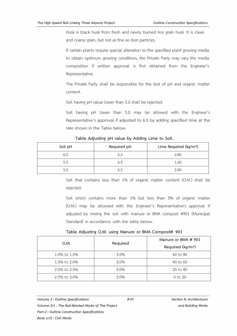
The High Speed Rail Linking Three Airports Project Outline Construction Specifications
Volume 3 : Outline Specifications 8-91 Section 8: Architectural Volume 3/1 : The Rail-Related Works of The Project and Building Works Part 2 : Outline Construction Specifications Book 1//2 : Civil Works
Husk is black husk from fresh and newly burned rice grain husk. It is clean and coarse grain, but not as fine as dust particles.
If certain plants require special alteration to the specified plant growing media to obtain optimum growing conditions, the Private Party may vary the media composition if written approval is first obtained from the Engineer’s Representative.
The Private Party shall be responsible for the test of pH and organic matter content.
Soil having pH value lower than 5.0 shall be rejected.
Soil having pH lower than 5.0 may be allowed with the Engineer’s Representative’s approval if adjusted to 6.5 by adding specified lime at the rate shown in the Table below.
Table Adjusting pH value by Adding Lime to Soil.
Soil pH Required pH Lime Required (kg/m³)
6.0 6.5 0.80 5.5 6.5 1.60 5.0 6.5 2.40
Soil that contains less than 1% of organic matter content (O.M.) shall be rejected.
Soil which contains more than 1% but less than 3% of organic matter (O.M.) may be allowed with the Engineer’s Representative's approval if adjusted by mixing the soil with manure or BMA compost #901 (Municipal Standard) in accordance with the table below.
Table Adjusting O.M. using Manure or BMA Compost# 901
O.M. Required Manure or BMA # 901
Required (kg/m³) 1.0% to 1.5% 3.0% 60 to 80 1.5% to 2.0% 3.0% 40 to 60 2.0% to 2.5% 3.0% 20 to 40 2.5% to 3.0% 3.0% 0 to 20

The High Speed Rail Linking Three Airports Project Outline Construction Specifications
Volume 3 : Outline Specifications 8-92 Section 8: Architectural Volume 3/1 : The Rail-Related Works of The Project and Building Works Part 2 : Outline Construction Specifications Book 1//2 : Civil Works
Submit soil sample to Engineer’s Representative for approval one (1) month prior to placement.
(6) Commercial fertilizer shall be a complete formula 16-16-16, applied at the rate of 12 kg. per 100 sq.m. uniform in composition, free flowing and suitable for application with approved equipment, delivered to the site in unopened containers, each fully labeled, and each bearing the name or mark of the manufacturer. Thoroughly roto-till at a depth of at least 20 cm after applying fertilizer.
(7) Conditions
All trees, shrubs, vines, and groundcover shall have a normal habitat of growth and shall be sound, healthy, vigorous and free from insect infestations.
The minimum size of all trees and shrubs measured after pruning, with branches in normal positions, shall conform to the measurements specified on the Plant List.
Caliper measurement shall be taken at a point on the trunk 30 cm. above natural ground line. Coconut trees (and other palm if used) will be measured in unit of height in meters from ground level to center of crown shaft (not overall height) unless otherwise noted.
Plants that meet the measurements specified, but do not possess a normal configuration or balance of height and spread will be rejected.
Trees and shrubs larger in size than specified may be used. Height shall not be substituted for balanced form.
Trees shall have been grown in container type which facilitates their easy removal from the container and causes no damage to root structures.
Trees and shrubs shall have been grown in containers which have sufficient roots to hold the root ball together after removal from containers without being root bound.
Specimen, field grown and field stock palms and trees shall have a root ball of specified size.

The High Speed Rail Linking Three Airports Project Outline Construction Specifications
Volume 3 : Outline Specifications 8-93 Section 8: Architectural Volume 3/1 : The Rail-Related Works of The Project and Building Works Part 2 : Outline Construction Specifications Book 1//2 : Civil Works
Any tree or shrub with weak, thin trunk not capable of supporting itself when planted in the open will be rejected.
Trees shall be straight and of uniform shape without damaged, crooked, or multiple leaders, unless specified. Trees with abrasions of the bark, sun scalds, disfiguring knots, or fresh cuts of limbs over ½ inch which have not been pruned and painted or completely callused, will be rejected.
Rooted cuttings shall be healthy, vegetative material with well-established roots at one or more nodes.
(8) Ball sizes
The following ball sizes are the minimum recommended for nursery grown plants. Plants collected from wild or native stands must have minimum ball sizes equal to those recommended for the next larger size nursery grown stock.
Table Shade Tree Ball Dimensions
Tree Caliper Size (cm.) Ball Diameter (cm.) Ball Depth (cm.)
2.0 to 2.5 35 24 2.5 to 3.0 40 28 3.0 to 4.0 45 30 4.0 to 4.5 50 33 4.5 to 5.0 55 36 5.0 to 6.0 58 39 6.0 to 7.5 70 44 7.5 to 9.0 80 47 9.0 to 10.0 95 50 10.0 to 11.5 105 60 11.5 to 13.0 120 68 13.0 to 14.0 135 75
Any tree having caliper greater than 15 cm. is not recommended to be transplanted unless otherwise approved by the Engineer’s Representative.
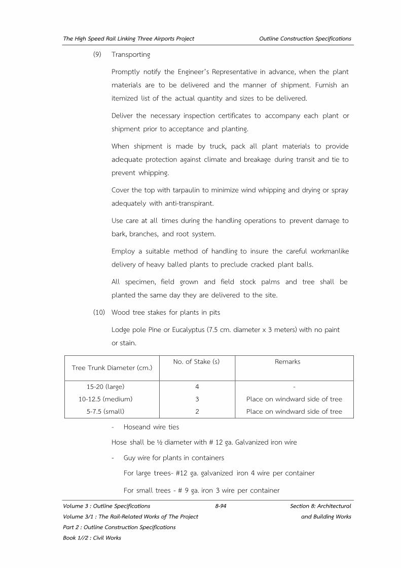
The High Speed Rail Linking Three Airports Project Outline Construction Specifications
Volume 3 : Outline Specifications 8-94 Section 8: Architectural Volume 3/1 : The Rail-Related Works of The Project and Building Works Part 2 : Outline Construction Specifications Book 1//2 : Civil Works
(9) Transporting
Promptly notify the Engineer’s Representative in advance, when the plant materials are to be delivered and the manner of shipment. Furnish an itemized list of the actual quantity and sizes to be delivered.
Deliver the necessary inspection certificates to accompany each plant or shipment prior to acceptance and planting.
When shipment is made by truck, pack all plant materials to provide adequate protection against climate and breakage during transit and tie to prevent whipping.
Cover the top with tarpaulin to minimize wind whipping and drying or spray adequately with anti-transpirant.
Use care at all times during the handling operations to prevent damage to bark, branches, and root system.
Employ a suitable method of handling to insure the careful workmanlike delivery of heavy balled plants to preclude cracked plant balls.
All specimen, field grown and field stock palms and tree shall be planted the same day they are delivered to the site.
(10) Wood tree stakes for plants in pits
Lodge pole Pine or Eucalyptus (7.5 cm. diameter x 3 meters) with no paint or stain.
- Hoseand wire ties
Hose shall be ½ diameter with # 12 ga. Galvanized iron wire
- Guy wire for plants in containers
For large trees- #12 ga. galvanized iron 4 wire per container
For small trees - # 9 ga. iron 3 wire per container
Tree Trunk Diameter (cm.) No. of Stake (s)
Remarks
15-20 (large) 10-12.5 (medium)
5-7.5 (small)
4 3 2
- Place on windward side of tree Place on windward side of tree
The High Speed Rail Linking Three Airports Project Outline Construction Specifications
Volume 3 : Outline Specifications 8-95 Section 8: Architectural Volume 3/1 : The Rail-Related Works of The Project and Building Works Part 2 : Outline Construction Specifications Book 1//2 : Civil Works
8.13.4 Site Concrete
(1) Concrete shall be composed of Portland cement, fine aggregates, coarse aggregate, water and admixtures, as specified, and shall be made at the site of the work, except as otherwise authorized in writing by the Engineer’s Representative. Central mix or transit mix concrete may be permitted, provided it can be placed within the time requirements specified, and complies with all of the provisions herein specified.
(2) Reinforced Concrete and workmanship shall conform to ACI 318, Building Code Requirements for Reinforced Concrete.
(3) Methods of testing will comply in detail with the applicable ASTM Methods of Test.
8.13.5 Structural Steelwork
(1) Field Connections
Field connections shall be made by welding or high-strength bolting as shown on the drawings or approved shop drawings.
(2) Welding
Welding shall be in accordance with the Standard Specifications of the AWS.
The Private Party may substitute field bolting where field welding is shown, provided bolting details have shop drawing approval.
(3) Bolting
High-strength bolts shall conform to the Specifications for the Assembly of Structural Joints using High-Strength Steel Bolts, as approved by the Research Council on Riveted and Bolted Structural Joints of the Engineer’s Representative Foundation or JIS B1186, "Sets of High Strength Hexagon Bolts, Hexagon Nuts and Plain Washers for Friction Grip Joints".
Anchor bolts shall be of mild steel with hexagonal nuts. Threads shall be clean cut and conform to ANSI, B 1.1, "Unified Screw Threads", coarse thread UNC, class 3A or JIS B0205, "Metric Coarse Screw Threads"

The High Speed Rail Linking Three Airports Project Outline Construction Specifications
Volume 3 : Outline Specifications 8-96 Section 8: Architectural Volume 3/1 : The Rail-Related Works of The Project and Building Works Part 2 : Outline Construction Specifications Book 1//2 : Civil Works
Anchor bolts shall be accurately set before the concrete is poured unless specifically permitted otherwise by the Engineer’s Representative. To facilitate the setting of anchor bolts, the Private Party shall utilize screed plates. The Private Party may substitute wooden template in lieu of screed upon written approval.
Anchor bolts with pipe sleeves shall be in accordance with the details shown on the drawings.
Bolt anchors shall be of the cinch, raw 1 or slug-in type. Anchors shall be minimum two unit type.
Bolt and nut threads shall be galvanized and shall conform to ANSI B 1.1, class 2A or JIS B0205
(4) Shear Connector Studs
Steel shear connector studs shall be of the diameter and spacing shown.
(5) Painting
- Shop Painting
All structural steel shall be given shop primer after fabrication and cleaning but before shipping in accordance with the standard Specifications.
All steel work shall be thoroughly cleaned of all loose mill scale, rust, and foreign matter before shop painting. Each individual piece shall be painted prior to assembly. Edges where field welding is required shall not be painted.
Paint shall be applied only to dry surfaces.
- Field painting
After erection the Private Party shall thoroughly prepare and clean the entire surface of all structural steel of all dirt, grease, rust or other foreign matter. The entire surface of all members shall be field painted as specified in the Standard.
The High Speed Rail Linking Three Airports Project Outline Construction Specifications
Volume 3 : Outline Specifications 8-97 Section 8: Architectural Volume 3/1 : The Rail-Related Works of The Project and Building Works Part 2 : Outline Construction Specifications Book 1//2 : Civil Works
8.14 MISCELLANEOUS
8.14.1 Intumescent Fireproofing
8.14.1.1 The material and installation shall conform the applicable building code requirements of all authorities having jurisdiction
8.14.1.2 Regulation Requirements Conform to Thai Building code No.60 for fire resistance rating.
8.14.1.3 References
(1) Tested in Accordance with BS476: Part 20:1987 Method for determination at the Fire resistance element at construction general principles and Part 21 · 1987 Method for determination of load bearing element of construction
(2) ASTM E119. Standard Test Method for Fire test of Building Construction and Materials
(3) Din 5 1755. Flash point
(4) ISO 9002; 1994 Quality System certificate of Manufacturer
(5) CE certification
(6) ENV 13381-4 The European Norm
8.14.1.4 Warranty
(1) Provide 10 years warranty
(2) Submit a written warranty for work under this Section for 10 years
8.14.1.5 Materials
Fireproofing material to be used shall be “Intumescent” system. The System shall consists of:
(1) Compatible anti-corrosion primer (Red Lead, Red Oxide Primer or Alkyd Primer)
(2) Intumescent basecoat
(3) Compatible decorative topcoat
The High Speed Rail Linking Three Airports Project Outline Construction Specifications
Volume 3 : Outline Specifications 8-98 Section 8: Architectural Volume 3/1 : The Rail-Related Works of The Project and Building Works Part 2 : Outline Construction Specifications Book 1//2 : Civil Works
8.14.1.6 The Intumescent basecoat shall have the following typical property ranges:
(1) Single component solvent base, consisting of acrylic polymers
(2) Fire test in accordance with BS 476 part 21 (British Standard "Fire Test on Building Materials and Structures") or equivalent.
(3) Suitable for interior
(4) Excellent long term durability
(5) Can be applied up to 1200 micron (Dry film) by three coats by brush.
8.14.2 Cementitious Fireproofing
8.14.2.1 The work is subject to applicable portions of the following standards:
(a) ASTM E84 "Test Method for Surface Burning Characteristics of Building Materials", American Society for Testing and Materials
(b) ASTM E119 "Method for Fire Test of Building Construction and Materials", American Society for testing and Materials
(c) ASTM E605 '"Test method for Thickness and Density of Sprayed Fire-Resistive Material Applied to Structural Members", American Society for Testing and Materials. The dry density is 220-240 kg/cu.m for low density and 350 kg/ cu.m for medium density
(d) ASTM E699 "Practice for Criteria for Evaluation of Agencies Involved in Testing, Quality Assurance, and Evaluating Building Components in Accordance with Test Methods promulgated by ASTM Committee E-6", American Society for Testing and Materials.
(e) ASTM E736 “Test Method for Adhesion/Cohesion of Sprayed Fire-Resistive Materials Applied to Structure Members”, American Society for Testing and Materials
(f) AWCI Technical Manual 12-A "Standard Practice for the Testing and Inspection of Field Applied Sprayed Fire-Resistive materials; an annotated Guide" Association of Wall and Ceiling Industries, International
(g) UL "Building Materials Directory", Underwriters' Laboratories, Inc
(h) UL "Fire Resistance Directory", Underwriters' Laboratories, Inc

The High Speed Rail Linking Three Airports Project Outline Construction Specifications
Volume 3 : Outline Specifications 8-99 Section 8: Architectural Volume 3/1 : The Rail-Related Works of The Project and Building Works Part 2 : Outline Construction Specifications Book 1//2 : Civil Works
8.14.2.2 Regulatory Requirements
(1) Conform to Thai Building Code no.60 for fire resistance ratings. Submit certification of acceptability of fireproofing materials to the Engineer’s Representative.
(2) Apply fireproofing material in thicknesses necessary to obtain a two hour fire resistance rating for steel deck flooring as required by local building code unless otherwise indicated.
(3) Apply fireproofing material in thicknesses necessary to obtain a three hour fire resistance ratings for columns, beams, roof beams, stair beams, stringer, rafter, trusses, as required by local building code unless otherwise indicated.
8.14.2.3 Submittals
(1) Submit manufacturer's product data with application and installation instructions for all products in accordance with the required submittals. Product data shall include certifications and test reports necessary to show compliance with the Contract Documents:
(a) Certification by manufacturers that products supplied complies with Fire test data Reliable Laboratory according to the standard of ASTM E119 (Test method for Fire Tests of Building Construction and Material.).
(2) Submit Shop Drawings, in form of structural framing plans, and indicating the following:
(a) Locations and type of surface preparations are required before applying fireproofing
(b) Extent of sprayed-on fireproofing for each different construction and fire-resistance rating.
(3) Applicable fire-resistive design designations of inspecting and testing agency acceptable to authorities having jurisdiction.
(a) Minimum thicknesses needed to achieve required fire-resistance ratings of structural components and assemblies.
(b) Treatment of fireproofing after its application.

The High Speed Rail Linking Three Airports Project Outline Construction Specifications
Volume 3 : Outline Specifications 8-100 Section 8: Architectural Volume 3/1 : The Rail-Related Works of The Project and Building Works Part 2 : Outline Construction Specifications Book 1//2 : Civil Works
(c) Confirm that the Drawings indicate where the fire protection is to be installed. The use of marked plan view drawings is recommended.
(4) Samples for initial selection: manufacturer's color charts showing the full range of colors and glosses available.
(5) Samples for verification: each type of exposed finish required, prepared on 2 samples, each 300 mm square, of each color, gloss, texture and material formulation to be applied. Where finishes involve normal color and texture variations, include Sample sets showing the full range of variations expected.
(6) Product certificates: signed by manufacturer of sprayed fire-resistive material certifying that the products furnished comply with requirements.
(7) Installer certificates: signed by manufacturer certifying that installers comply with specified requirements.
(8) Qualification data: for firms and persons specified in "Quality Assurance" Article to demonstrate their capabilities and experience. Include list of completed projects with project names and addresses, names and addresses of the Engineer’s Representative and the SRT, and other information specified.
(9) Compatibility and adhesion test reports: for primers and other coatings applied to structural steel. Provide reports from a qualified independent testing and inspecting agency engaged by the Private Party. Confirm that primers and coatings proposed for application in shop or field are compatible with fire-resistive material. Instruct laboratory to determine compatibility according to requirements specified in "Quality Assurance" Article.
(10) Product test reports: indicate that physical properties of proposed sprayed fire- resistive materials comply with specified requirements based on comprehensive testing of current product formulations by a qualified testing and inspecting agency according to requirements specified in "Quality Assurance" Article.
(11) Research/evaluation reports: evidence of sprayed fire-resistive material’s compliance with the building code in effect for project, from an organization acceptable to authorities having jurisdiction.
The High Speed Rail Linking Three Airports Project Outline Construction Specifications
Volume 3 : Outline Specifications 8-101 Section 8: Architectural Volume 3/1 : The Rail-Related Works of The Project and Building Works Part 2 : Outline Construction Specifications Book 1//2 : Civil Works
(12) Prepare a 600 mm x 600 mm sample application of each fireproofing material in the building. After inspection, the samples shall remain in place as a guide for entire work.
8.14.2.4 Quality Assurance
(1) Before starting the work, arrange a pre-construction meeting with the Engineer’s Representative, the Private Party, installer, and manufacturer to discuss construction procedure, specifications, surface readiness, application, and material storage and protection. Conduct meeting in accordance with the project meeting requirements.
(2) Professional engineer qualifications: a professional engineer who is legally qualified to practice in the jurisdiction where Project is located and who is experienced in providing engineering services of the kind indicated. Engineering services are defined as those performed for installations of sprayed fire-resistive materials that are similar to those indicated for this Project in material, design, and extant.
(3) Testing agency qualifications: an independent testing and inspecting agency with the experience and capability to conduct the testing indicated without delaying the Work.
(4) Testing of fire-resistive materials: by a qualified testing and inspecting agency engaged by the Private Party or manufacturer according to the following requirements:
(a) Sprayed fire-resistive materials are randomly selected for testing from bags bearing the applicable classification marking of UL or another testing and inspecting agency acceptable to authorities having jurisdiction.
(b) Testing is performed on specimens of sprayed fire-resistive materials that comply with laboratory testing requirements specified and are otherwise identical to installed fire-resistive materials, including application of accelerant, sealers, topcoats, tamping, troweling, rolling, and water overspray, if any of these are used in final application.

The High Speed Rail Linking Three Airports Project Outline Construction Specifications
Volume 3 : Outline Specifications 8-102 Section 8: Architectural Volume 3/1 : The Rail-Related Works of The Project and Building Works Part 2 : Outline Construction Specifications Book 1//2 : Civil Works
(c) Testing is performed on specimens whose application the independent testing and inspecting agency witnessed during preparation and conditioning. Include in test reports a full description of preparation and conditioning of laboratory test specimens.
(5) Testing for compatibility and adhesion: engage a qualified testing and inspecting agency to prepare compatibility and adhesion test reports required by the Engineer’s Representative that complies with the following requirements:
(a) Testing for bond per ASTM E736 and requirements specified in UL's "Fire Resistance Directory” about coating materials.
(b) Verify that manufacturer of fire-resistive material-has not found primers or coatings to be incompatible with fire-resistive material based on its own laboratory testing or field experience.
(6) Source limitations: obtain each type of sprayed fire-resistive material from one source and by a single manufacturer.
(7) Fire-test-response characteristics: provide sprayed-on fireproofing products identical to those used in assemblies tested for the following fire-test-response characteristics, per test method indicated below, by UL or another testing and inspecting agency acceptable to authorities having jurisdiction. Identify packages (bags) containing fireproofing with appropriate classification markings of applicable testing and inspecting agency.
(8) Installer qualifications: engage an experienced installer certified, licensed, or otherwise qualified by the sprayed-on fireproofing manufacturer as having the necessary experience, staff, and training to install manufacturer's products per specified requirements. A manufacturer's willingness to sell its sprayed-on fireproofing products to the Private Party or to an installer engaged by the Private Party does not in itself confer qualification on the buyer.
(9) Field-constructed mockups: prior to installing sprayed-on fireproofing, apply each product specified for exposed applications to demonstrate both aesthetic effects and qualities of materials and execution. Build mockups to comply with the following requirements, using materials indicated for final unit of Work.
The High Speed Rail Linking Three Airports Project Outline Construction Specifications
Volume 3 : Outline Specifications 8-103 Section 8: Architectural Volume 3/1 : The Rail-Related Works of The Project and Building Works Part 2 : Outline Construction Specifications Book 1//2 : Civil Works
(a) Locate mockups on site in location or, if not indicated, directed by the Engineer’s Representative.
(b) Extent of mockups: approximately 9 sq. m of surface for each product indicated.
(c) Notify the Engineer’s Representative one week in advance of the dates and times when mockups will be erected.
(d) Demonstrate the proposed range of aesthetic effects and workmanship
(e) Obtain the Engineer’s Representative's acceptance of mockups before start of final unit of Work.
(f) Retain and maintain mockups during construction in undisturbed condition as a standard for judging completed unit of Work.
(10) Acceptable mockups in undisturbed condition at time of substantial completion may become part of completed unit of Work.
(11) Before proceeding with the fire protection work, approved of the proposed material thicknesses and densities shall be obtained from the Engineer’s Representative and other applicable authorities.
8.14.3 Sheet Membrane Waterproofing
8.14.3.1 References
(1) EN12311-2 - Plastic and rubber sheets for roof waterproofing
(2) EN 1928(A) - Determination of water tightness
(3) EN 12730(B) - Determination of resistance to static loading
(4) EN 12691 - Determination of resistance to impact
(5) EN 12310-2 - Determination of resistance to tearing
(6) EN 12316-2 - Determination of peel resistance of joints
(7) EN 12317-2 - Determination of shear resistance of joints
(8) EN 1297 - Method of artificial ageing by long term exposure to the combination of UV radiation, elevated temperature and water

The High Speed Rail Linking Three Airports Project Outline Construction Specifications
Volume 3 : Outline Specifications 8-104 Section 8: Architectural Volume 3/1 : The Rail-Related Works of The Project and Building Works Part 2 : Outline Construction Specifications Book 1//2 : Civil Works
(9) EN 495-5 -Determination of fold ability at low temperature
(10) EN 13501-1 - Classification using data from reaction to fire tests
(11) EN 13501-5 - Classification using data from external fire exposure to roofs tests
(12) EN 13948 -Determination of resistance to root penetration
8.14.3.2 System Description
Waterproofing System: The systems are fully adhered directly to an acceptable substrate using Bonding Adhesive. Adjoining sheets are overlapped a minimum of 75 mm and the seams are heats-welded to form a continuous, watertight membrane.
8.14.3.3 Submittals
(1) Shop Drawings: Indicate special joint or termination conditions and conditions of interface with other materials.
(2) Product Data: Provide data for surface conditioner flexible flashings, joint cover sheet, and joint and crack sealants, with temperature range for application of waterproofing membrane.
(3) Manufacturer's Installation Instructions: Indicate special procedures and perimeter conditions requiring special attention.
(4) Manufacturer's Certificate: Certify that products meet or exceed specified requirements
8.14.3.4 Quality Assurance
(1) Perform Work in accordance with NRCA Waterproofing Manual.
(2) Maintain one copy of each document on site.
8.14.3.5 Qualifications
(1) Membrane Manufacturer: Company specializing in waterproofing sheet membranes with minimum 10 years experience.
(2) Applicator: Company specializing in performing the Works of this section with minimum 5 years documented experience manufacturer.
The High Speed Rail Linking Three Airports Project Outline Construction Specifications
Volume 3 : Outline Specifications 8-105 Section 8: Architectural Volume 3/1 : The Rail-Related Works of The Project and Building Works Part 2 : Outline Construction Specifications Book 1//2 : Civil Works
8.14.3.6 Warranty
(1) Provide 10 years warranty.
(2) Warranty: Include coverage for waterproofing failing to resist penetration of water, except where such failures are the result of structural failures of building. Hairline cracking of concrete due to temperature change of shrinkage is not considered a structural failure.
(3) Warranty: Include coverage for waterproofing failing to resist penetration of water.
8.14.3.7 Products
(1) Membrane Materials
The single-ply Thermoplastic Polyolefin membrane made from the incorporation of an ethylene propylene rubber into a polypropylene matrix and produced with a polyester weft inserted reinforcement.
(2) Adhesive Materials
Surface Conditioner: To be compatible with membrane.
Adhesives: As recommended by membrane manufacturer.
Thinner and Cleaner· As recommended by adhesive manufacturer, compatible with sheet membrane.
8.14.4 Cementitious Waterproofing
8.14.4.1 Submittals
(1) Product Data: Provide details of product description, test performed, limitations of coating, cautionary procedures required during application.
(2) Manufacturer's Installation Instructions: Indicate special procedures and conditions requiring special attention.
(3) Manufacturer's Certificate: Certify that products meet or exceed specified requirements.
The High Speed Rail Linking Three Airports Project Outline Construction Specifications
Volume 3 : Outline Specifications 8-106 Section 8: Architectural Volume 3/1 : The Rail-Related Works of The Project and Building Works Part 2 : Outline Construction Specifications Book 1//2 : Civil Works
8.14.4.2 Qualifications
(1) Manufacturer: Company specializing in manufacturing the product specified in this section with minimum 3 years documented experience.
(2) Applicator: Company specializing in performing the work of this section with minimum 3 years documented experience manufacturer
8.14.4.3 Materials
(1) Coating: Cementitious waterproof coating.
(2) Mixing: Mix cement-based waterproof coating with mixing liquid in accordance with manufacturer's instructions.
The High Speed Rail Linking Three Airports Project Outline Construction Specifications
Volume 3 : Outline Specifications 9-1 Section 9: Tunneling Works Volume 3/1 : The Rail-Related Works of The Project Part 2 : Outline Construction Specifications Book 1//2 : Civil Works
SECTION 9: TUNNELING WORKS
9.1 TUNNEL EXCAVATIONS (NATM)
9.1.1 Introduction and Scope of Work
This Section covers all excavation work and lining for tunnel to be constructed under this Contract performed using drilling and blasting or in exceptional cases by manual means.
The Work of this outline construction specification shall include all drilling and blasting, loading, transporting, and disposal of materials in spoil or stockpile areas, as well as the removal of all loose material and cleaning of excavated surfaces.
Excavation shall be made to the lines, grades and dimensions shown on the consented Working Drawings or as otherwise directed by the SRT’s Representative.
The Private Party may be required to perform exploratory drilling during excavation of the tunnels and shafts.
9.1.2 Submittal of Method Statement
The Private Party shall prepare and submit to the SRT’s Representative the detailed methods of excavation concerning each section of work at least twenty eight (28) days before starting the excavation activities.
These methods shall indicate the equipment, the phases of excavation, the temporary and primary supports and protections to be used, the estimated progress, the characteristics of the explosives, the distributions and quantities of the charges, the diameter, depth and spacing of holes, the type and number of blasting caps, the firing system, the security measures to be implemented and any other information that can be required by the SRT’s Representative.
To enable the SRT’s Representative to verify all necessary setting-out and elevations carried out by the Private Party, the latter shall notify the SRT’s Representative in writing, giving at least seven (7) days notice, of his intention to start excavation.
The High Speed Rail Linking Three Airports Project Outline Construction Specifications
Volume 3 : Outline Specifications 9-2 Section 9: Tunneling Works Volume 3/1 : The Rail-Related Works of The Project Part 2 : Outline Construction Specifications Book 1//2 : Civil Works
9.1.3 Excavation Lines and Tolerances
Typical cross sections, excavation lines, and dimensions of excavations are shown on the Conceptual Drawings. The design lines are the minimum excavation lines within which no rock material will be permitted to remain.
The Private Party shall take into account the grade and alignment inexactness of the excavation by his excavating equipment, and shall guarantee that the theoretical thickness of the concrete lining is never reduced. All out-of-line excavations shall be rectified so that the design lines are maintained.
With regard to the final linings, the minimum thicknesses shown on the consented Working Drawings shall be maintained.
The acceptable tolerance on the position of the internal profile of the tunnel lining is related to its internal diameter. The position shall be such that the track alignment, inclusive of its positional tolerance and clearance gauges, as shown on the Conceptual Drawings. If the actual internal diameter is equal to the nominal internal diameter, the internal profile of the lining shall not depart from its design position by more than 75mm.
Excavation shall be executed with care in order to limit as much as possible the over-break behind the design lines shown in the Drawings.
Excavation not shown on the consented Working Drawings, but which the Private Party considers necessary for this own purposes, shall be backfilled with the approved concrete up to the design lines prior to commencement of the final lining.
The Private Party shall use every precaution in the performance of this work to minimise loosening material and progressive deterioration of the in-place material surrounding the excavation. Any damage to or displacement of tunnel supports and any other part of the Work caused by blasting or any other operations of the Private Party shall be repaired in an approved manner.
All material projecting within the design lines except permanent steel supports shown on the consented Working Drawings or required by the SRT’s Representative to remain in place, shall be removed by the Private Party, prior to placing of concrete.
The High Speed Rail Linking Three Airports Project Outline Construction Specifications
Volume 3 : Outline Specifications 9-3 Section 9: Tunneling Works Volume 3/1 : The Rail-Related Works of The Project Part 2 : Outline Construction Specifications Book 1//2 : Civil Works
9.1.4 Geotechnical and Geological Investigations
Geotechnical, geomechanical and hydrological factors are very important to determine the degree of difficulty and cost of construction. The Private Party may be required to perform additional exploratory drilling during excavation of the tunnels and shafts and shall inform the SRT’s Representative about his planned investigations including a full description of equipment and procedures and, at regular meetings, about the progress and preliminary results of ongoing investigations. The Private Party shall submit the ground investigation reports to the SRT’s Representative after completion of the investigations. In brief, the types of information that must be obtained can be classified as follows:
Geologic profile (stratigraphy, structure and identification of principal rock types and their general characteristics).
Rock mass characteristics and geomechanical properties.
Hydrogeology (groundwater reservoirs, aquifers and pressure).
Exposure to construction risk (major water-bearing faults, methane gas, etc.).
Information useful for the planning and execution of geotechnical investigation for tunnel and shafts refer to USACE’s SRTing Manual 1110-1-1804, Geotechnical investigations, and EM 110-1-1802, Geophysical Exploration.
Concurrently with the excavation, the Private Party shall map the geological conditions along the tunnels. This mapping and related information will be used to confirm the classification of the rock, the choice of rock support and in the design of the final lining.
The excavation shall be classified using Bieniawski’s RMR or Q-System classification, mapping all visible features and recording water inflow.
9.1.5 Supports for Underground Excavation
The provisional or permanent supports for the underground excavation shall principally consist of shotcrete reinforced with wire mesh or steel fibres as primary element, supplemented with pattern rock bolts.
The High Speed Rail Linking Three Airports Project Outline Construction Specifications
Volume 3 : Outline Specifications 9-4 Section 9: Tunneling Works Volume 3/1 : The Rail-Related Works of The Project Part 2 : Outline Construction Specifications Book 1//2 : Civil Works
During the progress of work, the Private Party shall decide on the kind of supports to be used, stretch by stretch, based on geotechnical evaluations of the rock conditions and following consultation with the SRT’s Representative.
The Private Party shall employ a person (or persons), who by their schooling, knowledge and experience in supporting work qualify to act as Support Delegate(s). The Support Delegate(s) shall examine the rock conditions after each excavation advance and shall verify that the rock support system is installed as ordered. The Support Delegate(s) shall carry sufficient rank to be able to order installation of additional supports or to stop further advance if, in his opinion, the conditions are unsafe. The Support Delegate(s) shall be continuously present and inspect each heading face throughout the duration of underground excavation work. The table below presents the minimum requirement, but not be limited to, for the Private Party’s tunneling staff.
Position Number Experience
(a) NATM Tunneling Manager 1 10 years
(b) NATM Tunneling Engineer 1 per party, per shift 5 years
(c) NATM Tunneling Foreman 1 per party, per shift 10 years
(d) Senior M&E Manager 1 per party, per shift 5 years
The required supports shall be installed without delay during the process of excavation within the heading zone. In the rear zone additional supports shall be installed immediately after it is observed that the supporting system previously installed is not sufficient to prevent further loosening of the material surrounding the excavation.
Shotcrete and Gunite, reinforced or unreinforced with steel wire mesh or steel fibre, shall be applied to excavated surfaces in accordance with the provisions of this Specification. The Private Party shall take into account in his construction planning that placing of gunite or shotcrete protection may be required immediately after blasting a round.
Rockbolts, wire mesh, lattice girders, forepoling and structural steel supports shall be installed in accordance with the provisions of this Specification.
The High Speed Rail Linking Three Airports Project Outline Construction Specifications
Volume 3 : Outline Specifications 9-5 Section 9: Tunneling Works Volume 3/1 : The Rail-Related Works of The Project Part 2 : Outline Construction Specifications Book 1//2 : Civil Works
The Private Party shall keep on the Site all necessary plant and equipment for installing rockbolts and sprayed concrete, ready for operation in the heading zone during the whole excavation period.
9.1.6 Shotcrete
9.1.6.1 General
9.1.6.1.1 Scope of Work
The Work under this Section includes all labour, materials, equipment and services required for the execution of shotcrete work to be carried out by the Private Party under this Contract.
Shotcrete shall be applied to excavated tunnel surfaces, where shown on the consented Working Drawings or as directed by the SRT’s Representative.
The Private Party shall design the mix, furnish materials, place, cure and test shotcrete as necessary to provide temporary or permanent protection and/or support of excavated surfaces.
The Private Party shall furnish all materials, labour and equipment for preparing test panels, both for trial mixes and during the course of the Work, and for testing cores from panels or from in-situ shotcrete.
When the shotcrete is applied as a temporary rock supporting or protection measure, the number and thickness of layers to be applied shall be governed by the prevailing rock conditions.
Shotcrete shall be placed with or without steel wire mesh reinforcement, as directed, and may be used in conjunction with rockbolts, steel ribs and other rock supporting measures.
Where applicable, shotcrete with wire mesh may be replaced by shotcrete with steel fibres which has been mixed into the concrete mix with equipment specifically for that purpose.
The Private Party shall maintain adequate stockpiles of materials for shotcrete for immediate use in cases of emergency.
The High Speed Rail Linking Three Airports Project Outline Construction Specifications
Volume 3 : Outline Specifications 9-6 Section 9: Tunneling Works Volume 3/1 : The Rail-Related Works of The Project Part 2 : Outline Construction Specifications Book 1//2 : Civil Works
9.1.6.1.2 Definitions
Shotcrete is a mixture of cement, aggregate, water and accelerators in correct proportions, projected at high velocity from a nozzle into place to produce a dense homogeneous mass.
9.1.6.1.2.1Gunite
Gunite is a term used for a shotcrete where the maximum aggregate size is less than 4.75 mm. It will be used mainly as a thin protection against loosening of rock surfaces immediately after excavation.
9.1.6.1.2.2 Shotcrete
Shotcrete is a term used for shotcrete where the maximum aggregate size is greater than 4.75 mm. It can be applied with or without admixtures, and will mainly be used for protection and supporting rock surfaces after excavation. It may also be used to fill the cavities caused by overbreaks or weathering.
9.1.6.1.2.3 Dry-Mix Process
In dry-mix process, the cement, aggregates and accelerator batched by weight or volume, are thoroughly mixed dry (with enough moisture to prevent dusting) and fed into a purpose-made machine wherein the mixture is pressurised, metered into a dry air stream and conveyed through hoses or pipes to a nozzle in which water as a spray is introduced to hydrate the mix which is projected without interruption into place.
9.1.6.1.2.4 Wet-Mix Process
In the wet-mix process, all materials and water, but without accelerators, are mixed together to produce mortar or concrete. The mixture is then conveyed by positive displacement or compressed air to a nozzle where air, and possibly accelerator, is injected to increase velocity, and projected without interruption into place.
9.1.6.1.2.5Flash Coat
Flash coat is a term used for shotcrete applied as a thin layer protecting, priming or finishing the surface.
The High Speed Rail Linking Three Airports Project Outline Construction Specifications
Volume 3 : Outline Specifications 9-7 Section 9: Tunneling Works Volume 3/1 : The Rail-Related Works of The Project Part 2 : Outline Construction Specifications Book 1//2 : Civil Works
9.1.6.1.2.6 Layer
Layer is a term used for a discrete thickness of shotcrete built up from a number of passes of the nozzle and allowed to set.
9.1.6.1.2.7 Rebound
Rebound is a term used for all material which, having passed through the nozzle, does not adhere to the target surface.
9.1.6.1.3 Submittals
Before commencing any shotcreting work, the following submittals shall be made for approval:
a) Details, including numbers and type of equipment proposed for mixing and applying the shotcrete
b) Qualifications and experience of the proposed personnel (foremen, nozzlemen and delivery equipment operatives)
c) Manufacturers' certificates giving full details of any proposed admixture, and the Private Party's proposal regarding the use of such admixtures, including certification of harmlessness to operatives
d) The Private Party's proposed mix proportions prior to the commencement of testing and work
e) Details of methods to be employed for controlling the thickness of the layers of shotcrete applied (e.g. plug gauges or boreholes)
9.1.6.2 Materials
9.1.6.2.1 General
Cement, aggregates, water, admixtures, and reinforcement shall conform to the requirements of OCS Section 5 - “Concrete”, except as specifically amended hereafter.
9.1.6.2.2 Aggregates
Aggregate gradation used in gunite or shotcrete shall conform to those established by the preconstruction trial mix tests. The gradation shall not be changed without the prior approval of the SRT’s Representative.

The High Speed Rail Linking Three Airports Project Outline Construction Specifications
Volume 3 : Outline Specifications 9-8 Section 9: Tunneling Works Volume 3/1 : The Rail-Related Works of The Project Part 2 : Outline Construction Specifications Book 1//2 : Civil Works
The following aggregate gradation shall be taken as a guide for mix design purposes, but may be modified, subject to the results of the trial mix tests specified hereinafter:
Gunite 0.15 - 4.75 mm 100 %
Shotcrete (a) 0.15 - 4.75 mm 40 % - 50 %
4.75 - 9.50 mm 50 % - 60 %
(b) 0.15 - 4.75 mm 40 % - 50 %
4.75 - 9.50 mm 20 % - 30 %
9.50 - 19.0 mm 30 % - 40 %
No more than 2% of the aggregate, by weight, shall be retained by the U.S. Standard Sieve No.200 (0.075 mm).
Should the nature of the aggregates used during the course of the Work change (e.g. source, rock type, shape) from that used in the trial mix tests, the Private Party shall produce new trial mixes, using the new aggregates.
9.1.6.2.3 Welded Wire Fabric
The shotcrete shall be reinforced with wire mesh or steel fibres, as shown in the consented Working Drawings or as instructed by the SRT’s Representative.
9.1.6.2.4 Steel Fiber Reinforcement
The shotcrete shall be reinforced with wire mesh or steel fibres, as shown in the consented Working Drawings or as instructed by the SRT’s Representative.
Fibres shall be deformed steel fibres produced from mild steel or cold drawn wire and shall be un- galvanised.
Fibres shall be stored in dry sealed containers until ready for use and shall be free from corrosion, oil, grease, chlorides and deleterious materials which may reduce the efficiency of mixing or spraying processes, or which may reduce the bond between the fibres and the shotcrete.
The High Speed Rail Linking Three Airports Project Outline Construction Specifications
Volume 3 : Outline Specifications 9-9 Section 9: Tunneling Works Volume 3/1 : The Rail-Related Works of The Project Part 2 : Outline Construction Specifications Book 1//2 : Civil Works
Fibre type shall be selected on the basis of compliance with EFNARC (European Specification for Sprayed Concrete, 1996) energy absorption test and on the basis of ease of use in the batching, mixing and spraying processes proposed, as demonstrated by site trials to the approval of the SRT’s Representative. Fibres which tend to form fibre balls during batching and mixing shall not be used.
The Private Party may use the fibre of his choice, subject to approval of the SRT’s Representative. The Private Party shall perform tests to establish the actual dose of steel fibre and submit the results of his proposed mix to the SRT’s Representative for approval.
Steel fibre reinforced shotcrete shall have a minimum fibre content in place of 30 kg/m3 and shall conform to EFNARC (European Specification for Sprayed Concrete, 1996) energy absorption class b (700 Joule at 25 mm deflection on a standard 600 mm x 600 mm x 100 mm plate test for hand spraying and 1000 mm x 1000 mm x 100 mm plate test for robot spraying). The strength of steel fibre reinforced shotcrete shall be checked in accordance with the EFNARC (European Specification for Sprayed Concrete, 1996) energy absorption class b (700 Joule at 25 mm deflection on a standard 600 mm x 600 mm x 100 mm/1000 mm x 1000 mm x 100 mm plate test). The approval of the mix proportions shall be based on a minimum of 5 panels per mix.
For every 250 m³ of shotcrete placed 3 cores of dimensions to be fixed by the SRT’s Representative shall be taken and tested to confirm that the in place fibre content is consistent with that of the plate tests used to determine the mix proportions. If the in place fibre content falls below the tested value the Private Party shall increase the dosage of fibres to ensure that the required content in place is reached.
9.1.6.3 Mix Design and Quality Requirements
9.1.6.3.1 General
Gunite and shotcrete mixes shall be designed by the Private Party such that they achieve the strengths specified. The mixes shall be approved by the SRT’s Representative.

The High Speed Rail Linking Three Airports Project Outline Construction Specifications
Volume 3 : Outline Specifications 9-10 Section 9: Tunneling Works Volume 3/1 : The Rail-Related Works of The Project Part 2 : Outline Construction Specifications Book 1//2 : Civil Works
The cylinder compressive strength at 28 days for structural or permanent shotcrete shall be 25 N/mm². The compressive strength after 7 days shall reach 70% of the specified strength at 28 days.
Mixes shall be such that the aggregate gradation and cement content after placing are as those obtained from samples taken from test panels produced from approved trial mixes. All constituents shall be uniformly dispersed throughout the mix. The minimum cement content shall be 400 kg/m³.
The water content of the mixes shall be limited to prevent sloughing. The water-cement ratio of fresh gunite and shotcrete in place shall be between 0.32 and 0.45.
9.1.6.3.2 Admixtures
Accelerator (e.g. Sigunit of SIKA or approved equal) shall be added to the mix to speed-up the setting rate of the cement. Following setting times and strengths shall generally apply unless otherwise stated elsewhere:
a) Initial set of cement/admixture paste 3 min
Final set of cement/admixture paste 12 min
b) 3-hour strength of shotcrete 0.7 N/mm²
8-hour strength of shotcrete 4.0 N/mm²
24-hour strength of shotcrete 10.0 N/mm²
The consumption of admixtures shall be recorded daily. The average content may reach 4.5 %, however the maximum content shall not exceed 6 % of the weight of cement.
9.1.6.4 Testing
9.1.6.4.1 Setting times
The time of setting of the cement/admixture paste shall be determined in accordance with ASTM Test Method C 266 or equivalent

The High Speed Rail Linking Three Airports Project Outline Construction Specifications
Volume 3 : Outline Specifications 9-11 Section 9: Tunneling Works Volume 3/1 : The Rail-Related Works of The Project Part 2 : Outline Construction Specifications Book 1//2 : Civil Works
9.1.6.4.2 Test Panels
Prior to the placing of any shotcrete in the Works, the Private Party shall undertake testing of the trial mixes, in the presence of the SRT’s Representative, using the methods described below.
The Private Party shall prepare three test panels of minimum size 75 x 75 cm and 12 mm thick, for each mix design and for each type of plant. They shall be sprayed from each position required in the Works, one downhand, one horizontal and one overhead with a layer thickness appropriate to that position and with reinforcement as appropriate. Panel moulds shall be formed from plywood at least 20 mm thick, be adequately braced and be held rigidly in position.
For the purpose of routine quality control during the execution of work, control test panels of the same size as for the trial mix testing shall be sprayed. For the first 50 m³ of shotcrete applied in each underground excavation heading, one test panel shall be prepared, further the test panels will be limited to one per nozzleman per week or one per 100 m³ of material placed. The test panels shall be constructed alongside the area of placement and at the same angle and shall be sprayed by each nozzleman in rotation so that the tests shall represent the quality of the shotcrete being placed by each nozzleman. The test panels shall be stored and cured alongside and under similar conditions to the shotcrete placed in the Works.
Concrete from both the trial mix and the routine quality control test panels shall be tested as described hereunder.
9.1.6.4.3 Compression Testing
Four 50 mm diameter cores shall be cut from each test panel at right angles to the plane of the panel approximately 48 hours after the panel has been sprayed. Cores shall not be taken within 10 cm of the edges of the panel.
First core shall be compression tested at 3 days, second core at 7 days, and the remaining two cores at 28 days. The core capping and testing shall be carried out in an approved laboratory.

The High Speed Rail Linking Three Airports Project Outline Construction Specifications
Volume 3 : Outline Specifications 9-12 Section 9: Tunneling Works Volume 3/1 : The Rail-Related Works of The Project Part 2 : Outline Construction Specifications Book 1//2 : Civil Works
The cores shall be stored, cured and tested in accordance with ASTM Standard Method C 42. or equivalent All cores shall be suitably labelled to identify them with the panels from which they have been taken, and the location in the Works to which they relate.
The appropriate compressive strength requirement for each set of two 28-day cores shall be satisfied if:
a) Each core has a compressive strength equal to or greater than that specified, or
b) The average compressive strength of the two cores is equal to or greater than that specified and the difference between the strengths is less than 20 % of the average.
Should any of the cores reveal defects such as a lack of compaction, dry patches, voids or sand pockets, the SRT’s Representative may require further tests or cores to be taken from the remainder of the panel(s) or he may reject the procedure used to make the defective test panel and require that a replacement test panel be made with a modified procedure.
9.1.6.4.4 Other Routine Tests during the Works
When necessary the Private Party shall make 25 mm diameter probe holes to determine the thickness of the shotcrete.
When necessary the Private Party shall cut sets of 50 mm diameter cores from the finished shotcrete, which shall be tested using the same procedure as on cores taken from the test panels.
Core holes shall be filled by hand with well rammed dry-pack mortar of a similar mix to that used for shotcrete
Where necessary the compressive strength of the shotcrete shall be assessed by non- destructive testing using the "Schmidt Concrete Test Hammer", calibrated by reference readings taken on the shotcrete at locations where cores are to be taken. At least ten readings shall be taken for each strength assignment.
Soundness shall be tested by hand hammer. A hollow response indicates a possible lack of bond or other defect.
The High Speed Rail Linking Three Airports Project Outline Construction Specifications
Volume 3 : Outline Specifications 9-13 Section 9: Tunneling Works Volume 3/1 : The Rail-Related Works of The Project Part 2 : Outline Construction Specifications Book 1//2 : Civil Works
The measurement of in-situ penetration resistance shall be carried out using a spring-loaded penetrometer or similar suitable equipment.
9.1.6.5 Execution
9.1.6.5.1 Personnel
Only skilled labour having adequate knowledge of the shotcrete techniques shall be employed for the Work.
A supervising foreman shall be employed full time at the Site. He shall have adequate experience in, and full knowledge of, spraying techniques.
The trial mix test panels shall be sprayed by the proposed nozzlemen. Only when the nozzleman has demonstrated his expertise at the test panels will he be permitted to carry out permanent spraying work.
9.1.6.5.2 Equipment
Only modern, properly operating mixing, delivery, and placing equipment shall be used for the performance of the Work. The Private Party shall make such provisions in his equipment that inclusion of the equipment for mixing steel fibre reinforcement into shotcrete will be possible on request.
The compressor shall provide a supply of air adequate to maintain sufficient nozzle velocity for all parts of the Work while simultaneously operating a blowpipe for clearing away rebound when required.
The delivery equipment shall be a pneumatic feed type or, for the wet-mix process, positive displacement type. The equipment shall be capable of delivering a continuous smooth stream of uniformly mixed material at the proper velocity from the discharge nozzle at all heights of the Work.
The delivery equipment shall be thoroughly cleaned at the end of each shift. Equipment parts, especially the nozzle liner and water ring, shall be regularly inspected and replaced as required.
The discharge nozzle, for the dry-mix process, shall be equipped with a manually operated water injection system (water ring) for directing an even distribution of water to the aggregate-cement mixture. The water valve shall be capable of ready adjustment to vary the quantity of water and shall be convenient for the nozzleman.

The High Speed Rail Linking Three Airports Project Outline Construction Specifications
Volume 3 : Outline Specifications 9-14 Section 9: Tunneling Works Volume 3/1 : The Rail-Related Works of The Project Part 2 : Outline Construction Specifications Book 1//2 : Civil Works
Water pressure shall be maintained at a uniform level which shall be at least 1 bar above operating pressure and sufficient to ensure adequate hydration at all times.
The nozzle shall be capable of delivering a conical uniform discharge stream. Distortion of this stream shall be remedied by examination of the nozzle and any malfunction rectified by replacement of defective parts before further work is carried out.
9.1.6.5.3 Preparation for Placing Shotcrete
9.1.6.5.3.1Rock
The rock surface shall be cleaned of loose material, mud and other foreign matter which might prevent bond of the shotcrete onto the rock surface. After washing down by air-water jetting, the surfaces shall be damp but exhibiting no free water prior to the application of shotcrete.
9.1.6.5.3.2Wet Surface
Where flow of water could interfere with the application of shotcrete or cause leaching of cement, the water shall be led by pipes or gutters to some point where it may be plugged off or allowed to drain after the application of shotcrete.
Stemming small flows by the use of special mixes of shotcrete containing abnormally high proportions of admixtures which will induce accelerated set will be permitted, but such shotcrete shall not be considered to form part of the structural thickness.
9.1.6.5.3.3Steelwork and Steel Reinforcement
The steelwork and reinforcement shall be cleaned of loose rust, oil, scale, paint and any coating or previously deposited rebound material which might prevent a proper bond prior to the application of shotcrete.
Welded wire fabric shall be installed where required.
9.1.6.5.3.4Previously Placed Concrete
Loose and unsound concrete shall be removed before applying shotcrete. The surface shall be damp prior to application of shotcrete. The surface shall be prepared so that no abrupt changes in thickness of the shotcrete occur.
The High Speed Rail Linking Three Airports Project Outline Construction Specifications
Volume 3 : Outline Specifications 9-15 Section 9: Tunneling Works Volume 3/1 : The Rail-Related Works of The Project Part 2 : Outline Construction Specifications Book 1//2 : Civil Works
In the areas where an annulus of reinforced shotcrete or gunite will be placed at the internal surface of tunnel concrete lining, the concrete surface shall be roughened before the placing of the reinforcement. The surface shall be washed by air-water jet and let be damp prior to application of gunite.
9.1.6.5.3.5 Freshly Shotcrete Surface
Except for flash coats, the subsequent layers shall not be applied until the penetration penetrometer, is twice that specified for the definition of initial set. Prior to placing, all laitance, rebound, loose material or other deleterious matter shall be removed by brooming, sluicing or other approved means. The surface shall be finally cleaned and wetted using strong blast of air and water.
9.1.6.5.4 Placing Shotcrete
9.1.6.5.4.1 Execution
The Private Party shall place gunite, shotcrete with 9.50 mm maximum aggregate size, and shotcrete with 19.0 mm maximum aggregate size where directed or approved by the SRT’s Representative. Where shotcrete is used as protection for underground excavation, it shall be placed as close as possible to or, if required, upon the heading face itself as a temporary support.
An approved method of establishing layer thicknesses, such as the use of plug gauges or boreholes, shall be employed.
All reinforcement shall be completely surrounded by shotcrete. Care shall be taken to ensure that voids are not formed behind individual wires.
Shotcrete shall be applied in successive layers and each layer shall be built up by making several passes of the nozzle over the working area in a single continuous operation. The shotcrete shall emerge from the nozzle in a steady uninterrupted flow. Should the flow become intermittent for any cause the nozzleman shall direct it away from the Work until it again becomes constant.
The distance of the nozzle from the Work shall be between 60 and 150 cm. It shall, as a general rule, be held perpendicular to the application surface. However, when shooting through reinforcing bars the nozzle shall be held closer and at a slight angle in order to permit encasement and facilitate the removal of rebound material.
The High Speed Rail Linking Three Airports Project Outline Construction Specifications
Volume 3 : Outline Specifications 9-16 Section 9: Tunneling Works Volume 3/1 : The Rail-Related Works of The Project Part 2 : Outline Construction Specifications Book 1//2 : Civil Works
When gunite of 25 mm thickness or more is to be applied to a vertical or an overhanging surface, the gunite must be applied in two or more layers with a maximum thickness of 20 mm in order to prevent sloughing. Shotcrete shall be applied in layers not exceeding 50 mm thick. For level or slightly sloping surfaces the thickness of a single layer of gunite or shotcrete shall not exceed 90 mm.
When the total required thickness of shotcrete exceeds 80 mm, the welded wire fabric shall be placed approximately in the middle. It shall be firmly anchored to the underlying layer of shotcrete by means of steel expansion bolts or dowels.
For vertical and near vertical surfaces the spraying shall commence at the bottom. Shotcrete shall be applied such that it neither sags nor slumps.
Rebound shall be kept to a minimum and continuously monitored. All rebound material shall be entirely removed and under no circumstances shall be sprayed over or even reused as spray material. The nozzle shall be maintained at the distance of approximately 0.7m from the rock surface in a manner that the material will be applied to the surface of the rock in a roughly perpendicular direction.
Areas covered by shotcrete which exhibit a lack of compaction or bond, dry patches, voids, sand pockets, sagged or slumped material or inadequate compressive strength shall be removed and resprayed immediately. Areas of respraying shall not be less than 30 x 30 cm.
Surfaces which are not to receive shotcrete shall be protected by adequate means.
The dry-mixed material which is not used for spraying within 1.5 hours after mixing (or a limit to be agreed with the SRT’s Representative) shall be wasted.
9.1.6.5.4.2 Protection, Curing and Finishing
Suitable screening of the nozzle and of the application surface shall be provided during periods of windy or draughty conditions.
Fresh shotcrete shall be protected from rain or water until the surface is of sufficient hardness to prevent damage.
The High Speed Rail Linking Three Airports Project Outline Construction Specifications
Volume 3 : Outline Specifications 9-17 Section 9: Tunneling Works Volume 3/1 : The Rail-Related Works of The Project Part 2 : Outline Construction Specifications Book 1//2 : Civil Works
All fresh shotcrete surfaces, but specially shotcrete used as part of a structure or as permanent structural tunnel lining, shall be thoroughly cured (kept moist) for a period of at least seven days, using methods as specified in OCS Section 5- “Concrete”. Membrane curing shall not be used when a further layer of shotcrete or other bonded finish is to be applied.
Shotcrete used as rock support in underground excavation which will be covered with structural concrete later will not require any curing when the ambient relative humidity is above 85 %. In underground excavations with lower humidity and in surface excavations the shotcrete shall be water cured.
The surface of the shotcrete shall be left as shot without any finishing. As an exception, the surface of the annulus of reinforced gunite placed at the internal surface of the tunnel concrete lining shall be smoothened.
Should another, special surface texture be required, a second working process shall be used by applying flash coat or a layer of mortar reworked and finished to the desired texture.
9.1.6.5.4.3 Tolerances
For shotcrete on natural surfaces or surfaces with an undefined shape, the average thickness shall be within ±20 % of the specified nominal thickness.
The thickness over the individual protruding rock pieces may not be less than two-thirds (2/3) of the specified nominal thickness.
9.1.7 Rock Stabilization and Supports
9.1.7.1 General
9.1.7.1.1 Scope of Work
Works under this Section include all labour, materials, tests, equipment and services required to protect, stabilize, or support rock masses uncovered in the course of surface and underground excavation works as well as anchoring of the concrete structures into surrounding or underlying rock.
The High Speed Rail Linking Three Airports Project Outline Construction Specifications
Volume 3 : Outline Specifications 9-18 Section 9: Tunneling Works Volume 3/1 : The Rail-Related Works of The Project Part 2 : Outline Construction Specifications Book 1//2 : Civil Works
9.1.7.1.1.1 This Section covers the following items:
a) Rock bolts and grouted anchor bars
b) Post-tensioned rock anchors
c) Wire mesh
d) Structural steel supports
e) Lattice Girders
f) Temporary supports
Shotcrete, gunite, grouting and drainage work, which may also be required for this purpose, are specified in other Sections.
9.1.7.1.1.2 Principle works required under this Section are as follows:
a) Stabilizing of surface excavation slope and cuts where applicable. The support measures required will be determined by the actual rock conditions encountered, but may consist of individual or pattern rock bolting, post-tensioned anchors, sprayed concrete, wire mesh, and dental works.
b) Underground rock supports in tunnels, shafts and caverns. The supports measures required will be determined by the actual rock conditions encountered, but may consist of individual or pattern rock bolting, sprayed concrete, wire mesh, steel ribs with or without lagging, and lattice girders.
c) Systematic anchorage of concrete structure into rock by means of grouted anchor bars.
9.1.7.1.1.3 The rock stabilizing and supporting measures to be undertaken during or after the course of excavation work for constructing the Works in a safe manner will be determined by the Private Party, based on the known or presumed behavior of the rock or ground, and in consultation with the SRT’s Representative.
The SRT’s Representative retains the right to recommend to the Private Party to change the method or system of rock supports being used, if he considers that the Private Party's method of work is unsafe.
The installation of the rock supports shall follow closely the excavation heading and they shall be installed before the next round of excavation advance. The
The High Speed Rail Linking Three Airports Project Outline Construction Specifications
Volume 3 : Outline Specifications 9-19 Section 9: Tunneling Works Volume 3/1 : The Rail-Related Works of The Project Part 2 : Outline Construction Specifications Book 1//2 : Civil Works
Private Party is responsible for the timely and proper installation of the rock supports and for checking and maintaining it up and until the final lining or structure is placed.
Rock stabilization measures required as the permanent feature of the Works (e.g. post-tensioned anchors) shall be installed as shown on the consented Working Drawings or as agreed with the SRT’s Representative.
An adequate quantity of rock support materials and equipment shall be stored by the Private Party at the construction sites and be kept ready for immediate use during the whole construction period.
9.1.7.1.2 Submittals
The Private Party shall submit to the SRT’s Representative not later than 28 days prior to procuring or shipping the materials to the Site the following:
a) All pertinent information regarding the type and quality of rock bolts he proposes to use together with manufacturer's instructions and certificates, methods of installations and testing the suitability, testing equipment, and, for grouted rock bolts and anchor bars, the grouting system.
The Private Party may propose alternative types of rock bolts to those described in this Section, but acceptance by the SRT’s Representative will be subject to full demonstrations of the alternative adequacy.
b) Complete details concerning type, and materials of the post-tensioned rock anchors he proposes to use together with manufacturer's instructions and certifications, methods of installation, corrosion protection, stressing equipment, grouting method and equipment, proposal for anchor testing, stressing tests and equipment.
c) Design, calculations and fabrication details of steel ribs and lagging including size, steel quality, accessories and methods of installation together with certified copies of manufacturer's reports. The Private Party may propose multi-hinged steel supports with appropriate fittings for adaptation of the rib form and its installation as close as u possible to the rock surface.
The High Speed Rail Linking Three Airports Project Outline Construction Specifications
Volume 3 : Outline Specifications 9-20 Section 9: Tunneling Works Volume 3/1 : The Rail-Related Works of The Project Part 2 : Outline Construction Specifications Book 1//2 : Civil Works
d) Design, calculations and fabrication details of "Bernold" type (or equivalent) shutter-reinforced concrete system together with certified copies of manufacturer's reports.
Prior to ordering any of the above materials, the Private Party shall submit to the SRT’s Representative for comment his proposed materials delivery schedule. Any major amendments to the delivery schedule, proposed by the Private Party as the Work proceeds, will also have to be approved by the SRT’s Representative, and none of the above materials shall be called to the Site without SRT’s Representative's consent.
Private Party's shop drawings of structural steel supports shall be submitted to the SRT’s Representative prior to their installation.
The Private Party shall record the results of all tests performed on the rock bolts and post-tensioned anchors prior, during and after their installation, register the readings taken at the load cells installed and submit these documents to the SRT’s Representative.
9.1.7.2 Rock Bolts and Grouted Anchor Bars
9.1.7.2.1 General
The Private Party shall furnish, install, test and maintain rock bolts and grouted anchor bars as specified herein. The reinforcement element consists of a single steel bar of length between 1.5 and 6 m and maximum 40 mm diameter, which is pushed into a drilled hole.
The terms bolt and anchor are often interchanged in an inaccurate and confusing fashion and for the sake of clarity; the terms used in this Section are defined as follows:
Reinforcing Element is a general term for rock bolts, rock anchors and post-tensioned rock anchors (specified separately).
Rock Anchor is a pre-stressed (or tensioned) reinforcement element consisting of a rod, a mechanical, resin or cement anchorage, and a plate and a nut for stressing by torquing the nut or for retaining tension applied by direct pull. It is synonymous with "active rock anchor". Rock anchors may be grouted or ungrouted. The defining
The High Speed Rail Linking Three Airports Project Outline Construction Specifications
Volume 3 : Outline Specifications 9-21 Section 9: Tunneling Works Volume 3/1 : The Rail-Related Works of The Project Part 2 : Outline Construction Specifications Book 1//2 : Civil Works
criterion for the term anchor is that limited or no movement of the rock mass is allowable to full strength mobilization.
Rock Bolt is an un-tensioned reinforcement element consisting of a rod embedded in a cement mortar filled hole. It is synonymous with "passive rock anchor". They are installed with plate and nut and are generally lightly pre-tensioned, but the defining criterion for their distinction from rock anchors is that they allow rock-mass movement to full strength mobilization.
Grouted Anchor Bar is a reinforcing element consisting of a reinforcing bar embedded in cement mortar filled hole in rock and in structural concrete to provide anchorage of concrete structures. It is synonymous with "rock dowel". No plate and bolt would be installed.
Individual Bolting refers to the installation of reinforcement elements in localised areas of instability or weakness as determined during excavation. It is synonymous with "spot bolting".
Pattern Bolting refers to the installation of reinforcement elements in a regular pattern over the excavation surface.
The following types of reinforcing elements shall be used:
a) "Perfo" type or similar
b) Expansion-shell type, ungrouted
c) Expansion-shell type, grouted
d) Post-tensioned, cement-bonded type
e) Resin-grouted type
f) Swellex-type or similar
g) Grouted anchor bars
The type length, diameter, inclination and pattern of the rock bolts shall be proposed and designed by the Private Party, for the approval by the SRT’s Representative.

The High Speed Rail Linking Three Airports Project Outline Construction Specifications
Volume 3 : Outline Specifications 9-22 Section 9: Tunneling Works Volume 3/1 : The Rail-Related Works of The Project Part 2 : Outline Construction Specifications Book 1//2 : Civil Works
Rock bolts shall be furnished complete with all accessories and other materials necessary for their installation, stressing and grouting.
Bearing plates shall be flat or dished steel plates of minimum dimensions of 150 mm x 150 mm x 10 mm, and shall conform to ASTM Specification A36. The bevel or hemispherical washers shall be made of steel conforming to ASTM Specification F432. The nuts shall be heavy hexagonal type.
All surfaces of the bearing plates, nuts, washers and wedges, and threads on the projecting ends of rock bolts shall be protected and lubricated with rust preventive compound.
When rock bolts are used in conjunction with wire mesh, the mesh shall be connected firmly to the bolts by means of extra steel plates and nuts. Wire mesh shall not be placed between rock and the bearing plate for the rock bolt.
If necessary, individual rock bolts shall be provided with devices for load and deformation measuring.
9.1.7.2.2 Testing and Monitoring of Rock Bolts
The Private Party shall furnish at least 2 sets of testing equipment including hydraulic jacks, fixing device, hydraulic pump with manometer, extensometer, and all necessary accessories. The testing equipment shall be capable of stressing the largest diameter rock bolt to the yield stress of the bolt.
Prior to the installation of rock bolts in the Works, a series of pull-out tests shall be carried out in different rock types designated by the SRT’s Representative and which will be representative of the rock expected to be encountered during the excavation, to prove the suitability of the rock bolts proposed by the Private Party. During the pull-out test both, the load applied and movement undergone shall be measured. At least 5 tests shall be required for each combination of the rock type/installation condition to be able to assess the suitability of the rock bolt. The pull-out tests shall be carried out sufficiently in advance of the installation of the rock bolts in the Works so that, in the event that the rock bolts proposed by the Private Party do not meet load-strain requirements, the Private Party shall have time to furnish and test rock bolts of a different type. The Private Party shall maintain detailed records of the pull-out tests, the result of which will be used to
The High Speed Rail Linking Three Airports Project Outline Construction Specifications
Volume 3 : Outline Specifications 9-23 Section 9: Tunneling Works Volume 3/1 : The Rail-Related Works of The Project Part 2 : Outline Construction Specifications Book 1//2 : Civil Works
established relationships between rock quality and type of rock bolts and tensioning.
During progress of the Work the Private Party shall perform pull-out tests, in the presence of the SRT’s Representative on at least 1 per 100 rock bolts installed. The SRT’s Representative, in consultation with the Private Party will determine the bolts to be tested.
Grouted expansion-shell type rock bolts shall be tested before grouting. Other type of rock bolts shall be tested after the mortar or resin has achieved their design strength.
As a part of a monitoring program during the progress of the Work, expansion-shell type rock bolts shall be fitted with mechanical read out load cells. Approved load cells which allow to measure the increase or decrease in load in the bolt to an accuracy of 2% shall be supplied by the Private Party, who shall measure the deformation undergone and record the loads registered on each load cell installed twice a month and submit the results to the SRT’s Representative within 48 hours of taking such readings. Such load cells shall be installed on the ungrouted rock bolts only.
9.1.7.2.3 Drilling Holes and Preparation for Installation of anchors, bolts and grouted anchor bars
The diameter of each hole shall be in accordance with manufacturer's recommendations except for grouted anchor bars where the hole diameter shall be at least 1.5 times that of the rod specified for that hole.
The length of drill hole shall be such as to receive the specified rock anchor/bolt and to provide for its satisfactory anchorage. The downward holes shall extend 15 to 20 cm beyond the length of the rock bolt. The upwards holes shall extend 10 to 15 cm beyond the rock anchor/bolt length if not otherwise recommended by manufacturer.
After drilling, each hole in compact, washable rock shall be washed out with clean water and cleaned by blowing out all drill cuttings and debris with compressed air. The holes in rock which tend to swelling or is interspersed with clay filled fissures shall be cleaned with compressed air only. The compressed air shall not contain any oil or other material preventing the bond.
The High Speed Rail Linking Three Airports Project Outline Construction Specifications
Volume 3 : Outline Specifications 9-24 Section 9: Tunneling Works Volume 3/1 : The Rail-Related Works of The Project Part 2 : Outline Construction Specifications Book 1//2 : Civil Works
Prior to installing the rock bolts which will be stressed, the rock surface adjacent to the hole shall be prepared for the bearing plate. When the surface is not perpendicular to the hole axis, bevel washer shall be placed between the bearing plate and the nut, or dished bearing plate and hemispherical washer used, to ensure uniform bearing.
If a rock bolt is not installed immediately after drilling the hole, the hole shall be washed and cleaned as stipulated above immediately prior to installing the rock bolt.
9.1.7.2.4 "Perfo" Type or Similar
A bolt of the "Perfo" type consists of two perforated half round sections of sheet metal, which shall be filled with mortar, wired together and installed in a hole. A deformed steel reinforcing bar is inserted, manually or with a compressed air hammer, into the tube causing the mortar to squeeze through the perforations and bond to the sides of the drillhole.
The sheet metal shall have a minimum wall thickness of 1mm.
The deformed steel bars shall be 20, 26 or 30 mm diameter, as shown on the consented Working Drawings or as directed, of Grade 400 with a yield strength of not less than 400 N/mm² which shall conform to ASTM Specification A 615 M or equivalent. The bars shall taper at one-end over a length of 50 mm to a point and shall be threaded at the other.
The mortar for filling the "Perfo" tube shall consist of Portland cement Type I, water, and washed sand with a maximum size equivalent to that passing a U.S. Standard Sieve No.8 (2.36 mm). The cement to sand ratio shall be 1:1. The mix proportion, the method of mixing, and accelerator admixtures, if used, shall be agreed with the SRT’s Representative.
The following drillhole/tube/bar diameter relationships shall be maintained if not otherwise recommended by the manufacturer:

The High Speed Rail Linking Three Airports Project Outline Construction Specifications
Volume 3 : Outline Specifications 9-25 Section 9: Tunneling Works Volume 3/1 : The Rail-Related Works of The Project Part 2 : Outline Construction Specifications Book 1//2 : Civil Works
Drillhole Tube Internal Bar
Diameter Diameter Diameter
32 mm 27 mm 20 mm
38 mm 32 mm 26 mm
45 mm 36 mm 30 mm
"Perfo" type may be used as active as well as passive rock reinforcement. Should stressing of the bar be required, it shall be performed according to manufacturer's instructions.
9.1.7.2.5 Expansion-shell Type
Expansion-shell (or mechanical-anchor) type rock bolts shall be 22 mm diameter as manufactured by Dyckerhoff & Widmann AG (Dywidag) of Germany, or similar as agreed with the SRT. They shall be supplied complete with all accessories required for installation, stressing and grouting.
Rock bolts in underground excavations which will be covered by permanent concrete lining and those in open cuts which will be back-filled later shall be ungrouted. Rock bolts installed as a permanent supports of open cuts or anchoring of concrete structures shall be grouted.
The method and equipment used for installation, to effectively seat, and to stress the expansion-shell rock bolts shall be in accordance with the manufacturer's instructions and subject to the agreement of SRT’s Representative.
Unless otherwise specified the rock bolts shall be stressed, immediately after installation in the hole, by torquing or jacking, by means of an approved and regularly calibrated stressing device, to two-Privates (67%) of their yield point stress, on the basis of values established during pull-out tests.
After initial installation, the Private Party shall ensure that the rock bolts continue to act as effective supports by periodically testing the rock bolts and, if necessary, retightening to the directed torque or tension.
The High Speed Rail Linking Three Airports Project Outline Construction Specifications
Volume 3 : Outline Specifications 9-26 Section 9: Tunneling Works Volume 3/1 : The Rail-Related Works of The Project Part 2 : Outline Construction Specifications Book 1//2 : Civil Works
Grouting, if required, of the expansion-shell rock bolts shall be performed without destressing the bolt. Grouting shall be performed as soon as practicable after, but in any case within 21 days, of rock bolt installation. The bearing plate shall be caulked around its perimeter and grout shall be introduced into the hole through a plastic tube fixed to the shaft and extended to outside through a hole provided in the bearing plate, at a pressure sufficient to fill completely the space around each bolt for the full length without any air-pockets remaining inside the hole.
Cracks and fissures adjacent to the rock bolt which the grout is found to be flowing from, during the grouting operation, shall be plugged or caulked.
If no accelerator had been used in the grouting of the expansion shell anchors, no blasting may be performed within 15m of a grouted rock bolt until 5 days after grouting.
9.1.7.2.6 Post-tensioned Cement-bonded Type
For post-tensioned cement-bonded type rock bolts the "GD-TOPAC" cartridges containing accelerator as supplied by ALJVA AG, Postbox 8967 Widen, SWITZERLAND or equivalent shall be used in agreement with the SRT.
The deformed steel bars shall be 20, 26 and 30 mm diameter of Grade 400 with a yield strength of not less than 400 N/mm2 and shall conform to ASTM Specification A 615M or equivalent.
In the first step the anchorage zone in the deepest portion of the drillhole shall be filled with plastic mortar on the length of GD-TOPAC cartridge, or cartridges if more than one are used, and the cartridge inserted into it. The rest of the drillhole shall be with filled mortar prior to inserting the steel rod into the hole. The rod consisting of a reinforcing steel bar with one end tapered shall be inserted with a compressed air hammer. The tapered end of the bar will tear the cartridge open and allow mixing of the accelerator with the mortar.
Stressing of the bar shall be carried out after 1 to 3 hours depending on the required stressing load and according to manufacturer's recommendations.
The following drillhole/bar diameter relationships shall be maintained if not otherwise recommended by the manufacturer:

The High Speed Rail Linking Three Airports Project Outline Construction Specifications
Volume 3 : Outline Specifications 9-27 Section 9: Tunneling Works Volume 3/1 : The Rail-Related Works of The Project Part 2 : Outline Construction Specifications Book 1//2 : Civil Works
Drillhole Bar
Diameter Diameter
28 mm 20 mm
36 mm 26 mm
45 mm 30 mm
9.1.7.2.7 Resin-grouted Type
For resin-grouted type rock anchor/bolts the "TITAN" resin cartridges as developed by the Societe des Explosifs Titanite and supplied by, ALIVA AG, Postbox 8967 Widen, SWITZERLAND or equivalent shall be used in agreement with the SRT.
Manufacturer's directives concerning the time restrictions for utilization of resin cartridges shall be strictly observed. The resin package which shows signs of hardness or other indications of deterioration shall not be used.
The cartridge consists of cylindrical charge made up of a double walled tube of impermeable paper closed at each end. A catalyst is spread uniformly between the two walls and the resin mixed with a mineral is enclosed in the internal envelope.
The cartridges shall be pushed into the drillhole for the full length of the hole. The rod consisting of reinforcing steel bar with one end tapered shall be inserted with a compressed air hammer at the velocity of approx. 1 m per 20 seconds. By rotating the bar the cartridge will be torn and the catalyst mixed with the resin.
The rapidity of the polymerization and hardening of the resin shall be such that the steel bar will not fall out of the upward hole due to its own weight by the time the tapered end of the bar has reached the end of the hole. The bar shall be able to sustain in dry ground the tractive force equal to its yield point strength 15 minutes after inserting the bar into the hole.
Resin-grouted type can be used as active as well as passive rock reinforcement. Should stressing be required, a cartridge containing fast-setting resin for anchoring the bar shall be pushed into the deepest portion of the hole. The rest of the hole shall be filled with cartridges containing slow-setting resin grout which allows the stressing of the bar.

The High Speed Rail Linking Three Airports Project Outline Construction Specifications
Volume 3 : Outline Specifications 9-28 Section 9: Tunneling Works Volume 3/1 : The Rail-Related Works of The Project Part 2 : Outline Construction Specifications Book 1//2 : Civil Works
The following drillhole/bar diameter relationships shall be maintained if not otherwise recommended by the manufacturer:
Drillhole Bar
Diameter Diameter
25 mm 18 mm
30 mm 22 mm
9.1.7.2.8 Swellex Type
Swellex rock bolts of the standard type with 110 kN ultimate load capacity, as developed by Atlas Copco or equivalent shall be used in agreement with the SRT.
The bolt is manufactured from steel tube which has been deformed to assume an outer diameter of 28 mm. Bushes are pressed onto the ends and sealed by welding. One of the bushes holds the washer. Small hole is drilled through this bush for high pressure water injection (up to 300 bar) under which the bolt expands in the drillhole. After releasing the pressure, the tongue in the tube acts as a spring to give radial force onto the drillhole walls and so by friction the bolt is able to carry the load.
The anchors shall be installed in accordance with the manufacturer's recommendations.
The drillhole diameter shall be as recommended by the manufacturer.
9.1.7.2.9 Grouted Anchor Bars
The grouted anchor bars will not be stressed. The rods shall be fully grouted with resin or cement mortar grout.
The rods shall be deformed reinforcing steel bars with the yield strength of not less than 400 N/mm² conforming to ASTM Specification A 615 M, Grade 400 or equivalent The diameter of anchor bars shall be 20 and 32 mm and the length and position shall be as shown on the consented Working Drawings or in agreement with the SRT’s Representative.
The surface of the anchor bars shall be clean of rust, scale, dirt or other foreign matter.
The High Speed Rail Linking Three Airports Project Outline Construction Specifications
Volume 3 : Outline Specifications 9-29 Section 9: Tunneling Works Volume 3/1 : The Rail-Related Works of The Project Part 2 : Outline Construction Specifications Book 1//2 : Civil Works
Holes drilled for anchor bars shall be kept plugged until just prior to commencement of grouting operations. Before grouting, each hole shall be thoroughly flushed with water and cleaned with compressed hole shall be thoroughly flushed with water and cleaned with compressed air.
Where possible, water shall be removed from the hole before grouting. If the hole cannot be kept dry during grouting, the grout shall be introduced into the end of the hole through a pipe which shall be gradually withdrawn as the hole is filled.
Portland cement Type I shall be used for the grout mixture. Grout shall generally have a water to cement ratio of between 0.4 and 0.55 by weight, and a sand to cement ratio of 1:1 to by weight, unless otherwise specified. Admixtures shall be determined in agreement with the SRT’s Representative. The minimal compressive strength of grout shall be not less than 25 N/mm².
The anchor bar shall be forced into the grout-filled hole before the initial set of the grout. The bar shall be vibrated or tapped in order to ensure good contact between the steel surface and the grout.
Bar ends to be embedded in the concrete structure shall be provided with hooks welded to the bar to provide a good anchorage. In order to facilitate the inserting of the bar into the hole the bar end shall overlap the hook by at least 4 cm.
Anchors bars shall be protected after installations in such a manner as to prevent any movement until the grout has hardened. The Private Party shall replace any bars found to be loose after the grout has set.
The depth of holes indicated on the consented Working Drawings or shall be determined in agreement with the SRT’s Representative shall be measured from the effective excavation surface. Should the anchor bars be connected to the reinforcement steel of the concrete structure to be anchored, longer bars shall be provided in case of over-excavation, to maintain the required position in the structure.

The High Speed Rail Linking Three Airports Project Outline Construction Specifications
Volume 3 : Outline Specifications 9-30 Section 9: Tunneling Works Volume 3/1 : The Rail-Related Works of The Project Part 2 : Outline Construction Specifications Book 1//2 : Civil Works
9.1.7.3 Post-Tensioned Rock Anchors (Tendons)
9.1.7.3.1 General
Post-tensioned rock anchors (or tendons) are tensioned reinforcement elements, generally of higher capacity than the rock bolts, consisting of a high strength steel tendon (made up of one or more wires, strands or bars) fitted with a stressing anchorage at one end and a means permitting force transfer to the grout and rock at the other end.
The Private Party shall furnish and install post-tensioned rock anchors in area and to the extent shown on the consented Working Drawings or in agreement with the SRT’s Representative. The Work, if required, shall be executed in stages, in step with the progress of the excavation.
Installation of post-tensioned rock anchors includes excavation for concrete bases, placing of concrete bases, drilling of anchor holes, furnishing of anchors with all accessories including permanent corrosion protection of all elements of the anchor, primary grouting, stressing, restressing, secondary grouting, and testing.
The Private Party should submit to the SRT’s Representative for approval prior to installation of post-tensioned anchors, complete details concerning materials, type, and manufacturer, corrosion protection, method of installation, a proposal for testing the. suitability of the proposed anchor and testing equipment.
The Private Party shall record and submit the results of tension tests performed after installation of anchors.
9.1.7.3.2 Testing
Prior to the installation of post-tensioned rock anchors, the Private Party shall carry out anchor tests to examine the behavior of the anchor type he proposed to use, and to establish values for maximum permissible working loads for different types of rock encountered.
An accurate drilling and grouting record shall be kept for each test to allow a comparison of the test anchors with other anchors which have not undergone any tests. If too large deviations occur during the installation of anchors, a new series of tests to be performed in different material.

The High Speed Rail Linking Three Airports Project Outline Construction Specifications
Volume 3 : Outline Specifications 9-31 Section 9: Tunneling Works Volume 3/1 : The Rail-Related Works of The Project Part 2 : Outline Construction Specifications Book 1//2 : Civil Works
The number of tests anchors shall correspond to 2 % of the total anchors to be installed, but at least 3 pieces. They shall be supplied for testing purpose and not used again.
The test load to which anchors shall be submitted during the various tests shall be 95% of the yield load capacity if not otherwise determined in agreement with the SRT’s Representative.
During the anchor test the axial movement of the anchor head, the movements of the anchor plate and the anchor force in the tendon shall be measured.
After installation and stressing of all anchors, the Private Party shall perform stressing tests to assess the Work. All anchors shall be checked by means of simple stressing test and at least 5% of the total number of anchors installed shall undergo the comprehensive stressing tests.
During the simple stressing test the behavior of the anchor at the test load and the deformation shall be observed for a certain time.
During the comprehensive stressing test the anchor shall be tensioned in steps. The behavior of the anchor shall be observed during the intermediate steps, the unloading periods, and at the test load. The load/deformation curve shall be recorded until the test load is reached.
The value measured during the preliminary anchor test and during the simple and comprehensive stressing tests shall be plotted in stressing records.
All tests shall be carried out in the presence of the SRT’s Representative.
9.1.7.3.3 Drilling of Holes and Water-Pressure Testing
Holes shall be drilled at the locations and to the depths and inclination shown on the consented Working Drawings or in agreement with the SRT’s Representative. The drilling method shall be suited to the type of ground and the necessary drillhole diameter.
Diameter of the holes shall be such as required by the manufacturer, but not Jess than 98mm. Depth of the hole shall exceed the total anchor length (including anchorage length) by 30 to 40cm.
The High Speed Rail Linking Three Airports Project Outline Construction Specifications
Volume 3 : Outline Specifications 9-32 Section 9: Tunneling Works Volume 3/1 : The Rail-Related Works of The Project Part 2 : Outline Construction Specifications Book 1//2 : Civil Works
Use of bentonite, rod grease or other lubricators on drill rods will not be permitted.
Core drilling shall performed for exploratory purposes where required, and the cores shall be stored in core boxes and kept in a secure place.
Each drillhole in rock shall be checked for water-tightness by means of water-pressure tests before the anchor is installed. The water Joss shall be measured at a suitable test pressure and may not exceed 1 Lugeon unit. If the water Joss exceeds this value the drillhole shall be grouted, redrilled, and subject to a second water-pressure test.
The drillhole shall also be grouted and re-drilled if groundwater is entering the drillhole, or if during execution of the water-pressure tests water entry into neighboring drillholes can be observed.
After completion of the drilling in rock the hole shall be washed out with clean water at a rate of not less than 25 l/min until the returning water is clear, but at least for 10 minutes.
Upon completion, the drillhole shall be tightly plugged in suitable manner to prevent contamination by foreign matter and again washed and blown out immediately prior to inserting the anchor. In loose material the walls of the drillhole shall be supported by casing until the anchor has been installed. In earth or rock liable to swell the anchors shall be installed and grouted immediately.
Any hole that becomes clogged or otherwise obstructed before the completion of anchoring operation shall be cleaned out or another hole shall be provided by the Private Party.
9.1.7.3.4 Materials
The anchor tendon shall be composed of a number of seven-wire type high strength strands as used in the post-tensioned concrete and conforming to ASTM Specification A416, Grade 270 with a minimum ultimate tensile strength 1,860 N/mm².

The High Speed Rail Linking Three Airports Project Outline Construction Specifications
Volume 3 : Outline Specifications 9-33 Section 9: Tunneling Works Volume 3/1 : The Rail-Related Works of The Project Part 2 : Outline Construction Specifications Book 1//2 : Civil Works
The strands shall be continuous without splices or couplers and shall be free of dirt, oil, rust and without mechanical damage. Strands shall be delivered in coils of at least 1.5 m in diameter, properly protected against abrasion and corrosion by a factory applied method.
The anchor head shall consists of a steel bearing plate with a central hole and peripheral holes for the strands and shall permit stressing of each strand or all strands simultaneously as well as grouting. The structural failure load of the anchor head shall not be less than the sum of the rupture loads for the strands. The stressing mechanism shall be such that the load can be reliably applied to the tendon, shall permit destressing and reapplication of the load, and shall be such that the measurement of the loads and deformations is guaranteed during stressing tests.
The anchorage shall be made of carbon steel or other approved material. It shall include a packer to separate the free stressing length from the anchorage zone and prevent the grout from flowing into the free stressing zone. The limit load of the anchorage shall be greater than or at least equal to the failure load of the tendon.
Sheathing material shall be durable, rust and corrosion proof, flexible and watertight. Grout tube shall be made of PVC and shall be perforated at regular intervals with holes covered with rubber sleeves.
9.1.7.3.5 Execution
A reinforced concrete anchor base shall be constructed on the prepared excavated ground in accordance with provision of GTS 2-10 "Concrete". High early strength cement may be used. Calcium chloride or admixture containing it shall not be used. No stressing of the anchor may be performed until the cylinder compressive strength of the base concrete has reached 20 N/mm2.
The tendon shall be slowly inserted into the hole in such a manner as to prevent damage and tangling of the individual strands.
After being inserted, the anchor shall be fixed in position so that no displacement can occur during the grouting work. The tendon shall be centered in the hole so that adequate covering of the steel with the grouting material is ensured.
The High Speed Rail Linking Three Airports Project Outline Construction Specifications
Volume 3 : Outline Specifications 9-34 Section 9: Tunneling Works Volume 3/1 : The Rail-Related Works of The Project Part 2 : Outline Construction Specifications Book 1//2 : Civil Works
Immediately following installation of the anchor into the hole, the primary grouting of the anchorage zone and outside of sheathing shall be carried out.
Grout mixture, use of admixtures, mixing, grouting pressure and grouting equipment shall be subject to approval by the SRT’s Representative. The grouting equipment must permit grout pressure up to 20 bars.
Stressing of the anchors shall not be performed until the grout has achieved a cylinder strength of 25 N/mm². The minimum time between grouting of anchorage zone or concreting the anchor base and stressing shall be established during the anchor tests.
The stressing shall follow a program drawn up in agreement with the SRT’s Representative which shall include the sequence in which the anchors are to be stressed, the test loads, the stressing loads, any eventual stressing modifications to be made subsequently, and tests to be carried out.
Stressing shall be made by applying a jack to each individual strand. All jacks shall be actuated by a hydraulic pack and connected to the same circuit. The stressing of the anchor shall be carried out up to the design load plus an allowance of 10 % relaxation.
All the important conditions and observations during the stressing procedure, the loads applied and the elongation of the tendon at each load increment shall be recorded by the Private Party in a stressing record.
After the anchor has been tensioned, the stressing shall not be relaxed for any purpose, unless in agreement with the SRT’s Representative. One month after the first stressing the load in the anchors shall be checked and if necessary restressed.
As soon as possible, after stressing or restressing has been completed the secondary grouting inside of the sheathing shall be performed to encase completely the strands for the full length of the hole.
The recess left in the concrete anchor base for accommodating the anchor head shall be filled with concrete if not otherwise required for testing or restressing.

The High Speed Rail Linking Three Airports Project Outline Construction Specifications
Volume 3 : Outline Specifications 9-35 Section 9: Tunneling Works Volume 3/1 : The Rail-Related Works of The Project Part 2 : Outline Construction Specifications Book 1//2 : Civil Works
9.1.7.4 Wiremesh
9.1.7.4.1 Chain Link Fabric
Chain link fabric shall be installed in surface or underground construction sites generally without sprayed concrete, to protect surfaces from which loose pieces of rock or cobbles may fall.
Chain link fabric shall conform to the requirements of ASTM Specifications A392 for Zinc-coated Steel Chain- Link Fence Fabric or equivalent. The fabric shall have a mesh size of approximately 50x50 mm, and a wire diameter of approximately 3 mm.
The fabric shall be clean of mud, grease, oil or other foreign matter if sprayed concrete is to be applied.
The fabric shall be placed against excavated surfaces and fastened to rock bolts, if present, with extra steel plates of minimum size 100x100x5 mm and nuts. The fabric shall be securely fastened to the rock at intermediate points between the rock bolts with steel pins. Sufficient pins shall be provided to ensure that the fabric is held tightly to the rock surface.
The installation of chain link fabric as reinforcement of sprayed concrete shall be permitted only when the excavated surface is so uneven and rough that placing of welded wire fabric is impractical. All such installation will be subject to approval by the SRT’s Representative.
9.1.7.4.2 Welded Wire Fabric
Welded wire fabric shall be installed in surface and underground excavation as reinforcement for sprayed concrete usually in combination with rock bolts. It may also be used with steel ribs, when it shall be laid over the outer flange of the rib and pinned or fixed to the excavated surface between the ribs where necessary.
Welded wire fabric shall conform to the requirements of ASTM Specifications A 185 or equivalent The fabric shall have a square mesh of 100 to 120 mm spacing made of wires having a yield strength not less than 275 N/mm². The diameter of the wires shall be between 4 and 6mm.

The High Speed Rail Linking Three Airports Project Outline Construction Specifications
Volume 3 : Outline Specifications 9-36 Section 9: Tunneling Works Volume 3/1 : The Rail-Related Works of The Project Part 2 : Outline Construction Specifications Book 1//2 : Civil Works
Where possible, the welded wire fabric shall be placed at the same time as rock bolts are installed. It shall not be placed between the rock surface and bearing plates of rock bolts, but shall be placed over the heads of rock bolts and fastened to them by separate plates and nuts. Sufficient intermediate anchors such as steel expansion bolts or dowels, or additional rock bolts, shall be placed to ensure that the fabric is drawn close to the excavated surface so that when sprayed concrete is applied subsequently, the mesh neither sag nor vibrate excessively and impair the effectiveness of the sprayed concrete.
Usage of wooden pegs or pins for fastening of the wire mesh to the rock surface will not be permitted.
Welded wire fabric shall be firmly stretched between the rock bolts. Care shall be taken to ensure that air pockets are not formed behind the wire mesh when used as reinforcement for spayed concrete.
Overlap of wire fabric shall be at least 3 times the mesh spacing with the clearance between parallel bars but not less than 30 cm, or as directed by SRT’s Representative.
9.1.7.5 Structural Steel Supports
9.1.7.5.1 General
The Private Party shall install the structural steel supports consisting of steel ribs and lagging in underground excavation to the shape as shown on the consented Working Drawings.
Structural steel supports shall be installed either as complementary measures to the previously installed rock bolts and spayed concrete when those prove to be insufficient to stabilize the excavated profile, or as immediate supporting after excavation in the heading zone when the material encountered in the process of excavation requires such measures.
Steel ribs shall be furnished complete with bracing, bolts, nuts, washers, plates, tie rods, and other accessories necessary for installation of the supports. Horizontal or bent steel bracing in the invert may be required.
Steel lagging shall be furnished separately from steel ribs.

The High Speed Rail Linking Three Airports Project Outline Construction Specifications
Volume 3 : Outline Specifications 9-37 Section 9: Tunneling Works Volume 3/1 : The Rail-Related Works of The Project Part 2 : Outline Construction Specifications Book 1//2 : Civil Works
The Private Party shall submit for approval design and fabrication details of steel rib support and lagging including size, mass, accessories and method of installation.
9.1.7.5.2 Materials
9.1.7.5.2.1 Steel Ribs
(Steel ribs shall be made from steel conforming to ASTM Specification A 36. They shall be made of wide flange 1-beams, channels.
The ratio between the moments of inertia for the two principal axes of the wide flange 1-beams shall not be less than lx/ly = 1/3 and the height of the steel section shall not exceed 200 mm.
Rib splices shall be welded or made of bolted plates in such a manner as not to reduce the section moment of resistance. Welding, if required, shall be carried out in accordance with "Code for Welding in Building Construction" of the American Welding Society (AWS) or equivalent.
Only one section size of steel rib profile shall be used for each portion of the underground works and the structural requirements due to rock conditions encountered will be met by varying the spacing of the ribs.
9.1.7.5.2.2 Steel Lagging
Lagging are the longitudinal supporting members placed behind the steel ribs where necessary to support the walls and crown of the excavation.
Steel lagging shall be made of the same material as steel ribs. Two different types of steel lagging are envisioned:
a) Approximately 2 to 3 mm to be used behind the steel ribs in profiles already excavated
b) Approximately 4 to 5 mm when they are to be pressed or hammered ahead of the heading face for protection (Marciavanti)
The Private Party may propose the use of precast reinforced concrete panels to be used as lagging instead of the steel profiles, but such proposal shall be agreed to with the SRT’s Representative before the Private Party starts with the manufacture thereof.
The High Speed Rail Linking Three Airports Project Outline Construction Specifications
Volume 3 : Outline Specifications 9-38 Section 9: Tunneling Works Volume 3/1 : The Rail-Related Works of The Project Part 2 : Outline Construction Specifications Book 1//2 : Civil Works
The Private Party may also propose the use of reinforced wire mesh or pressed steel lagging instead of the steel profiles, but such proposal shall be agreed to with the SRT’s Representative before the Private Party starts with the manufacture thereof.
9.1.7.5.3 Execution
Steel ribs shall be bent with an allowance of approx 1% of the radius to the shape of the theoretical excavation profile. Reshaping of the bent ribs at the place of installation may only be undertaken in agreement with the SRT’s Representative and only if the material properties would not be impaired.
Excavation of the tunnel profile shall be completed true to the "A"-Iine before installation of steel ribs. Steel ribs shall be placed as near as possible to the excavated surface and at a spacing as determined by the SRT’s Representative.
Concrete blocks or steel profiles shall generally be provided as footings for the horseshoe shaped steel ribs. Hardwood timber can be used as foot blocks in exceptional cases. The foot plates shall be of sufficient size and rigidity. If required, the legs of the ribs shall be anchored to the rock by the rock bolts. Where invert bracing is required, it shall be bolted securely to the lower legs of the rib in such a way that buckling is not induced in the steel rib by a presence of such bracing.
Immediately after placing the ribs in a correct position, they shall be interconnected and braced by means of steel rods or beams in order to prevent any displacement and to maintain spacing.
The space remaining between the outer flange of the steel ribs and the rock surface shall be backfilled immediately after the rib has been placed first locally with hardwood timber blocks (if required) followed with sprayed concrete over the entire circumference of the steel rib in order to provide uniform load distribution. In over-excavation, the bulk of the void space may be filled with concrete blocks, followed by the sprayed concrete. If required, sprayed concrete shall be applied also between the steel ribs and encasing them to form an arched bracing in the direction of tunnel centerline.
The High Speed Rail Linking Three Airports Project Outline Construction Specifications
Volume 3 : Outline Specifications 9-39 Section 9: Tunneling Works Volume 3/1 : The Rail-Related Works of The Project Part 2 : Outline Construction Specifications Book 1//2 : Civil Works
The Private Party shall survey and record the position of all steel ribs installed in order to facilitate drilling operations. Their position shall be marked on the finished concrete lining surface.
Blocking and wedges used to set the steel ribs may be timber, steel, or concrete blocks. If timber is used, it shall be placed as individual blocks with sufficient space to permit the blocks to be encased in the shotcrete or concrete lining by at least the width of the wood block.
Any steel rib installed improperly or damaged by the Private Party's operations shall be adjusted, repaired or replaced as appropriate by the Private Party without delay after notification by the SRT’s Representative.
Lagging shall be placed behind the steel ribs where necessary to support the roof or the sides of the underground excavations. Where conditions require, it may, supported on the last steel rib erected, be pushed by pressing and/or hammering into the ground ahead and provide a temporary overhead protection while installing the next steel rib.
The space between the rock surface and the lagging shall be backfilled with concrete.
Backfilling between rock and lagging with rock spalls, bracing with timber and timber lagging shall only be used by agreement with the SRT’s Representative.
9.1.7.6 Lattice Girders
Steel for lattice girders shall be made from steel conforming to ASTM Specification A36. Circumferential bars of lattice arches shall have a minimum strength of 400 MPa. Welding shall be in accordance with "Code for Welding in Building Construction" of the American Welding Society (AWS) or equivalent.
Dimensional details and strengths of the lattice girders shall be designed by the Private Party.
Fully detailed fabrication drawings and specifications for all components of the lattice girders shall be submitted to the SRT’s Representative for agreement before commencing manufacture.
The High Speed Rail Linking Three Airports Project Outline Construction Specifications
Volume 3 : Outline Specifications 9-40 Section 9: Tunneling Works Volume 3/1 : The Rail-Related Works of The Project Part 2 : Outline Construction Specifications Book 1//2 : Civil Works
9.1.7.7 Temporary Supports
Temporary supports may be used to support sections of excavation not completed to final lines and grades or to facilitate installation of the permanent support.
All such temporary supports, lagging, or blocking which do not comply with requirements for primary support shall be removed by the Private Party prior to placement of in-situ or sprayed concrete or backfilling, as appropriate.
9.1.8 Execution
9.1.8.1 Excavation Procedures
Prior to the commencement of underground excavations, the Private Party shall design and construct portals of sufficient rigidity in order to provide a good abutment for the forces created in the rock due to the first opening. The portal shall be of reinforced concrete or steel ribs/shotcrete/wire mesh, depending on the rock conditions.
The Private Party shall use drilling and blasting techniques which will produce a smooth final profile, a minimum of overbreak and a minimum of fracturing of the rock beyond the required excavation lines.
During the progress of excavation the drilling and blasting pattern, specifically the number and depth of holes, quantity, quality, and distribution of explosives, shall be varied as necessary to suit the rock conditions encountered, taking into consideration the information obtained from the probe holes and actual drilling work (velocity, colour of rinsing water, etc.), as well as of the previous blasting results.
Only wet drilling will be permitted in order to reduce dust in the underground excavations.
Perimeter drill holes shall be placed such that the over excavation beyond the design line is minimized. The Private Party shall pay the utmost attention to obtain a smooth and uniform excavation surface.
The entire length of most of the perimeter drill holes should not be visible after each round of blasting, the Private Party in consultation with the SRT’s Representative shall make an adequate adaptation of the applied blasting pattern.

The High Speed Rail Linking Three Airports Project Outline Construction Specifications
Volume 3 : Outline Specifications 9-41 Section 9: Tunneling Works Volume 3/1 : The Rail-Related Works of The Project Part 2 : Outline Construction Specifications Book 1//2 : Civil Works
The depth of a new round shall never exceed that which was determined and approved prior to commencement of blasting. If the actual rock condition requires it, a reduction of the adopted round depth shall be adopted.
Blasting of a new round shall not be permitted if no or insufficient personnel are available to perform the mucking and subsequent support work afterwards. In particular this applies to the work before holidays, non-working weekends, etc.
Blasting that may damage the rock beyond the required excavation lines or the tunnel installations will not be permitted. Any damage to, or displacement of the supports, and any damage to any part of the Works caused by blasting or any other of the Private Party's operations shall be repaired by the Private Party in a manner satisfactory to the SRT’s Representative.
No new round shall be blasted until the support work required within or behind the heading zone has been installed.
Immediately following blasting, at frequent intervals during the progress of the Work, and finally during clean-up prior to placing the final tunnel lining, all loosened material that is likely to fall shall be removed.
The mucking plan shall be made in compliance with ground conditions, location conditions, size of tunnel cross section, tunnel length, gradient, nature of muck, etc., and hauling distance to a disposal site, route conditions, receiving system at the disposal site, etc. During muck loading, care shall be taken not only to ensure the safety, but also not to damage existing supports, temporary facilities. Operation of muck hauling vehicles shall be conducted efficiently and safely.
All rock material projecting inside the design line shall be removed and disposed of in the approved spoil areas.
Where excessive inflows of water occur at the heading face, the Private Party shall take all appropriate measures to execute the excavation work safely and properly, including provision of extra supports and protection for workmen, and any special equipment necessary for working in waterlogged conditions. Other information of draining refer to JSCE-STANDARD SPECIFICATION FOR TUNNELING-2006: Mountain Tunnels of the ARTICLE100 and US Army Corps of Engineerings - Engineering Manual EM110-2-2901(Engineering and Design : Tunnel and Shafts in Rock) of the paragraph 5-9.
The High Speed Rail Linking Three Airports Project Outline Construction Specifications
Volume 3 : Outline Specifications 9-42 Section 9: Tunneling Works Volume 3/1 : The Rail-Related Works of The Project Part 2 : Outline Construction Specifications Book 1//2 : Civil Works
9.1.8.2 Blasting
All rock excavations shall be performed by controlled blasting techniques as described below:
a) Smooth blasting: Consists of drilling a number of closely spaced holes along the final excavation perimeter, placing light charges in the holes and detonating the charges simultaneously after the main blast. The outer line of drill holes for the main blast is set at an approved distance inside the final perimeter leaving an annulus of rock to be peeled off the damaged final excavation perimeter by the smooth blast. The smooth blast holes are drilled, charged and blasted in the same tunnelling cycle as the main blast.
b) Pre-splitting: Consists of drilling a single row of closely spaced holes along the final excavation perimeter. These holes are lightly charged and simultaneously detonated before the main blast; to produce a pre-split crack which limits the propagation of cracks from the subsequent main blast, and in such a way reduces damage in the rock beyond it. The blasting of the main excavation area requires a reduced explosive charge in the line of holes nearest to the pre-split line, and a limit on the distance between the pre-split line and the nearest line of main blast holes. The pre-split holes shall be drilled deeper than the depth of the round.
c) Cushion blasting: A special case of blasting in which considerable air space or stemming surrounds charges in the holes and serves to reduce undesired blast effect on the final excavation perimeter.
After completion of the excavation work the Private Party shall prepare and submit to the SRT’s Representative drawings of the geological profile of the tunnel.
9.1.8.3 Cleaning of Excavated Surfaces
Even prior to the removal of the bulk of the material loosened by blasting, the Private Party shall clean the newly exposed rock surface from rock fragments, dust and debris to permit, if required, the application of the first layer of shotcrete. Windows in this shotcrete layer shall be left open for geological mapping and inspection.
The High Speed Rail Linking Three Airports Project Outline Construction Specifications
Volume 3 : Outline Specifications 9-43 Section 9: Tunneling Works Volume 3/1 : The Rail-Related Works of The Project Part 2 : Outline Construction Specifications Book 1//2 : Civil Works
Cleaning shall be done by appropriate measures without disturbing the original rock.
This cleaning is separate from clean-up of the excavated surfaces required immediately prior to placing of the final tunnel lining.
9.1.8.4 Protection of Tunnel Invert
After excavating, the Private Party shall adequately protect (e.g. by a layer of blinding concrete) the tunnel invert surface from damage caused by the construction traffic.
Should small grain or broken excavation material be used for invert protection, it shall be removed prior to placing of the final tunnel lining. No vehicular traffic shall be permitted over the tunnel invert after removal of the protective material.
9.1.9 Miscelleanous Works for Underground Excavation
9.1.9.1 Evacuation of Water
The Private Party shall carry out all work required to capture and drain service and infiltrated groundwater during the construction.
All excavated areas shall be drained of service and ground water to the satisfaction of the SRT’s Representative. For this purpose the Private Party may need to excavate drainage trenches in the invert to tunnels and galleries as shown on Drawings or as required by the SRT’s Representative. The Private Party shall furnish and place covers or install pipes in these trenches and furnish and install inspection and cleaning pits in the excavated tunnels every 50 meters. When concreting starts, all standing, and running water has to be removed and diverted into the drainage trench.
9.1.9.2 Illumination
The Private Party shall install an adequate illumination system in the underground works.
9.1.9.3 Ventilation and Control of Dust, Silica and Noxious Gases
The Private Party shall install and operate equipment and carry out all works required for the ventilation and control of dust, silica and noxious gases.
9.1.9.4 Communication System
The Private Party shall install and operate the communication system between each heading face and entrance to the tunnel or shaft.
The High Speed Rail Linking Three Airports Project Outline Construction Specifications
Volume 3 : Outline Specifications 9-44 Section 9: Tunneling Works Volume 3/1 : The Rail-Related Works of The Project Part 2 : Outline Construction Specifications Book 1//2 : Civil Works
9.1.10 Lining and Invert Concrete
9.1.10.1 Tunnel Formwork
Steel faced forms shall be used to achieve the tunnel lining surface. The forms shall be fitted with ample windows at appropriate spacing and locations to allow the introduction of vibrators and to carry out inspections and any other work needed behind the form.
The formwork shall be of rigid construction and shall not deform under the working loads imposed on it.
The formwork shall be constructed in such a way that no abrupt irregularities arise at vertical construction joints. The end of the formwork shall overlap the previous bay and one formwork element shall remain in contact with placed concrete while others are being stripped down and installed for following concreting stages.
Removal of forms shall be performed with care so as to avoid damaging the concrete. Forms shall not be removed until the concrete has attained sufficient strength to prevent damage to concrete. Damaged concrete shall be repaired or treated by the Private Party as soon as possible, but not before the SRT has inspected such damage and agreed to the remedial works.
The minimum indicative period before the removal of formwork shall be followed as stipulated in OCS Section 5- “Concrete”.
9.1.10.2 Optimized Inner Lining Concrete
9.1.10.2.1 General
For waterproof conditions between shotcrete lining and cast in place final lining, will be constructed using optimized watertight concrete. This concept provides the advantage to seal leakages where they appear. In order to get watertight inner lining without any cracks, it is necessary to optimize both concrete mix and to include structural aspects.
In particular such aspects are:
Length of concrete block (in general 7-10 m) Reduction of working joints to a minimum;
The High Speed Rail Linking Three Airports Project Outline Construction Specifications
Volume 3 : Outline Specifications 9-45 Section 9: Tunneling Works Volume 3/1 : The Rail-Related Works of The Project Part 2 : Outline Construction Specifications Book 1//2 : Civil Works
No sudden change of cross section geometry Design of reinforcement (safety against cracks) Main reinforcement design ;
Plain surface of shotcrete lining ; Structural design of reinforcement installation equipment Requirements for
Watertight Concrete ; Dense aggregate matrix (small water penetration depth) Standard 7 and 28 day strength (Bn 30) ; Chemical resistance ;
High early strength (short demoulding time), minimum 3 N/mm2 after 12 hrs High durability of concrete;
Low hydratations temperature ; Low shrinkage ; Good pumpability and applicability ; Fresh concrete temperature 10-30ºC ;
Composition of optimized Concrete Mix ; Aggregate 0-32mm (see attached grain size distribution line) ; Concrete additive
320-350 kg ; Contragress cement PZ 375 with the strength behaviour of portland cement
without aluminat ; Fly ash according to requested standard with max. 20% of additives ;
Plastifying air porous additive according to guidelines of concrete association
preferable 3% with allowable tolerance of ± 1% ; Slump 42-46 cm, in roof area 47 cm max. ; Quality of optimized Concrete Bn
30; Demoulding time 8-12 hrs ; Minimum strength 3,0 N/mm2 ; Water penetration depth 25 mm allowable average value Shrinkage of 0,225 %o
after 28 days;
Max. temperature increase approx. 15ºC for 40 cm inner lining thickness Good pumpability (with relais pump up to 250 m).
9.1.10.2.2 Quality testing
Every Ready mix batching plant shall perform its own Quality testing at an official credited Institute. The components used for the quality tests and products may kept during the whole project. Any change needs the approval from the SRT’s Representative. The SRT’s Representative will decide if a new quality test shall be
The High Speed Rail Linking Three Airports Project Outline Construction Specifications
Volume 3 : Outline Specifications 9-46 Section 9: Tunneling Works Volume 3/1 : The Rail-Related Works of The Project Part 2 : Outline Construction Specifications Book 1//2 : Civil Works
performed and submitted for approval. The Private Party shall submit the changed parameter for approval. ;
Fresh concrete parameter ; Strength after 3, 7 and 28 days ; Early development of the strength ; Sieve curves ; Water tightness ; Shrinkage ; E modules ; Suitability Test ; Detection of the Stripping time by hammer with a metering range between 2-5
N/mm2; Strength 7 and 28 days on minimum 3 cubes, at single track tunnels at each 4th
block, at two track tunnels with higher cross section each 2nd block at the invert and the vault lining ;
Water penetration rate at test specimen according standard on each 300 m3 of the applied concrete ;
Sieves curve to detect gradations shall be performed once a month, two times a year by an approved independent laboratory ;
For allowable deviations see relevant standard ; Structural requirements and working condition; Change of cross sections shall be step less with smooth interfaces Minimize
blocks for adaptations; At the interfaces of tunnel linings with cut and cover sections the last
expansion joint shall be located closer to the structure with higher stiffness.; Precise Concrete cover by increased use of distancer`s; Smooth surface of the shotcrete lining, discontinuities and cavities, depressions
and bosses shall be smoothed by additional shotcrete; Apply pre-bended reinforcement at locations with highest radius respectively
covings e.g. at the interface between invert and side wall; Quick pouring procedure if blocks cannot made in one step; Protection against dry up the concrete surfaces after stripping of 14 days with
products on acryl basis.;
The High Speed Rail Linking Three Airports Project Outline Construction Specifications
Volume 3 : Outline Specifications 9-47 Section 9: Tunneling Works Volume 3/1 : The Rail-Related Works of The Project Part 2 : Outline Construction Specifications Book 1//2 : Civil Works
Keep temperature consistent within the tunnel; Temperature below 8 degrees shall be heated.; Avoid any air motions inside in the tunnel with proper measures; Apply separation membranes if tunnel are overlapping or if they are tangent
each other; Provide a structural analyses on the final lining form work and submit it for approval;
Avoid any extra water to the concrete for improvement of the consistency. For an improvement only chemical additives shall be used.;
Install injection pipes at the crown of the lining for filling the gap and providing a close structural contact between shotcrete lining and final lining ;
Apply maximum injection pressure of 6 bars. Earliest procedure shall taken place not before concrete strength has achieved 22.5 N/mm2. Use Cement mortar. Additives for improving viscosity is allowed by remaining volume consistency ;
Repair of leakages by drillings and packer with environmental-acceptable material. Method and used material shall be submitted for approval ;
Drainages at the invert shall be injected.
9.1.10.3 Length of the blocks of the Final Lining
The length of the tunnel final lining with water tight concrete shall be not longer than 10 meters. Shorter blocks reduces the hazard of cracks but increased the number of joints. Joints have higher risks and are basically jeopardized for leakages. Longer blocks may increase the crack appearance and may not match the requirements on a water tight concrete.
Geometrical conditions may lead also the reduced length of blocks. For avoiding an increase of the tunnel cross section is recommendable to limit the length of the blocks with 6 meter at tunnel curves less than 150 meter. Block to adapt to other structures requires also shorter blocks.
Interrelated Sections shall be installed without any interruptions. For assuring that preventive measures shall be provided as providing additional second equipment for producing concrete or certain flexibility to move over to ready mix supplier.
The High Speed Rail Linking Three Airports Project Outline Construction Specifications
Volume 3 : Outline Specifications 9-48 Section 9: Tunneling Works Volume 3/1 : The Rail-Related Works of The Project Part 2 : Outline Construction Specifications Book 1//2 : Civil Works
9.1.10.4 Reinforcement and Concrete Cover
Minimum thickness of the final lining is 40 cm. Concrete cover 4.00 cm inside as well outside of the lining.
Practical experience wire mesh at the inside as well as also at the outside layer shall be installed. The spacing of the wire shall not greater than 10 cm in both directions.
Additional required reinforcement due to the structural analyses shall be installed with single rods with a diameter of max 20mm.
Overlapping of reinforcement in radial direction shall be according to the standard. In longitudinal direction overlapping of minimum 30 cm shall be applied.
The right positioning of the reinforcement as well as the correct concrete cover of 4 cm shall be provided by assembling hooks in connection with assembling longitudinal rods. Wire mesh cages shall be used as distancer’s between outside and inside reinforcement layer. S-shaped hooks shall be used for connecting the two layers. Concrete cover of 4 cm shall be provided with distancer`s made with concrete.
The shotcrete initial lining shall be oversized by 5 cm to compensate deviation by the surveying, deviation due to the construction.
9.1.10.5 Expansion Joints and Construction Joints
9.1.10.5.1 General
Expansion joints are required to provide crack free concrete sections using water tight concrete. Movements may possible by grades of temperature, shrinkage, creeping and settlements. Expansion water stops shall be used for sealing the joints.
In comparison construction joints are not capable to take any relative movements. The application of construction joint water stops are applied mainly at the interface between the invert concrete vault and the vault lining. Expansion and construction joint water stops shall be connected to guarantee the tightness.
9.1.10.5.2 Expansion Joint
The expansion joint shall be 2 cm and shall be performed with a soft play wood plate at the outside of the water stop, and inside of the water stop the plate shall be fire resistance made with compressed hard wood.

The High Speed Rail Linking Three Airports Project Outline Construction Specifications
Volume 3 : Outline Specifications 9-49 Section 9: Tunneling Works Volume 3/1 : The Rail-Related Works of The Project Part 2 : Outline Construction Specifications Book 1//2 : Civil Works
At single track tunnel, construction joint method between the blocks can be applied. In this case the newly block will be poured directly to the previous one. The requirements to the expansion water stop remain the same.
The right choice of the expansion water stop is significant in regard to the water pressure, expected movements in the joint, elongation and shear and workability.
Chemical resistance and resistance against cold temperatures shall be proven by the product supplier. Water stops are differentiated by 3 items-materials, system of sealing and width of the belt. The belts shall have integrated steel plates. The belts have one expansion part, one bracing part and one tightening part. The total width of the belt shall be in the range of 35 cm. The belt shall have a break elongation of 400%.
There are different concepts of tightening systems. Sealing by the principals of labyrinth, and sealing by embedding and adhesion.
9.1.10.5.3 Construction Joint
Construction joints shall provide a solid and tight connection of the concrete layers or parts. Usually the concrete works shall be done in a rush sequence. Before starting pouring pollution, cement laitance and loose concrete shall be removed. At longer interruption works, additional treatment of the joint surface is needed. Dry old concrete shall be watered. Construction water stops consist of steel plates with a width of 30 cm and a thickness of 2 mm.
9.1.10.5.4 Water Stop Embedding
Construction joints and expansion joints need special consideration. The reinforcement may not hindrance the concrete to guarantee a perfect embedding. The reinforcement shall cover the tension stresses at the concrete edges. Therefore smaller diameter of rods shall be designed. The reinforcement provides also support and keep the water stops in place. This is required the expansion joints on both sides. Useful are wire mesh cages for those requirements.
The High Speed Rail Linking Three Airports Project Outline Construction Specifications
Volume 3 : Outline Specifications 9-50 Section 9: Tunneling Works Volume 3/1 : The Rail-Related Works of The Project Part 2 : Outline Construction Specifications Book 1//2 : Civil Works
9.1.10.6 Tolerances of Inner Lining
9.1.10.6.1 General
In the same way as for the initial lining tolerances on execution of the final lining shall be defined. There two different tolerances shall be considered.
Surveying tolerances; Construction tolerances. Measurement Tolerances
The same tolerance shall be applied for the final lining as for the initial lining. The tolerance can be defined as a constant figure or differentiated in steps.
9.1.10.6.2 Construction Tolerances
The construction tolerance is depending of the top of rail in the crown 10 cm, at wall sections 5 cm and at the invert 3 cm. According to these figures the surface of the final lining may move at the maximum in radial direction toward to the tunnel axis. According to the shape of the form work (polygonal) the cross section shall be oversized to cover such dependencies. In any case the designed thickness of the final lining must be provided. In case of under profiles correction at the initial ling shall be made
9.1.10.7 Separation Membrane
9.1.10.7.1 General
Avoiding constraints at tunnel structures overlapping or tangenting each other and expecting differential movements due to different loads, influence of ground water, geological conditions, temperature, shrinkage, and operation of the tunnel separation membrane shall be applied.
9.1.10.7.2 Material Specifications
Membrane PVC or equivalent with a thickness of 2 mm, high elongation capacity (200%) and sufficient strength. Additional proves of ageing durability, rotting, resistance against aggressive water and sauer and alkali influences.
9.1.10.7.3 Installation
The membrane shall install loosely, overlapped and welded punctually. At edges sufficient disks and fixing belts shall be installed. For protection the membrane against mechanical damages a synthetic fleece (350 g/m2) shall be used.

The High Speed Rail Linking Three Airports Project Outline Construction Specifications
Volume 3 : Outline Specifications 9-51 Section 9: Tunneling Works Volume 3/1 : The Rail-Related Works of The Project Part 2 : Outline Construction Specifications Book 1//2 : Civil Works
9.1.10.8 Interfaces to Other Structures
Social considerations are needed on the interfaces of different structures. Plane concrete surfaces and joints between shaft construction and final lining shall be designed. The connection of the first blocks is separated with construction joints. The last block shall be short as possible and shall be connected with an expansion joint. The edge between Tunnel lining and shaft will be designed as a bending resistant structure. Additional reinforcement shall be provided for constraints.
9.1.10.9 Stripping Periods
For the installation of the final lining a formwork with a carriage is applied. In single track tunnels a full round formwork is accomplished as a closed system and for bigger cross section as an open system. Allowing installing one block every day, the minimum strength for stripping shall be in minimum 3 N/mm². The compression strength shall not exceed 6 N/mm² after 12 hours. With the final lining structural computation a separate load case shall be prove the minimum concrete strength with regularly safety factors according to the standard. In case the structural analysis cannot prove that requirement the minimum concrete strength shall be increased.
9.1.10.10 Electrical Separation and Connection
9.1.10.10.1Introduction
During construction of any railway it is necessary to consider separation of tracks from other electrical systems. For underground railways constructed according to the NATM the separation of reinforcement of final lining from temporary lining has to be achieved.
Stations and tunnels as well as any structures connected with electric currents should not have any metallic connection to other structures with other electric potentials.
Any high resisting separation is still not necessary and cannot be achieved by economic reasonable means even in most of other construction methods. It is essential that there are homogeneous relations with respect to exiting electric currents. There should be no locations with major electric current densities.
The High Speed Rail Linking Three Airports Project Outline Construction Specifications
Volume 3 : Outline Specifications 9-52 Section 9: Tunneling Works Volume 3/1 : The Rail-Related Works of The Project Part 2 : Outline Construction Specifications Book 1//2 : Civil Works
Reinforcement of structures should be welded to provide electric connection in longitudinal tunnel direction. It is useful to place an electric potential connection in the tunnel, with is connected with the interconnected tunnel reinforcement o provide protection for the electrical installation.
9.1.10.10.2Earthing
In NATM structures, temporary lining is considered to be a non bearing structure in the final loading condition. Therefore there is no need for an electric connection of the reinforcement for the temporary lining. Nevertheless no electric connection between primary and final lining should exist even not in regard to auxiliary bars for the installation of reinforcement for the final lining. Furthermore sufficient concrete cover has to be provided.
The electric connection of reinforcement for the final lining has to be provided with steel bars (cross section 40/3mm). There are at least 10% of reinforcing bars to be welded together with the electric steel bars at the end of the reinforcing bars (10cm).
For earthing steel bars in concrete, untreated steel ST 360 has to be used. In areas where earthing steel bars are exposed to corrosion (air or earth), a earthing steel 40x3 mm made of Nirosta A4, article no. 4571 has to be used (expansion joints). For correct and useful design of earthing steel, he clients permit has to be established.
Beyond electrical connection of tunnel reinforcement, an open arranged copper rope is necessary. It will be arranged approx. 60 cm above walkway and is connected at least each 5 m with the reinforcement. A Nirosta flag has to be welded minimum one time per concrete block approx. 60 cm above walkway.
9.1.10.10.3Electrical Separation
In order to maintain necessary separation from primary lining reinforcement and final lining reinforcement all installations of pipes and cables into the structure have to be arranged in isolated design.
Metallic connection installations, e.g. cables, pipes, earthings etc. should be placed in a distance as much as possible away from the tunnel. When getting closer than 1 meter special measures have to be arranged.
The High Speed Rail Linking Three Airports Project Outline Construction Specifications
Volume 3 : Outline Specifications 9-53 Section 9: Tunneling Works Volume 3/1 : The Rail-Related Works of The Project Part 2 : Outline Construction Specifications Book 1//2 : Civil Works
If the tunnel is closer than 1 m from the outside structure and the remaining earth body does not provide sufficient protection against electric corrosion, above mentioned regulation has to be applied as well. In this case, reinforcement of primary and final lining has to be provided, with means, that the tunnel has to be enveloped with an outer isolation. This is also valid for cases where the tunnel in longitudinal direction has to be separated from other underground structures.
9.1.10.10.4Conclusion
All requirements in respect to electrical separation of tunnel structures, constructed according to the principles of the NATM can be satisfied. In case of interruption of electrical conductibility of the whole structure, glass fibre fabric reinforcement should be applied in the shortcrete lining.
9.1.11 Waterproofing and Drainage
Drain system in tunnel shall be well-designed and well-managed to protect tunnel structures and surrounding natural ground from erosion. Drainage facilities shall be designed according to the ground conditions, estimated quantity of water flow, gradient of the track, the length of tunnel and track structure type. Basic policy is to escape the water, not stop the ground water and face water. The proposed drainage system in NATM method tunnel mainly consists of four items, Waterproof materials, Water gathering pipe, Transversal drain pipe and Center drain. The ground water seeping from natural ground flows down along the waterproofing materials.
The water will gather into the water gathering pipe to be laid longitudinally at the both ends of invert concrete. And then the water enters into the drain pipe that are laid down transversally under invert concrete at 10.5m spacing. The water drops into the center drain pipe under the bottom of invert concrete.
9.2 CUT AND COVER CONSTRUCTION
9.2.1 Introduction
This section specifies materials, methods and workmanship required for the construction of cut and cover tunnels, and open cut transition structures.
The High Speed Rail Linking Three Airports Project Outline Construction Specifications
Volume 3 : Outline Specifications 9-54 Section 9: Tunneling Works Volume 3/1 : The Rail-Related Works of The Project Part 2 : Outline Construction Specifications Book 1//2 : Civil Works
9.2.2 General
(a) All aspects of cut and cover tunnel and transition structure construction shall comply with the relevant requirements of SRT’s Requirements, Outline Design Specification, this Outline Construction Specification, and following;
- Design Standards for Railway Structures and Commentary (Cut and Cover Tunnel), Railway Technical Research Institute, Japan (RTRI-J)
- Standard Specifications for Tunnelling - 2006 : Cut and Cover, Japan Society of Civil SRTs (JSCE)
(b) All works related to the construction of cut & cover tunnel and transition structure shall be carried out in compliance with the Health and Safety requirements as detailed in the SRT’s Requirements.
(c) The safety and security of all excavations and structures either surface or underground, shall, at all times during the execution of the Contract, be the responsibility of the Private Party. The Private Party shall implement such measures, including supporting, stanchioning, dewatering and consolidation, as may be necessary to fulfill this obligation. The Private Party shall submit full details of the Temporary Works and stabilization proposals to the SRT’s Representative for his consent at least 21 days in advance of commencing such work. This consent shall in no way relieve the Private Party of any of his obligations under the Contract. No work shall commence prior to the SRT’s Representative consent being given.
9.2.3 Survey
Prior to the commencement of retaining wall work, the Private Party shall establish the surveying system including coordination and elevation. Main structure survey shall be often carried out, and the contents of the survey of the main structure shall be fully studied in order to take care that surveying is not wasteful.
9.2.4 Diversion of Existing Utilities And Roads
The Private Party shall divert the existing utilities such as electricity, water, telephone, etc. and roads prior to the commencement of the Works based on the diversion plan approved by the relevant authorities and by the SRT’s Representative.

The High Speed Rail Linking Three Airports Project Outline Construction Specifications
Volume 3 : Outline Specifications 9-55 Section 9: Tunneling Works Volume 3/1 : The Rail-Related Works of The Project Part 2 : Outline Construction Specifications Book 1//2 : Civil Works
9.2.5 Monitoring
The Private Party shall carry out the following monitoring,
1) environmental monitoring,
2) monitoring for protection of existing structures, and
3) monitoring for safety construction. Details are described in the SRT’s Requirement, Execution.
9.2.6 Protection Works for Existing and Future Structures
The Private Party shall execute the protection works for the existing and future structures in such a way that the influence of the ground movement is kept within the specified limits.
The Private Party shall ensure that ground movements and changes to the piezometric pressure which may affect adjacent subway works, utility services and any adjacent buildings, surface or underground structures and future project of the SRT are kept to a minimum.
Prior to the commencement of retaining wall work, the Private Party shall establish an agreed protection plan in accordance with the Outline Design Specifications.
9.2.7 Piling and Diaphragm Walls
Refer to OCS Section 4: Piling and Diaphragm Walling
9.2.7.1 Bored Cast In-Situ Piles
Refer to OCS Section 4.4: Cast in Place Piles
9.2.7.2 Pile Load Testing
Refer to OCS Section 4.5: Pile Testing
9.2.7.3 Diaphragm Wall
Refer to OCS Section 4.6: Diaphragm Walling
9.2.8 Temporary Retaining Walls
Temporary retaining walls may be considered for shallow structures, such as the transition structure, entrances, vent shafts, or utility gallery construction. The Private Party shall be responsible for determining the appropriate type of
The High Speed Rail Linking Three Airports Project Outline Construction Specifications
Volume 3 : Outline Specifications 9-56 Section 9: Tunneling Works Volume 3/1 : The Rail-Related Works of The Project Part 2 : Outline Construction Specifications Book 1//2 : Civil Works
temporary works to suit the site conditions and his work methods. The design of all temporary retaining walls, the temporary strutting and strut locations and all other temporary works necessary for the construction of the Works shall be the Private Party’s responsibility, subject to the SRT’s Representatives acceptance. The Private Party shall control leakage during excavation by grouting or other measures as appropriate and make provision for a groundwater control system should anticipated leakage through or beneath the wall result in excessive drawdown of groundwater.
9.2.8.1 Support Work
In planning the retaining wall support work, the following shall be considered.
(a) Selection of materials for the supporting members
(b) Arrangement of supporting members matching the permanent structure construction
(c) Special measures to be taken at portions where the normal arrangement of supporting members is impossible due to existence of buried facilities
(d) Positions of joints of supporting members
(e) Method of filling gaps between retaining walls and wales
(f) Sequence of support provision in consideration of the procedures of excavation and structure building
(g) Method of provision/removal and machines used
(h) Extent of preloading to limit the deflection of retaining wall
(i) Method of replacing supporting members at the time of removal
9.2.9 Road Surface Decking
Prior to commencement of road decking, the Private Party shall establish the road decking plans taking account of the road widths, traffic volume, working hours and other site conditions based on the design drawings and specifications.
In removing the road pavements for trench excavation, care must be taken so that buried facilities are not damaged. The joints between decks and roads shall be paved smooth without gaps. Where the road surface is steep, road support beams shall be provided with safety devices against overturning.

The High Speed Rail Linking Three Airports Project Outline Construction Specifications
Volume 3 : Outline Specifications 9-57 Section 9: Tunneling Works Volume 3/1 : The Rail-Related Works of The Project Part 2 : Outline Construction Specifications Book 1//2 : Civil Works
9.2.10 Excavation
9.2.10.1 Prior to carrying out excavation, based on the design drawings and specifications, the Private Party shall establish the execution plans taking account of the scale of excavation, construction schedule, state of the ground, surrounding environment, and other site conditions. The following shall be considered in the excavation plan.
(a) Excavation block setting and excavation sequence
(b) Excavation methods
(c) Transportation and disposal plan for surplus soil
(d) Preventive measures against adjacent ground settlements
(e) Measures for preventing bad effects on the buried facilities and buildings adjacent to the excavation
(f) Drainage in the excavation and auxiliary methods
(g) Environment preservation measures (noise, vibration, ground settlement, groundwater lowering, groundwater contamination, dust scattering, obstruction to traffic, disposal of construction by-products and environmental arrangement)
(h) Countermeasures against wind and flood damages
9.2.10.2 Supplementary Retaining Wall at Interrupted Portion
Where discontinuity occurs in the watertight retaining wall due to existence of e.g. buried utilities, the supplementary retaining wall shall be built securing the continuity to the existing walls in strength and watertightness with the downward advance of excavation.
9.2.10.3 Excavation base stability
The Private Party shall take the following measures:
(a) Risk of ground heaving shall be examined for excavating the soft cohesive soils.
(b) Risk of groundwater boiling or piping shall be examined for excavating sandy strata under high groundwater pressure.
The High Speed Rail Linking Three Airports Project Outline Construction Specifications
Volume 3 : Outline Specifications 9-58 Section 9: Tunneling Works Volume 3/1 : The Rail-Related Works of The Project Part 2 : Outline Construction Specifications Book 1//2 : Civil Works
(c) Risk of excavation base upheaval shall be examined for excavating impermeable cohesive strata underlain by over-pressurized water bearing strata.
9.2.11 Waterproofing
9.2.11.1 General
The Private Party shall propose a suitable waterproofing system to achieve a satisfactory watertight structure taking into account the site conditions and his method of construction of the structure. The Private Party shall submit the method and materials for the Works to the SRT’s Representative for his consent prior to the commencement of the Work.
9.2.11.2 Waterstops
All waterstops used in the Works shall be of PVC material and of a type appropriate to the location. All joints shall be made with moulded or prefabricated intersection pieces properly jointed in accordance with the manufacture’s instructions. The waterstops shall be installed so that they are securely held in their correct positions whilst the concrete is being placed. No holes shall be made through any waterstop except where provided for by the manufacturer.
9.2.11.3 Fillers and Sealant to Expansion Joints
All materials used to fill expansion joints shall be such that they will accept the calculated movements of the joints without extrusion and shall not shrink away from either surface of the joints. Consented-to backing strips and fillers shall be used in accordance with the manufacturer's recommendation.
The appropriate sealant grades shall be used for horizontal and vertical joints, and the joints shall be cleaned and primed with the appropriate primer before applying the sealant. The sealant shall be of a colour to match as nearly as possible to the colour of the adjoining surfaces where it is to be permanently exposed.
The sealing material shall be used and applied strictly in accordance with the manufacturer's instructions. The Private Party's attention is drawn to the undesirability of the sealant being smeared over the adjacent surfaces, and appropriate precautionary measures, including the use of masking tape, shall be taken to avoid this.
The High Speed Rail Linking Three Airports Project Outline Construction Specifications
Volume 3 : Outline Specifications 9-59 Section 9: Tunneling Works Volume 3/1 : The Rail-Related Works of The Project Part 2 : Outline Construction Specifications Book 1//2 : Civil Works
9.2.12 Backfilling
9.2.12.1 General
Prior to the commencement of backfilling, based on the design drawings and specifications, the Private Party shall establish the execution plan considering materials, compaction methods and various site conditions. The execution plan shall also include the use of recycled resources.
9.2.12.2 Methods of backfilling
(a) Backfilling at the side walls shall be carried out upward successively with the progress of the structure taking account of the material used and space to the retaining wall.
(b) Backfilling over the completed structure shall be executed using proper methods and materials without giving detrimental effect on the buried facilities and their permanent supports.
(c) Where processed fluid soil is used as backfilling material, proper method of transportation and placing shall be employed considering the executing conditions. In advance of execution, materials shall be tested in a laboratory to confirm that they satisfy the required standard values.
9.3 INSTRUMENTATION
9.3.1 Introduction
This Section covers the SRT’s requirements for the design and selection of instrumentation for the monitoring of movements, stresses, strains, piezometric pressures and vibrations due to tunnel excavations (NATM) and cut and cover construction.
The installation and monitoring of instruments for tunnel excavations compliance with this Section may not be sufficient to fully satisfy the regulatory bodies. The Private Party shall install both the instrumentation required under this section and any additional instrumentation required to satisfy the regulatory bodies.

The High Speed Rail Linking Three Airports Project Outline Construction Specifications
Volume 3 : Outline Specifications 9-60 Section 9: Tunneling Works Volume 3/1 : The Rail-Related Works of The Project Part 2 : Outline Construction Specifications Book 1//2 : Civil Works
9.3.2 Instrumentation Requirements
The instrumentation shall be designed and selected to
a) Verify the assumptions made in the design.
b) Provide confirmation of the predicted behaviour of the support system during excavation.
c) Provide a record of performance.
d) Enable constructions to be carried out safely and soundly at every stage.
e) Where required, enable appropriate contingency measures to be implemented in time
In order to meet these requirements the instrumentation, design shall include the minimum monitoring specified herein plus such additional instrumentation as is necessary to meet the requirements given above.
9.3.3 Monitoring Plans and Related Documents
The Private Party shall prepare and maintain a Monitoring Plan comprising but not limited to the following:
9.3.3.1 Monitoring Drawings
Monitoring drawings shall be prepared at a scale not greater than 1:500 clearly indicating the location and installation height/depth of all instrumentation. Each drawing shall show all of the instrumentation to be installed within the area covered by the drawing.
Where buildings, structures or services subject to special protection measures are encountered, the Private Party shall prepare a detailed drawing of each individual building, structure or service indicating the exact location of all monitoring points, including reduced level of proposed instrument. Sections shall also be prepared identifying the extent of any existing features, cracks etc. requiring monitoring. All drawing shall be prepared at a scale not greater than 1:100 except where prior approval has been granted by the SRT’s Representaive.
The High Speed Rail Linking Three Airports Project Outline Construction Specifications
Volume 3 : Outline Specifications 9-61 Section 9: Tunneling Works Volume 3/1 : The Rail-Related Works of The Project Part 2 : Outline Construction Specifications Book 1//2 : Civil Works
9.3.3.2 Instrumentation Tables
Instrumentation tables shall be prepared which should include, but not be limited to the following information for each instrument:
Instrument type Unique instrument number Sensor number Proposed coordinates Proposed reduced level of all sensors Proposed reading frequency during main stages of the works Review levels of all sensors
9.3.3.3 Type of Instrument
The monitoring instrumentation plan for the works would involve the following :
(a) Vibrating Wire Piezometers
(b) Vibrating Wire/ Electrical piezometer
(c) Inclinometer (in Retaining Wall & Soil);
(d) Inclinometer (in Soil);
(e) Tilt meters;
(f) Electrolevel beam.
(g) Electrolevel tilt meter
(h) Automatic Theodolite Total Stations:
(i) Glass Prism Reflectors;
(j) Vibration Sensors/Monitoring;
(k) Wireless Electrical Crack Meters;
(l) Crack Gauge (Tell- Tale Type);
(m) Magnetic Extensometers;
(n) Convergence Bolt/Tape Extensometers;
(o) Rod Extensometers;
The High Speed Rail Linking Three Airports Project Outline Construction Specifications
Volume 3 : Outline Specifications 9-62 Section 9: Tunneling Works Volume 3/1 : The Rail-Related Works of The Project Part 2 : Outline Construction Specifications Book 1//2 : Civil Works
(p) Vibrating Wire Strain Gauges;
(q) Load Cells;
(r) Water Standpipes;
(s) Ground Settlement Monitoring Points/Settlement Points/Settlements Markers;
(t) Building Settlement Markers;
(u) Deep Level Datums;
(v) Optical Survey Targets;
(W) Heave Stakes; and
The supplier, model, catalogue, maintenance manual etc of these monitoring instruments shall be submitted by the Private Party for the approval by the SRT’s Representative.
9.3.3.4 Instrumentation Specifications
9.3.3.4.1 The Private Party shall submit detailed method statements for the installation of all instruments to the acceptance of the SRT’s Representative not less than 28 days prior to installation.
9.3.3.4.2 Method statement shall include inter alias: details and drawings of instruments, manufacture’s specifications and recommendations for installation and maintenance etc., details of all materials (including samples), details of sequence of assembly and connections, details of any backfill, proposed grout mixes, details of monitoring arrangements and verification procedures. The method statement shall also include a programme of installation related to the main construction activities to the acceptance of the SRT’s Representative.
9.3.3.4.3 The SRT’s Representative shall be given at least 48 hours’ notice of the intention to install any instrument. All instruments shall be installed not less than two months prior to the construction activity or area of works to which they relate unless otherwise accepted by the SRT’s Representative.
9.3.3.4.4 All equipment shall be installed and tested in accordance with the manufacturer’s instructions or recommendations. Instruments found to be malfunctioning at any time shall be reported to the SRT’s Representative immediately and replaced at the earliest opportunity.
The High Speed Rail Linking Three Airports Project Outline Construction Specifications
Volume 3 : Outline Specifications 9-63 Section 9: Tunneling Works Volume 3/1 : The Rail-Related Works of The Project Part 2 : Outline Construction Specifications Book 1//2 : Civil Works
9.3.3.4.5 The Private Party shall take utmost care to ensure that none of the instrumentation is damaged or disturbed in any way, and kept in good working order as long as they are required. All instruments shall be tagged properly and labelled the following:
Project Title and Contract no. Equipment reference No. A contact name
9.3.3.4.6 Borehole for instruments shall be drilled by suitable method to provide a clean and stable hole of required diameter to the correct depth. Bore hole shall be drilled using clean water. Drilling mud or polymer additives shall only be used with the approval of the SRT’s Representative.
9.3.4 Minimum Monitoring
Where buildings, Archaeology Buildings or structures are subject to protective works due to nearby tunnel construction, the building or structure shall be monitored in real-time monitoring system with following but not least instruments:
a) Surface settlement markers or Hydraulic settlement cells.
b) Electrical beam sensors
c) Vibrating Wire/Electrical Crack meters
d) Electrical tilt sensors
9.3.4.1 General Monitoring Requirement
9.3.4.1.1 Sufficient number of reference deep level datums shall be installed before starting of any monitoring works. The locations of the deep level datums should be outside the zone of influence of the works and must be accepted by the SRT’s Representative.
9.3.4.1.2 Precise levelling equipment comprising automatic digital precise levels and invar staff shall be used to survey the deep level datums. These deep level datums shall be monitored regularly to check their stability.
9.3.4.1.3 Prior to the start of any works on site, a satisfactory set of base readings comprising the mean of at least three separate independent surveys shall be obtained for all monitoring points. Each survey shall be tied to the reference deep level datums.
The High Speed Rail Linking Three Airports Project Outline Construction Specifications
Volume 3 : Outline Specifications 9-64 Section 9: Tunneling Works Volume 3/1 : The Rail-Related Works of The Project Part 2 : Outline Construction Specifications Book 1//2 : Civil Works
9.3.4.1.4 The results of all readings required under the Contract shall be stored in a format suitable for inclusion on an appropriate database program able to be integrated with other construction data in the construction database management system.
9.3.4.1.5 Sufficient time shall be allowed between installation or instrument and commencement of relevant site activities to enable a reliable set of base readings to be established. These time-scales shall be to the acceptance of the SRT/SRT’s Representative.
9.3.4.1.6 All instrumentation connected to data logging equipment shall be real-time analogue and must be capable of being read on a continuous 24-hours basis. The data shall be accessible via computers in the SRT/ SRT’s Representative’s office. An alarm system shall be incorporated into the computer network, with the alarm being activated if gauge readings exceed either the agreed review or allowable levels. For critical stages of the works, the Private Party shall supply suitable qualified staff to monitor the instrumentation and monitoring results on a 24-hour per day basis.
9.3.4.1.7 Database management system should be in both English and Thai version. It can be switchable from one language to another by simple click function. Database management system shall be capable of integration of all kinds of instruments such as settlement points, 3D monitoring etc. in to one software. Instruments shall be monitored and recorded via electronics means. The recorded data shall be directly transferred to the database management system of SRT’s Representative that allows data retrieving and updating. All data from instruments that are monitored shall be processed within 24 hours to make a timely submission to the SRT’s Representative. The monitoring results shall be interpreted, and integrated with the designed or predicted warning values (i.e. alert, alarm, and action levels) related to the current tunnel construction activities. The basic but not least requirement of Database management system is given below:
a) Multi language English and Thai system. It shall be switchable one to another language by using click button.
b) Shall be used for both manual and real-time monitoring system.
c) Available of Multi initial function.
d) Shall be capable of Integration of all kinds of instruments in one software.
The High Speed Rail Linking Three Airports Project Outline Construction Specifications
Volume 3 : Outline Specifications 9-65 Section 9: Tunneling Works Volume 3/1 : The Rail-Related Works of The Project Part 2 : Outline Construction Specifications Book 1//2 : Civil Works
e) Easy to set, edit Instrument Point No, factor, physical unit, Area, Section, decimal digit, alert value, data which exceed alert will automatically change color for display, system could search all the alert data & status and printed in report form.
f) Exchanging data via email according to different projects, stations, areas instrumentation types in zip form, rapidly and efficiently.
g) Settlement measurement could calculate automatically by same database management software.
h) All function and data are protected of username and password not more than 10 different secure levels.
9.3.4.1.8 The frequency of monitoring shall be revised depending on the construction activity and the peak of the work. The following guidelines shall be used when deciding on the frequency of monitoring:
a) Monitoring shall be repeated on the same day if readings were considered inconsistent by the SRT’s Representative .
b) If the readings show significant change or abnormal trend, the frequency of monitoring shall be increased;
c) The frequency of monitoring shall be increased if the occurrence of undesirable phenomenon such as excessive ground loss or base heave or base blow out is detected; and
d) In no case shall the monitoring be stopped until at least 3 months after the works are completed.
9.3.4.1.9 Critical instrumentation shall be connected to data logging equipment and the data continuously accessible directly on computers screen as a real time in the SRT’s Representative and Private Party’s office. The data loggers, computers, cabling or other links and the necessary hardware and software to view the data in the SRT’s Representative / Private Party’s office shall form part of the instrumentation system to be provided by the Private Party. The following shall be considered as “critical” instrumentation”;

The High Speed Rail Linking Three Airports Project Outline Construction Specifications
Volume 3 : Outline Specifications 9-66 Section 9: Tunneling Works Volume 3/1 : The Rail-Related Works of The Project Part 2 : Outline Construction Specifications Book 1//2 : Civil Works
a) Strut and anchor monitoring instrument;
b) All monitoring instrument on, or adjacent to, building/structures subject to protection measures;
c) Pressure cells, strain gauges or other instrumentation installed to confirm the design loads in treated ground;
d) Vibration monitoring where tunnel construction activity is carried out near to sensitive buildings, structures, utilities or equipments;
e) Any other instrumentation where continuous monitoring is necessary to ensure the safety of the tunnel works and of adjacent buildings, structures and utilities, and of all personnel including the workforce; and
f) All monitoring instrument on buildings/structures with tunneling below them.
9.3.4.2 Monitoring Requirements
9.3.4.2.1 The display of the monitoring results of instrumentation shall have the following features:
a) Site plan showing the location of the instrument; A link on the site plan to see the instrument readings plotted on chart;
b) The chart presentation shall be customizable e.g. scale, readings, interval, etc.
c) 24 Hour Monitoring results display through Telephone, Radio Modem, Cellular
Phone, Modem, GPRS, Satellite, Internet (e.g. ADSL)
d) Setting and Editing Gage Name, Factor, Alert Level, Monitoring frequency, report rinting time, locally or remotely (ex. Through Internet even during program run time.)
e) Check all Time History Curves and Distribution curves in one single button, scale and time domain selectable or Drag mouse to Zoom automatically.
f) Display Data, Error Status, Alarm Status, Automatically inform message to the SRT’s Representative in an on screen prompted message and maintaining connection via email, fax, voice modem.
g) Automatically Send data (in zip formats) by email to all specified Client Daily.
The High Speed Rail Linking Three Airports Project Outline Construction Specifications
Volume 3 : Outline Specifications 9-67 Section 9: Tunneling Works Volume 3/1 : The Rail-Related Works of The Project Part 2 : Outline Construction Specifications Book 1//2 : Civil Works
h) All function and data are protected by username and password in 10 different secure levels.
i) High Stability for long period 24 hour monitoring.
j) Fully integrated all systems (A/D Module, CR1000…), including Theodilite Total Station system in one software and data shall be display in 24 hours basis to the SRT’s Representative.
9.3.4.2.2 The Private Party shall supply and install a total of 2 nos. compatible PC in the SRT’s Representative and the Private Party’s site office for the monitoring results display of instrumentation.
All PCs shall be able to dial-up to access the real time monitoring system. The PCs shall meet the following minimum requirements or better:
a) 21” flat colour monitor
b) Intel CORE i5
c) 8 Megabytes of RAM
d) 1Tb of SCSI hard disk storage of 7200rpm
e) Video card
f) 40XCD ROM drive
g) 4 USB ports
9.3.4.2.3 The monitoring system shall be able to alert site staff should any instrument reading exceed the review levels via hand phone (GSM) or email. In this alert feature, the site staff will receive the instrument ID, the current reading and the review levels.
9.3.4.2.4 A modem link with dedicated phone line shall be provided such that the monitoring can be accessed concurrently from a designated PC at an office designated by SRT’s Representative . Such access shall also allow the chart views and instrument setting to be changed through the PC.
9.3.4.2.5 The Private Party shall supply and install on both of the PCs all of the database software and hardware that are required for the link and real time monitoring. The software shall have an option of dual language (English and Thai) system. It shall be switched one language to another by just using the click button.
The High Speed Rail Linking Three Airports Project Outline Construction Specifications
Volume 3 : Outline Specifications 9-68 Section 9: Tunneling Works Volume 3/1 : The Rail-Related Works of The Project Part 2 : Outline Construction Specifications Book 1//2 : Civil Works
9.3.4.2.6 The Private Party shall test and prove that the link is operational immediately after the installation and shall continue to maintain this link throughout the Phase I or until the termination of all instrumentation, whichever is the earlier.
9.3.4.2.7 The SRT’s Representative shall immediately be informed of any malfunction of the real time monitoring system. It should be displayed online automatically in PC screen as a prompted message. The Private Party shall provide a feed - back system to response promptly to any problems at the location reported from the monitoring system. If such failure/breakdown not be rectified timely then the Private Party shall propose suitable measures to be taken, which shall be to the acceptance of the SRT’s Representative. Such measures may necessitate a cessation of any excavation works or works that could result in movement of the ground structure or services.
9.3.4.2.8 All hardware supplied to the SRT shall be of new manufacture (i.e. not second hand, reconditioned or used items).
9.3.4.2.9 Any software/firmware provided to the SRT shall be the original legal copy and virus free. The Private Party shall indemnify the SRT against all claims of infringement of copyright, patents, etc.
9.3.4.2.10 The Private Party shall be responsible for the maintenance of the PC hardware and software supplied. For the software, this shall include all upgrades and enhancements by the supplier. In addition, any failure/breakdown of the software and hardware shall be rectified within 4 hours of failure.
9.3.4.2.11 The monitoring should be supplemented with manual monitoring system at regular intervals as a check on the performance and results of the automatic system.
9.3.4.3 Technical requirement of Monitoring Instruments
The measuring range and accuracy of all of monitoring instruments shall be met with the requirement of the project.
All readout units and survey equipments used for monitoring shall be capable of storing data digitally and able to direct connection with Computer for downloading of data.
Ground settlement points shall be installed in that way so the movement of the ground can be measured properly.

The High Speed Rail Linking Three Airports Project Outline Construction Specifications
Volume 3 : Outline Specifications 9-69 Section 9: Tunneling Works Volume 3/1 : The Rail-Related Works of The Project Part 2 : Outline Construction Specifications Book 1//2 : Civil Works
The Private Party shall consider the protection of all instruments, to ensure that they are properly protected from damages.
9.3.5 Instrument Types and Requirements
9.3.5.1 Settlement Points
Settlement reference points will be fixed markers placed on buildings, structures, or on ground surface. These will be monitored by precise levelling to determine vertical displacements, which occur before or during the construction period. Precise levelling shall be double run using equal back and fore sights at each instrument set up. Levelling sights shall never exceed 30 meters. There are mainly two types of settlement points are required to determine vertical displacements.
a) Surface Settlement Point
b) Building Settlement Point
9.3.5.2 Heave Stake
Heave stakes will be placed at pre-defined depths below ground level to measure the settlement or heave at the designed depth during the tunnel work.
Heave stake consists of 50 mm outer casing, which shall be installed in 75 mm dia bore hole.
A 25 mm galvanized iron (GI) pipe with plastic spacer with iron anchor shall be installed inside the casing.
9.3.5.3 Deep Bench Mark
Deep bench mark shall be fixed at least 1500mm deep in second hard soil strata.
The location of deep bench mark shall be out of influence zone.
A deep bench mark shall comprise a 25mm galvanized steel rod cast into a 150mm diameter grout filled steel casing. The top of the 25mm steel rod shall be covered by 25mm dia. cap. A round bolt shall be welded on the top of cap for survey work.
The top of the deep bench mark shall be protected by a manhole cover and a surface protection barrier.
The High Speed Rail Linking Three Airports Project Outline Construction Specifications
Volume 3 : Outline Specifications 9-70 Section 9: Tunneling Works Volume 3/1 : The Rail-Related Works of The Project Part 2 : Outline Construction Specifications Book 1//2 : Civil Works
9.3.5.4 Inclinometer in Retaining wall and Earth
9.3.5.4.1 Inclinometers shall take the form of an access tube with four keyways (in pairs at right angles) which shall be grouted into a borehole. The orientation of the keyways shall be such that they are parallel to and perpendicular to the orientation of excavation or wall or otherwise as accepted by the SRT’s Representative.
9.3.5.4.2 Inclinometer casing for installation in retaining wall and earth shall be of uniform section and of semi - rigid ABS plastic, with nominal diameter not less than 60mm. Inclinometer casing shall be free of twist in manufacture and shall not be twisted during installation. The casing will be of 3 meters length. The casing shall be provided with appropriate ABS plastic couplings with length not less than 150mm and nominal diameter not less than 71mm for joining the casing lengths to the
required borehole length. The base of the casing shall be capped. Cap and coupling joints shall be adequately fixed and sealed so that the casing is grout and dirt tight.
9.3.5.4.3 The casing thickness shall be able to withstand external ground pressure and with sufficient flexibility to accurately reflect horizontal ground movements.
9.3.5.4.4 A servo-biaxial or digital MEMS inclinometer probe unit and a rechargeable portable digital readout unit shall be used. The probe shall be waterproof and corrosion proof and the body of the inclinometer probe shall be provided with two pairs of spring loaded stainless steel wheels. The type of inclinometer system (Including probes and readout units) shall comply with the following or equivalent general requirements:
Measuring range: ± 30°
Total accuracy: ± 4.00 mm per 30 m
Repeatability : 0.01%FS.
Operating Time Approximately 8 hours
Readout system PDA or Pocket PC
Connection with reel Bluetooth technology or connecting cable
Distance between wheels 500 mm
Data transferring method Data transferring cable
The High Speed Rail Linking Three Airports Project Outline Construction Specifications
Volume 3 : Outline Specifications 9-71 Section 9: Tunneling Works Volume 3/1 : The Rail-Related Works of The Project Part 2 : Outline Construction Specifications Book 1//2 : Civil Works
9.3.5.5 Vibrating Wire Piezometers
The type of tip shall be chosen to suit the expected maximum groundwater pressure and the characteristics of the surrounding ground. All piezometers shall have high air-entry tips and with following or equivalent technical requirements.
Over-range: 100% of range Resolution: 0.025% FS (minimum) Accuracy: < 0.5 % FS
Thermal Effect: < 0.05% FS /°C Operating temp. range: -20°C to +80°C
9.3.5.6 Vibrating Wire Stain Gauge (Brother Bar)
9.3.5.6.1 Vibrating wire stain gauge are remotely read devices and have to be connected to the reinforcement cages of diaphragm walls to measure the stress in the reinforcement steel that occur during construction of the main works.
9.3.5.6.2 The Vibrating wire stain gauge shall comply with following or general equivalent requirement.
Measuring range: ± 3000 kg/ cm2
Sensitivity: 1.0 micro stain Accuracy: ± 2.0% F.S Material: Steel
9.3.5.7 Tilt meter
9.3.5.7.1 Tilt meters are portable or permanent devices which are placed on tilt plates to monitor uni- axial or bi-axial rotations of the structure. Tilt plates may be installed on walls or on a base plate attached to the floors, as directed by SRT’s Representative. Tilt plates shall be durable, non- corrosive and have high dimensional stability.
9.3.5.7.2 Tilt plates should have four sensor orientation pegs. Provide protective lockable caps or covers, mounting frames and fixing materials for tilt plates.
9.3.5.7.3 Provide portable tilt meter to comply with the following or equivalent requirement
Measuring Range: ± 10 degrees
Sensor Resolution: 0.001 degrees
Accuracy: ± 0.04 %FS

The High Speed Rail Linking Three Airports Project Outline Construction Specifications
Volume 3 : Outline Specifications 9-72 Section 9: Tunneling Works Volume 3/1 : The Rail-Related Works of The Project Part 2 : Outline Construction Specifications Book 1//2 : Civil Works
Readout System: PDA or Pocket PC
Material of Tilt Plate: Bronze
9.3.5.8 Electrolevel Beam Sensor and Tilt sensor
Electro level are small fluid base sensors containing no moving part. The Electrolevel sensor itself is very small and has to be mounted with isolation from any external effects. Following are the minimum requirements;
Range ± 10°. Resolution 0.02% FS
Repeatability ± 0.1% FS Accuracy ± 0.1%FS
Beam length 1 to 3 m
9.3.5.9 Observation Well
Observation wells consists of vertical PVC or equivalent porous perforated standpipes of sufficient depth that permit direct measurement of the standing ground level to measure the settlement at depth.
Provide approved perforated standpipe. The perforated standpipe shall be a PVC tube or equivalent of nominal bore 35 mm with 5 mm diameter intake holes at approximately 25 mm centres. The section shall be wrapped with two layers of nylon net filter each with at least 10 meshes per 25 mm.
Provide heavy gauge rigid PVC tube of nominal bore 35mm I.D.in lengths of 4.0 m.
Provide clean granular filter material for installation approved by SRT’s Representative.
Provide bentonite pellets or grout mix to install waterproof seal in the borehole as shown in drawing.
Provide protective screw caps, lockable covers and installing materials as required.
Water level monitoring device shall be provided for monitoring. It shall have following or equivalent characteristics.
Probe length: 120 mm
Probe diameter: 10 mm
Cable graduation: Every 1 mm
Cable type: Tempered steel tape with nylon jacket

The High Speed Rail Linking Three Airports Project Outline Construction Specifications
Volume 3 : Outline Specifications 9-73 Section 9: Tunneling Works Volume 3/1 : The Rail-Related Works of The Project Part 2 : Outline Construction Specifications Book 1//2 : Civil Works
9.3.5.10 Magnetic Extensometer
Magnetic Inclinometer Extensometers employed in the Works shall take the form of a series of magnetic rings fixed into a maximum 150mm diameter borehole with ABS Inclinometer casing allowing access to the magnetic points for the measurement of settlement and inclination.
Relative movement between the magnetic ring and the reference magnetic ring at the top of the holes shall be measured by a reed switch attached to a stainless steel tape. The steel tape and reed switch assembly is raised and lowered from the top of the borehole.
The complete down hole assembly shall be grouted in place ensuring that the access tube and magnets remain undisturbed during grouting operations. The access tube shall be scaled to prevent ingress of ground water.
A datum magnetic ring shall be set at the base of the inclinometer tubing and also within the instrument chamber base, located at the top of the borehole.
The magnetic rings shall be installed at the depths accepted by the SRT’s Representative or at maximum 3m intervals.
The reading system shall be reliable and require minimal maintenance over the required monitoring period. Thermal or other influences shall be negligible.
A level survey point shall be fixed to the top of the reference head of the extensometer to allow precise levelling back to a datum.
The system shall have an accuracy of 1.0mm.
The level survey point shall be checked each time the instrument is read, unless otherwise accepted by the SRT’s Representative .
9.3.5.11 Convergence points and Tape Extensometer
Convergence Reference Points will be fixed into the concrete ring after site preparation.
These will be monitored by Tape Extensometer to determine convergence of cross section, which may occur during or immediately after the tunnel excavation.

The High Speed Rail Linking Three Airports Project Outline Construction Specifications
Volume 3 : Outline Specifications 9-74 Section 9: Tunneling Works Volume 3/1 : The Rail-Related Works of The Project Part 2 : Outline Construction Specifications Book 1//2 : Civil Works
A tape extensometer shall comprise a steel tape, portable measuring instrument with digital caliper or metric dial caliper and a pair of anchor clips.
Anchors shall be located and fixed in a manner acceptable to the SRT’s Representative.
The tape extensometer shall have a range of 20 m. A repeatability of reading to ±0.1 mm shall be demonstrated prior to use.
Measurements shall be taken by connecting the tape hook to the pertinent eyebolt and the tape stretched across to the next bolt. The tension of the tape shall be adjusted and the tape and caliper readings taken.
9.3.5.12 Tell-Tales (Crack Gauge)
Tell-tales shall be of a type and specification acceptable to the SRT’s Representative. The exact positions of tell-tales shall be such that they are out of general sight but readable by the Private Party.
The Tell-tales shall generally comprise two clear plastic overlapping plates one marked with a millimetre scale the other with a cross-hair marking to allow reading on two axis.
The overlapping plates shall be fixed so that a gap of not greater than 1 mm separates them at the start of monitoring.
The location, orientation and plate separation shall be recorded for each telltale, and clearly recorded on the reading sheets.
9.3.5.13 Vibration Wire/Electric Crack Meter
The Vibration Wire/Electric Crack Meter consists of following components. Combined digital radio and sensor excitation module and Linear potentiometer crackmeter.
The max. measuring range is 100 mm.
9.3.5.14 Rod Extensometer
Rod extensometers employed in the works shall take the form of a rod anchored at the remote end of the borehole passing into a plastic tube fixed in a reference collar at the open end of the hole.
The High Speed Rail Linking Three Airports Project Outline Construction Specifications
Volume 3 : Outline Specifications 9-75 Section 9: Tunneling Works Volume 3/1 : The Rail-Related Works of The Project Part 2 : Outline Construction Specifications Book 1//2 : Civil Works
It shall be possible to measure relative movement between the end anchor and the reference collar by automated measurement device (Wireless electrical transducer) registering on the free end of the rod and by manual means using a system to the acceptance of the SRT’s Representative.
A range adjustment device fitted at the reference collar shall extend the reading range beyond that of the measurement device.
Each rod shall be individually isolated by its own plastic sleeve and the complete assembly shall be grouted in place fixing the anchors to the ground but allowing free movement of each rod within its sleeve.
A single reference housing shall receive all of the rods from a drill hole and provide protection to the reference head and measurement device.
Rods shall be fabricated from Fiber glass.
Anchor points shall be cadmium plated deformed mild steel bar 25 mm diameter and 650 mm long. Provision shall be made for threading onto the rod.
Extensometers shall be designed such that the measurement of both elongations and reductions in the length between anchorage point and measuring head are possible.
Reading shall be undertaken using vibrating wire transducers linked to a portable data logger, with an overall accuracy less than 0.5% F.S. and with a measuring range of 150 mm. In the event that movements potentially exceed 150 mm adjustment must be possible to allow continued monitoring. A battery operated digital readout device capable of reading to the required overall accuracy shall also be provided.
The measuring head shall be designed to allow manual readings to be taken.
A level survey point shall be fixed to the top of the reference head of the extensometer to allow precise levelling back to a datum.
9.3.5.15 Strain Gauge
Strain gauges employed in the works shall be of vibrating wire type. Sensor must be securely attached by cable ties or other approved means.
Vibrating wire strain gauges shall have the following or equivalent characteristics.
The High Speed Rail Linking Three Airports Project Outline Construction Specifications
Volume 3 : Outline Specifications 9-76 Section 9: Tunneling Works Volume 3/1 : The Rail-Related Works of The Project Part 2 : Outline Construction Specifications Book 1//2 : Civil Works
Measuring range: ± 3000 kg/ cm2
Sensitivity: 1.0 micro stain Accuracy: ± 2.0% F.S Temperature range -20°C to +80°C
9.3.5.16 Load Cells
Load cell employed in the works shall be of vibrating wire type. The load-bearing elements are to be manufactured from high tensile, heat treated, stress relieved steel with precision ground bearing surfaces.
Load cell shall have the following or equivalent characteristics.
Operating range Up to 150% max. design load
Sensitivity 0.001 mV/V
Accuracy 0.5% FS
9.3.5.17 Water standpipes
The final details of any water standpipe installation will be dependent upon the actual subsoil and ground water conditions encountered.
The standpipe consists of vertical PVC porous, which is connected with the required length of riser pipe diameter of 25mm that permitted direct measurement of the standing ground water table at the location. Following are the requirements of water standpipe;
Porous stone:
Nominal diameter not less than 25mm Length not less than 150 mm Max. Pore size 40 microns.
Riser pipe;
Material PVC, Class 13.5
Nominal diameter 25 mm
9.3.5.18 Seismic Instruments
Seismic instruments are used to monitor the vibration of structures in the zone of influence and/or close vicinity of excavation zone.

The High Speed Rail Linking Three Airports Project Outline Construction Specifications
Volume 3 : Outline Specifications 9-77 Section 9: Tunneling Works Volume 3/1 : The Rail-Related Works of The Project Part 2 : Outline Construction Specifications Book 1//2 : Civil Works
Sensor:
Type Servo or MEMS Accelerometer
Band width DC to 50Hz
Dynamic range ≥ 120 dB
Configuration Triaxial
Noise floor 300 μg /�Hz
Non-Linearity <1% FS
Histeresis <0.005% FS
Damping 0.6- 0.7
Operating temperature -25°C - 70°C
Recorder:
Dynamic range >130 dB @500 sps
Resolution 24 bits
Sample rate 50 to 1000 software selectable
Frequency response DC - 220 Hz @ 500 sps
No. channel 3 channels
Internal time reference GPS
Anti Alias filter 24 bit digital FIR filter
Communications interface RS 232, RS 422, TCP/IP, RF
Internal memory 2 GB Compact flash card
Pre-event time 0-80 secs. selectable in 1 sec. steps
Post event time 0-300 secs. selectable 1 sec. steps
Trigger selection Independent for each channel
Trigger band width from 0.5 to 10 Hz

The High Speed Rail Linking Three Airports Project Outline Construction Specifications
Volume 3 : Outline Specifications 9-78 Section 9: Tunneling Works Volume 3/1 : The Rail-Related Works of The Project Part 2 : Outline Construction Specifications Book 1//2 : Civil Works
from 0.5 to 10 Hz -25°C to 70°C
Humidity 0-100%
9.3.5.19 3D Monitoring system (Total Station)
3D monitoring system is used to monitor the geometrical shape of tunnel. 3D monitoring system shall have following or equivalent characteristics.
Angle Measurement
Accuracy (Hz, V) 1”
Display Resolution 1”
Setting Accuracy 0.3”
Distance Measurement
Accuracy 1mm + 2ppm
Display Resolution 0.1mm
Range 200m (Reflective tape)
2500m (Prism)
Motorized Max. Speed 450/s
Guid Light Accuracy 5 cm @ 100m
Automatic Target Recognition Up to 200m 1mm
Datastorage, S-Ram card 512kB
9.3.5.20 Server Application
9.3.5.20.1 Display Mode
Pal system, max resolution 756 X 576 Pixels Refresh rate display speed of 20 frame per sec minimum each channel Compression technique selectable and workable secure-record watermark mode
all type of compression. It shall have a measurement tool for evaluate the max performance compression.
Video and audio synchronize at each channel Adjust video, audio, sensor parameter individually at each port Date, time and location overlay on image display and record Authorize user access at the same time 10 accounts minimum

The High Speed Rail Linking Three Airports Project Outline Construction Specifications
Volume 3 : Outline Specifications 9-79 Section 9: Tunneling Works Volume 3/1 : The Rail-Related Works of The Project Part 2 : Outline Construction Specifications Book 1//2 : Civil Works
Capable to display 3 monitors at a time First monitor display multi-screen 1,4,8,10,16 Second monitor display as spot Third monitor display graphic site map The text message report for event occur, I/O status, and system event will be
shown and keep to the log report file.
9.3.5.20.2 Record Mode
Fast and smooth image record speed technique up to 200 frame/sec, adjustable Direct search image data by data histogram each channel Capable to search display 16 channels at the same time, zoom image individually
each channels Marking the data concern point Search the event by graphic motion search Capable to program the data image locate to NAS (network attached storage) or
other drive in the system Can set the I/O, Image movement, Sound level relate with Record mode
9.3.5.20.3 Security System Mode
Allow authorized access user, each can have individual right, programming independently
Authorized access user can be programmed related to the schedule time. Authorized access user can be fixed with the IP address Allow the protection of specific area for each authorized access user
9.3.6 Instrumentation Records and Reports
9.3.6.1 Installation Records
9.3.6.1.1 The Private Party shall submit to the SRT’s Representative two copies of preliminary records of the installation of each instrument within 48 hours from the time of installation of each instrument. Final records for each instrument shall be submitted to the SRT’s Representative incorporating any comments from the SRT’s Representative within seven days of completion of installation of each instrument.
9.3.6.1.2 The records shall incorporate a graphical illustration of the instrument installation and shall include, inter alias, the following information:
The High Speed Rail Linking Three Airports Project Outline Construction Specifications
Volume 3 : Outline Specifications 9-80 Section 9: Tunneling Works Volume 3/1 : The Rail-Related Works of The Project Part 2 : Outline Construction Specifications Book 1//2 : Civil Works
Instrument number and location (co-ordinates and level) Names of personnel responsible for installation Time and date for commencement and completion of instrument Plant and labour used Ground conditions encountered (if applicable) Details of instrument installation (grout, fixings etc) Instrument readings during installation, calibration and immediately after
installation are completed. Readout unit and sensor series number Calculation details Weather conditions Location of instrument terminals, housings and any leads or cabling. Details of any splices, numbers of casings or joins. Details of any breakdowns or delays Photographs
9.3.6.2 Daily Report
Reporting of daily monitoring results shall be submitted to the SRT’s Representative on a regular basis not later than 24 hours after the observations have been made. The daily report shall contain field or raw data and reduced data in an acceptable format including a plan showing the location of the structure and instrumented lines and shall include but not limited to following:
Weather List of instrument observations performed Date and time of observation Location Name of operator Type and serial Number of measuring devices used Adjacent construction activities Work progress
9.3.6.2.1 Reports shall incorporate plots of measured parameters vs. time, etc. as agreed with the SRT’s Representative (e.g. Settlement vs. Time, horizontal deflections vs. time, load vs. depth of excavation, etc.).

The High Speed Rail Linking Three Airports Project Outline Construction Specifications
Volume 3 : Outline Specifications 9-81 Section 9: Tunneling Works Volume 3/1 : The Rail-Related Works of The Project Part 2 : Outline Construction Specifications Book 1//2 : Civil Works
9.3.6.2.2 Reports shall include a comparison of data with predetermined trigger values.
9.3.6.3 Interpretative Reporting
9.3.6.3.1 Interpretative reports shall be issued at weekly interval based on the daily information received but when established trends indicate potential problems then such areas of concern shall be re-appraised at intervals consistent with the data collection and reports issued accordingly as required by the SRT’s Representative.
9.3.6.3.2 Interpretative Reports shall include a summary plot of all instrumented lines or points which indicate a trend (including historical data where appropriate) that could result in 6 trigger level being exceeded and any instrumented line or point in which a trigger level has been exceeded. The Private Party shall also submit his recommendations for any protective measures or actions that are necessary.
9.3.6.4 Monthly Monitoring Report
Monthly report in a format acceptable to the SRT’s Representative shall be submitted to SRT’s Representative not later than first week of the following month. The report shall include, but not limited to the following.
Graphic presentation of all reduced data readily for interpretation New installation, damage and repaired or replacement of instruments, if any Any calibration and maintenance of instruments, readout units and sensors Weather record Highlight any abnormal or unusual readings recorded Construction activities that may influence the monitoring results Overall performance of the instruments, rate and magnitude of changes. Survey control record
9.3.6.5 Final Report
On completion of the Phase I, the Private Party shall submit final report to the SRT’s Representative.
The report shall be submitted to the SRT’s Representative not later than three months after the completion of the Phase I. The report shall include, but not limited to the following items:

The High Speed Rail Linking Three Airports Project Outline Construction Specifications
Volume 3 : Outline Specifications 9-82 Section 9: Tunneling Works Volume 3/1 : The Rail-Related Works of The Project Part 2 : Outline Construction Specifications Book 1//2 : Civil Works
Graphic presentation of all reduced data readily for interpretation Weather record Highlight any abnormal or unusual readings recorded Construction activities that may influence the monitoring results Observed behavior, including summary plots and factors that influence measured
data. A brief description of the project
The High Speed Rail Linking Three Airports Project Outline Construction Specifications
Volume 3 : Outline Specifications 10-1 Section 10: Pipe & Drainage Volume 3/1 : The Rail-Related Works of The Project Part 2 : Outline Construction Specifications Book 1//2 : Civil Works
SECTION 10: PIPE AND DRAINAGE
10.1 REINFORCED CONCRETE CULVERTS
10.1.1 Scope
This section specifies reinforced concrete pipe culverts and box culverts furnished and installed at such locations as are shown on the reviewed Working Drawings or as directed by the SRT’s Representative in accordance with these specifications and in accordance with the classes, lines, levels, grades and dimensions shown on the reviewed Working Drawings.
The work shall include the furnishing and construction of such joints and such connections to other pipes, catch basins, and walls and other items as may be required to complete the structure as shown on the drawings.
More culverts than shown on the drawings may be required and, if so, the SRT’s Representative will indicate their location and dimensions as the work proceeds.
The horizontal and vertical location of pipe culverts, their dimensions, skew, inlets and outlets, as indicated on the drawings, are subject to final decision and instruction to be given by the SRT’s Representative in writing.
10.1.2 Tolerances
10.1.2.1 Permissible Variations
(a) Dimensions
The internal diameter of 300-600 mm pipes shall not vary more than 1.5% from the design diameter. The internal diameter of 700-2,700 mm pipes shall not vary more than 1.0% or shall not be less than shown in the design by more than 5% or 5 mm whichever is the greater.
(b) A wall thickness more than that required in the design shall not be a cause for rejection. Pipes having localised variations in wall thickness exceeding those specified above shall be accepted if three edge bearing strength and minimum steel cover requirements are met.
(c) The maximum variation in the nominal position of the reinforcement shall be +10% of the wall thickness or +10 mm whichever greater. Pipes having variations

The High Speed Rail Linking Three Airports Project Outline Construction Specifications
Volume 3 : Outline Specifications 10-2 Section 10: Pipe & Drainage Volume 3/1 : The Rail-Related Works of The Project Part 2 : Outline Construction Specifications Book 1//2 : Civil Works
in the position of the reinforcement exceeding those specified above shall be accepted if the three bearing strength requirements obtained on a representative specimen are met. In no case however shall the cover over the reinforcement be less than 10 mm.
(d) Laying Lengths
Variations in laying length of two opposite sides the pipe shall not be more than 1% of the diameter with a maximum of 15 mm in any length of pipe, except where bevelled end pipe for laying in curves is specified by the SRT’s Representative.
(e) The under run in length of a section of pipe shall not be more than 1% of the diameter with a maximum of 15 mm in any length of pipe.
10.1.2.2 Characteristics and dimensions of box culvert shall be as specified on the reviewed Working Drawings.
10.1.3 Materials
10.1.3.1 Cement
Shall comply with the requirements of SECTION 5.1 CONCRETE MATERIALS.
10.1.3.2 Aggregates
Shall comply with the requirements of SECTION 5.1 CONCRETE MATERIALS.
10.1.3.3 Water
Shall comply with the requirements of SECTION 5.1 CONCRETE MATERIALS.
10.1.3.4 Pipes
Pipes shall be either tongue and groove type, or bell and spigot type for diameter up to 1.75m shall conform to TIS 128-2549 Grade II. For pipe diameter more than 1.75m shall conform to TIS 128-2549 Grade III, the manufacturer shall have the TIS Certificate.
10.1.3.5 Formwork
Shall comply with the requirements of SECTION 5.2.7 FORMWORK.
The High Speed Rail Linking Three Airports Project Outline Construction Specifications
Volume 3 : Outline Specifications 10-3 Section 10: Pipe & Drainage Volume 3/1 : The Rail-Related Works of The Project Part 2 : Outline Construction Specifications Book 1//2 : Civil Works
10.1.3.6 Reinforcement
Shall comply with the requirements of SECTION 5.1.3 REINFORCEMENT.
10.1.3.7 Bedding
Shall be type 1 subbase material conforming to the requirements of SECTION 3.1 SUBBASE.
10.1.3.8 Backfill
Shall be selected embankment fill having CBR 15 or more.
10.1.3.9 Epoxy Resin for Concrete
These are adhesive admixtures that bond or adhere concrete together. Materials consist at 2 parts: the epoxy resin and the curing agent, there may be filler included in one of the compound or in both of them.
The epoxy-resin-base bonding compounds must have characteristics conform to TIS 1026 “Epoxy-Resin-Base Bonding Compounds for Concrete”. Since epoxy resin bonding compounds cannot set in damped condition, application on damped surface is prohibited. Permission in writing before using from the SRT’s Representative is required.
When epoxy-resin-base bonding compounds for concrete in the water is to be applied, permission in writing from the SRT’s Representative is required.
10.1.4 Finish
Pipes shall be substantially free of fractures, large or deep cracks and surface roughness. The ends of a pipe shall be normal to its walls and centreline.
10.1.5 Testing
10.1.5.1 Test Specimens
The specified number of pipes required for the tests shall be furnished by the Private Party and shall be selected at random by the SRT’s Representative, and shall be pipe that would not otherwise be rejected under these specifications. The selection shall be made at the point or points designated by the SRT’s Representative.
The High Speed Rail Linking Three Airports Project Outline Construction Specifications
Volume 3 : Outline Specifications 10-4 Section 10: Pipe & Drainage Volume 3/1 : The Rail-Related Works of The Project Part 2 : Outline Construction Specifications Book 1//2 : Civil Works
10.1.5.2 External Load Crushing Strength Test requirements:
(a) The test load shall be in accordance with AASHTO M170, Table 4A.
(b) Pipes shall be considered to meet the strength test requirements when all test specimens conform to the requirements. Should any of the test specimens fail to meet the test requirements the Private Party shall be allowed a retest on two additional specimens for each specimen that failed and the pipe shall be acceptable only when all of the retest specimens meet the strength requirements.
10.1.5.3 Compression Test
Compression tests shall be carried out in accordance with the requirements of SECTION 5.1 CONCRETE MATERIALS.
10.1.5.4 Absorption Test.
The absorption of a sample from the wall of a pipe as determined in accordance with AASHTO Test Method T33 shall not exceed 8% of the dry weight. Pipes shall be considered as conforming to these specifications for absorption when not less than 80% of the number of specimens, including those retested, conform to the test requirements. When the initial absorption specimen from a pipe fails to conform to these specifications, the absorption test shall be made on another specimen from the same pipe and the results of the retest shall be substituted for the original test results
10.1.5.5 Test Equipment
The Private Party furnishing pipes under these specifications shall furnish all facilities and personnel necessary to carry out the tests described above.
10.1.6 Markings
The following information shall be clearly marked on each section of the pipe:
The pipe class
The date of manufacture
The name or trademark of the manufacturer.

The High Speed Rail Linking Three Airports Project Outline Construction Specifications
Volume 3 : Outline Specifications 10-5 Section 10: Pipe & Drainage Volume 3/1 : The Rail-Related Works of The Project Part 2 : Outline Construction Specifications Book 1//2 : Civil Works
10.1.7 Construction Method
10.1.7.1 Method (i)
The width of the pipe trench shall be sufficient to permit satisfactory jointing of the pipe and thorough tamping of the bedding material under and around the pipe.
Where rock, hard pan or other unyielding material is encountered it shall be removed below the foundation grade for a depth of at least 300 mm or 40 mm for each meter of fill over the top of the pipe, whichever is greater, but not to exceed three quarters of the inside diameter of the pipe.
10.1.7.2 Method (ii)
Before laying, the ground shall be trimmed true to line and grade, as directed by the SRT’s Representative, over sufficient width to permit satisfactory construction of the bedding. Special care shall be taken to remove any hard or deleterious material from the foundation area.
When a firm foundation is not encountered, due to soft, spongy or unstable soil, such unstable soil under the pipe and for a width of at least one diameter on each side of the pipe shall be removed to the depth directed by the SRT’s Representative and replaced with gravel or other suitable selected material properly compacted to provide adequate support for the pipe, unless other special construction methods are called for on the drawings.
10.1.7.3 The prepared surface shall provide a firm foundation of uniform density throughout the length of the culvert.
10.1.7.4 Excavated materials shall not be deposited in the drainage channel and only material classified as suitable shall be utilised as backfill or embankment.
10.1.7.5 Extension of Pipe Culverts
The existing pipe culverts shown on the drawings shall be extended with new pipes of the same size, bedded and haunched in concrete. Before connection of new pipes, existing wing walls, endwalls, headwalls and/or aprons at the extension side shall be demolished. In doing so care should be taken not to damage the existing last section of pipe and adjacent embankment. All debris from wall demolition shall be removed to waste as directed by the SRT’s Representative. The joint

The High Speed Rail Linking Three Airports Project Outline Construction Specifications
Volume 3 : Outline Specifications 10-6 Section 10: Pipe & Drainage Volume 3/1 : The Rail-Related Works of The Project Part 2 : Outline Construction Specifications Book 1//2 : Civil Works
between new and old pipes shall be encased in concrete to the satisfaction of the SRT’s Representative.
10.1.7.6 Procedures for Foundation works of Box Culvert
Before constructed, the Private Party must survey and study the geological and other necessary data then choose the appropriate types of foundation for approval by the SRT’s Representative.
In case piles are not driven the Private Party must excavate all mud until reaching to the stiff soil then sandy gravel or coarse sand or other soil aggregates is placed and compacted to the thickness as reviewed by the SRT’s Representative. Leveling the bedding to support culvert then placing the culvert and casting lean concrete to the required thickness. If the thickness is not specified in the Drawings, it shall not less than 100 mm with a concrete mix proportions of cement : sand : aggregates are 1:3:6 by volume.
In case piles are driven, which is usually in case where the bed of the waterway is consisted of soft clay or deep mud, the Private Party must support culvert with piles as reviewed by the SRT’s Representative.
10.1.8 Bedding
The bedding for pipe culverts shall be selected and compacted as for embankment fill for layers at the depths concerned below subgrade. Where catchpits, inlets, or manholes are required by the SRT’s Representative they shall be made as shown on the reviewed Working drawings.
Where a section of pipe culvert is to be placed under more than a 9 m high fill the work of preparing foundation and bedding, filling and compacting, excavating trench, placing or constructing culvert and of backfilling shall be carried out in accordance with the drawings.
Where indicated on the reviewed drawings drawings, or as instructed by the SRT’s Representative, existing pipe culverts that would be rendered inoperative or blocked by construction activities of the Works, shall be carefully excavated and removed from their present location. If ordered by the SRT’s Representative, they shall be relocated and relaid at the designated place.

The High Speed Rail Linking Three Airports Project Outline Construction Specifications
Volume 3 : Outline Specifications 10-7 Section 10: Pipe & Drainage Volume 3/1 : The Rail-Related Works of The Project Part 2 : Outline Construction Specifications Book 1//2 : Civil Works
10.1.9 Installation
All reinforced concrete culvert pipe shall be laid with cemented joints. The pipe shall be laid carefully hubs up-grade, spigot ends fully entered into the adjacent hub, and true to lines and grades as shown on the drawings or directed by the SRT’s Representative. Before succeeding sections of pipe are laid, the lower half of the hub of the preceding section shall be plastered on the inside with cement mortar (proportioned 2 sand to 1 cement) of sufficient thickness to bring the inner surface of the abutting pipes flush and even. At the same time the upper half of the spigot of the succeeding pipe shall be similarly plastered with mortar. After the pipe is laid, the remainder of the joint shall be used to form a bead around the joint. The inside of the joint shall be wiped and finished smooth. The mortar on the outside shall be protected for two days or until the SRT’s Representative allows backfilling to proceed.
10.1.10 Backfilling
Backfilling shall be carried out with material reviewed by the SRT’s Representative placed in uniform layers not exceeding 300 mm in uncompacted depth and thoroughly compacted. First two layers shall be compacted by the lightweight equipment.
Each layer of backfill material, if dry, shall be wetted uniformly to a moisture content reviewed by the SRT’s Representative to obtain a density comparable with the density of the adjacent undisturbed material, hence shall be approved by the SRT’s Representative.
Special care shall be taken to compact thoroughly the material under the haunches of the pipe and to ensure that backfill shall be brought up evenly on both sides of the pipe for the full required length.
10.1.11 Quality Control
Pipes shall not be installed by the Private Party until the length called for at each station has been reviewed by the SRT’s Representative.
Unless otherwise directed by the SRT’s Representative, pipe culverts to be laid on existing ground and/or under fill embankment shall have the fill constructed to a height of at least 600 mm above the top of the pipe and then a trench excavated

The High Speed Rail Linking Three Airports Project Outline Construction Specifications
Volume 3 : Outline Specifications 10-8 Section 10: Pipe & Drainage Volume 3/1 : The Rail-Related Works of The Project Part 2 : Outline Construction Specifications Book 1//2 : Civil Works
to receive the pipe. The method of excavation employed shall be as Excavation, method (i).
Where circumstances permit and only with the review of the SRT’s Representative will the Private Party be permitted to construct pipe culverts on or in existing ground without first forming embankment. When this consent is given method (ii) will be employed.
Heavy and earthmoving and compacting equipment shall not operate closer to the culvert than 1.5 m until covered to a depth equal to at least one fourth of the diameter of the culvert, but in no case less than 600 mm, unless otherwise reviewed by the SRT’s Representative. Light weight equipment may be operated to give a minimum cover of 300 mm over the top of the culvert.
Only when all backfilling has been completed in accordance with this section shall the Private Party continue with forming the embankment which shall be done in conformity with the requirements of SECTION 2.2.6 PLACING EMBANKMENT.
10.1.12 Defects
The quality of materials, the process of manufacture and the finished pipe shall be subject to inspection and review by the SRT’s Representative.
Pipes shall be subject to rejection on account of failure to conform to any of the specification requirements. Individual sections of pipe may be rejected because of any of the following.
Fractures or cracks passing through the wall, except for a single end crack that does not exceed the depth of the joint.
Defects indicating imperfect proportioning mixing and moulding.
Surface defects indicating honeycombed or open texture.
Damaged ends where such damage would prevent making a satisfactory joint.
10.1.13 Repairs
Pipes may be repaired, if necessary, because of occasional imperfections in manufacture or accidental injury during handing will be acceptable, if in the opinion of the SRT’s Representative, the repairs are sound and properly finished and cured and the repaired pipe conforms to the requirements of this specification.
The High Speed Rail Linking Three Airports Project Outline Construction Specifications
Volume 3 : Outline Specifications 10-9 Section 10: Pipe & Drainage Volume 3/1 : The Rail-Related Works of The Project Part 2 : Outline Construction Specifications Book 1//2 : Civil Works
10.2 DRAINAGE AND SEWERAGE
10.2.1 Scope
This section specifies external sewerage works. This shall include, but not be limited to, pipes, manholes, soil drains, septic tanks, filter beds, soakaways and effluent pipes.
10.2.2 General
100 mm soil drains shall have a minimum gradient of 1:60 and for 150 mm the minimum gradient shall be 1:80.
The Private Party shall determine the overall depth of septic tank and filter bed from the invert level of the first manhole and the falls of the drain, as no claim in connection with the increase in depth of the septic tank and filter bed will be entertained.
All soil pipes under roads, hardstandings, covered ways, and under buildings shall be in cast iron and encased in 150 mm thick concrete all round and through the entire length of road and shoulders.
Precast Concrete shall conform to the requirements of SECTION 5.3 PRECAST CONCRETE.
10.2.3 Materials
10.2.3.1 Precast concrete pipes and fittings shall be standard commercial products to the relevant TIS. Inside diameters shall be as shown on the drawings.
10.2.3.2 Cast Iron Pipes and Fittings
Shall be spigot-and socket type, made of homogeneous cast iron, be airtight and watertight, flawless and of true form. They shall comply with ASTM A 53: Type S, Grade A, Galvanized or to be of higher quality.
10.2.3.3 Jointing Materials
(a) Packing yarn: Tarred hemp.
(b) Concrete pipe jointing compound: Asphalt filler with up to 40% filler containing granulated rubber and/or fibre.

The High Speed Rail Linking Three Airports Project Outline Construction Specifications
Volume 3 : Outline Specifications 10-10 Section 10: Pipe & Drainage Volume 3/1 : The Rail-Related Works of The Project Part 2 : Outline Construction Specifications Book 1//2 : Civil Works
(c) Cast iron jointing compound. Lead which shall be clean, non-brittle, soft and pliable and have a specific gravity of minimum 11.3 g/cu.cm. Lead bars must not be remelts and shall bear the original manufacturer's stamp.
10.2.3.4 Precast inspection chambers and similar units: Shall be constructed of rings and eccentric cones, unless otherwise indicated on the reviewed Working Drawings.
10.2.3.5 The cylindrical and conical elements shall be tongued and grooved and have a wall thickness of 100 mm. The heights of the elements, as related to the unit diameters, shall be as follows.
Element Inside Diameter of Unit
Cylindrical Elements 1,000 or 1,500 mm
Conical Elements 625/1,000 mm
Top Cylindrical Elements 625 mm
Height of Element
Cylindrical Elements 500, 750 or 1,000 mm
Conical Elements 1,000 mm
Top Cylindrical Elements 100, 150 or 200 mm
10.2.3.6 Cast iron drain covers: Shall be single seal cast iron covers and frames light duty except in roads and hardstanding where they shall be medium or heavy duty.
10.2.3.7 Cast iron steps: For inspection chambers galvanised malleable cast iron, to project at least 100 mm. from chamber wall.
10.2.3.8 Galvanized Steel Pipes
All galvanized steel pipes shall comply with TIS Standard 277.
10.2.3.9 PVC Pipes
All PVC pipes shall comply with TIS Standard 17 Class 8.5.
10.2.4 Trenching
Trenches shall be dug in a straight line from point to point and all pipes shall have a minimum cover of 450 mm

The High Speed Rail Linking Three Airports Project Outline Construction Specifications
Volume 3 : Outline Specifications 10-11 Section 10: Pipe & Drainage Volume 3/1 : The Rail-Related Works of The Project Part 2 : Outline Construction Specifications Book 1//2 : Civil Works
The trenches for pipes shall be made to the exact depth necessary for the laying of the pipes. Where the excavations are carried out to a deeper level than specified or directed by the SRT’s Representative, they shall, on the Private Party's account, be filled in to the required level with compacted gravel.
The width of the trenches for the sewerage and rainwater pipes shall be at least 750 mm more than the outside diameter of the pipes, and necessary supports and strutting shall be provided.
10.2.5 Pipe Laying
The pipes shall be laid in true lines between the various units (bends, drains, traps, chamber, tanks, etc.) to the grades indicated by means of levels and target rods (tolerance 1:100).
Concrete pipes shall have the spigot end of each concrete pipe wound with a double ring of tarred hemp which shall be caulked to assure correct centering, and the spigot-and-socket joint shall then be packed with packing yarn and filled with asphalt joint material, which shall be of a recognised manufacturer, reviewed by the SRT’s Representative.
Branches for concrete pipe lines with a diameter up to 250 mm shall be constructed by means of 45 degree branch pipes, and for pipe lines with a diameter of 300 mm or more by cutting a branch into the main pipe. In the latter case the branch shall be grouted into the main pipe with cement mortar (1:2) taking care that no excess mortar is left in the pipe and that the branch does not project into the main pipe.
The spigot-and-socket joints of cast iron pipes shall be packed with packing yarn and filled with lead casting which shall be carefully caulked after it has cooled.
All pipe shall be laid true to the lines and levels shown on the reviewed Working Drawings. It shall be installed without undue stress or strain and provision shall be made for expansion and contraction. Jointing shall be by an approved method appropriate to the type of pipe used.
Care shall be taken to prevent pipelines from becoming clogged during the progress of the work. Should any pipe become either partially or wholly clogged before final acceptance of the work, it shall be cleaned out by the Private Party in a

The High Speed Rail Linking Three Airports Project Outline Construction Specifications
Volume 3 : Outline Specifications 10-12 Section 10: Pipe & Drainage Volume 3/1 : The Rail-Related Works of The Project Part 2 : Outline Construction Specifications Book 1//2 : Civil Works
manner satisfactory to the SRT’s Representative, or shall be replaced by the Private Party. All ends of pipes installed during construction shall be closed against the intrusion of foreign material.
Pipes to be embedded in the concrete shall be held firmly in position and protected from damage while concrete is being placed.
Exposed pipes shall be parallel to or at right angles to walls, slabs and girders. All exposed pipes shall be attached to concrete, steel, masonry or timber by galvanized malleable iron or galvanized steel straps, clamps or hangers of an approved type, held at not less than two points by galvanized steel bolts or lag screws. The runs shall be supported at not greater than 1 m centers on horizontal or near horizontal runs, unless otherwise specified and not less than 50 mm clear of the supporting members.
Pipes to be placed underground shall not be covered prior to the approval of the SRT’s Representative.
10.2.6 Backfilling
No filling of the trenches must take place before the pipe lines have been inspected and reviewed by the SRT’s Representative.
The trenches shall be backfilled by hand, until 250 mm above the top of the pipes and carefully tamped under and around the pipes with hand tamper.
Further backfilling may be made mechanically, but the layer of fill must not exceed 250 mm and shall be carefully tamped by hand or with motorised earth tamper. Filling materials must not contain stones weighing more than approximately 2 kg, and shall be reviewed by the SRT’s Representative before application. Surplus material shall be removed.
10.2.7 Inspection Chambers
Each unit shall be placed on a bottom slab made of Grade 15 concrete, 150 mm thick, with the diameter being 250 mm greater than that of the unit being placed upon it.
When the bottom slab has been laid, the rings and the cones shall be assembled with cement mortar 1:2. Recesses shall be cut into the sides of the units and ladder
The High Speed Rail Linking Three Airports Project Outline Construction Specifications
Volume 3 : Outline Specifications 10-13 Section 10: Pipe & Drainage Volume 3/1 : The Rail-Related Works of The Project Part 2 : Outline Construction Specifications Book 1//2 : Civil Works
rungs of hot-galvanised 20 mm steel shall be embedded. The ladder rungs shall be spaced vertically 250 mm apart.
The inlet and outlet pipes shall be placed by cutting holes in the rings or cones and sealing the joint with cement mortar 1:2.
The bottom of the inspection chambers shall be cast of concrete Grade 15 and with floated off surface.
All the units shall, unless otherwise indicated on the reviewed Working drawings, be provided with top rings as necessary to bring the cast iron lids of the chamber up flush with the finish grade.
The frames for the lids shall be embedded into the top of the units with cement mortar 1:2, making sure that the joint is air and watertight.
No backfilling with earth shall take place, until the construction work has been reviewed by the SRT’s Representative. Surplus material shall be removed.
10.2.8 Septic Tanks
Necessary excavation, support, strutting and backfilling shall be provided and surplus material shall be removed.
Reinforcement, formwork, pipe connections, step iron, covers including cast iron covers for heavy traffic shall be included.
10.2.9 Soakaways
Areas determined for placing of soakaways are assumed to be without waterlogging ground materials. Trenches shall be excavated to straight lines, widths and depths and with horizontal bottoms as shown on the reviewed Working drawings. Where the excavations are carried out to deeper levels than specified or directed they shall on the Private Party's account, be filled in to the required levels with compacted gravel.
Necessary supports and strutting shall be provided. Crushed rock with grain size approximately 30-60 mm shall be filled in as indicated.
No backfilling with earth shall take place before review by the SRT’s Representative. Surplus earth shall be removed.

The High Speed Rail Linking Three Airports Project Outline Construction Specifications
Volume 3 : Outline Specifications 10-14 Section 10: Pipe & Drainage Volume 3/1 : The Rail-Related Works of The Project Part 2 : Outline Construction Specifications Book 1//2 : Civil Works
10.2.10 Gullies
The elements shall be assembled with cement mortar 1:2. The gullies shall be placed in correct levels so that gratings and covers will fit in with the finished surface of the pavement
The water trap on the lower element shall be placed on a bed of concrete Grade 15 as shown on the drawings.
The frames for gratings and covers shall be embedded into the units with cement mortar 1:2.
10.3 PIPE DRAINS
10.3.1 Scope
This section specifies the provision of perforated pipe drains and pipe outlets constructed in accordance with this specification and in accordance with the lines, levels, grades, sizes, dimensions and types shown on the drawings or as directed by the SRT’s Representative.
10.3.2 General
Where the presence of ground water may create difficulties for excavating deep cuts in earth a network of drainage pipe shall be placed below the surface of the side slopes, as the excavation proceeds and as instructed in writing by the SRT’s Representative.
10.3.3 Materials
10.3.3.1 Perforated Pipe
Shall be High density polyethylene perforated pipe capable of resisting an external pressure not less than 100Kpa with aperture rate of 5 – 8%.
10.3.3.2 Corrugated Steel Pipe, Metallic Coated
Perforated corrugate metal pipe shall conform to the requirements of Standard Specification AASHTO M36.
10.3.3.3 Corrugated Steel Pipe, Bituminous Coated
Corrugate metal pipe, bituminous coated shall conform to the requirements of AASHTO Standard Specification M190.
The High Speed Rail Linking Three Airports Project Outline Construction Specifications
Volume 3 : Outline Specifications 10-15 Section 10: Pipe & Drainage Volume 3/1 : The Rail-Related Works of The Project Part 2 : Outline Construction Specifications Book 1//2 : Civil Works
10.3.3.4 Plain Pipe
Shall be identical with the perforated pipe as described except that there shall be no perforations.
10.3.3.5 Backfill
(a) Porous backfill material for bedding and backfilling pipe underdrains shall conform to the requirements of SECTION 2.2 FILL but shall be of material retained on 3/8" sieve.
(b) Impervious backfill material shall be a final compactable soil reviewed by the SRT’s Representative.
10.3.3.6 Rockfill
For open drains shall be broken stone with maximum dimension 150 mm and minimum 50 mm in any direction.
10.3.3.7 Selected Gravel Material
Shall be well graded gravel 6 mm - 25 mm.
10.3.3.8 Concrete Pipe
Perforated concrete pipe shall be 200 mm internal diameter conforming to the requirements of AASHTO Standard Specifications M175, Type 1 or 2, or M86, Table 1A, Class 2 for concrete, sewer, strum drain and culvert pipe.
10.3.4 Excavation and Bedding
Trenches shall be 800 mm x 800 mm deep and shall be bedded on backfill material.
The drains shall be placed parallel to the surface of the side slope in a "herring bone" pattern. Counterfort (or Collector) drains shall be perpendicular to the railway or road and spaced approximately twice their total estimated length to the bottom of the side ditch.
Slope drains shall be placed at a 30° degree angle to the counterfort and spaced as indicated by the SRT’s Representative. Drain outlets in excavation shall be protected with stone rip-rap.
The High Speed Rail Linking Three Airports Project Outline Construction Specifications
Volume 3 : Outline Specifications 10-16 Section 10: Pipe & Drainage Volume 3/1 : The Rail-Related Works of The Project Part 2 : Outline Construction Specifications Book 1//2 : Civil Works
10.3.5 Pipelaying
Pipe of the kind and size required shall be embedded firmly in the bedding material.
Spigot and socket pipe shall be laid with the socket ends upgrade and the spigot ends fully entered in the adjacent socket and spot mortared to provide for centring of pipe, but not closed to the desired infiltration of water.
The joints of butt-jointed pipe shall be covered with two-ply tar paper strips not less than 150 mm in width and of sufficient length to permit the ends being turned outward and laid flat on the bedding material on either side of the pipe for a distance of 80 mm.
In lieu of tar paper, the joints may be wrapped twice around with a strip of burlap or other reviewed material.
Perforated pipes shall be laid with the solid pipe bottom down, and separate sections shall be firmly joined with reviewed collar or/and socket joints.
10.3.6 Backfilling
After the pipe has been laid and has been inspected and reviewed by the SRT’s Representative, porous backfill material shall be placed to the depth indicated on the reviewed Working Drawings.
Care should be exercised not to displace the pipe or joint covering around and over the pipe. The upper portion of the trench shall then be filled with suitable material of either porous or impervious type as shown on the drawings.
All filling material shall be thoroughly compacted.
All work shall be constructed to the dimensions and other requirements stated on the reviewed Working Drawings.
10.3.7 Open Stone Drains
Open stone drains may be used instead of pipe under-drains for surface runoff on slopes, whether in cut or fill. The pattern and location of drains shall be as described in pipe-laying, but trenches shall be 500 mm wide and 300 mm deep only and filled with stones.
The High Speed Rail Linking Three Airports Project Outline Construction Specifications
Volume 3 : Outline Specifications 10-17 Section 10: Pipe & Drainage Volume 3/1 : The Rail-Related Works of The Project Part 2 : Outline Construction Specifications Book 1//2 : Civil Works
10.3.8 Formation Drains
Formation drains are to be constructed, in station areas and where directed by the SRT’s Representative, in accordance with the details shown on the reviewed Working drawings, with reviewed selected gravel material
The drains shall be constructed after the completion of the subbase and formation works.
All materials to be used for formation drains shall conform to the following standards:
Galvanized Steel Pipes TIS 277 latest edition
HDPE Pipes TIS 982 latest edition
PVC Pipes TIS 17 latest edition
Steel Plate TIS 55 Grade SR 24
10.4 DRAINAGE SYSTEM FOR STRUCTURES
10.4.1 Scope
This work consists of furnishing and erection of drain outlets on the viaduct, approach structures and other structures, at interchanges, overpasses and underpasses including piping, scupper, gratings, inserts, fittings and other incidental parts necessary to provide for supports of drain pipes in accordance with the lines, levels, grades, sizes, dimensions and types shown on the reviewed Working Drawings.
10.4.2 Materials
10.4.2.1 Scupper and Grating
Grating shall be made of spheroidal cast iron (ductile cast iron) conformed to TIS 537 SGI 400. All surfaces shall be even grained, smooth, and free from scale, lumps, busters, holes, and defects of any kind which render them unfit to service, or flat plate steel galvanized in accordance with AASHTO Standard Specification M111 and TIS 55 grade SR 24. The Private Party is at liberty to propose alternative scupper of similar quality and shall be approved by the SRT’s Representative.
The High Speed Rail Linking Three Airports Project Outline Construction Specifications
Volume 3 : Outline Specifications 10-18 Section 10: Pipe & Drainage Volume 3/1 : The Rail-Related Works of The Project Part 2 : Outline Construction Specifications Book 1//2 : Civil Works
10.4.2.2 HDPE Pipes
HDPE pipes shall comply with TIS 982 or other internationally recognized standards approved by the SRT’s Representative, class shall be as indicated on the reviewed Working Drawings.
10.4.2.3 Cast Iron Piping
Cast iron piping and fittings shall comply with TIS 249 or other internationally recognized standards approved by the SRT’s Representative.
10.4.2.4 PVC Pipes
All PVC pipes and fittings shall comply with TIS 17, class and type shall be as indicated on the reviewed Working Drawings.
10.4.2.5 Inserts
Inserts shall be carried out of steel conforming to AASHTO Standard Specification M183 (ASTM A36) or as approved by the SRT’s Representative.
10.4.2.6 Fittings and Other Incidentals
Material to be as indicated on the reviewed Working Drawings or as approved by the SRT’s Representative.
10.4.3 Storage and Handling of Materials
The steel and PVC parts shall be carefully handled and stored on blocking, racks or platforms so as not to be in contact with the ground and the steel parts shall be protected from corrosion. Materials shall be kept free from dirt, oil, grease and other foreign matter.
10.4.4 Scupper
Scuppers are to be cast into the structure at the location as indicated on the reviewed Working Drawings. Special care must be taken to avoid displacement of scuppers during concreting operations.
10.4.5 HDPE Pipe
The pipe shall be provided with suitable joints that prevent lateral displacement. The pipes shall be embedded in the locations as indicated on the reviewed

The High Speed Rail Linking Three Airports Project Outline Construction Specifications
Volume 3 : Outline Specifications 10-19 Section 10: Pipe & Drainage Volume 3/1 : The Rail-Related Works of The Project Part 2 : Outline Construction Specifications Book 1//2 : Civil Works
Working Drawings. During casting of concrete the piping shall be kept in the correct position by means approved by the SRT’s Representative.
Exposed pipes shall be parallel or at right angles to walls, slabs and girders. All exposed pipes shall be attached to concrete, steel, masonry or timber by galvanized malleable iron or galvanized steel straps, clamps or hangers of an approved type, held at not less than two points by galvanized steel bolts or lag screws. The runs shall be supported at not greater than 1.20 meter centers on horizontal or near horizontal runs, unless otherwise specified and not less than 5 centimeters clear of the supporting members.
10.4.6 Cast Iron Piping
The pipe shall be provided with suitable joints that prevent lateral displacement. The pipes shall be embedded in the locations as indicated on the reviewed Working Drawings. During casting of concrete the piping shall be kept in the correct position by means approved by the SRT’s Representative.
10.4.7 PVC Pipes
The jointing shall be of a type recommended by the manufacturer of the pipes
Embedded pipes shall be cast into the structure in the locations as indicated on the reviewed Working Drawings. During casting of concrete the piping shall be kept in the correct position by means approved by the SRT’s Representative.
All ends of pipes installed during construction shall be closed against the intrusion of foreign material.
10.5 MISCELLANEOUS DRAIN STRUCTURES
10.5.1 Scope
This work specifies furnishing miscellaneous types of structures built according to the specification for concrete structures, except as noted herein. Included are such items as pipe end walls and head walls, pipe encasements, retaining walls, inlets catch basins, manholes, and other incidental items, not specified elsewhere.
10.5.2 Tolerance
The tolerances permitted under SECTION 5 CONCRETE shall apply to this section.
The High Speed Rail Linking Three Airports Project Outline Construction Specifications
Volume 3 : Outline Specifications 10-20 Section 10: Pipe & Drainage Volume 3/1 : The Rail-Related Works of The Project Part 2 : Outline Construction Specifications Book 1//2 : Civil Works
10.5.3 Materials
10.5.3.1 Concrete: Shall comply with the requirements of SECTION 5.1 - CONCRETE MATERIALS.
10.5.3.2 Reinforcement: Shall comply with the requirements of SECTION 5.1.4 - REINFORCEMENT.
10.5.3.3 Formwork: Shall comply with the requirements of SECTION 5.2.7 - FORMWORK.
10.5.3.4 Cast Iron: Shall comply with the requirements of AASHTO Standard Specification M105 Class 30.
10.5.3.5 Manhole and Intel Steps: Shall comply with ASTM A-207.
10.5.4 Underground Drainage Structures
Underground drainage structures, including earthwork and backfill incidental thereto, shall be completed before the adjacent surfacing is placed, but pipe end walls shall not be constructed until grading has been completed, as developments during construction may justify alteration in design or location of such end walls
10.5.5 Manholes, Catch Basins and Inlets
Manholes, catch basins and inlets shall not be completed to final grade until after the grading has been finished and all necessary arrangement have been made to insure suitable connections at proper grade and alignment with pavement with pavements, gutter, kerbs, etc.
10.5.6 Grates, Frames and Covers
Grates, and frames for grates, and covers for inlets and manholes shall be set in full beds of mortar or be otherwise properly secured as indicated in the drawings so as to be held rigidly in place, and to grade and alignment.
10.5.7 Inlets and Outlets
Inlet and outlet pipes at inlets and manholes shall be set or cut flush with the inside faces of the walls of such structures and shall extend a sufficient distance beyond the outside faces of the walls to provide ample room for making proper connections.
The High Speed Rail Linking Three Airports Project Outline Construction Specifications
Volume 3 : Outline Specifications 10-21 Section 10: Pipe & Drainage Volume 3/1 : The Rail-Related Works of The Project Part 2 : Outline Construction Specifications Book 1//2 : Civil Works
The joint around the pipe in the structures wall shall be completely and neatly filled with mortar, or other material as may be specified, so as to make it watertight.
10.5.8 Pipe Surrounds
Pipe surrounds shall be constructed of class B concrete, unless otherwise specified. All work shall be constructed in accordance with the reviewed Working drawings.