The GENERAL RADIO EXPERIMENTER - AEF · the general radio experimenter vol. x no. 1 june, 1935 a...
20
The GENERAL RADIO EXPERIMENTER VOL. X No. 1 JUNE, 1935 A REVIEW OF TWENTY YEARS OF PROGRESS IN COMMUNICATION - FREQUENCY MEASUREMENTS INTRODUCTION WATT must have been watching his teakettle at almost the same time that Franklin was flying his kite. These two incidents illustrate rather strikingly a difference which was present from the outset between the philosophies of steam engineer- ing and electrical engineering. Development of steam engineering was, until a late date, entirely em- pirical and outside of the scientific thought of the period. It was distinct- ly a method of procedure from appli- cation to theory. Nor could this type of development be ascribed to a complete lack of problems pressing for solution. In the 1840's Dickens approached an Ohio steamboat voy- age with a degree of trepidation which indicates that these craft en- joyed an explosive reputation in England at that time. Steam engineer- ing as a science did not appear until many years after the steam engine was extensively adopted, and even now has not entirely shaken off the teakettle tradition. In Franklin's kite experiment we see scientific curiosity seeking to in- vestigate the phenomenon of light- ning and to correlate it with other scientific information. By its very nature electrical engineering requires procedure from theory to applica- tion. No one ever observed an electric conductor being repelled by a mag- netic field until Faraday set up the experiment. The electric motor could not possibly have resulted from the intrusion of homely phenomena on a fireside daydream. A corollary of the scientific method is a need of apparatus, and it is, there- fore, not surprising to find Franklin importing Leyden jars and similar apparatus at about the time of the kite experiment. As the electrical engineering art developed there grew up with it an increasing demand, first for experimental, and later for meas- uring and testing equipment, until as early as the 1870's commercial com- panies were able to concentrate on electrical measuring equipment alone. With this background in the older
Transcript of The GENERAL RADIO EXPERIMENTER - AEF · the general radio experimenter vol. x no. 1 june, 1935 a...

The GENERAL RADIOEXPERIMENTER
VOL. X No. 1 JUNE, 1935
A REVIEW OF TWENTY YEARS OF PROGRESS INCOMMUNICATION - FREQUENCY MEASUREMENTS
INTRODUCTIONW A T T must have been
watching his teakettle atalmost the same time thatFranklin was flying his
kite. These two incidents illustraterather strikingly a difference whichwas present from the outset betweenthe philosophies of steam engineer-ing and electrical engineering.
Development of steam engineeringwas, until a late date, entirely em-pirical and outside of the scientificthought of the period. It was distinct-ly a method of procedure from appli-cation to theory. Nor could this typeof development be ascribed to acomplete lack of problems pressingfor solution. In the 1840's Dickensapproached an Ohio steamboat voy-age with a degree of trepidationwhich indicates that these craft en-joyed an explosive reputation inEngland at that time. Steam engineer-ing as a science did not appear untilmany years after the steam engine
was extensively adopted, and evennow has not entirely shaken off theteakettle tradition.
In Franklin's kite experiment wesee scientific curiosity seeking to in-vestigate the phenomenon of light-ning and to correlate it with otherscientific information. By its verynature electrical engineering requiresprocedure from theory to applica-tion. No one ever observed an electricconductor being repelled by a mag-netic field until Faraday set up theexperiment. The electric motor couldnot possibly have resulted from theintrusion of homely phenomena on afireside daydream.
A corollary of the scientific methodis a need of apparatus, and it is, there-fore, not surprising to find Franklinimporting Leyden jars and similarapparatus at about the time of thekite experiment. As the electricalengineering art developed there grewup with it an increasing demand, firstfor experimental, and later for meas-uring and testing equipment, until asearly as the 1870's commercial com-panies were able to concentrate onelectrical measuring equipment alone.
With this background in the older

2 THE GENERAL RADIO EXPERIMENTER
branches of electrical engineering itwas natural that a need for measuringequipment would be felt early in thedevelopment of frequencies used forcommunications. It was with thisneed in mind that Mr. Melville East-ham organized the General RadioCompany in 1915. The Company wasfounded with a distinct field in view.It was desired to reduce measuring
methods to practical commercialforms of a type suitable for use ineveryday shop and commercial tests,—a field which may well be de-scribed as tool making for the elec-trical engineer. This issue of theEXPERIMENTER presents a group ofarticles which attempt to show someof the more important developmentsof the last twenty years.
DEVELOPMENT OF RECEIVER TESTING EQUIPMENT
WHILE testing methods for com-ponents and circuits were early
developments, the quantitative test-ing of complete receivers is a com-paratively recent growth. It must, infact, have been as late as 1928 thatthe writer was told in all seriousnessby the engineer of an importantmanufacturer that he believed itwould be necessary to buy a wave-meter very soon because the plantwas then running twenty-four hoursa day, and it was difficult to findbroadcast stations in operation dur-ing the early hours of the morning inorder to check dial spreads.
At this period tests of complete re-ceivers were usually purely qualita-tive. The individual components werechecked and circuits were matchedcarefully for tracking, but the com-pleted receiver as a general rule re-ceived only a listening test.
A principal reason for the delay inthe development of receiver-measure-ment methods which would permit aquantitative rating of the instrumentwas a lack of agreement as to the formthe rating should take. The problemwas rather unusual in that the radio
receiver is a power converter, but onewhose power efficiency gives no clueto its performance. The problem wascomplicated by the fact that themethod of rating to be devised mustnot only be clear to the engineers, butmust be such as to provide a fair andintelligible means of comparison be-tween receivers by a public entirelyunfamiliar with the aspects of theproblem and even with the technicalterms used.
Scientific popularizers were esti-mating receiver performance in termsof power expended by a fly crawlingone foot up a window pane. Whilegraphic, evaluation of receiver per-formance in fly power was insufficientto inform the purchaser as to thesatisfaction he might obtain from apurchased receiver. The advertisingdepartments were more explicit andrated their receivers, optimistically,in terms of distances from which sig-nals could be received. There wassound technical precedent for this,since telephone equipment had beenrated in terms of miles of standard—cable, but the difficulties of defining astandard radio-transmission medium

JUNE, 1935—VOL. X—No. 1 3
prevented any standardization onsuch a basis. Furthermore, the worldwas too small to give proper play tothe competitive advertising imagina-tion.
The confusion was finally resolvedin the Standardization Report of theInstitute of Radio Engineers pub-lished in preliminary form in May of1928. This report recognized thenecessity of rating receivers in termsof three characteristics—sensitivity,selectivity, and fidelity—and set upstandard methods of procedure toestablish such values.
Measurement of sensitivity andselectivity required the setting up ofan entirely new type of apparatus,since it involved the measurement ofradio-frequency voltages of the orderof a few microvolts. An approach tothis problem had been made by Eng-lund, Friis, and others several yearsearlier in connection with field-strength surveys. The method con-sisted of producing the radio-fre-quency voltage at a level which wasreadily measured with a high degreeof accuracy, and then subdividing theknown voltage through a suitable net-work sufficiently to obtain the re-quired small voltages which then al-lowed the measurements to be madeby direct substitution. Obviously, themethod is subject to the objectionthat the standard low voltage can beno more accurate than the subdivid-ing network. This objection underliesall receiver sensitivity measurementsat the present time. Networks ofquite different type incorporated intoequipment of different manufacturers
' do, however, give fair agreement atvoltages of a few microvolts, whenceit may be reasonably assumed that
The first commercial Standard-Signal Gener-ator, General Radio TYPE 403-A, November,
1928
these values are accurately known.The problems of signal-generator
development were centered in the at-tenuator. The General Radio Com-pany selected the resistance type ofattenuator as the most promising ap-proach to the problem at broadcastfrequencies, and development wasrapidly pushed ahead during 1928 ona signal generator which would besuitable for the evaluation of receivercharacteristics as defined by the In-stitute of Radio Engineers' Standards.
The TYPE 403-A Standard-SignalGenerator was described in THEGENERAL RADIO EXPERIMENTER inNovember, 1928. This instrument, de-signed by Dr. Lewis Hull, was, webelieve, the first standard-signal gen-erator to be commercially available,and it opened up an entirely new fieldof receiver measurements.
The TYPE 403-A Standard-SignalGenerator consisted of a radio-fre-quency oscillator with an audio-fre-quency modulator. The output of theoscillator was impressed across aresistance attenuator, permitting thereduction of the output voltage tosmall values and its adjustment overa wide range.

4 THE GENERAL RADIO EXPERIMENTER
The increasing use of other thanbroadcast frequencies later dictateddesign changes in the earlier TYPE403-A Generator. Higher frequenciesand lower output voltages, as well asmore severe demands for accuracy,were straining the possibilities of theoriginal 403-A design rather seriously.
All of these factors led to the aban-donment of the TYPE 403-A designand the introduction of the TYPE 603
Signal Generator early in 1932. An-nouncement of the new instrumentwas carried in the May, 1932, issue ofTHE GENERAL RADIO EXPERIMENTER.The fundamental elements of theearlier signal generator were repeatedwith many refinements in design. Inthe attenuator especially an entirelynew type of mechanical design wasfollowed.
During this period a developmentof the ultra high-frequency bandssimilar to that earlier taking place inthe broadcast bands was in progress.As development of these bands settleddown to a commercial basis, a meansof evaluating receiver performance
A simultaneous development for servicing andtesting over a wide frequency range, the Type601-A Standard-Signal Generator of July,1931
in them was demanded. This was metin February, 1933, with the announce-ment of the TYPE 604-A Test-SignalGenerator. This instrument did notreplace the TYPE 603, hut merely sup-plemented it by covering frequencybands where the 603 could not pos-sibly be used. It was recognized thatperformance measurements at ultra-high frequencies could not have ahigh precision at the present state ofthe art, and a rather simple and inex-pensive type of instrument was, there-fore, developed. The familiar designpattern of modulated oscillator andattenuator was, however, again fol-
The modern laboratory standard, the GeneralRadio TYPE 603-A Standard-Signal Generator
JUNE, 1935—VOL. X—No. 1 5
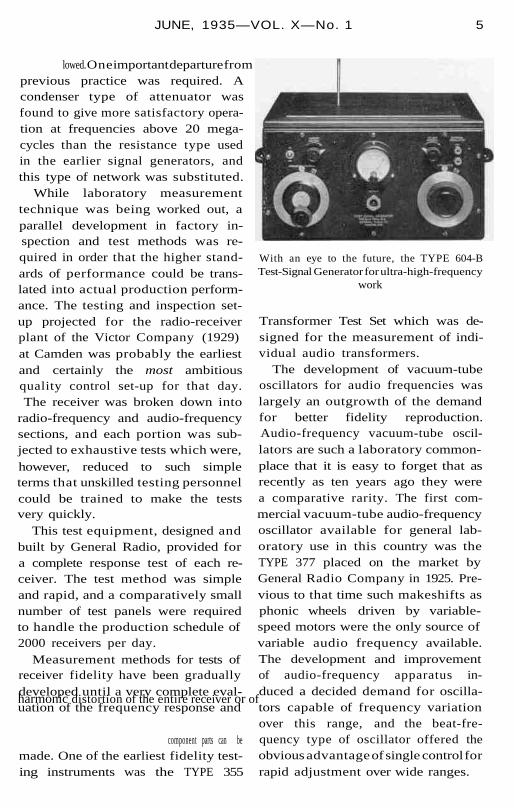
lowed. One important departure fromprevious practice was required. Acondenser type of attenuator wasfound to give more satisfactory opera-tion at frequencies above 20 mega-cycles than the resistance type usedin the earlier signal generators, andthis type of network was substituted.
While laboratory measurementtechnique was being worked out, aparallel development in factory in-spection and test methods was re-quired in order that the higher stand-ards of performance could be trans-lated into actual production perform-ance. The testing and inspection set-up projected for the radio-receiverplant of the Victor Company (1929)at Camden was probably the earliestand certainly the most ambitiousquality control set-up for that day.The receiver was broken down into
radio-frequency and audio-frequencysections, and each portion was sub-jected to exhaustive tests which were,however, reduced to such simpleterms that unskilled testing personnelcould be trained to make the testsvery quickly.
This test equipment, designed andbuilt by General Radio, provided fora complete response test of each re-ceiver. The test method was simpleand rapid, and a comparatively smallnumber of test panels were requiredto handle the production schedule of2000 receivers per day.
Measurement methods for tests ofreceiver fidelity have been graduallydeveloped until a very complete eval-uation of the frequency response andharmonic distortion of the entire receiver or of
component parts can bemade. One of the earliest fidelity test-ing instruments was the TYPE 355
With an eye to the future, the TYPE 604-BTest-Signal Generator for ultra-high-frequency
work
Transformer Test Set which was de-signed for the measurement of indi-vidual audio transformers.
The development of vacuum-tubeoscillators for audio frequencies waslargely an outgrowth of the demandfor better fidelity reproduction.Audio-frequency vacuum-tube oscil-lators are such a laboratory common-place that it is easy to forget that asrecently as ten years ago they werea comparative rarity. The first com-mercial vacuum-tube audio-frequencyoscillator available for general lab-oratory use in this country was theTYPE 377 placed on the market byGeneral Radio Company in 1925. Pre-vious to that time such makeshifts asphonic wheels driven by variable-speed motors were the only source ofvariable audio frequency available.The development and improvementof audio-frequency apparatus in-duced a decided demand for oscilla-tors capable of frequency variationover this range, and the beat-fre-quency type of oscillator offered theobvious advantage of single control forrapid adjustment over wide ranges.

6 THE GENERAL RADIO EXPERIMENTER
The Type 713 Beat-Frequency Os-cillator just being announced is theculmination of a series of beat oscil-lators reaching back about eightyears. It is remarkable in the highvoltage and power output for this typeof oscillator, as well as for an unusual-ly fine waveform.
Fidelity and gain measurements ledinto many ramifications of apparatus.An interest in wave distortion—thatis, harmonic generation—in tubes andamplifiers has been a comparativelyrecent development. The cathode-rayoscillograph has been of great valuein rough measurements of this kind,but the Type 636 Wave Analyzer pro-duces a complete and accurate analy-sis of a distorted waveform, showingharmonics of magnitude far too smallto be detected in an oscillogram. This
The TYPE 377-B Low-Frequency Oscillatorgenerates audio and carrier frequencies up to
seventy kilocycles
instrument is probably the mostspecialized and highly developed inour line, and well serves as a tangiblemonument to our twenty years.
A perfect combination for audio-frequency measurements. On the left the newest Beat-frequency oscillator. General Radio TYPE 713-A, and on the right the TYPE 636-A Wave Analyzer
for harmonic analysis

JUNE, 1935—VOL. X—No. 1 7
ALTERNATING-CURRENT BRIDGES
THE development of bridge circuitsconstitutes a particularly good il-
lustration of the working out of theobjectives of the General Radio Com-pany. At the time of the founding ofthe Company the fundamental bridgecircuits were well known. The Wheat-stone Bridge was, in fact, first de-scribed in 1833. Standardized com-mercial bridges were, however, notextensively available at low prices. Infact, there seems to have been noAmerican manufacturer of alternat-ing-current bridges at that period, al-though English and Continental firmswere listing them.
The purpose of the General RadioCompany was to make commerciallyavailable established types of measuring
equipment which would bemanufactured on a standardized basisapplying, so far as possible, mass-pro-duction principles in this field. Thepurpose was to place the burden ofthought and planning on the designerand manufacturer, leaving the user ofthe equipment free to devote his fullattention to the main objectives of hisinvestigation undistracted by the ne-cessity of coddling his equipment, andto remove accurate laboratory andshop measuring equipment from theluxury class.
Marked emphasis is lent to the con-trast between this conception and thethen current view by the practice of aleading English manufacturer of lab-oratory equipment. As a deliberatepolicy, parts and instruments weremade non-standard, screws were separately
cut on a screw-machine withdiffering threads so that if any partwere lost or broken the instrument
would have to be sent back to themanufacturer for hand-fitting of newparts.
The bridges of the period weremostly of the once familiar type, dis-playing panels studded with large,highly polished brass blocks, connec-tions being made by the insertion oftapered plugs between the blocks, al-though the dial-decade type of bridgehad been introduced and was avail-
Even decade-resistance boxes improve. Thelatest TYPE 602 right is completely shielded,has better switches, contacts, terminals, wir-ing, and card construction than the older
TYPE 102 left
able in a direct-current bridge (thewell-known TYPE K Test Set) manu-factured by Leeds and Northrup.
Most of the bridges offered formeasurement of inductors and capac-itors operated on pulsating ratherthan alternating current. A basic re-quirement for a satisfactory bridge tooperate at 1000 cycles or at higheraudio frequencies is a type of resis-tance which can be used in the ratioarms without introducing frequencyerrors. The earlier alternating-currentbridges were of the slide-wire type us-ing a straight resistance wire with aslider as the ratio arms of the bridge.The Ayrton-Perry type of winding,which is nonreactive at audio frequen-

THE GENERAL RADIO EXPERIMENTER8
The TYPE 193 Decade Bridge, an intermediatestage in the extension of the decade bridge
to alternating-current measurements
cies, was first introduced in GeneralRadio resistance boxes in our familiarTYPE 102. With this type of windingit was possible to build up non-reactive resistors of large values,greatly extending the possible rangeand flexibility of bridges over theslide-wire type. This was very quicklyfollowed by an impedance bridgewhich consisted of ratio arms and apower-factor arm with provision forconnecting unknown and standards.A redesign of this bridge became theTYPE 193 with which many commer-cial and educational laboratories
The T Y P E 293 Universa l Bridge has a greaterflexibility of arrangement of the arms and the
enclosed-contact construction
were equipped. It gave way a fewyears ago to the TYPE 293, a bridgeof similar general characteristics butso designed that all impedanceswould terminate on the panel so thatall types of standard bridge circuits.could be set up.
Measurement of power factor ofinsulating materials was another ofthe problems which was approachedin the early years of the Company.The TYPE 216 Bridge was evolved forthis purpose and has been the stand-ard method of precise power-factordeterminations for many years.
The refinement of decade bridges leads to specialized impedance bridges of greater usefulnessin smaller fields, s uch as the Type 216 Capacity Bridge left, and the Type 650-A Impedance
Bridge right
JUNE, 1935 - VOL. X-No. 1 9
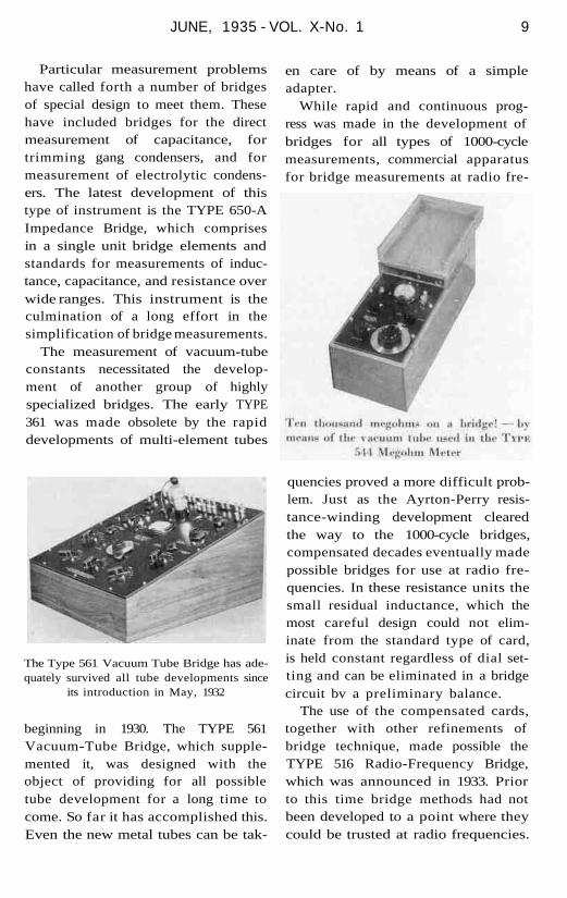
Particular measurement problemshave called forth a number of bridgesof special design to meet them. Thesehave included bridges for the directmeasurement of capacitance, fortrimming gang condensers, and formeasurement of electrolytic condens-ers. The latest development of thistype of instrument is the TYPE 650-AImpedance Bridge, which comprisesin a single unit bridge elements andstandards for measurements of induc-tance, capacitance, and resistance overwide ranges. This instrument is theculmination of a long effort in thesimplification of bridge measurements.
The measurement of vacuum-tubeconstants necessitated the develop-ment of another group of highlyspecialized bridges. The early TYPE361 was made obsolete by the rapiddevelopments of multi-element tubes
en care of by means of a simpleadapter.
While rapid and continuous prog-ress was made in the development ofbridges for all types of 1000-cyclemeasurements, commercial apparatusfor bridge measurements at radio fre-
The Type 561 Vacuum Tube Bridge has ade-quately survived all tube developments since
its introduction in May, 1932
beginning in 1930. The TYPE 561Vacuum-Tube Bridge, which supple-mented it, was designed with theobject of providing for all possibletube development for a long time tocome. So far it has accomplished this.Even the new metal tubes can be tak-
quencies proved a more difficult prob-lem. Just as the Ayrton-Perry resis-tance-winding development clearedthe way to the 1000-cycle bridges,compensated decades eventually madepossible bridges for use at radio fre-quencies. In these resistance units thesmall residual inductance, which themost careful design could not elim-inate from the standard type of card,is held constant regardless of dial set-ting and can be eliminated in a bridgecircuit bv a preliminary balance.
The use of the compensated cards,together with other refinements ofbridge technique, made possible theTYPE 516 Radio-Frequency Bridge,which was announced in 1933. Priorto this time bridge methods had notbeen developed to a point where theycould be trusted at radio frequencies.

10 THE GENERAL RADIO EXPERIMENTER
coils measured at audio frequencies.Although the commercial develop-
ments of bridge circuits brieflysketched here have made availablean extensive line of reliable, easilyoperated equipment, the increasing-ly severe requirements of industrialmeasurements indicate that bridge de-velopment must be continuously car-ried forward, and it is, in fact, at thistime one of our most active programs.
The TYPE 516-C Radio-Frequency Bridgemeasures impedances directly at frequencies
up to 5 megacycles
Substitution and voltammeter meth-ods had persisted in this high-fre-quency region long after they hadbeen abandoned elsewhere.
The compensated resistor also madepossible the construction of a bridge(TYPE 667) for another particularlydifficult problem, the measurement ofa small inductance associated with acomparatively large resistance. Thisis characteristic of radio-frequency
The latest development in measuring smallinductances, the TYPE 667-A Inductance
Bridge, June, 1935
FREQUENCY MEASURING INSTRUMENTS
I N 1915, the standard frequency-measuring device was the tuned-
circuit wavemeter. The parallel-wiresystems used by Hertz, Marconi,Lecher, and others had, with the in-troduction of longer and longerwavelengths, been displaced by vari-ous types of coil and condenser com-binations, either or both elements ofwhich were adjustable. General Radiohas brought out over twenty differentwavemeter models, of which a fewmay be mentioned as of interest here.
One of the earliest was the TYPE105, brought out late in 1917, whichincluded plug-in coils, buzzer, crystaldetector, and telephones. Provisionalso was made for the use of a thermo-couple and galvanometer, or a neontube as the resonance indicator.
The Kolster Decremeter was one ofthe first commercial instrumentsfitted with a variable condenser hav-ing specially shaped plates to obtaina desired relationship between fre-quency (wavelength) and scale read-

JUNE, 1935-VOL.X-No.l 11
Still modern after fifteen years, the currentdemand for the TYPE 224 Precision Wave-meter pays tribute to the excellence of the
original design
ing. With the widespread use of con-tinuous wave transmitters, the de-cremeter has fallen into disuse.
The TYPE 224 Wavemeter was oneof the first commercial models (about1920) incorporating the features ofprecision variable condenser con-struction and worm drive. The worm-drive condenser had a scale of 2500readable divisions, an increase of tentimes, or more, over contemporarymodels.
The TYPE 574 Direct-ReadingWavemeter incorporated the novelarrangement of using plug-in coils,each carrying its direct-reading cali-bration engraved on the coil form.The possibility of making an error inreading is greatly reduced, since thereis but one scale in place of the usualarrangement of several in direct-reading multi-range instruments.
Practically all of these earlier in-struments were calibrated by refer-ence to some other instrument of the
same or similar type, whose calibra-tion had been in turn determined byreference to some other instrument,
and so on, ad infinitum. What withthe defects of design, errors arisingfrom shipment, aging, temperaturechanges, and so forth, it is not surpris-ing that there was a disappointinglack of agreement among various in-struments.
Early in the 1920's standard fre-quencies were transmitted by the U. S.Bureau of Standards based on theirstandard wavemeter. Such transmis-sions had the great advantage ofbringing the frequency standard, soto speak, into the laboratory of theuser, and, further, brought a consid-erable improvement in the uniform-ity of results, since workers in manylocations were able to make use of asingle standard.
It was only when the standardwavemeter was replaced by oscillatorsof relatively high frequency stability,with means for determining the fre-quency directly in terms of time, thatthe precision of frequency measure-ments began to make rapid progresstoward the high accuracies now pos-sible.
The TYPE 574 Direct-Reading Wavemetercombines accuracy with rapidity of setting
Thus the use of piezo-electricquartz crystals for the frequency sta-bilization of radio-frequency oscil-lators in the early 1920's marks animportant milestone in frequencymeasurements.
The first commercial piezo-electric

12 THE GENERAL RADIO EXPERIMENTER
oscillator appeared in 1924, known asthe TYPE 275. This instrument servedas either a laboratory standard or asa frequency monitor. In the lattercapacity it gave satisfactory perform-ance down through the days of the500-cycle tolerance in broadcasting.In this early work General RadioCompany furnished the first quartzcrystals to be used in controlling thefrequency of a broadcast station(WEAF, 1923) and the first crystalsused in commercial radio transmitters(RCA, 1923).
With demand for higher accura-cies, the shortcomings of the earlypiezo-electric oscillators were over-come by progressive improvements
The early Type 275 Piezo-Electric Oscillatormade no provision for temperature control of
the Quartz Plate
in the cutting of the quartz plates, inthe mountings and circuits, and intemperature control. As a result theaccuracy was improved from 0.l% to0.001%, and simultaneously the con-venient improvement of a-c operationwas included.
Early experimental determinationsof frequency in terms of time forecast
The TYPE 411 Synchronous Motor integratedapplied frequencies to give an absolute evalua-
tion in terms of standard time
the development of the primarystandard of frequency. In 1859 Fed-derson used a rotating mirror tophotograph a spark discharge andprove the oscillatory character of thedischarge. By timing the rotation ofthe mirror, in terms of a tuning fork,Pierce was able to obtain a measure-of the frequency of the spark oscilla-tions, in 1915. By photographing theoscillations of an oscillator operatingat a submultiple of the frequency ofa quartz crystal oscillator and super-imposing a timing record of pulsesobtained from a chronometer. Pierceobtained a measure of the frequencyin terms of time (about 1923) bycounting the number of cycles perunit time and multiplying by thenumber of the harmonic of the oscil-lator controlled by the crystal.
In 1919 Abraham and Block de-scribed the "multivibrator," a typeof relaxation oscillator having an out-put "rich in harmonics." This devicewas used to multiply frequencies byharmonic methods to obtain low andmedium radio frequencies from anaudio-frequency standard oscillator,such as a tuning fork. A little later,Dye incorporated such a standardiz-

JUNE, 1935—VOL. X—No. 1 13
ing equipment in a heterodyne fre-quency meter. Later it was found*that the multivibrator lent itselfparticularly well to the division offrequencies. That is, on the introduc-tion of a voltage from a piezo-electricoscillator, the frequency of the multi-vibrator could be stabilized by thepiezo-electric oscillator, even thoughthe frequency of the piezo-electricoscillator was several times higherthan the fundamental frequency ofthe multivibrator.
The TYPE 411 Synchronous-MotorClock was brought out in 1926 andan early model was used by Marrison*in his work with the precisiontuning fork standard at the BellLaboratories.
The elements of the primary fre-quency standard were by now athand: The piezo-electric oscillator ofhigh frequency stability as the stand-ard; the multivibrator as a frequencydivider, to bring the radio frequencystandard down to frequencies suit-able for use in synchronous motors ofthe impulse type, and the synchro-nous-motor clock for counting thenumber of oscillations executed bythe piezo-electric oscillator in a giventime interval.
The first commercial primary fre-quency standard was the CLASS C-21-Hbrought out by General Radio Com-pany in 1928. This laboratory fre-quency standard had an accuracy ofone part in a million (0.0001 percent), furnished hundreds of stand-ard frequencies throughout the radio-frequency spectrum for measurement
* "Universal Frequency Standard iza t ion from a Sinple-Frequenry Source," J. K. Clapp, Journal of the OpticalSociety of A m e r i c a and Review of Scient if ic Instruments,July, 1927.
* "Precision Determination of Frequency," J. W. Horton and W.A. Marrison, Proc. I . R . E . , February, 1928.
The final development, the Primary Standardof Frequency, accurate to within 5 parts in10 million, left, and its auxiliary frequency-
measuring equipment, right
use, and provided means for compar-ing the time of the crystal controlledclock with time signals to within 0.01second. Later models yield an ac-curacy of a few parts in ten million.
Interpolation instruments for meas-uring frequencies in terms of har-monics supplied by the primarystandard have been developed, bymeans of which frequencies from afew kilocycles to several megacyclescan be measured with an accuracy ofa few parts in one million.
Equipment of this type has beenwidely used in government and com-mercial services all over the world.Interesting applications, in additionto the normal uses for frequencymeasurements, have been in the meas-urement of bullet velocities, themeasurement of velocity of light, andas precise standards of time.

14 THE GENERAL RADIO EXPERIMENTER
ELECTRICAL MEASUREMENTS IN THE RADIOBROADCASTING STATION
IT is significant that the two portionsof the radio industry which are
most important from the economicstandpoint (radio broadcasting andradio receiver manufacture) havebeen responsible for a major portionof the technical advances and instru-ment design in communication-fre-quency measurements during the lastten years. The radio broadcasting in-dustry, in particular, affords an out-standing example of the way in whichtechnical developments are condi-tioned and even forced by economicfactors.
The operation of a modern radiobroadcasting station involves, as amatter of routine, the measurement ofmany electrical quantities such asaudio-frequency and carrier powerlevels, frequency, modulation level,noise level, and harmonic distortion,as well as the measurement of alloperating voltages and currents invacuum tube circuits. The design ofequipment for broadcasting stationuse has tended always toward auto-matic or direct-reading instrumentswhich require a minimum of atten-tion on the part of the operator.
The two major assets of a radiobroadcasting station are its operatinglicense, which is granted by govern-mental authority, and its coverage,that is, the number of listeners whichit can reach. To retain the former andto increase the latter are the twofactors which mean the most, econom-ically, to the station.
The granting of an operating li-
cense to the broadcasting station iscontingent upon the observance ofcertain rules and regulations govern-ing frequency, output level, qualityof output, and operating procedure,specified (in this country) by theFederal Communications Commis-sion. Operating within these specifiedlimits, particularly at a specifiedcarrier power level, the station whichcan operate with the highest percent-age modulation, the minimum distor-tion, and the best radiating system isthe one which, in terms of monetaryreturn, makes the best success as agoing concern.
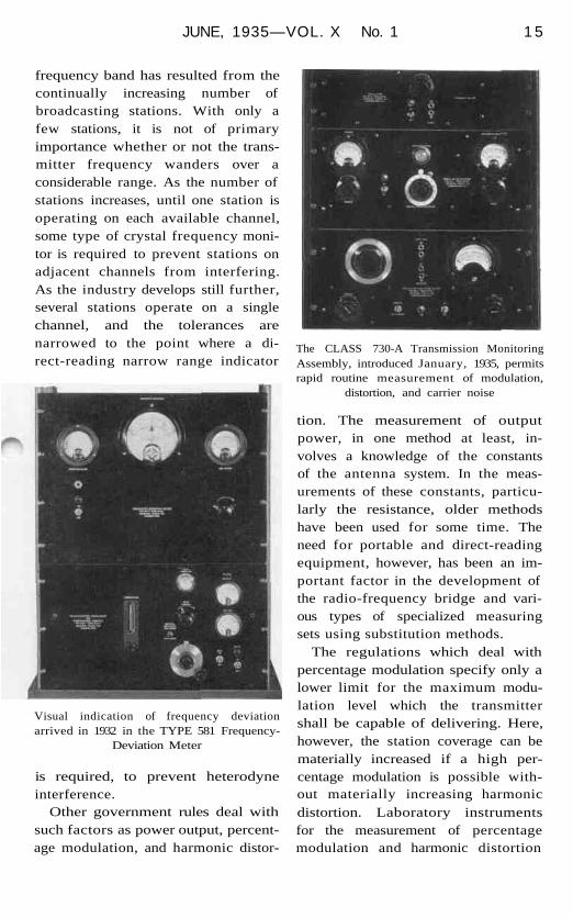
One of the primary rules prescribedby the Federal Communications Com-mission deals with the maintenanceof the operating frequency of thetransmitter within certain specifiedlimits. These regulations have beenresponsible for the development ofthe present technique of frequencymonitoring in broadcasting stations,culminating in the visual-type, direct-reading, frequency monitor. Theconstant narrowing of frequency tol-erances in the standard broadcast-
TYPE 375 Station Piezo-Electric Oscillator,the broadcast-station frequency monitor of
1926
JUNE, 1935—VOL. X No. 1 1 5
frequency band has resulted from thecontinually increasing number ofbroadcasting stations. With only afew stations, it is not of primaryimportance whether or not the trans-mitter frequency wanders over aconsiderable range. As the number ofstations increases, until one station isoperating on each available channel,some type of crystal frequency moni-tor is required to prevent stations onadjacent channels from interfering.As the industry develops still further,several stations operate on a singlechannel, and the tolerances arenarrowed to the point where a di-rect-reading narrow range indicator
Visual indication of frequency deviationarrived in 1932 in the TYPE 581 Frequency-
Deviation Meter
is required, to prevent heterodyneinterference.
Other government rules deal withsuch factors as power output, percent-age modulation, and harmonic distor-
The CLASS 730-A Transmission MonitoringAssembly, introduced January, 1935, permitsrapid routine measurement of modulation,
distortion, and carrier noise
tion. The measurement of outputpower, in one method at least, in-volves a knowledge of the constantsof the antenna system. In the meas-urements of these constants, particu-larly the resistance, older methodshave been used for some time. Theneed for portable and direct-readingequipment, however, has been an im-portant factor in the development ofthe radio-frequency bridge and vari-ous types of specialized measuringsets using substitution methods.
The regulations which deal withpercentage modulation specify only alower limit for the maximum modu-lation level which the transmittershall be capable of delivering. Here,however, the station coverage can bematerially increased if a high per-centage modulation is possible with-out materially increasing harmonicdistortion. Laboratory instrumentsfor the measurement of percentagemodulation and harmonic distortion

16 THE GENERAL RADIO EXPERIMENTER
were developed and used in mostbroadcasting stations. With the in-creasing demand for high-qualitytransmission, however, automatic anddirect-reading equipment became nec-essary, and instruments of the typeshown on page 15 represent the lat-est developments in this particularfield. With equipment currently avail-able, it is possible to make a completecheck on the quality of the output ofa radio transmitter, consisting ofmeasurements of modulation level,harmonic distortion, and noise level,in a few minutes. In addition, the out-
The Type 457 Modulation Meter gives labo-ratory measurement of percentage modulation
on positive or negative peaks
put level can be continuously moni-tored, giving the operator, at a glance,a complete check on the operation ofhis transmitter at all times.
Instruments for the measurementof the quality of the output of a radiotransmitter, while showing the oper-ating condition, must, of course, besupplemented by adjustments andmeasurements in the various portionsof the transmitter itself in order tolocate and eliminate sources of im-proper operation. That section of thetransmitter which has received themost attention is the audio-frequency
The Type 536 Distortion-F actor Meter mea-sures the 400-cycle distortion in an audio-
frequency system
portion, consisting of microphonepickups and amplifiers, speech inputequipment, and speech amplifiers.
To minimize distortion in theaudio-frequency system, it is neces-sary that the audio-frequency powerlevel be continuously monitored atvarious points in the system. The de-mand for moderately-priced and com-pact direct-reading instruments wasan important factor in the develop-ment of the copper-oxide-rectifiertype of power-level indicator whichis now almost universally used in thebroadcasting and sound motion pic-ture industries.
Since the beginning of commercialradio broadcasting. General Radiohas supplied a large portion of themeasuring tools of the broadcast sta-tion engineer. One or more General
The TYPE 586 Power-Level Indicator programmonitors the audio-frequency level fed to the
transmitter

JUNE, 1935 - VOL. X-No. 1 17
Radio instruments, ranging from theinexpensive microphone mixer con-trol to the direct-reading transmissionmonitoring equipment, are in use to-day in practically all the broadcastingstations of the United States. Many ofthese instruments have been distinctadvances in the technique of a-c elec-
trical measurements, but it is to thebroadcasting industry, as the origina-tor of the demand for the applicationof the advantages of direct-reading in-struments to precision methods ofmeasurement, that the radio art owesmuch of its progress in the pastdecade.
WHO'S WHO
WHY all this review of the art ofelectrical measurements in the
field of audio and radio frequencies?The purpose is to point out that, newas this field is, the General RadioCompany is one of the oldest com-panies in it. On June fourteenth wecomplete the second decade of ourexistence.
Five years ago on the occasion of' the celebration of our fifteenth birth-
day we devoted an issue of THEGENERAL RADIO EXPERIMENTER to de-scribing the history of the Companyand to portraying by word and by pic-ture some of the personnel who makeup the organization. When recentlywe contemplated repeating this pro-cedure, our printer looked over thepictures of our staff as shown in thatissue of five years ago and remarked,"The depression certainly has left itsmark on some of you!" So great wasthe shock to those of us who have beenpriding ourselves on retaining ouryouthfulness that we decided it mightbe better not to let our readers seehow old and decrepit we had become.
Consequently, the 1935 edition of"Who's Who at General Radio" fol-
lows the traditional form of such pub-lications and contains no pictures.Because we are fundamentally an en-
gineering organization, and becausethe EXPERIMENTER readers are largelyengineers, our word portraits will belimited principally to members ofthe engineering group.
We are most happy to state that allof those listed in the issue of five yearsago are still living and, with the ex-ception of J. W. Horton, are still withus. Mr. Horton has given up hisexecutive work to devote his time en-tirely to research and is now a researchassociate at the Massachusetts Insti-tute of Technology, doing a mostpromising piece of work in the fieldof bio-physics, on which problem thisCompany is co-operating.
We are also glad to say that KnutA. Johnson, the first employee of theCompany, is still with us.
Although the Company has nodefinite unemployment plan, it haslong had such a problem in mind inthe maintenance of reserves, whichhave made it possible during the pastfive years to keep the entire organiza-tion together. Only for a brief periodof time did the employment hoursdrop to 60% of normal, and, exceptfor a few workers taken on in 1929,no employee was dropped because ofdeclining business.
The officers remain unchanged.

1 8 THE GENERAL RADIO EXPERIMENTER
Henry S. Shaw continues as Chairmanof the Board of Directors. Althoughhe does not take part in the activedetails of management, Mr. Shaw isat the Company offices several dayseach week and, in addition to main-taining a keen interest in apparatusdevelopment, particularly in the fieldof ultra-high frequencies, has throughhis personal generosity made pos-sible the establishment of a fundavailable for the general welfare ofemployees and their families.
The General Radio Company owesits very existence to its President,Melville Eastham. It was he whofounded it, and it is he who has ledit through the varied transitions ofthe past twenty years. No more aptdescription of his duties can be foundthan by repeating what was writtenof him five years ago: "His activities. . . , however, are not properly de-scribed by his title, for he is rarelyfound at his presidential desk. Hisinterests are almost exclusively in en-gineering work, and he may usuallybe found in his research laboratory,except during the summer, when hetakes a long vacation, generally on thePacific Coast or in Europe." That theremarks of the printer may not betaken too seriously, let it be recordedhere that both the Chairman of theBoard and the President have just ar-rived at that ripe old age of half acentury.
In charge of all manufacturing andplant operations is Vice-PresidentE. H. Locke. On him is placed allblame when deliveries are slow, andhis good work is too easily forgottenwhen the Commercial Departmentfinds itself overstocked. Seventeen
years of association with the Com-pany, fifteen of which have been incharge of manufacturing, have, how-ever, done much to reconcile him tothe small amount of help and of ap-preciation he may ever expect fromthose responsible for customer con-tacts.
Like Messrs. Shaw and Locke, H. B.Richmond, the Company's Treasurer,joined Mr. Eastham when the yearsof the Company were still beingcounted on the fingers of one hand.It seems to be a habit of officers of theGeneral Radio Company, regardlessof title, to be closely associated withengineering, thus Mr. Richmond, inaddition to his usual duties as Treas-urer, watches over those phases ofengineering pertaining directly tocustomer relationships, which, in ourorganization, is just a long way orsaying sales.
Before apparatus can be manufac-tured it must be designed. Afteragreement among a conference group,at which specifications and other im-portant limiting factors, includingprobable price, are agreed upon, thedevelopment and actual design arecarried out by an engineering groupknown as Development Engineering.This group is headed by Mr. East-ham, assisted by Eduard Karplus,who received his Dipl. Eng. fromthe Technische Hochschule, at Vien-na. The work carried on by the vari-ous engineers in this group is toovaried to attempt to give any detailsof their specific activities. It perhapsis sufficient to state that most of thenew items listed in our newly pub-lished Catalog H are the product ofthe engineers in this group, which
JUNE, 1935-VOL.X—No.1 19
includes: L. B. Arguimbau, S.B., Har-vard; A. G. Bousquet, B.E.E., Tufts;J. D. Crawford, S.B., MassachusettsInstitute of Technology; H. W. Lam-son, S.B., Massachusetts Institute ofTechnology, A.M., Harvard; andW. N. Tuttle, Ph.D.. Harvard.
Oftentimes a standard item is theresult of work which originated inconnection with some customer prob-lem. For this reason a considerablenumber of our instruments have beendeveloped by members of a secondengineering group, known as the Gen-eral Engineering Department. Whilethis group is under the general direc-tion of Mr. Richmond, its administra-tion is actively carried out by C. T.Burke, S.M., Massachusetts Instituteof Technology, whose title is thatof Engineering Manager. As manyEXPERIMENTER readers know mem-bers of this group through personalcontact or through correspondence, itseems appropriate to note the par-ticular functions of the various en-gineers within this group.
A. E. Thiessen, B.E., Johns Hop-kins, is the engineer in charge ofGovernment activities and, in gen-eral, quantity special-problem items.He, too, has supervised the develop-ment of some items that have foundtheir way into the catalog.
R. F. Field, A.M., Brown and Har-vard, is familiar to many EXPERI-MENTER readers for his work in bridgemeasurements and allied subjects.Nearly all the new bridges and asso-ciated equipment appearing in ourrecent catalog have been developedunder Mr. Field's direction.
No one at General Radio can thinkof frequency standardization without
thinking of it in terms of J. K. Clapp,S.M., Massachusetts Institute of Tech-nology. A very considerable numberof the broadcast stations in the UnitedStates have frequency-monitoringequipment developed by him, and itis the boast of the Company that thesun never sets on Mr. Clapp's pri-mary-frequency standards, so world-wide is their distribution.
How much is it going to cost? Thatanswer usually comes from P. K. McElroy, A.M., Harvard. Nearly allitems of special manufacture andchanges from standard design havetheir costs estimated by Mr. McElroy.To him also falls the lot of directingthe final engineering design of muchof Mr. Thiessen's special contractwork.
If it must be made in a hurry, itgoes to H. S. Wilkins, S.B., Massachu-setts Institute of Technology, and hismodel shop. Not only does Mr. Wil-kins handle individual customer prob-lems, but nearly all our own firstmodels are produced in his group.
Who publishes the EXPERIMENTER?C. E. Worthen, S.B., MassachusettsInstitute of Technology, and he doesa whole lot of other things, too, thatmake it easier for General Radio cus-tomers to know what we make and,after a purchase, how to make the ap-paratus work.
If your name is not correctly listedin our mailing files, blame J. M. Clay-ton, of Cornell. If you do not like ouradvertisements, tell Mr. Clayton, be-cause he is responsible for the prep-aration of most of them as well.
Joining our staff only a year ago isFrank L. Tucker, B.S., University ofTexas; M.B.A., Harvard Business

20 THE GENERAL RADIO EXPERIMENTER
School. Mr. Tucker devotes his timeto a statistical analysis of all costs,devoting particular attention to thosepertaining to all forms of engineeringin order that they may be properlyallocated to their respective instru-ments.
Jnst a year ago it seemed advisableto have a New York engineering officeto assist our metropolitan customersin the solution of technical problemsinvolving our equipment. For this im-portant post M. T. Smith, S.M.,Massachusetts Institute of Technol-ogy, was selected, and he is alreadyfamiliar to many General Radiofriends in the New York district.
Others in the General EngineeringDepartment who are devoting theirtime to helping customers in their en-gineering problems and who also arewatching out for methods of improv-ing our product are H. H. Scott, S.M.,Massachusetts Institute of Technol-ogy; W. G. Webster, S.M., Massachu-setts Institute of Technology; andF. Ireland, A.B., Harvard.
Also under the nominal supervisionof Mr. Richmond but actively andably administered by its chief, C. E.Hills, Jr., B.E.E., Northeastern, withtitle of Commercial Manager, is theCommercial Department. From thecustomers' viewpoint this is one of ourmost important groups, because heretakes place the handling of all ordersand the accounting associated withthem. Directly handling the orders isH. P. Hokanson, and when exchangeor servicing is necessary this workcomes to the attention of H. H. Dawes.
The accuracy of the accounts is theresponsibility of A. W. Lufkin.
This Company has long takengreat pride in the packing of its ap-paratus for shipment. This work hasbeen ably directed for more thanthree quarters of the Company's exist-ence by F. W. Beck.
Associated with Mr. Locke on pro-duction problems is a competent staff,some of whom, too, have likewise re-ceived an engineering training. Thenature of their work is, however, aointerrelated that it will not be de-tailed here.
Labor turnover continues to bevery small. In spite of the fact thatduring the past year there was an in-crease in employment of 14% fromthe average level of the precedingfour years, 81% of the entire organi-zation have been with the Companyover five years. In fact, 41 % have overten years of service to their credit.
The Company has been operatingunder the Scientific Apparatus Mak-ers' Code, but its own conditions re-garding hours and rates of pay hadlong anticipated code requirements.In fact, a five-day week with full payon holidays, and with time-and-one-half pay for overtime, has been inforce for nearly sixteen years. Everyemployee who has been with the Com-pany one year receives two weeks'vacation with pay each summer. Freemedical consulting service and aid inthe event of unusual illness are alsoprovided. The employees have theirown Mutual Benefit Association andoperate their own Credit Union.
GENERAL RADIO COMPANY30 State Street - Cambridge A, Massachusetts