The feasibility of DVB-T on-channel repeaters for … repeaters for coverage repair on Channel 60...
42
2109/OCR/R/3.0 5 August 2009 The feasibility of DVB-T on-channel repeaters for coverage repair on Channel 60 Ofcom
Transcript of The feasibility of DVB-T on-channel repeaters for … repeaters for coverage repair on Channel 60...

2109/OCR/R/3.0
5 August 2009
The feasibility of DVB-T on-channel repeaters for
coverage repair on Channel 60
Ofcom


Ægis Systems Limited Feasibility of on-channel repeaters for DTT
2109/OCR/R/3.0 i
Table of Contents
1 INTRODUCTION ................................................................................. 1
2 DVB-T AND ADJACENT-CHANNEL INTERFERENCE ............................... 2
2.1 UK coverage criteria .......................................................................................... 2
2.2 Protection ratio for non-DTT interferers .......................................................... 2
2.2.1 UMTS interference .......................................................................................... 3
2.2.2 WiMax interference ......................................................................................... 4
2.2.3 Conclusion....................................................................................................... 5
2.3 Overload effects ................................................................................................. 5
2.4 Practical Impact of ‘hole-punching’ ................................................................. 7
2.4.1 Whitehawk Hill case study .............................................................................. 8
3 ON-CHANNEL REPEATERS ................................................................. 10
3.1 Introduction ........................................................................................................ 10
3.2 Digital OCR technology ..................................................................................... 11
3.3 Specifications and commercial hardware ....................................................... 14
3.3.1 BBC R & D design ........................................................................................... 14
3.3.2 „PLUTO‟ project ............................................................................................... 14
3.3.3 Rohde & Schwarz XLx 8000 ........................................................................... 15
3.3.4 Harris „ATOM‟ TVU-D 665 ............................................................................... 15
3.3.5 Teamcast GFX-0300 ....................................................................................... 16
3.3.6 Tredess 85100x series .................................................................................... 17
3.3.7 Specification comparison ................................................................................ 17
3.3.8 Cost ................................................................................................................. 18
4 PRACTICAL IMPLEMENTATION ISSUES ................................................. 19
4.1 Power levels at repeater input .......................................................................... 19
4.2 Polarisation issues ............................................................................................ 20
4.3 Combining of DTT signals ................................................................................. 20
4.4 Installation of receiving aerials ......................................................................... 21
4.5 Knock-on impact to Channel 59 ....................................................................... 21

Ægis Systems Limited Feasibility of on-channel repeaters for DTT
ii 2109/OCR/R/3.0
4.6 DVB-T2 ................................................................................................................ 22
5 EXISTING STUDIES ............................................................................ 23
5.1 DAB repeaters .................................................................................................... 23
5.2 Operational systems .......................................................................................... 23
5.3 CEPT SE42 .......................................................................................................... 24
5.4 Discussion .......................................................................................................... 24
6 FIELD TRIALS ................................................................................... 25
6.1 Small-scale trial proposal .................................................................................. 26
7 CONCLUSIONS .................................................................................. 26
7.1 Recommendations ............................................................................................. 27
A ANNEX A: REFERENCES ................................................................... 29
B ANNEX B: GLOSSARY ....................................................................... 30
C ANNEX C: WORK ON ADJACENT BAND COMPATIBILITY WITHIN THE
CEPT ELECTRONIC COMMUNICATIONS COMMITTEE (ECC) ................. 31

Ægis Systems Limited Feasibility of on-channel repeaters for DTT
2109/OCR/R/3.0 1
1 INTRODUCTION
The current UK plan for post-Digital Switchover (DSO) terrestrial television makes
use of two sub-bands of the UHF spectrum currently used for digital and analogue
television broadcasting. These bands cover channels 21-30 (470-550 MHz) and
41-62 (630-806 MHz).
As momentum has grown across Europe for the harmonisation of frequencies above
790 MHz for cellular mobile use, it is looking increasingly likely that channels 61 and
62 will not be used for Digital terrestrial TV (DTT) following switchover.
Under tentative CEPT bandplans, the spectrum immediately above 790 MHz would
be used by cellular base station transmitters (hereafter referred to generically as
Electronic Communications Network, or ECN transmitters). This raises the
possibility that domestic DTT reception on Channel 60 might suffer interference from
nearby base stations that give rise to such high levels of power in the channel
adjacent to the wanted DTT signal that the TV receiver fails to operate. This
scenario is often referred to as „hole punching‟.
The severity of such interference can be reduced if a guard band is introduced
between the upper edge of the DTT channel and the lower edge of the ECN
channel; although this approach could be considered to be wasteful of spectrum, it
has the merit of operational simplicity. Whatever guard band is chosen, however,
the risk of interference can never be reduced to zero.
An alternative, or complementary, approach to the problem would be to co-locate a
small DTT „booster‟ transmitter at any interfering ECN base station. This would
increase the available DTT signal in the area to an extent sufficient to protect if from
interference. As the two transmissions would be from the same location, their
strength would, broadly speaking1, vary in unison across the coverage area, thus
preserving the required protection ratio.
Normal UK practice is to operate DTT relay stations on different channels to those
of the parent transmitter (a multi-frequency network, or MFN). In the present
context, this would have the disadvantages that service planners would need to find
a (potentially large) number of new channels on which such fillers could operate
and, perhaps more seriously, viewers would need to re-scan their receivers if they
find their services interfered with.
An apparently attractive option, therefore, is to operate such fillers on the same
channel (i.e. ch.60) as the interfered-with service. This is possible with DTT, as the
COFDM signal is resistant to multipath signals (within limits2), allowing the use of
multiple transmitters as a „single frequency network‟, or SFN.
1 This will not apply to the „fast‟ or Rayleigh fading that is characteristic of multipath rich channels
2 The post-DSO 8k mode has a „guard interval‟ of 28μs, compared with 7μs for the pre-DSO 2k mode

Ægis Systems Limited Feasibility of on-channel repeaters for DTT
2 2109/OCR/R/3.0
While such an approach seems appealing, the engineering and economic feasibility
has not been evaluated, although there has been some high-level discussion in
CEPT SE42 (see Section 5.2). This report seeks to clarify these issues.
2 DVB-T AND ADJACENT-CHANNEL INTERFERENCE
2.1 UK coverage criteria
In the current UK plan, coverage is defined to exist where 70% of the locations
within a 100m pixel receive a field strength above a specified threshold, and where
reception is protected from interference for 99% of time.
At a standard deviation for location variability of 5.5dB, the 70% location criterion
implies that the median field strength in the pixel should be 2.9 dB greater than the
minimum wanted field strength.
The latter has been specified [1] on the basis of simulations and laboratory tests of
receivers, with additional margins for practical implementations. Two limits are
specified as both 16-QAM and 64-QAM modes are currently in use; this document,
however, will only consider the limits for the 64-QAM mode that will be used post
DSO. At channel 60 (c/f=786 MHz), a minimum field strength of 51.7 dBμV/m is
required, or 54.6 dBμV/m for 70% location coverage.
In practice, most of the DTT network will be interference-limited, rather than noise-
limited. Co-channel interference from DVB-T transmissions must be 19.8 dB below
the wanted signal, expressed as a „protection ratio‟ of +19.8dB.
This is a much less stringent requirement than for analogue reception, on account of
the good rejection of uncorrelated energy by the DVB-T receiver. The protection
ratio for adjacent channel interference is also very good, due to additionally to the
rapid roll-off of energy (with frequency) of a DVB-T transmission; in this case the
unwanted signal can be 25dB higher than the wanted (a protection ratio of -25dB).
At the edge of the service area, therefore, a DTT service in channel 60 would be
vulnerable to interference from transmissions in channel 61 at field strengths
exceeding some 77 dBμV/m, a value that would be significantly exceeded within
any line of sight range of a 100W e(i)rp transmitter site. In practice, considerations
of receiver (and sometimes, transmitter) radiation pattern and cross-polar
discrimination will reduce the potential for interference significantly.
For the existing situation, where the only source of ACI is from other broadcast
sites, the problem does not arise as any viewers who might be interfered with would
be expected to be watching the service from the stronger (channel 61) transmitter.
2.2 Protection ratio for non-DTT interferers
The required protection from adjacent-channel DVB-T is well established, and is
straightforward to state, as the parameters of the interfering transmission are well

Ægis Systems Limited Feasibility of on-channel repeaters for DTT
2109/OCR/R/3.0 3
defined. The frequency separation is known, and the power of a DTT signal is
constant.
For the case of present concern, the frequency spacing between the top of the DTT
service in channel 60 and the lower edge of the ECN bandwidth in channel 61 has
not yet been established. Furthermore, the bandwidth (and indeed, the technology)
of the new transmissions is not defined, and any such service is likely to have very
variable radiated power, due both to traffic variations and to the use of downlink
transmit power control.
Some measurements have been made of the vulnerability of DVB-T transmissions
with respect to ECN interferers. One recent study for Ofcom [2] measured the
required protection ratios for DVB-T operating in the presence of (amongst other
scenarios) interference from WiMax and UMTS signals.
2.2.1 UMTS interference
For the case of interference from an UMTS Node B (i.e. base station), a 5 MHz FDD
system was used, set up with a symmetrical 384kbps „reference measurement
channel‟ (RMC), with transmit power control. The equipment was set up to simulate
a case where three mobiles are being supported with fast fading channels of 3, 50
and 120km/h. The DVB-T system used 64-QAM, 2/3 code rate and 8k mode. The
wanted signal at the receiver input (-73dBm) corresponded that expected for a field
strength of 50dBuV/m (i.e. near the edge of coverage). The results are tabulated
below.
Channel N-2 N-1 N N+1 N+2
PR (dB) -37 -24 27 -22 -33
DTT protection ratios for interference from UMTS base station
(Source: Table 22 of [2])
Unfortunately, the results tabulated in [2] are not directly applicable to the current
problem, as they are given in terms of whole-channel offsets, while in practice a
smaller guard band of, for example, 1 MHz , is likely to be used. The ERA
measurements were, however made at intermediate points; though these were not
tabulated the data can be seen in the plot of Figure 2.1 (red curve).
Ægis Systems Limited Feasibility of on-channel repeaters for DTT
4 2109/OCR/R/3.0
Figure 2.1: Protection ratios for Node B interference into a DTT receiver
(Source: Figure 26 of [2])
It can be seen that, in the region of interest, the exact PR is strongly dependant on
the exact offset, with values of around -25 to -30dB. It should be noted that if no
transmit power control is used (the „static‟ curve), the protection ratio is relaxed by
some 10dB. The difference is due to the relative vulnerability of the DVB-T receiver
to impulsive interference.
2.2.2 WiMax interference
The ERA measurements of [2] also investigated the protection ratios required by a
DVB-T receiver in the presence of mobile WiMax (802.16e). The 10 MHz WiMax
signal used TDD, with QPSK modulation, 1024 FFT points and a 5ms frame. Full
details of the test profile are given in [2]. The DVB-T system characteristics were the
same as for the UMTS measurements.
Channel N-2 N-1 N N+1 N+2
PR (dB) -48 -39 20 -38 -43
DTT protection ratios for interference from WiMax base station
(Source: Table 23 of [2])
As for the UMTS case, the tabulation is in 8 MHz intervals, but an accompanying
plot shows the full resolution of the measurements (the red curve is for base station
interference).

Ægis Systems Limited Feasibility of on-channel repeaters for DTT
2109/OCR/R/3.0 5
Figure 2.2: Protection ratios for WiMax BS interference into a DTT receiver
(Source: Figure 28 of [2])
The frequency dependence is similar to that exhibited for the UMTS interferer, but
with a relaxed protection ratio. This is partly owing to the wider bandwidth3 of the
WiMax signal and lower power density due to the use of TDD.
2.2.3 Conclusion
The details of interferers likely to operate above channel 60 are currently unknown.
Parameters such as system bandwidth, duplex mode, power control and traffic
profiles will have a substantial impact on the necessary protection ratio.
For the purposes of the present study, however, the precise value of protection ratio
is not required, and a figure of -30dB will be assumed. This is in line with the
assumptions currently being made within SE42.
2.3 Overload effects
The protection ratio measurements above relate to cases in which the front end of
the DTT receiver is operating in the linear portion of its characteristic. With an
uncoordinated deployment of ECN base stations, a number of domestic receivers
will unavoidably be subject to very high adjacent channel field strengths from base
stations located within line of sight at distances of up to a few hundred metres.
In such cases, receiver overload effects may be more significant than the small-
signal protection ratios discussed above. There is rather less data on this
mechanism; for instance, no values are specified in the DTG D-book (version 4),
other than the requirement that the ACI protection ratio target of a -30.3dB failure
3 With a larger bandwidth, a greater proportion of the interfering power is further from the wanted signal
Ægis Systems Limited Feasibility of on-channel repeaters for DTT
6 2109/OCR/R/3.0
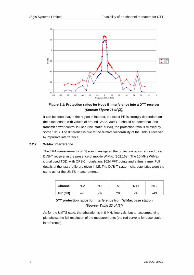
point is met at an interferer level of -35dBm. In figure 2.3 below [4], the BBC have
extrapolated this requirement based on the assumption of a perfectly linear AGC
characteristic (dotted red curve).
Figure 2.3: BBC out-of-band interference measurements (source: BBC)
The actual performance of a number of set-top box DTT receivers was compared
against this curve, showing that linearity is generally lost at signal levels above
about -15dBm. This does not necessarily imply failure, but does desensitise the
receiver.
The impact of receiver operating point on protection ratio was also investigated in a
further ERA report for Ofcom [5], concerned with interference between different DTT
services. The scenario examined in this report is not directly relevant, but is of
interest. In these measurements, the protection ratio required to protect a wanted
(64-QAM) DVB-T service from adjacent channel (16-QAM) DVB-T interference was
evaluated, for different levels of the wanted signal. It can be seen that non-linearity
sets in at similar signal levels (the relatively worse performance at the higher
channel is noteworthy).
Ægis Systems Limited Feasibility of on-channel repeaters for DTT
2109/OCR/R/3.0 7
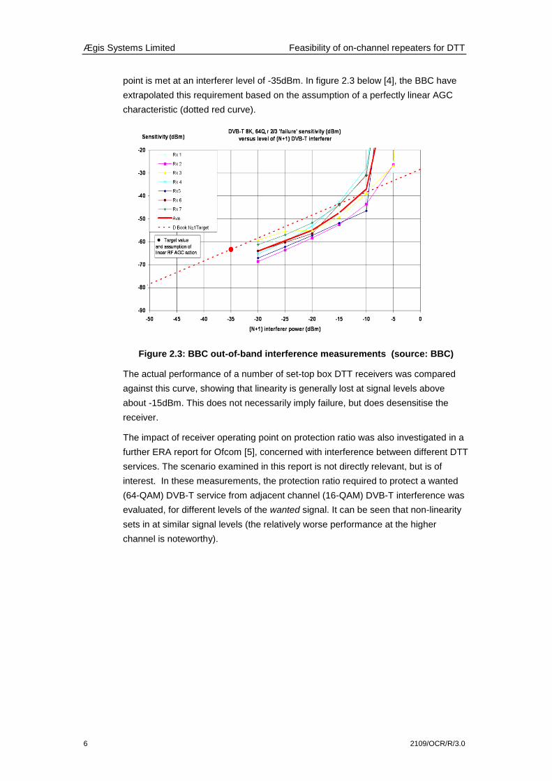
Figure 2.4: ACI Protection ratios for DTT-DTT interference at different wanted
signal levels (Source: Figure 10 of [4])
This shows that the ability of the receiver to discriminate against ACI falls as the RF
input level rises.
It seems (see Annex C) that SE42 have (tentatively) adopted an overload threshold
of -9dBm for power in the adjacent channel, and this seems an appropriate figure.
At Channel 61, and assuming an antenna system gain of 7dBd, -9dBm corresponds
to 117.2 dBμV/m, which is the field strength at around 300m from a transmitter with
1kW ERP.
It should be borne in mind, however, that this is not a „hard‟ limit; the impact of such
overloading will depend on the absolute and relative levels of both signals. A useful
model might plot coverage areas on the basis of a C/I criterion that was a function of
absolute signal levels at the receiver.
2.4 Practical Impact of ‘hole-punching’
Cellular sites are increasingly making use of dual polarised (+/- 45°) antennas for
receive diversity, with one polarisation only used for transmission. It is the
expectation of at least one UK operator that dual polarisation will be employed for
any 800 MHz mobile network. This implies that the interference impact to DTT
reception will be the same regardless of the polarisation used by the DTT service,
with only a 3dB cross polar protection available to either VP or HP rooftop aerials.
The size of the interference area around the ECN site will depend on the distance
between that site and the DTT transmitter, and the shape of the area will reflect the
radiation pattern of the domestic receive aerials. The interference will have
maximum extent in the case where domestic aerials are pointing through the ECN
site to the distant DTT transmitter.
Ægis Systems Limited Feasibility of on-channel repeaters for DTT
8 2109/OCR/R/3.0
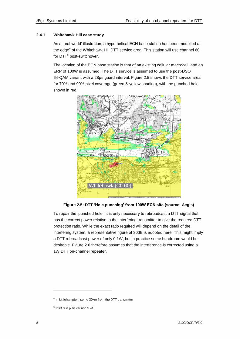
2.4.1 Whitehawk Hill case study
As a „real world‟ illustration, a hypothetical ECN base station has been modelled at
the edge4 of the Whitehawk Hill DTT service area. This station will use channel 60
for DTT5 post-switchover.
The location of the ECN base station is that of an existing cellular macrocell, and an
ERP of 100W is assumed. The DTT service is assumed to use the post-DSO
64-QAM variant with a 28μs guard interval. Figure 2.5 shows the DTT service area
for 70% and 90% pixel coverage (green & yellow shading), with the punched hole
shown in red.
Figure 2.5: DTT ‘Hole punching’ from 100W ECN site (source: Aegis)
To repair the „punched hole‟, it is only necessary to rebroadcast a DTT signal that
has the correct power relative to the interfering transmitter to give the required DTT
protection ratio. While the exact ratio required will depend on the detail of the
interfering system, a representative figure of 30dB is adopted here. This might imply
a DTT rebroadcast power of only 0.1W, but in practice some headroom would be
desirable. Figure 2.6 therefore assumes that the interference is corrected using a
1W DTT on-channel repeater.
4 In Littlehampton, some 30km from the DTT transmitter
5 PSB 3 in plan version 5.41

Ægis Systems Limited Feasibility of on-channel repeaters for DTT
2109/OCR/R/3.0 9
Figure 2.6: DTT ‘Hole filling’ with 1W OCR (source: Aegis)
As expected, the original hole is repaired. It can be seen, however, that the pattern
of coverage is slightly different at the edge of the service area, with a few
previously-served pixels experiencing interference due to out-of-guard-interval
echoes.
It is interesting to examine the impact if an OCR is implemented using the current
2K variant of the DVB-T standard, with a 7μs guard interval.
Figure 2.7: DTT ‘Hole filling’ with 1W OCR (2k system) (source: Aegis)
Ægis Systems Limited Feasibility of on-channel repeaters for DTT
10 2109/OCR/R/3.0
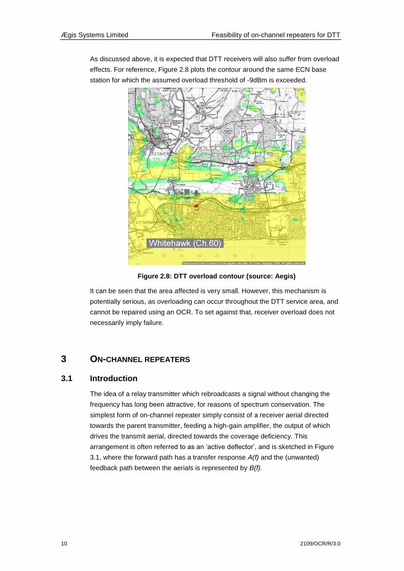
As discussed above, it is expected that DTT receivers will also suffer from overload
effects. For reference, Figure 2.8 plots the contour around the same ECN base
station for which the assumed overload threshold of -9dBm is exceeded.
Figure 2.8: DTT overload contour (source: Aegis)
It can be seen that the area affected is very small. However, this mechanism is
potentially serious, as overloading can occur throughout the DTT service area, and
cannot be repaired using an OCR. To set against that, receiver overload does not
necessarily imply failure.
3 ON-CHANNEL REPEATERS
3.1 Introduction
The idea of a relay transmitter which rebroadcasts a signal without changing the
frequency has long been attractive, for reasons of spectrum conservation. The
simplest form of on-channel repeater simply consist of a receiver aerial directed
towards the parent transmitter, feeding a high-gain amplifier, the output of which
drives the transmit aerial, directed towards the coverage deficiency. This
arrangement is often referred to as an „active deflector‟, and is sketched in Figure
3.1, where the forward path has a transfer response A(f) and the (unwanted)
feedback path between the aerials is represented by B(f).

Ægis Systems Limited Feasibility of on-channel repeaters for DTT
2109/OCR/R/3.0 11
Figure 3.1: Simple ‘active deflector’ (source: Aegis)
The first such equipment in regular use in the UK was at a UHF television relay at
Bethesda, in Snowdonia, operational in 1971. Such methods were not widely
adopted during the analogue era for two main reasons; firstly, it is very difficult to
ensure sufficient isolation between receive and transmit aerials to avoid instability or
oscillation and, secondly, analogue receivers require very high levels of C/I – there
are very few cases where the target coverage area is sufficiently well-screened from
the parent transmitter to avoid very significant multipath interference (ghosting).
In the case of the Bethesda relay, the target area is on the side of a hill facing away
from the main transmitter (Llanddona), giving very large diffraction losses and
ensuring that this transmitter would not cause interference. The problem of isolation
was solved by locating the transmit and receive aerials on separate masts some
36m apart, and making use of trough antennas with good discrimination for off-axis
signals. At Bethesda, the isolation between aerial ports is ~100dB, and the gain
through the deflector is ~60dB, giving an output power of 1W (25W ERP).
With the availability of fast digital signal processing (DSP) and the DVB-T standard,
both problems can be solved. DSP techniques can be used to implement adaptive
echo cancellers, while DVB-T receivers not only have C/I requirements that are
smaller than for analogue systems, but are specifically resistant to multipath, so long
as the interference falls within the system Guard Interval (GI).
3.2 Digital OCR technology
The basic technique in digital OCRs is to convert the received signal to digital form,
in which it can be corrected using an echo-cancelling filter, before being converted
back to analogue form for re-transmission. The filter characteristics are determined,
dynamically, by a channel estimator, the aim of which is to set the response of the
filter, C(f), to precorrect or neutralise the forward path. A transversal filter is
generally used, the number of taps used being one of the many trade-offs between
response time, throughput delay and cancellation effectiveness.
A(f)
B(f)

Ægis Systems Limited Feasibility of on-channel repeaters for DTT
12 2109/OCR/R/3.0
Figure 3.2: Basic digital OCR (source: Aegis)
Within this basic framework, a number of detailed implementations may be adopted,
the main variations relating to the method used for estimating the required filter
response.
One conceptually simple approach is to embed a reference training signal within the
output of the repeater. This readily identified signal can then be used to determine
the necessary filter coefficients in a computationally-efficient manner, as shown in
Figure 3.3.
.
Figure 3.3: OCR with training sequence (source: Aegis)
Although this method allows short delay times, and minimises installation
complexity, it suffers from a number of disadvantages. The most severe problem is
that, because the training sequence must be added to the DVB-T output of the
repeater, the C/N ratio is degraded at the point of transmission.
Rather than adding a special training sequence, another option is for the channel
estimator to make use of the scattered pilots within the DVB-T COFDM signal. This
approach avoids the C/N degradation, but with the penalty of a significantly longer
convergence time for the channel estimation. This may well be problematic in
practical implementations where there is considerable time-variability in the channel
due to reflections from trees, vehicles, etc.
A further variant, patented [12] by the BBC, is non-system specific and removes the
need to add any signals to the repeater output. Instead, a deliberate delay is added
A(f)
Estimator
B(f)
Filter C(f)
A(f)
Estimator
B(f)
Filter C(f)
PRBS
Ægis Systems Limited Feasibility of on-channel repeaters for DTT
2109/OCR/R/3.0 13
in the signal path through the repeater, to ensure that the received and transmitted
signals are uncorrelated6. Using these methods, with a least mean square (LMS)
algorithm for the estimation of filter taps, has been claimed [8] to give some 50dB of
echo cancellation.
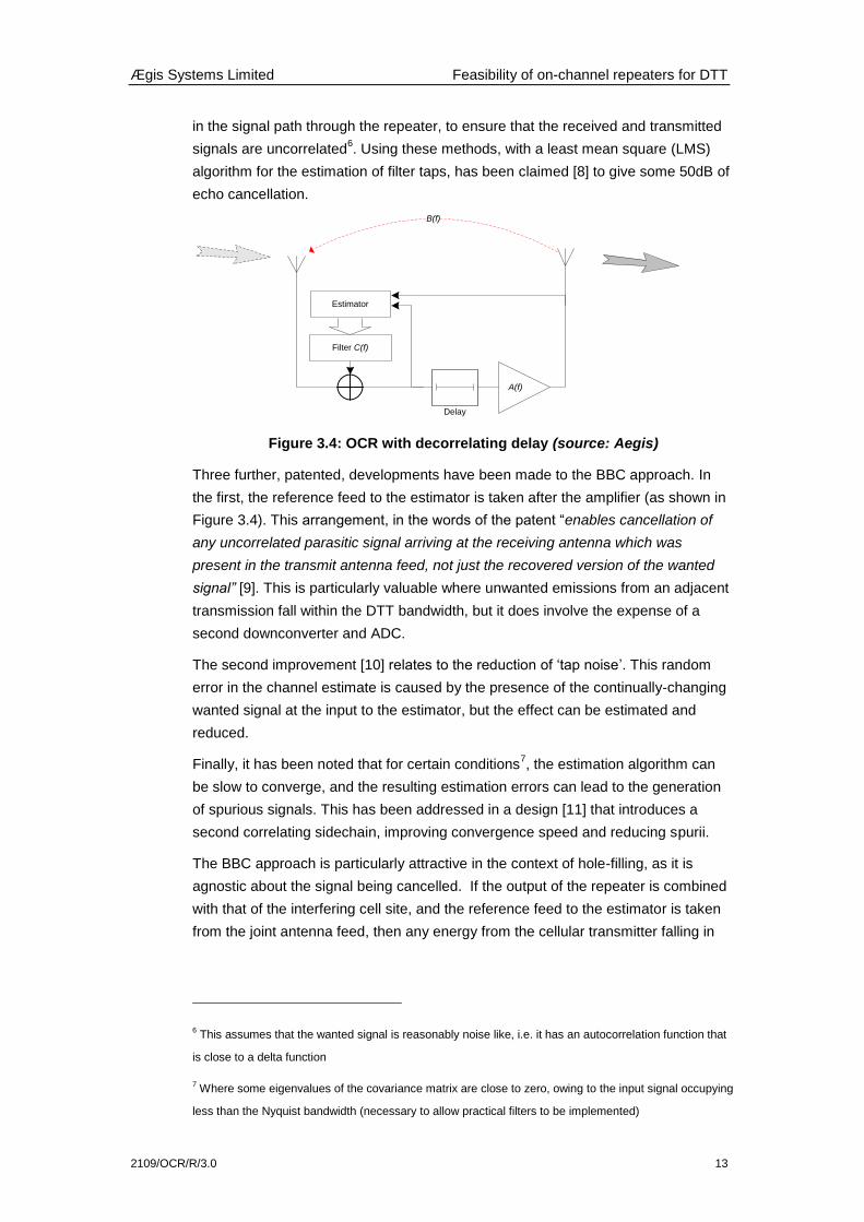
Figure 3.4: OCR with decorrelating delay (source: Aegis)
Three further, patented, developments have been made to the BBC approach. In
the first, the reference feed to the estimator is taken after the amplifier (as shown in
Figure 3.4). This arrangement, in the words of the patent “enables cancellation of
any uncorrelated parasitic signal arriving at the receiving antenna which was
present in the transmit antenna feed, not just the recovered version of the wanted
signal” [9]. This is particularly valuable where unwanted emissions from an adjacent
transmission fall within the DTT bandwidth, but it does involve the expense of a
second downconverter and ADC.
The second improvement [10] relates to the reduction of „tap noise‟. This random
error in the channel estimate is caused by the presence of the continually-changing
wanted signal at the input to the estimator, but the effect can be estimated and
reduced.
Finally, it has been noted that for certain conditions7, the estimation algorithm can
be slow to converge, and the resulting estimation errors can lead to the generation
of spurious signals. This has been addressed in a design [11] that introduces a
second correlating sidechain, improving convergence speed and reducing spurii.
The BBC approach is particularly attractive in the context of hole-filling, as it is
agnostic about the signal being cancelled. If the output of the repeater is combined
with that of the interfering cell site, and the reference feed to the estimator is taken
from the joint antenna feed, then any energy from the cellular transmitter falling in
6 This assumes that the wanted signal is reasonably noise like, i.e. it has an autocorrelation function that
is close to a delta function
7 Where some eigenvalues of the covariance matrix are close to zero, owing to the input signal occupying
less than the Nyquist bandwidth (necessary to allow practical filters to be implemented)
A(f)
Estimator
B(f)
Filter C(f)
Delay

Ægis Systems Limited Feasibility of on-channel repeaters for DTT
14 2109/OCR/R/3.0
the DTT channel (e.g. from intermodulation products, or sideband re-growth) will be
cancelled as effectively as the output of the repeater.
3.3 Specifications and commercial hardware
This section makes a comparison between six different OCR implementations - two
prototype designs and four commercial implementations. It is known that several
other manufacturers (including Plisch and MIER, who demonstrated the first DTT
on-channel repeater in Berlin in 1997) produce apparently suitable designs.
3.3.1 BBC R & D design
The BBC prototype DVB-T on-channel repeater implements the patented designs
and algorithms described above.
Figure 3.5: BBC DVB-T on-channel repeater (source: BBC)
This unit has been developed as a prototype and testbed, rather than an operational
unit. The design has, however, been licensed to a number of manufacturers
3.3.2 ‘PLUTO’ project
The PLUTO project (Physical Layer DVB Transmission Optimisation) is supported
by the EU 1ST
programme and is examining novel techniques for broadcast
transmitter networks. One aspect of the research has been the investigation of echo
cancelling techniques for low-cost on-channel repeaters.
Significant development work has been undertaken at Brunel University, led by
Professor John Cosmas. The aim of this work has been to investigate and assess
methods for echo-cancellation, rather than to develop an operational piece of
hardware. Laboratory test have been undertaken with the prototype, but not field
trials.
The work is of interest because it uses a rather different approach to that of the
BBC, injecting a training signal into the output of the repeater, to provide a reference
for channel characterisation, as in Figure 3.3. The training signal used is a Constant
Amplitude Zero AutoCorrelation (CAZAC) sequence.
Ægis Systems Limited Feasibility of on-channel repeaters for DTT
2109/OCR/R/3.0 15
The design is constrained by the decision to ensued compatibility with the 2k DVB-T
mode, and thus to limit the delay to ~2μs. Nevertheless, reported cancellation
values of 20-50dB are reported for a single 1μs echo, dependant on the relative
echo power.
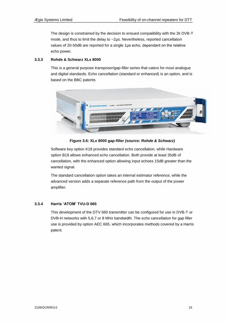
3.3.3 Rohde & Schwarz XLx 8000
This is a general purpose transposer/gap-filler series that caters for most analogue
and digital standards. Echo cancellation (standard or enhanced) is an option, and is
based on the BBC patents
Figure 3.6: XLx 8000 gap-filler (source: Rohde & Schwarz)
Software key option K18 provides standard echo cancellation, while Hardware
option B19 allows enhanced echo cancellation. Both provide at least 35dB of
cancellation, with the enhanced option allowing input echoes 15dB greater than the
wanted signal.
The standard cancellation option takes an internal estimator reference, while the
advanced version adds a separate reference path from the output of the power
amplifier.
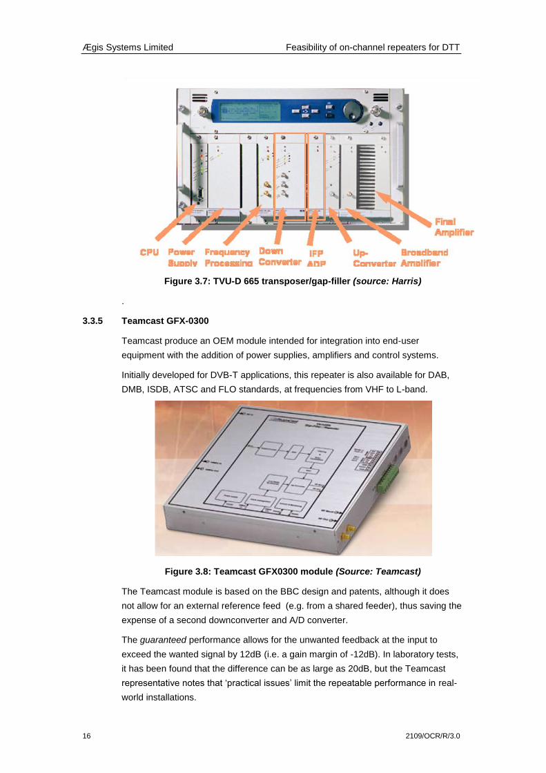
3.3.4 Harris ‘ATOM’ TVU-D 665
This development of the DTV 660 transmitter can be configured for use in DVB-T or
DVB-H networks with 5,6,7 or 8 MHz bandwidth. The echo cancellation for gap filler
use is provided by option AEC 665, which incorporates methods covered by a Harris
patent.
Ægis Systems Limited Feasibility of on-channel repeaters for DTT
16 2109/OCR/R/3.0
Figure 3.7: TVU-D 665 transposer/gap-filler (source: Harris)
.
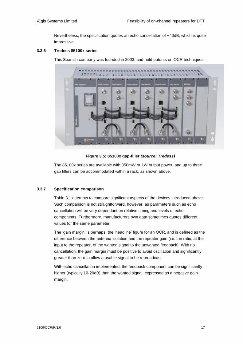
3.3.5 Teamcast GFX-0300
Teamcast produce an OEM module intended for integration into end-user
equipment with the addition of power supplies, amplifiers and control systems.
Initially developed for DVB-T applications, this repeater is also available for DAB,
DMB, ISDB, ATSC and FLO standards, at frequencies from VHF to L-band.
Figure 3.8: Teamcast GFX0300 module (Source: Teamcast)
The Teamcast module is based on the BBC design and patents, although it does
not allow for an external reference feed (e.g. from a shared feeder), thus saving the
expense of a second downconverter and A/D converter.
The guaranteed performance allows for the unwanted feedback at the input to
exceed the wanted signal by 12dB (i.e. a gain margin of -12dB). In laboratory tests,
it has been found that the difference can be as large as 20dB, but the Teamcast
representative notes that „practical issues‟ limit the repeatable performance in real-
world installations.
Ægis Systems Limited Feasibility of on-channel repeaters for DTT
2109/OCR/R/3.0 17
Nevertheless, the specification quotes an echo cancellation of ~40dB, which is quite
impressive.
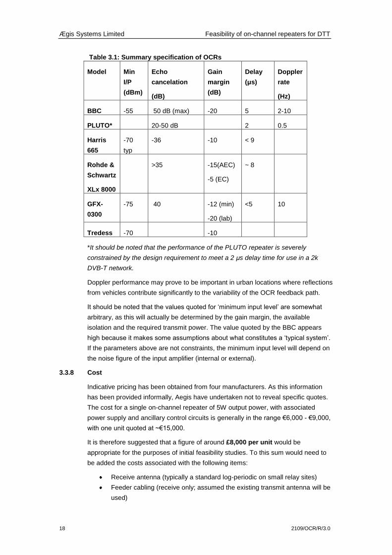
3.3.6 Tredess 85100x series
This Spanish company was founded in 2003, and hold patents on OCR techniques.
Figure 3.5: 85100x gap-filler (source: Tredess)
The 85100x series are available with 350mW or 1W output power, and up to three
gap fillers can be accommodated within a rack, as shown above.
3.3.7 Specification comparison
Table 3.1 attempts to compare significant aspects of the devices introduced above.
Such comparison is not straightforward, however, as parameters such as echo
cancellation will be very dependant on relative timing and levels of echo
components. Furthermore, manufacturers own data sometimes quotes different
values for the same parameter.
The „gain margin‟ is perhaps, the „headline‟ figure for an OCR, and is defined as the
difference between the antenna isolation and the repeater gain (i.e. the ratio, at the
input to the repeater, of the wanted signal to the unwanted feedback). With no
cancellation, the gain margin must be positive to avoid oscillation and significantly
greater than zero to allow a usable signal to be rebroadcast.
With echo cancellation implemented, the feedback component can be significantly
higher (typically 10-20dB) than the wanted signal, expressed as a negative gain
margin.
Ægis Systems Limited Feasibility of on-channel repeaters for DTT
18 2109/OCR/R/3.0
Table 3.1: Summary specification of OCRs
Model Min
I/P
(dBm)
Echo
cancelation
(dB)
Gain
margin
(dB)
Delay
(μs)
Doppler
rate
(Hz)
BBC -55 50 dB (max) -20 5 2-10
PLUTO* 20-50 dB 2 0.5
Harris
665
-70
typ
-36 -10 < 9
Rohde &
Schwartz
XLx 8000
>35 -15(AEC)
-5 (EC)
~ 8
GFX-
0300
-75 40 -12 (min)
-20 (lab)
<5 10
Tredess -70 -10
*It should be noted that the performance of the PLUTO repeater is severely
constrained by the design requirement to meet a 2 μs delay time for use in a 2k
DVB-T network.
Doppler performance may prove to be important in urban locations where reflections
from vehicles contribute significantly to the variability of the OCR feedback path.
It should be noted that the values quoted for „minimum input level‟ are somewhat
arbitrary, as this will actually be determined by the gain margin, the available
isolation and the required transmit power. The value quoted by the BBC appears
high because it makes some assumptions about what constitutes a „typical system‟.
If the parameters above are not constraints, the minimum input level will depend on
the noise figure of the input amplifier (internal or external).
3.3.8 Cost
Indicative pricing has been obtained from four manufacturers. As this information
has been provided informally, Aegis have undertaken not to reveal specific quotes.
The cost for a single on-channel repeater of 5W output power, with associated
power supply and ancillary control circuits is generally in the range €6,000 - €9,000,
with one unit quoted at ~€15,000.
It is therefore suggested that a figure of around £8,000 per unit would be
appropriate for the purposes of initial feasibility studies. To this sum would need to
be added the costs associated with the following items:
Receive antenna (typically a standard log-periodic on small relay sites)
Feeder cabling (receive only; assumed the existing transmit antenna will be
used)

Ægis Systems Limited Feasibility of on-channel repeaters for DTT
2109/OCR/R/3.0 19
Mounting hardware / racking
230 V power supply wiring
Control/monitoring system (details will depend on the organisation having
responsibility for the OCR; if this is the ECN network, it is assumed that
state outputs of the OCR will be integrated with the ECN monitoring system)
The most significant additional cost is likely to be associated with the need to align
the transmit and receive aerials to maximise received DTT signal and mutual
isolation. Accounting for the additional hardware, planning and installation costs an
initial, tentative, estimate of £15,000 per site for the addition of an OCR is
proposed.
4 PRACTICAL IMPLEMENTATION ISSUES
4.1 Power levels at repeater input
The worst-case situation will relate to cellular sites near the edge of coverage of a
DTT service. In such cases, the DTT repeater will have a wanted input signal of only
around 40dBuV (depending on the receive aerial system), or ~-70dBm.
The repeater will need to operate reliably in the face of much larger inputs (i) on the
same channel from the re-radiated DTT and (ii) on the adjacent channel from the
cellular transmissions.
The unwanted DTT feedback can only be reduced by careful positioning of the DTT
receive and transmit aerials on the mast. A typical, relatively easily-achieved
isolation on a larger mast is in the order of 70dB. Assume an ECN power of 50dBm
(ERP) and a DTT power of 20dBm8. Then the unwanted signals will be -20dBm
(adjacent) and -50dBm (co-channel).
If it is further assumed that the ACI at the repeater input can be reduced by 30dB
with a good filter (limited by the steep roll-off, and the need for good group delay
across the DTT channel), both levels will be -50dBm.For the co-channel signal, this
represents an unwanted signal 20dB higher than the wanted, or a gain margin of -
20dB.
The majority of the OCRs discussed in Section 3 would be unable to cope with such
a high level of unwanted signal, implying that it will be challenging to deploy OCRs
at the limit of coverage, where they will be most needed, unless significant
improvements can be made to antenna isolation.
It must be stressed, however, that such cases will be in a minority. In a Vodafone
study communicated to SE42 (see Section 5.3 below) it was found that 90% of
existing macro cell sites examined would have an available DTT input signal above
the -55dBm signal required by the BBC OCR design.
8 The minimum needed to repair the coverage at an assumed ACI protection ratio of -30dB
Ægis Systems Limited Feasibility of on-channel repeaters for DTT
20 2109/OCR/R/3.0
4.2 Polarisation issues
DTT transmissions will generally be horizontally polarised from main station
transmitters9, and generally vertically polarised from relay sites. Cellular radio
services were, originally, transmitted using vertical polarisation, which would imply
that, although there would be no additional protection within most relay service
areas, some 16dB of discrimination10
could be available to DTT receivers in main
station coverage areas.
In current practice, however, dual polarisation antennas are generally used to
achieve diversity gain at the BS receiver. Both H/V and +45°/- 45° formats are used,
with the latter preferred, due to the higher diversity gain available. This is perhaps
unfortunate from the point of view of compatibility with adjacent-channel DTT
services, as only 3dB discrimination will now be available in main station areas
(although the situation in relay station areas is somewhat improved.
It may, therefore, be worthwhile to arrange that VP is always used for transmission
at ECN sites falling in main station service areas; polarisation diversity could still be
applied on receive, though this might be sub-optimum if based on H/V elements.
The situation at VP relay sites is less clear cut, as a move to HP by the ECN
transmitter might reduce the cell size significantly, necessitating either an increase
in transmit power, or a higher cell density. Either approach would negate the benefit
of the polarisation change. It is, therefore likely that in these areas the ECN will
need to retain +45°/-45° polarisation, and accept that only 3dB discrimination will be
available.
One ameliorating factor for the relay station case is that the usable field strength at
the edge of coverage is generally higher than that for main stations, the coverage
being limited by steep terrain or high levels of co-channel interference. This will
make DTT receivers less vulnerable to ACI.
4.3 Combining of DTT signals
There are very strong arguments for using the same antenna for both the ECN and
DTT services. The most obvious advantages are the savings in cost and space.
Additionally, use of the same antennas will ensure that the difference in field
strength between the two services will remain as constant as possible, with
variations arising only because of differences in multipath fading due to the slightly
different wavelengths. Finally, as noted in Section 3, if the same antennas are used,
9 A significant exception is Rowridge, which will radiate both HP and VP components after DSO
10 ITU-R Recommendation quotes a figure of 16dB for the cross-polar discrimination to be assumed for
domestic television receive antennas

Ægis Systems Limited Feasibility of on-channel repeaters for DTT
2109/OCR/R/3.0 21
it becomes possible to cancel intermodulation products from the ECN that fall in the
DTT channel.
Against these arguments the practical difficulties of combining the two services must
be considered. Given the low power that is likely to be required from the DTT
transmitter, it would not be unreasonable to use a simple 10dB coupler to inject the
signal from the OCR into the transmit path of the ECN base station.
The majority of ECN sites are sectored, to maximise capacity, with individual
antennas covering an arc of, e.g. 120°. In this case, it may to be necessary to
provide DTT signals to all sectors, although ACI will be most severe in the sector
towards which TV aerials are pointed. The simplest approach will be to use a single
OCR with a higher power, and to split the output as required to drive the coupler in
each feeder. A potential problem with this arrangement is that there are now
multiple feedback paths from the output to input of the OCR, and this may pose
problems for the echo cancellation algorithms.
4.4 Installation of receiving aerials
The location of the receiving aerial on an OCR site is generally a compromise,
between (i) maximising the wanted signal, (ii) minimising multipath, unwanted SFN
components and interference and (iii) maximising isolation. (i) will generally imply
that the aerial should be as high as possible, while (iii) will suggest maximising the
distance between the transmit aerial (likely to be sited at the top of the mast) and
the receive aerial.
Trough aerials are often used for Re-Broadcast Links (RBL) at TV relay sites, but
create significant wind loading, and occupy considerable mast space.
While larger macrocell sites using lattice towers are likely to offer reasonable scope
for appropriate relative aerial positioning, this is may not generally be possible on
the smaller „monopole‟ type installations (a single, fat mast, akin to a streetlight, with
a cylindrical radome at the top).
Even on larger (e.g. 30m) lattice masts, there are often so many installed antennas
that (i) clear aperture at the correct height and bearing may be hard to find and (ii)
significant levels of scattering may degrade isolation.
Measurements of achievable isolation on a variety of operational masts would be
very valuable.
4.5 Knock-on impact to Channel 59
A few DTT transmitter sites will, post-DSO, use both channels 59 and 60. In these
areas, there is a danger that the act of repairing a hole on channel 60 will cause a
new hole to be created on channel 59.
Suppose the received DTT power on channels 59 and 60, from a distant transmitter
at a domestic site is -60dBm, but that adjacent channel interference on ch.60 is

Ægis Systems Limited Feasibility of on-channel repeaters for DTT
22 2109/OCR/R/3.0
caused by a local ECN transmitter which gives rise to a power of -25 dBm at the
domestic receiver input. This interference might be repaired by the use of an OCR
with a power 20dB below that of the ECN transmitter.
The input power at the domestic receiver on Ch.60 will then be -45dBm, giving a
protection ratio of -15dB to the ch.59 signal, well within the -25dB limit for adjacent
channel interference between DTT services [1]. For receive sites closer to the ECN,
however, the ch.59 power will remain fairly constant, while that on channel 60 will be
greater.
Interference by the ch.60 OCR to the channel 59 service will occur when the power
of the former exceeds -35dBm. At this point, however, the power from the ECN will
be -15dBm, and, from Figure 2.3, some receiver overload effects may be evident.
It therefore seems that, although there may be some cases where a channel 60
gap-filler will cause interference to channel 59 services, any areas affected will be
rather small annuli around the zones in which the interference mechanism will be
receiver overloading.
The following sites are planned to use both channels 59 and 60.
Table 4.1: DTT sites using both channel 59 and 60
Site Power (ch.59/ch.60) Polarisation
Oxford 47 / 50 dBW H
Selkirk 40 / 37 dBW H
Brierley Hill 33 / 33 dBW V
Salisbury 33 / 33 dBW V
Malvern 26 / 26 dBW V
4.6 DVB-T2
DVB-T2, the recently adopted (summer 2008) upgrade to the DVB-T standard offers
very significant capacity improvements, as well as other benefits, and field trials are
currently underway in the London area.
The principal changes in the new standard are a greatly improved coding scheme
(using LDPC/BCH codes) which approaches the Shannon limit as closely as is
practicable, combined with the use of higher-order modulation (256 QAM). Other
improvements (longer interleaving and the use of „rotated constellations‟) add
robustness in the face of impulsive noise and adverse propagation channels.
It appears that the majority11
of OCR designs should be compatible with DVB-T2;
this would certainly apply to those schemes which rely on the noise-like character of
11 The exception would be any device that made use of the pilots of a DVB-T signal to extract channel
information; no such equipment has, however, been explicitly identified in this brief survey

Ægis Systems Limited Feasibility of on-channel repeaters for DTT
2109/OCR/R/3.0 23
OFDM signals, such as the BBC (Rohde & Schwarz, Teamcast) and MIER designs.
The PLUTO approach, which uses a separate training sequence would also be
compatible. That said, none of the manufacturers approached had yet had the
opportunity to confirm the performance of their product in a DVB-T2 network.
It might be valuable to confirm correct operation of one or more devices during the
current DVB-T2 trials from Crystal palace.
5 EXISTING STUDIES
5.1 DAB repeaters
Most experience with on-channel repeaters in the UK has been related to the DAB
network, and to the development and use of the BBC OCR designs [6], [7]. In the
trial reported at Mapperley Ridge [6], the OCR design was not greatly stretched,
owing to the good isolation and high signal strength available. The high-power
Otford trial in [7] is more revealing, as the aerial isolation was fairly low (69dB), the
radiated power high (175W) and the impulse response at the input to the repeater
was challenging. The Otford site is part of a London DAB network, and many active
echoes are present at the input, even using a pair of phased yagis.
In particular, it was found that pre-echoes at more than -12dB with respect to the
wanted signal generated post-echo components that could exceed the guard
interval at the receiver. While this could be corrected by appropriate choice of OCR
delay, it was found that large (>-3dB) post-echoes caused the output BER to
degrade significantly. This problem was addressed by changes to the algorithm,
implementing additional filters that could be targeted to specific SFN components.
The feedback path between the aerials was also found to be more variable than had
been expected, with rapid phase and amplitude changes caused by structural
movement of mast and antennas. A modified estimation algorithm was implemented
to allow faster convergence and, incidentally, to permit the addition of the post-echo
filters mentioned above.
5.2 Operational systems
The use of on-channel repeaters is an established, and mature, technique for
coverage extension in DVB-T networks. In Spain, for example, the DTT networks
have been planned as large area SFNs, and make substantial use of OCRs.
The early requirement for SFN coverage extension in Spain has inspired companies
such as Tredess and MIER to take a particular interest in OCR techniques. MIER
have recently won an exclusive contract for the supply of relay transmitters to the
commercial Danish DTT operator, BSD. The majority of these sites will be
implemented as on-channel repeaters.
The need to minimise multipath on the input of OCRs was stressed by several
operators, noting the need for careful antenna positioning, and the use of

Ægis Systems Limited Feasibility of on-channel repeaters for DTT
24 2109/OCR/R/3.0
cancellation algorithms that allow the user to target specific active echoes at fixed
delay times.
5.3 CEPT SE42
While there is a fairly extensive literature in the academic and patent areas on the
design of on-channel repeaters, and a familiarity with their use for coverage
extension, there appears to be far less information on the practicalities surrounding
their use to repair hole-punching.
One group that has recently taken an interest in the topic is CEPT SE42, whose
brief includes “Flexible bands, WAPECS and new sharing approaches”. Two
contributions have recently been made to the group on this subject.
The first document, SE42(09)087 from Vodafone, proposed on-channel repeaters
as a mitigation technique for hole-punching, citing the BBC and PLUTO work and
noted that both the required output power and the hardware cost are low. Vodafone
report an internal study that examined the proportion of existing macrocell sites at
which the DTT signal would be sufficient (at least -55dBm) to feed an OCR of the
BBC design, finding that this was achieved for 90% of sites.
The second document, SE42(09)097, from Media Broadcast GmbH, took a rather
more sceptical attitude to the potential for coverage repair by OCRs. The document
reported a field trial carried out in Wolfsburg, in which trials were made of a number
of on-channel repeaters. The objective of the trials was coverage extension, rather
than interference mitigation. It was found that, although a high isolation was
achieved between transmit and receive antennas, the performance of the repeaters
was not wholly satisfactory, with a maximum cancellation of only 18dB (compared
with, for example, the 50dB claimed for the BBC design). The document attributes
this poor performance to the presence of “many „moving echoes‟” at the repeater
input, and reports that a conventional, frequency-translating solution was eventually
adopted at this site.
5.4 Discussion
The author has contacted the authors of both the SE42 documents. Vodafone stress
that their studies are at an early stage, and that the work reported was originally
intended for internal use. It is their view that, although the technique may not solve
all interference cases, it represents a powerful and valuable mitigation method.
Vodafone have provided the author with copies of two internal reports, and it
appears that the BBC figure of 50dB echo-cancellation is assumed as the starting
point for their feasibility assessment. It seems likely that this figure is somewhat
optimistic for real installed performance, however, with the implication that OCR use
might be possible at a smaller proportion of sites than supposed. The assessment of
available DTT signal levels at existing macrocell sites is, however, somewhat
pessimistic, as it only takes into account the main stations and larger relay sites (the
81 site plan, with a couple of additions), rather than the entire post-DSO network.
Ægis Systems Limited Feasibility of on-channel repeaters for DTT
2109/OCR/R/3.0 25
Media Broadcast elaborated on the Wolfburg trial, which took place two years ago,
stressing that the exercise was unrelated to interference mitigation, but was simply
to assess the options for the engineering of a new DTT transmitter. The DTT
network in this area uses an SFN with a long guard interval (8k, ¼ = 224μs), and the
rebroadcast source was a transmitter some 40km distant. In addition to the wanted
signal, a number of other active echoes were present on the input. Initial tests aimed
at determining the best location for transmit and receive aerials showed an isolation
of 90-100dB, a very good figure, probably aided by the fact that the installation was
on a concrete tower of ~50m height. When measurements were made on the final
aerials, it was found that the achieved isolation was only 84-94dB, and that this
varied, sometimes rapidly, with reflections. The site is in a forested area, and the
downtilt of the transmit aerial was felt to have enhanced reflections from the foliage.
Three OCRs were tested, from MIER and from Harris with powers of 20-100W, and
these exhibited throughput delays of 6-11μs. Despite the re-radiated signals being
well within the 224μs.guard interval, survey work revealed many areas where a pre-
existing service was lost when the OCR was brought into operation. The Wolfsburg
site now operates a conventional transposer.
The problems reported by Media Broadcast are interesting in that they appear to
relate to similar issues to those experienced by the BBC at Otford. Although the
number and relative timing of the SFN components on the input are not known, it is
possible that high level pre- or post-echoes, leading to spurious output and BER
degradation, might have been responsible for the reception failures reported.
Additionally, both trials reported significant variability of the aerial isolation.
These results suggest that it will be very important to characterise the environment
in which OCRs will operate, and to take into account the, often subtle, differences
between the algorithms employed by different manufacturers. It will not be adequate
simply to compare quoted gain margins with hypothetical aerial isolation figures.
On the positive side, the post-DSO DTT environment in the UK should be a more
benign environment than either the German DTT or UK DAB networks; being an
MFN, the problems with active pre- and post-echoes should be absent.
6 FIELD TRIALS
This brief survey suggests that on-channel DTT repeaters will be a useful took with
which to mitigate interference caused to DTT reception by new services using
frequencies above channel 60. Many of the issues, however, are not clear cut, and it
is suggested that it might be valuable for Ofcom to co-ordinate field trials.
Any such trials would need to be undertaken in an area in which DSO has already
occurred (e.g. South Devon or the Borders), as OCRs are only practical when
implemented within an 8k DVB-T network. Another option would be to make use of
the current DVB-T2 test transmissions from Crystal palace.

Ægis Systems Limited Feasibility of on-channel repeaters for DTT
26 2109/OCR/R/3.0
Ideally, such a trial would involve the use of an existing cell site, rigged with
appropriate antennas. This would imply a significant degree of co-operation and
expenditure by interested parties, and may not be practical. A very tentative
suggestion is therefore made below for a small-scale trial.
6.1 Small-scale trial proposal
An initial trial that might be undertaken with little delay might make use of temporary,
vehicle-mounted, transmitters.
It would be necessary to identify a largely unpopulated, but accessible, area towards
the edge of coverage of an 8K DTT transmitter.
Readily available cellular panel antennas are available with bandwidths extending
down to 806 MHz (Channel 63), but as these frequencies are to be released under
the original Digital Dividend plan no 8k transmitters will be operational on these
channels. It is therefore suggested that trials be carried out in the service area of a
site such as Huntshaw Cross (DSO in July 2009) that uses channel 62.
A Land Rover with transportable mast might be set up in the chosen test area, with
a test generator set to replicate, for example, a UMTS transmission on channel 63,
fed via a suitable power amplifier to the cellular antenna.
A separate UHF log-periodic aerial might be positioned on the mast to provide an
input to one or more OCR devices under investigation. The OCR output would be
combined, after amplification as necessary, with the UMTS signal using a 10dB
coupler. Although the cellular antenna will be operating outside its nominal
bandwidth at Channel 62 it is likely the degradation will be minor.
A second vehicle might then be used to survey DTT reception on channel 62 in the
test area with (i) no additional signals (ii) with the channel 63 UMTS signal and (iii)
with both OCR and UMTS operational.
Particular attention should be paid to the re-radiated impulse response, and to the
overall MER of the channel 62 DTT services.
7 CONCLUSIONS
On-channel repeaters are a well-established and mature option for use in the
coverage extension of DTT networks, and are widely deployed in, for example,
Spain and Denmark. They are not universally practical, however, particularly where
insufficient aerial isolation can be engineered, where the incoming DTT signal is
weak or where the input channel contains challenging (active and passive) multipath
components.
It seems likely that on-channel repeaters will be a useful technique for mitigating
adjacent channel interference to DTT services in the majority of cases. It is,
however, unlikely that they will provide a universal „plug and play‟ solution. In
particular, existing equipment may lack the performance to repair coverage

Ægis Systems Limited Feasibility of on-channel repeaters for DTT
2109/OCR/R/3.0 27
deficiencies at the edge of DTT service areas where available input field strengths
are low.
The following comments are offered.
1. There is a good choice of commercial OCR products on the market.
2. There is considerable variety in the designs and algorithms used in OCRs.
3. The interaction between specific OCR designs and the radio environment at
a given site is complex; care must be exercised in system design and
commissioning.
4. The radio environment in the post-DSO UK DTT network will be fairly
benign for OCR use, owing to the use of an MFN.
5. The practical restrictions on OCR receive aerial location are likely to be a
significant constraint on the deployment of OCRs.
6. It will generally be preferable to make use of the ECN aerial system for the
DTT transmissions, to minimise cost, mast loading and relative signal
variability.
7. The transmitter power required from OCRs is likely to be in the order of 1-
10W, depending on the combining arrangements chosen.
8. At these power levels, simple 10dB couplers should provide an appropriate
means of DTT signal injection.
9. It is estimated that the addition of a DTT repeater will cost in the region of
£15,000 per cellular site.
10. The majority of ECN sites will use sectored antennas. Careful consideration
will need to be given to the method of coupling DTT transmissions to
multiple sectors while maintaining a reliable radiation pattern, and to the
impact on the feedback path(s) seen by the OCR.
11. It is possible that an OCR on channel 60 could, itself, punch a hole in DTT
coverage on channel 59. Such problems would be limited to very small
areas within five DTT service areas, and could be repaired by the use of a
second OCR if necessary.
12. There may be a case of ensuring that any ECN base stations located within
the coverage areas of main DTT transmitters operating on channel 60 use
vertical, rather than 45°, polarisation.
13. It appears that most OCR devices will perform normally in the presence of a
DVB-T2 signal. This should be confirmed.
7.1 Recommendations
No practical studies appear to have been undertaken with regard to the use of
OCRs for coverage repair in DTT networks. The closest example is the BBC trial
reported in [6] in the context of DAB hole punching. Issues that appear to require
further work include:
The statistics of the feedback path between aerials on representative ECN
masts. It would be very useful to determine what isolation can be achieved
while ensuring a usable DTT input signal on a variety of operational masts.

Ægis Systems Limited Feasibility of on-channel repeaters for DTT
28 2109/OCR/R/3.0
The long-term and short-term variability (due to reflections, structural
flexing, etc) of the feedback channel should also be assessed.
It would be valuable to extend the internal work undertaken by Vodafone to
assess the available DTT input level at typical cell sites. Such an exercise
should make use of the current post-DSO frequency plan data.
The practical performance of a variety of OCR designs should be evaluated
in realistic conditions. Hardware design and algorithms vary significantly,
and will interact with the specific radio channel conditions.
Time has not permitted a comprehensive global survey of practical
experience with gap-fillers / OCRs. It would be worthwhile to continue to
seek information on OCR performance, especially in areas such as Spain
where SFNs are widely used.

Ægis Systems Limited Feasibility of on-channel repeaters for DTT
2109/OCR/R/3.0 29
A ANNEX A: REFERENCES
[1] “Technical Parameters and Planning Algorithms”, JPP document JPP/MB/1,
version 2, July 2003.
[2] “Conducted measurements to quantify different types of interference in the
DDR frequency spectrum”, ERA report 2007 - 0632 for Ofcom, October 2007.
Available at: www1.bsc.org.uk/research/technology/ctc/era05-07/
[3] “RF transmission and reception, RF test procedures”, Chapters 9 &10 of
“DTG „D-book‟,version 4, January 2005.
[4] “Results of high-level out-of-band DVB-T interference tests (S2)”, John Salter,
BBC R&D, February 2006, privately communicated to author.
[5] “Conducted measurements to quantify DVB-T interference into DTT
receivers”, ERA report 2007-0631 for Ofcom, October 2007. Available at:
www1.bsc.org.uk/research/technology/ctc/era05-07/
[6] Wiewiorka, A. and Moss, P.N., “Digital on-channel repeater for DAB”, BBC
R&D white paper, WHP120, 2005
[7] Kesby, P., Moss, P.N., Wiewiorka, A. “Practical development of high-power
on channel repeaters in DAB networks”, IBC 2008, Amsterdam.
[8] Specification of BBC DVB-T on-channel repeater, available at:
http://www.bbc.co.uk/rd/miscellaneous/licensing/on-channel-repeater/dvb-
t/index.shtml
[9] European Patent Application EP 1 724 946 A1 “Improvements relating to on-
channel repeaters” (BBC), Publication date: 22:11:2006, Bulletin 2006/47
[10] European Patent Application EP 1 931 063 A2 “On-channel repeater” (BBC),
publication date: 11:6:2008, Bulletin 2008/24
[11] United Kingdom Patent Application GB 2 454 082 A ““Improvements relating
to on-channel repeaters” (BBC), Publication date: 22:4:2009
[12] European Patent Application EP 1 931 063 A2 “OFDM Active Deflectors”
(BBC), publication date: 7:5:1997, Bulletin 1997/19
Ægis Systems Limited Feasibility of on-channel repeaters for DTT
30 2109/OCR/R/3.0
B ANNEX B: GLOSSARY
ADC Analogue to Digital Converter
AGC Automatic Gain Control
C/N Carrier to Noise ratio
COFDM Coded Orthogonal Frequency Division Multiplexing (modulation method used for
DVB-T and DAB transmission)
DSO Digital Switch-Over
DSP Digital Signal Processing
DTG Digital TV Group. The UK digital TV industry association
DTT Digital terrestrial TV
DVB-T The European terrestrial digital terrestrial TV standard
ECN Electronic Communications Network. A technologically neutral term to embrace
UMTS, WiMAX, LTE, etc, etc
HP Horizontal polarisation
MER Modulation Error Ratio
QAM Quadrature Amplitude modulation. Form of modulation in DVB-T offering
greatest data capacity
QPSK Quadrature Phase Shift Keying. The most robust form of modulation available in
DVB-T, offering lower data capacity
TDD Time Division Duplex
UMTS Universal Mobile Telecommunications System. Set of third generation mobile
standards
VP Vertical polarisation
WAPECS Wireless Access Policy for Electronic Communications Services. An EU concept
to promote technology and service neutral use of spectrum.
WiMax a set of standards for fixed and mobile wireless communications

Ægis Systems Limited Feasibility of on-channel repeaters for DTT
2109/OCR/R/3.0 31
C ANNEX C: WORK ON ADJACENT BAND COMPATIBILITY WITHIN THE
CEPT ELECTRONIC COMMUNICATIONS COMMITTEE (ECC)
Various study groups under CEPT ECC have been studying the implications of
adjacent band interference from Electronic Communications Network (ECN)
transmitters into DTT receivers in the 800 MHz band. In most cases, 10 MHz LTE is
assumed to be a proxy for the ECN technology. The following points are noted from
the discussions in contributions.
The size of the guard band at 790 MHz (which is the frequency boundary
between Ch 60 & 61)has been the subject of many contributions. In this
context, some studies indicate the need for a block edge mask (BEM) for
the protection of fixed DTT receivers from out-of-block emissions of ECN
base stations (BSs). One proposal is to use the DVB-T critical mask as the
BEM. Further proposal is to impose an EIRP limit of 0 dBm/8MHz (i.e. -19
dBm /100 kHz) which is based on interference analysis results indicating
that the reduction of the EIRP below this level does not affect the
percentage of DVB T receivers failing to meet the protection ratio
significantly due to the finite frequency selectivity of the TV receivers (Ref:
ECC PT1(09)072 Annex 3, April 2009).
In determining the constraints imposed by the proposed 0 dBm/8MHz limit,
additional filtering requirements together with appropriate guard bands are
examined. For example, it is suggested that (Ref: ECC PT1(09)048, April
2009) the proposed BEM EIRP limit is 27 dB more stringent than the LTE
BS emission mask (Ref: 3GPP TS 36.104) at the LTE channel edge.
Assumed ECN parameters include a BS in-block EIRP of 64 dBm/10 MHz
(where 15 dBi antenna gain is assumed including cable losses) and an
emission level of 8 dBm/100 kHz at the LTE channel edge.
Three RF filters have been designed to reduce the out-of-band emissions
for guard band options of 0, 1 and 2 MHz. The choice of guard bands from
0 to 2 MHz is the result of an agreement on maintaining 2x30 MHz paired
spectrum ( i.e. 6 paired blocks where each block is 5 MHz) with a minimum
10 MHz duplex gap in the band 790 – 862 MHz. It is suggested that (Ref:
ECC PT1(09)019, January 2009) the measured adjacent channel selectivity
of DVB-T receivers increases by up to 3 dB when the guard band is
increased from 0 to 2 MHz.
The implications of the filter cost and size for each guard band have been
considered. It is argued that the size of a filter for 1 MHz guard band is
roughly twice that of a filter for 2 MHz guard band. Furthermore, the cost of
a filter for 1 MHz guard band is approximately £40 greater than that of a
filter for a 2 MHz guard band. Further discussions have been directed

Ægis Systems Limited Feasibility of on-channel repeaters for DTT
32 2109/OCR/R/3.0
towards the impact of duplex gap and duplex spacing in the ECN FDD band
plan on ECN user terminals in terms of self-blocking and self-
desensitisation.
Issues related to the guard band and duplex gap are still under discussion.
In recent contributions, pros and cons of number of options that have been
put forward so far have been discussed. Some of proposals (Ref: ECC
PT1(09)064, April 2009) include the use of
o 2 MHz guard band and 10 MHz duplex gap,
o 1 MHz guard band and 11 MHz duplex gap,
o 12 MHz duplex gap together with restrictions on ECN operators
where the lowest frequency block size is reduced from 5 MHz to 3
MHz to provide 2 MHz frequency separation in geographic areas
where Ch 60 is used.
It is argued that without any frequency separation or ECN BS filtering it is
likely that the ECN downlink could not be used in bottom part of the ECN
FDD plan in areas where Ch 60 is used for DVB T. For mast mounted RF
heads, filters need to be a reasonable size and weight. In the context of
duplex gap, it is suggested that the duplexer is likely to be more complex
than UMTS900 technology for 10 MHz LTE with 10 MHz duplex gap and the
complexity is close to the limits of technology for the SAW technology which
is widely used by duplexer vendors. With the use of 12 MHz duplex gap, it
is suggested that the duplexer is not likely to be more complex than
UMTS900 duplexer. Therefore, cellular technology proponents favour 12
MHz duplex gap.
Further arguments by 12 MHz duplex gap proponents (Ref: ECC
PT1(09)098, April 2009) indicate that 800 kHz frequency separation at 790
MHz could be sufficient to meet the 0 dBm/8MHz BEM requirement by
introducing a filter with an achievable roll-off at ECN BS. It is further argued
that 700 kHz separation already exists due to 7.6 MHz effective bandwidth
in 8-MHz DVB-T channel and 9 MHz effective bandwidth in 10-MHz LTE
channel and by implementing a centre frequency shifting within the LTE
channel, a frequency separation of up to 1200 kHz could be achieved.
It is noted that ECC PT1 is waiting for the final decision from SE 42 on the
BEM before a final decision can be made on the guard band / duplex gap
(Ref: ECC PT1(09)098, April 2009).
In May 2009, a Draft CEPT Report titled „The identification of common and
minimal technical conditions for 790-862 MHz for the digital dividend in the
European Union‟ was published. The report states that the preferred
channelling arrangement is 2 x 30 MHz (starting at 791 MHz which indicates
a guard band of 1 MHz) with a duplex gap of 11 MHz based on a block size
Ægis Systems Limited Feasibility of on-channel repeaters for DTT
2109/OCR/R/3.0 33
in multiples of 5 MHz with reverse duplex direction (Ref: Draft ECC Report
133, May 2009). The same report also suggests that BEM for ECN BSs is 0
dBm/8MHz and in-block BS EIRP levels could be within the range 59 – 67
dBm / 10 MHz.
In Annex 3 of Draft Report 133, the protection ratio levels of -31 dB (Ch 61)
and -41 dB (Ch 62) and an overloading threshold level of -9 dBm have been
defined. Overloading analysis results indicate separation distances in the
range 160 – 320 metres for urban / rural scenarios where EIRP levels of 59
– 67 dBm together with DVB-T receiver antenna gain of 14.15 dBi and a
feeder loss of 5 dB are assumed. It is argued that when interfering BS is
not located within the DVB-T receiver main beam the required separation is
reduced significantly. For example, it is shown that the distance is reduced
below 70 metres when a gain reduction of 16 dB is introduced
(corresponding to 60 degrees off-axis angle).
A list of potential mitigation techniques is provided in Annex 2 of Draft
Report 133. These include DVB-T repeater co-sited with ECN BS,
cross/slant polarisation, reduced ECN BS transmit power, adjustment of
ECN BS antenna height, downtilt for ECN BS, increased DVB-T power,
additional filters for ECN BS transmitters and DVB-T receivers . Of
particular interest, in one of the latest contributions to SE 42 (Ref: ECC
SE42(09)083, May 2009), it is stated that a synchronisation mechanism for
SFN repeater or frequency management for MFN repeater may be
necessary when deploying DVB-T repeaters.
The following reference parameters are defined in Draft Report 133 for the
DVB-T system to be used in compatibility studies between ECN and DVB-T.

Ægis Systems Limited Feasibility of on-channel repeaters for DTT
34 2109/OCR/R/3.0
Operational frequency 470-862 MHz
Reference frequency 790 MHz
Bandwidth 8 MHz
Receiver noise figure 7 dB
Receiver C/N 21 dB
Receiver sensitivity -77.2 dBm
Receive antenna gain 12 dBd
Receive antenna feeder loss 5 dB
Receive antenna pattern Rec. BT 419-3
Polarisation H, V
Receive antenna height above ground level 10 m
Reference location probability 95%
Standard deviation used for the calculation of the location correction factor
5.5 dB
Reference (Emed)ref at fr = 790 MHz (10 m) 57.9 dB( V/m)
Environment urban, suburban, rural
Table C1: DVB-T System Parameters for Fixed Roof Level Antenna Reception
Holes in DVB-T coverage areas caused by ECN BS transmitters have been
derived for different scenarios. In one scenario (Ref: ECC SE42(09)045,
February 2009), holes within a coverage area of 50 x 50 SqKm served by
two DVB-T transmitters, each with 50 kW ERP, have been determined.
Assumed DVB-T parameter values for fixed reception are 16-QAM 2/3
modulation with a guard interval of ¼, C/N of 14.1 dB (fixed reception) and
protection ratios of -31 dB for interference from Ch 61 and -41 dB for
interference from Ch 62. DVB-T receiver antenna gain is assumed to be 11
dBd and the antenna directivity is assumed to be represented by ITU-R BT
419. The DVB-T service area has been populated by 50 ECN BS
transmitters each with EIRP of 64 dBm, 1-degree downtilt and 30 m height.
The BS transmitter vertical antenna pattern defined in the contribution is
taken into account. Using topographic and clutter data, it is shown that the
coverage holes appear towards the edge of DVB-T coverage area where
the wanted signal is faded.
Further analysis has investigated the overloading of fixed DVB-T receivers.
Assuming an overloading threshold of -15 dBm for each DVB-T receiver, it
is shown that the overloading is more serious problem than adjacent band
interference as the holes are more frequent and larger.

Ægis Systems Limited Feasibility of on-channel repeaters for DTT
2109/OCR/R/3.0 35
One recent contribution (Ref: ECC SE42(09)054r1, April 2009) outlines the
principles and assumptions used in various studies in the derivation of ECN
BS BEM. These are shown in the following table.

Ægis Systems Limited Feasibility of on-channel repeaters for DTT
36 2109/OCR/R/3.0
Reference DVB-T System 64-QAM 2/3
DVB-T Protection Ratios -30 dB (1st Adjacent Ch)
-40 dB (2nd
Adjacent Ch)
(Based on SE42(09)002 Annex 1
Tables 3 & 4)
(Note that PR levels of -31 & -41 dB are
used widely assumed in other
contributions)
DVB-T Receiver Overloading Threshold -9 dBm (1st Adjacent Ch)
-6 dBm (Other Channels)
DVB-T BS Transmitter Power & Height
(a.g.l.)
Class 1 : 10 kW ERP, 100 m (Urban)
Class 2: 50 – 100 kW ERP, 200 – 250
m (Rural)
DVB-T BS Antenna Pattern Elevation pattern defined in
SE42(09)014 which is flat at 0 dB level
for off-axis <= 1 deg, decreases to -10
dB at off-axis = 7 deg and then remains
constant until off-axis = 90 deg.
Azimuth pattern is assumed omni-
directional.
DVB-T Receiver Antenna Pattern ITU-R Rec. BT 419-3
DVB-T Receiver Antenna Height (a.g.l.) 10 m
DVB-T Minimum Median Wanted Field
Strength at 10 m
57.9 dBµV/m
(which translates as a minimum field
strength of 48.9 dBµV/m to be
exceeded at 95% locations)
DVB-T Receiver Polarisation
Discrimination
3 dB
(Cross-polar discrimination of 16 dB
cannot be imposed on a general level
but can be implemented on a local level
to solve specific problems)
ECN BS EIRP
(Assuming: Antenna Gain – Feeder Loss
= 15 dBi)
62 dBm / 10MHz (Typical Rural)
67 dBm / 10 MHz (Maximum Rural)
59 dBm / 10MHz (Typical Urban)
64 dBm / 10 MHz (Maximum Urban)
59 dBm / 10 MHz (Uplink Interference
Limited ECNs)
ECN BS Antenna Height 30 m (Urban)
60 m (Rural)

Ægis Systems Limited Feasibility of on-channel repeaters for DTT
2109/OCR/R/3.0 37
ECN BS Antenna Downtilt 0 degrees
ECN BS Antenna Pattern First Proposal: Elevation pattern defined
in SE42(09)014 which is flat at 0 dB
level for off-axis <= 5 deg, decreases to
-16 dB at off-axis = 15 deg and then
remains constant until off-axis = 90 deg.
Azimuth pattern is assumed omni-
directional.
(It is noted that CEPT Draft Report
published in May 2009 defines the
following elevation pattern (in Annex 3)
for ECN BS Antenna: flat at 0 dB level
for off-axis <= 2.5 deg, decreases to -15
dB at off-axis = 15 deg and then
decreases to -33 dB at off-axis = 90
deg)
Second Proposal: ITU-R Rec. F 1336
ECN Cell Size 2.7 km (Urban)
3.5 km (Rural)
(Based on uplink budget where user
terminal EIRP = 23 dBm for mobile & 28
dBm for fixed and the coverage
requirement is 95%)
Table C2: Assumptions Used in ECN BS BEM
Results of a field study of compatibility between DVB-T and UMTS (Ref:
ECC SE42(09)017, January 2009) indicate that interference signal levels
(as high as -14 dBm) approaching the overloading threshold of the DVB-T
receiver can be received at representative distances from the nearest
UMTS BS. It is therefore suggested to limit both the out-of-band and in-
band emissions of UMTS transmitters within the first 5 – 10 MHz above 790
MHz. Further observations suggest that the use of mixed polarisations at
UMTS BSs excludes the cross polarisation to mitigate the interference.
A study by ERA Technology for Ofcom (titled „Conducted measurements to
quantify different types of interference in the DDR frequency spectrum‟, July
2007) provides measured protection ratio values for both static and UMTS
downlink transmit power control (TPC) conditions (i.e. fast fading channel of
3 km/h) for interference from a UMTS BS into a typically performing DVB-T
receiver. Measurements are based on DVB-T system variant 8k 64-QAM
2/3. In the case of static interference scenario, the measured protection
ratio for N+1 is -41 dB and for N+2 is 45 dB. In the UMTS downlink

Ægis Systems Limited Feasibility of on-channel repeaters for DTT
38 2109/OCR/R/3.0
transmit power control scenario, the measured protection ratio for N+1 is
22 dB and for N+2 is -33 dB. The difference between the static and TPC
scenario results is due to the impulsive nature of the TPC conditions
puncturing the DVB-T receiver. These results indicate that if UMTS
downlink TPC conditions are taken as reference adjacent band
transmissions in Ch 61 and 62 need to be restricted by 19 dB and 12 dB,
respectively, compared to the static conditions.
The impact of interfering link transmit power control has also been
discussed briefly in CEPT ECC. In response to a liaison statement from SE
42, measurements of protection ratio and overloading thresholds have been
forwarded by TG4 (Ref: ECC TG4(08)235 Annex 13, December 2008).
Measurements show that the DVB-T receiver performance determined in
the presence of UMTS BS interference without TPC reduces drastically
when the interfering signal is user terminal with TPC. For example, the
measured PR level increases by 26 dB when the interfering and wanted
signal centre frequencies are separated by 6.5 MHz. The measured
increase is 19 dB when the separation is 11.5 MHz. Furthermore, the
overload threshold is decreased from 4 dBm (BS interference no TPC) to -
14 dBm (user terminal interference with TPC) when the interfering and
wanted signal centre frequencies are separated by 11.5 MHz. All
measurements are based on DVB-T system variant 8k 64-QAM 2/3.