The Evolution of TDMA to 3G & 4G Wireless Systems Evolution of TDMA to 3G & 4G Wireless Systems...
47
The Evolution of TDMA to 3G & 4G Wireless Systems Nelson Sollenberger AT&T Labs-Research Wireless Systems Research Division
Transcript of The Evolution of TDMA to 3G & 4G Wireless Systems Evolution of TDMA to 3G & 4G Wireless Systems...

The Evolution of TDMA to
3G & 4G Wireless Systems
Nelson Sollenberger
AT&T Labs-Research
Wireless Systems Research Division

AT&T Wireless Services
• TDMA
– European GSM over 250 million
– North American TDMA ~ 50 million
– Japanese PDC ~ 50 million
• CDMA
– North American CDMA ~ 60 million (including S. Korea)
AT&T serves over 14 million subscribers with digital
TDMA technology and some remaining analog technology,
and provides packet data service with CDPD technology
Other TDMA operators
- Rogers AT&T
- Cingular (SBC & BellSouth)
- throughout Mexico, Central & South America

Cellular Telephony Handsets
Nokia
5160
Ericsson
PD 328
Motorola
StarTAC®
ST7790 Phone
Nokia
8860
Various TDMA phones available today

TDMA parameters
• 30 KHz channels (like analog & CDPD)
• 20 msec speech frames
• 24.3 kbaud symbol rate
• 3 time-slots/users
• 7.4 kbps ACELP speech coding
• 1/2-rate channel coding on important bits
interleaved over 2 bursts in 40 msec
• Differential pi/4-QPSK modulation

TDMA Capacity Roadmap
Reuse N = 7 N = 5 N = 4
Dual band base • Operation at 800 or 1900 MHz. Calls
can be set up on either frequency band and handed between them to manage traffic
• Additional spectrum at 1900 MHz adds directly to capacity of cell
Smart Antennas • Base station antennas systems that use
digital signal processing to cancel interference
2000 2001 2002
Base Station Power Control • Base stations only transmit power required to reach
mobile with adequate signal quality resulting in lower interference
Dynamic Channel Assignment • Network automatically assigns radio frequencies to cell
sites for more efficient utilization of frequencies
Discontinuous Transmission • Mobiles transmit only during when user is speaking.
Lowers interference in the system and increases talk time
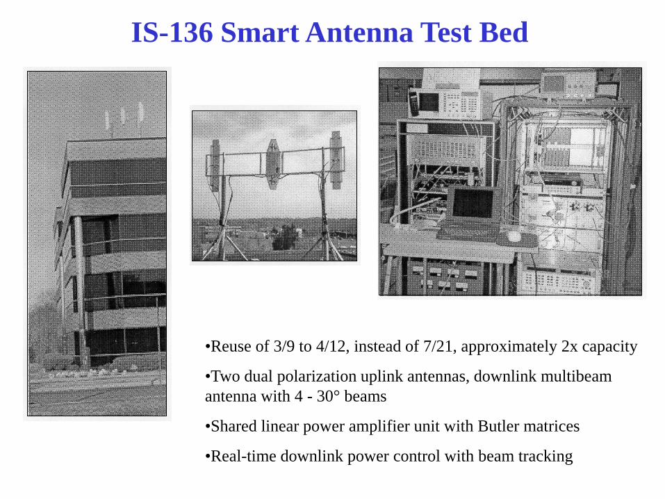
IS-136 Smart Antenna Test Bed
•Reuse of 3/9 to 4/12, instead of 7/21, approximately 2x capacity
•Two dual polarization uplink antennas, downlink multibeam
antenna with 4 - 30° beams
•Shared linear power amplifier unit with Butler matrices
•Real-time downlink power control with beam tracking

Wireless Data Terminals
Nokia 9110
3COM
Palm VII
Nokia
3G vision Sierra PCMCIA
CDPD Modem
The new
Ericsson R380
phone, which
features
wireless data
functions

WIRELESS COMPUTING
WIRELESS
GROWTH
INTERNET
GROWTH
RF & DIGITAL
TECHNOLOGY
MOBILE
SOFTWARE
- web access
- file transfer
- location services
- streaming audio
& video

data
rate
1 M
384 k
64 k
9.6 k IS-136
IS-136+
EDGE
Wideband
OFDM
Macrocellular Wireless Data Evolution
& AT&T’s Roadmap
CDPD
GSM
IS-95
GPRS
IS-95+
WCDMA
1995 2000 2005
PDC
5 M
HDR

EDGE Technology Enhanced Data-rates for Global Evolution
• Evolutionary path to 3G services for GSM and TDMA
operators
• Builds on General Packet Radio Service (GPRS) air
interface and networks
• Phase 1 (Release’99 & 2002 deployment) supports best
effort packet data at speeds up to about 384 kbps
• Phase 2 (Release’2000 & 2003 deployment) will add
Voice over IP capability

GPRS Airlink
• General Packet Radio Service (GPRS)
• Same GMSK modulation as GSM
• 4 channel coding modes
• Packet-mode supporting up to about 144 kbps
• Flexible time slot allocation (1-8)
• Radio resources shared dynamically between speech
and data services
• Independent uplink and downlink resource allocation
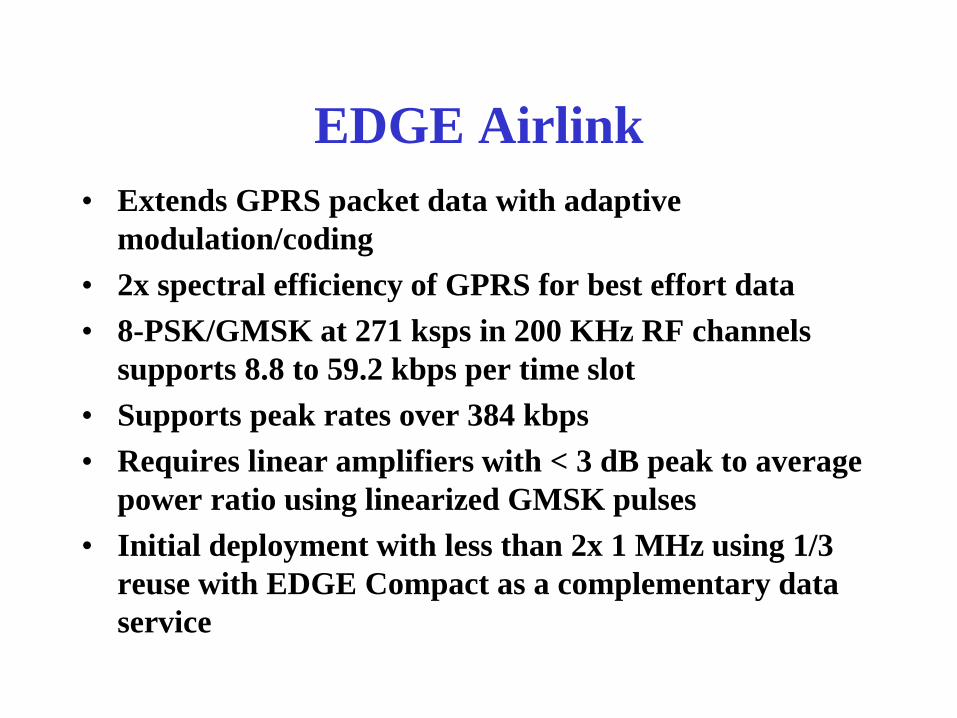
EDGE Airlink
• Extends GPRS packet data with adaptive
modulation/coding
• 2x spectral efficiency of GPRS for best effort data
• 8-PSK/GMSK at 271 ksps in 200 KHz RF channels
supports 8.8 to 59.2 kbps per time slot
• Supports peak rates over 384 kbps
• Requires linear amplifiers with < 3 dB peak to average
power ratio using linearized GMSK pulses
• Initial deployment with less than 2x 1 MHz using 1/3
reuse with EDGE Compact as a complementary data
service

GPRS Networks
• consists of packet wireless access network and IP-based
backbone
• shares mobility databases with circuit voice services
and adds new packet switching nodes (SGSN & GGSN)
• will support GPRS, EDGE & WCDMA airlinks
• provides an access to packet data networks
– Internet
– X.25
• provides services to different mobile classes ranging
from 1-slot to 8-slot capable
• radio resources shared dynamically between speech
and data services

Compact vs Classic • Classic
– 4/12 reuse
– continuous downlinks on first 12 carriers
– 2.4 MHz x2 minimum spectrum
• Compact
– 1/3 reuse in space
– frame synchronized base stations
– reuse of 4 in time for control channels
– partial loading for traffic channels
– discontinuous downlinks
– 600 KHz x2 minimum spectrum

EDGE Channel Coding and Frame Structure
464 bits
1 data block
Convolutional
Coding
Rate = 1/3
Length = 7
Puncture Interleave
Burst N
Burst N+1
Burst N+2
Burst N+3 Burst
Format
8PSK
Modulate
1392 bits 1392 bits
348 bits/
burst
348 bits 468.75 bits
156.25 symbols/slot
0 1 2 3 4 5 6 7
8 Time Slots
1 Time Slot = 576.92 µs
Tail
symbols
3
Data
symbols
58
Tail
symbols
3
Data
symbols
58
Training
symbols
26
Guard
symbols
8.25
Modulation: 8PSK, 3 bits/symbol
Symbol rate: 270.833 ksps
Payload/burst: 348 bits
Gross bit rate/time slot: 69.6 kbps - overhead = 59.2 kbps user data
20 msec frame with 4 time-slots for each of 8 bearers

EDGE Modulation, Channel Coding & Bit Rates
Scheme Modulation Maximum
rate [kb/s]
Code Rate Family
MCS-9 59.2 1.0 A
MCS-8 54.4 0.92 A
MCS-7 44.8 0.76 B
MCS-6 29.6 0.49 A
MCS-5
8PSK
22.4 0.37 B
MCS-4 17.6 1.0 C
MCS-3 14.8 0.80 A
MCS-2 11.2 0.66 B
MCS-1
GMSK
8.8 0.53 C

EDGE Link Throughput
9

EDGE Compact System Performance
0
10
20
30
40
50
60
70
80
90
100
0 10 20 30 40 50 60 70
Probability throughput < = X per timeslot
X (kb/s)
26 users/sector at 3.5 kbps average load per user
0
10
20
30
40
50
60
70
80
90
100
0 1000 2000 3000 4000 5000
Probability packet delay < = X
X (msec)
% %

0
50
100
150
200
250
300
9 18 27 36 45
single-slot
Multi-slot
Average User Throughput (kb/s)
EDGE Classic Multi-slot Gain
Ave. # of users per sector

EDGE Evolution
• Best effort IP packet data on EDGE
• Voice over IP on EDGE circuit bearers
• Network based intelligent resource assignment
• Smart antennas & adaptive antennas
• Downlink speeds at several Mbps based on wideband
OFDM and/or multiple virtual channels

0
5
10
15
20
25
30
35
40
45
50
55
Baseline Enhanced
Norm
ali
zed
voic
e ca
paci
ty
(Erl
an
g/S
ite/
MH
z)
GSM IS-136 EGPRS/GMSK/F EGPRS/8PSK/H
30 29
50
35
11
7
20
10
7.2 MHz Spectrum
* 1/3 reuse
* no shadow fading change due to mobility
*Signal-based power control is assumed for baseline EGRPS
*SINR-based power control & LI-DCA assumed for enhanced
VoIP over EDGE Bearer Performance
• Focused on GMSK full-rate & 8PSK half-rate EDGE channels with
dedicated MAC & random frequency hopping for 7.4 kbps voice coding
*This assumes 30 mph vehicle speed for micro fading
* SINR-based power control with adaptive target

Aggressive frequency re-use
High spectrum efficiency
Increased co-channel interference
Downlink Switched Beam Antenna
SIGNAL
OUTPUT
INTERFERENCE
SIGNAL
SIGNAL
OUTPUT
BEAMFORMER
WEIGHTS
Uplink Adaptive Antenna
SIGNAL
INTERFERENCE
BE
AM
FO
RM
ER
BEAM
SELECT
Smart antennas provide substantial interference
suppression for enhanced performance
Smart Antennas for EDGE • Key enhancement technique to improve system capacity and user experience
• Leverage Smart Antennas currently in development/deployment for IS-136 & GSM

EDGE Smart Antenna Processing
Dual Diversity Receiver Using DDFSE for Joint ISI
and CCI Suppression
Deinter-
leaver
Viterbi
Decoder
Soft Output
Output
Data
Receiver
Feed-forward
Filter
Symbol Timing
and Recovery
DDFSE
Equalizer
Equalizer
Training
Rx Rx Filter
Rx Rx Filter Feed-forward
Filter
• Simulation results show a 15 to 30
dBimprovement in S/I with 2 receive
antennas
• Real-time EDGE Test Bed supports
laboratory and field tests to demonstrate
improved performance
Jack Winters
Hanks Zeng
Ashutosh Dixit

EDGE 2-Branch Smart Antenna Performance Laboratory Tests
EDGE MCS-5 with Interference Suppression in a
Typical Urban Environment
Blo
ck
Err
or
Rate
Signal-to-Interference Ratio (dB)
20 dB SNR
Laboratory results show a 15 to 30 dB improvement
in S/I with 2 receive antennas

Improvement with Terminal Diversity and
Interference Suppression: User Experience
0
10
20
30
40
50
60
70
80
90
100
0 10 20 30 40 50 60 70
No Diversity
Simple
DiversityInterference
Suppression
Prob. (throughput <=X) (%)
X (kb/s)
Typical user throughput increased from 30 to 45 kbps per time-slot
Prototype Dual Antenna
Handset
External Whip
Internal Patch
Multi-cell EDGE Compact Simulation
- 1/3 reuse
- 18 users per sector
- 3.5 kbps average load per user

• spectrum - 500 MHz to 3 GHz
• 3G EDGE/WCDMA network for uplink, downlink,
control and signalling
• 4G WOFDM high speed downlink
“a wireless cable modem”
• Complement to EDGE/UMTS
• High peak data rates (up to 10 Mb/s)
in a 5 MHz channel
4G Wireless: One View

Path Loss and Fading Challenge
Delay
Spread
Rayleigh
Fading
Path
Loss
rapid fading of 20 to 30 dB
(power varies by 100 to 1000 times
in level at rates of about 100 times per second)
path loss up to
~ 150 dB
(that is a 1 followed
by 15 zeroes)
Reflected signals
arrive spread out
over 5 to 20
microsecond
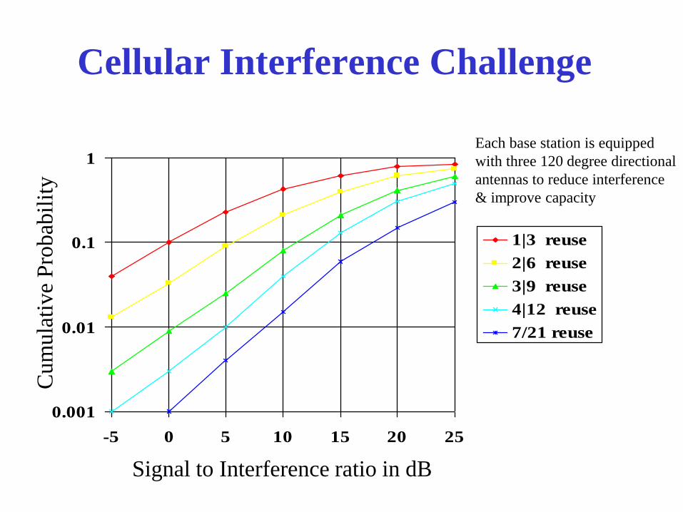
Cellular Interference Challenge
0.001
0.01
0.1
1
-5 0 5 10 15 20 25
1|3 reuse
2|6 reuse
3|9 reuse
4|12 reuse
7/21 reuse
Signal to Interference ratio in dB
Cum
ula
tive
Pro
bab
ilit
y
Each base station is equipped
with three 120 degree directional
antennas to reduce interference
& improve capacity

AT&T Labs-Research Work on 4G
• Smart antennas
• Multiple-Input-Multiple-Output Systems
• Space-Time Coding
• Dynamic Packet Assignment
• Wideband OFDM

MIMO Radio Channel Measurements
• Multiple antennas at both the base station and terminal can significantly increase data rates with sufficient multipath
• Ability to separate signals from closely spaced antennas has been demonstrated indoors and in AT&T-Lucent IS-136 field trial
• Lucent has demonstrated 26 bps/Hz in 30 kHz channel with 8 Tx and 12 Rx antennas indoors
• AT&T has performed measurements on 4 Tx by 4 Rx antenna configurations in full mobile & outdoor to indoor environments

MIMO Channel Measurement System
Transmitter
• 4 antennas mounted on a laptop
• 4 coherent 1 Watt 1900 MHz transmitters
with synchronous waveform generator
Receive System
• Dual-polarized slant 45° PCS antennas separated by
10 feet and fixed multibeam antenna with 4 - 30° beams
• 4 coherent 1900 MHz receivers with real-time baseband
processing using 4 TI TMS320C40 DSPs

MIMO Measured Channel Capacity Potential Capacity Relative to a Single Antenna System
• Capacity increase close to 4 times that of a single antenna is possible with 4 transmit and 4 receive antennas
• Capacity for pedestrians is similar to mobile users

Performance Measure
• Complex channel measurement: H = [ H ij] for the ith
transmit and jth receive antenna
• Capacity (instantaneous and averaged over 1 second)
for 4 TX by 4 RX:
C = log2(det[I + (/4)H†H]) = log2(1 + (/4)i)
where is the total signal-to-noise ratio per antenna and
i is the ith eigenvalue of H†H
• To eliminate the effect of shadow fading, the capacity is
normalized to the average capacity with a single
antenna:
Cn = log2(1 + (/4)i) / (1/16) log2(1 + Hij)

Multiple Input Multiple Output Wireless
• RX diversity - HF, terrestrial microwave, cellular….
• TX frequency offset diversity & simulcasting for paging - 70’s
• Adaptive array processing in military systems
• TX diversity - 80’s
– frequency offset (channel decoding combining)
– delay (equalizer combining)
• Optimum combining for cellular (multipath channels) - 80’s
• Space-division multiple access - 80’s & 90’s
– angle-of-arrival based
– multi-path based (supports co-location & multi-channels per user)
• MIMO - 80’s & 90’s
– Multiple spatial channels using adaptive antenna arrays
– BLAST - successive interference cancellation combined with coding
– Space-Time coding

Space-Time Coding
How do you enhance TX delay diversity ( a repetition code)?

Multiple Antennas increase System
Capacity
• MIMO (BLAST & space-time coding) techniques
increase bit rate and/or quality on a link by creating
multiple channels and/or enhancing diversity
• Switched/steered beam antennas for base stations and
interference suppression/adaptive antennas for
terminals reduce interference, increasing system
capacity

OFDM for 4G Wireless
~ 6 kHz
~ 800
tones
~ 5 MHz
• OFDM is being increasingly used in
high -speed information transmission
systems:
- European HDTV
- Digital Audio Broadcast (DAB)
- Digital Subscriber Loop (DSL)
- IEEE 802.11 Wireless LAN
5 MHz channels
~ 6 KHz tones
~ 13/26 MHz sample rate
2048 FFT size (160 usec OFDM blocks)
256/512 sample OFDM block guard time
QPSK & 16-QAM modulation adaptive modulation/coding
1 to 2 msec time-slots in 20 to 40 msec frames
Mobile OFDM parameters: ex.

OFDM Characteristics • High peak-to-average power levels
• Preservation of orthogonality in severe multi-path
• Efficient FFT based receiver structures
• Enables efficient TX and RX diversity
• Adaptive antenna arrays without joint equalization
• Support for adaptive modulation by subcarrier
• Frequency diversity
• Robust against narrow-band interference
• Efficient for simulcasting
• Variable/dynamic bandwidth
• Used for highest speed applications
• Supports dynamic packet access

OFDM Robust Channel Estimation
FFT
FFT
synch word remove
data
received
signals
IFFT FFT
.
.
.
.
.
.
.
.
.
.
.
.
. . . . . .
data
Estimator 1
Estimator 2
2-branch
maximal-ratio
combining
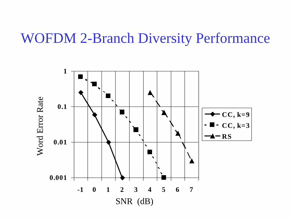
WOFDM 2-Branch Diversity Performance
0.001
0.01
0.1
1
-1 0 1 2 3 4 5 6 7
CC, k=9
CC, k=3
RS
SNR (dB)
Wo
rd E
rror
Rat
e

Spectrum Efficiency
Efficiency: IS-136 0.04; IS-95 0.07; GSM 0.04
Source: G. J. Pottie, IEEE Personal Communications, pp. 50-67, October 1995
0
0.1
0.2
0.3
0.4
0.5
0.6
0.7
0.8
0.9
1
5 7.5 10 12.5 15
Synch CDMA
Dynamic Channel
Allocation with
Power Control
Dynamic Channel
Allocation
SNR (dB)
Efficiency

Dynamic Packet Assignment
1. Mobile locks to
the STRONGEST
base
2. Mobile sends measurements
of path losses for nearby bases
to serving base
3. Serving base
forwards
measurements
to nearby bases
4. Bases assign
channels to all
packets/mobiles
5. Bases forward
channel assignment
info to nearby
bases
~ 50 % improvement in performance

Wideband OFDM Staggered Frame
Frame 20 ms
1 2 4 1 2 4 .....
Superframe 80 ms
Superframe
80 ms
Control Slots Control Slots .....
3 3
4 ms
5 Blocks 5 Blocks 5 Blocks
group A group B group C group D
16 resources in 1 msec time-slots
1B 2 B
Sync & data
20 OFDM Blocks
data
5 Blocks
2 B
data

WOFDM Performance with Dynamic
Packet Assignment & 5 MHz of Spectrum
0
20
40
60
80
100
120
0 500 1000 1500 2000 2500 3000 3500
MR, No beam-forming
IS, No beam-forming
MR, Four beams per sector
IS, Four beams per sector
Ave
. U
ser
Pa
cket
Del
ay
(mse
c)
Throughput per site (kb/s)

OFDM Experimental Program
• Baseband signal processing based on commercial off-the-shelf
DSP hardware with some custom designed components
• Sony-provided 1900 MHz transceivers
• Real-time performance measured through RF channel fading simulator
• Phase 1 parameters:
- >384 kb/s end user data rate
- 800 kHz downlink bandwidth
- GSM-derived clocks (2.166 MHz sample rate with 512 FFT)
- 3.467 kbaud
- 189 OFDM tones with 4.232 kHz tone spacing
- differential detection
- Reed-Solomon channel coding

RF A/D FFT
Demodulator Erasure
detection Decoder
Data
Intf
RF A/D FFT
OFDM receiver
“Typical Urban” channel
800 kHz

Summary: Key Features of 4G W-OFDM
• IP packet data centric
• Support for streaming, simulcasting & generic data
• Peak downlink rates of 5 to 10 Mbps
• Full macro-cellular/metropolitan coverage
• Asymmetric with 3G uplinks (EDGE)
• Variable bandwidth - 1 to 5 MHz
• Adaptive modulation/coding
• Smart/adaptive antennas supported
• MIMO/BLAST/space-time coding modes
• Frame synchronized base stations using GPS
• Network assisted dynamic packet assignment