Configurable and Scalable Turbo Decoder for 4G Wireless...
24
Configurable and Scalable Turbo Configurable and Scalable Turbo Configurable and Scalable Turbo Configurable and Scalable Turbo Decoder for 4G Wireless Decoder for 4G Wireless Decoder for 4G Wireless Decoder for 4G Wireless Receivers Receivers Receivers Receivers Yang Sun Rice University, USA Joseph R. Cavallaro Rice University, USA Yuming Zhu Texas Instruments, USA Manish Goel Texas Instruments, USA ABSTRACT The increasing requirements of high data rates and quality of service (QoS) in fourth-generation (4G) wireless communication require the implementation of practical capacity approaching codes. In this chapter, the application of Turbo coding schemes that have recently been adopted in the IEEE 802.16e WiMax standard and 3GPP Long Term Evolution (LTE) standard are reviewed. In order to process several 4G wireless standards with a common hardware module, a reconfigurable and scalable Turbo decoder architecture is presented. A parallel Turbo decoding scheme with scalable parallelism tailored to the target throughput is applied to support high data rates in 4G applications. High-level decoding parallelism is achieved by employing contention-free interleavers. A multi-banked memory structure and routing network among memories and MAP decoders are designed to operate at full speed with parallel interleavers. A new on-line address generation technique is introduced to support multiple Turbo interleaving patterns, which avoids the interleaver address memory that is typically necessary in the traditional designs. Design trade-offs in terms of area and power efficiency are analyzed for different parallelism and clock frequency goals. KEYWORDS Error Correction Codes, Turbo Codes, MAP Algorithm, BCJR Algorithm, Turbo Decoder, Interleaver, Wireless PHY, 4G Receiver, VLSI Architecture INTRODUCTION The approaching fourth-generation (4G) wireless systems are promising to support very high data rates from 100 Mbps to 1 Gbps. This consequently leads to orders of complexity increases in a 4G wireless receiver. The high performance convolutional Turbo codes are employed in many 4G wireless standards such as IEEE 802.16e WiMax and 3GPP Long Term Evolution (LTE).
Transcript of Configurable and Scalable Turbo Decoder for 4G Wireless...
Configurable and Scalable Turbo Configurable and Scalable Turbo Configurable and Scalable Turbo Configurable and Scalable Turbo
Decoder for 4G Wireless Decoder for 4G Wireless Decoder for 4G Wireless Decoder for 4G Wireless ReceiversReceiversReceiversReceivers
Yang Sun Rice University, USA Joseph R. Cavallaro Rice University, USA Yuming Zhu Texas Instruments, USA Manish Goel Texas Instruments, USA ABSTRACT The increasing requirements of high data rates and quality of service (QoS) in fourth-generation (4G) wireless communication require the implementation of practical capacity approaching codes. In this chapter, the application of Turbo coding schemes that have recently been adopted in the IEEE 802.16e WiMax standard and 3GPP Long Term Evolution (LTE) standard are reviewed. In order to process several 4G wireless standards with a common hardware module, a reconfigurable and scalable Turbo decoder architecture is presented. A parallel Turbo decoding scheme with scalable parallelism tailored to the target throughput is applied to support high data rates in 4G applications. High-level decoding parallelism is achieved by employing contention-free interleavers. A multi-banked memory structure and routing network among memories and MAP decoders are designed to operate at full speed with parallel interleavers. A new on-line address generation technique is introduced to support multiple Turbo interleaving patterns, which avoids the interleaver address memory that is typically necessary in the traditional designs. Design trade-offs in terms of area and power efficiency are analyzed for different parallelism and clock frequency goals. KEYWORDS Error Correction Codes, Turbo Codes, MAP Algorithm, BCJR Algorithm, Turbo Decoder, Interleaver, Wireless PHY, 4G Receiver, VLSI Architecture INTRODUCTION The approaching fourth-generation (4G) wireless systems are promising to support very high data rates from 100 Mbps to 1 Gbps. This consequently leads to orders of complexity increases in a 4G wireless receiver. The high performance convolutional Turbo codes are employed in many 4G wireless standards such as IEEE 802.16e WiMax and 3GPP Long Term Evolution (LTE).
A Turbo decoder is typically one of the most computation-intensive parts in a 4G wireless receiver. Increased complexity and performance requirements and the need to reduce power and area are significant challenges for Turbo decoder hardware implementation. The push for multi-mode wireless physical layer (PHY) brings additional challenges for Turbo decoder design. While programmable DSP/SIMD/VLIW processors can offer great flexibility in supporting different types of Turbo codes, they have several drawbacks notably higher power consumption and lower throughput than the ASIC solutions, which make them unsuitable for handheld devices. The commonalities between these Turbo codes in 4G wireless standards allow resources to be shared thus reducing hardware area and making more efficient use of the data path. However, there are differences in the exact Turbo decoder implementations. In order to meet high-speed multiple 4G standards, a reconfigurable and scalable Turbo decoder (or coprocessor) is necessary. From an implementation point of view, there are many aspects of Turbo codes that make them still a very hot research topic. First, the original MAP algorithm is of great complexity, so it is impractical to implement it in hardware. So the Log-MAP and Max-Log-MAP algorithms were proposed later to reduce the arithmetic complexity while still maintaining good decoding performance. The long latency of MAP decoding has prevented it from being used in the real-time systems. One effective solution is to apply a sliding window algorithm to reduce the decoding latency. The scheduling of parallel sliding windows becomes the main challenge in parallel Turbo decoder design. Second, the non-binary Turbo codes are proven to have better performance than the binary Turbo codes. An area-efficient high-radix Turbo decoder architecture poses another design challenge. Finally, the new contention-free interleaver enables a very high level of parallelism in Turbo decoding, but on the other hand it creates an obstacle for the internal memory structure. The memories need to be partitioned and managed properly to avoid memory access conflicts introduced by the interleaver.
This chapter discusses several types of Turbo coding schemes that have recently been approved in IEEE 802.16e WiMax, 3GPP LTE, and some other 3G/4G standards. It describes a high-throughput, area- and power- efficient VLSI architecture for multi-mode Turbo decoders. A multi-banked memory structure and routing network between memories and MAP decoder cores are also introduced. Simulation and implementation results are presented which show that, with the aid of a unified trellis structure, a configurable and scalable Turbo decoder architecture provides a practical solution to the requirements of flexible and high data-rate reliable transmission for 4G wireless networks. BACKGROUND The Turbo code (Berrou et al., 1993; Berrou et al., 1996) has become one of the most important research topics in coding theory since its discovery in 1993. The astounding performance of Turbo code has attracted a great deal of interest in the research activity in the area of iterative error correction codes. Due to its excellent error correction performance, many communication standards have chosen Turbo codes as the Forward Error Correction (FEC) codes, such as CDMA-2000, W-CDMA, DVB-RCS, HSDPA, UMTS, IEEE 802.16e WiMax, and 3GPP LTE. Turbo codes can be categorized into two classes: binary Turbo codes and non-binary Turbo codes. For example, Turbo codes in CDMA, HSDPA, UMTS and 3GPP LTE are binary types of Turbo codes, whereas Turbo codes in IEEE 802.16e and DVB-RCS are double-binary types of Turbo codes. Table 1 summarizes some of the Turbo codes in practice (Berrou, 2003). As we can see, there are many similarities between the Turbo codes employed in different standards. This motivates the design of a unified and flexible Turbo decoder which can support multiple standards. Without loss of generality, we will mainly focus on the Turbo codes defined in 3GPP LTE and WiMax in the following analysis. Note that these analyses can be applied to other systems directly because the encoder polynomials are same.
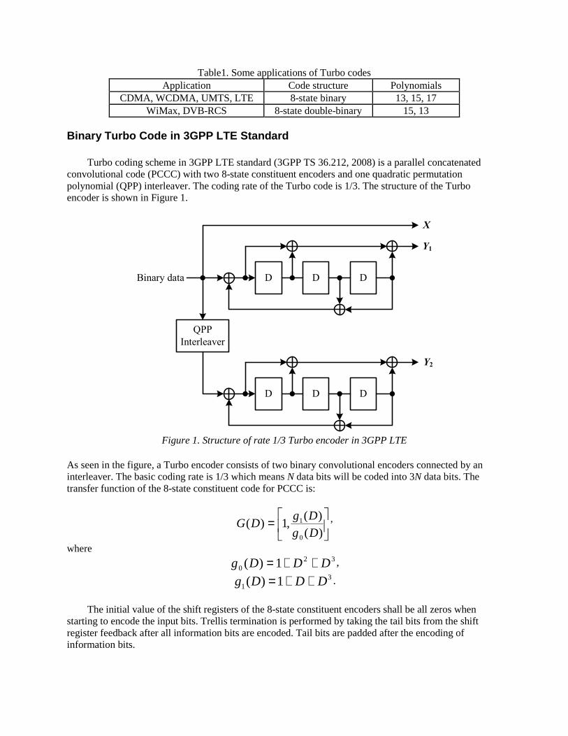
Table1. Some applications of Turbo codes Application Code structure Polynomials
CDMA, WCDMA, UMTS, LTE 8-state binary 13, 15, 17 WiMax, DVB-RCS 8-state double-binary 15, 13
Binary Turbo Code in 3GPP LTE Standard
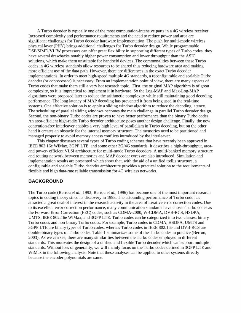
Turbo coding scheme in 3GPP LTE standard (3GPP TS 36.212, 2008) is a parallel concatenated convolutional code (PCCC) with two 8-state constituent encoders and one quadratic permutation polynomial (QPP) interleaver. The coding rate of the Turbo code is 1/3. The structure of the Turbo encoder is shown in Figure 1.
QPP
Interleaver
D D D
D D D
Binary data
X
Y1
Y2
Figure 1. Structure of rate 1/3 Turbo encoder in 3GPP LTE
As seen in the figure, a Turbo encoder consists of two binary convolutional encoders connected by an interleaver. The basic coding rate is 1/3 which means N data bits will be coded into 3N data bits. The transfer function of the 8-state constituent code for PCCC is:
=
)()(
,1)(0
1
Dg
DgDG ,
where 32
0 1)( DDDg ++= , 3
1 1)( DDDg ++= .
The initial value of the shift registers of the 8-state constituent encoders shall be all zeros when
starting to encode the input bits. Trellis termination is performed by taking the tail bits from the shift register feedback after all information bits are encoded. Tail bits are padded after the encoding of information bits.
The function of the Interleaver is to take each incoming block of N data bits and shuffle them in a pseudo-random manner. One of the new features in the 3GPP LTE Turbo encoder is its quadratic permutation polynomial (QPP) internal interleaver. We will see later that this QPP interleaver is the key component enabling parallel decoding of Turbo codes.
Double Binary Turbo Code in IEEE 802.16e WiMax Standard
The convolutional Turbo encoder for the IEEE 802.16e standard (IEEE Std 802.16, 2004) is depicted
in Figure 2. It uses a double binary circular recursive systematic convolutional code. Data couples (A, B), rather than a single bit sequence, are fed to the circular recursive systematic convolutional encoder twice, and four parity bits (Y1,W1) and (Y2, W2) are generated in the natural order and the interleaved order, respectively. The encoder polynomials are described in binary symbol notation as follows:
- For the feedback branch: 31 DD ++ ,
- For the Y parity bit: 321 DD ++ ,
- For the W parity bit: 31 D+ .
The tail-biting Trellis termination scheme is used as opposed to inserting extra tail bits. In this
termination scheme, the start state of the trellis equals to the end state of the trellis. Therefore, a pre-encoding operation has to be performed to determine the start state. This is not a complex problem because the encoding process can be performed at a much higher rate. A symbol-wise almost regular permutation (ARP) interleaver is used in the WiMax standard, which can enable parallel decoding of double binary Turbo codes.
2
1
+ D D D+ +
+
+
A
B
A
B
Y1 / Y2
W1 / W2
Switch
ARP
interleaver
Figure 2. Structure of rate 1/3 double binary Turbo encoder in IEEE 802.16e
Decoding Algorithm
The decoding algorithm employed in the Turbo decoders is the maximum a posteriori (MAP) algorithm proposed by Bahl et al. in 1974 and is also called the BCJR algorithm (Bahl et al., 1974). The high complexity and long latency of the original MAP algorithm has made high-speed VLSI implementations extremely difficult to realize. Fortunately, many simplifications have been applied to the original MAP algorithm in order to reduce the implementation complexity.
The Turbo decoding concept is functionally illustrated in Figure 3. As discussed before, the decoding is based on the MAP algorithm and is usually calculated in the log domain (Robertson et al., 1995) to avoid multiplications and divisions. During the decoding process, each soft-in soft-output (SISO) decoder receives the intrinsic log-likelihood ratios (LLRs) from the channel and the extrinsic LLRs from the other
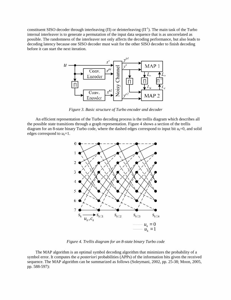
constituent SISO decoder through interleaving (П) or deinterleaving (П-1). The main task of the Turbo internal interleaver is to generate a permutation of the input data sequence that is as uncorrelated as possible. The randomness of the interleaver not only affects the decoding performance, but also leads to decoding latency because one SISO decoder must wait for the other SISO decoder to finish decoding before it can start the next iteration.
No
isy
Ch
annel
1−∏∏∏∏
Figure 3. Basic structure of Turbo encoder and decoder
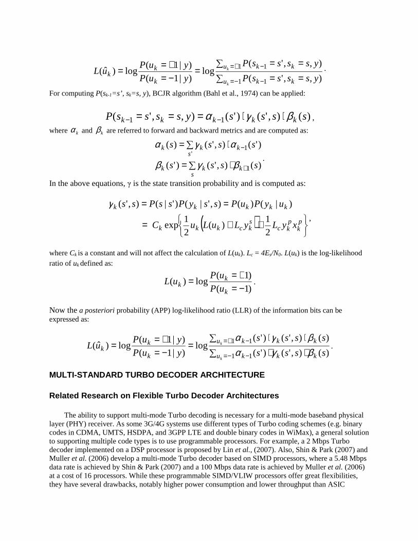
An efficient representation of the Turbo decoding process is the trellis diagram which describes all the possible state transitions through a graph representation. Figure 4 shows a section of the trellis diagram for an 8-state binary Turbo code, where the dashed edges correspond to input bit uk=0, and solid edges correspond to uk=1.
ks 1+ks 2+ks 3+ks 4+kskk cu ,
0=ku1=ku
Figure 4. Trellis diagram for an 8-state binary Turbo code
The MAP algorithm is an optimal symbol decoding algorithm that minimizes the probability of a symbol error. It computes the a posteriori probabilities (APPs) of the information bits given the received sequence. The MAP algorithm can be summarized as follows (Soleymani, 2002, pp. 25-38; Moon, 2005, pp. 588-597):
∑ ==∑ ==
=−=+==
−= −
+= −
1 1
1 1
),,'(
),,'(log
)|1(
)|1(log)ˆ(
k
k
u kk
u kk
k
kk yssssP
yssssP
yuP
yuPuL .
For computing P(sk-1=s’, sk=s, y), BCJR algorithm (Bahl et al., 1974) can be applied:
)(),'()'(),,'( 11 ssssyssssP kkkkk βγα ⋅⋅=== −− ,
where kα and kβ are referred to forward and backward metrics and are computed as:
∑ ⋅=
∑ ⋅=
+
−
skkk
skkk
ssss
ssss
)(),'()'(
)'(),'()(
1
'1
βγβ
αγα.
In the above equations, γ is the state transition probability and is computed as:
( )
++=
==
pk
pkc
skckkk
kkkkk
xyLyLuLu C
uyPuPssyPssPss
21
)(21
exp
)|()(),'|()'|(),'(γ,
where Ck is a constant and will not affect the calculation of L(uk). Lc = 4Es/N0. L(uk) is the log-likelihood ratio of uk defined as:
)1(
)1(log)(
−=+==
k
kk uP
uPuL .
Now the a posteriori probability (APP) log-likelihood ratio (LLR) of the information bits can be expressed as:
∑ ⋅⋅∑ ⋅⋅
=−=+==
−= −
+= −
1 1
1 1
)(),'()'(
)(),'()'(log
)|1(
)|1(log)ˆ(
k
k
u kkk
u kkk
k
kk ssss
ssss
yuP
yuPuL
βγαβγα
.
MULTI-STANDARD TURBO DECODER ARCHITECTURE Related Research on Flexible Turbo Decoder Architectures
The ability to support multi-mode Turbo decoding is necessary for a multi-mode baseband physical
layer (PHY) receiver. As some 3G/4G systems use different types of Turbo coding schemes (e.g. binary codes in CDMA, UMTS, HSDPA, and 3GPP LTE and double binary codes in WiMax), a general solution to supporting multiple code types is to use programmable processors. For example, a 2 Mbps Turbo decoder implemented on a DSP processor is proposed by Lin et al., (2007). Also, Shin & Park (2007) and Muller et al. (2006) develop a multi-mode Turbo decoder based on SIMD processors, where a 5.48 Mbps data rate is achieved by Shin & Park (2007) and a 100 Mbps data rate is achieved by Muller et al. (2006) at a cost of 16 processors. While these programmable SIMD/VLIW processors offer great flexibilities, they have several drawbacks, notably higher power consumption and lower throughput than ASIC
solutions. A Turbo decoder is typically one of the most computation-intensive parts in a 4G receiver, therefore it is essential to design an area and power efficient flexible Turbo decoder in ASIC.
Due to the many commonalities between different Turbo coding schemes employed in 4G wireless standards, we will present a configurable VLSI architecture for multi-standard Turbo decoding. This architecture can be reconfigured to support both simple and double binary Turbo codes with up to eight states. The memory collision problem is addressed by applying contention-free parallel interleavers. The MAP decoder, memory structure and routing network are designed to operate at full speed with the parallel interleaver. The proposed architecture meets the challenge of multi-standard Turbo decoding at very high data rates. Radix-2 Decoding of Binary Turbo Codes in the Log Domain
The original MAP algorithm is too complex for implementation in a practical system. To avoid the
complicated multiplications and solve the numerical instability issues, one can calculate the MAP algorithm in the log domain. To explain the Log-MAP decoding algorithm, we first introduce the max* function which is defined as (Robertson et al., 1995):
)1log(),max(}log{),(max ||*
baba ebaeeba −−++=+= . Consider the decoding process of a simple binary Turbo code, let sk be the trellis state at time k, then
the MAP decoder computes the LLR of the a posteriori probability (APP) of each information bit uk by
)},(),()({max
)}(),()({max)ˆ(
111
*
0
111
*
1
kkkkkkku
kkkkkkku
k
ssss
ssssu
k
k
βγα
βγα
++−
++=Λ
−−−=
−−−=
where kα and kβ are the forward and backward state metrics, respectively, and are computed as follows:
)},()({max)( 111
*
1
kkkkks
kk ssssk
−−− +=−
γαα ,
)},()({max)( 111
*
1
+++ +=+
kkkkks
kk ssssk
γββ ,
where kγ is the branch transition probability introduced earlier and is usually referred to as a branch
metric (BM). To extract the extrinsic information, )ˆ( kuΛ can be split into three terms: extrinsic
LLR )( ke uL , a priori LLR )( ka uL and systematic LLR )( skc yL as:
)()()()ˆ( skckakek yLuLuLu ++=Λ .
Radix-4 Decoding via One-Level Look-ahead Transform
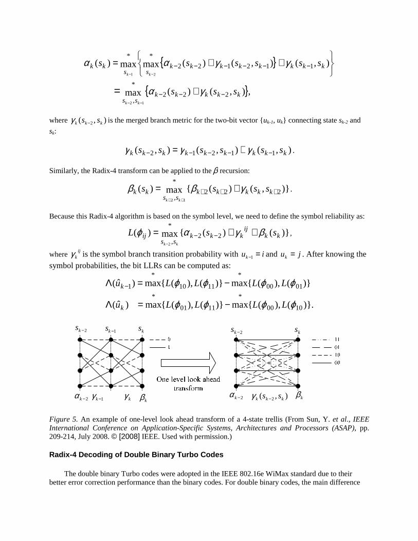
For binary Turbo codes, the trellis cycles can be reduced 50% by applying a one-level look-ahead transform (Bickerstaff et al., 2003; Zhang & Parhi, 2006) as illustrated in Figure 5. Since two stages of the trellis can be processed at each time step, this process is referred to as the Radix-4 transform. For instance, the Radix-4 α recursion can be expressed as:
{ }
{ },),()(max
),(),()(maxmax)(
222
*
,
112122
**
12
21
kkkkkss
kkkkkkkkss
kk
sss
ssssss
kk
kk
−−−
−−−−−−
+
++=
−−
−−
= γα
γγαα
where ),( 2 kkk ss −γ is the merged branch metric for the two-bit vector { uk-1, uk} connecting state sk-2 and
sk:
),(),(),( 11212 kkkkkkkkk ssssss −−−−− += γγγ .
Similarly, the Radix-4 transform can be applied to theβ recursion:
)},()({max)( 222
*
, 12
+++ +=++
kkkkkss
kk sssskk
γββ .
Because this Radix-4 algorithm is based on the symbol level, we need to define the symbol reliability as:
)}()({max)( 22
*
,2
kkij
kkkss
ij ssLkk
βγαϕ ++= −−−
,
where ij
kγ is the symbol branch transition probability with iuk =−1 and juk = . After knowing the
symbol probabilities, the bit LLRs can be computed as:
)}.(),({max)}(),({max )ˆ(
)}(),({max)}(),({max)ˆ(
1000
*
1101
*
0100
*
1110
*
1
ϕϕϕϕ
ϕϕϕϕ
LLLLu
LLLLu
k
k
−=Λ
−=Λ −
kβ1−kγ kγ
2−ks1−ks ks
2−ks ks
2−kα kβ),( 2 kkk ss −γ2−kα
Figure 5. An example of one-level look ahead transform of a 4-state trellis (From Sun, Y. et al., IEEE International Conference on Application-Specific Systems, Architectures and Processors (ASAP), pp. 209-214, July 2008. © [2008] IEEE. Used with permission.) Radix-4 Decoding of Double Binary Turbo Codes
The double binary Turbo codes were adopted in the IEEE 802.16e WiMax standard due to their better error correction performance than the binary codes. For double binary codes, the main difference
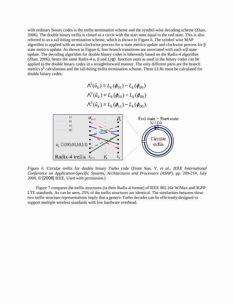
with ordinary binary codes is the trellis termination scheme and the symbol-wise decoding scheme (Zhan, 2006). The double binary trellis is closed as a circle with the start state equal to the end state. This is also referred to as a tail-biting termination scheme, which is shown in Figure 6. The symbol wise MAP algorithm is applied with an anti-clockwise process for α state metrics update and clockwise process for β state metrics update. As shown in Figure 6, four branch transitions are associated with each α/β state update. The decoding algorithm for double binary codes is inherently based on the Radix-4 algorithm (Zhan, 2006), hence the same Radix-4 α, β and L(φ) function units as used in the binary codes can be applied to the double binary codes in a straightforward manner. The only different parts are the branch metrics γij calculations and the tail-biting trellis termination scheme. Three LLRs must be calculated for double binary codes:
).()()ˆ(
)()()ˆ(
)()()ˆ(
00113
00102
00011
ϕϕ
ϕϕ
ϕϕ
kkk
kkk
kkk
LLu
LLu
LLu
−=Λ
−=Λ
−=Λ
1−kαkβ
1−ks kγ ks
}11,10,01,00{∈ku
Figure 6. Circular trellis for double binary Turbo code (From Sun, Y. et al., IEEE International Conference on Application-Specific Systems, Architectures and Processors (ASAP), pp. 209-214, July 2008. © [2008] IEEE. Used with permission.)
Figure 7 compares the trellis structures (in their Radix-4 format) of IEEE 802.16e WiMax and 3GPP LTE standards. As can be seen, 25% of the trellis structures are identical. The similarities between these two trellis structure representations imply that a generic Turbo decoder can be efficiently designed to support multiple wireless standards with low hardware overhead.
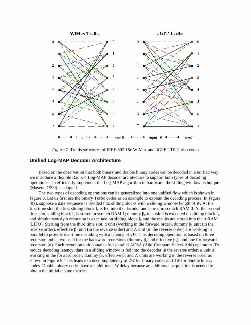
Figure 7. Trellis structures of IEEE 802.16e WiMax and 3GPP LTE Turbo codes Unified Log-MAP Decoder Architecture
Based on the observation that both binary and double binary codes can be decoded in a unified way, we introduce a flexible Radix-4 Log-MAP decoder architecture to support both types of decoding operations. To efficiently implement the Log-MAP algorithm in hardware, the sliding window technique (Masera, 1999) is adopted.
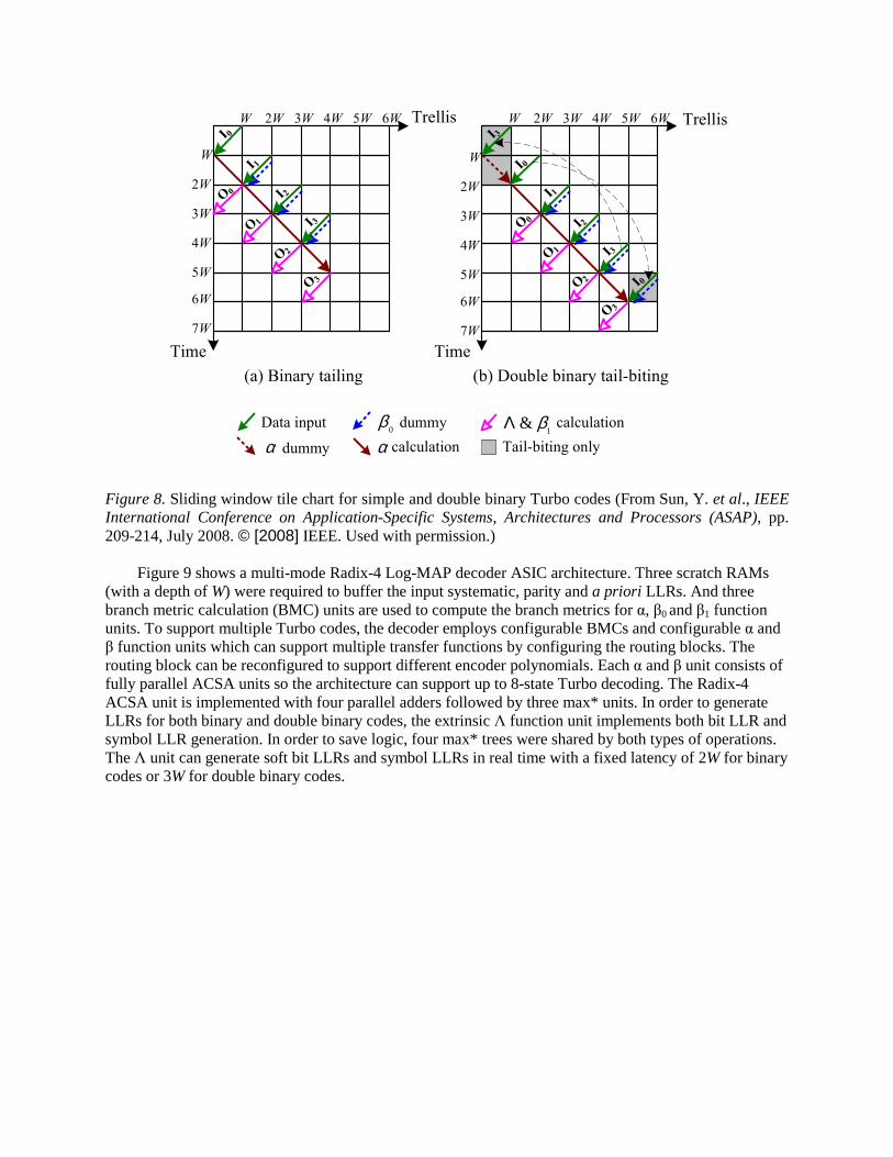
The two types of decoding operations can be generalized into one unified flow which is shown in Figure 8. Let us first use the binary Turbo codes as an example to explain the decoding process. In Figure 8(a), suppose a data sequence is divided into sliding blocks with a sliding window length of W. At the first time slot, the first sliding block I0 is fed into the decoder and stored in scratch RAM 0. At the second time slot, sliding block I1 is stored in scratch RAM 1; dummy β0 recursion is executed on sliding block I1; and simultaneously α recursion is executed on sliding block I0 and the results are stored into the α-RAM (LIFO). Starting from the third time slot, α unit (working in the forward order), dummy β0 unit (in the reverse order), effective β1 unit (in the reverse order) and Λ unit (in the reverse order) are working in parallel to provide real-time decoding with a latency of 2W. This decoding operation is based on three recursion units, two used for the backward recursions (dummy β0 and effective β1), and one for forward recursion (α). Each recursion unit contains full-parallel ACSA (Add-Compare-Select-Add) operators. To reduce decoding latency, data in a sliding window is fed into the decoder in the reverse order; α unit is working in the forward order; dummy β0, effective β1 and Λ units are working in the reverse order as shown in Figure 8. This leads to a decoding latency of 2W for binary codes and 3W for double binary codes. Double binary codes have an additional W delay because an additional acquisition is needed to obtain the initial α state metrics.
Trellis
Time
W 2W 3W 4W 5W
W
2W
3W
4W
5W
6W
W
2W
3W
4W
5W
6W
Time
(a) Binary tailing (b) Double binary tail-biting
0β Data input
αdummy calculation
dummy
α Tail-biting only
7W
6W
7W
1& βΛ calculation
I 0
I 1
I 3
I 3
I 0
I 0
I 3
I 1I 2
I 2
O 0
O 1
O 3
O 2
O 0
O 1
O 3
O 2
W 2W 3W 4W 5W 6WTrellis
Figure 8. Sliding window tile chart for simple and double binary Turbo codes (From Sun, Y. et al., IEEE International Conference on Application-Specific Systems, Architectures and Processors (ASAP), pp. 209-214, July 2008. © [2008] IEEE. Used with permission.)
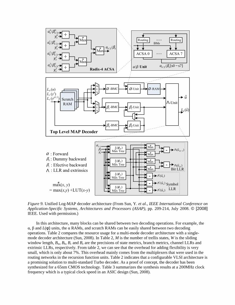
Figure 9 shows a multi-mode Radix-4 Log-MAP decoder ASIC architecture. Three scratch RAMs (with a depth of W) were required to buffer the input systematic, parity and a priori LLRs. And three branch metric calculation (BMC) units are used to compute the branch metrics for α, β0 and β1 function units. To support multiple Turbo codes, the decoder employs configurable BMCs and configurable α and β function units which can support multiple transfer functions by configuring the routing blocks. The routing block can be reconfigured to support different encoder polynomials. Each α and β unit consists of fully parallel ACSA units so the architecture can support up to 8-state Turbo decoding. The Radix-4 ACSA unit is implemented with four parallel adders followed by three max* units. In order to generate LLRs for both binary and double binary codes, the extrinsic Λ function unit implements both bit LLR and symbol LLR generation. In order to save logic, four max* trees were shared by both types of operations. The Λ unit can generate soft bit LLRs and symbol LLRs in real time with a fixed latency of 2W for binary codes or 3W for double binary codes.
Scratch
RAM
α -BMC
1β -BMC
-BMC
α-Unit
1β -Unit
-Unit
α -RAM
Λ-Unit
u
0β
Top Level MAP Decoder
M
U
X
M
U
X
0β
Lc (ys)
Lc (yp1,2)
La (u)
)( 00ϕLMax Tree
)( 01ϕL
)( 10ϕL
)( 11ϕL
- )ˆ( 12 −Λ ku
)ˆ( 2kuΛ
-
-
-
)ˆ(1kuΛ
)ˆ(2kuΛ
)ˆ(3kuΛ
Bit LLR
Symbol
LLR
*
Max Tree*
Max Tree*
Max Tree*
1−kαkβkγ
-
Max*
Max*
Max*
Max*
ACSA 0 ACSA 7
Routing Routing
. . .
. . .BMs
+
01
0/ +kka β0kγ
+1kγ
+2kγ
+3kγ
Max*
11
1/ +kka β
21
2/ +kka β
31
3/ +kka β
kka β/1+
s7][s0/1 −+ kka βUnitRadix-4 ACSA
β/aMax
*
Max*
max(x, y)
= max(x,y) +LUT(x-y)
*
0β : Dummy backward
: Efective backward1βΛ : LLR and extrinsics
α : Forward
)ˆ(uLe
Figure 9. Unified Log-MAP decoder architecture (From Sun, Y. et al., IEEE International Conference on Application-Specific Systems, Architectures and Processors (ASAP), pp. 209-214, July 2008. © [2008] IEEE. Used with permission.)
In this architecture, many blocks can be shared between two decoding operations. For example, the α, β and L(φ) units, the α RAMs, and scratch RAMs can be easily shared between two decoding operations. Table 2 compares the resource usage for a multi-mode decoder architecture with a single-mode decoder architecture (Sun, 2008). In Table 2, M is the number of trellis states, W is the sliding window length, Bm, Bb, Bc and Be are the precisions of state metrics, branch metrics, channel LLRs and extrinsic LLRs, respectively. From table 2, we can see that the overhead for adding flexibility is very small, which is only about 7%. This overhead mainly comes from the multiplexers that were used in the routing networks in the recursion function units. Table 2 indicates that a configurable VLSI architecture is a promising solution to multi-standard Turbo decoder. As a proof of concept, the decoder has been synthesized for a 65nm CMOS technology. Table 3 summarizes the synthesis results at a 200MHz clock frequency which is a typical clock speed in an ASIC design (Sun, 2008).
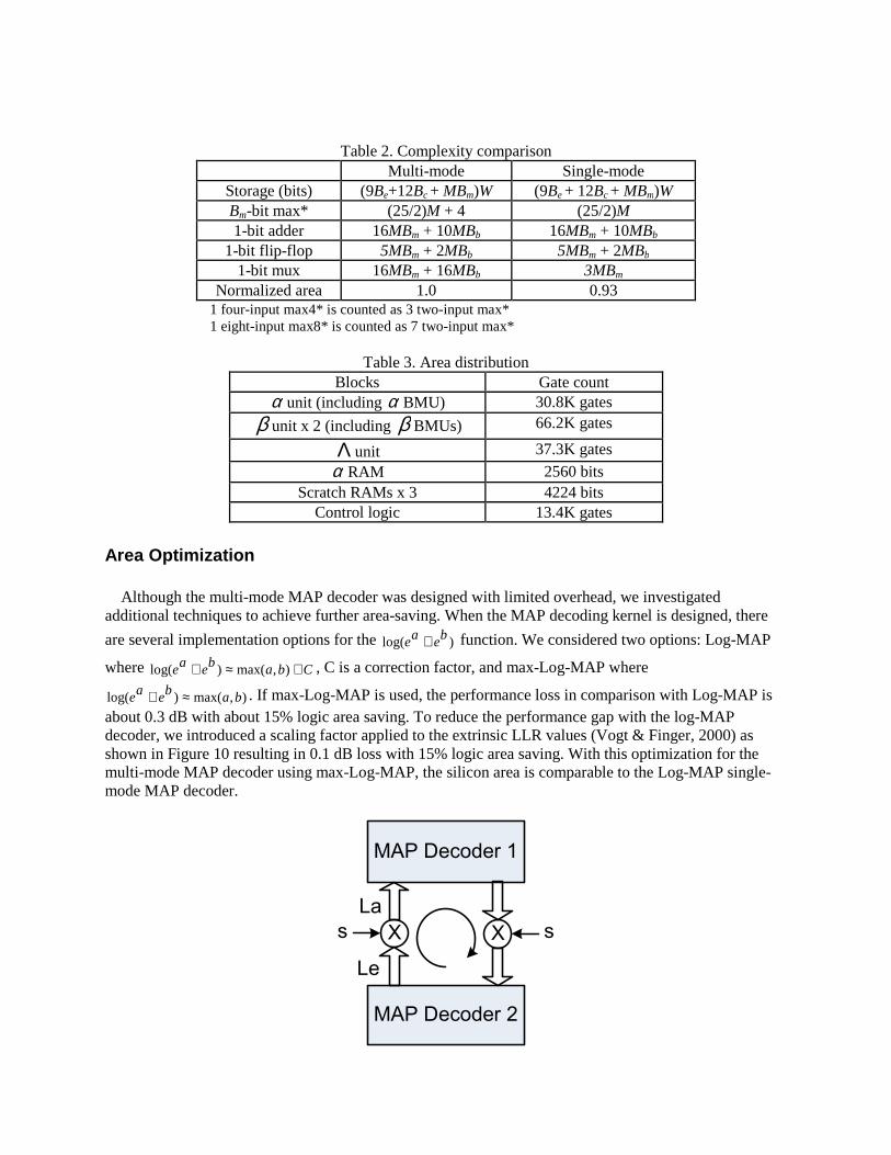
Table 2. Complexity comparison Multi-mode Single-mode
Storage (bits) (9Be+12Bc + MBm)W (9Be + 12Bc + MBm)W Bm-bit max* (25/2)M + 4 (25/2)M 1-bit adder 16MBm + 10MBb 16MBm + 10MBb
1-bit flip-flop 5MBm + 2MBb 5MBm + 2MBb 1-bit mux 16MBm + 16MBb 3MBm
Normalized area 1.0 0.93 1 four-input max4* is counted as 3 two-input max* 1 eight-input max8* is counted as 7 two-input max*
Table 3. Area distribution Blocks Gate count
α unit (including α BMU) 30.8K gates
β unit x 2 (including β BMUs) 66.2K gates
Λ unit 37.3K gates
α RAM 2560 bits Scratch RAMs x 3 4224 bits
Control logic 13.4K gates Area Optimization
Although the multi-mode MAP decoder was designed with limited overhead, we investigated
additional techniques to achieve further area-saving. When the MAP decoding kernel is designed, there
are several implementation options for the )log( beae + function. We considered two options: Log-MAP
where Cbabeae +≈+ ),max()log( , C is a correction factor, and max-Log-MAP where
),max()log( babeae ≈+ . If max-Log-MAP is used, the performance loss in comparison with Log-MAP is about 0.3 dB with about 15% logic area saving. To reduce the performance gap with the log-MAP decoder, we introduced a scaling factor applied to the extrinsic LLR values (Vogt & Finger, 2000) as shown in Figure 10 resulting in 0.1 dB loss with 15% logic area saving. With this optimization for the multi-mode MAP decoder using max-Log-MAP, the silicon area is comparable to the Log-MAP single-mode MAP decoder.
MAP Decoder 1
MAP Decoder 2
Le
Xs
La
X s
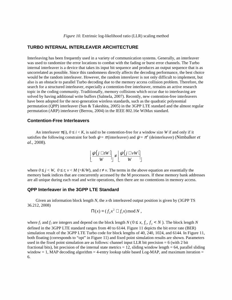
Figure 10. Extrinsic log-likelihood ratio (LLR) scaling method
TURBO INTERNAL INTERLEAVER ARCHITECTURE Interleaving has been frequently used in a variety of communication systems. Generally, an interleaver was used to randomize the error locations to combat with the fading or burst error channels. The Turbo internal interleaver is a device that takes its input bit sequence and produces an output sequence that is as uncorrelated as possible. Since this randomness directly affects the decoding performance, the best choice would be the random interleaver. However, the random interelaver is not only difficult to implement, but also is an obstacle to parallel Turbo decoding due to the memory access collision problem. Therefore, the search for a structured interleaver, especially a contention-free interleaver, remains an active research topic in the coding community. Traditionally, memory collisions which occur due to interleaving are solved by having additional write buffers (Salmela, 2007). Recently, new contention-free interleavers have been adopted for the next-generation wireless standards, such as the quadratic polynomial permutation (QPP) interleaver (Sun & Takeshita, 2005) in the 3GPP LTE standard and the almost regular permutation (ARP) interleaver (Berrou, 2004) in the IEEE 802.16e WiMax standard. Contention-Free Interleavers
An interleaver π(i), 0 ≤ i < K, is said to be contention-free for a window size W if and only if it satisfies the following constraint for both ψ = π (interleaver) and ψ = π-1 (deinterleaver) (Nimbalker et al., 2008).
( ) ( )
+≠
+W
vWj
W
tWj ψψ
where 0 ≤ j < W, 0 ≤ t; v < M (=K/W), and t ≠ v. The terms in the above equation are essentially the memory bank indices that are concurrently accessed by the M processors. If these memory bank addresses are all unique during each read and write operations, then there are no contentions in memory access. QPP Interleaver in the 3GPP LTE Standard
Given an information block length N, the x-th interleaved output position is given by (3GPP TS 36.212, 2008)
Nxfxfx mod)()( 12
2 +=Π ,
where f1 and f2 are integers and depend on the block length N ( Nffx <≤ 21,,0 ). The block length N defined in the 3GPP LTE standard ranges from 40 to 6144. Figure 11 depicts the bit error rate (BER) simulation result of the 3GPP LTE Turbo code for block lengths of 40, 240, 1024, and 6144. In Figure 11, both floating (corresponds to “opt” in Figure 11) and fixed point simulation results are shown. Parameters used in the fixed point simulation are as follows: channel input LLR bit precision = 6 (with 2 bit fractional bits), bit precision of the internal state metrics = 12, sliding window length = 64, parallel sliding window = 1, MAP decoding algorithm = 4-entry lookup table based Log-MAP, and maximum iteration = 6.
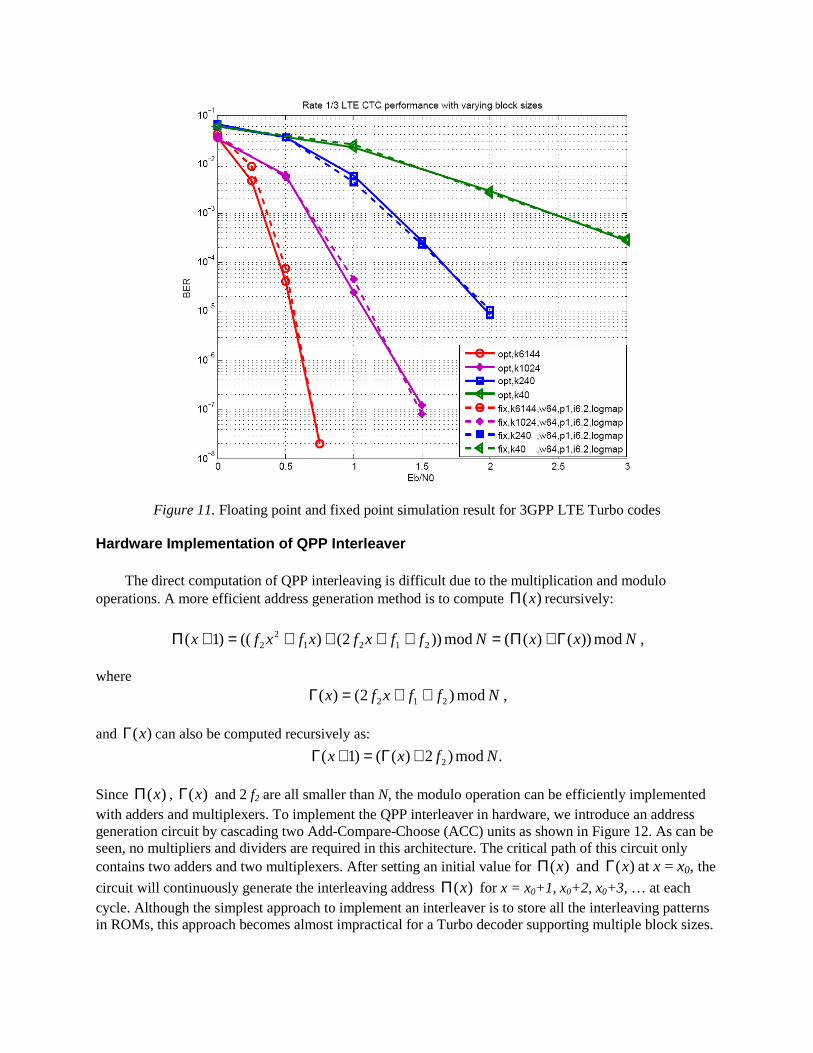
Figure 11. Floating point and fixed point simulation result for 3GPP LTE Turbo codes Hardware Implementation of QPP Interleaver
The direct computation of QPP interleaving is difficult due to the multiplication and modulo operations. A more efficient address generation method is to compute )(xΠ recursively:
NxxNffxfxfxfx mod))()((mod))2()(()1( 21212
2 Γ+Π=++++=+Π ,
where Nffxfx mod)2()( 212 ++=Γ ,
and )(xΓ can also be computed recursively as:
.mod)2)(()1( 2 Nfxx +Γ=+Γ
Since )(xΠ , )(xΓ and 2 f2 are all smaller than N, the modulo operation can be efficiently implemented with adders and multiplexers. To implement the QPP interleaver in hardware, we introduce an address generation circuit by cascading two Add-Compare-Choose (ACC) units as shown in Figure 12. As can be seen, no multipliers and dividers are required in this architecture. The critical path of this circuit only contains two adders and two multiplexers. After setting an initial value for )(xΠ and )(xΓ at x = x0, the
circuit will continuously generate the interleaving address )(xΠ for x = x0+1, x0+2, x0+3, … at each cycle. Although the simplest approach to implement an interleaver is to store all the interleaving patterns in ROMs, this approach becomes almost impractical for a Turbo decoder supporting multiple block sizes.
For instance, the 3GPP LTE has defined 188 different Turbo code sizes, which makes the ROM based interleaver implementation very inefficient.
+
+
Figure 12. QPP interleaver architecture (From Sun, Y. et al., IEEE International Conference on Application-Specific Systems, Architectures and Processors (ASAP), pp. 209-214, July 2008. © [2008] IEEE. Used with permission.) ARP Interleaver in IEEE 802.16e WiMax Standard
The interleaver adopted by the WiMax standard is called the almost regular permutation (ARP) interleaver which is also contention-free. The ARP interleaver employs a two-step interleaving process (IEEE Std 802.16, 2004). The first step switches the alternate couples as
],[],[ xxxx BAAB = , if x mod 2 = 1.
In the second step, the ARP interleaver computes
=+++=++
=+++=+
=Π
34mod,2/1
24mod,1
14mod,2/1
04mod,1
)(
30
20
10
0
xifPNxP
xifPxP
xifPNxP
xifxP
x ,
where parameters P0, P1, P2 and P3 are constants and depend on N. Hardware Implementation of ARP Interleaver
The ARP interleaver can be also computed recursively. What is more interesting is that the ARP interleaver can be implemented in a similar manner as the QPP interleaver by reusing the same two ACC
units, as shown in Figure 13. Let xPx 0)( =λ , Q0=1, Q1=1+N/2+P1, Q2=1+P2, Q3=1+N/2+P3.
After setting an initial value for )( 0xx =λ , this circuit will then continuously generate the interleaving
address )(xΠ for x = x0+1, x0+2, x0+3, … at each clock cycle. If we compare these two circuits shown in Figure 12 and Figure 13, both interleavers have the same
logic structure. The differences between these two circuits are the initial values for the ACC units. As can be seen, this unified architecture only requires a few adders and multiplexers which leads to very low
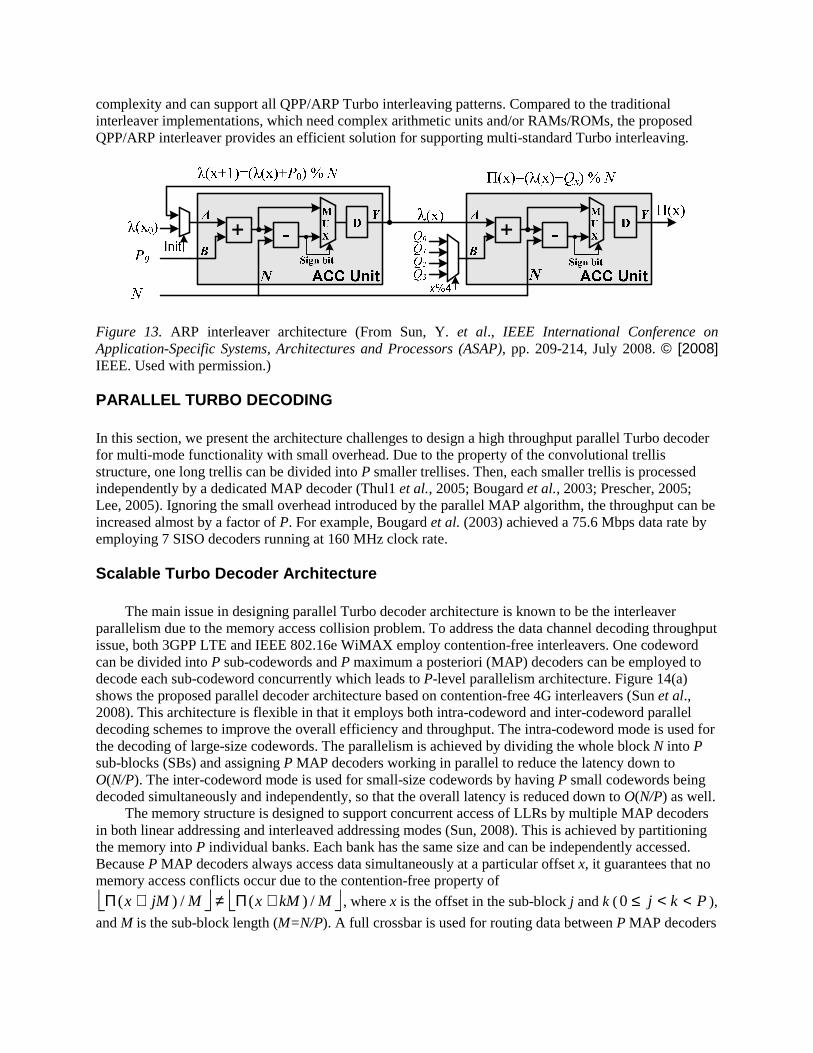
complexity and can support all QPP/ARP Turbo interleaving patterns. Compared to the traditional interleaver implementations, which need complex arithmetic units and/or RAMs/ROMs, the proposed QPP/ARP interleaver provides an efficient solution for supporting multi-standard Turbo interleaving.
++
Figure 13. ARP interleaver architecture (From Sun, Y. et al., IEEE International Conference on Application-Specific Systems, Architectures and Processors (ASAP), pp. 209-214, July 2008. © [2008] IEEE. Used with permission.) PARALLEL TURBO DECODING In this section, we present the architecture challenges to design a high throughput parallel Turbo decoder for multi-mode functionality with small overhead. Due to the property of the convolutional trellis structure, one long trellis can be divided into P smaller trellises. Then, each smaller trellis is processed independently by a dedicated MAP decoder (Thul1 et al., 2005; Bougard et al., 2003; Prescher, 2005; Lee, 2005). Ignoring the small overhead introduced by the parallel MAP algorithm, the throughput can be increased almost by a factor of P. For example, Bougard et al. (2003) achieved a 75.6 Mbps data rate by employing 7 SISO decoders running at 160 MHz clock rate. Scalable Turbo Decoder Architecture
The main issue in designing parallel Turbo decoder architecture is known to be the interleaver parallelism due to the memory access collision problem. To address the data channel decoding throughput issue, both 3GPP LTE and IEEE 802.16e WiMAX employ contention-free interleavers. One codeword can be divided into P sub-codewords and P maximum a posteriori (MAP) decoders can be employed to decode each sub-codeword concurrently which leads to P-level parallelism architecture. Figure 14(a) shows the proposed parallel decoder architecture based on contention-free 4G interleavers (Sun et al., 2008). This architecture is flexible in that it employs both intra-codeword and inter-codeword parallel decoding schemes to improve the overall efficiency and throughput. The intra-codeword mode is used for the decoding of large-size codewords. The parallelism is achieved by dividing the whole block N into P sub-blocks (SBs) and assigning P MAP decoders working in parallel to reduce the latency down to O(N/P). The inter-codeword mode is used for small-size codewords by having P small codewords being decoded simultaneously and independently, so that the overall latency is reduced down to O(N/P) as well.
The memory structure is designed to support concurrent access of LLRs by multiple MAP decoders in both linear addressing and interleaved addressing modes (Sun, 2008). This is achieved by partitioning the memory into P individual banks. Each bank has the same size and can be independently accessed. Because P MAP decoders always access data simultaneously at a particular offset x, it guarantees that no memory access conflicts occur due to the contention-free property of
MkMxMjMx /)(/)( +Π≠+Π , where x is the offset in the sub-block j and k ( Pkj <<≤0 ),
and M is the sub-block length (M=N/P). A full crossbar is used for routing data between P MAP decoders
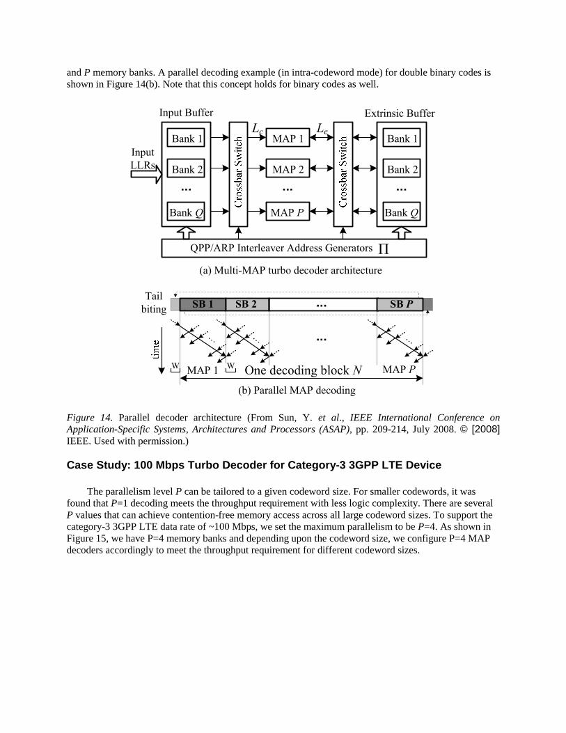
and P memory banks. A parallel decoding example (in intra-codeword mode) for double binary codes is shown in Figure 14(b). Note that this concept holds for binary codes as well.
... ...
Extrinsic Buffer
MAP 1
Bank 2
Bank Q
MAP 2
MAP P
Bank 1
...
Input Buffer
Bank 2
Bank Q
Bank 1
QPP/ARP Interleaver Address Generators П
Lc Le
Input
LLRs
...Tail
bitingSB 1 SB 2 SB P
(a) Multi-MAP turbo decoder architecture
(b) Parallel MAP decoding
...
One decoding block NWMAP 1 MAP PW
. . .. . . . . .
Figure 14. Parallel decoder architecture (From Sun, Y. et al., IEEE International Conference on Application-Specific Systems, Architectures and Processors (ASAP), pp. 209-214, July 2008. © [2008] IEEE. Used with permission.) Case Study: 100 Mbps Turbo Decoder for Category-3 3GPP LTE Device
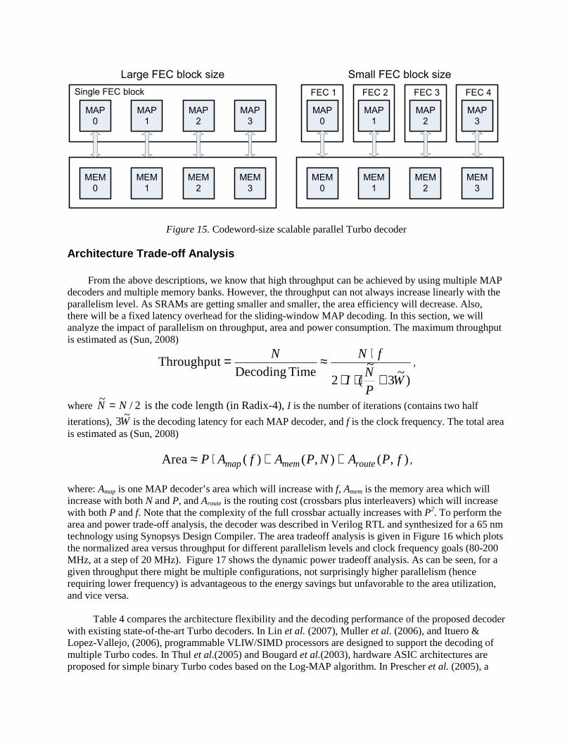
The parallelism level P can be tailored to a given codeword size. For smaller codewords, it was found that P=1 decoding meets the throughput requirement with less logic complexity. There are several P values that can achieve contention-free memory access across all large codeword sizes. To support the category-3 3GPP LTE data rate of ~100 Mbps, we set the maximum parallelism to be P=4. As shown in Figure 15, we have P=4 memory banks and depending upon the codeword size, we configure P=4 MAP decoders accordingly to meet the throughput requirement for different codeword sizes.
MAP
0
MAP
1
MAP
2
MAP
3
MEM
0
MEM
1
MEM
2
MEM
3
Large FEC block size
Single FEC block
MAP
0
MAP
1
MAP
2
MAP
3
MEM
0
MEM
1
MEM
2
MEM
3
Small FEC block size
FEC 1 FEC 2 FEC 3 FEC 4
Figure 15. Codeword-size scalable parallel Turbo decoder Architecture Trade-off Analysis
From the above descriptions, we know that high throughput can be achieved by using multiple MAP decoders and multiple memory banks. However, the throughput can not always increase linearly with the parallelism level. As SRAMs are getting smaller and smaller, the area efficiency will decrease. Also, there will be a fixed latency overhead for the sliding-window MAP decoding. In this section, we will analyze the impact of parallelism on throughput, area and power consumption. The maximum throughput is estimated as (Sun, 2008)
)~
3~
(2Time Decoding
Throughput
WP
NI
fNN
+⋅⋅
⋅≈= ,
where 2/~
NN = is the code length (in Radix-4), I is the number of iterations (contains two half
iterations), W~
3 is the decoding latency for each MAP decoder, and f is the clock frequency. The total area is estimated as (Sun, 2008)
),(),()(Area fPANPAfAP routememmap ++⋅≈ ,
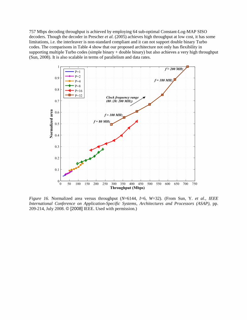
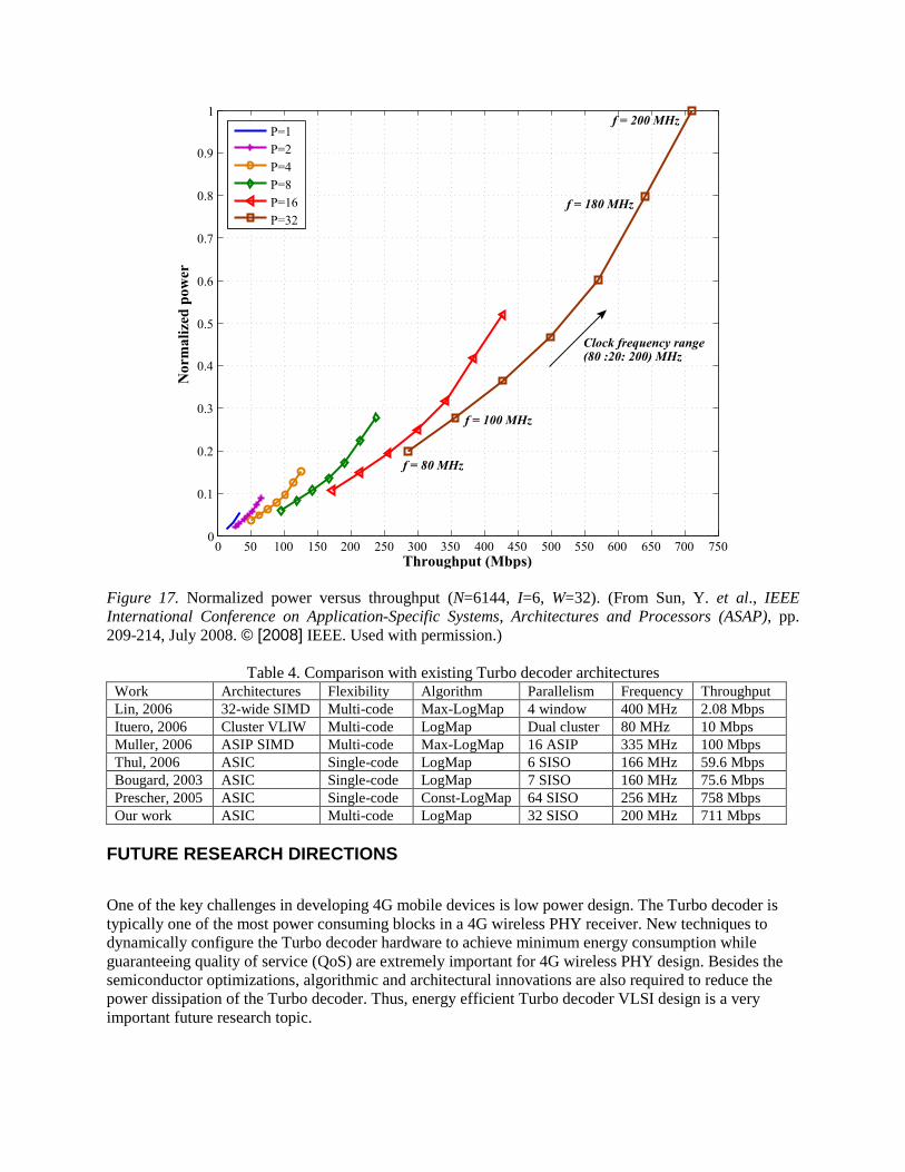
where: Amap is one MAP decoder’s area which will increase with f, Amem is the memory area which will increase with both N and P, and Aroute is the routing cost (crossbars plus interleavers) which will increase with both P and f. Note that the complexity of the full crossbar actually increases with P2. To perform the area and power trade-off analysis, the decoder was described in Verilog RTL and synthesized for a 65 nm technology using Synopsys Design Compiler. The area tradeoff analysis is given in Figure 16 which plots the normalized area versus throughput for different parallelism levels and clock frequency goals (80-200 MHz, at a step of 20 MHz). Figure 17 shows the dynamic power tradeoff analysis. As can be seen, for a given throughput there might be multiple configurations, not surprisingly higher parallelism (hence requiring lower frequency) is advantageous to the energy savings but unfavorable to the area utilization, and vice versa.
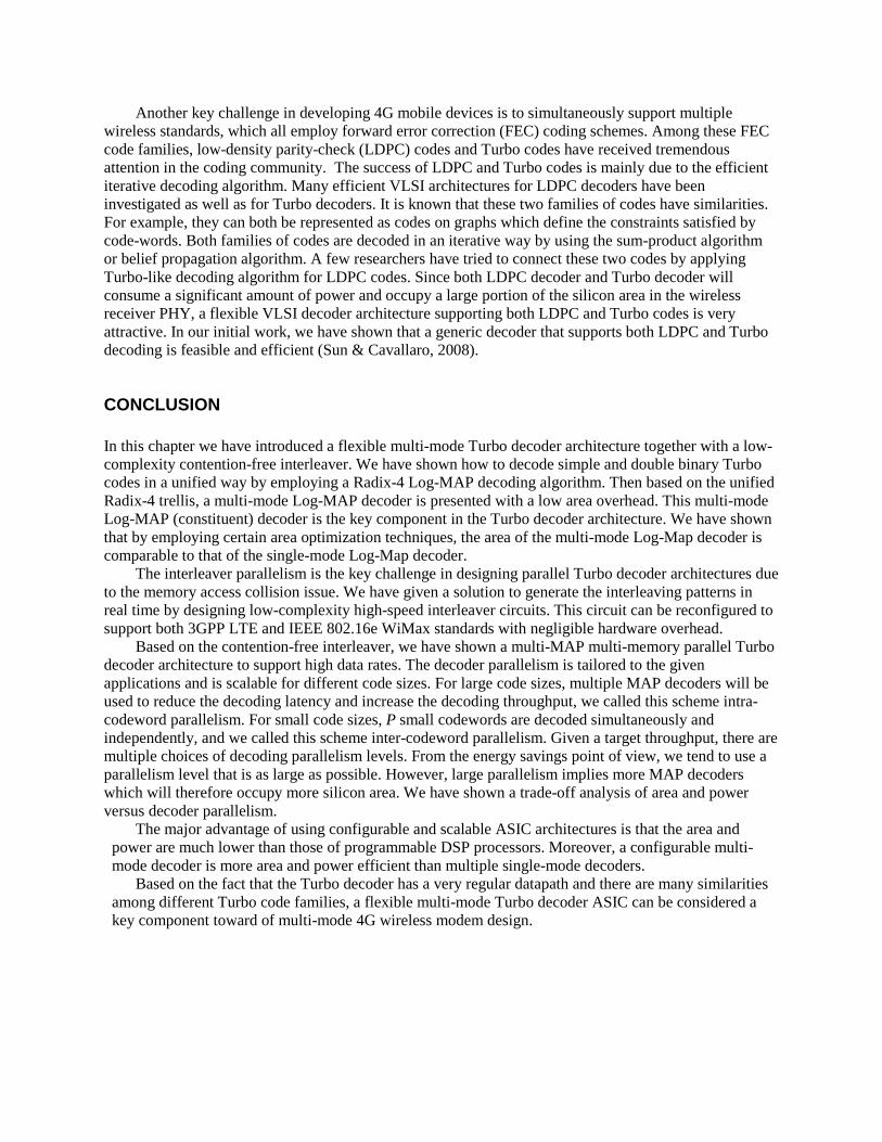
Table 4 compares the architecture flexibility and the decoding performance of the proposed decoder with existing state-of-the-art Turbo decoders. In Lin et al. (2007), Muller et al. (2006), and Ituero & Lopez-Vallejo, (2006), programmable VLIW/SIMD processors are designed to support the decoding of multiple Turbo codes. In Thul et al.(2005) and Bougard et al.(2003), hardware ASIC architectures are proposed for simple binary Turbo codes based on the Log-MAP algorithm. In Prescher et al. (2005), a
757 Mbps decoding throughput is achieved by employing 64 sub-optimal Constant-Log-MAP SISO decoders. Though the decoder in Prescher et al. (2005) achieves high throughput at low cost, it has some limitations, i.e. the interleaver is non-standard compliant and it can not support double binary Turbo codes. The comparisons in Table 4 show that our proposed architecture not only has flexibility in supporting multiple Turbo codes (simple binary + double binary) but also achieves a very high throughput (Sun, 2008). It is also scalable in terms of parallelism and data rates.
0 50 100 150 200 250 300 350 400 450 500 550 600 650 700 7500
0.1
0.2
0.3
0.4
0.5
0.6
0.7
0.8
0.9
1
Throughput (Mbps)
No
rmali
zed
are
a
P=1
P=2
P=4
P=8
P=16
P=32
f = 200 MHz
f = 80 MHz
Clock frequency range(80 :20: 200 MHz)
f = 100 MHz
f = 180 MHz
Figure 16. Normalized area versus throughput (N=6144, I=6, W=32). (From Sun, Y. et al., IEEE International Conference on Application-Specific Systems, Architectures and Processors (ASAP), pp. 209-214, July 2008. © [2008] IEEE. Used with permission.)
0 50 100 150 200 250 300 350 400 450 500 550 600 650 700 7500
0.1
0.2
0.3
0.4
0.5
0.6
0.7
0.8
0.9
1
Throughput (Mbps)
Norm
ali
zed
pow
er
P=1
P=2
P=4
P=8
P=16
P=32
f = 80 MHz
f = 200 MHz
Clock frequency range(80 :20: 200) MHz
f = 100 MHz
f = 180 MHz
Figure 17. Normalized power versus throughput (N=6144, I=6, W=32). (From Sun, Y. et al., IEEE International Conference on Application-Specific Systems, Architectures and Processors (ASAP), pp. 209-214, July 2008. © [2008] IEEE. Used with permission.)
Table 4. Comparison with existing Turbo decoder architectures Work Architectures Flexibility Algorithm Parallelism Frequency Throughput Lin, 2006 32-wide SIMD Multi-code Max-LogMap 4 window 400 MHz 2.08 Mbps Ituero, 2006 Cluster VLIW Multi-code LogMap Dual cluster 80 MHz 10 Mbps Muller, 2006 ASIP SIMD Multi-code Max-LogMap 16 ASIP 335 MHz 100 Mbps Thul, 2006 ASIC Single-code LogMap 6 SISO 166 MHz 59.6 Mbps Bougard, 2003 ASIC Single-code LogMap 7 SISO 160 MHz 75.6 Mbps Prescher, 2005 ASIC Single-code Const-LogMap 64 SISO 256 MHz 758 Mbps Our work ASIC Multi-code LogMap 32 SISO 200 MHz 711 Mbps
FUTURE RESEARCH DIRECTIONS
One of the key challenges in developing 4G mobile devices is low power design. The Turbo decoder is typically one of the most power consuming blocks in a 4G wireless PHY receiver. New techniques to dynamically configure the Turbo decoder hardware to achieve minimum energy consumption while guaranteeing quality of service (QoS) are extremely important for 4G wireless PHY design. Besides the semiconductor optimizations, algorithmic and architectural innovations are also required to reduce the power dissipation of the Turbo decoder. Thus, energy efficient Turbo decoder VLSI design is a very important future research topic.
Another key challenge in developing 4G mobile devices is to simultaneously support multiple wireless standards, which all employ forward error correction (FEC) coding schemes. Among these FEC code families, low-density parity-check (LDPC) codes and Turbo codes have received tremendous attention in the coding community. The success of LDPC and Turbo codes is mainly due to the efficient iterative decoding algorithm. Many efficient VLSI architectures for LDPC decoders have been investigated as well as for Turbo decoders. It is known that these two families of codes have similarities. For example, they can both be represented as codes on graphs which define the constraints satisfied by code-words. Both families of codes are decoded in an iterative way by using the sum-product algorithm or belief propagation algorithm. A few researchers have tried to connect these two codes by applying Turbo-like decoding algorithm for LDPC codes. Since both LDPC decoder and Turbo decoder will consume a significant amount of power and occupy a large portion of the silicon area in the wireless receiver PHY, a flexible VLSI decoder architecture supporting both LDPC and Turbo codes is very attractive. In our initial work, we have shown that a generic decoder that supports both LDPC and Turbo decoding is feasible and efficient (Sun & Cavallaro, 2008).
CONCLUSION In this chapter we have introduced a flexible multi-mode Turbo decoder architecture together with a low-complexity contention-free interleaver. We have shown how to decode simple and double binary Turbo codes in a unified way by employing a Radix-4 Log-MAP decoding algorithm. Then based on the unified Radix-4 trellis, a multi-mode Log-MAP decoder is presented with a low area overhead. This multi-mode Log-MAP (constituent) decoder is the key component in the Turbo decoder architecture. We have shown that by employing certain area optimization techniques, the area of the multi-mode Log-Map decoder is comparable to that of the single-mode Log-Map decoder.
The interleaver parallelism is the key challenge in designing parallel Turbo decoder architectures due to the memory access collision issue. We have given a solution to generate the interleaving patterns in real time by designing low-complexity high-speed interleaver circuits. This circuit can be reconfigured to support both 3GPP LTE and IEEE 802.16e WiMax standards with negligible hardware overhead.
Based on the contention-free interleaver, we have shown a multi-MAP multi-memory parallel Turbo decoder architecture to support high data rates. The decoder parallelism is tailored to the given applications and is scalable for different code sizes. For large code sizes, multiple MAP decoders will be used to reduce the decoding latency and increase the decoding throughput, we called this scheme intra-codeword parallelism. For small code sizes, P small codewords are decoded simultaneously and independently, and we called this scheme inter-codeword parallelism. Given a target throughput, there are multiple choices of decoding parallelism levels. From the energy savings point of view, we tend to use a parallelism level that is as large as possible. However, large parallelism implies more MAP decoders which will therefore occupy more silicon area. We have shown a trade-off analysis of area and power versus decoder parallelism.
The major advantage of using configurable and scalable ASIC architectures is that the area and power are much lower than those of programmable DSP processors. Moreover, a configurable multi-mode decoder is more area and power efficient than multiple single-mode decoders.
Based on the fact that the Turbo decoder has a very regular datapath and there are many similarities among different Turbo code families, a flexible multi-mode Turbo decoder ASIC can be considered a key component toward of multi-mode 4G wireless modem design.
REFERENCES Berrou, C., Glavieux, A., & Thitimajshima, P. (1993, May). Near Shannon Limit Error-Correcting Coding and Decoding: Turbo-Codes. IEEE International Conference on Communications. Vol. 2 (pp. 1064-1070). Berrou, C. and Glavieux, A. (1996, October). Near Optimum Error Correcting Coding and Decoding: Turbo-Codes. IEEE Transaction on Communications, pp. 1261-1271 Berrou, C. (2003, Aug.). The Ten-Year-Old Turbo Codes are Entering into Service. IEEE Communications Magazine, Vol. 41(pp. 110-116). Hagenauer, J., Offer, E., & Papke, L. (1996, March) Iterative Decoding of Binary Block and Convolutional Codes, IEEE Transactions on Information Theory, Vol. 42(pp. 429-445) Bahl, L., Cocke, J., Jelinek, F., & Raviv, J. (1974). Optimal Decoding of Linear Codes for Minimizing Symbol Error Rate. IEEE Transaction on Information Theory, Vol.IT-20 (pp. 284-287). Robertson, P., Villebrun, E., & Hoeher, P. (1995, June). A Comparison of Optimal and Sub-optimal MAP Decoding Algorithm Operating in The Log Domain. IEEE International Conference on Communications, Vol.2 (pp. 1009-1013). Soleymani, M.R., Gao, Y., & Vilaipornsawai, U. (2002). Turbo Coding for Satellite and Wireless Communications. Norwell, Massachusetts, Kluwer Academic. Moon, T.K. (2005). Error Correction Coding. Hoboken, New Jersey, John Wiley & Sons. 3GPP TS 36.212 (2008, September), Evolved Universal Terrestrial Radio Access (E-UTRA): Mutiplexing and Channel Coding, version 8.4.0. IEEE Standard for Local and Metropolitan Area Networks Part 16 (2004): Air Interface for Fixed Broadband Wireless Access Systems, IEEE Std 802.16-2004. Lin, Y., Mahlke, S., Mudge, T., Chakrabarti, C., Reid, A., & Flautner, K. (2007, October). Design and Implementation of Turbo Decoders for Software Defined Radio. IEEE Workshop on Signal Processing Design and Implementation (SIPS) (pp. 22-27). Shin, M.C., & Park, I.C. (2007, June). SIMD Processor-based Turbo Decoder Supporting Multiple Third-Generation Wireless Standards. IEEE Transactions on Very Large Scale Integration (VLSI), Vol. 15 (pp. 801-810). Muller, O., Baghdadi, A., & Jezequel, M. (2006, March). ASIP-Based Multiprocessor SoC Design for Simple and Double Binary Turbo Decoding. IEEE Design, Automation and Test in Europe, Vol. 1 (pp. 1-6). Bickerstaff, M., Davis, L., Thomas, C., Garrett, D., & Nicol, C. (2003). A 24Mb/s Radix-4 LogMAP Turbo Decoder for 3GPP-HSDPA Mobile Wireless. IEEE International Solid-State Circuits Conference (ISSCC). Zhang, Y., & Parhi, K.K. (2006, October). High-Throughput Radix-4 LogMAP Turbo Decoder Architecture. IEEE Asilomar Conference on Signals, Systems and Computers (pp. 1711-1715).
Zhan, C., Arslan, T., Erdogan, A.T., & MacDougall, S. (2006, May). An Efficient Decoder Scheme for Double Binary Circular Turbo Codes. IEEE International Conference on Acoustics, Speech and Signal Processing (ICASSP), Vol. 4 (pp. 14-19). Masera, G., Piccinini, G., Roch, M., & Zamboni, M. (1999). VLSI architecture for turbo codes. IEEE Transactions on Very Large Scale Integration (VLSI), Vol. 7 (pp. 369-3797). Vogt, J. & Finger, A. (2000) Improving the Max-Log-MAP Turbo Decoder. Electronics Letter (pp. 1937-1939). Salmela, P., Gu, R., Bhattacharyya, S.S. & Takala, J. (2007, September). Efficient Parallel Memory Organization for Turbo Decoders. European Signal Processing Conference (EURASIP) (pp. 209-214). Sun, J. & Takeshita, O.Y. (2005). Interleavers for Turbo Codes Using Permutation Polynomials Over Integer Rings. IEEE Transaction on Information Theory, Vol. 51 (pp. 101-119). Berrou, C., Saouter, Y., Douillard, C., Kerouedan, S., & Jezequel, M. (2004, June). Designing Good Permutations for Turbo Codes: Towards A Single Model. IEEE International Conference on Communications Vol. 1(pp. 341-345). Nimbalker, A., Blankenship, Y., Classon, B., & Blankenship, T.K. (2008, March). ARP and QPP Interleavers for LTE Turbo Coding. IEEE Wireless Communications and Networking Conference (pp. 1032-1037). Thul1, M. J., Gilbert1, F., Vogt1, T., Kreiselmaier1, G., & Wehn1, N (2005). A Scalable System Architecture for High-Throughput Turbo-Decoders. The Journal of VLSI Signal Processing (Springer), Vol.39 (pp. 63-67). Bougard, B., Giulietti, A., Derudder, V., Weijers, J.-W., Dupont, S., Hollevoet, L., Catthoor, F., Van der Perre, L., De Man, H., Lauwereins, R. (2003). A Scalable 8.7-nJ/bit 75.6-Mb/s Parallel Concatenated Convolutional (Turbo-) Codec. IEEE International Solid-State Circuits Conference Vol.1 (pp. 152-484). Prescher, G., Gemmeke, T., & Noll, T.G. (2005, March). A Parametrizable Low-Power High-Throughput Turbo-Decoder. IEEE Internationa Conference on Acoustics, Speech, and Signal Processing (ICASSP Vol.5 (pp. 25-28). Lee, S-J., Shanbhag, N.R., & Singer, A.C. (2005) Area-Efficient High-Throughput MAP Decoder Architectures. IEEE Transactions on Very Large Scale Integration (VLSI), Vol. 13 (pp. 921-933). Sun, Y., Zhu, Y., Goel, M., & Cavallaro, J.R. (2008, July). Configurable and Scalable High Throughput Turbo Decoder Architecture for Multiple 4G Wireless Standards. IEEE International Conference on Application-Specific Systems, Architectures and Processors (ASAP) (pp. 209-214). Ituero, P., & Lopez-Vallejo, M. (2006, September). New Schemes in Clustered VLIW Processors Applied to Turbo Decoding. IEEE International Conference on Application-Specific Systems, Architectures and Processors (pp. 291-296). Sun, Y. & Cavallaro, J.R. (2008, October). Unified Decoder Architecture for LDPC/TURBO Codes. IEEE Workshop on Signal Processing Systems (SIPS) (pp. 13-18).