The Evolution of Scanning Probe Microscopes for … Evolution of Scanning Probe Microscopes for...
12
The Evolution of Scanning Probe Microscopes for Biological Imaging Application Note David P. Allison Department of Biochemistry & Cellular & Molecular Biology The University of Tennessee Knoxville, Tennessee, 37932, USA Introduction: Approximately twenty years ago, Gerd Binnig and Heinrich Rohrer published images from their new invention, the scanning tunneling microscope (STM), which was the first scanning probe microscope (SPM) ever developed [Binnig, 1982]. Their new instrument was able to resolve atomic structures by raster scanning a conductive tip, mounted on a ceramic piezo- electric element, over a conductive sample. The incredible resolution of this new microscope was met with great enthusiasm within the international scientific community and laboratories throughout the world began building similar instruments. The implications of a high-resolution imaging tool that could operate under ambient con- ditions were not lost on biologists, who quickly teamed with physicists to develop new STM techniques to apply to biological samples. Although STM images of biological molecules did appear in the litera- ture, they were difficult to repro- duce. This frustrated initial attempts to utilized STM in some biological applications. Neverthe- less, STM was responsible for establishing a fresh, new focus on microscopy, and research groups throughout the world would embrace the next generation of SPM instruments, which they envi- sioned would have a greater impact on biological research. In 1986, the next generation SPM was invented [Binnig, 1986] and called the atomic force microscope (AFM) and the first AFM finally became commer- cially available in 1989. A number of review articles and books offer a comprehensive review of AFM instrumentation and the biological applications of AFM [Bustamante, 1996; Hansma, 1997; Morris, 1999; Watanabe, 2000; Bonnell, 2000]. These articles offer valuable infor- mation about how AFM technology has been applied to applications in the life sciences, while the current article focuses on the evolution of AFM into a valuable tool for biological research in the twenty-first century. One might consider AFM simply as just a minor extension of STM, but there are several critical differences between AFM and STM. For example, instead of relying on an electronic probe at the end of a ceramic piezoelectric element to map elec- trical potentials, AFM utilizes a flexible cantilever that has an extremely sharp tip to map the physical contours of samples. The flexible cantilever is rastered over the sample surface while data points are acquired in the X, Y and Z directions. A small laser, which is focused on the back of the can- tilever, is reflected onto a sensitive diode, so as the AFM tip is scanned over the sample’s surface, changes in the sample’s height, can be detected. A feedback loop applies a voltage to a ceramic piezoelectric element, which moves the AFM cantilever up or down in order to precisely maintain the laser beam in a fixed position in the Z axis. The compensating voltage from the Z axis feedback loop is used by the AFM, along with the X and Y data points, to plot an image of the sample’s topography.
-
Upload
nguyenkien -
Category
Documents
-
view
220 -
download
4
Transcript of The Evolution of Scanning Probe Microscopes for … Evolution of Scanning Probe Microscopes for...
The Evolution of Scanning Probe Microscopes for Biological Imaging
Application Note
David P. AllisonDepartment of Biochemistry & Cellular & Molecular BiologyThe University of TennesseeKnoxville, Tennessee, 37932, USA
Introduction:Approximately twenty years ago,Gerd Binnig and Heinrich Rohrerpublished images from their newinvention, the scanning tunnelingmicroscope (STM), which was thefirst scanning probe microscope(SPM) ever developed [Binnig,1982]. Their new instrument wasable to resolve atomic structuresby raster scanning a conductivetip, mounted on a ceramic piezo-electric element, over a conductivesample. The incredible resolutionof this new microscope was metwith great enthusiasm within theinternational scientific communityand laboratories throughout theworld began building similarinstruments. The implications of ahigh-resolution imaging tool thatcould operate under ambient con-ditions were not lost on biologists,who quickly teamed with physiciststo develop new STM techniques to apply to biological samples.Although STM images of biologicalmolecules did appear in the litera-ture, they were difficult to repro-duce. This frustrated initialattempts to utilized STM in somebiological applications. Neverthe-less, STM was responsible forestablishing a fresh, new focus onmicroscopy, and research groupsthroughout the world wouldembrace the next generation ofSPM instruments, which they envi-sioned would have a greater impacton biological research. In 1986, thenext generation SPM was invented[Binnig, 1986] and called the atomicforce microscope (AFM) and thefirst AFM finally became commer-cially available in 1989. A number
of review articles and books offera comprehensive review of AFMinstrumentation and the biologicalapplications of AFM [Bustamante,1996; Hansma, 1997; Morris, 1999;Watanabe, 2000; Bonnell, 2000].These articles offer valuable infor-mation about how AFM technologyhas been applied to applications inthe life sciences, while the currentarticle focuses on the evolution ofAFM into a valuable tool for biologicalresearch in the twenty-first century. One might consider AFM simply asjust a minor extension of STM, butthere are several critical differencesbetween AFM and STM. For example,instead of relying on an electronicprobe at the end of a ceramicpiezoelectric element to map elec-trical potentials, AFM utilizes aflexible cantilever that has anextremely sharp tip to map thephysical contours of samples. Theflexible cantilever is rastered overthe sample surface while datapoints are acquired in the X, Y andZ directions. A small laser, whichis focused on the back of the can-tilever, is reflected onto a sensitivediode, so as the AFM tip is scannedover the sample’s surface, changesin the sample’s height, can bedetected. A feedback loop appliesa voltage to a ceramic piezoelectricelement, which moves the AFMcantilever up or down in order toprecisely maintain the laser beamin a fixed position in the Z axis.The compensating voltage from theZ axis feedback loop is used by theAFM, along with the X and Y datapoints, to plot an image of the sample’s topography.
Atomic force microscopy resultsare often considered easier toobtain than results from STMexperiments because, unlike STM,AFM is able to image even non-con-ductive or insulating materials.Consequently, as scientists quicklyembraced this new technologyAFM images of proteins [Quist,1995; Radmacher, 1994; Hallett,1995], DNA [Bustamante, 1992;Thundat, 1992; Hansma, 1992;Lindsay, 1992], and living cells[Henderson, 1992; Radmacher,1992], began to appear in the literature.
Future Biological Research: A remarkable characteristic of biological processes is their scale.All living organisms, regardless ofsize, are organized down to themolecular scale. Genetically encod-ed instructions, thousands of different gene-based products, various small molecules and meta-bolic reactants, intermediates andproducts are all arranged andmanipulated by living systemswithin very small volumes. With atremendous amount of genomicsequence information in hand,new biological initiatives are nowfocusing on understanding of theroles that genes and their codedproteins play in the structural andfunctional organization of cells.Unraveling these complex systemswill require sensitive experimentaltechniques that can identify, local-ize, and quantify the molecularinteractions that occur betweenthousands of discreet moleculesand molecular systems. New andimproved instrumentation will berequired in order to meet thesenew research challenges. Scanningprobe microscopy, specificallyAFM, can assume a prominent rolein the post-genomics era by pro-viding, among other things, a newapproach to molecular screeningand high resolution imaging under physiological conditions. Ofcourse, AFM is not limited to justbiological applications; manymaterials science and chemistryapplications are also enabled byAFM-based methods.
Evolution of the AFM:
Imaging with AFM: Contact Mode
As discussed above, AFM operatesby monitoring the position of avery sharp tip, on the end of aflexible microcantilever, as it isscanned over a sample surface.Early AFMs operated only in con-tact mode; wherein an AFM tip[Binnig, 1986] is in physical con-tact with the sample at all times.In contact mode, the tip-sampleinteraction is maintained at anearly constant force by ceramicpiezoelectric elements housedwithin the AFM scanner. Thepizeoelectric elements moves thecantilever up and down as it scansover the sample. The position ofthe scanner at each data point isthen plotted to generate a profile ofthe sample’s topography. Physicalinteractions between the tip of theAFM cantilever and the samplecreate a significant amount of lat-eral force, so contact mode imag-ing of biological samples requiresthat the samples be firmly affixedto an atomically flat substrate.DNA molecules can be immobilizedto an atomically flat mica surfaceby introducing divalent cations,such as magnesium, cobalt, ornickel, to the mounting media[Bustamante, 1992; Thundat,
1992]. Alternatively, by reactingaminosilane reagents, such asaminopropyltriethoxysilane(APTES), with mica surfaces, DNAcan also be immobilized for AFMimaging [Lindsay, 1992;Lyubchenko, 1992]. The details oftechniques for immobilizing biomol-ecules to surfaces is an ongoingchallenge that is beyond the scopeof this paper. There are numerousreview articles and book chaptersthat serve as excellent sources ofinformation for the interestedreader [Bustamante, 1996;Hansma, 1997; Morris, 1999;Watanabe, 2000; Bonnell, 2000].Many very soft biological samplesare not compatible with contactmode AFM because contact withthe AFM tip and large lateralforces can deform or even damagethe sample’s surface. Consequently,many contact mode images for softsamples are not high resolution.The advent of AC mode AFM,which can operate in either a non-contact regime or an intermittentcontact regime, provides a viablesolution for soft biological samples.
2
Imaging with AFM: Dynamic or AC AFM
Dynamic, or AC AFM, is especiallyuseful for imaging soft, delicatebiological samples. In AC AFM, theAFM cantilever is driven to oscil-late up and down at the can-tilever’s resonant frequency by anexternally applied source so theAFM tip and the sample interactpredominately in the vertical axis.Variations in cantilever oscillation,amplitude, frequency and phaseare resolved by the AFM and plottedin order to determine the proximityof the AFM tip to the sample’s surface and to generate images ofthe sample [Lanz, 1994; Han, 1996].Negligible lateral forces areencountered in AC AFM, so it is amore gentle technique than contactmode AFM and the severe sampledegradation effects that are oftenobserved in contact mode often donot occur.
In AC AFM, as the sharp tip of theAFM cantilever is brought proximalto the surface of a sample, the tipand the sample interact throughvan der Waals and other shortrange forces, that cause a slightdampening of cantilever’s oscilla-tion amplitude. The AFM systemmonitors the amplitude and theoscillation frequency of the can-tilever and keeping the distancebetween the AFM tip and the sample constant by a feedback circuit that moves the AFM scannerhead up and down [Hansma, 1994].The position of the scanner ateach data point is used to generatean image of the sample’s topogra-phy. Interactions between the AFMtip and the sample cause perturba-tions in the frequency of the oscil-lating cantilever, which are directlyrelated to the mechanical propertiesof the sample. The spatial varia-tions in this information are col-lected at various data points simul-taneously, and then compared andprocessed. A change in the can-tilever’s oscillation amplitude ateach data point is used to generatean amplitude image of the sample.The contrast of the phase imageresults from the phase lag, or dif-ferences in phase between the
measured AC input frequency andthe output frequency, which is thefrequency at which the cantileveroscillates after it interacts with asample. Phase images are very use-ful because they are due to varia-tions in the sample’s mechanical properties. In addition, fine mor-phological features can often beextracted from the amplitude and the phase images.
Depending on the oscillationamplitude and the forces thatresult from tip-sample interac-tions, AC AFM can operate ineither non-contact or intermittentcontact regimes. In the intermit-tent contact regime, the AFM can-tilever is oscillated at relativelylarge amplitudes over the sample,so interactions between the tip andthe sample tend to dampen theoscillation amplitude significantly.Consequently, each bottom-mostpoint of the AFM tip’s down cycleputs the tip-sample interactionforces in the repulsive region. Inthe non-contact regime, the AFMcantilever oscillates at smalleramplitudes; it is less encumberedby tip-sample interactions at a rel-atively larger amplitude and eachbottom-most point of the AFMtip’s down cycle puts the tip-sampleinteraction forces in the attractiveregion.
Two technologies have evolved fordynamically driving, or oscillating,AFM cantilevers for AC imaging.Invented in 1994, acoustic AC (AAC)mode AFM is currently utilized in
a wide assortment of AFM brandsand platforms. It was first com-mercialized by Digital Instrumentsand is often referred to as “tappingmode” AFM. In AAC mode AFM, avoltage is applied to a piezoelectricactuator (PZT) that is containedwithin the AFM cantilever holder.The PZT generates high frequencysound waves, which cause the cantilever to oscillate at its resonantfrequency. As the tip of the AFMcantilever oscillates, it is broughtproximal to a sample surface bythe scanner, so surface forces,such as van der Waals interactions,between the sample and the AFMtip cause a dampening of the cantilever’s oscillation amplitude.This reduction in oscillation ampli-tude is utilized by the AFM to construct a representation of asample’s surface topography[Hansma, 1994].
One drawback to AAC mode AFMis that the acoustic wave excites a multitude of mechanical reso-nances. In AAC mode, when oper-ating in liquid the acoustic wavecauses not only the AFM cantilever to vibrate, but also the cantilever holder and the fluid surrounding the sample. The actu-al response is a combination of theintrinsic resonances of the can-tilever and the sample. This resultsin a complicated signal and a noisybackground that limits the small-est amplitude of oscillation thatcan be used with AAC mode. Agreat advantage of operating AFM
3
in fluid is a relative lack of adhe-sion between the AFM and sample,but because of the interfering dis-turbances caused by the acousticwaves in AAC mode, a “forest ofpeaks” occurs in liquid. It is oftenquite difficult to find a suitablysensitive resonance peak at whichto oscillate the cantilever withinthe “forest of peaks”.
Contact between the AFM tip andthe sample is most often consid-ered to be intermittent in AACmode, but with another type of ACAFM mode, MAC Mode (magneticAC mode) true non-contact imag-ing is realized. Magnetic AC modehas obvious advantages over AACor “tapping mode” and it is farsuperior as a liquid imaging mode,at least in part because it lacksdisturbances from acoustic waves,so it provides a much cleaner AFMsignal in liquids, which results insuperior AFM images. This is espe-cially important for meeting thechallenges that face biologicalimaging.
In MAC Mode, an AFM cantileverthat has been coated with a para-magnetic material is preciselyexcited to oscillate at resonance byan external magnetic field. Themagnetic field is generated byapplying an ac voltage to a smallcoil that is wrapped around a ferrite core that is placed eitherdirectly above or below the AFMcantilever, in either the AFM scan-ner or in the sample plate. Directlyand precisely oscillating the AFMcantilever means that, in MACMode the fluid medium, the can-tilever holder, and other compo-nents are left unperturbed whenthe cantilever is oscillated. Theresult is a very clean resonancesignal, so there is no “forest ofpeaks”, making it easier to choosethe correct frequency to oscillatethe cantilever. Another result ofdirectly driving the AFM can-tilever, and only the cantilever is itis possible to image with smalloscillation amplitudes. The energytransferred to a sample by an
oscillating AFM cantilever variesas the square of the oscillationamplitude, so a consequence ofusing smaller amplitudes is thatMAC Mode is a much gentler imag-ing mode than AAC mode. In fact,MAC Mode is thousands of timesgentler than AAC mode. Since it isan extremely gentle imaging mode,sample deformations are not anissue and image contrast can beextremely good in MAC Mode. Thishas benefits for extremely soft, sen-sitive samples like, for example,biological samples. MAC Mode is aproprietary imaging method thatwas developed by MolecularImaging. It is now commercializedand offered solely by AgilentTechnologies.
Sample Scanning vs. CantileverScanning
Commercial scanning probe micro-scopes can typically be divided further into two additional cate-gories, sample scanning or devicescanning instruments. Samplescanning keeps the cantilever stationary and moves the samplebeneath the AFM cantilever duringimaging. Consequently, the piezo-electric mechanisms that generateand control motion are associatedwith the sample plate. This canlead to issues because the areaaround or beneath the sample canbecome severely limited, creatingproblems for the adaptation ofadditional accessories to theAFM. For example, placing a heat-ing-cooling stage directly on thepiezoelectric scanning mechanismunderneath is often problematic.Another complication exists whenimaging in a liquid environment;since any leakage of liquid fromthe sample cell poses a significantrisk of damage to the piezoelectricscanning mechanism underneath.This problem can be seriousbecause a high bias voltage isrequired to operate the scanningmechanism.
Device scanning instruments arecommonly referred to as top-down
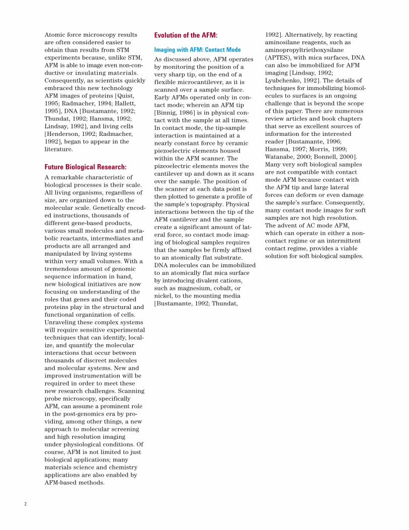
Fig. 1: High-resolution AFM image of S-layerproteins isolated from bacteria and imaged byMAC Mode in liquid.
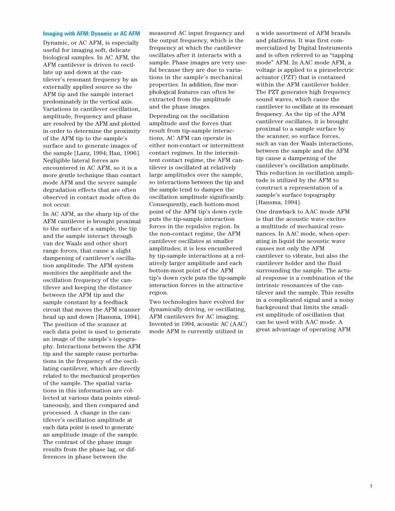
Fig. 2: MAC Mode AFM image of livingRhodopseudomonas palastris bacteria immo-bilized on a gelatin coated mica surface andimaged in liquid.
4
or cantilever scanning, because theAFM cantilever is mounted directlyon the AFM scanner, which istranslated onto the sample forimaging. This avoids many of theproblems associated with samplescanning and can offer significantadvantages for combining AFM withother instruments or accessories.For example, the AFM can be com-bined with an optical microscope.Alternative sample stage configu-rations, such as heating-coolingdevices or additional translatablestages for positioning microarrays,can also be implemented in theopen space underneath the samplestage in a top-down scanning AFM.However, most commercial AFMsutilize a cantilever tracking mecha-nism that is based on laser beamdeflection to maintain the laser’sposition on the cantilever duringimaging. Laser tracking systemsare often complex and requiregreat precision in assembly. Animperfection in the beam trackingmechanism can cause issues withthe position of the cantilever,resulting in defects in the images.
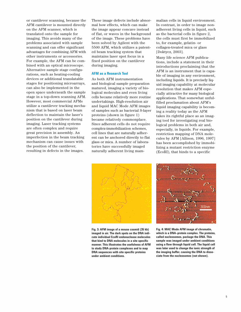
Fig. 3: AFM image of a mouse cosmid (35 kb)imaged in air. The dark spots on the DNA indi-cate individual EcoRI endonuclease moleculesthat bind to DNA molecules in a site specificmanner. This illustrates the usefulness of AFMto study DNA-protein complexes and to mapDNA sequences with site specific proteinsunder ambient conditions.
Fig. 4: MAC Mode AFM image of chromatin,which is a DNA–protein complex. The proteins,called nucleosomes, package the DNA. Thissample was imaged under ambient conditionsusing a flow through liquid cell. The liquid cellwas later used to change the ionic strength ofthe imaging buffer, causing the DNA to disso-ciate from the nucleosomes (not shown).
These image defects include abnor-mal bow effects, which can makethe image appear concave insteadof flat, or waves in the backgroundof the image. These problems havebeen solved by Agilent with the5500 AFM, which utilizes a patent-ed beam tracking system thatmaintains laser spot focus in afixed position on the cantileverduring imaging.
AFM as a Research Tool
As both AFM instrumentation and biological sample preparationmatured, imaging a variety of bio-logical molecules and even livingcells became relatively more routineundertakings. High-resolution airand liquid MAC Mode AFM imagesof samples such as bacterial S-layerproteins (shown in figure 1)became relatively commonplace.Since adherent cells do not requirecomplex-immobilization schemes,cell lines that are naturally adher-ent can be anchored directly to flatglass or mica. A number of labora-tories have successfully imagednaturally adherent living mam-
malian cells in liquid environment.In contrast, in order to image non-adherent living cells in liquid, suchas the bacterial cells in figure 2,the cells must first be immobilizedto, for example, gelatin- or collagen-treated mica or glass [Doktycz, 2003].
Many life science AFM publica-tions, include a statement in theirintroductions proclaiming that theAFM is an instrument that is capa-ble of imaging in any environment,including liquids. It is precisely liq-uid imaging capability at molecularresolution that makes AFM espe-cially attractive for many biologicalapplications. That somewhat unful-filled proclamation about AFM’sliquid imaging capability is becom-ing a reality today as the AFMtakes its rightful place as an imag-ing tool for investigating real bio-logical problems in both air and,especially, in liquids. For example,restriction mapping of DNA mole-cules by AFM [Allison, 1996, 1997]has been accomplished by immobi-lizing a mutant restriction enzyme(EcoRI), that binds to a specific
5
1
Forc
e (n
N)
Extension (nm)
0.8
1.6
1.4
1.2
0.0
-0.20 50 100 150 200 250 300
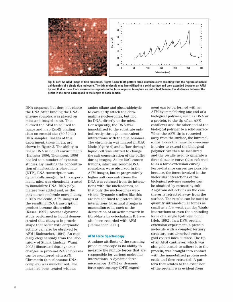
Fig. 5: Left: An AFM image of titin molecules. Right: A saw tooth pattern force-distance curve resulting from the rupture of individ-ual domains of a single titin molecule. The titin molecule was immobilized to a solid surface and then extended between an AFMtip and that surface. Each maxima corresponds to the force required to rupture an individual domain. The distances between thepeaks in the curve correspond to the length of each domain.
DNA sequence but does not cleavethe DNA.After binding the DNA-enzyme complex was placed onmica and imaged in air. Thisallowed the AFM to be used toimage and map EcoRI bindingsites on cosmid size (30-50 kb)DNA samples. Images of thisexperiment, taken in air, areshown in figure 3. The ability toimage DNA in liquid environments[Hansma 1996; Thompson, 1996]has led to a number of dynamicstudies. By limiting the concentra-tion of nucleotide triphosphate(NTP), RNA transcription wasdynamically imaged. In this experi-ment, mica was chemically treatedto immobilize DNA. RNA poly-merase was added and, as thepolymerase molecule moved alonga DNA molecule, AFM images ofthe resulting RNA transcriptionproduct became discernible[Kasas, 1997]. Another dynamicstudy performed in liquid demon-strated that changes in proteinshape that occur with enzymaticactivity can also be observed byAFM [Radmacher, 1994]. An espe-cially elegant study from the labo-ratory of Stuart Lindsay [Wang,2003] illustrated that dynamicchanges in protein-DNA complexescan be monitored with AFM.Chromatin (a nucleosome-DNAcomplex) was immobilized. Themica had been treated with an
amino silane and glutaraldehydeto covalently attach the chro-matin’s nucleosomes, but not its DNA, directly to the mica.Consequently, the DNA was immobilized to the substrate only indirectly, through noncovalent interactions with the nucleosomes.The chromatin was imaged in MACMode (figure 4) and a flow-throughliquid cell was utilized to changethe salt concentration of the bufferduring imaging. At low NaCl concen-trations, intact nucleosome-DNAcomplexes were observed in theAFM images, but at progressivelyhigher salt concentrations theDNA was released from its interac-tions with the nucleosomes, sothat only the nucleosomes werevisible. Dynamic studies like thisare not confined to protein-DNAinteractions. Structural changes inmammalian cells, such as thedestruction of an actin network infibroblasts by cytochalasin B, havealso been recorded with AFM[Radmacher, 2000].
AFM Force Spectroscopy
A unique attribute of the scanningprobe microscope is its ability tomeasure the minute forces that areresponsible for various molecularinteractions. A dynamic forcemicroscopy (DFM) or dynamicforce spectroscopy (DFS) experi-
ment can be performed with anAFM by immobilizing one end of abiological polymer, such as DNA ora protein, to the tip of an AFMcantilever and the other end of thebiological polymer to a solid surface.When the AFM tip is retractedaway from the surface, the intramol-ecular forces that must be overcomein order to extend the biologicalpolymer can then be measuredand the results used to generate aforce-distance curve (also referredto as a force-extension curve).Force-distance curves are possiblebecause, the forces involved in themolecular interactions of the biological polymer samples can be obtained by measuring sub-Angstrom deflections as the can-tilever is retracted away from thesurface. The results can be used toquantify intramolecular forces assmall as a few weak van der Waalsinteractions or even the unbindingforce of a single hydrogen bond[Hoh, 1992]. In a DFM proteinextension experiment, a proteinmolecule with a complex tertiarystructure was absorbed onto agold coated mica surface. The tipof an AFM cantilever, which wasalso gold coated to adhere it to theprotein, was brought into contactwith the immobilized protein mol-ecule and then retracted. A pat-tern that relates to the extensionof the protein was evident from
6
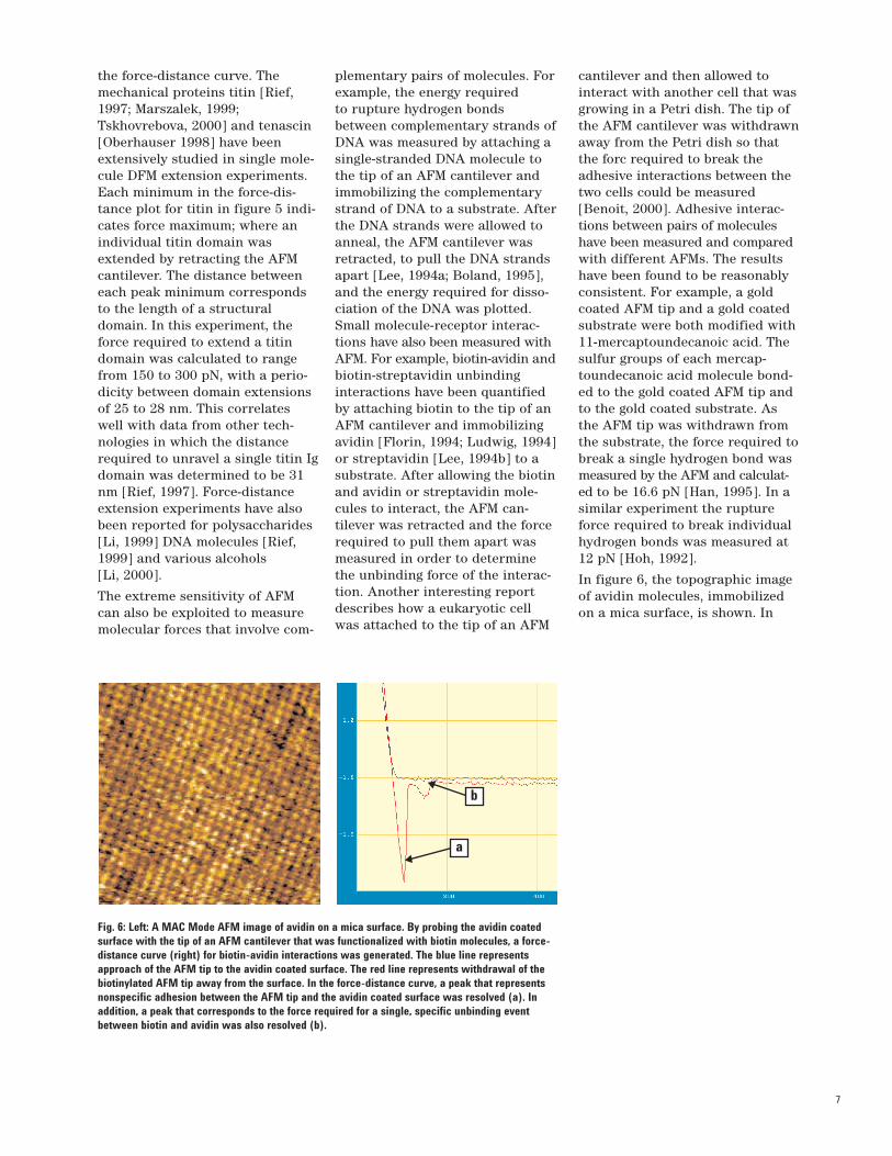
Fig. 6: Left: A MAC Mode AFM image of avidin on a mica surface. By probing the avidin coatedsurface with the tip of an AFM cantilever that was functionalized with biotin molecules, a force-distance curve (right) for biotin-avidin interactions was generated. The blue line representsapproach of the AFM tip to the avidin coated surface. The red line represents withdrawal of thebiotinylated AFM tip away from the surface. In the force-distance curve, a peak that representsnonspecific adhesion between the AFM tip and the avidin coated surface was resolved (a). Inaddition, a peak that corresponds to the force required for a single, specific unbinding eventbetween biotin and avidin was also resolved (b).
b
a
the force-distance curve. Themechanical proteins titin [Rief,1997; Marszalek, 1999;Tskhovrebova, 2000] and tenascin[Oberhauser 1998] have beenextensively studied in single mole-cule DFM extension experiments.Each minimum in the force-dis-tance plot for titin in figure 5 indi-cates force maximum; where anindividual titin domain wasextended by retracting the AFMcantilever. The distance betweeneach peak minimum correspondsto the length of a structuraldomain. In this experiment, theforce required to extend a titindomain was calculated to rangefrom 150 to 300 pN, with a perio-dicity between domain extensionsof 25 to 28 nm. This correlateswell with data from other tech-nologies in which the distancerequired to unravel a single titin Igdomain was determined to be 31nm [Rief, 1997]. Force-distanceextension experiments have alsobeen reported for polysaccharides[Li, 1999] DNA molecules [Rief,1999] and various alcohols [Li, 2000].
The extreme sensitivity of AFMcan also be exploited to measuremolecular forces that involve com-
cantilever and then allowed tointeract with another cell that wasgrowing in a Petri dish. The tip ofthe AFM cantilever was withdrawnaway from the Petri dish so thatthe forc required to break theadhesive interactions between thetwo cells could be measured[Benoit, 2000]. Adhesive interac-tions between pairs of moleculeshave been measured and comparedwith different AFMs. The resultshave been found to be reasonablyconsistent. For example, a goldcoated AFM tip and a gold coatedsubstrate were both modified with11-mercaptoundecanoic acid. Thesulfur groups of each mercap-toundecanoic acid molecule bond-ed to the gold coated AFM tip andto the gold coated substrate. Asthe AFM tip was withdrawn fromthe substrate, the force required tobreak a single hydrogen bond wasmeasured by the AFM and calculat-ed to be 16.6 pN [Han, 1995]. In asimilar experiment the ruptureforce required to break individualhydrogen bonds was measured at12 pN [Hoh, 1992].
In figure 6, the topographic imageof avidin molecules, immobilizedon a mica surface, is shown. In
plementary pairs of molecules. Forexample, the energy required to rupture hydrogen bondsbetween complementary strands ofDNA was measured by attaching asingle-stranded DNA molecule tothe tip of an AFM cantilever andimmobilizing the complementarystrand of DNA to a substrate. Afterthe DNA strands were allowed toanneal, the AFM cantilever wasretracted, to pull the DNA strandsapart [Lee, 1994a; Boland, 1995],and the energy required for disso-ciation of the DNA was plotted.Small molecule-receptor interac-tions have also been measured withAFM. For example, biotin-avidin andbiotin-streptavidin unbindinginteractions have been quantifiedby attaching biotin to the tip of anAFM cantilever and immobilizingavidin [Florin, 1994; Ludwig, 1994]or streptavidin [Lee, 1994b] to asubstrate. After allowing the biotinand avidin or streptavidin mole-cules to interact, the AFM can-tilever was retracted and the forcerequired to pull them apart wasmeasured in order to determinethe unbinding force of the interac-tion. Another interesting reportdescribes how a eukaryotic cellwas attached to the tip of an AFM
7
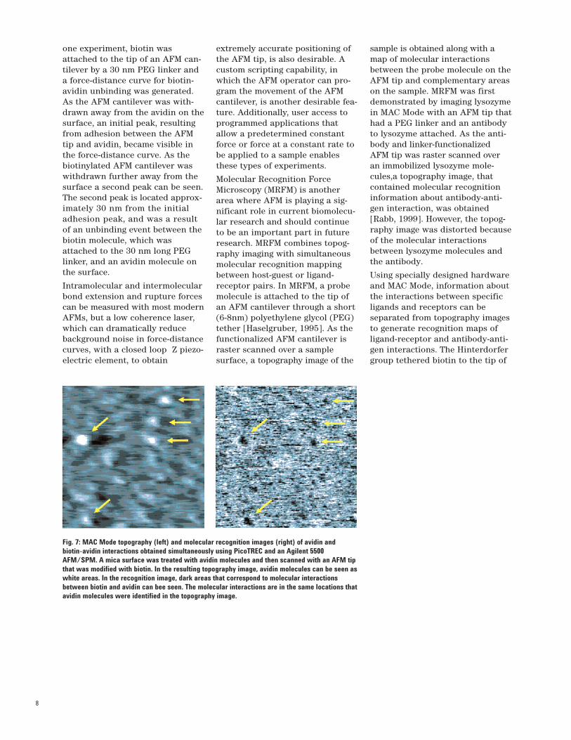
Fig. 7: MAC Mode topography (left) and molecular recognition images (right) of avidin andbiotin-avidin interactions obtained simultaneously using PicoTREC and an Agilent 5500AFM/SPM. A mica surface was treated with avidin molecules and then scanned with an AFM tipthat was modified with biotin. In the resulting topography image, avidin molecules can be seen aswhite areas. In the recognition image, dark areas that correspond to molecular interactionsbetween biotin and avidin can bee seen. The molecular interactions are in the same locations thatavidin molecules were identified in the topography image.
one experiment, biotin wasattached to the tip of an AFM can-tilever by a 30 nm PEG linker anda force-distance curve for biotin-avidin unbinding was generated.As the AFM cantilever was with-drawn away from the avidin on thesurface, an initial peak, resultingfrom adhesion between the AFMtip and avidin, became visible inthe force-distance curve. As thebiotinylated AFM cantilever waswithdrawn further away from thesurface a second peak can be seen.The second peak is located approx-imately 30 nm from the initialadhesion peak, and was a resultof an unbinding event between thebiotin molecule, which wasattached to the 30 nm long PEGlinker, and an avidin molecule onthe surface.
Intramolecular and intermolecularbond extension and rupture forcescan be measured with most modernAFMs, but a low coherence laser,which can dramatically reducebackground noise in force-distancecurves, with a closed loop Z piezo-electric element, to obtain
extremely accurate positioning ofthe AFM tip, is also desirable. Acustom scripting capability, inwhich the AFM operator can pro-gram the movement of the AFMcantilever, is another desirable fea-ture. Additionally, user access toprogrammed applications thatallow a predetermined constantforce or force at a constant rate tobe applied to a sample enablesthese types of experiments.
Molecular Recognition ForceMicroscopy (MRFM) is anotherarea where AFM is playing a sig-nificant role in current biomolecu-lar research and should continueto be an important part in futureresearch. MRFM combines topog-raphy imaging with simultaneousmolecular recognition mappingbetween host-guest or ligand-receptor pairs. In MRFM, a probemolecule is attached to the tip ofan AFM cantilever through a short(6-8nm) polyethylene glycol (PEG)tether [Haselgruber, 1995]. As thefunctionalized AFM cantilever israster scanned over a sample surface, a topography image of the
sample is obtained along with amap of molecular interactionsbetween the probe molecule on theAFM tip and complementary areason the sample. MRFM was firstdemonstrated by imaging lysozymein MAC Mode with an AFM tip thathad a PEG linker and an antibodyto lysozyme attached. As the anti-body and linker-functionalizedAFM tip was raster scanned overan immobilized lysozyme mole-cules,a topography image, thatcontained molecular recognitioninformation about antibody-anti-gen interaction, was obtained[Rabb, 1999]. However, the topog-raphy image was distorted becauseof the molecular interactionsbetween lysozyme molecules andthe antibody.
Using specially designed hardwareand MAC Mode, information aboutthe interactions between specificligands and receptors can be separated from topography imagesto generate recognition maps ofligand-receptor and antibody-anti-gen interactions. The Hinterdorfergroup tethered biotin to the tip of
8
an AFM cantilever and immobi-lized avidin on a mica substrate.As the biotinylated AFM tip wasscanned over the avidin coatedsubstrate, MAC Mode topographyimages for avidin and recognitionimages for the biotin-avidin inter-action were resolved and plottedsimultaneously (figure 7). Thehardware that is required toresolve molecular recognitionimages from MAC Mode topogra-phy images, called PicoTREC, isavailable as an option to Agilent’s5500 series AFM/SPM.
Microarray analysis by AFM
Microarray technology has madeits biggest impact in the areas ofgene expression profiling and DNAsequence or SNP identification,but other materials besides nucleicacids, including proteins, mem-branes, cells, and small molecules,can also be arrayed and assayedfor activity with microarrays.Unfortunately, convenient labelingand detection methods for materi-als other than nucleic acids andproteins are not readily available.However, development of so calledlabel-less detection schemes wouldbe of benefit to microarray tech-nology. Conventional microarraysare routinely created by variousmeans, including, reagent jetting, pin-based spotting, or lithographic techniques.Microarrays are typically com-posed of individual micron-sizedspots of discrete chemical identityorganized on glass microscopeslides. Hundreds or thousands ofthese spots can be arranged on a
typical microarray. The arrays canbe reacted with various assayreagents and, with the aid of spe-cialized instrumentation and software, thousands of specificinteractions evaluated. Currentmicroarray technology calls atten-tion to thousands of molecularinteractions on each array; it typi-cally does not quanify the forces ofinteraction between interactingspecies, nor does it evaluate theseinteractions at the single moleculelevel. By combining AFM withmicroarray technology, the forcesof molecular interaction betweenarray elements and here assayreagents can be determined.Various biological molecules canbe attached to AFM cantilevers,but dynamic force microscopyDFM on large arrays of biologicalmolecules will require advances inhardware and software. Thisrequires an AFM scanning mecha-nism in a top-down configurationand also that the AFM cantileverbe affixed to the scanning mecha-nism in order to permit a largeenough space under the sampleplate to accommodate a translat-able stage for aligning individualmicroarray elements with the AFMcantilever.
9
References:Allison, D. P., Kerper, P. S., Doktycz, M. J.,Spain, J. A., Modrich, P., Larimer, F. W.,Thundat, T., Warmack, R.J., “DirectAtomic-Force Microscope Imaging ofEcoRI Endonuclease”, Proc. Natl. Acad.Sci., 93(17), 8826 (1996).
Allison, D. P. Kerper, P. S., Doktycz, M. J.,Thundat, T., Modrich, P., Larimer, F. W.,Johnson, D. K., Hoyt, P. R., Mucenski, M.L., Warmack, R.J., “Mapping IndividualCosmid DNAs by Direct AFM Imaging”,Genomics, 41, 379 (1997).
Benoit, M., Gabriel, D., Gerisch, G., Gaub,H. E., ‘Discrete Interactions in CellAdhesion Measured by Single-moleculeForce Spectroscopy,” Nat. Cell Biol. 2,3134 (2000).
Binnig, G., Rohrer, H., “ScanningTunneling Microscopy”, Helva PhysicaAcata, 55(6), 726 (1982).
Binnig, G., Quate, C. F., Gerber, Ch.,“Atomic Force Microscopy,” Phys. Rev.Lett., 56, 930 (1986).
Boland, T., Ratner, B.D., “DirectMeasurement of Hydrogen Bonding inDNA Nucleotide Bases by Atomic ForceMicroscopy”, Proc. Natl. Acad. Sci., 92,5297 (1995)
Bonnell, D., “Scanning Probe Microscopyand Spectroscopy: Theory, Techniques,and Applications”, 2nd Edition, JohnWiley & Sons Inc. New York, (2000).
Bustamante, C., Vesenka, J., Tang, C. L.,Rees, W., Guthold, M., Keller, R., “CircularDNA Molecules Imaged in Air byScanning Force Microscopy,” Biochem, 31,22 (1992).
Bustamante, C., Rivetti, C., “VisualizingProtein-nucleic Acid Interactions on aLarge Scale with the Scanning ForceMicroscope,” Annu. Rev. Bioph. Biom.,25, 395 (1996).
Doktycz, M. J., Sullivan, C. J., Hoyt, P. R.,Pelletier, D. A., Wu, S. Allison, D. P. “AFMimaging of bacteria in liquid mediaimmobilized on gelatin coated mica sur-faces” Ultramicroscopy, 97(1-4), in press(2003).
Florin, E. L., Moy, V. T., Gaub, H. E.,“Adhesion Forces Between IndividualLigand-Receptor Pairs”, Science, 264, 415(1994)
Hallett, P., Offer, G., Miles, M. J., “AtomicForce Microscopy of the MyosinMolecule,” Biophys. J., 68, 1604 (1995).
Haselgrubler, T., Amerstorfer, A.,Schindler, H., Gruber, H., “Synthesis andApplications of a New Poly(ethyleneGlycol) Derivative for the Cross-Linkingof Amines with Thiols”, BioconjugateChemistry, 6, 242 (1995)
Han, T., Williams, J. M., Beebe, T. P.,“Chemical-bonds Studied withFunctionalized Atomic Force
Microscopy,” Anal. Chim. Acta., 307, 365(1995)
Han, W., Lindsay, S. M., Jing, T., “AMagnetically Driven Oscillating ProbeMicroscope for Operation in Liquids,”Appl. Phys. Lett., 69, 4111 (1996).
Hansma, H. G., Vesenka, J., Siegerist, C.,Kelderman, G., Morrett, H., Sinsheimer,R. L., Elings, V., Bustamante, C., Hansma,P. K., Reproducible Imaging andDissection of Plasmid DNA Under Liquidwith Atomic Force Microscope,” Science,256, 1180 (1992).
Hansma, H. G., Laney, D. E., “ DNABinding to Mica Correlates with CationicRadius: Assay by Atomic ForceMicroscopy,” Biophys. J., 70, 1933 (1996).
Hansma, H. G., Kim, K. J., Laney, D. E.,Garcia, R. A., Argaman, M., Allen, M. J.,Parsons, S. M., “Properties ofBiomolecules Measured From AtomicForce Microscope Images: A Review,” J.Struct. Biol., 119 (2), 99 (1997).
Hansma, P. K., Cleveland, J. P.,Radmacher, M., “Tapping Mode AtomicForce Microscopy in Liquids,” Appl. Phys.Lett., 64, 1738 (1994).
Henderson, E., Haydon, P. G., Sakaguchi,D. S., “Actin Filament Dynamics inLiving Glial Cells Imaged by AtomicForce Microscopy,” Science, 257, 1944(1992).
Hochachka, P. W., “The metabolic implica-tions of intracellular circulation,” Proc.Natl. Acad. Sci., 96 (22) 12233 (1999).
Hoh, J. H., Cleveland, J. P., Prater, C. B.,Revel, J-P., Hansma, P. K., “QuantizedAdhesion Detected with the Atomic ForceMicroscope”, J. Am. Chem. Soc., 114,4917 (1992)
Kasas, S., Thompson, N. H., Smith B. L.,Hansma, H. G., Zhu, X., Guthold, M.,Bustamante, C., Kool, E. T., Kashlev, M.,Hansma, P. K., “Escherichia coli RNAPolymerase Activity Observed UsingAtomic Force Microscopy, Biochemistry,36, 461 (1997)
Lantz, M., O’Shea, S. J., Welland, M. E.,“Force Microscopy Imaging in LiquidsUsing ac Techniques,” Appl. Phys. Lett.,65, 409 (1994).
Lee, G., Arscott, P. G., Bloomfield, V. A.,Evans, D. F., Scanning TunnelingMicroscopy of Nucleic Acids,” Science,244, 475 (1989).
Lee, G. U., Chrisey, L. A., Colton, R. J.,“Direct Measurement of the ForcesBetween Complementary Strands ofDNA”, Science, 266, 771 (1994a).
Lee, G. U., Kidwell, D. A., Colton, R. J.,“Sensing Discrete Streptavidin BiotinInteractions with Atomic ForceMicroscopy,” Langmuir, 10, 354 (1994b).
Li, H. B., Rief, M., Osterhelt,F., Gaub, H.E., Zhang, X., Shen, J. C., “Single
Summary:Scanning probe microscopy has maturedto a point where it can assume animportant role in life science researchin the twenty first century. The field is in a state of rapid growth.Manufacturers of commercial instru-ments are eager to incorporate promising new ideas from researchersinto commercial products. Since speculation about future developmentof instrumentation is risky, a betterapproach may be to look at the futureof biological research for directionsregarding the development of instru-mentation. The end of the twentiethcentury saw the sequencing of thehuman genome. Early in this century,a significant amount of effort in bio-logical research is being devoted tounderstanding how the products ofgenes interact to maintain physiologicalprocess, cells and living organisms. Ithas been indicated in this article thiswill require methods for identifying,mapping, and measuring a variety ofthe numerous, weak, single moleculeinteractions that occur within livingcells. How AFM development will beused to respond to these challengeshas yet to be determined.
10
Molecule Force Spectroscopy onPolysaccharides by AFMNanomechanical Fingerprint of ·-(1-4)-Linked Polysacharides,” Chem. Phys.Lett., 305, 197 (1999).
Li, H. B., Zhang, W., Xu, W., Zhang, H.,“Hydrogen Bonding Governs the ElasticProperties of Poly(vinyl alcohol) inWater: Single-molecule ForceSpectroscopic Studies of PVA by AFM,”Macromolecules, 33, 465 (2000).
Lindsay, S. M., Lyubchenko, Y. L., Gall, A.A., Shlyakhtenko, L. S., Harrington, R.E., “Imaging DNA Molecules ChemicallyBound to Mica Surfaces,” SPIEProceedings 1639, 84 (1992).
Ludwig, M., Moy, V. T., Rief, M., Florin, E.L., Gaub, H. E., “Characterization of theAdhesion Force Between Avidin-Functionalized Afm Tips andBiotinylated Agarose Beads”, MicroscopyMicroanalysis Microstructures, 5, 321(1994).
Lutwyche, M. I., Despont, M., Drechsler,U., Durig, U., Haberle, W., Rothuizen, H.,Stutz, R., Widmer, R., Binnig, G., Vettiger,P., “Highly Parallel Data Storage SystemBased on Scanning Probe Arrays”, Appl.Phys. Lett., 77 (20), 3299 (2000)
Lyubchenko, Y. L., Gall, A. A.,Shlyakhtenko, L. S., Harrington, R. E.,Oden, P. I., Jacobs, B. L., Lindsay, S. M.,“Atomic Force Microscopy Imaging ofDouble Stranded DNA and RNA,” J.Biomolecular Structural Dynamics, 9,589 (1992)
Marszalek, P. E., Lu, H., Li, H. B.,Carrion-Vazquez, M., Oberhauser, A. F.,Schulten, K., Fernandez, J. M.,“Mechanical Unfolding intermediates inTitin Molecules,” Nature, 402, 100(1999).
Morris, V. J., Kirby, A. R., Gunning, A. P.,“Atomic Force Microscopy forBiologists”, Imperial College Press,(1999).
Niemeyer, C. M., “Nanoparticles,Proteins, and Nucleic Acids:Biotechnology Meets Materials Science,”Agnew. Chem. Int. Ed., 40, 4128 (2001).
Oberhauser, A. F., Marszalek, P. E.,Erickson, H. P., Fernandez, J. M., “TheMolecular Elasticity of the ExtracellularMatrix Protein Tenascin,” Nature 393,181(1998).
Quist, A. P., Bjorck, L. P., Reimann, C. T.,Oscarsson, S. O., Sundquist, B. U. R., “AScanning Force Microscopy Study ofHuman Serum Albumin and PorcinePancreas Trypsin Adsorption on MicaSurfaces,” Surface Sci., 325, 406 (1995).
Raab, A., Han, W., Badt, D., Smith-Gill, S.J., Lindsay, S. M., Schindler, H.,Hinterdorfer, P., “Antibody RecognitionImaging by Force Microscopy”, Nat.Biotechnol., 17, 902 (1999)
Radmacher, M., Tillmann, R. W., Fritz, M.,Gaub, H. E., “From Molecules to Cells:Imaging Soft Samples with Atomic ForceMicroscope,” Science 257, 1900 (1992).
Radmacher, M., Fritz, M., Cleveland, J. P.,Walters, D. R., Hansma, P. K., “ImagingAdhesion Forces and Elasticity ofLysozume Adsorbed on Mica with theAtomic Force Microscope,” Langmuir, 10,3809 (1994).
Rief, M., Gautel, M., Oesterhelt, F.,Fernandez, J. M., Gaub, H. E., "ReversibleUnfolding of Individual TitinImmunoglobulin Domains by AFM”,Science, 276, 1109 (1997).
Rief, M., Clausen-Schaumann, H., Gaub, H.E., “Sequence-dependent Mechanics ofSingle DNA Molecules,” Nat. Struct. Biol.,6, 346 (1999).
Rotsch, C., Radmacher, M., “Drug-inducedChanges of Cytoskeletal Structure andMechanics in Fibroblasts: An AtomicForce Microscopy Study,” Biophys. J.78(1), 520 (2000).
Sonnenfeld, R., Hansma, P. K. “Atomic-res-olution Microscopy in Water,” Science,232, 211 (1986).
Thompson, N. H., Kasas, S., Smith, B.,Hansma, H. G., Hansma, P. K., “ReversibleBinding of DNA to Mica for AFM Imaging,”Langmuir, 12, 5905 (1996).
Thundat, T. Allison, D. P., Warmack, R. J.,Ferrell, T. L., “Imaging Isolated Strands ofDNA Molecules by Atomic ForceMicroscopy,” Ultramicroscopy, 42-44, 1101(1992).
Thundat, T., Allison, D. P., Warmack, R. J.,Brown, G. M., Jacobson, K. B., Schrick, J.J., Ferrell, T. L., “Atomic Force Microscopyof DNA on Mica and Chemically ModifiedMica,” Scanning Microsc. 6, 911 (1992).
Tskhovrebova, L., Han, W., Trinick, J.,“Studies of Mechanical Unfolding of SingleTitin Molecules Using AFM AC Mode,”Biophys. J., 78, 2627 (2000).
Wang, H. D., Bash, R., Yodh, J. G., Hager,G. L., Lohr, C., Lindsay, S. M.,“Glutaraldehyde Modified Mica: A NewSurface for Atomic Force Microscopy ofChromatin,” Biophys. J. 83 (6), 3619(2002).
Watanabe, Y., Sakurai, T., “Advances inScanning Probe Microscopy”, Springer-Verlag, New York, (2000).
Whitesides, G. M., and Grzybowski, B.,“Self-Assembly at All Scales,” Science 295,2418 (2002).
Xia, Y., Rogers, J. A., Paul, K. E. andWhitesides, G. M., “UnconventionalMethods for Fabricating and PatterningNanostructures,” Chem. Rev. 99(7), 1823(1999).
11

www.agilent.com/find/afm
For more information on Agilent Technologies’products, applications or services, pleasecontact your local Agilent office. The complete list is available at:
www.agilent.com/find/contactus
Phone or Fax
United States:(tel) 800 829 4444 (fax) 800 829 4433
Canada:(tel) 877 894 4414 (fax) 800 746 4866
China:(tel) 800 810 0189 (fax) 800 820 2816
Europe:(tel) 31 20 547 2111
Japan:(tel) (81) 426 56 7832 (fax) (81) 426 56 7840
Korea:(tel) (080) 769 0800 (fax) (080) 769 0900
Latin America:(tel) (305) 269 7500
Taiwan:(tel) 0800 047 86 (fax) 0800 286 331
Other Asia Pacific Countries:(tel) (65) 6375 8100 (fax) (65) 6755 0042Email: [email protected]: 09/14/06
Product specifications and descriptionsin this document subject to changewithout notice.
© Agilent Technologies, Inc. 2007Printed in USA, November 1, 20075989-6983ENRev. A1
AFM Instrumentation from Agilent Technologies
Agilent Technologies offers high-pre-cision, modular AFM solutions forresearch, industry, and education.Exceptional worldwide support isprovided by experienced applicationscientists and technical servicepersonnel. Agilent’s leading-edgeR&D laboratories ensure thecontinued, timely introductionand optimization of innovative,easy-to-use AFM technologies.
www.agilent.com