The Elements of Tailless Airplane Designa.moirier.free.fr/Conception/Formules%20sp%e9ciales/A… ·...
6
THE ELEMENTS OF TAILLESS AIRPLANE DESIGN By A. A. Backstrom (EAA 1162) Rt.l Frisco, TX 75034 J. HERE HAS BEEN over the years a tendency to classify tailless airplane design as an area of mystique practiced by persons very adept in the manipulation of Ouija boards. The people using these guidelines seem to be able to overlook the well-engineered airplanes that have shown good flight characteristics. Several of these have been certificated by the country of origin or used operationally by their military units. After we have dis- cussed the design problems, I will present some informa- tion on designs worthy of further development. The first decision in tailless airplane design is: WHY? To answer that question let's tabulate the pri- mary advantages and disadvantages. Goodies 1. Reduced drag 2. Reduced weight 3. Simpler structure (possible) Discussion The advantage of tailless airplanes is that for an equivalent payload, a lighter airplane requiring less power and fuel can be designed. MAC The CG range can be greatly extended by using low aspect ratio as in the Delta or Hoffman types. These are not normally suited to small airplanes because of the high power requirements at climb speed. Baddies 1. Reduced CG range 2. Limited use of high lift devices Discussion The small CG range will kill off mid-sized airplanes. To obtain a usable design the variable weights must be very small or the airplane large so the weights can be distributed spanwise near the CG. To be blunt about it, don't try to design a Cherokee Six equivalent. The lim- ited use of high lift devices makes achieving a large speed range difficult. Well, if the goodies outweigh the baddies to you, let's go on and look at small tailless airplane design consid- erations point-by-point. (I assume that if you want a very large tailless airplane you will get your own Ouija board.) Wing Configuration As in any other airplane, the wings may be straight, swept back, or swept forward with various combinations of taper and twist. Determine wing sweep at the .25 chord line. Figure 1 illustrates these layouts and the re- SWEPT BACK PLANK MAC FIGURE 1 STABLE WING SYSTEMS & THEIR LIFT DISTRIBUTIONS SPORT AVIATION 39
Transcript of The Elements of Tailless Airplane Designa.moirier.free.fr/Conception/Formules%20sp%e9ciales/A… ·...
THE ELEMENTS OF TAILLESSAIRPLANE DESIGN
By A. A. Backstrom (EAA 1162)Rt.l
Frisco, TX 75034
J. HERE HAS BEEN over the years a tendency toclassify tailless airplane design as an area of mystiquepracticed by persons very adept in the manipulation ofOuija boards. The people using these guidelines seem tobe able to overlook the well-engineered airplanes thathave shown good flight characteristics. Several of thesehave been certificated by the country of origin or usedoperationally by their military units. After we have dis-cussed the design problems, I will present some informa-tion on designs worthy of further development.
The first decision in tailless airplane design is:WHY? To answer that question let's tabulate the pri-mary advantages and disadvantages.
Goodies1. Reduced drag2. Reduced weight3. Simpler structure (possible)
DiscussionThe advantage of tailless airplanes is that for an
equivalent payload, a lighter airplane requiring lesspower and fuel can be designed.
MAC
The CG range can be greatly extended by using lowaspect ratio as in the Delta or Hoffman types. These arenot normally suited to small airplanes because of thehigh power requirements at climb speed.
Baddies1. Reduced CG range2. Limited use of high lift devices
DiscussionThe small CG range will kill off mid-sized airplanes.
To obtain a usable design the variable weights must bevery small or the airplane large so the weights can bedistributed spanwise near the CG. To be blunt about it,don't try to design a Cherokee Six equivalent. The lim-ited use of high lift devices makes achieving a largespeed range difficult.
Well, if the goodies outweigh the baddies to you, let'sgo on and look at small tailless airplane design consid-erations point-by-point. (I assume that if you want avery large tailless airplane you will get your own Ouijaboard.)
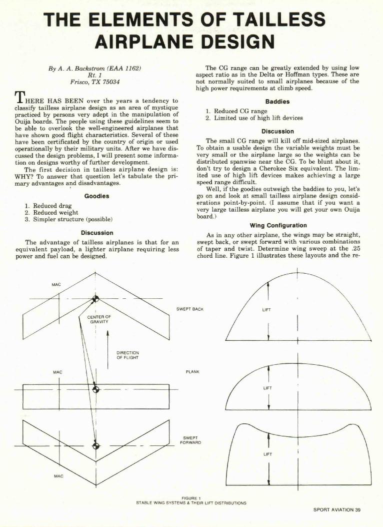
Wing ConfigurationAs in any other airplane, the wings may be straight,
swept back, or swept forward with various combinationsof taper and twist. Determine wing sweep at the .25chord line. Figure 1 illustrates these layouts and the re-
SWEPT BACK
PLANK
MAC
FIGURE 1STABLE WING SYSTEMS & THEIR LIFT DISTRIBUTIONS
SPORT AVIATION 39

quired wing lift distributions. Of special interest is theswept forward configuration. I do not recommend tryingthe swept forward layout due to the highly loaded tipsand the fact that they must either stall first or be pre-vented from ever stalling. Of course, for satisfactoryflight characteristics the tips cannot be allowed to stallfirst. Some NACA Wartime Reports show the proposedCornelius glider tanker to be about the worst of the tail-less designs tested. A small amount of sweep forward toproduce a straight leading edge, as used by Jim Marske,can produce good results.
So this leaves us with straight and swept back. Thedetermination of which to use will depend on the CGtravel required. Put simply, the more CG travel thatmust be tolerated, the more sweep required. Figure 2shows an in-work auxiliary powered plank sailplane de-sign intended for almost zero CG travel regardless ofweight changes. You may ask why work for small CGtravel if it could be controlled by incorporating sweep.Well, the opposite problem is that the smaller the sweepangle the better the performance should be.
will depend on whether the airfoil (or wing system forswept types) has a nose up (+) or nose down (-) pitch-ing moment coefficient. Also, the stability is directlytied to the CG location. Figure 6 shows the stabilitybuild up of the components of a conventional airplaneand the effect of CG location. I hope you can reviewthese figures and see that once you establish an airplaneconfiguration, the location of the CG relative to theneutral point determines the static longitudinal stabil-ity.
Harry's numbers in Figure 6 are approximate, butthey will serve to illustrate that a tailless design willhave the neutral point well forward of a tailed type. Ona wing alone the neutral point is approximately 25%mean aerodynamic chord (MAC). The addition of a podas required for small machines will shift this slightly.
There is one other factor to be considered in designand that is protection of the rear CG limit. The taillessairplane should be designed so that in normal loading itwill be very difficult to load the airplane aft of the es-tablished rear CG limit. This is because the range be-
FUEL 3 GALS. MAX P|LOT WT AFT CGCOULD BE IN LIGHTER PILOTS WILL BEWING AT CG FORWARD OF THIS POINT
THRUST LINE
FIGURE 2PLANK CONFIGURATION DESIGNED FOR
MINIMUM CG TRAVEL
Longitudinal Stability and CG LocationUnderstanding longitudinal stability in airplanes
provokes one of my pet peeves. I have heard the follow-ing statement thousands of times: "I know why a con-ventional airplane is stable, but I don't understand whyyours is." Now really, if you understand one, you under-stand the other. To help all these people understandwhy airplanes are or are not longitudinally stable, let'stake a quickie course on the subject using figures fromHarry Hurt's excellent book, Aerodynamics For NavalAviators. In these figures, Cm is pitching moment coef-ficient of the entire airplane, Cmac is pitching momentcoefficient of the wing about the aerodynamic center,appproximately 25% chord at subsonic speeds. The signconvention is + for nose (or leading edge) up. Cl is liftcoefficient, and increased Cl at fixed weight meanslower speed or higher load factor.
Figure 3A shows characteristics of a Cm vs Cl curvefor a typical stable airplane. Stick fixed it will trim atthe point marked Cm = 0 and when the airplane is dis-placed from this Cl it will tend to return to the Cm = 0point. Figure 3B shows the other possible stability con-ditions and that the stability is directly proportional tothe slope of the curve. Ordinarily the static longitudinalstability does not change with Cl except in the rangewhere Cl Vs angle of attack is no longer linear. Figure3C shows a possible condition with changes due to powereffect, high lift devices, wing location, etc.
Figures 4 and 5 show what a wing alone can contrib-ute to longitudinal stability. You will note that a wingalone can be stable or unstable and that the trim point
AIRPLANEREAR CGPOINT
LESS STABLE NEUTRAL
FIGURE 3AIRPLANE STATIC LONGITUDINAL STABILITY
40 MAY 1979

CHANGE IN LIFT
-AERODYNAMIC CENTER
-CENJER OF GRAVITY
FIGURE 4WING CONTRIBUTION
STABLE. POSITIVE Cy
NEGATIVE CM .UNSTAI
"
STABU.NEGATIVE CMA£
FIGURE 5EFFECT OF CMAC. C.G. POSITION
tween unstable and unflyable is smaller than a tailedtype.
Well, now to the final point — where to put the CG(you thought I would never get there, didn't you!). Onmy flying planks we have used from 15 to 22 percentMAC. The range forward of about 18% results in largeelevon deflection and high trim drag. So for a new de-sign, use about 20% MAC to start with and work for-ward and back slowly to determine what the design canhandle. You can refer to most aerodynamics text booksfor ways to determine MAC.
This was more discussion than I intended, but I hopeit has helped you understand the basic principles of sta-tic longitudinal stability.
Directional StabilityMost of the reports of poor flight characteristics I
have heard of in tailless airplanes are the result of poordirectional stability. It seems that some designers, aim-ing at drag reduction, lose sight of the fact that it won'tfly right if it doesn't go in a straight line. The solution
TYPICAL BULD-U(> OF COMPONENTS
-WMG-f FUSELAGE
C.6 9 JO% MAC
EFFECT OF CG POSITION
50% MAC
FIGURE 6STABILITY BUILD-UP AND EFFECT OF C G POSITION
to the problem is simply to have enough vertical surfacefar enough aft to accomplish this. On a swept wing youmight use a diffuser tip as shown in Figure 7 ratherthan tip fins. You should note that both the bend downand the canting of the break line are required for a dif-fuser tip.
The roll your own section will provide you with in-formation on how to find out how much area, etc.
Aerodynamic ControlsIn selection of design for aerodynamic controls, you
should try and select types that will produce a minimumof adverse secondary effects. You may refer to the draw-ings of successful designs for some information on pro-portion.
I personally favor wing tip elevens for pitch and rollcontrol because they will build in additional wash out inthe tip area at low speed which will help prevent tipstalling and increase spin resistance. On straight wingdesigns with pusher engines tip fins and drag ruddersshould be used. With a straight wing tractor a single finon the aft pod can be used if it is far enough aft. Don'tcopy the EPB-lc in the EAA Museum because the armis too short; it was done that way to keep the sailplanetrailerable. If you have a similar design problem youshould use a fixed fin and drag rudders at the wing tip.The drag rudders may be like Jim Marske's XM-1D or aflap on the upper surface only with the lower surfacefixed (similar to that shown in Figure 7 or the plankmodification shown in Soaring, July 1972). On a sweptwing design the diffuser tip with a drag flap rudder (seeFigure 7) or a small vertical surface and outward mov-ing rudder can be used. Drag flaps of this type on dif-
SPORT AVIATION 41

fuser tips, in addition to providing the yaw forces, willproduce a roll force in the desired direction and somedesired up pitch force during a turn.
AFT VIEW- CHORD PLANE
ONLY SHOWN
DIRECTION OF FLIGHT
BREAK LINE. ANGLE RELATIVETO CL WILL DETERMINETIP WASHOUT
DRAG RUDDER,HINGES UP ON TOPSURFACE ONLY
FIGURE 7DIFUSER WING TIPS
NOSE GEAR POSITIONS^.TAKE OFF/LAND - TAXIAJP - PARK
MAIN GEARSTATIC
FIGURE 8
Power EffectsFor our small airplane discussion only propeller
types will be covered. As a tractor propeller will gener-ally reduce the stability of an airplane, it is desirable toarrange for a minimum of adverse forces to be coun-teracted. Ideally, you would want power changes to bemade with no control corrections being required. To ac-complish or approach this, it is necessary to use anoffset thrust line. Vertically the thrust line should beslightly above the CG and should be canted (left or rightdepending on propeller rotation) to counteract the com-bination of things generally referred to as torque. Theoffset thrust lines are illustrated in Figure 2. If possible,the thrust line should be adjustable in a prototype toallow a best setting to be found, just like a free flightmodel airplane.
For a pusher design, the problem is somewhat sim-pler since no left or right offset is necessary. The thrustline should pass slightly above the vertical CG location.You can see this shown in Figure 8.
The vertical location of the thrust line for a tractorshould not be more than 20% MAC above the CG andnot more than 10% for a pusher.
SpinsThere was at one time the belief that tailless
airplanes could not be made to spin. Sorry, but this isjust an old pilot's tale. In fact, during the thirties theHill Pterodactyls were spin tested and I remember Dr.
42 MAY 1979
Lippisch telling of the German authorities requiringhim to do extensive rework on one of his Delta series sothat he could show that it would spin and recover. Tail-less airplanes can, and should, be designed to be un-spinnable but it must be done in the basic design ratherthan hoping it will fall out naturally.
Basically, to prevent spins it is necessary to main-tain a large amount of damping in roll at minimum fly-ing speed. To accomplish this, most of the outer sectionof the wing must not be stalled. This can be obtained bywing twist, slots, elevens (which provide effective washout in the up range), or a combination of these. Also,tailless airplanes need to have the same stability poweron as power off. Offset thrust lines, as discussed in thesection on power effects, can provide this.
Landing GearMost tailless airplanes of today use a tricycle type
landing gear. If you design one around a tail wheel, youcan use the geometry Pazmany calls out in his book onlightplane design. Paz's information on tricycle gear isalso satisfactory except in many cases it will have toomuch load on the nose wheel. Due to the limitedelevator power on many tailless designs, they cannotraise the nose wheel early enough in the take off rollwithout help from wing lift. This requires that theairplane sit at a high deck angle which will reduce nosewheel load. The resultant will be poor nose wheel steer-ing authority if this is used for ground control. In somecases also the empty airplane will sit with the tail onthe ground which makes it easy to blow away. Figure 2shows an arrangement with a single position nose gearthat will have more weight on it empty than loaded. Fig-ure 8 shows a multi-position nose wheel arrangementinspired by Burt Rutan's VariEze. This allows a lightlyloaded nose wheel for take off, moderate load for landingand taxiing, and a negative ground angle for parking.
High Lift DevicesAlthough the use of high lift devices is limited, there
are some things that can be done to reduce minimumspeeds. Slots can be used full span to increase Cl maxbut the increased angle of attack required will lead tolanding gear design problems. This was the reason forthe extreme gear design on the Vought F7U-3 airplanes.Conventional trailing edge flaps can be used on someswept back designs. A split flap would be the preferredtype.
There have been several proposals to use a centrallymounted flap on swept wing tailless designs as anelevator. This is an intriguing idea as the elevatorwould be deflected downward and increase Cl at lowspeed. An elevon type control system reduces Cl at lowspeed. With proper aspect ratio and sweep angles it willwork in small models and Figure 9 shows such a plan-form layout.
FIGURE 9PLANFORM LAYOUT FOR
DESIGN INTENDED FOR INBOARDELEVATOR

.2 TO 25 WPB-1 Summer Of 75 Conlig.WING SPAN Span 2V8"
Chord 46"Wing Area 97 5 Sq. Ft.Length 1V1"
—— DRAG FLAPOPENS OUTONLY (70°)
APPROX 25 CHORD AFTOF HINGE LINE ELEVONAPPARENTLY BUILT LIKEFRIEZE AILERON
FIGURE tO
ELEVON DEFLECTIONUP 26° DOWN 10°
?I22XSPANl
WING AIRFOILNACA 23012TWIST 4° WASHOUT
25°
WATERMAN AEHOBILESPAN 38' — CHORD 7'WTS 1710 EMPTY
2500 GROSSPOWERED BY STUDEBAKEROR TUCKER AUTOMOTIVEENGINES WAS ALSOLICENSED FOR ROAD USEWITH WINGS REMOVED.
RUDDER DEFLECTION25° OUT IN 0
FIGURE 11
Designs For Further DevelopmentI started to call this section "Designs Worth Copy-
ing", but I thought better of it. For a long time I haveconsidered a good designer to be one who only copiesgood ideas. There are two people who have good designsthat are not covered here. This is because they are bothstill active and selling drawings. They are Jim Marske,130 Crestwood Drive, Michigan City, IN 46360 andCharles Fauvel, 72 Boulevard Cornot, 06400 CannesAM, France. Jim has a line of sailplane designs andFauvel has both sailplanes and small airplanes. Largelyforgotten these days is the fact that the Fauvel AV10was certificated in France in the thirties and at onetime held its class altitude record. (Also, a two-placeplank sailplane has been certificated in Australia.)
Figures 10, 11 and 12 show a Flying Plank, Water-man Aerobile, and the Messerschmitt Me. 163. Very gooddetailed drawings of Waterman's Aerobile are availablefrom Paul R. Matt, Box 33, Temple City, CA 91780. Ihave presented the Me. 163 because I do not have anydetailed information on Dr. Lippisch's Delta seriesairplanes. If anyone has detailed information on these Iwould l ike to get a copy or, better yet, they should writethem up for publication.
1 would not recommend copying the true flying wingtypes unless you are wil l ing to make revisions to in-crease directional stability.
Where To Find More InformationI have had many inquiries for material on tailless
airplane theory and practice, etc. so I will pass along mynormal reply. The best general study of tailless airplanehistory, stability, etc., was written by A. R. Weyl andpublished in Aircraft Engineering magazine during 1944and 1945. This is a British publication, but there arecopies in several engineering libraries in the U. S. Dur-ing World War II, NACA did a lot of tailless airplanestudies that are covered in Wartime Reports. These re-
ELEVONSLOT
ME 163 ROCKETINTERCEPTOR
FIGURE 12
ports cover one study each, but they are worth readingto find out what did or did not work in the wind tunnels.WR-L-199 was the report that convinced me to proceedwith the plank design.
Roll Your Own?The rest of this discussion is primarily intended for
those people interested in true experimental design de-velopment.
As in any design work, the first step is to set yourobjectives, performance parameters, etc. When this isdone you can start sketching out a design that you feelmight meet them. For now, we will only consider de-velopment of a stable and flyable airplane; performanceis a separate problem. From your sketches, develop ascale layout to see if you can fit everything into yourenvelope. Looks pretty, doesn't it? Will it work? Well,let's use an example to find out. Figure 13 shows asmall amphibian design I started a few years back. Notethe drawing description, "Concept Layout." The finishedmachine may be a lot different. So build a scale profileglider model (about 1/20 scale) as shown in Figure 14.You must be able to make this fly stably across theroom. Any changes required must be shown back onyour layout. You can experiment with drastic changeseasily at this stage so see what you can do to make itbetter.
The next step is to go three dimensional at about1/10 scale, glider or powered free flight. This will let youlook at your lines, etc. and further check stability.Again carry any changes necessary back to your layout.
Now, depending on your faith, guts or whatever, youcan go to a R/C model or full scale. A 1/5 or larger scaleR/C model can check many static stability and controleffectiveness items. For instance, we would have foundthat the WPB-1 layout would have a landing geargeometry problem if this step had been taken. If you goto dynamic scaling, a lot of additional items can bechecked, but for small airplanes it is almost as easy togo full scale.
SPORT AVIATION 43

EpilogueThe tailless airplane offers the most potential for the
ultralight field. Also it seems that we should havereached a point in airplane design where we must con-sider ways of improving performance that do not relyentirely on a bigger engine. It seems that currenteconomics (initial and operating costs) are changing thesituation to where the bigger engine is not necessarilythe cheapest overall solution to obtaining increased per-formance.
ELEVATOR
SPOILERAILERON
CONCEPT LAYOUTFIGURE 13
CONICAL CAMBERTIP, ALSO TIP FLOAT
FIGURE 14
44 MAY 1979