THE EFFECT OF TURBOCHARGER PRESSURE AND …jer.edu.ly/PDF/Vol-23-2017/JER-08-23.pdf · THE EFFECT...
14
THE EFFECT OF TURBOCHARGER PRESSURE AND INTERCOOLER TEMPERATURE ON ENGINE PERFORMANCE Mohamed S. Oun, Salem A. Farhat and Mohammed A. lrabeei Mechanical and Industrial Engineering Department, Faculty of Engineering, University of Tripoli, Libya. E-mail: [email protected] اﻟ ﻤﻠﺨص ﻟﺘﻔﺎﻗم ا ﻨظر ﻤﺸكﻠﺔ ﺘﻠوث اﻟﻬواء اﻟﺨطﯿرة اﻟﻨﺎﺘﺠﺔ ﻋن اﻨ�ﻌﺎﺜﺎت ﻤﺤركﺎت اق، اﻻﺤﺘر ﻤ ﺜﻞ أول أﻛﺴﯿد اﻟﻛر�ون) CO ( واﻟوﻗود اﻟﻬﯿدروكر�وﻨﻲHC) ( ق اﻟﻐﯿر ﻤﺤﺘر وأﻛﺎﺴﯿد اﻟﻨﯿﺘروﺠﯿن) x NO ( واﻟﺠﺴ�ﻤﺎت اﻟﺼﻠ�ﺔوﻨ�ﺔ اﻟﻛر�C (Soot) و �ﺴﺒب ا رﺘﻔﺎع أﺴﻌﺎر اﻟﻨﻔط، ﻟﻬذا ﯿﺠب اﺘﺨﺎذ ﺨطوات ﻟﻠﺤد ﻤن اﻟﺘﻠو ث و ﻤ ن اﻻ ﺴﺘﻬﻼك اﻟﻨوﻋﻲ ﻟﻠوﻗو د اق. ﻟﺘﺤﺴﯿن كﻔﺎءة ، ﺨﺼوﺼﺎ ﻓﻲ ﻤﺤركﺎت اﻻﺤﺘر ﻤ ﺤرك اﻟدﯿزل وﺘﺨﻔ�ض اﻻ ﻨ�ﻌﺎﺜ ﺎ ت �ﻤكن اﺴﺘرداد ات اﻟﻌﺎدم ارة ﻤن ﻏﺎز كﻤ�ﺔ اﻟﺤر واﻻ ﺴﺘﻔﺎدة ﻤﻨﻬﺎ. ﺘم ﻓﻲ ﻫذﻩ اﻟورﻗﺔ ﺘطو�ر ﻨﻤذﺠﺔ ﺤﺴﺎﺒ�ﺔ ﺒ ﻠﻐﺔFORTRAN ارة اﺴﺔ ﺘﺄﺜﯿر ﻀﻐط اﻟﺸﺎﺤن اﻟﺘر�ﯿﻨﻲ ودرﺠﺔ ﺤر ﻟدر اﻟﻤﺒرد اﻟﺒﯿﻨﻲ ﻋﻠﻰ أداء اﻟﻤﺤرك و اﻨ�ﻌﺎ ﺜﺎ ﺘ ﻪ. ﺒ ﻨ ﯿت اﻟﻨذﻤﺠﺔ اﻟ ﺤ ﺎﻟ�ﺔ ﻋﻠﻰ أﺴﺎس "اﻟدﯿﻨﺎﻤ�ك ﺎ ار�ﺔ اﻟﺤر اﻟﺘطﺒ�ﻘ�ﺔ ﻟﻤﺤركﺎت اق اﻟداﺨﻠﻲ" اﻻﺤﺘر ﻟﻠﻤؤﻟﻒC.R. FERGUSON . ﺘظﻬر اﻟﻨﺘﺎﺌﺞ أﻨ ﻪ ﻫﻨﺎك ﺘﺄﺜﯿر كﺒﯿر ﻟﻀﻐط اﻟﺸﺎﺤن اﻟﺘر�ﯿﻨﻲ ارة ودرﺠﺔ ﺤر اﻟﻤﺒرد اﻟﺒﯿﻨﻲ ﻋﻠﻰ اﻟﻘدرة اﻟﻤﻨﺘﺠﺔ ﻟﻠﻤﺤرك و اﻟﺘﻲ ﺘزداد �ﺸكﻞ ﻤﻠﺤوظ ﻋﻨ د ارة ﻤﻨﺨﻔﻀﺔﺎدة ﻀﻐط اﻟﺸﺎﺤن اﻟﺘر�ﯿﻨﻲ وﻓﻲ درﺠﺎت ﺤر ز� ﻟﻠﻤﺒرد اﻟﺒﯿﻨﻲ ﻤﻊ ﺘﺤﺴﯿن ﻓﻲ اﺴﺘﻬﻼك اﻟوﻗود اﻟﻨوﻋﻲ ﻟﻠﻤﺤرك . ﻤن ﺨﻼل ﺘطﺒﯿق ﺒرﻨﺎﻤﺞ اﻟﻤﺤﺎﻛ ﺎ ة ﻋﻠﻰ ﻤﺤرك اﻟدﯿز ل(MAN) ﻤﺘوﺴط اﻟﺴرﻋﺔ ر�ﺎﻋﻲﺸﺎﺤن ﺘر�ﯿﻨﻲﻌﻤﻞ � اﻻﺸواط �، ﺒﯿﻨت اﻟﻨﺘﺎﺌﺞ أن ار�ﺔ اﻟﻛﻔﺎءة اﻟﺤر ا رﺘﻔﻌت ﻷﻛﺜر ﻤن47 ٪ و اﻻ ﺴﺘﻬﻼك اﻟﻨوﻋﻲ ﻟ ﻠوﻗود ا ﻨﺨﻔض إﻟﻰ126 ﺠ ام ر/ كﯿﻠوواط ﺴﺎﻋﺔ ﻋﻨد ﻀﻐط اﻟﺸﺎﺤن اﻟﺘر�ﯿﻨﻲ0.25 ﻤﯿﺠﺎ �ﺎﺴكﺎل ارة ودرﺠﺔ ﺤر اﻟﻤﺒرد اﻟﺒﯿﻨﻲ325 كﻠﻔن ، ﻤﻘﺎرﻨﺔ ﻤﻊ اﻟﻨﺘﺎﺌﺞ ﺒدون ﻨظﺎم اﻟﺸﺎﺤن اﻟﺘر�ﯿﻨﻲ اﻟﺘﻲ كﺎﻨت كﻔﺎء ﺘﻬ ﺎ ار�ﺔ اﻟﺤر44 ٪ و اﻻ ﺴﺘﻬﻼك اﻟﻨوﻋﻲ ﻟ ﻠوﻗود132 ﺠ ام ر/ كﯿﻠوواط ﺴﺎﻋﺔ.ABSTRACT Due to serious air pollution problem caused by engine emissions such as carbon monoxide CO, un-burnt Hydrocarbon HC, Oxides of Nitrogen NOx, and solid particulate matter C (Soot), and the increase of oil prices, steps must be taken to reduce pollution, and reduce fuel qualitative discharge, especially in combustion engines. To improve the efficiency and reduce the emissions of Diesel engines, some of the exhaust gases heat could be recovered and utilized to improve the efficiency of the engines. In this paper, a simulation has been developed to study the effect of the turbocharger pressure and the inter-cooler temperature on the engine performance. FORTRAN language was applied for this study based on "Internal Combustion Engine Applied Thermodynamics" by C.R. FERGUSON. Results show that, the engine performance is significantly affected by the turbocharger pressure and the inter-cooler temperature, by increasing the Turbocharger pressure and decreasing the inter-cooler temperature the engine power output is strongly improved and the specific fuel consumption of the engine is reduced. By applying the present code to a medium four-stroke MAN Diesel and Turbo-engine, the thermal efficiency is raised to over 47% and the specific fuel consumptions can be as low as 126 g/kWh at turbocharger pressure of 0.25 MPa and inter-cooler temperature of 325 K, compared to the results without turbocharger system where the thermal efficiency was 44% and the specific fuel consumption was 132 g/kWh. Journal of Engineering Research (University of Tripoli, Libya) Issue (23) March 2017 103
Transcript of THE EFFECT OF TURBOCHARGER PRESSURE AND …jer.edu.ly/PDF/Vol-23-2017/JER-08-23.pdf · THE EFFECT...
THE EFFECT OF TURBOCHARGER PRESSURE AND INTERCOOLER TEMPERATURE ON ENGINE PERFORMANCE
Mohamed S. Oun, Salem A. Farhat and Mohammed A. l rabeei
Mechanical and Industrial Engineering Department, Faculty of Engineering,
University of Tripoli, Libya. E-mail: [email protected]
ملخصالثل أول م االحتراق،مشكلة تلوث الهواء الخطیرة الناتجة عن ان�عاثات محركات نظرًا لتفاقم)xNO( وأكاسید النیتروجین الغیر محترق )(HC الهیدروكر�ونيوالوقود )CO(أكسید الكر�ون
یجب اتخاذ خطوات للحد لهذا أسعار النفط، رتفاعا �سببو C (Soot)الكر�ون�ةالصل�ة والجس�ماتحرك م ، خصوصا في محركات االحتراق. لتحسین كفاءةدالنوعي للوقو ستهالكاالن مو ثمن التلو
تم في هذه .منها ستفادةواال كم�ة الحرارة من غازات العادم �مكن استردادت ان�عاثاالالدیزل وتخف�ض لدراسة تأثیر ضغط الشاحن التر�یني ودرجة حرارة FORTRANلغة ب نمذجة حساب�ةالورقة تطو�ر الحرار�ة اأساس "الدینام�كعلى ال�ة حال یت النذمجةنبٌ ُ .هتثاان�عاو على أداء المحرك المبرد البیني
هناك تأثیر ه. تظهر النتائج أنC.R. FERGUSON للمؤلفاالحتراق الداخلي" لمحركات التطب�ق�ةالتي تزداد و القدرة المنتجة للمحركعلى المبرد البیني ودرجة حرارة التر�یني كبیر لضغط الشاحن
تحسین مع للمبرد البینيز�ادة ضغط الشاحن التر�یني وفي درجات حرارة منخفضة دعن �شكل ملحوظ (MAN)ل الدیز محرك على ةاالمحاكبرنامج . من خالل تطبیق النوعي للمحرك استهالك الوقودفي
ألكثر رتفعتا الكفاءة الحرار�ةبینت النتائج أن ، االشواط �عمل �شاحن تر�ینيالسرعة ر�اعي متوسطضغط الشاحن عندكیلوواط ساعة /رامج 126إلى نخفضالوقود النوعي ل ستهالكاالو ٪47من
بدون نظام الشاحنمع النتائج ، مقارنة كلفن 325المبرد البیني ودرجة حرارة �اسكالمیجا 0.25التر�یني ساعة. كیلوواط / رامج 132لوقودالنوعي ل ستهالكاالو ٪44الحرار�ة اتهكانت كفاءالتي التر�یني
ABSTRACT Due to serious air pollution problem caused by engine emissions such as carbon
monoxide CO, un-burnt Hydrocarbon HC, Oxides of Nitrogen NOx, and solid particulate matter C (Soot), and the increase of oil prices, steps must be taken to reduce pollution, and reduce fuel qualitative discharge, especially in combustion engines. To improve the efficiency and reduce the emissions of Diesel engines, some of the exhaust gases heat could be recovered and utilized to improve the efficiency of the engines. In this paper, a simulation has been developed to study the effect of the turbocharger pressure and the inter-cooler temperature on the engine performance. FORTRAN language was applied for this study based on "Internal Combustion Engine Applied Thermodynamics" by C.R. FERGUSON. Results show that, the engine performance is significantly affected by the turbocharger pressure and the inter-cooler temperature, by increasing the Turbocharger pressure and decreasing the inter-cooler temperature the engine power output is strongly improved and the specific fuel consumption of the engine is reduced. By applying the present code to a medium four-stroke MAN Diesel and Turbo-engine, the thermal efficiency is raised to over 47% and the specific fuel consumptions can be as low as 126 g/kWh at turbocharger pressure of 0.25 MPa and inter-cooler temperature of 325 K, compared to the results without turbocharger system where the thermal efficiency was 44% and the specific fuel consumption was 132 g/kWh.
Journal of Engineering Research (University of Tripoli, Libya) Issue (23) March 2017 103

KEYWORDS: Diesel Engine; Turbocharger; Inter-Cooler; Thermal Efficiency; Fuel Consumption.
INTRODUCTION In forced induction engine, the air intake pressure is mainly forced by the
compressor to maintain high air intake pressure through entire engine speed. The engine behavior in engine performance, fuel consumption and exhaust emissions aspects are influenced by the magnitude of air intake pressure, it needs to extract more energy from the combustion process. The large amount of air increases the potentiality of fuel chemical elements to be burned with oxygen. As a result, the engine performance and fuel economy are increased while the unburned exhaust emissions components are reduced. The maximum power of the engine depends on the amount of fuel it can burn and this in turn depends on the availability of air. Thus, more air is necessary to increase the engine power. One way to increase the air to the engine is to add a turbocharger with intercooler that simply raises the pressure of the air. [1]. Turbochargers were originally known as turbo-superchargers when all forced induction devices were classified as superchargers. Nowadays the term "supercharger" is usually applied to only mechanically driven forced induction devices. The key difference between a turbocharger and a conventional supercharger is that the latter is mechanically driven by the engine, often through a belt connected to the crankshaft, whereas a turbine driven by the engine’s exhaust gas powers a turbocharger. Compared to a mechanically driven supercharger, turbochargers tend to be more efficient. Turbochargers are commonly used on marine diesel engines, truck, car, train, electric generators, and construction equipment engines [2].
For the last two decades, various attempts were made to improve the power output of an engine and to reduce its emissions by making some changes and installing some additional accessories like intercooler in the turbocharging technology. This will carry on in the future because in coming days there will be increase in the demand of fuel efficient engines with more power and minimum emissions and this is possible with some advancements in turbocharging technology [3].
A turbocharger consists of a compressor and a turbine linked by a shared axle so if the turbine rotates, the compressor also rotates. The turbine inlet receives exhaust gases from the engine causing it to rotate. This rotation in turn drives the compressor, which compresses the ambient air and delivers it to the intake manifold through an intercooler of an engine at higher pressure, and low temperature resulting in greater amount of air entering the cylinder [4].
A four-stroke engine can take in only so much air, and how much fuel it needs for proper combustion depends on how much air it takes in. Engineers calculate engine airflow requirements using three factors are engine displacement, engine revolutions per minute (RPM) and volumetric efficiency. Volumetric efficiency is a measure of how well an engine breathes. It is a comparison of the actual volume of air drawn into an engine to the theoretical maximum volume that could be drawn in. Volumetric efficiency is expressed as a percentage. [5]. One of the most important problems faced in turbo-charging systems is that air density is decreasing while compressing air. Compressing the air via turbochargers creates pressure and high temperature. The pressure creates more horsepower but the high temperature reduces the density of the charged air. The less dense the air that enters combustion chamber, less power will be generated. Various methods have been developed to cool down charge air, which is heated during turbo-charging
Journal of Engineering Research (University of Tripoli, Libya) Issue (23) March 2017 104

process. One of these methods is to use a compact heat exchangers called as intercoolers to cool charging air. As the air is cooled, it becomes denser, and denser air makes better combustion to produce more power [6].
An efficient way, which was used to reduce the fuel consumption, was based in reduction cylinder volume of internal combustion engine and power to be same or higher. Key component was turbocharged diesel internal combustion engine. Increased compressor outlet air pressure can result in an excessively hot intake charge, significantly reducing the performance gains of turbo charging due to decreased density. Passing charge through an intercooler reduced its temperature, allowing a greater volume of air to be admitted to an engine, intercoolers have a key role in controlling the cylinder combustion temperature in turbocharged engine. The author, through his worked out programmed code in MATLAB presented effect of intercooler (as a heat exchange device air-to-liquid with three different size and over – all heat transfer coefficient and one base) at multi-cylinder engine performance for operation at a constant speed of1600 RPM. Author concluded that maximal temperature in engine cylinder was decreasing from1665.6 K at SU =1000 to 1659.2 K at SU (surface area x heat transfer coefficient) =1600, sometimes engine power and volumetric efficiency was increased. In addition, intercooler performance was increased with increased the design parameter [7].
There are mainly three concerning problems present in automobile industry i.e. environmental effect, cost and comfort problems. Therefore, internal combustion engines were required to have not only a high specific power output but also to release less pollutant emissions. For these reasons, that time light and medium duty engines were being highly turbocharged because of having negative environmental effects of internal combustion engines. Due to mentioned facts, there were studies going onto improve internal combustion engine performance. Studies for turbo-charging systems were also included in this range. One of the most important problems faced in turbo-charging system that the air density was decreasing while compressing air. The inter-cooling concept was introduced and performance increase of diesel engine by adding inter-cooling process to a conventional supercharging system in diesel engine was analytically studied. Pressure drops, air density and engine revolution were used as input parameters to calculate the variation of engine power output. In addition, possible downsizing opportunities of the cylinder volume were presented. It was found that the engine power output can be increased 154% by ideal intercooler while single turbocharger without intercooler can only increase 65%. Also, a meaningful 50%downsizing of the cylinder volume possibility achieved by means of turbo charging and intercooling [6].
A theoretical FORTRAN language have been developed based on the book titled "Internal Combustion Engine Applied Thermodynamics" by C.R. FERGUSON for studying the effect of the turbocharger pressure and intercooler temperature on engine performance.
COMPUTATIONAL ENGINE MODELING
In the present model which is developed in FORTRAN language, the working space of combustion chambers of the analyzed model was built in accordance with the real engine geometry of a Four-Stroke MAN Diesel & Turbo engine [9]. Calculation starts in BDC at the beginning of compression stroke for starting conditions of pressure and temperature (Pi and Ti).At the beginning of compression there is air in combustion chambers, at 𝜃𝜃𝑠𝑠[deg.] of crank angle (CA) before TDC; the fuel under high pressure is being injected in the cylinder. Research was carried out for lean equivalence ratio (∅).
Journal of Engineering Research (University of Tripoli, Libya) Issue (23) March 2017 105
After finishing the calculation, data files can be used to determine pressure and temperature of combustion process as functions of crank angle. Usefulness of numerical modeling of the processes as a tool, which assists during designing and developing combustion systems, in this paper the theoretical model is used to study the effect of the initial pressure and temperature on the Engine performance (Engine with inter-cooler turbo-charging system).
Compression ignition engine (Diesel Engine) combustion analysis is performed using a differential energy equation analysis to determine either the effective energy release or the effective fuel injection rate for a given cylinder pressure profile. The effective fuel injection rate �̇�𝑚𝑓𝑓is based on the assumptions that the chamber mixture is homogeneous and in thermodynamic equilibrium conditions during the injection and combustion process, and ideal gas behavior is also assumed. The code is based on the book "Internal Combustion Engine Applied thermodynamics" By C.R.FERGUSON, WILEY & SONS 1986 [8].
The open system first law for the combustion chamber, typical calculations for a direct injection (DI) engine use Equation (1) with the injected fuel explicitly included:
�̇�𝑚𝑓𝑓𝑓𝑓
�̇�𝑚𝑓𝑓𝑓𝑓= 𝜔𝜔
𝜃𝜃𝑑𝑑 𝛤𝛤(𝑛𝑛)�𝜃𝜃−𝜃𝜃𝑠𝑠
𝜃𝜃𝑑𝑑�𝑛𝑛−1
𝑒𝑒𝑒𝑒𝑒𝑒 �−(𝜃𝜃−𝜃𝜃𝑠𝑠)𝜃𝜃𝑑𝑑
� (1)
Where: θ is the Crank angle.
𝜃𝜃𝑠𝑠 is the start of fuel injection.
𝜃𝜃𝑑𝑑 is a measure of the injection duration.
𝛤𝛤(𝑛𝑛) is the Gamma Function = ∫ 𝑡𝑡𝑛𝑛−1∞0 𝑒𝑒−𝑡𝑡𝑑𝑑𝑡𝑡 (Abramowitz, 1972).
�̇�𝑚𝑓𝑓𝑓𝑓 is the total injected fuel
ω Engine frequency, [1/sec].
n Shape parameter.
1 ≤ 𝑛𝑛 ≤ 2 𝑓𝑓𝑓𝑓𝑓𝑓direct injection (DI) 𝑐𝑐ℎ𝑎𝑎𝑚𝑚𝑎𝑎𝑒𝑒𝑓𝑓
3 ≤ 𝑛𝑛 ≤ 5 𝑓𝑓𝑓𝑓𝑓𝑓𝑑𝑑𝑓𝑓𝑓𝑓𝑓𝑓𝑑𝑑𝑒𝑒𝑑𝑑𝑐𝑐ℎ𝑎𝑎𝑚𝑚𝑎𝑎𝑒𝑒𝑓𝑓
The rate of change of "Burned fuel" in the cylinder is given by equation (2): 𝑑𝑑�̇�𝑚𝑓𝑓
𝑑𝑑𝜃𝜃= 1
𝜔𝜔��̇�𝑚𝑓𝑓𝑓𝑓 −
�̇�𝑚𝑓𝑓∅𝐹𝐹𝑠𝑠1+∅𝐹𝐹𝑠𝑠
� (2)
�̇�𝑚𝑡𝑡 is the total mass of air and fuel
The rate of change of "Burned air" in the cylinder is given by equation (3)
𝑑𝑑𝑚𝑚𝑎𝑎𝑑𝑑𝜃𝜃
= −�̇�𝑚𝑓𝑓 𝜔𝜔�
1+∅𝐹𝐹𝑠𝑠 (3)
And the equivalence ratio at any time is given by equation (4):
∅ = 𝑚𝑚𝑓𝑓
𝐹𝐹𝑠𝑠𝑚𝑚𝑎𝑎 (4)
Journal of Engineering Research (University of Tripoli, Libya) Issue (23) March 2017 106
The mass in the cylinder at any time is:
𝑚𝑚 = 𝑚𝑚𝑎𝑎 + 𝑚𝑚𝑓𝑓 (5)
The energy equation applied to the cylinder contents is given by equation (6): 𝑑𝑑𝑑𝑑𝑑𝑑𝜃𝜃
= − �̇�𝑄𝑙𝑙𝜔𝜔− 𝑃𝑃 𝑑𝑑𝑑𝑑
𝑑𝑑𝜃𝜃− �̇�𝑚𝑙𝑙ℎ𝑙𝑙
𝜔𝜔+ �̇�𝑚𝑓𝑓𝑓𝑓ℎ𝑓𝑓
𝜔𝜔 (6)
Where
fs is the stoichiometric ratio
𝑈𝑈 is the Internal energy.
�̇�𝑄𝑙𝑙 is the Rate of heat loss.
𝑃𝑃 is the pressure in the cylinder.
𝑉𝑉 is the Volume.
ℎ𝑙𝑙 is the enthalpy of blow-by fluid.
ℎ𝑓𝑓 is the enthalpy of fuel.
By assuming that the system is a homogeneous.
𝑈𝑈 = 𝑚𝑚𝑚𝑚 = 𝑚𝑚𝑚𝑚(𝑇𝑇,𝑃𝑃,∅)
𝑉𝑉 = 𝑚𝑚𝑓𝑓 = 𝑚𝑚𝑓𝑓(𝑇𝑇,𝑃𝑃,∅)
ℎ = 𝑚𝑚ℎ = 𝑚𝑚ℎ(𝑇𝑇,𝑃𝑃,∅)
The functional relationships indicated are for equilibrium combustion products, a
subroutine ECP is used.
The heat loss rate is given by equation (7);
�̇�𝑄𝑙𝑙 = 𝐻𝐻 �𝜋𝜋𝐵𝐵2
2+ 4𝑑𝑑
𝐵𝐵� (𝑇𝑇 − 𝑇𝑇𝑤𝑤) (7)
Where:
B is the cylinder bore, [m]. H is heat transfer coefficient [𝐽𝐽 (𝑚𝑚2.𝐾𝐾. 𝑠𝑠𝑒𝑒𝑐𝑐)⁄ ]. T is the combustion temperature [K].
In this case; assuming that the cylindrical combustion chamber with walls temperature 𝑇𝑇𝑤𝑤 [K]. The volume is calculated as a function known from the engine geometry and engine speed.
The principle behind the operation of a diesel engine is the compression-ignition cycle. Downward movement of the piston causes air to be drawn or air forced charged into the engine cylinder where it is compressed on the upward stroke of the piston. Fuel is injected as the piston approaches the end of the compression stroke, and ignites spontaneously. The increase in pressure generated by the fuel burning provides the power of the engine.
A Four-cylinder medium duty C.I. engine have been selected (MAN Diesel & Turbo) [9], engine specifications are:
Journal of Engineering Research (University of Tripoli, Libya) Issue (23) March 2017 107

Engine cycle 4-Stroke Engine Speed [rpm] 750 Bore [m] 0.225 Stroke [m] 0.3 Inlet air temperature [oC] 52 Inlet air pressure [MPa] 0.2 Bmep [bar] 18.1 Brake Power [kW/cyl.] 135
The code input data are shown in Table (1), in this simulation work over various operational conditions of intercooler turbocharger in terms of Ti and Pi.
Table 1: Input Data for present model. 1 Compression Ratio. r 13,5 2 Bore. B [m] 0.225 3 Stroke. S[m] 0.3 4 Half Stroke to Rod Ratio. EPS 0.168 5 Engine Speed. RPM [rev/min] 750 8 Equivalence Ratio ∅ 0.8 10 Initial Pressure. Pi[MPa] 0.2 11 Initial Temperature. Ti [K] 325 12 Wall Temperature. TW [K] 650 13 Start of Injection. θ S [deg] -18 14 Fuel Injection Pressure. Pinj. [MPa] 250 15 Crank Advance Angle. θ C [deg] 2 16 Fuel. Diesel Fuel. ###
RESULT AND DISCUSSION After finishing calculation, data files of this model can be used to determine
pressure of combustion process as a function of cylinder volume and crank angle. Figures(1) and(2)show the P-θ diagrams of the selected engine (Four-Stroke MAN Diesel & Turbo), with specification given in table (1). Results in these figures, show the effect of the initial pressure and temperature during the compression and expansion process of the engine.
Figure 1: Effect of the turbocharger pressure on the pressure in the cylinder (P) versus
crank angle (θ) at inter cooler temperature of 325 K.
Journal of Engineering Research (University of Tripoli, Libya) Issue (23) March 2017 108

Figure 2: Effect of the Inter-cooler temperature on the pressure in the cylinder (P) versus
crank angle (θ) at turbocharger pressure of 0.2 MPa
Figures (3) and (4) show the amount of air charged into the cylinder at the beginning of the compression stroke with the effect of turbocharger and inter-cooler. It is clear from the results that the amount of air is increased with the increasing the turbocharger pressure (Figure 3) and decreasing the inter-cooler temperature (Figure 4).
Figure 3: Effect of the turbocharger pressure on the amount of air at the beginning of
compression stroke, at inter-cooler temperature of 325 K.
Journal of Engineering Research (University of Tripoli, Libya) Issue (23) March 2017 109

Figure 4: Effect of the inter-cooler temperature on the amount of air at the beginning of
compression stroke, at turbocharger pressure of 0.2 MPa.
Figures (5) and (6) show the indicated mean effective pressure (IMEP) as a function of Turbo-charged pressure and the inter-cooler temperature. It can be seen from the figures that, the IMEP is significantly changed with turbo-charged pressure and inter-cooler temperature. High values of IMEP are achieved at high turbo-charged pressure and at low inter-cooler temperature.
Figure 5: Effect of the turbocharger pressure on the Indicated Mean Effective Pressure
(IMEP) at inter-cooler temperature of 325 K.
Journal of Engineering Research (University of Tripoli, Libya) Issue (23) March 2017 110

Figure 6: Effect of the inter-cooler temperature on the Indicated Mean Effective Pressure
(IMEP) at turbocharger pressure of 0.2 MPa.
Figures (7) and (8) show the effect of the turbo-charged pressure and the inter-cooler temperature on the maximum pressure in the engine cylinder, results show that; the turbo-charged pressure and the inter-cooler temperature have a significant effect on the maximum pressure in the cylinder.
Figure 7: Effect of the turbocharger pressure on the maximum pressure in the cylinder at
inter-cooler temperature of 325 K.
Journal of Engineering Research (University of Tripoli, Libya) Issue (23) March 2017 111

Figure 8: Effect of the inter-cooler temperature on the maximum pressure in cylinder at
turbocharger pressure of 0.2 MPa.
Figures (9) and (10) show the indicated power (PI) as functions of Turbo-charged pressure and the inter-cooler temperature. It is evident from the figures that the indicated power is strongly related to theTurbo-charged pressure and the inter-cooler temperature, in this engine test, the indicated power at Turbo-charged pressure of 0.25 MPa increased more than 2.5 times when the engine without turbocharger.
Figure 9: Effect of the turbocharger pressure on the Indicated Power (IP) at inter-cooler
temperature of 325 K.
Journal of Engineering Research (University of Tripoli, Libya) Issue (23) March 2017 112
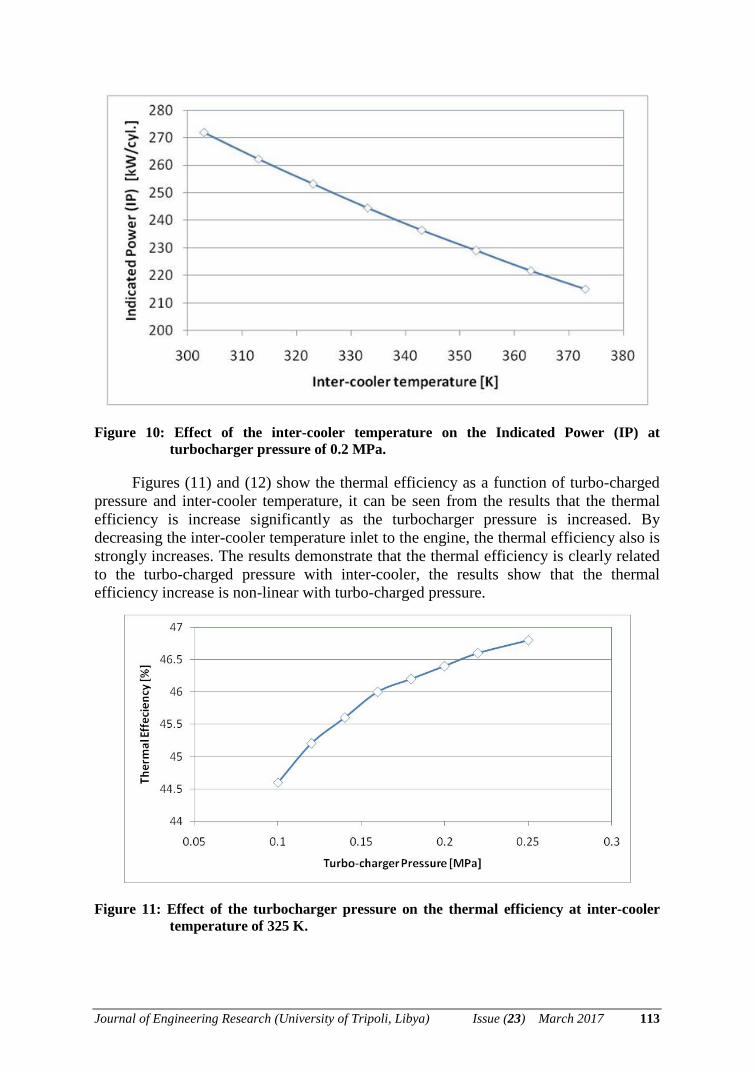
Figure 10: Effect of the inter-cooler temperature on the Indicated Power (IP) at
turbocharger pressure of 0.2 MPa.
Figures (11) and (12) show the thermal efficiency as a function of turbo-charged pressure and inter-cooler temperature, it can be seen from the results that the thermal efficiency is increase significantly as the turbocharger pressure is increased. By decreasing the inter-cooler temperature inlet to the engine, the thermal efficiency also is strongly increases. The results demonstrate that the thermal efficiency is clearly related to the turbo-charged pressure with inter-cooler, the results show that the thermal efficiency increase is non-linear with turbo-charged pressure.
Figure 11: Effect of the turbocharger pressure on the thermal efficiency at inter-cooler
temperature of 325 K.
Journal of Engineering Research (University of Tripoli, Libya) Issue (23) March 2017 113
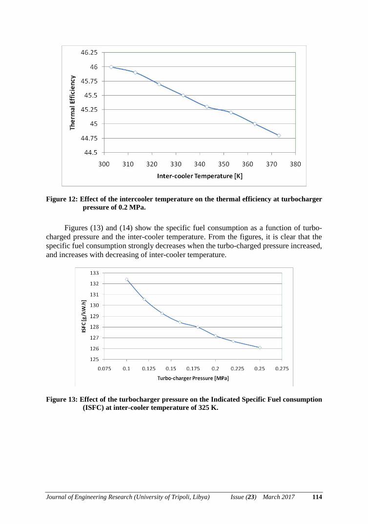
Figure 12: Effect of the intercooler temperature on the thermal efficiency at turbocharger
pressure of 0.2 MPa.
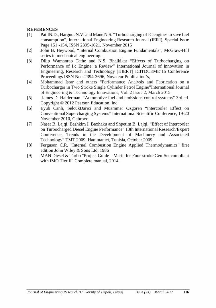
Figures (13) and (14) show the specific fuel consumption as a function of turbo-charged pressure and the inter-cooler temperature. From the figures, it is clear that the specific fuel consumption strongly decreases when the turbo-charged pressure increased, and increases with decreasing of inter-cooler temperature.
Figure 13: Effect of the turbocharger pressure on the Indicated Specific Fuel consumption
(ISFC) at inter-cooler temperature of 325 K.
Journal of Engineering Research (University of Tripoli, Libya) Issue (23) March 2017 114

Figure 14: Effect of the inter-cooler temperature on the Indicated Specific Fuel
Consumption (ISFC) at turbocharger pressure of 0.2 MPa.
CONCLUSIONS Modern diesel engines always use a turbocharger system with inter-cooler to
improve the engine performance. MAN B&W Diesel designed and successfully field-tested a package of suppressing the formation of soot in highly turbocharged engines. In this research, a four-stroke MAN Diesel & Turbo middle speed diesel engine was studied under the rating condition of 750 rpm and 135 kW/cyl. FORTRAN simulation was established to simulate the performance of the diesel engine under different operation conditions of turbo-charged pressure and inter-cooler temperature. Thermodynamic analysis of the turbocharged Diesel engine was based on the book "Internal Combustion Engine Applied Thermodynamics" By C.R. FERGUSON, [8]. The conclusions are; by keeping the equivalence ratio constant, the results show that the specific fuel consumption decreased with increasing the turbo-charged pressure, and by decreasing the inter-cooler temperature. The results also show that the indicated power was significantly increased with a turbocharging and intercooling, at turbocharger pressure of 0.25 MPa and with inter-cooler Temperature of 325K, the indicted power was increased more than 2.5 times, compared with the engine without turbo-charged (0.1 MPa).
Nomenclature
Abbreviation Description
RPM Revolution Per Minute
BDC Bottom Dead Centre
CA Crank Angle
TDC Top Dead Centre
DI Direct Injection
C I Compression Ignition
Journal of Engineering Research (University of Tripoli, Libya) Issue (23) March 2017 115
REFERENCES [1] PatilN.D., HargudeN.V. and Mane N.S. “Turbocharging of IC engines to save fuel
consumption”, International Engineering Research Journal (IERJ), Special Issue Page 151 -154, ISSN 2395-1621, November 2015
[2] John B. Heywood, “Internal Combustion Engine Fundamentals”, McGraw-Hill series in mechanical engineering.
[3] Dilip Wamanrao Tathe and N.S. Bhalkikar “Effects of Turbocharging on Performance of I.c Engine: a Review” International Journal of Innovation in Engineering, Research and Technology [IJIERT] ICITDCEME’15 Conference Proceedings ISSN No - 2394-3696, Novateur Publication’s,
[4] Mohammad Israr and others “Performance Analysis and Fabrication on a Turbocharger in Two Stroke Single Cylinder Petrol Engine”International Journal of Engineering & Technology Innovations, Vol. 2 Issue 2, March 2015.
[5] James D. Halderman. “Automotive fuel and emissions control systems” 3rd ed. Copyright © 2012 Pearson Education, Inc
[6] Eyub Canli, SelcukDarici and Muammer Ozgoren “Intercooler Effect on Conventional Supercharging Systems” International Scientific Conference, 19-20 November 2010, Gabrovo.
[7] Naser B. Lajqi, Bashkim I. Baxhaku and Shpetim B. Lajqi, “Effect of Intercooler on Turbocharged Diesel Engine Performance” 13th International Research/Expert Conference, Trends in the Development of Machinery and Associated Technology” TMT 2009, Hammamet, Tunisia, October 2009
[8] Ferguson C.R. "Internal Combustion Engine Applied Thermodynamics" first edition John Wiley & Sons Ltd, 1986
[9] MAN Diesel & Turbo "Project Guide – Marin for Four-stroke Gen-Set compliant with IMO Tier II" Complete manual, 2014.
Journal of Engineering Research (University of Tripoli, Libya) Issue (23) March 2017 116