The effect of dome properties on design of the axial ...
6
CHALLENGE JOURNAL OF STRUCTURAL MECHANICS 7 (1) (2021) 11–16 * Corresponding author. Tel.: +90-212-473-7070 ; Fax: +90-212-473-7180 ; E-mail address: [email protected] (A. E. Kayabekir) ISSN: 2149-8024 / DOI: https://doi.org/10.20528/cjsmec.2021.01.002 Research Article The effect of dome properties on design of axial symmetric reinforced concrete cylindrical walls Aylin Ece Kayabekir a, * a Department of Civil Enginering, İstanbul University-Cerrahpaşa, 34320 İstanbul, Turkey A B S T R A C T The usage of computer software in civil engineering has expanded in last decades. Many general-purpose and special-purpose commercial programs perform a very important function, especially at the design stage. In this study, a computer program is introduced for the analysis and design of the axial symmetric cylindrical wall con- sidering the dome effects. Analysis processes are carried out according to Flexibility theory with long wall assumption and during the reinforced concrete (RC) design of the wall, ACI 318-Building code requirements for structural concrete are considered. In numerical investigation, the effects of the dome properties (thickness and height) on the analysis and design of the wall are investigated by performing a totally 72 case analyzes. These cases include different support condition at bottom of the wall, wall heights, dome thicknesses and heights. According to analysis results, it is concluded that effects of dome thickness and heights on the wall on the wall are very limited. A R T I C L E I N F O Article history: Received 26 August 2020 Revised 9 October 2020 Accepted 23 October 2020 Keywords: Cylindrical wall Dome effect Flexibility theory Reinforced concrete design ACI 318 1. Introduction Shells are defined as structural members of which thick- ness is very small compared to other dimensions. These are several practical applications of these structural mem- bers such as places of worship, dams, water tanks etc. When the equations used in the analysis of these structural elements are derived by writing equilibrium equations on a small part of the shell, it is seen that these equations contain four integration constants depending on the boundary conditions. These integration constants need to be determined to solve the equations. For this reason, many scientific studies have been conducted on the solutions of these equations until today. One of the methods used in these alternative solutions is the theory of beams on elastic foundation. The situation that ena- bles this theory to be used in the cylindrical wall, is the similarity of the differential equations of the wall and beams. This situation has led to a rapid development in both scientific areas, as the analysis methods developed for the wall and can be used mutually. In this section, some important studies in the analysis methods of both structural members are summarized below. A first model for the beams on elastic foundation was proposed by Winkler in 1867. According to this model, foundation is represented by infinite number of inde- pendent springs are used. Between the reaction forces on the soil and the displacement of the beams at that point, there is a ratio which is equal to the spring coeffi- cient of the elastic springs. Also, it is assumed that the members that change shape under the applied load will return to their original state if the load is removed (Wang et al., 2005; Karaşin and Gülkan, 2008). Using this soil model, Winkler conducted stress analysis on rail- ways. In the analysis, the rails were defined with beams and the displacements were obtained by solving the dif- ferential equation. The integral coefficients in the displacement equation of the beam change with discontinuities in load distribu- tion on the beam. This situation makes the determina- tion of integral constants difficult. For that reason, vari- ous methods have been developed to overcome this problem. Initial parameter method developed by Uman- sky (1933) and the superposition method developed by Hetenyi (1936) are well known methods in scientific studies.
Transcript of The effect of dome properties on design of the axial ...

CHALLENGE JOURNAL OF STRUCTURAL MECHANICS 7 (1) (2021) 11–16
* Corresponding author. Tel.: +90-212-473-7070 ; Fax: +90-212-473-7180 ; E-mail address: [email protected] (A. E. Kayabekir)
ISSN: 2149-8024 / DOI: https://doi.org/10.20528/cjsmec.2021.01.002
Research Article
The effect of dome properties on design of
axial symmetric reinforced concrete cylindrical walls
Aylin Ece Kayabekir a,*
a Department of Civil Enginering, İstanbul University-Cerrahpaşa, 34320 İstanbul, Turkey
A B S T R A C T
The usage of computer software in civil engineering has expanded in last decades. Many general-purpose and special-purpose commercial programs perform a very
important function, especially at the design stage. In this study, a computer program
is introduced for the analysis and design of the axial symmetric cylindrical wall con-
sidering the dome effects. Analysis processes are carried out according to Flexibility
theory with long wall assumption and during the reinforced concrete (RC) design of
the wall, ACI 318-Building code requirements for structural concrete are considered. In numerical investigation, the effects of the dome properties (thickness and height)
on the analysis and design of the wall are investigated by performing a totally 72 case
analyzes. These cases include different support condition at bottom of the wall, wall
heights, dome thicknesses and heights. According to analysis results, it is concluded
that effects of dome thickness and heights on the wall on the wall are very limited.
A R T I C L E I N F O
Article history:
Received 26 August 2020
Revised 9 October 2020
Accepted 23 October 2020 Keywords:
Cylindrical wall
Dome effect
Flexibility theory
Reinforced concrete design
ACI 318
1. Introduction
Shells are defined as structural members of which thick-ness is very small compared to other dimensions. These are several practical applications of these structural mem-bers such as places of worship, dams, water tanks etc.
When the equations used in the analysis of these structural elements are derived by writing equilibrium equations on a small part of the shell, it is seen that these equations contain four integration constants depending on the boundary conditions. These integration constants need to be determined to solve the equations. For this reason, many scientific studies have been conducted on the solutions of these equations until today. One of the methods used in these alternative solutions is the theory of beams on elastic foundation. The situation that ena-bles this theory to be used in the cylindrical wall, is the similarity of the differential equations of the wall and beams. This situation has led to a rapid development in both scientific areas, as the analysis methods developed for the wall and can be used mutually. In this section, some important studies in the analysis methods of both structural members are summarized below.
A first model for the beams on elastic foundation was proposed by Winkler in 1867. According to this model, foundation is represented by infinite number of inde-pendent springs are used. Between the reaction forces on the soil and the displacement of the beams at that point, there is a ratio which is equal to the spring coeffi-cient of the elastic springs. Also, it is assumed that the members that change shape under the applied load will return to their original state if the load is removed (Wang et al., 2005; Karaşin and Gülkan, 2008). Using this soil model, Winkler conducted stress analysis on rail-ways. In the analysis, the rails were defined with beams and the displacements were obtained by solving the dif-ferential equation.
The integral coefficients in the displacement equation of the beam change with discontinuities in load distribu-tion on the beam. This situation makes the determina-tion of integral constants difficult. For that reason, vari-ous methods have been developed to overcome this problem. Initial parameter method developed by Uman-sky (1933) and the superposition method developed by Hetenyi (1936) are well known methods in scientific studies.
12 Kayabekir / Challenge Journal of Structural Mechanics X (X) (XXXX) X–X
The book written by Hetenyi in 1946 is one of the most important sources on this subject. Some other im-portant books on this subject were written by Henry (1956), Jones (1997), Melerski (2000). Information on many solution methods can be found in these books. Apart from these, there are many methods published in various sources regarding the solution of the beams on elastic ground (Vianello, 1898; Cross, 1930; Levinton, 1947; Penzien, 1960; Miranda and Nair, 1966; Beaufait, 1977; Ting, 1982; Yankelevsky et al., 1989).
In the book called thin sell structures written by Bil-lington in 1965, beam-wall similarity in the solution of the differential equation and flexibility theory in the analysis were used. Except this, the studies done by Bekdaş (2015; 2018; 2019) can be also given as examples for the analysis of the axial symmetric cylindrical walls.
In this study, a computer program has been devel-oped for the design and analysis of the axial symmetric cylindrical wall considering the dome effects. Flexibility theory was used in the wall analyzes performed accord-ing to the long wall assumption. During the reinforced concrete design, rules of ACI 318 regulation are used. As numerical examples, totally 72 case analyses are done in order to observe effect of dome on design and analysis of
the wall. In these cases, different support condition at the bottom and dome properties at the upper section for dif-ferent wall height are investigated.
2. Analysis and Design Process
Analysis and design process of the axial symmetric cy-lindrical walls can be summarized with two main stages. First stage is entering the data of structure. These data contain geometrical and sectional properties for wall and dome (thickness, height, radius, etc.), material prop-erties (elasticity modulus, Poisson’s ratio, etc), support conditions of the bottom section wall and unit material cost for concrete and steel. In the second stage wall with dome calculations are performed. These calculations are done in three steps. These steps are: Calculation of the wall displacements and internal
forces; RC design of the wall in accordance with ACI 318 re-
quirements; Determination of total wall material cost concrete and
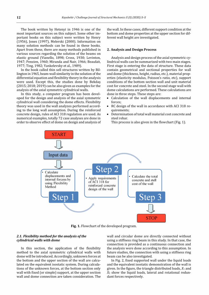
steel rebar. This process is also given in the flowchart (Fig. 1).
Fig. 1. Flowchart of the developed program.
2.1. Flexibility method for the analysis of the cylindrical walls with dome
In this section, the application of the flexibility method to the axial symmetric cylindrical walls with dome will be introduced. Accordingly, unknown forces at the bottom and the upper section of the wall are calcu-lated on the equivalent isostatic system. During calcula-tions of the unknown forces, at the bottom section only wall with fixed (or simple) support, at the upper section wall and dome connection are taken consideration. The
wall and circular dome are directly connected without using a stiffness ring beam in this study. In that case, the connection is provided as a continuous connection and the analysis were done according to this assumption. In future studies, the connection with using a stiffness ring beam can be also investigated.
In Fig. 2, fixed supported wall under the liquid loads and the equivalent isostatic demonstration of the wall is given. In the figure, the triangle distributed loads, X1 and X2 show the liquid loads, lateral and rotational redun-dant forces respectively.

Kayabekir / Challenge Journal of Structural Mechanics X (X) (XXXX) X–X 13
Fig. 2. Fixed supported cylindrical wall and equivalent isostatic system of the wall.
The redundant forces can be easily found by compat-ibility equations of system. For the fixed supported cy-lindrical walls, since there is no relative displacement at the support point, compatibility equations can be writ-ten as in Eq. (1).
𝐷10 + 𝐹11𝑋1 + 𝐹12𝑋2 = 0 and
𝐷20 + 𝐹22𝑋2 + 𝐹21𝑋2 = 0 (1)
In Eq. (1), D10 and D20 represent the displacements due to external loads in the freedoms corresponding to X1 and X2, respectively. F11, F12, F21 and F22 show flexibil-ity coefficients. These flexibility terms indicate the dis-placement in the freedom indicated by the first subscript in case of a unit force applied to the freedom indicated by the second subscript.
The lateral (D10) and rotational displacements (D20) can be found by;
𝐷10 = −𝛾𝑟2𝐻
𝐸ℎ 𝑎𝑛𝑑 𝐷20 =
𝛾𝑟2
𝐸ℎ (2)
where γ, r, H, E and h are density of liquid, radius of the wall, wall height, elasticity modulus and wall thickness respectively.
Flexibility coefficients can be calculated as in Eq. (3).
𝐹11 =1
2𝛽3𝐷 , 𝐹22 =
1
𝛽𝐷 𝑎𝑛𝑑 𝐹12 = 𝐹21 = −
1
2𝛽2𝐷 (3)
In Eq. (3), 𝛽 and D are parameters (Eq. 4), including rigidity and geometrical properties, and flexural rigidity (Eq. 5) respectively.
𝛽 = √𝐸ℎ
4𝑟2𝐷
4= √3(1−𝜈2)
𝑟2ℎ2
4
(4)
𝐷 =𝐸ℎ3
12(1−𝜈2) (5)
In Eqs. (4-5), 𝜈 represent Possion’s ratio. If Eqs. (2-5) are implemented in Eq. (1), redundant forces will be;
[𝑋1
𝑋2] = 𝐹−1 [
−𝛾∙𝑟2∙𝐻
𝐸∙ℎ
𝛾∙𝑟2
𝐸∙ℎ
] (6)
As mentioned before for the calculations at the upper section, wall and dome are considered together. The dis-placement and flexibility terms for the dome written as;
𝐷10𝑑 =𝑟𝑑
2𝑞
𝐸𝑑ℎ𝑑(
1+𝜈𝑑
1+𝑐𝑜𝑠 𝛼− 𝑐𝑜𝑠 𝛼) 𝑠𝑖𝑛 𝛼 𝑎𝑛𝑑
𝐷20𝑑 =𝑟𝑑𝑞
𝐸𝑑ℎ𝑑(2 + 𝜈𝑑) 𝑠𝑖𝑛 𝛼 (7)
𝐹11𝑑 =2𝑟𝑑𝜆𝑑 𝑠𝑖𝑛2 𝛼
𝐸𝑑ℎ𝑑 , 𝐹12𝑑 = 𝐹21𝑑 =
2𝜆𝑑2 𝑠𝑖𝑛 𝛼
𝐸𝑑ℎ𝑑 𝑎𝑛𝑑
𝐹22𝑑 = 4𝜆𝑑
3
𝐸𝑑ℎ𝑑𝑟𝑑 (8)
where the terms represent rd, radius; 𝜈d, Poisson ratio; α, starting angle; Ed, modulus of elasticity; hd, thickness of the dome; λd, a constant parameter including rigidity, ge-ometrical properties; and q, distributed load on the dome.
The wall terms previously calculated for the bottom section is also valid for upper section. After by superpos-ing of the wall and dome terms, the redundant forces can be calculated;
[𝑋3
𝑋4] = 𝐹𝑠
−1 [𝐷10𝑠
𝐷20𝑠] (9)
For further detailed information can be found in ref-erence book of Billington (1965).
2.2. Reinforced concrete design of the cylindrical wall
In this section, design constants of the problem are summarized. According to the regulation of ACI 318-Building code requirements for structural concrete, these constraints are listed in the Table 1. As seen from the table, mainly these requirements are related to sec-tions capacities and limits for area and orientation of re-inforcement design.
3. Numerical Investigation
In this section, several numerical cases including dif-ferent wall support condition and wall height, dome thickness and height are presented in order to investi-gate the effect of dome properties on cylindrical wall

14 Kayabekir / Challenge Journal of Structural Mechanics X (X) (XXXX) X–X
analyses and design. Totally 72 cases are considered. In these cases, fixed and simple support at the bottom of the wall, 5-7 m for wall height, 2.5 m and 4.5 m dome heights and 0.2-0.3m dome thickness (0.02 m increment) are used. The other design parameters of the problem are presented in the Table 2.
Table 1. Design constraints.
Description Constraints
Flexural strength capacity, Md Md ≥Mu
Shear strength capacity, Vd Vd ≥ Vu
Minimum steel ratio, ρmin As≥ Asmin
Maximum steel bars spacing, Smax S ≤ Smax
Minimum steel bars spacing, Smin S ≥ Smin
Minimum concrete cover, ccmin ccmin ≥ 40 mm
Table 2. Design parameters for cases.
Definition Value
Radius of wall, R (m) 8
Height of the wall, H (m) 5-7
Yield strength of steel, fy (MPa) 420
Concrete cover, cc (mm) 50
Compressive strength of concrete, f΄c (MPa) 30
Elasticity modulus of concrete, Ec (MPa) 4700(f΄c)1/2
Poisson ratio of concrete, ν 0.2
Density of liquid, γ (kN/m3) 7
Minimum reinforcement ratio, min 0.008
Unit concrete cost, Cc (TL/m3) 200
Unit steel cost, Cs, TL/ton 5000
3.1. Simple support cases
This section presents the effects of the thickness (hd) and height (Hd) of the dome on longitudinal moments and design for the simple supported cylindrical wall. For this purpose, the analyses of 36 different cases are con-ducted. An iterative way is followed during determining the wall thicknesses used in the analyzes. The minimum wall thickness, which provides all design constraints, is used in the design by repeating the analyzes for each wall height (H). In this way, it is aimed to find more eco-nomical results in terms of cost. Accordingly, the thick-ness values for the heights of 5m, 6m and 7m were ob-tained as 0.25, 0.3 and 0.35 m, respectively.
In Fig. 3, each graph corresponds the longitudinal moment distribution according to six different dome thicknesses for a constant wall and dome height.
When each wall height cases are evaluated within it-self, by considering different dome thicknesses it is seen that the differences between the maximum moment on the wall and the moment at the junction point of the wall-dome are relatively small. At points with maximum mo-ments it is understood that this difference is below 0.07% and this difference also does not change the wall design as well as material cost of the wall. A similar situ-ation is valid for the height of the dome. The maximum difference depending on the height of the dome was found to be 0.22%.
Therefore, it is concluded that the effect of both dome thickness and height on the analysis and design is quite limited for the analyzed cases.
Fig. 3. Simple supported wall height-longitudinal moment graphs for different cases.
Kayabekir / Challenge Journal of Structural Mechanics X (X) (XXXX) X–X 15
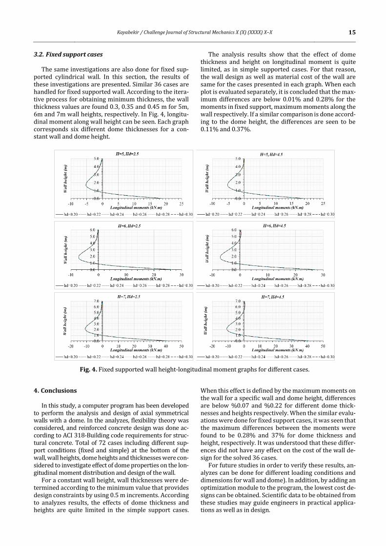
3.2. Fixed support cases
The same investigations are also done for fixed sup-ported cylindrical wall. In this section, the results of these investigations are presented. Similar 36 cases are handled for fixed supported wall. According to the itera-tive process for obtaining minimum thickness, the wall thickness values are found 0.3, 0.35 and 0.45 m for 5m, 6m and 7m wall heights, respectively. In Fig. 4, longitu-dinal moment along wall height can be seen. Each graph corresponds six different dome thicknesses for a con-stant wall and dome height.
The analysis results show that the effect of dome thickness and height on longitudinal moment is quite limited, as in simple supported cases. For that reason, the wall design as well as material cost of the wall are same for the cases presented in each graph. When each plot is evaluated separately, it is concluded that the max-imum differences are below 0.01% and 0.28% for the moments in fixed support, maximum moments along the wall respectively. If a similar comparison is done accord-ing to the dome height, the differences are seen to be 0.11% and 0.37%.
Fig. 4. Fixed supported wall height-longitudinal moment graphs for different cases.
4. Conclusions
In this study, a computer program has been developed to perform the analysis and design of axial symmetrical walls with a dome. In the analyzes, flexibility theory was considered, and reinforced concrete design was done ac-cording to ACI 318-Building code requirements for struc-tural concrete. Total of 72 cases including different sup-port conditions (fixed and simple) at the bottom of the wall, wall heights, dome heights and thicknesses were con-sidered to investigate effect of dome properties on the lon-gitudinal moment distribution and design of the wall.
For a constant wall height, wall thicknesses were de-termined according to the minimum value that provides design constraints by using 0.5 m increments. According to analyzes results, the effects of dome thickness and heights are quite limited in the simple support cases.
When this effect is defined by the maximum moments on the wall for a specific wall and dome height, differences are below %0.07 and %0.22 for different dome thick-nesses and heights respectively. When the similar evalu-ations were done for fixed support cases, it was seen that the maximum differences between the moments were found to be 0.28% and 37% for dome thickness and height, respectively. It was understood that these differ-ences did not have any effect on the cost of the wall de-sign for the solved 36 cases.
For future studies in order to verify these results, an-alyzes can be done for different loading conditions and dimensions for wall and dome). In addition, by adding an optimization module to the program, the lowest cost de-signs can be obtained. Scientific data to be obtained from these studies may guide engineers in practical applica-tions as well as in design.

16 Kayabekir / Challenge Journal of Structural Mechanics X (X) (XXXX) X–X
Publication Note
This research has previously been presented at the 6th International Conference on Harmony Search, Soft Com-puting and Applications (ICHSA 2020) held in İstanbul, Turkey, on July 16-17, 2020. Extended version of the re-search has been submitted to Challenge Journal of Struc-tural Mechanics and has been peer-reviewed prior to the publication.
REFERENCES
Beaufait FW (1977). Numerical Analysis of beams on elastic founda-
tions. Journal of the Mechanics Division Proceedings of the ASCE, 103,
205-209. Bekdaş G (2015). Harmony search algorithm approach for optimum
design of post-tensioned axially symmetric cylindrical reinforced
concrete walls. Journal of Optimization Theory and Applica-tions, 164(1), 342-358.
Bekdaş G (2018). New improved metaheuristic approaches for opti-
mum design of posttensioned axially symmetric cylindrical rein-forced concrete walls. The Structural Design of Tall and Special
Buildings, 27(7), e1461.
Bekdaş G (2019). Optimum design of post‐tensioned axially symmetric cylindrical walls using novel hybrid metaheuristic methods. The
Structural Design of Tall and Special Buildings, 28(1), e1550.
Billington DP (1965). Thin Shell Structures. McGraw-Hill, New York. Cross H (1930). Analysis of continuous frames by distributing fixed-
end moments. Proceeding of the ASCE, 57, 919-928.
Henry FDC (1956). The Design and Construction of Engineering Foun-dations. Mc-Graw Hill, New York.
Hetenyi M (1936). Analysis of bars on elastic foundation. Final Report
of the second International Congress for Bridge and structural Engi-neering (English Edition), October Berlin- Munich, Verlag von Wil-
helm Ernst and Son, 846-851.
Hetenyi M (1946). Beams on Elastic Foundation. The University of Michigan Press, Ann Arbor.
Jones G (1997). Analysis of Beams on Elastic Foundations using Finite
Difference Theory. Thomas Telford Publishing, New York. Karaşin HA, Gülkan P (2008). Elastik zeminlere oturan plakların sonlu
ızgara yöntemi ile yaklaşık çözümü. Teknik Dergi, 293, 4445-4454.
(in Turkish) Levinton Z (1947). Elastic foundation analysed by the method of re-
dundant reactions. Journal of the Structural Division, Proceedings of
the ASCE, 73, 1529-1541. (also in Transactions ASCE, 114, 40-52). Melerski ED (2000). Design Analysis of Beams. Circular Plates and Cy-
lindrical Tanks on Elastic Foundations. Taylor & Francis Group,
London. Miranda C, Nair K (1966). Finite beams on elastic foundation. Journal
of the Structural Division, Proceedings of the ASCE, 92, 131-142.
Penzien J (1960). Discontinuity stresses in beams on elastic foundation. Journal of the Structural Division, Proceeding of the ASCE, 86, 67-97.
Ting BY (1982). Finite beams on elastic foundation with restraints.
Journal of the Structural Division, Proceedings of the ASCE, 108, 611-621.
Umansky AA (1933). Analysis of Beams on Elastic Foundation. Central
Research Institute of Auto-Transportation, Leningrad. Vianello L (1898). Graphische Untersuchungen der knickfestigkeit
gerader stabe. Zeitschrift des Vereins Deutscher Ingenieure, 42,
1436-1443. (in German) Wang YH, Tham LG, Cheung YK (2005). Beams and plates on elastic
foundations: a review. Progress in Structural Engineering and Mate-
rials, 7,174–182. Winkler E (1867). Die Lehre von der Elasticitaet und Festigkeit – mit
besonderer Rücksicht auf ihre Anwendung in der Technik. Für pol‐
ytechnische Schulen, Bauakademien, Ingenieure, Maschinenbauer, Architekten, etc., Verlag H. Dominicus, Prag. (in German)
Yankelevsky DZ, Eisenberger M, Adin MA (1989). Analysis of beams on
nonlinear winkler foundation. Computer and Structures, 31, 287-292.


![AXIAL FATIGUE PROPERTIES OF LEAN Fe-Mo-Ni ALLOYS › ... › axial-fatigue-properties-of-lean-fe-mo-ni-alloys.pdftherefore beneficial to fatigue performance [7] [8]. It is also known](https://static.fdocuments.us/doc/165x107/5f0e5d3e7e708231d43ee330/axial-fatigue-properties-of-lean-fe-mo-ni-alloys-a-a-axial-fatigue-properties-of-lean-fe-mo-ni-.jpg)