The Direction of Fluid Dynamics for Liquid Propulsion at ... · PDF fileThe Direction of Fluid...
45
The Direction of Fluid Dynamics for Liquid Propulsion at NASA Marshall Space Flight Center Presented by Lisa W. Griffin Chief, Fluid Dynamics Branch – ER42 NASA Marshall Space Flight Center [email protected] Advances in Rocket Engine Modeling and Simulation, and its Future Tokyo, Japan September 26 – 27, 2012 https://ntrs.nasa.gov/search.jsp?R=20130008752 2018-05-09T03:24:23+00:00Z
-
Upload
phungtuong -
Category
Documents
-
view
213 -
download
0
Transcript of The Direction of Fluid Dynamics for Liquid Propulsion at ... · PDF fileThe Direction of Fluid...

The Direction of Fluid Dynamics for Liquid Propulsion at NASA Marshall
Space Flight CenterPresented by Lisa W. Griffin
Chief, Fluid Dynamics Branch – ER42NASA Marshall Space Flight Center
Advances in Rocket Engine Modeling and Simulation, and its FutureTokyo, Japan
September 26 – 27, 2012
https://ntrs.nasa.gov/search.jsp?R=20130008752 2018-05-09T03:24:23+00:00Z

NASA MARSHALL SPACE FLIGHT CENTER
Marshall Space Flight Center (MSFC) is one of ten NASA field centers. MSFC supports the Agency goals of lifting from Earth, living and working in space, and understanding our world and beyond by providing propulsion, space transportation, space systems, and scientific research.
Page 2
MSFC
MSFC is the NASA-designated center for the development of space launch systems. The center is particularly well-known for propulsion system development
MSFC is the NASA-designated center for the development of space launch systems. The center is particularly well-known for propulsion system development
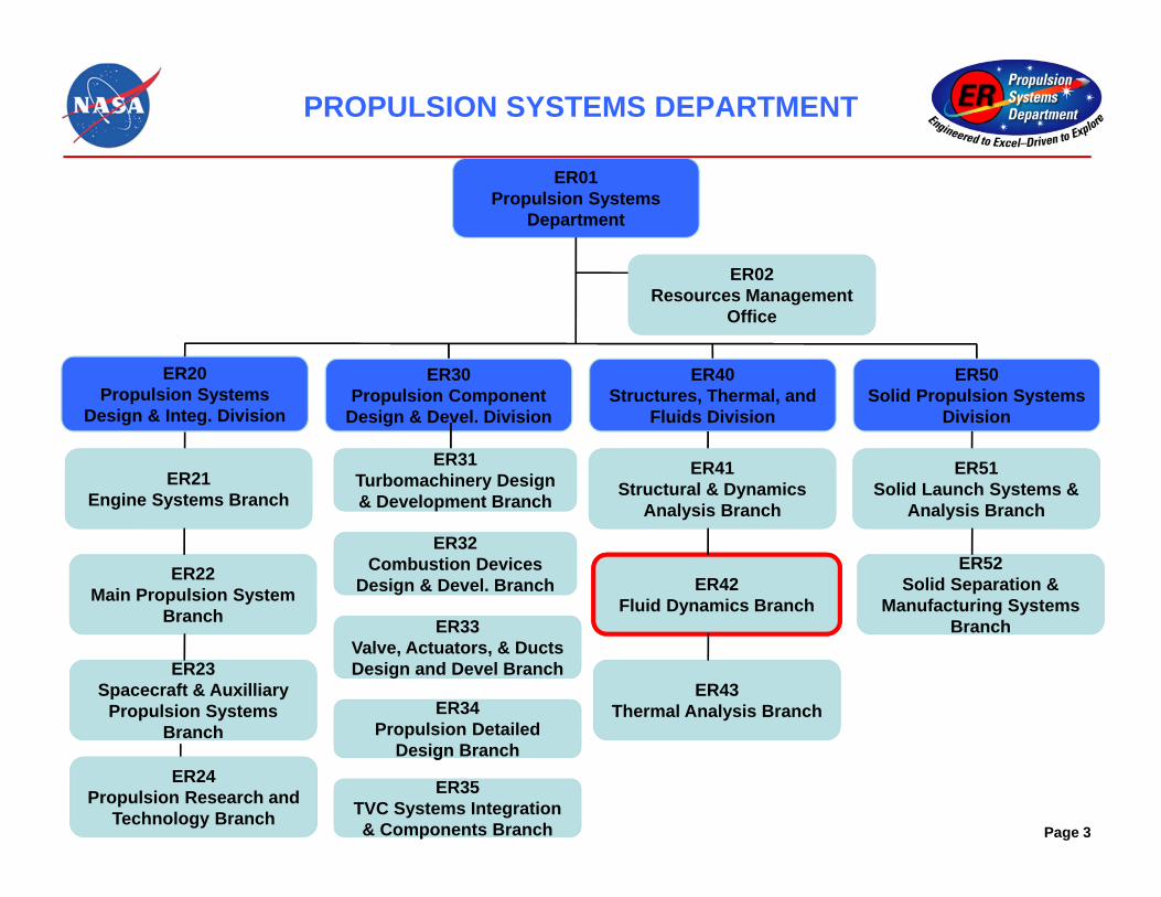
PROPULSION SYSTEMS DEPARTMENT
Page 3
ER01Propulsion Systems
Department
ER02Resources Management
Office
ER20Propulsion Systems
Design & Integ. Division
ER30Propulsion Component
Design & Devel. Division
ER30Propulsion Component
Design & Devel. Division
ER40Structures, Thermal, and
Fluids Division
ER40Structures, Thermal, and
Fluids Division
ER50Solid Propulsion Systems
Division
ER50Solid Propulsion Systems
Division
ER21Engine Systems Branch
ER22Main Propulsion System
Branch
ER23Spacecraft & Auxilliary
Propulsion Systems Branch
ER31Turbomachinery Design & Development Branch
ER31Turbomachinery Design & Development Branch
ER32Combustion Devices
Design & Devel. Branch
ER32Combustion Devices
Design & Devel. Branch
g
ER33Valve, Actuators, & Ducts Design and Devel Branch
ER41Structural & Dynamics
Analysis Branch
ER42Fluid Dynamics Branch
ER43Thermal Analysis Branch
ER51Solid Launch Systems &
Analysis Branch
ER52Solid Separation &
Manufacturing Systems Branch
ER24Propulsion Research and
Technology Branch
g
ER34Propulsion Detailed
Design Branch
p
ER35TVC Systems Integration & Components Branch

FLUID DYNAMIC BRANCH STRUCTURE
Page 4
Fluid Dynamics BranchBranch Chief – Lisa Griffin
Assistant Branch Chief – Tom NesmanTechnical Assistant – Denise Chaffee
Computer System Administrator – Dennis Goode
Propellant Delivery CFDTeam Leader: Jeff West
Experimental and Unsteady Flows
Team Leader: Tom Zoladz
Acoustics and StabilityTeam Leader: Vacant
Combustion Driven CFDTeam Leader: Kevin Tucker
ER42 is comprised of four teams of approximately forty-five employees
ER42 is comprised of four teams of approximately forty-five employees

FLUID DYNAMICS BRANCH APPLICATIONS
The Fluid Dynamics Branch (ER42) is responsible for all aspects of the discipline of fluid dynamics applied to propulsion or propulsion-induced loads and environments. This work begins with design trades and parametric studies, and continues through development, risk assessment, anomaly investigation and resolution, and failure investigations.Because of the skills in the branch, ER42 also works non-propulsion items such as for telescopes and payload racks on an as needed basis.
Page 5
Main Propulsion System Turbopumps Liquid Combustion Devices Solid Rocket Motors
Coupled SystemsLaunch, Separation, and
Plume-Induced Environments and Debris
• Tank Dynamics• Cryofluid Management• Feedline Flow Dynamics• Valve Flow and Dynamics
• Pump Dynamics • Turbine Dynamics
• Injection Dynamics• Chamber Acoustics• Combustion Stability• Nozzle Dynamics
• Motor Dynamics• Nozzle Dynamics• Combustion Stability
• Feed System Dynamics• Coupled Pump/MPS
Dynamics, e,g,, Pogo• Thrust Oscillations and its
Impact on the Vehicle•Tank Slosh and its Impact on Vehicle Stability and GN&C
• Liftoff Acoustics• Separation Acoustics• Overpressure• Inflight Plume Generated Noise• Noise Mitigation• Hydrogen Entrapment• Liftoff Debris Transport
ER42 is a Discipline-Centric branch, not analysis-centric or test-centric. Integration of all discipline methods into one branch enables efficient and accurate support to the projects.
ER42 is a Discipline-Centric branch, not analysis-centric or test-centric. Integration of all discipline methods into one branch enables efficient and accurate support to the projects.

FLUID DYNAMICS ANALYSIS
Page 6
…
NCmm
dtdPPP
21
21 ;
N
N
LPmRP
dtmdmm 32
32 ;
Scaling MethodsScaling Methods
, ,
, ,
, ,
, ,
sin ( )( )
sin( ) cos( )
( )
sin ( )( )
sin( ) cos( )
T o T f
T f g T f
T f T o
T o g T o
Xx
y
Fz
0 100 200 300 400 500 600 700 800 900 10000
1
2
3
4
5System Bode Plot
Frequency [Hz]
Ope
n-Lo
op G
ain
[-]
0 100 200 300 400 500 600 700 800 900 1000-200
-100
0
100
200
Frequency [Hz]
Ope
n-Lo
op P
hase
[deg
]
Gain / Phase PlotsGain / Phase Plots
Lump Parameter ModelingLump Parameter Modeling
System Stability ModelingSystem Stability Modeling
Finite Element ModelingFinite Element Modeling
Computational Fluid Dynamics
Computational Fluid Dynamics
ER42 conducts all levels of fluid dynamics analysis from scaling methods through 3D Unsteady CFD
ER42 conducts all levels of fluid dynamics analysis from scaling methods through 3D Unsteady CFD

FLUID DYNAMICS TESTING
Page 7
0.00
0.05
0.10
0.15
0.20
0.25
0.30
0.35
0.40
0.45
0.50
0.0 20.0 40.0 60.0 80.0 100.0
x/bx
Ps/P
t
Maximum Moments at each NPR Bin for TIC4, theJ2-X Simulant, and PAR_SSME, the SSME Simulant
6325
9730
0
1000
2000
3000
4000
5000
6000
7000
8000
9000
10000
10 20 30 40 50 60 70 80 90 100 110 120
NPR
Mom
ent (in-
lbf)
TIC4(J2X) Smooth Wall
PAR_SSME
Cold flow testing in
Nozzle Test Facility
Cold flow testing in
Nozzle Test Facility
WateflowTesting in
Pump Facility
WateflowTesting in
Pump Facility
Airflow Testing in Turbine Facility
Airflow Testing in Turbine Facility
Scale Model Acoustics Testing
Scale Model Acoustics Testing
Engine and Component
Testing
Engine and Component
Testing
Solid Rocket Testing
Solid Rocket Testing
ER42 conducts and supports testing for hardware and technology development and verification, and analysis validation• Primary responsibility for cold flow
and scale model acoustics tests• Secondary responsibility for hotsystem and component testing
ER42 conducts and supports testing for hardware and technology development and verification, and analysis validation• Primary responsibility for cold flow
and scale model acoustics tests• Secondary responsibility for hotsystem and component testing

MAIN PROPULSION SYSTEM
Page 8
Tank Ullage Pressure Valve
Tank Ullage Pressure Valve
LOX TankLOX Tank
Articulating Feedline
Articulating Feedline
Engine Interface
Tank Exit
The Main Propulsion System (MPS) is defined as the propellant delivery system from Tank to Engine Interface.
• Tank with all of its internal components• Valves• Feedlines with all of its internal components
ER42’s primary analysis tool for MPS is CFD
The Main Propulsion System (MPS) is defined as the propellant delivery system from Tank to Engine Interface.
• Tank with all of its internal components• Valves• Feedlines with all of its internal components
ER42’s primary analysis tool for MPS is CFD

LIQUID PROPELLANT TANKS - SLOSH
Page 9
Slosh Frequency of a 1/3.75 Scale Model of Centaur LOX Tank
0.4
0.6
0.8
1
1.2
1.4
1.6
0 0.2 0.4 0.6 0.8 1Liquid Depth Ratio h/(b+c)
Freq
uenc
y Pa
ram
ter
Present CFD-SimulationExperimental Data
Earth to Orbit Simulation
Improvement to Classic Mass-Spring Model
ER42 performs high fidelity CFD analysis of complex geometry and/or complex accelerated propellant tank sloshing to determine slosh modes and their respective frequencies, amplitudes, and damping characteristics
ER42 performs high fidelity CFD analysis of complex geometry and/or complex accelerated propellant tank sloshing to determine slosh modes and their respective frequencies, amplitudes, and damping characteristics
Next challenges with future simulations include implementation of massively parallel gas-liquid interface tracking methods and efficient hybrid implicit/explicit methods to address disparate time-stepping requirements
Next challenges with future simulations include implementation of massively parallel gas-liquid interface tracking methods and efficient hybrid implicit/explicit methods to address disparate time-stepping requirements

LIQUID PROPELLANT TANKS –PRESSURIZATION AND DRAIN
Page 10
temperature Helium concentration
Assessment of Anti-Vortex Baffle Design
LH2 Tank Pre-press Analysis
Tank Pressurization• Flow through diffuser• Interaction of ullage gas with propellant
surface (mass transfer, multiphase heat transfer, surface evaporation, chemical species)
Tank Drain• Analysis of vortical flow in pipe• Assessment of anti-vortex baffle efficiency
Tank Pressurization• Flow through diffuser• Interaction of ullage gas with propellant
surface (mass transfer, multiphase heat transfer, surface evaporation, chemical species)
Tank Drain• Analysis of vortical flow in pipe• Assessment of anti-vortex baffle efficiency
Near Term Work• Validation of robust method
for simulating mass transfer across the gas-liquid interface
Near Term Work• Validation of robust method
for simulating mass transfer across the gas-liquid interface

VALVES
Page 11
Still Images of Mach Number as Valve Closes
Time-accurate Forces on Poppet During Valve Stroke
Time-accurate Pressure Oscillations During Valve Stroke
Still Images of Mach Number as Valve Re-opens
ER42 conducts high fidelity CFD simulations of valves to predict fluid flow patterns, mean pressure drops, and unsteady fluid environments
ER42 conducts high fidelity CFD simulations of valves to predict fluid flow patterns, mean pressure drops, and unsteady fluid environments
Future work aimed at implementation of valve component force and friction models
Future work aimed at implementation of valve component force and friction models
Partially Open Liquid Fuel and Oxidizer Ball Valves
Valv
e R
esis
tanc
e C
oeffi
cien
t
Valve Position [Valve Open Fraction]
Tranisent 3D Simulation of Poppet Valve

POPPET VALVE ANIMATION
Page 12

FEEDLINES
Page 13
0.70
0.75
0.80
0.85
0.90
0.95
1.00
1.05
1.10
1.15
1.20
-1.0 -0.8 -0.6 -0.4 -0.2 0.0 0.2 0.4 0.6 0.8 1.0
Non
dim
ensi
onal
ized
Vel
ocity
Span
CFD Data
Station 700
270o 90o
LAB DATA
CFD16.7 Hz
Data16.3 Hz
ER42 performs high fidelity CFD simulations of liquid propellant feedlines to predict pressure drops through bends, articulating joints, and splits, flow uniformity dues to bends and wakes, and unsteady pressure environments
ER42 performs high fidelity CFD simulations of liquid propellant feedlines to predict pressure drops through bends, articulating joints, and splits, flow uniformity dues to bends and wakes, and unsteady pressure environments
Waterflow Test Article
Velocity Profiles
CFD Predictions
Harmonic Analysis of Pressure Tap Data

TURBOPUMPS
Page 14
ER42 supports the design, development, and certification of high-speed turbomachinery Quick turnaround CFD design parametrics Time-accurate rotor-stator CFD analysis Highly instrumented pump waterflow test Component and engine test support
ER42 supports the design, development, and certification of high-speed turbomachinery Quick turnaround CFD design parametrics Time-accurate rotor-stator CFD analysis Highly instrumented pump waterflow test Component and engine test support
Turbine Airflow Rotating AssemblyPump Waterflow Test Article
Hotfire Engine Test
Turbine Unsteady CFD Analysis Pump Unsteady CFD Analysis

TURBOPUMPS – TURBINE ANALYSIS
Page 15
~550 Million Grid Cells
Toroidal inlet manifold causes significant distortions of unsteady forcing functions in downstream blade rows
Unsteady Loads Development All flow features which significantly modify fluid forcing functions of interest must be modeled Must show spatial and temporal resolution of unsteady forcing functions. Full 360 degrees models are necessary for most rocket turbines due to
large regions of separated flow. Periodic models corrupt the unsteady forcing functions and are not sufficient.
Spatially Resolved First Rotor
Fuel Turbine Computational DomainInstantaneous Pressure
Contours
Instantaneous Entropy Contours
Vortex Shedding
Highly Separated Flow
Expansion Wave
Bow Shock

TURBOPUMPS – TURBINE ANALYSIS
Page 16
Unsteady Loads Delivery Unsteady pressure history saved at all points of all blade
surfaces Must show spatial and temporal resolution of unsteady forcing functions Unsteady pressure histories from blade surfaces are
interpolated onto stress grids for structural analysis. Allblades must be used if rotor-rotor or stator-stator effects areto be captured Unsteady pressures may be delivered in temporal or
frequency domains
Instantaneous Unsteady Pressure Fuel Turbine
CFD SolutionStress Grid
Pressure Interpolation onto Stress Grid

TURBINE AIRFLOW TESTING
Page 172 x IGV 3 x IGV 4 x IGV 5 x IGV
Pre
ssur
e {p
si}
Frequency {Hz}
Fourier Transforms of First Stage Blade Suction Side at 13% Axial Chord and 50% Span Location Highly Instrumented Turbine Test Article
On Shaft Data Acquisition System
Testing of Highly Instrumented Turbine Models in Scaled Air Conditions Steady and unsteady pressure loadings Interstage cavity pressures Performance mapping over a wide range CFD validation

PUMP WATERFLOW TESTING
Page 18
Comprehensive steady and unsteady pump performance is evaluated at scaled engine operating conditions. Dense instrumentation suites, velocimetry, and flow visualization are utilized in mapping pump characteristics.
Low pressure pump with upstream main propulsion system element simulation
2-blade inducer with on-rotor dynamic force measurement system
PUMP WATERFLOW TESTING
Page 19
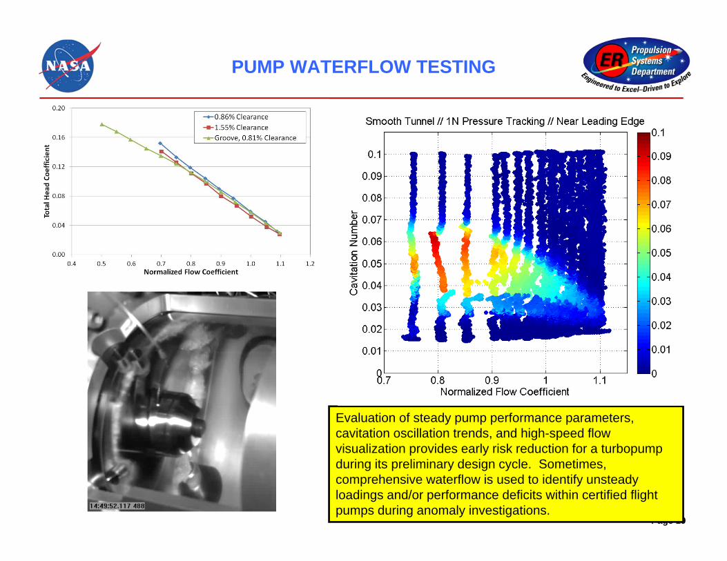
Evaluation of steady pump performance parameters, cavitation oscillation trends, and high-speed flow visualization provides early risk reduction for a turbopumpduring its preliminary design cycle. Sometimes, comprehensive waterflow is used to identify unsteady loadings and/or performance deficits within certified flight pumps during anomaly investigations.

PUMP CFD
Page 20
Time accurate CFD provides insight into the complex flow field behind higher order cavitation. Higher order cavitation is a potential forcing function for primary inducer bending modes.
Non-cavitating CFD is used to identify critical unsteady flow interactions between inducer blades and cavitation suppression grooves. These interactions are thought to promote higher order cavitation oscillations within the cavitating turbopump. The time-accurate CFD predicts slowly rotating/high cell count progressions very similar to higher order cavitation instabilities measured in waterflow test.
CFD calculations effectively capture tip vortex dynamics for inducers operating with minimal tip clearance (without cavitation suppressor).

IMMERSED DAMPING
Page 21
The suppression of lower order cavitation oscillations may bring about higher order flow instabilities which can resonate primary inducer blade modes of vibration. A combination of CFD and experiment is being used to understand the significance of immersed blade damping. Our system damping prediction capability is evolving in a rigorous manner validated by experiment.
Immersed damping is evaluated under no-flow conditions by experiment and with CFD under modally accurate blade motion. System damping is measured via modal test, and the oscillatory damping forces are extracted from the CFD prediction.
Higher order cavitation oscillation coincides in frequency and modal shape with primary vibration modes of inducers. Can immersed blade damping provide us fatigue margin?

IMMERSED DAMPING
Page 22
This combined Fluid Mechanics-Experimental effort showcases our disciplined penetration of complex propulsion system dynamic environments.
CFD-based simulation of 2-blade inducer displacing water at high frequency. Damping is
developed via the formation of flow vortices near the inducer tip.
Fraction of critical damping increases drastically as inducer blade tip displacement increases during waterflow experiment. Y-axis above is damping, and X-axis is inducer inlet cavitation number. With decreasing cavitation number, random cavitation noise loads increase and deflect blades. Damping was extracted from high frequency strain gages mounted on inducer blade root.

COMBUSTION DEVICES
Scope of branch responsibility in support of liquid rocket engine thrust chamber
assembly design & development• Large and small engines• Analysis and testing
• Performance• Pressure, acoustic and thermal environments• Combustion stability
Scope of branch responsibility in support of liquid rocket engine thrust chamber
assembly design & development• Large and small engines• Analysis and testing
• Performance• Pressure, acoustic and thermal environments• Combustion stability
Maximum Moments at each NPR Bin for TIC4, theJ2-X Simulant, and PAR_SSME, the SSME Simulant
6325
9730
0
1000
2000
3000
4000
5000
6000
7000
8000
9000
10000
10 20 30 40 50 60 70 80 90 100 110 120
NPR
Mom
ent (in-
lbf)
TIC4(J2X) Smooth Wall
PAR_SSME
Cold flow testing in Nozzle Test
Facility
Cold flow testing in Nozzle Test
FacilityStability rating
bomb test simulation
Stability rating bomb test simulation
Upper stage engine start
transient
Upper stage engine start
transient
Manifold & ValveManifold & Valve
IgniterIgniter
Test cell design & operation
Test cell design & operation
Page 23

COMBUSTION STABILITY ASSESSMENT APPROACH &DISCIPLINES LEVERAGED BY ER42
•Branch asked to assess the combustion dynamics / stability of an engine design
•Chug•Acoustic•Other oscillation modes (e.g., buzz from upstream supply system)
•Common to all three generic stability types are two main assessment questions:
•What is the margin associated with the stability type? •Requires accepted definition of stable, unstable, and marginal
•What margin is acceptable for a given engine design?•Assessment comes from a combination of two approaches:
•Analytical •Linear: system stability approaches; energy based approaches•Non-linear: limit cycle waveform evaluation
•Testing•Non-linear: waveform characterization of damp times and amplitudes
• Disciplines – Unsteady Fluid Transients and Dynamics– Heat Transfer and Thermodynamics– Acoustics– System Dynamics and Linear Analysis
(Stability Theory, State Space, Transfer Matrix)– Electronics (Fluid Circuit Analogies, Linear
Analysis)– Mathematics (DDEs, Model Development,
Linear Analysis)– Control Engineering (System Identification,
Nyquist Plots, Bode Plots)– Stability Theory (Nyquist Criterion, et al.)– Signal Analysis (Data Characterization and
Reduction)– Instrumentation and Data Acquisition– Combustion Devices and Propulsion– Combustion Processes (Spray and Flame
Dynamics, Mixing, Atomization, Vaporization, etc.)
• Tools– PC-Signal, ROCCID, NASTRAN, in-house
lumped parameter / state space models, in-house transfer matrix models, in-house impedance models
– Loci-CHEM, Loci-STREAM, ANSAPage 24

COMBUSTION STABILITY ASSESSMENT: MODE SHAPE IDENTIFICATION
• Example engine test showed 1T mode during program
• Good sensor installation made tangential mode assessments reliable
• Allowed for mode spatial decomposition
1 1,0
1 1 1 2 2 21 1,0
( )( , , ) cos(2 ) cos(2 )
( ) n n
rJRp r t f t k f t k
J
Test 21 at time 141 seconds
Kulite Instrument Orientation
1 1,0
2 21 2 1 2 1 2
1 1,0
( )2ˆ ( , ) 2 cos(2 )2 ( )
rJRp r k
J
RMS Pressure Contour
Engine 1T Mode Shape Predicted by FEM
Page 25

COMBUSTION STABILITY ASSESSMENT: EMPIRICAL STABILITY ASSESSMENTS
Example engine test data - 1L mode instability exhibited during testing program
• ~300 – 400 Hz stable to unstable signal• New methods created to judge spontaneous stability
• Offered new way to approach characterizing signal via statistics and frequency variability
• Gave metrics on how to divide stable vs. unstable• New methods created to judge dynamic stability
• Assess statistical character of data prior to bomb• Track when amplitudes reach back within ‘statistically
significant limits’
Data FFTData FFT
Damp Time AssessmentDamp Time Assessment
Unstable TestUnstable Test
Stable TestStable Test
Stability MapStability Map
Page 26

COMBUSTION STABILITY ASSESSMENT: ANALYTICAL ASSESSMENTS
Branch analytical models encompass:• Classical linearized stability models• Computational Fluid Dynamics (CFD)• Finite element modeling (FEM)
• Linearized models are used for chug and acoustic mode evaluations
• State-space and impedance models• CFD and FEM used to better characterize complex
flowfields and geometries• Accounts for distribution of fluid properties• Coupled acoustic modes better evaluated using CAD
geometries and CFD inputs
, ,
, ,
, ,
, ,
sin ( )( )
sin( ) cos( )
( )
sin ( )( )
sin( ) cos( )
T o T f
T f g T f
T f T o
T o g T o
Xx
y
Fz
0 100 200 300 400 500 600 700 800 900 10000
1
2
3
4
5System Bode Plot
Frequency [Hz]
Ope
n-Lo
op G
ain
[-]
0 100 200 300 400 500 600 700 800 900 1000-200
-100
0
100
200
Frequency [Hz]
Ope
n-Lo
op P
hase
[deg
]
Acoustic FEM of 1L Chamber Mode
Acoustic FEM of 1L Chamber Mode
CFD of Chamber Fluid Properties
CFD of Chamber Fluid Properties
Nyquist Stability PlotNyquist Stability Plot
Gain / Phase PlotsGain / Phase Plots
Page 27

COMBUSTION STABILITY ASSESSMENT: IMPROVING THE STATE-OF-THE-PRACTICE
Objective of Improvements•Advance the predictive capability of current, state-of-the-practice tools and methodologies used in combustion stability assessments•Facilitate
-Confident identification & characterization of combustion instabilities-Successful & efficient mitigation during propulsion system development
•Minimize development costs &improve hardware robustness
Approach to Improvements•Improve state-of-the-practice stability assessment capability by use of higher-fidelity, physics-based information either integrated into the engineering tools or used separately in the assessment process•Extract physics-based models/information from focused state-of-the-art CFD simulations •Validate new capability by exercising the improved capabilities on relevant experiments
8.5 9 9.5 10 10.5 11 11.5 12 12.5-200
-150
-100
-50
0
50
100
150
200 Pressure, 0.50" High-Pass Filtered
Dyn
amic
Pre
ssur
e [p
sid]
Fluctuating Pressure PSD Mode Shape Heat Release
Oscillation Dec.
Rayleigh Index*
*Courtesy of W. Anderson/Purdue University Page 28

COMBUSTION STABILITY ASSESSMENT: IMPROVING THE STATE-OF-THE-ART
Instantaneous 2-D snapshots from a 3-D non-reacting simulation of a gas-centered swirl coaxial element
Instantaneous 2-D snapshots from a 3-D non-reacting simulation of a gas-centered swirl coaxial element
Mach number
Density
Pressure in fuel manifold
(Flowfield is periodic in X and Z)
LOXRP1
RP1, Soot and CO near faceplateImmediately reacts with LOX
Larger momentum of LOX jets displaces RP1 jets
X-Z Planes, Contours of T (K)
RANS simulation of a reacting like-on-like impinging doublet element
RANS simulation of a reacting like-on-like impinging doublet element
Ongoing improvements for injector CFD• Flamelet formulation for efficient simulation of reacting flows• VOF & atomization for 2-phase flow• Low dissipation schemes better resolving turbulence & acoustics
Page 29

SOLID ROCKET MOTOR OVERVIEW
Scope of branch responsibility in support of solid rocket motor design & development
• Large booster-class motors• Small motors-ullage settling, booster separation &
launch abort• Performance• Environments-pressure, acoustic & thermal• Stability
Scope of branch responsibility in support of solid rocket motor design & development
• Large booster-class motors• Small motors-ullage settling, booster separation &
launch abort• Performance• Environments-pressure, acoustic & thermal• Stability
Areas of erosive burning potential on
large motor
Aft dome heat transfer
coefficients Pressure contours
Mode shapes from finite
element analysis
Temperature contours during
ignitionPage 30
1L Acoustic Mode
2L Acoustic Mode
3L Acoustic Mode Interpolated
Average of ALL HPM
+ RSRM static tests – log scale
Hot Fire Oscillatory Pressure Characteristics

Page 31
SOLID ROCKET MOTOR THRUST OSCILLATIONS:WHY ARE THEY A CONCERN?
• SRM thrust oscillations during flight can deliver forced accelerations to vehicle structure and acoustic mode frequencies• Space Shuttle System• Arianne 5
• If these forced accelerations match appropriate vehicle structural modes, then vehicle resonance can occur• Ares I

Page 32
SOLID ROCKET MOTOR THRUST OSCILLATIONS:CFD INPUTS TO INCREASED UNDERSTANDING
OF FLOWFIELD
(2) Wave generation rate tunes with SRM 1L, 2L, 3L acoustic
modes(1) Vortex shedding within internal SRMflow field causes pressure perturbations
(3) 1L,2L,3L acoustic mode shapes create subsequent
thrust oscillations
Ongoing Improvements• Efficient LaGrangian particle tracking• 2-phase capability to model slag dynamics• Acoustic source location and mode extraction from CFD results
Ongoing Improvements• Efficient LaGrangian particle tracking• 2-phase capability to model slag dynamics• Acoustic source location and mode extraction from CFD results

Page 33
SOLID ROCKET MOTOR IGNITION
Pressure field during first ~ 0.6 s of large motor ignition transient
CFD results compared to head end pressure trace from static test
• The ignition transient is a critical part of motor operation• Elevated thrust rise rate is too high threatens vehicle structural integrity• CFD ignition simulation
- As-cast motor geometry mesh with ~ 150M cells- Simulation execution complete on 2400 CPUs in less than 2 weeks- Results are being used to help understand test stand dynamics issues
Ongoing Improvement Efforts• Efficient LaGrangian particle tracking• Propellant grain recession capability to enable appropriate propellant geometry during longer transient simulations
Ongoing Improvement Efforts• Efficient LaGrangian particle tracking• Propellant grain recession capability to enable appropriate propellant geometry during longer transient simulations
LAUNCH ENVIRONMENTS
Page 34
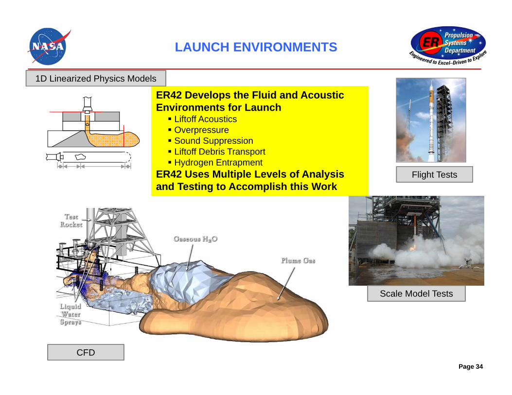
ER42 Develops the Fluid and Acoustic Environments for Launch Liftoff Acoustics Overpressure Sound Suppression Liftoff Debris Transport Hydrogen Entrapment
ER42 Uses Multiple Levels of Analysis and Testing to Accomplish this Work
ER42 Develops the Fluid and Acoustic Environments for Launch Liftoff Acoustics Overpressure Sound Suppression Liftoff Debris Transport Hydrogen Entrapment
ER42 Uses Multiple Levels of Analysis and Testing to Accomplish this Work
1D Linearized Physics Models
CFD
Flight Tests
Scale Model Tests

OVERPRESSURE – ANALYTICAL MODEL
p(t)
p+
0
(–) (–)
(+) (+)
tt1 t3
t2 t4
11
0
2 12
0
1 13
0
1 2 14
0
2
2
2 2
Ltc
L L Lt
cL L L
tc
L L L L Lt
c
P(t) 0P0 me
C0e0 2Akm
FT
2Akf
IOP PropagationPlane D
OP
Pro
paga
tion Pl
ane
source
L1 L2 LL
Overpressure Predictions Using Analytical Models
• Broadwell &Tsu Model: Linearized 1-D physics-based model for overpressure in a ducted launcher
• 4-wave model: Acoustic modification to incorporate resonant conditions
• Attenuation Model: Empirically based on Shuttle data or other motor/ engine correlations
• Knockdown Factors for water suppression or pressure wave diffraction: Empirically-based or CFD simulation-based
• Margin: Technical agreement based on CFD simulations and unknown
• Improvement – Continually improve models based on CFD, Test data, and Flight data
Broadwell and Tsu Model Application
4-Wave Physics Model
Page 35

OVERPRESSURE – CFD
CFD has recently shown to represent overpressure very accurately without the inclusion of water Demonstrated ability to capture IOP and DOP waves at several locations for dry
testsProvides ability to address limitations of Analytical models Accounts for complex flow scenarios
and three-dimensional launch pad geometry
Provides parametric studies where unknowns currently exist
Ongoing improvements include modeling water suppression systems, multiphase solid booster effluent, and capture higher frequency spectral content
ASMATCFD Simulation
CFD simulations with (right) and without (left) liquid engine plumes
CFD simulations with (right) and without (left) liquid engine plumes
Page 36

OVERPRESSURE – CFD ANIMATION
Page 37
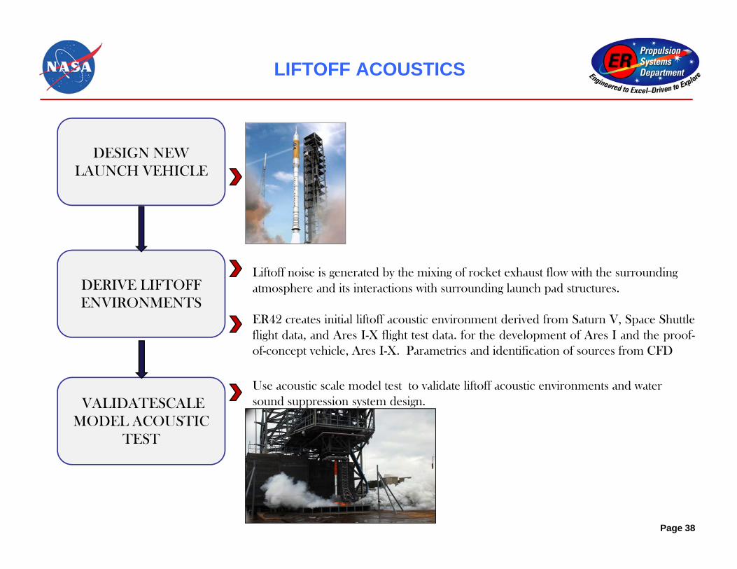
LIFTOFF ACOUSTICS
DESIGN NEW LAUNCH VEHICLE
VALIDATESCALE MODEL ACOUSTIC
TEST
DERIVE LIFTOFFENVIRONMENTS
Liftoff noise is generated by the mixing of rocket exhaust flow with the surrounding atmosphere and its interactions with surrounding launch pad structures.
ER42 creates initial liftoff acoustic environment derived from Saturn V, Space Shuttleflight data, and Ares I-X flight test data. for the development of Ares I and the proof-of-concept vehicle, Ares I-X. Parametrics and identification of sources from CFD
Use acoustic scale model test to validate liftoff acoustic environments and water sound suppression system design.
Page 38

SCALE MODEL ACOUSTIC TESTING
2
22
1
11
Vdf
VdfSt
• Determine model scale using Strouhal Number
• Design test article to this scale; fire; acquire data.
• Data Processing
Typical pressure time history with analysis window (a) and analysis window overlaid on chamber pressuremeasurement and RMS OASPL time history (b) and a one third octave plot for the test data compared to thescaled data (c).
(a) (b) (c)

SCALE MODEL TEST MOVIE

ASMAT VALIDATION OF CFD(COMPARISONS OF FREQUENCY WITHIN DUCT)
• Simulations of 5% scale rocket to model transient startup of motor
• Validated pressure temporal/spectral accuracy of CFD vs test data.
• Simulations showed good correlation with test data.– Matched pressure content above deck to 1000-1500 Hz– Matched pressure content below deck to 2000-3000 Hz
• Provided rationale and confidence to use CFD to predict environments for full-scale vehicles (up to ~ 150 Hz)
41

Solution: Implement hybrid approach of CFD + Computational Aero Acoustics (CAA) for liftoff acoustic fields• Use high-fidelity CFD modeling to
capture important plume physics (multi-phase plume, plume mixing and impingement, gas-water phase effects from deluge, etc.)
• Capture acoustic sources originating from plumes, impingement, capture water suppression effects
• Propagate using CAA from acoustic source surfaces enclosing noise source regions
APPROACH TO ACOUSTICS PROPAGATION CHALLENGE
Which CAA method is best suited for this application?• CAA acoustic field propagation method must be able to resolve
reflections, refraction and attenuation from interaction with structures such as launch platform and tower
• Two approaches under evaluation:• Boundary Element Method (BEM)• Farfield high-order Euler solution

• Major challenge arises in defining envelope of source regions for handover from CFD to CAA
• Plume boundary shape is quite complex due to interaction with launch pad • Example: Visualization of Noise Source regions for ASMAT Plume Impingement
Iso-surface of Acoustic Source regions
43
CHALLENGE: IDENTIFICATION OF THE ACOUSTIC SOURCE REGIONS
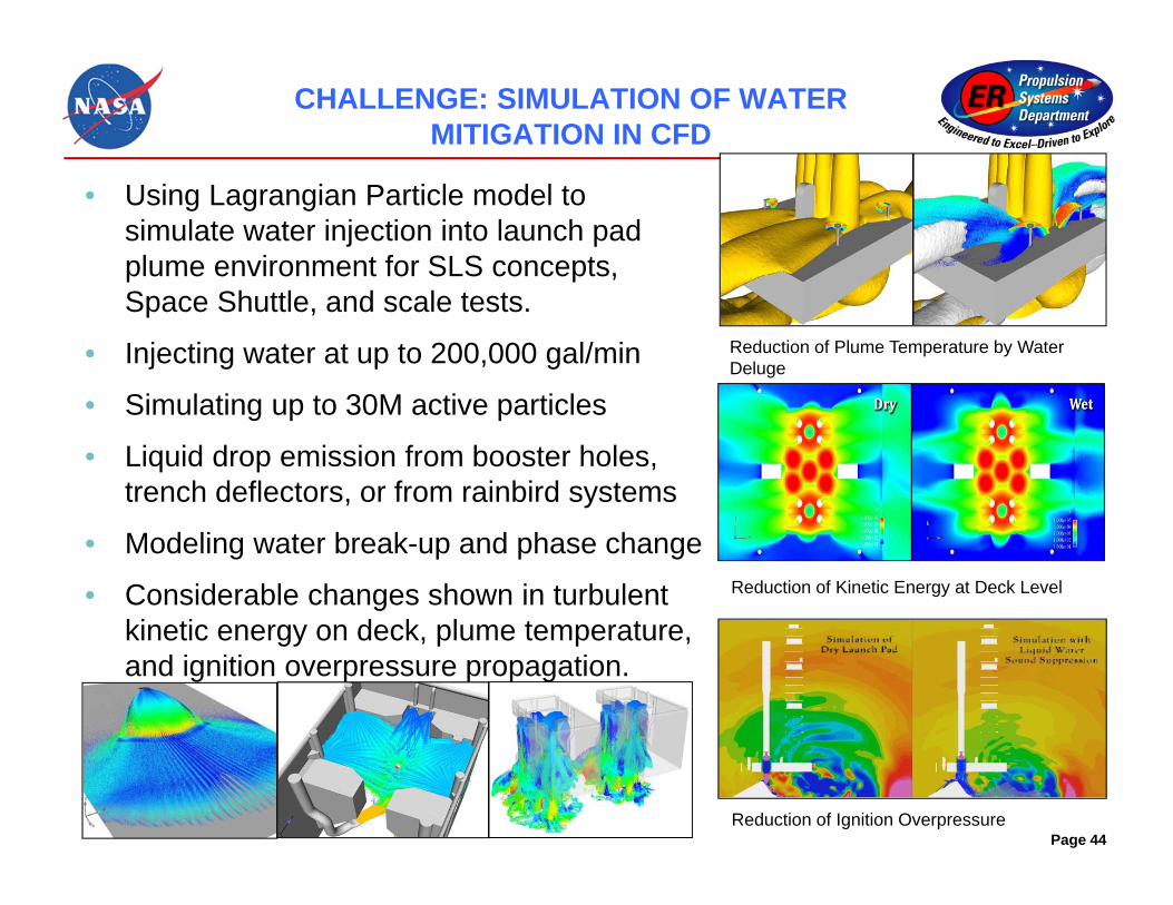
CHALLENGE: SIMULATION OF WATER MITIGATION IN CFD
• Using Lagrangian Particle model to simulate water injection into launch pad plume environment for SLS concepts, Space Shuttle, and scale tests.
• Injecting water at up to 200,000 gal/min
• Simulating up to 30M active particles
• Liquid drop emission from booster holes, trench deflectors, or from rainbird systems
• Modeling water break-up and phase change
• Considerable changes shown in turbulent kinetic energy on deck, plume temperature, and ignition overpressure propagation.
Reduction of Kinetic Energy at Deck Level
Reduction of Plume Temperature by Water Deluge
Reduction of Ignition OverpressurePage 44

SUMMARY
The Fluid Dynamics Branch at MSFC has the mission is to support NASA and other customers with discipline expertise to enable successful accomplishment of program/project goals
The branch is responsible for all aspects of the discipline of fluid dynamics, analysis and testing, applied to propulsion or propulsion-induced loads and environments, which includes the propellant delivery system, combustion devices, coupled systems, and launch and separation events
ER42 supports projects from design through development, and into anomaly and failure investigations
ER42 is committed to continually improving the state-of-its-practice to provide accurate, effective, and timely fluid dynamics assessments and in extending the state-of-the-art of the discipline
Page 45