MCR-87-578 EP 2 - NASA · MCR-87-578 EP 2.1 Space Station Integrated Propulsion and Fluid System...
99
MCR-87-578 EP 2.1 Space Station Integrated Propulsion and Fluid System Study Fluid Systems Configuration Databook Contract No. NAS8-36438 July 9, 1987 L. Rose B. Bicknell D. Bergman s. Wilson 7. Fester Program Manager Prepared for NASA Marshall Space Flight Center Alabama 35812 Martin Marietta Denver Aerospace P. 0 . Box 179 Denver, Colorado 80201 PROPULSION AND FLUID SYSTEM STUDY: FLUID SYSTEHS CONFIGURATION DATABOOK [gartin Narietta Aerospace) 99 p Avail: NTIS HC Unclas (NASA-CR-179215) SPRCE STATION INTEGB &TED ma- I 1753 A05/NF A01 CSCL 21H G3/2br 0709768 https://ntrs.nasa.gov/search.jsp?R=19880002371 2018-08-02T09:37:44+00:00Z
Transcript of MCR-87-578 EP 2 - NASA · MCR-87-578 EP 2.1 Space Station Integrated Propulsion and Fluid System...

MCR-87-578 EP 2.1
Space Station Integrated Propulsion and Fluid System Study
Fluid Systems Configuration Databook
Contract No. NAS8-36438
July 9, 1987
L. Rose B. Bicknell D. Bergman s. Wilson
7. Fester Program Manager
Prepared for
NASA Marshall Space Fl ight Center
Alabama 35812
Martin Marietta Denver Aerospace P . 0 . Box 179
Denver, Colorado 80201
PROPULSION AND FLUID SYSTEM STUDY: FLUID SYSTEHS C O N F I G U R A T I O N DATABOOK [gar t in Narietta Aerospace) 99 p A v a i l : N T I S HC Unclas
(NASA-CR-179215) SPRCE STATION INTEGB &TED m a - I 1753
A05/NF A01 CSCL 21H G3/2br 0709768
https://ntrs.nasa.gov/search.jsp?R=19880002371 2018-08-02T09:37:44+00:00Z
Table of Contents
Table of Contents . . . . . . . . . . . . . . . . . . . . . . . . . . . . . i List of Illustrations . . . . . . . . . . . . . . . . . . . . . . . . . . . iii List of Tables . . . . . . . . . . . . . . . . . . . . . . . . . . . . . . iv List of Abbreviations and Acronyms . . . . . . . . . . . . . . . . . . . . v
Foreword . . . . . . . . . . . . . . . . . . . . . . . . . . . . . . . . . vii Introduction . . . . . . . . . . . . . . . . . . . . . . . . . . . . . . . 1
1.0 United States Laboratory Module . . . . . . . . . . . . . . . . . . . 2
1.1 United States Laboratory Overall Requirements . . . . . . . . . . 2 1.2 United States Laboratory Fluid Systems Requirements . . . . . . . 2 1.3 United States Laboratory Fluid Systems Descriptions . . . . . . . 2
and Configurations 1.4 United States Laboratory References . . . . . . . . . . . . . . . 24
2 . 0 Habitation Module and Airlocks . . . . . . . . . . . . . . . . . . . . 25
2.1 Habitation Module and Airlocks Overall Requirements . . . . . . . 25 2.2 Habitation Module and Airlocks Fluid Systems Requirements . . . . 25 2.3 Habitation Module and Airlocks Fluid Systems Descriptions . . . . 25
and Configurations 2.4 Habitation Module and Airlocks References . . . . . . . . . . . . 25
3.0 Logistics Elements . . . . . . . . . . . . . . . . . . . . . . . . . . 26
3.1 Logistics Elements Overall Requirements . . . . . . . . . . . . . 26 3.2 Logistics Elements Fluid Systems Requirements . . . . . . . . . . 27 3.3 Logistics Elements Fluid Systems Descriptions . . . . . . . . . . 27
3.4 Logistics Elements References . . . . . . . . . . . . . . . . . . 30 and Configurations
4.0 Japanese Experimental Module (JEM) . . . . . . . . . . . . . . . . . . 31 4.1 Japanese Experimental Module Overall Requirements . . . . . . . . 31 4.2 Japanese Experimental Module Fluid Systems Requirements . . . . . 31 4.3 Japanese Experimental Module Fluid Systems Descriptions . . . . . 34
and Configurations 4.4 Japanese Experimental Module References . . . . . . . . . . . . . 47
5.0 Columbus Module . . . . . . . . . . . . . . . . . . . . . . . . . . . 48
5.1 Columbus Module Overall Requirements . . . . . . . . . . . . . . 48 5.2 Columbus Module Fluid Systems Requirements . . . . . . . . . . . 48 5.3 Columbus Module Fluid Systems Descriptions . . . . . . . . . . . 48
5.4 Columbus Module References . . . . . . . . . . . . . . . . . . . 49 and Configurations
6.0 Integrated Waste Fluid System (IWFS) . . . . . . . . . . . . . . . . . 50 6.1 Integrated Waste Fluid System Overall Requirements . . . . . . . 50 6.2 Integrated Waste Fluid System Requirements . . . . . . . . . . . 50 6.3 Integrated Waste Fluid System Description and Configuration . . . 51 6.4 Integrated Waste Fluid System References . . . . . . . . . . . . 56
i

~
t
7.0 Integrated Water System . . . . . . . . . . . . . . . . . . . . . . . . . 58
7.1 7.2
7.4
Integrated Water System Overall Requirements . . . . . . . . . . . . 58 Integrated Water System Requirements . . . . . . . . . . . . . . . . 58
7.3 Integrated Water System Description and Configuration . . . . . . . 58 Integrated Water System References . . . . . . . . . . . . . . . . . 60
8.0 Integrated Nitrogen System (INS) . . . . . . . . . . . . . . . . . . . . 62
8.1 Integrated Nitrogen System Overall Requirements . . . . . . . . . . 62 8.2 Integrated Nitrogen System Requirements . . . . . . . . . . . . . . 62
8.4 Integrated Nitrogen System References . . . . . . . . . . . . . . . 66 8 . 3 Integrated Nitrogen System Description and Configuration . . . . . . 62
9.0 Environmental Control and Life Support System . . . . . . . . . . . . . . 71 9.1 Environmental Control and Life Support System Overall Requirements . 71 9.2 Environmental Control and Life Support System Fluid Subsystems . . . 7 1
9.3 Environmental Control and Life Support System Fluid Subsystems . . . 72
9.4 Environmental Control and Life Support System References . . . . . . 78
Requirements
Descriptions and Configurations
10.0 Thermal Control System . . . . . . . . . . . . . . . . . . . . . . . . . 79
10.1 Thermal Control System Overall Requirements . . . . . . . . . . . . 79 10.2 Thermal Control System Fluid System Requirements . . . . . . . . . . 79 10.3 Thermal Control System Fluid System Description . . . . . . . . . . 81 10.4 Thermal Control System References . . . . . . . . . . . . . . . . . 83
and Configuration
11.0 Attached Payloads . . . . . . . . . . . . . . . . . . . . . . . . . . . . 84
11.1 Attached Payloads Overall Requirements . . . . . . . . . . . . . . . 84 11.2 Attached Payloads Fluid Systems Requirements . . . . . . . . . . . . 84 11.3 Attached Payloads Fluid Systems Descriptions . . . . . . . . . . . . 85
11.4 Attached Payloads References . . . . . . . . . . . . . . . . . . . . 85 and Configurations
12.0 Fluid Service/Vehicle Accommodations . . . . . . . . . . . . . . . . . . 86 12.1 Fluid Servicer/Vehicle Accommodations Overall Requirements . . . . . 86 12.2 Fluid Servicer/Vehicle Accommodations Fluid Systems Requirements . . 86 12.3 Fluid Servicer/Vehicle Accommodations Fluid Systems Descriptions . . 86
12.4 Fluid Servicer/Vehicle Accommodations References . . . . . . . . . . 89 and Configurations
ii

LIST OF ILLUSTRATIONS
1.3-1 1.3-2 1.3-3 1.3-4 1.3-5 1.3-6 1.3-7 1.3-8 4.3-1 4.3-2 4.3-3 4.3-4 4.3-5 6.3-1 7.3-1 8.3-1 8.3-2 8.3-3 8.3-4 9 -3-1 10.3-1 12.5-1
Process Material Management System Overview . . . . . . . . . . . . . . 5 PMMS Water Supply Design Concept . . . . . . . . . . . . . . . . . . 15 USL Cryogenic Refrigeration System . . . . . . . . . . . . . . . . . 15 Overview of the Process Waste Handling System . . . . . . . . . . . . 16 Process Waste Handling System Design Concept . . . . . . . . . . . . 17 PMMS Water Supply and Recovery System . . . . . . . . . . . . . . . . 20 Experiment Vacuum Vent System Design Concept . . . . . . . . . . . . 22 JEM ECLSS Schematic . . . . . . . . . . . . . . . . . . . . . . . . . 36 Thermal Control System and Emergency Battery Vent . . . . . . . . . . 37 Experiment Gas Supply Schematic . . . . . . . . . . . . . . . . . . . 41 Vacuum and Gas Vent . . . . . . . . . . . . . . . . . . . . . . . . . 44 Experiment Water Supply and Waste Water Management . . . . . . . . . 47 Integrated Waste Fluid System . . . . . . . . . . . . . . . . . . . . 52 Schematic of the Integrated Water System . . . . . . . . . . . . . . 59 Integrated Nitrogen System Functional Diagram . . . . . . . . . . . . 63 Integrated Nitrogen System Resupply Subsystem Schematic . . . . . . . 67 Integrated Nitrogen System Storage Subsystem Schematic . . . . . . . 69 Integrated Nitrogen System Distribution Subsystem . . . . . . . . . . 70 Environmental Control and Life Support System (ECLSS) Schematic . . . 73 Superfluid Helium Tanker Fluid System Schematic . . . . . . . . . . . 90
General Design Concept for USL Storage and Distribution . . . . . . . 13
USL Thermal Control System . . . . . . . . . . . . . . . . . . . . . 82
iii
I
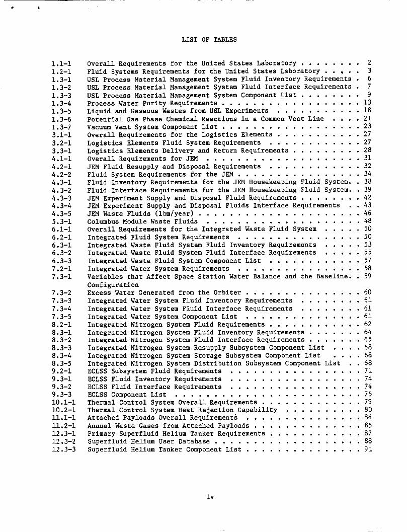
LIST OF TABLES
1.1-1 1.2-1 1.3-1 1.3-2 1.3-3 1.3-4 1.3-5 1.3-6 1.3-7 3.1-1 3.2-1 3.3-1 4 . 1.1 4.2-1 4.2-2 4.3-1 4.3-2 4.3-3 4.3-4 4.3-5 5.3-1 6.1-1 6.2-1 6.3-1 6.3-2 6.3-3 7.2-1 7.3-1
7.3-2 7.3-3 7.3-4 7.3-5 8.2-1 8.3-1 8.3-2 8.3-3 8.3-4 8.3-5 9.2-1 9.3-1 9.3-2 9.3-3 10.1-1 10.2-1 11.1-1 11.2-1 12.3-1 12.3-2 12.3-3
Overall Requirements for the United States Laboratory . . . . . . . Fluid Systems Requirements for the United States Laboratory . . . USL Process Material Management System Fluid Inventory Requirements USL Process Material Management System Fluid Interface Requirements USL Process Material Management System Component List Process Water Purity Requirements . . . . . . . . . . . . . . . . . Liquid and Gaseous Wastes from USL Experiments Potential Gas Phase Chemical Reactions in a Common Vent Line . . . Vacuum Vent System Component List Overall Requirements for the Logistics Elements . . . . . . . . . . Logistics Elements Fluid System Requirements Logistics Elements Delivery and Return Requirements Overall Requirements for JEM . . . . . . . . . . . . . . . . . . . JEM Fluid Resupply and Disposal Requirements Fluid System Requirements for the JEM . . . . . . . . . . . . . . .
. . . . . . . . . . . . . . . . .
. . . . . . . . . . . . . . . . . . . . . . . . . . . . . . . . . . . . . . . . . . . . . . .
Fluid Inventory Requirements for the JEM Housekeeping Fluid System . Fluid Interface Requirements for the JEM Housekeeping Fluid System . JEM Experiment Supply and Disposal Fluid Requirements . . . . . . . JEM Experiment Supply and Disposal Fluids Interface Requirements . JEM Waste Fluids (lbm/year) . . . . . . . . . . . . . . . . . . . . Columbus Module Waste Fluids . . . . . . . . . . . . . . . . . . . Overall Requirements for the Integrated Waste Fluid System . . . . Integrated Fluid System Requirements . . . . . . . . . . . . . . . Integrated Waste Fluid System Fluid Inventory Requirements . . . . Integrated Waste Fluid System Fluid Interface Requirements . . . . Integrated Waste Fluid System Component List . . . . . . . . . . . Variables that Affect Space Station Water Balance and the Baseline . Configuration Excess Water Generated from the Orbiter . . . . . . . . . . . . . . Integrated Water System Fluid Inventory Requirements . . . . . . . Integrated Water System Fluid Interface Requirements . . . . . . . Integrated Water System Component List . . . . . . . . . . . . . . Integrated Nitrogen System Fluid Requirements . . . . . . . . . . . Integrated Nitrogen System Fluid Inventory Requirements . . . . . . Integrated Nitrogen System Fluid Interface Requirements . . . . . . Integrated Nitrogen System Resupply Subsystem Component List . . . Integrated Nitrogen System Storage Subsystem Component List . . . Integrated Nitrogen System Distribution Subsystem Component List . ECLSS Subsystem Fluid Requirements . . . . . . . . . . . . . . . . ECLSS Fluid Inventory Requirements . . . . . . . . . . . . . . . . ECLSS Fluid Interface Requirements . . . . . . . . . . . . . . . . ECLSS Component List . . . . . . . . . . . . . . . . . . . . . . . Thermal Control System Overall Requirements . . . . . . . . . . . . Thermal Control System Heat Rejection Capability . . . . . . . . . Attached Payloads Overall Requirements . . . . . . . . . . . . . . Annual Waste Gases from Attached Payloads . . . . . . . . . . . . . Primary Superfluid Helium Tanker Requirements . . . . . . . . . . . Superfluid Helium User Database . . . . . . . . . . . . . . . . . . Superfluid Helium Tanker Component List . . . . . . . . . . . . . .
Integrated Water System Requirements . . . . . . . . . . . . . . .
. 2 . 3 . 6 . 7
. 9
. 1 3
. 1 8
. 2 1
. 2 3
. 2 7
. 2 7
. 2 8
. 3 1
. 3 2
. 3 4 . 38 . 39
. 4 2 . 43
. 4 6
. 4 8
. 5 0
. 5 0
. 5 3
. 5 5
. 5 7
. 5 8 . 59
. 6 0
. 6 1
. 6 1
. 6 1
. 6 2
. 6 4
. 6 5
. 6 8
. 6 8 . 68
. 7 1
. 7 4
. 7 4
. 7 5
. 7 9
. 8 0
. 8 4
. 8 5
. 8 7
. 8 8
. 9 1
iv

ABBREVIATIONS AND ACRONYMS
AFD AC S AC S AR B-CRS CFE ECLSS EEU ELM ESA EVA F FDS FMS GPF HFM HPTA HR&T IFMS IOC IOC INS IWFS IWS JEM KOH kW lb lbm LHe MEOP MLI MMU MORL MSFC NASA NASDA NHB NSTS OW ORU OSCRS OTV PLC PM PMMS PPV psia PWHS RF RMS
Aft Flight Deck Attitude Control System Atmosphere Control and Supply Atmosphere Revitalization Bosch Caron Reactor Subsystem Continuous Flow Electrophoresis Environmental Control and Life Support System Extra-vehicular Excursion Unit Experimental Logistics Module European Space Agency Extra-vehicular Activity Fahrenheit Fire Detection and Suppression Fluid Management System Gas Processing Facility Hollow Fiber Membrane High Pressure Tank Assembly Heat Rejection and Transport Integrated Fluid Management System Integrated Operational Capability Integrated Operations Configuration Integrated Nitrogen System Integrated Waste Fluid System Integrated Water System Japanese Experiment Module Potassium Hydroxide Kilowatt Pound Pounds Mass Liquid Helium Maximum Expected Operating Pressure Milti-Layer Insulation Manned Maneuvering Unit Manned Orbiting Research Laboratory (George C.) Marshall Space Flight Center National Aeronautics and Space Administration National Space Development Agency (Japanese) NASA Handbook National Space Transportation System Orbital Maneuvering Vehicle Orbit Replaceable Unit Orbital Spacecraft Consumable Resupply System Orbital Transfer Vehicle Pressurized Logistics Carrier Payload Module Process Material Management System Portable Pressure Vessels Pounds Per Square Inch Absolute Process Waste Handling System Radio Frequency Remote Manipulator System
. V
. I
SFHe S FHT SIRTF SMR ss s SP SSPE TBD TBS TC S TED THC ULC u SL U.S. WHS WM
ABBREVIATIONS AND ACRONYMS (continued)
Superf luid Helium Superf luid Helium Tanker Space I n f r a r e d Telescope F a c i l i t y Sabat ie r Methanation Reactor Space S t a t i o n Space S t a t i o n Program Space S t a t i o n Program Element To B e Determined To B e Determined by Suppl ier Thermal Control System Thermoelectric Device Temperature and Humidity Control Unpressurized L o g i s t i c s Carrier United S t a t e s Laboratory United S t a t e s Waste Handling System Waste Management
v i
FOREWORD
This r epor t w a s prepared by Martin Marietta Space Systems Company, under Contract NAS8-36438 i n compliance with d a t a submi t t a l requirement 5-1-3 i n t h e Statement-of-Work. The c o n t r a c t is being administered by Marshall Space F l i g h t Center, Huntsv i l le , Alabama. Mr. John Cramer is t h e NASA Pro jec t Manager.
v i i
INTRODUCTION
This databook conta ins f l u i d system requirements and system d e s c r i p t i o n s f o r Space S t a t i o n Program Elements. and I n t e r n a t i o n a l modules, in tegra ted f l u i d systems, a t tached payloads, f l u i d s e r v i c e r s and vehic le accommodation f a c i l i t i e s . F lu id system requirements and system conf igura t ions were der ived from the DR-02, "Databooks from Work Package 1" and October 19896 Flu ids In tegra ted Panel Data. t h i s document was used t o generate EP 2.2, "Space S t a t i o n Program Fluid Inventory Databook. "
Program elements include the United S t a t e s
Data contained i n
The f l u i d system requirements and system d e s c r i p t i o n s of each Space S t a t i o n Program Elements are def ined i n the following sec t ions .
Sect ion 1.0 Sect ion 2.0 Sec t ion 3.0 Sec t ion 4.0 Sect ion 5.0 Sect ion 6.0 Sect ion 7.0 Sect ion 8.0 Sect ion 9.0 Sect ion 10.0 Sect ion 11.0 Sect ion 12.0
United S t a t e s Laboratory Habi ta t ion Module and Air locks Log i s t i c s Elements Japanese Experimental Module Columbus In tegra ted Waste Flu id System In tegra ted Water System In tegra ted Nitrogen System Environmental Control and L i f e Support System Thermal Control System Attached Payloads F lu id Services/Vehicle Accommodations
Each sec t ion inc ludes a d iscuss ion of the o v e r a l l system requirements, s p e c i f i c f l u i d systems requirements and system desc r ip t ions . The system desc r ip t ions conta in conf igura t ions , f l u i d inventory da t a and component l ists . I n add i t ion , a l ist of information sources a r e referenced a t the end of each sec t ion .
1

1.0 UNITED STATES LABORATORY MODULE
1.1 UNITED STATES LABORATORY OVERALL REQUIREMENTS
The USL w i l l be a mul t id i sc ip l ine f a c i l i t y f o r payload accommodation wi th in a pressur ized habi tab le volume. and development most s e n s i t i v e t o acce le ra t ion , research i n bas ic science requi r ing long du ra t ion of extremely low acce le ra t ion l e v e l s , l i f e sciences research r e l a t i n g t o b e n e f i t s of and adapt ion t o long dura t ion exposure t o extremely low a c c e l e r a t i o n levels and con t ro l and monitoring of user-attached pressurized modules and se l ec t ed ex te rna l a t tached payloads.
f o r payload opera t ions w i l l enhance materials processes and a l low f o r the advancement of knowledge and the development of process cont ro ls . The USL w i l l a l s o accommodate the scale-up t o p i l o t p l an t opera t ions and the opera t ion of pre-production and commercial f a c i l i t i e s i n space.
The o v e r a l l requirements f o r t he United S t a t e s Lab (USL) Module a r e presented i n Table 1.1-1.
It w i l l accommodate materials research
The microgravi ty requirement of
Table 1.1-1 Overa l l Requirements f o r t he United S t a t e s Laboratory
1) 2)
3) 4 ) Provide a vacuum vent system. 5)
Accommodate the performance of s e l ec t ed complements of experiments. Provide cool ing of 6 kW with se l ec t ed double-rack cool ing of 15 kW t o accommodate experiment compliments. Provide a process f l u i d s system.
Provide a waste management system.
1.2 UNITED STATES LABORATORY FLUID SYSTEMS REQUIREMENTS
Fluid requirements f o r t he Environmental Control and L i f e Science System, Thermal Control System, Process Mater ia l s Management System, and Vacuum Vent System a r e provided i n Table 1.2-1.
1. 3 UNITED STATES LABORATORY FLUID SYSTEMS DESCRIPTIONS AND CONFIGURATIONS
The USL f l u i d systems may be categorized i n t o fou r working groups; the Environmental Control and L i f e Support System (ECLSS), the Thermal Control System (TCS), the Process Materials Management System (PMMS) and the Vacuum Vent S ys tem.
1.3.1 Environmental Control and L i f e Support Systems (ECLSS)
The USL Environmental Control and L i fe Support System's primary func t ion w i l l be t o maintain a hab i t ab le environment i n which the crew members can perform labora tory experiments. A system desc r ip t ion , f l u i d q u a n t i t i e s and component lists of the ECLSS have been included i n Sec t ion 9 of t h i s repor t .
cool ing and a i r contamination cont ro l . include cabin hea t exchangers, av ionics hea t exchangers and a i r r e v i t a l i z a t i o n equipment. Manned systems i n t e r f a c e s w i l l include the commode, shower and hand washing systems.
The primary ECLSS user i n t e r f a c e s w i l l be i n the areas of av ion ic s a i r Thermal con t ro l i n t e r f a c e s w i l l
2
J -
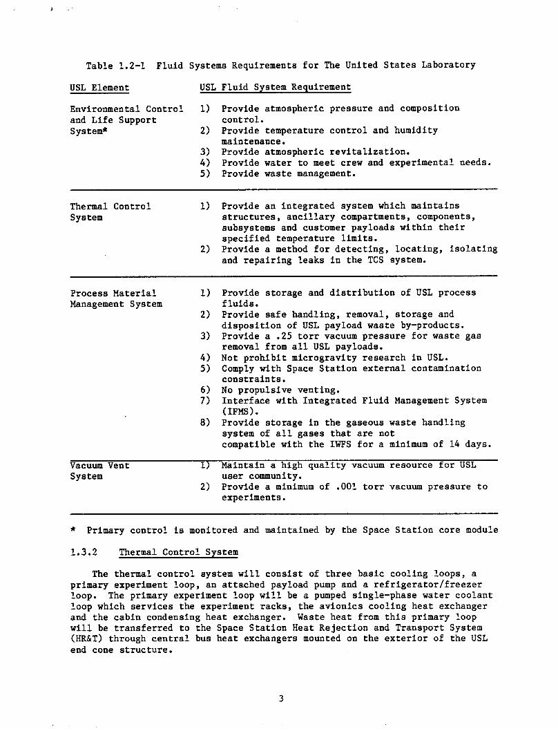
Table 1.2-1 Fluid Systems Requirements f o r The United S t a t e s Laboratory
USL Element USL Flu id System Requirement
Environmental Control 1) Provide atmospheric pressure and composition and Life Support con t ro l . System* 2) Provide temperature con t ro l and humidity
maintenance.
Provide water t o meet crew and experimental needs. 3) Provide atmospheric r e v i t a l i z a t i o n . 4) 5) Provide waste management.
Thermal Control 1) Provide an in t eg ra t ed system which maintains System s t r u c t u r e s , a n c i l l a r y compartments, components,
subsystems and customer payloads wi th in t h e i r spec i f i ed temperature l i m i t s .
and r epa i r ing leaks i n the TCS system. 2) Provide a method f o r de t ec t ing , l oca t ing , i s o l a t i n g
Process Material 1)
2) Management System
3)
4 ) 5 )
6 ) 7)
8)
Vacuum Vent 1) System
2)
Provide s torage and d i s t r i b u t i o n of USL process f l u i d s . Provide safe handling, removal, s to rage and d i s p o s i t i o n of USL payload waste by-products. Provide a .25 t o r r vacuum pressure f o r waste gas removal from a l l USL payloads. Not p roh ib i t microgravi ty research i n USL. Comply with Space S t a t i o n e x t e r n a l contamination cons t r a in t s . No propuls ive venting. I n t e r f a c e with In tegra ted Fluid Management System ( IFMS 1. Provide s torage i n the gaseous waste handling system of a l l gases t h a t are not compatible with the IWFS f o r a minimum of 14 days.
Maintain a high q u a l i t y vacuum resource for USL user community. Provide a minimum of .001 t o r r vacuum pressure t o experiments.
* Primary con t ro l is monitored and maintained by the Space S t a t i o n core module
1.3.2 Thermal Control System
The thermal con t ro l system w i l l c o n s i s t of t h ree bas ic cool ing loops, a primary experiment loop, an a t tached payload pump and a r e f r i g e r a t o r l f r e e z e r loop. loop which se rv ices the experiment racks, the av ion ic s cool ing hea t exchanger and the cabin condensing hea t exchanger. Waste hea t from t h i s primary loop w i l l be t r ans fe r r ed t o the Space S t a t i o n Heat Reject ion and Transport System (HR&T) through c e n t r a l bus hea t exchangers mounted on the e x t e r i o r of the USL end cone s t r u c t u r e .
The primary experiment loop w i l l be a pumped single-phase water coolant
3
The a t tached payload loop w i l l be used t o cool equipment i n ad jacent nodes. This loop w i l l a l s o use single-phase water as the working f l u i d .
Re f r ige ra t ion l f r eez ing s e r v i c e s w i l l be provided t o the USL with an in t eg ra t ed a i r f f r e o n cool ing loop. Heat acquired i n the f r e e z e r w i l l be t r ans fe r r ed t o low temperature body mounted r a d i a t o r s t o r e j e c t the hea t necessary t o meet a -3OOC f r e e z e r requirement.
resupply and as a r e s u l t will be considered independent from the in t eg ra t ed f l u i d systems. system purging t o remedy system contamination. However, the f l u i d q u a n t i t i e s spec i f i ed may be considered i n s i g n i f i c a n t i n comparison t o the o v e r a l l water inventory of the Space S t a t i o n elements.
The TCS w i l l be a closed loop system t h a t does not requi re scheduled f l u i d
Accommodations have been made i n the TCS f o r f l u i d leakage and
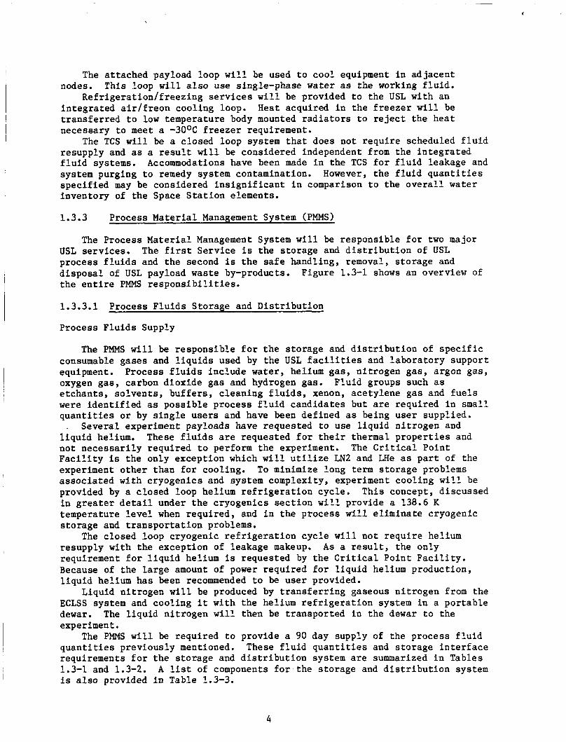
1.3.3 Process Material Management System (PMMS)
The Process Material Management System w i l l be respons ib le f o r two major USL serv ices . The f i r s t Serv ice i s the s torage and d i s t r i b u t i o n of USL process f l u i d s and the second is t h e s a f e handling, removal, s torage and d i sposa l of USL payload waste by-products. t h e e n t i r e PMMS r e s p o n s i b i l i t i e s .
Figure 1.3-1 shows an overview of
1.3.3.1 Process F lu ids Storage and Di s t r ibu t ion
Process F lu ids Supply
The PMMS w i l l be respons ib le f o r t he s torage and d i s t r i b u t i o n of s p e c i f i c consumable gases and l i q u i d s used by the USL fac i l i t i es and labora tory support equipment. Process f l u i d s include water, helium gas, n i t rogen gas , argon gas , oxygen gas , carbon dioxide gas and hydrogen gas. e tchants , so lvents , bu f fe r s , c leaning f l u i d s , xenon, acetylene gas and f u e l s were i d e n t i f i e d as poss ib l e process f l u i d candidates but a r e required i n small q u a n t i t i e s o r by s i n g l e use r s and have been def ined as being user suppl ied.
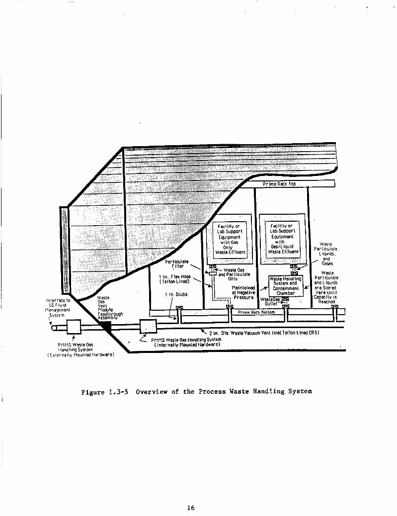
. Several experiment payloads have requested t o use l i qu id n i t rogen and l i q u i d helium. These f l u i d s a r e requested f o r t h e i r thermal p rope r t i e s and not necessa r i ly requi red t o perform the experiment. The Cri t ical Point F a c i l i t y is the only except ion which w i l l u t i l i z e LN2 and LHe as p a r t of the experiment o ther than f o r cooling. To minimize long term s torage problems assoc ia ted with cryogenics and system complexity, experiment cool ing w i l l be provided by a closed loop helium r e f r i g e r a t i o n cycle . i n g r e a t e r d e t a i l under the cryogenics s e c t i o n w i l l provide a 138.6 K temperature l e v e l when requi red , and i n the process w i l l e l imina te cryogenic s torage and t r anspor t a t ion problems.
resupply with the exception of leakage makeup. requirement f o r l i q u i d helium is requested by the Cri t ical Poin t F a c i l i t y . Because of the l a rge amount of power requi red f o r l i q u i d helium production, l i q u i d helium has been recommended t o be user provided.
Liquid n i t rogen w i l l be produced by t r a n s f e r r i n g gaseous n i t rogen from the ECLSS system and cool ing it with the helium r e f r i g e r a t i o n system i n a por tab le dewar. The l i q u i d n i t rogen w i l l then be t ranspor ted i n the dewar t o the experiment.
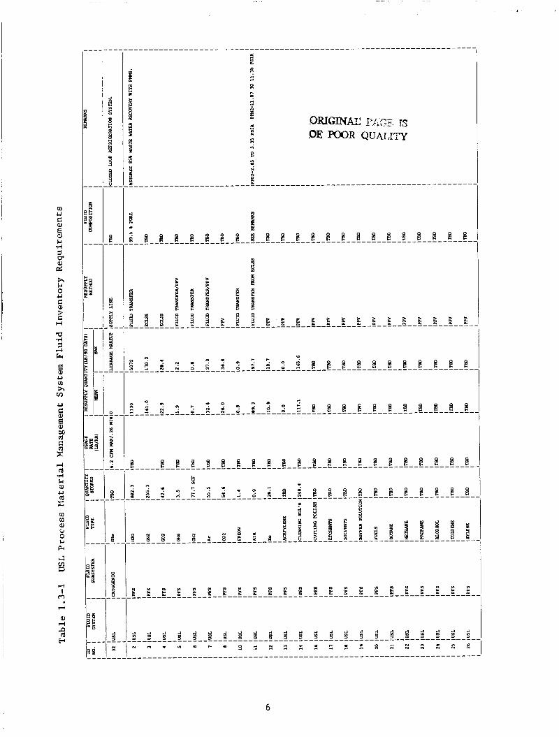
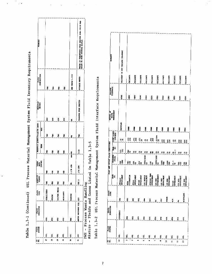
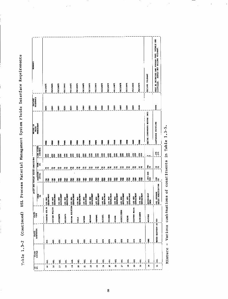
The PMMS w i l l be requi red t o provide a 90 day supply of the process f l u i d q u a n t i t i e s previously mentioned. These f l u i d q u a n t i t i e s and s torage i n t e r f a c e requirements f o r the s torage and d i s t r i b u t i o n system a r e summarized i n Tables 1.3-1 and 1.3-2. A l ist of components f o r the s torage and d i s t r i b u t i o n system i s a l s o provided i n Table 1.3-3.
F lu id groups such as
This concept, discussed
The closed loop cryogenic r e f r i g e r a t i o n cyc le w i l l not r e q u i r e helium A s a r e s u l t , the only
4
3 a, .rl ? M a, ? 0
'I
d I m d
a,
5
E
6
fn U
$4 ! d 1 FT aJ cr; h $4 0 U
!l
4
? G H
3 rl Fr
E a U (II h tn U
!l 5 3 bD a
z rl a d $4 aJ U a c fn aj aJ V 0 $4 PI I4 rn 3
n a Y
d U
u
rl I
m r(
aJ rl P (d k
2
v
.
" U
8
3
E aJ $4
*,-I
cll & 01 c) (d
W $4 aJ 2 t. H
U d 3 rl kl
U VI h rn U
$ I 8 M (d
z d m d 1.I aJ U a c ui In aJ V 0 U
-7 rn 3
hl I
m d
ai a d
a E..l
I
7
i l l I 2 I I 6 U VJ h VI
U
3 B 3 M Q
c rl (d ..-I . . u a, U Q r VI VI oi U 0 &I PI
2 3
h
d
W
hl I
m
8

8 8 8 8 8 8 8 8
9

u m
r PI
n a al
4 2
d ,
10 ORIGINAL PAGE IS m R QUALITY

u v1 1-I I 4
u ti Eo a U
8 a, u 0 h cn U
ti 8
9 a0 a
E: rl a .rl Ll a, u
v1 v1 a, 0 0 &I PI 4 v3 3
n -0 a, 7 C .rl u
U
m I
m rl
a, rl P a b
Eo W
11
Process F lu ids Storage
Process f l u i d s can be separated i n t o three separa te s torage ca tegor ies ; 1) USL dedicated PMMS s torage , 2) Space S t a t i o n in tegra ted f l u i d s s torage and user unique s torage. helium, argon, carbon dioxide gases and some water. Potable water w i l l be obtained through excess potable water genera t ion from the ECLSS and Orb i t e r f u e l cells. A separa te dedicated s torage f a c i l i t y w i l l be located i n the labora tory t o provide f o r t h e necessary water accumulation.
In tegra ted f l u i d s include excess oxygen and possibly excess hydrogen generated from the ECLSS which may be ava i l ab le f o r payload use. f l u i d s , a long with n i t rogen , t r a n s f e r r e d from the in tegra ted n i t rogen system, w i l l not r equ i r e dedicated s to rage i n the USL. User unique f l u i d s r e f e r t o the remainder of t h e f l u i d s requi red by USL payload equipment which a l s o do not r equ i r e dedicated s to rage and must be provided by the users.
of racks loca ted i n the USL f l o o r . Figure 1.3-2 shows the genera l design concept f o r the s torage and f l u i d d i s t r i b u t i o n of these f lu ids . gases w i l l be s to red under pressure i n two types of vessels . and small q u a n t i t i e s of helium and argon w i l l be s tored i n small por t ab le pressure ves se l s (PPV) a t 2000 psia . These v e s s e l s w i l l be approximately 14 inch by 6 inch cy l inde r s designed t o f i t both the f l u i d s torage rack and the f l u i d use r rack. The o the r gas s torage vesse l w i l l be a high opera t ing pressure vessel which feeds helium and argon i n t o a general ha rd l ine d i s t r i b u t i o n system t o the experiments. 30 inch by 9 inch cy l inde r s which operate up t o 3000 ps ia . suppl ied by the In t eg ra t ed Nitrogen System (INS) loca ted on t he s t a t i o n t r u s s s t ruc tu re .
Hydrogen gas is explosive i n na ture , t he re fo re l a r g e concent ra t ions of hydrogen gas q u a n t i t i e s should be avoided. w i l l be t r a n s f e r r e d t o the USL module and s tored i n tanks t h a t are approximately 33.7 f t 3 i n volume.
Oxygen w i l l a l s o be suppl ied from t h e ECLSS system. Present ly , t h i s is the only source necessary t o meet the 90 day resupply requirement.
Water may be suppl ied t o the dedicated s torage f a c i l i t y from the in t eg ra t ed water system which r ece ives excess water from seve ra l sources. These sources inc lude excess potable water generated from the ECLSS and the Orb i t e r f u e l cells . The dedicated water s torage tank will be capable of holding 992.3 lbm of water a t a s to rage pressure of 100 psia .
F lu ids which r equ i r e USL dedicated s torage include
These
Helium, Argon, carbon d ioxide , and water w i l l be s tored i n a combination
The three Carbon d ioxide ,
These vessels w i l l be approximately Nitrogen w i l l be
Providing hydrogen p resen t s several s a f e t y r e l a t e d design concerns.
Hydrogen suppl ied from the ECLSS
Process F lu id D i s t r i b u t i o n
The PMMS w i l l supply f l u i d s t o user equipment by two methods. Water,
Carbon dioxide and po r t ions of argon and helium ni t rogen, oxygen, argon and helium w i l l be t r ans fe r r ed d i r e c t l y from the s to rage f a c i l i t y t o the user. w i l l be suppl ied from por tab le pressure ves se l s (PPV), which can be plugged d i r e c t l y i n t o the user rack.
Processed Water Design Concept
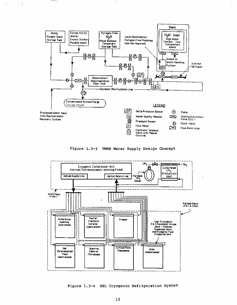
Water q u a l i t y requirements vary among d i f f e r e n t users . Twenty-six use r s requi re var ious water p u r i t i e s ranging from potable t o deionized and pyrogen-free water as shown i n Table 1.3-4. tank must be pu r i f i ed t o meet the needs of the deionized/pyrogen f r e e water users .
The potable water i n the s torage
12

- -
Figure 1.3-2 General Design Concept for USL Storage and D i s t r i b u t i o n
Table 1.3-4 Process Water P u r i t y Requirements
Equipment Name Potable D i s t i l l e d Deionized Pyrogen-free
Automated Cutt ing and Pol ishing X Analy t ica l Scale X X Acoustic L e v i t a t o r X Atmospheric Microphysics F a c i l i t y X Opt ica l Fiber Pul l ing TBD TBD TBD TBD High Temperature Furnace X X Auto Igni t ion X Droplet Spray Burning X Continuous Flow Elec t rophores i s X X Free F l o a t High Performance Liquid
Chromatograph TBD TBD I s o e l e c t r i c Focusing X X Organic and Polymer X X Membrane Production X Microwave Steam Autoclave TBD TBD P r o t e i n C r y s t a l Growth X X Solu t ion C r y s t a l Growth X Smal l Bridgeman E l e c t r o s t a t i c Levi ta tor EM L e v i t a t o r F loa t Zone Fluid Physics Premixed Gas Combustion Rotat ing Spherical Convection Sol id Surface Burning
TBD
X
TBD
TBD TBD
X
TBD
X X
TBD
X
TBD X X
TBD
X
p s i a )
ia)
13

Figure 1.3-3 shows the water supply design concept f o r the PMMS. water w i l l be mixed i n a common l i n e which f eeds the main deionized/ depyrogenation uni t . m u l t i f i l t r a t i o n u n i t s l inked i n series with an u l t r a f i l t r a t i o n device. The output water, which will meet a l l p u r i t y spec i f i ca t ions , w i l l then t r a n s f e r r e d t o the users through u t i l i t y runs i n 3 / 8 inch tubing.
Potable
The main u n i t which w i l l be a combination of
Cryogenics
The cryogenic f a c i l i t y shown i n Figure 1.3-4 w i l l be a closed loop helium system designed t o provide cool ing t o the experiments. comprise the r e f r i g e r a t i o n system inc ludes a compressor package, a cold head and a d i s t r i b u t i o n l i n e . The compressor package w i l l include a water cooled rec iproca t ing compressor, a h e a t exchanger, and the assoc ia ted e l e c t r i c a l con t ro l s . The cold head will be composed of one o r two s t age S t e r l i n g Cycle expansion device f o r LN2 genera t ion and the d i s t r i b u t i o n l i n e w i l l provide a means f o r the supply and r e t u r n of helium. r e f r i g e r a t i o n cyc le w i l l no t r equ i r e helium resupply with the except ion of makeup f o r helium leakage.
Crit ical Point F a c i l i t y . system and t r ans fe r r ed i n t o the cold head dewar. r e f r i g e r a t i o n system, the n i t rogen w i l l then be t r ans fe r r ed t o users .
The hardware t h a t w i l l
This closed loop cryogenic
A small quan t i ty of l i q u i d n i t rogen has been requested t o support the Gaseous n i t rogen w i l l be suppl ied from the ECLSS
Cooled by the helium
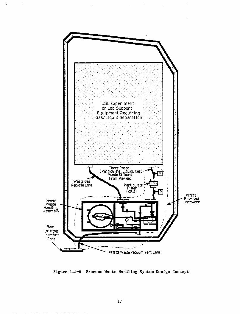
1.3.3.2 (PWHS) will be respons ib le f o r the safe removal, s torage and d i sposa l of USL
Process Waste Handling System - The Process Waste Handling System
payload waste by-products. 1.3-5. The source of waste will be from payload experiments, support equipment, and processes inc luding a laminar flow work bench, f l u i d s and p a r t i c u l a r glovebox, emergency shower, and eyewash. A component list of the PWHS is provided i n Table 1.3-3.
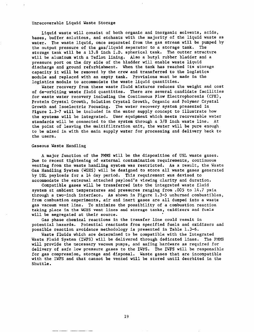
Figure 1.3-6 shows a layout of a t y p i c a l rack i n which th ree phase waste will be produced and the assoc ia ted hardware requi red t o provide the necessary waste management funct ions. handling assembly which w i l l be requi red i n a l l payloads r equ i r ing gas / l i qu id separat ion.
The waste handling assembly w i l l be a vacuum contained housing f o r the waste handling hardware. removing l i q u i d s from waste gases. When the l i q u i d has been removed, the waste gas is d ive r t ed t o t h e Waste Gas Handling System and the experiment is purged.
An overview of the (PWHS) is provided i n Figure
The assoc ia ted hardware w i l l make up the waste
The system provides a dynamic r e c i r c u l a t i o n loop f o r
Gas/Liquid Separat ion
Spacelab water sepa ra to r s , modified f o r cor ros ive condi t ions w i l l be used t o provide g a s l l i q u i d separat ion. t h ree times the l i q u i d pumping c a p a b i l i t y requi red i n the USL and are phys ica l ly l a r g e r than is des i r ed f o r t he USL. The predic ted e f f i c i e n c y of the sepa ra to r is approximately 99% which means t h a t approximately 1% of a l l the l i q u i d waste l i s t e d i n Table 1.3-5 w i l l be t r ans fe r r ed i n t o the waste gas handling system and poss ib ly i n the in t eg ra t ed waste management system. Liquid/gas sepa ra to r s w i l l be provided i n th ree f a c i l i t i e s , the l i f e sc ience glove box, t he c r y s t a l growth experiment and the ma te r i a l s glove box.
The sepa ra to r s are capable of providing
14
Potable Water Local Deionization/ Storage Tank Excess Orbller
Potable Waler
\ Storage Tank
High Waler Content Low
Contaminant
ou10u1'10 Wasle Handling System
Processed Water Input from Payload Water Recovery System
'- -9- -
CEGEND Della Pressure Sensor @) PumD
Water Quality monitor
Pressure Sensor
FIOW Meter
@ Electronic Solenoid Valve wilh Manual Ob'ei-ride
- L>(l Sealin Disconnect
Valve ?O D
0 Check Valve e Flow Restrictor
Figure 1 .3-3 PMMS Water Supply Design Concept
Cryogenic Compressor U n i t (He I lum Thermodvnam i c Work Ina F lu ld )
..I
Figure 1.3-4 USL Cryogenic Refr igerat ion System
15
Lab Support Equlpmeiil
Gas/llquid Waste
1 Iqulds, and ’ Gases i‘ ., >
Figure 1.3-5 Overview of the Process Waste Handling System
16
PMMS Was\e
Hand 1 ng Assembly
Rack Ut i 1 i ties I n terface
Panel
USL Experiment or Lab Support
Equipment Requiring Gas/L iquid Separat 1 on
Three Phase
Recycle Line (CRU) ;
PEMS /Provided
ciw 5war e
Figure 1.3-6 Process Waste Handling System Design Concept
17

ORGANICS
Table 1.3-5 Liquid and Gaseous Wastes from USL Experiments
LIQUIDS
To 1 ue ne Freon 22(Chlorodifluoromethane) Freon 113(Trichlorotrifluoroethane) Allyl Alcohol
Cyc lohexanol Isopropyl Alcohol Phenol Ac r o le in Trimethyl Benzene Indene Xylene Diisebutyl Ketone Methylethyl Ketone Furan Butyl Lactate Dichloromethane Trichloroethane Polyphenylene Sulfides TGS Solution (Triglycene Sulfate) Spent TGS Solution Gluderaldehyde
N-Butyl Alcohol
INORGANICS
Ammonia Latex Solution Water
SOLVENTS
Benzene Tr ic hloroe thy lene Ace to ne
MONATOMIC, DIATOMIC, AND LIGHT GASES
He Ar
co2 Xe co
02 N2 H2 H20
GASES
18
ETCHANTS (USED PRIMARILY IN THE GLOVEBOX)
Hydro-fluoric Acid [HFI Nitric Acid ("03) Acetic Acid [ (CH3CO) 201 Silver Nitrate [AgN03] Magnesium Iodide [MgI2] Hydrogen Peroxide [ H2021 Water [H20] Sodium Hydroxide [NaOH] Cupric Nitrate [Cu (NO31 21 Bromine [Br 21 Sod ium Hypoc hlor i t e [ NaOCl ] Potassium Hydroxide [KOH] Potassium Ferricyanide [K3Fe (CN] 6 Hydrochloric Acid [ HCl] Methanol [CH30H] Perchloric Acid
OTHER LIQUID WASTE SOLUTIONS
Buffer Solution Culture Medium Staining Solution Liquid Chromatography Carrier Ultra Pure Wash Water R a w Protein Solution Cleaning Solution Developer Fixer Biocide/Disinfectant Quench Solution Burn Catalytic and
Polishing Solution Monomer Solution
Suppressant Compounds
OTHER GASES
Light Hydrocarbons Halogens :
c12 F2
Freon 22 Freon 113 Organic Vapors Halon
Unrecoverable Liquid Waste Storage
Liquid waste will consist of both organic and inorganic solvents, acids, bases, buffer solutions, and etchants with the majority of the liquid waste as water. The waste liquid, once separated from the gas stream will be pumped by the output pressure of the gaslliquid separator to a storage tank. storage tank will be a 13.8 inch I.D. spherical tank. will be aluminum with a Teflon lining. pressure port on the dry side of the bladder will enable waste liquid discharge and ground refurbishment. capacity it will be removed by the crew and transferred to the logistics module and replaced with an empty tank. logistics module to accommodate the waste liquid quantities.
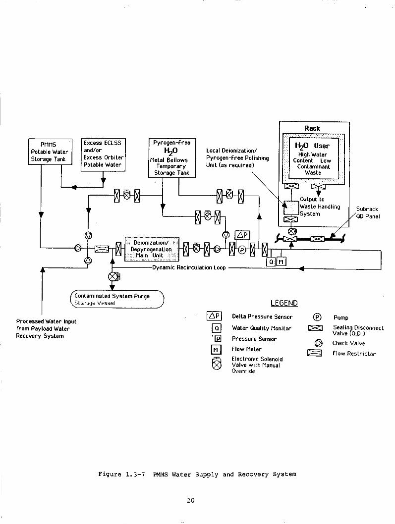
of de-orbiting waste fluid quantities. for waste water recovery including the Continuous Flow Electrophoresis (CFE), Protein Crystal Growth, Solution Crystal Growth, Organic and Polymer Crystal Growth and Isoelectric Focusing. Figure 1.3-7 will be included in the water supply concept to illustrate how the systems will be integrated. standards will be connected to the system through a 318 inch waste line. At the point of leaving the multifiltration unit, the water will be pure enough to be mixed in with the main supply water for processing and delivery back to the users.
The The outter structure
ALSO a butyl rubber bladder and a
When the tank has reached its storage
Provisions must be made in the
Water recovery from these waste fluid mixtures reduces the weight and cost There are several candidate facilities
The water recovery system presented in
User equipment which meets recoverable water
Gaseous Waste Handling
A major function of the PMMS will be the disposition of USL waste gases. Due to recent tightening of external contamination requirements, continuous venting from the waste handling system was restricted. As a result, the Waste Gas Handling System (WGHS) will be designed to store all waste gases generated by USL payloads for a 14 day period. This requirement was devised to accommodate the external attached payload's viewing clarity and duration.
system at ambient temperatures and pressures ranging from .005 to 14.7 psia through a two-inch interface. from combustion experiments, air and inert gases are all dumped into a waste gas vacuum vent line. taking place in the WGHS vent lines and storage tanks, oxidizers and fuels will be segregated at their source.
Gas phase chemical reactions in the transfer line could result in potential hazards. Potential reactants from specified fuels and oxidizers and possible reaction avoidance methodology is presented in Table 1.3-6.
Waste Fluid System (IWFS) will be delivered through dedicated lines. will provide the necessary vacuum pumps, and safing hardware as required for delivery of safe low pressure gases to the ITJFS. for gas compression, storage and disposal. Waste gases that are incompatible with the IWFS and that cannot be vented will be stored until deorbited in the Shuttle.
Compatible gases will be transferred into the integrated waste fluid
As shown in Figure 1.3-5 unburned combustibles,
To minimize the possibility of a combustion reaction
Waste fluids which are determined to be compatible with the Integrated The PMMS
The IWFS will be responsible
19
I Rack
Local Deionization/
Unit (as required)
Subr ack /aO Panel
Dynamic Recirculation Loop
Processed Water Input
Recovery System l from Payload Water
UGEND
Delta Pressure Sensor @ Pump
Water Quality Monitor
Pressure Sensor
Flow Meter
Electronic Solenoid Valve with Manual Override
Sealin Disconnect Valve ?Q.D.,
Check Valve
Flow Restrictor
Figure 1.3-7 PMMS Water Supply and Recovery System
2.0
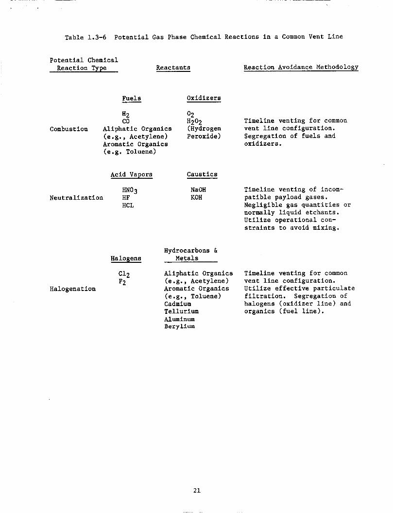
Table 1.3-6 Potential Gas Phase Chemical Reactions in a Common Vent Line
Potential Chemical Reaction Type Reactants Reaction Avoidance Methodology
Fuels Oxidizers - Timeline venting for common vent line configuration.
(e.g., Acetylene) Peroxide) Segregation of fuels and Aromatic Organics oxidizers. (e.g. Toluene)
H2 02 co H202
Combustion Aliphatic Organics (Hydrogen
Acid Vapors
"03 Neutralization HF
HCL
Caustics
NaOH KOH
Timeline venting of incom- patible payload gases. Negligible gas quantities or normally liquid etchants. Utilize operational con- straints to avoid mixing.
Hydrocarbons & Halogens Metals
Aliphatic Organics (e.g., Acetylene) vent line configuration. Aromatic Organics Utilize effective particulate (e.g., Toluene) filtration. Segregation of Cadmium halogens (oxidizer line) and Tellurium organics (fuel line). Aluminum Berylium
Timeline venting for common c12 F2
Halogenation
21
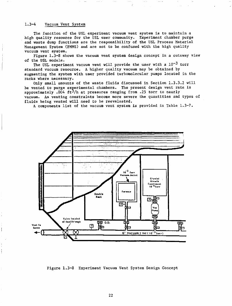
1.3-4 Vacuum Vent System
The func t ion of t h e USL experiment vacuum vent system is t o maintain a high q u a l i t y resource f o r t h e USL user community. Experiment chamber purge and waste dump funct ions are the r e s p o n s i b i l i t y of t he USL Process Material Management System (PMMS) and are not t o be confused wi th t h e high q u a l i t y vacuum vent system.
of t h e USL module.
standard vacuum resource. augmenting t h e system with use r provided turbomolecular pumps loca ted i n the racks where necessary.
Only small amounts of t h e waste f l u i d s discussed i n Sec t ion 1.3.3.2 w i l l be vented t o purge ex e r imenta l chambers.
vacuum. f l u i d s being vented w i l l need t o be reevaluated.
A components l ist of t he vacuum vent system is provided i n Table 1.3-7.
Figure 1.3-8 shows t h e vacuum vent system design concept i n a cutaway view
The USL experiment vacuum vent w i l l provide the user with a t o r r A higher q u a l i t y vacuum may be obtained by
The present design vent rate i s approximately .004 f t s /h a t p res su res ranging from .25 t o r r t o near ly
As vent ing c o n s t r a i n t s become more severe t h e q u a n t i t i e s and types of
Figure 1.3-8 Experiment Vacuum Vent System Design Concept
22

U VI .!-I A U
8 g 2
I 0 U
U VI h VI
U
8
?,
3
(d 3
I- I
m d
a rl P (d
E+
N Y N Y Y
23
1.4 UNITED STATES LABOMTORY REFERENCES
1) Peterson, T., Space S t a t i o n F lu id Inventor ies of the In tegra ted Waste Fluid and In t eg ra t ed Water Systems, PIR No. 191. NASA L e w i s Research Center, Cleveland, OH, March 1987.
2) Space S t a t i o n Def in i t i on and Preliminary Design, UP-01, Book 3 US Lab Module, SSP-MMC-00031, Rev. B, NAS8-36525. Martin Marietta Denver Aerospace, Denver, CO, O c t . 31, 1986.
3) F lu ids Technical I n t e g r a t i o n Panel Data, Presented a t Marshall Spacef l igh t Center, Huntsv i l le , AL, October 1986.
24
2.0 HABITATION MODULE AND AIRLOCKS
2.1 HABITATION MODULE AND AIRLOCKS OVERALL REQUIREMENTS
The Habi ta t ion Module w i l l be a common module o u t f i t t e d f o r use as the The a i r l o c k s w i l l be nodes which Space S t a t i o n (SS) crew l i v i n g quar te rs .
a l low f o r Extra-vehicular Ac t iv i ty (EVA) operat ions.
2.2 HABITATION MODULE AND AIRLOCKS FLUID SYSTEMS REQUIREMENTS
The cu r ren t I O C f o r SS calls f o r use of two a i r l o c k s , one access a i r l o c k and one hyperbaric a i r lock . a i r back i n t o the Space S t a t i o n before vent ing the remainder of the a i r t o space. work package and has no f l u i d requirements of i t s own. has the same requirements as the access a i r l o c k and a d d i t i o n a l l y must be capable of maintaining s t r u c t u r a l i n t e g r i t y up t o s i x atmospheres f o r r ep res su r i za t ion of personnel in jured due t o a damaged Extra-vehicular Excursion Unit (EEU) during EVA operat ions. hyperbaric opera t ions and the safe-haven opera t ions are both covered i n the ECLSS sect ion. A s such, t he Habi ta t ion Module and Air locks have no unique f l u i d system requirements which a r e not covered by the In tegra ted Systems. For d e t a i l e d f l u i d requirements r e f e r t o the appropr ia te s e c t i o n i n the system write-ups as follows:
The access a i r l o c k must pump up t o 90% of the usable
The pumping system t h a t does t h i s is considered p a r t of the s t r u c t u r e s The hyperbaric a i r l o c k
The f l u i d system requirements f o r
Sec t ion 6.0 Sec t ion 7.0 Sec t ion 8.0 Sec t ion 9.0 Sec t ion 10.0 Thermal Control System (TCS)
In t eg ra t ed Waste Flu id System (IWFS) In tegra ted Water System (IWS) In t eg ra t ed Nitrogen System (INS) Environmental Control and L i f e Support System (ECLSS)
2.3 HABITATION MODULE AND AIRLOCKS FLUID SYSTEMS DESCRIPTIONS AND CONFIGURATIONS
Fluid system d e s c r i p t i o n s and conf igura t ions f o r t h e Habi ta t ion Module, access a i r l o c k and hyperbaric a i r l o c k have been included i n the following sec t ions :
Sec t ion 6.0 Sec t ion 7.0 In tegra ted Water System Sec t ion 8.0 In tegra ted Nitrogen System Sec t ion 9.0 Environmental Control and L i f e Support System Sec t ion 10.0 Thermal Control System
In tegra ted Waste Fluid System
2.4 HABITATION MODULE AND AIRLOCKS REFERENCES
1) Space S t a t i o n Def in i t i on and Prel iminary Design, WP-01, Book 2 , SSP-MMC-00031, Rev. B, NAS8-36525. Martin Marietta Denver Aerospace, Denver, CO, October 31, 1986.
2) Space S t a t i o n Def in i t i on and Prel iminary Design, WP-01, Book 10 Air locks, SSP-MMC-00031, Rev. B, NAS8-36525. Martin Mar ie t ta Denver Aerospace, Denver, CO, October 31, 1986.
25
3 .O LOGISTICS ELEMENTS
L o g i s t i c s elements w i l l be used f o r t r anspor t ing t h e needed equipment, f l u i d s , and r a w materials t o support Space S t a t i o n crew and use r operations. The l o g i s t i c s elements w i l l a l s o serve t o t r anspor t experiment products and waste of a l l kinds back t o ea r th . Two types of l o g i s t i c s elements have been defined as Pressur ized L o g i s t i c s Carriers (PLC's) and Unpressurized Log i s t i c s Carriers (ULC's) f o r car ry ing d ry goods, f l u i d s , and p rope l l an t s . Both of t hese element types have been defined f o r t r anspor t ing s p e c i f i c ca t egor i e s of l o g i s t i c s resupply items.
are t o be used i n s i d e t h e pressur ized environment. i n t h e NSTS s h u t t l e cargo bay and w i l l be docked t o one of t he in te rconnec t ing nodes on the Space S ta t ion . PLC's payload from t h e o ther Space S t a t i o n modules.
The ULC's are a l s o launched i n t h e s h u t t l e , but they w i l l t r a n s p o r t goods and equipment t o the Space S t a t i o n f o r use ou t s ide the pressur ized environment. removed from t h e ULC and docked a t l o c a t i o n s ou t s ide t h e pressur ized environment. t r a n s f e r r e d t o Space S t a t i o n experiments o r subsystems loca ted ou t s ide the pressur ized modules.
The ULC's w i l l a l s o t r anspor t necessary f l u i d s t o the Space S t a t i o n and o the r f l u i d s u s e r s i n the Space S t a t i o n a r c h i t e c t u r e . t ranspor ted t o the Space S t a t i o n on f l u i d s p a l l e t s i n much the same way as t h e dry goods are t ranspor ted . umbi l ica ls t o t h e proper use r subsystem o r experiment. I n t h e event t h a t p rope l l an t s must be suppl ied t o use r s , a d d i t i o n a l f l u i d s pa l le t s w i l l be cons t ruc ted and designated as propel lan t pallets.
The PLC's w i l l t r a n s p o r t items f o r crew, s t a t i o n o r u se r resupply which The PLC w i l l be launched
This w i l l al low " s h i r t s leeve" access t o t h e
Dry goods w i l l be t ranspor ted on dry goods p a l l e t s , which can be
The goods are removed from t h e pa l le t as necessary and
The f l u i d s are
The f l u i d s p a l l e t s w i l l be connected with
3.1 LOGISTICS ELEMENTS OVERALL REQUIREMENTS
The l o g i s t i c s elements w i l l c o n s i s t of s e v e r a l independent cargo t r a n s p o r t veh ic l e s designed f o r use w i t h t he o the r Space S t a t i o n elements. provide a means f o r secur ing cargo wi th in the NSTS S h u t t l e and f o r s t o r i n g tne same cargo before and after use on the Space S t a t i o n s t r u c t u r e . Pressur ized L o g i s t i c s Carrier (PLC) w i l l provide a means f o r resupplying i n t e r n a l Space S t a t i o n crew and experiment supp l i e s without t h e use of a i r l o c k o r space su i t s .
The Unpressurized L o g i s t i c s Carriers (ULC's) w i l l a l low t r a n s p o r t of goods and materials t h a t w i l l be used ou t s ide the pressur ized environment o r f l u i d s t h a t w i l l be t r a n s f e r r e d t o i n t e r n a l systems through umbi l ica l connections. The use of t h e UPC's with no pressure s h e l l provides a means f o r c u t t i n g down t h e mass of s t r u c t u r e which must be launched i n t h e s h u t t l e .
The o v e r a l l requirements f o r t he Log i s t i c s Elements are presented i n Table 3.1-1.
They w i l l
The
26
3.2
Table 3.1-1 Overa l l Requirements f o r t he L o g i s t i c s Elements
The l o g i s t i c s elements must resupply consumables t o the Space S t a t i o n every 90 days.
The l o g i s t i c s elements s h a l l remain opera t iona l f o r a minimum of 10 years o r 40 f l i g h t s .
The l o g i s t i c s elements s h a l l provide a 50" by 50" hatch with 12" r ad ius corners t o accommodate t r a n s f e r of equipment between modules.
The weight of l o g i s t i c s elements s h a l l be kept t o a minimum.
The l o g i s t i c s elements shall provide a pressur ized volume.
The l o g i s t i c s elements s h a l l provide f a c i l i t i e s f o r s t o r i n g supp l i e s , spares , equipment an f l u i d s t o support Space S t a t i o n and users .
LOGISTICS ELEMENTS FLUID SYSTEMS REQUIREMENTS
Flu id system requirements f o r the l o g i s t i c s elements a r e presented i n Table 3.2-1.
Table 3.2-1 L o g i s t i c s Elements F lu id System Requirements
Element Requirements
Environmental Control 1) Provide temperature and humidity and L i f e Support System cont ro l . f o r PLC 2) Provide atmospheric con t ro l and supply.
3) Provide atmosphere r e v i t a l i z a t i o n . 4) Provide f i r e de tec t ion and suppression. 5) Provide resupply and r e t u r n of
consumables and o r b i t a l replacement u n i t elements f o r o the r func t ions wi th in the Space S t a t i o n Program.
3.3
Flu id Resupply Pallets 1) Provide c a p a b i l i t y t o unload, d i s t r i b u t e , and dispose of a l l f l u i d s necessary f o r Space S t a t i o n opera t ions , crew support , and user support .
f l u i d s w i l l be suppl ied by the Experimental Log i s t i c s Module.
2) Some Japanese Experimental Module
LOGISTICS ELEMENTS FLUID SYSTEMS DESCRIPTIONS AND CONFIGURATIONS
The desc r ip t ions and conf igura t ions of t he Log i s t i c s Elements vary g r e a t l y with the s i z e and number of experiments on Space S t a t i o n , t he s i z e of the crew, and the vent ing requirements imposed on d i sposa l systems. requirements imposed on the L o g i s t i c s Elements are d i r e c t l y r e l a t e d t o these configurat ions.
The f l u i d s
The d a t a presented i n Table 3.3-1 i s ex t rac ted from F lu ids
27
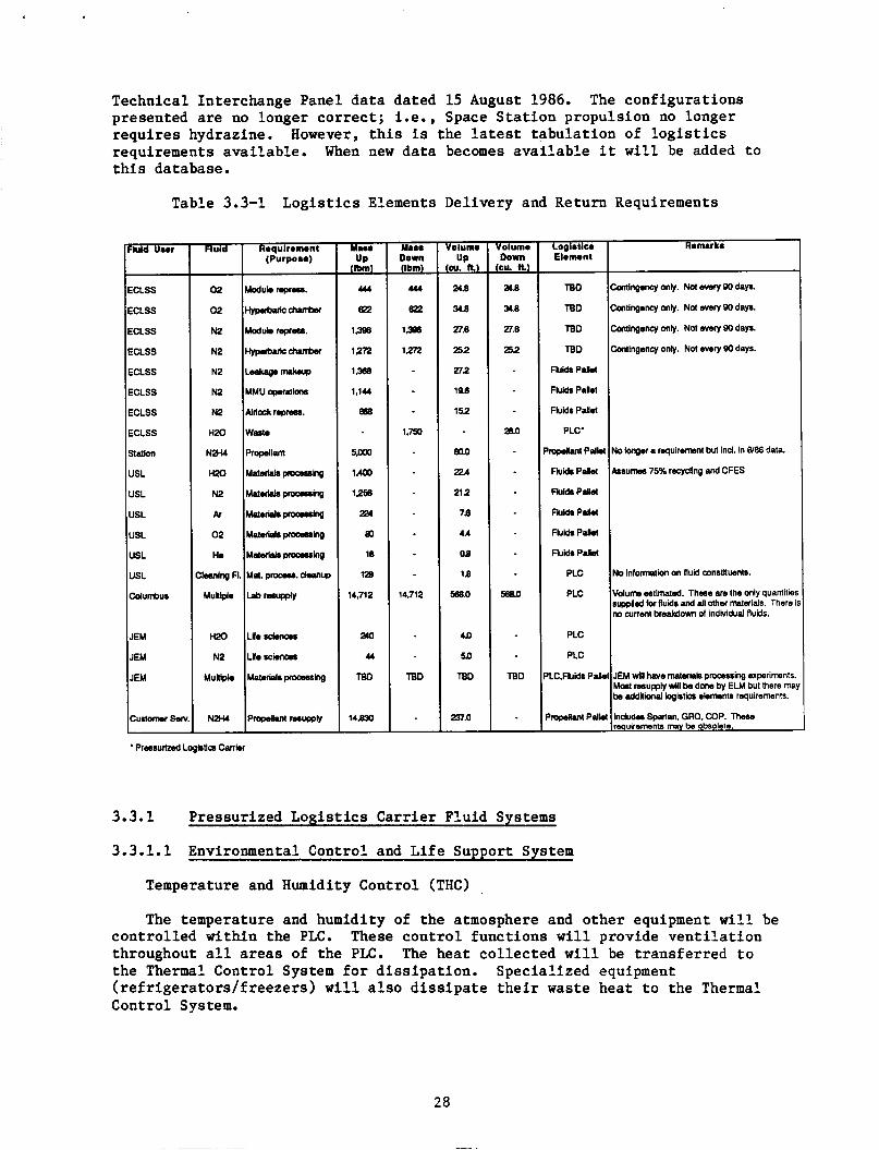
Technical Interchange Panel d a t a dated 15 August 1986. presented are no longer c o r r e c t ; i.e., Space S t a t i o n propuls ion no longer r equ i r e s hydrazine. However, t h i s is the l a tes t t abu la t ion of l o g i s t i c s requirements ava i l ab le . t h i s database.
The conf igura t ions
When new d a t a becomes a v a i l a b l e i t w i l l be added t o
Fluid
0 2
0 2
N2
N2
N2
N2
N2
HX)
N2H4
H20
N2
&
0 2
He
,lmning FL
Mullple
mo N2
MuWpk
N2H4
Table 3.3-1 L o g i s t i c s Elements Delivery and Return Requirements
Requiromenl (Purpose)
Modubmpfu.
uypubdcchanber
Modubrsprrr.
Hvprbulcchurkr
W m p k s u p
MMUqanfions
Aidcckroprau.
Waste
pmpdkm
Matuisk~wocming
M a l u i s k m h g
Maleridspcocaring
MaluiskLwocmha
Matuiakpmouhg
Mat. pcoau. ck.nup
Lsbrcumply
L L ~
Lifescionma
Materidspfocesshg
Prop.U.n(nrupply
h i d Uwr
ECLSS
ECLSS
ECLSS
ECLSS
ECLSS
ECLSS
ECLSS
ECLSS
Station
USL
USL
USL
USL
USL
USL
Columbus
JEM
JEM
JEM
Curtonw Ser
- Ma.. Down (Ibm)
444
622
1398
1,272
1.750
14,712
TBD
Volum. UP p. n)
24.8
348
27.6
252
272
19.6
152
mo
224
21 2
78
4*
08
18
58a.O
40
5a
TBD
237.0
Volume Down p. n i
a.6
36
27.6
252
a3.0
58a.O
TBD
Logietlc. Elomonl
TBD
TBD
TBD
TBD
Fluids P.8.1
Fluii Pdol
Fluids Pd.1
PLC'
mplun P d h
Fluids P.lat
Fluids Palid
Fluids PIy.1
FluidsPW
Fluids P . M
PLC
PLC
PLC
PLC
LC.FUi Pplk
' E p h I l t P d l
* Pressurized Lo@UQ Can!
3.3.1
3.3.1.1 Environmental Control and L i f e S u m o r t Svstem
Pressurized Log i s t i c s Carrier F lu id Systems
Temperature and Humidity Control (THC)
Remark.
htlngency only. Nd ovary 90 days.
XtWgency only. Not every 90 days.
htlngency only. Not every 90 days.
Mlngency only. Not ovary 90 days.
No longer a requirmnt but ind. in 8/86 data.
ksumm 75% recycling and CFES
No information on fluid wnstkwnts.
V d u m etimated. Thee are the only quantiUer supplied for fluids and dl &er maids . There i no current breakdown of indvidud fluids.
JEM will have mtef*h p-ing experiments. Mat resupply will be done by ELM but there ma be dditionai bgistiw ebments requirements.
Indude Sppnan. GRO. COP. These reauiraments m y be obsolete.
The temperature and humidity of the atmosphere and o the r equipment w i l l be con t ro l l ed wi th in the PLC. These c o n t r o l func t ions w i l l provide v e n t i l a t i o n throughout a l l areas of the PLC. The hea t co l l ec t ed w i l l be t r ans fe r r ed t o the Thermal Control System f o r d i s s ipa t ion . ( r e f r i g e r a t o r s / f r eeze r s ) w i l l a l s o d i s s i p a t e t h e i r waste hea t t o the Thermal Control System.
Spec ia l ized equipment

Atmosphere Control and Supply (ACS)
Atmosphere pressure and composition con t ro l func t ions w i l l provide f o r monitoring and r egu la t ing the p a r t i a l and t o t a l p ressure of oxygen and n i t rogen i n the PLC atmosphere. be provided along with the d i s t r i b u t i o n ' a n d s to rage of 02 and N2 f o r t he PLC, and the resupply of N2.
Vent and re l ief pressure func t ions w i l l also
Atmosphere R e v i t a l i z a t i o n (AR)
Monitoring of atmospheric c o n s t i t u e n t s and con t ro l of p a r t i c u l a t e s and b a c t e r i a w i l l be provided.
F i r e Detect ion and Suppression (FDS)
F i r e de t ec t ion and suppression equipment w i l l be provided f o r the pressur ized volume with both f i x e d and por tab le ex t inguishers and emergency por tab le breathing equipment as required.
Re supply/Re t u r n
Resupply consumables and emergency provis ions f o r t he e n t i r e Space
Replacement kits/ORU's f o r a l l ECLSS func t ions w i l l be included such as S t a t i o n Program ECLSS w i l l be provided. PLC. f i l ters , wipes, and water t reatment resupply. provided f o r waste water (b r ine ) , f e c a l material, t r a s h , and carbon f i l t e r s .
Tankage f o r H20 is loca ted i n the
Waste r e t u r n w i l l a l s o be
Addit ional information on t h e Space S t a t i o n ECLSS can be found i n Sec t ion 9.0 of t h i s document.
3.3.1.2 Laboratory Process F lu ids Rack
Resupply of process f l u i d s f o r the U.S. Laboratory (USL) w i l l c o n s i s t of f l u i d s racks c a r r i e d i n t e r n a l l y i n the Pressurized L o g i s t i c s Carrier. The racks may be t ranspor ted i n the Unpressurized Log i s t i c s Carrier (ULC) , but t h i s r equ i r e the use of an a i r l o c k t o have the rack ins ide . The requirements f o r process f l u i d s vary g r e a t l y with the number and type of experiments on board. As t he requirements are f u r t h e r developed, t he conf igura t ion of the labora tory process f l u i d s racks w i l l be b e t t e r def ined. The l abora to ry process f l u i d s conf igura t ion equipment l ist is TBD.
3.3.2 Unpressurized Log i s t i c s Carrier F lu id Systems
3.3.2.1. Flu ids Pa l le t - The f l u i d s p a l l e t w i l l be configured t o t r anspor t f l u i d s o the r than p rope l l an t s t o the Space S ta t ion . One f l u i d s p a l l e t conf igura t ion w i l l be used t o t r anspor t n i t rogen i n t o the s t a t i o n f o r resupply of the ECLSS system by means of the in t eg ra t ed n i t rogen d i s t r i b u t i o n system. The l o g i s t i c s of resupplying n i t rogen t o the space s t a t i o n program is discussed i n Sec t ion 8.0 of t h i s r epor t . A second conf igura t ion may be used t o resupply U.S. Laboratory (USL) process f l u i d s when the USL f l u i d s racks a r e t ransported i n the Unpressurized Log i s t i c s Carrier (ULC).
The resupply of p rope l l an t s w i l l be accomplished with the O r b i t a l Spacecraf t Consumable Resupply System as discussed i n Sect ion 12.0 of t h i s repor t .
29
3.4 LOGISTICS ELEMENTS REFERENCES
1) Fluids Technical Integrated Panel, presented a t Marshall Space Flight Center, Huntsville, AL, October, 1986.
2) Space Station Definit ion and Preliminary Design, UP-01, Book 4 - Logist ics Module. SSP-MMC-00031 (Rev. B). Martin Marietta Denver Aerospace, October, 1986. (Contract NAS8-26525).
30
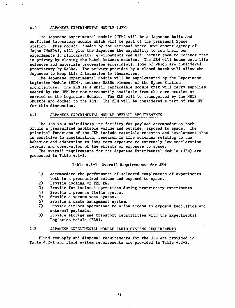
4.0 JAPANESE EXPERIMENTAL MODULE (JEM)
The Japanese Experimental Module (JEM) w i l l be a Japanese b u i l t and .
o u t f i t t e d labora tory module which w i l l be p a r t of the permanent Space S ta t ion . Japan (NASDA), w i l l g ive the Japanese the c a p a b i l i t y t o run t h e i r own experiments i n microgravi ty i n pr ivacy by c los ing the hatch between modules. sc iences and materials processing experiments, some of which are considered p ropr i e t a ry by NASDA. Japanese t o keep t h i s information t o themselves.
The Japanese Experimental Module w i l l be supplemented by the Experiment Log i s t i c s Module (ELM), another NASDA element of t he Space S t a t i o n a rch i t ec tu re . needed by the JEM but not necessa r i ly a v a i l a b l e from the core s t a t i o n or c a r r i e d on the L o g i s t i c s Module. Shu t t l e and docked t o the JEM. The ELM w i l l be considered a p a r t of the JEM f o r t h i s discussion.
This module, funded by the Nat ional Space Development Agency of
environments and w i l l permit them t o conduct them The JEM w i l l house both l i f e
The pr ivacy provided by a closed hatch w i l l a l low the
The ELM is a small rep laceable module t h a t w i l l c a r r y supp l i e s
The ELM w i l l be t ranspor ted by the NSTS
4.1 JAPANESE EXPERIMENTAL MODULE OVERALL REQUIREMENTS
The JEM is a mul t id i sc ip l ine f a c i l i t y for payload accommodation both wi th in a pressur ized hab i t ab le volume and outs ide , exposed t o space. p r i n c i p a l func t ions of the JEM include mater ia l s research and development t h a t is s e n s i t i v e t o acce le ra t ion , research i n l i f e sc iences r e l a t i n g t o the behavior and adapta t ion t o long term exposure t o extremely low acce le ra t ion levels, and observat ion of the e f f e c t s of exposure t o space.
The o v e r a l l requirements for the Japanese Experimental Module (JEM) a r e presented i n Table 4.1-1.
The
Table 4.1-1 Overal l Requirements for JEM
Accommodate the performance of se l ec t ed complements of experiments both i n a pressur ized volume and exposed t o space. Provide cool ing of TBD kW. Provide f o r i s o l a t e d opera t ions during p ropr i e t a ry experiments. Provide a process f l u i d s system. Provide a vacuum vent system. Provide a waste management system. Provide a i r l o c k opera t ions t o a l low access t o exposed f a c i l i t i e s e x t e r n a l payloads. Provide s torage and t r anspor t c a p a b i l i t i e s wi th the Experimental Log i s t i c s Module (ELM).
JAPANESE EXPERIMENTAL MODULE FLUID SYSTEMS REQUIREMENTS
and
Flu id resupply and d i sposa l requirements f o r t he JEM are provided i n Table 4.2-1 and f l u i d system requirements are provided i n Table 4.2-2.
31
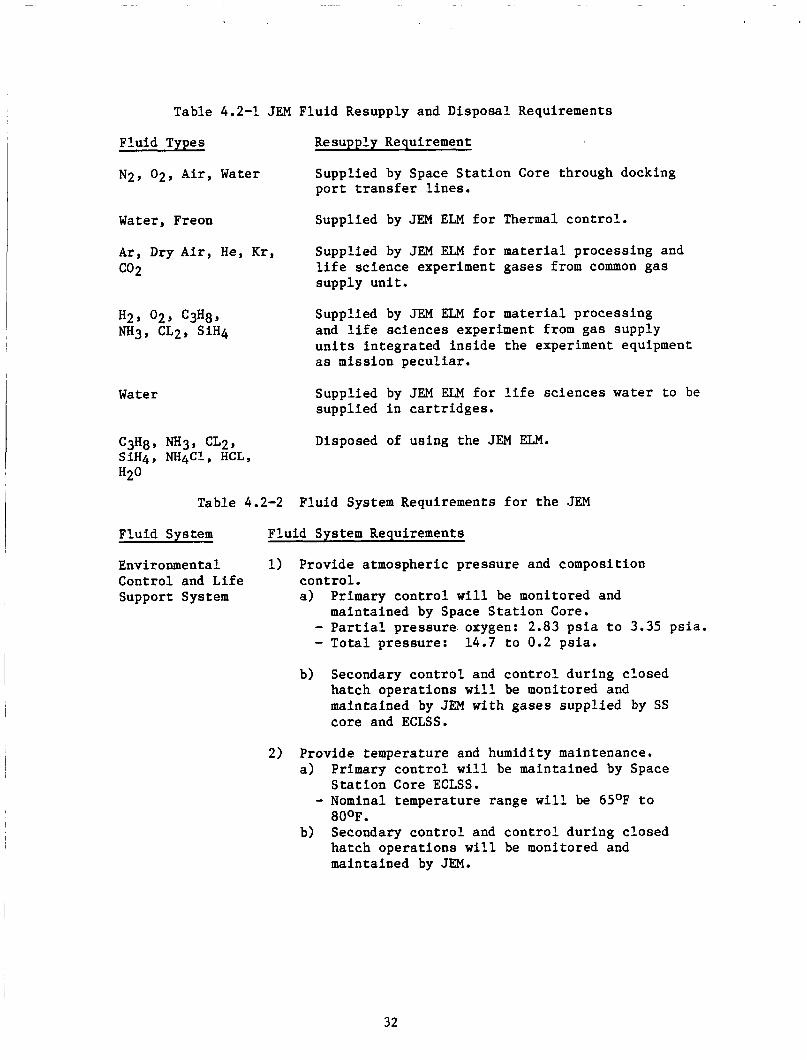
Table 4.2-1 JEM Fluid Resupply and Disposal Requirements
Fluid Types Resupply Requirement
N2, 02, Air, Water Supplied by Space Station Core through docking port transfer lines.
Water, Freon Supplied by JEM ELM for Thermal control.
Ar, Dry Air, He, Kr, Supplied by JEM ELM for material processing and life science experiment gases from common gas supply unit.
CO2
H2, 02, C3H8, "3, CL2, SiH4
Supplied by JEM ELM for material processing and life sciences experiment from gas supply units integrated inside the experiment equipment as mission peculiar.
Water Supplied by JEM ELM for life sciences water to be supplied in cartridges.
C3H8, "3, cL2, SiH4, NH4C1, HCL,
Disposed of using the JEM ELM.
H20
Table 4.2-2 Fluid System Requirements for the JEM
Fluid System Fluid System Requirements
Environmental 1) Provide atmospheric pressure and composition Control and Life control. Support System a) Primary control will be monitored and
maintained by Space Station Core. - Partial pressure oxygen: 2.83 psia to 3.35 psia. - Total pressure: 14.7 to 0.2 psia.
b) Secondary control and control during closed hatch operations will be monitored and maintained by JEM with gases supplied by SS core and ECLSS.
2) Provide temperature and humidity maintenance. a) Primary control will be maintained by Space
Station Core ECLSS.
80°F. Secondary control and control during closed hatch operations will be monitored and maintained by JEM.
- Nominal temperature range will be 65OF to b)
32

Table 4.2-2 F lu id System Requirements f o r the JEM (Continued)
Environmental 3) Provide atmospheric r e v i t a l i z a t i o n . Control and L i f e a) Primary r e v i t a l i z a t i o n d u t i e s w i l l be performed Support System by Space S t a t i o n core ECLSS. - Regenerate module atmosphere t o provide a
s a f e and hab i t ab le environment f o r the crew using intermodule v e n t i l a t i o n . - Primary source of oxygen is e l e c t r o l y s i s of recovered water. - Nitrogen supply provided by s torage and resupply. - Removal and processing of C02 w i l l be accomplished through a regenera t ive process.
b) Secondary r e v i t a l i z a t i o n and closed hatch r e v i t a l i z a t i o n . - Oxygen and n i t rogen w i l l be t r ans fe r r ed
from Space S t a t i o n with emergency s torage i n b o t t l e s . C02 w i l l be removed i n JEM and t r ans fe r r ed t o the Space S t a t i o n f o r reduction.
-
4) Provide water and waste management. a) Primary water supply and waste management i s
performed by Space S t a t i o n core ECLSS. - Col l ec t , process, and dispense potable and hygiene water t o meet crew and experimental needs. Ensure proper water q u a l i t y through pretreatment and pos t treatment. Trace gas analyzer l i n e provided.
dr inking water.
-
- Provide a closed-loop recovery system f o r
Secondary water supply and waste func t ions a r e performed by JEM ECLSS. - Potable and hygiene water from Space
S t a t i o n ECLSS are dispensed by JEM. - Eyewash and handwash water and condensate i s returned t o Space S t a t i o n waste water recovery.
b)
5 ) Provide thermal con t ro l f o r module and experiments. a ) Coolant water is recycled wi th in Thermal
Control System. b) Freon i s recycled wi th in Thermal Control System. Provide f i r e de t ec t ion and suppression. 6 )
33
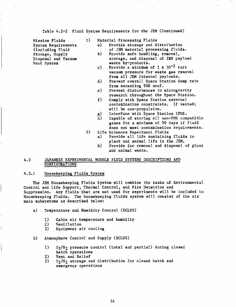
Table 4.2-2 F lu id System Requirements f o r the JEM (Continued)
Mission Flu ids 1 ) Mater ia l Processing F lu ids System Requirements a) Provide s torage and d i s t r i b u t i o n (Including Fluid Storage, Supply b) Provide safe handling, removal, Disposal and Vacuum Vent System waste by-products.
of JEM material processing f l u i d s .
s torage , and d i sposa l of JEM payload
Provide a minimum of 1 x low2 t o r r vacuum pressure f o r waste gas removal from a l l JEM i n t e r n a l payloads. Prevent o v e r a l l Space S t a t i o n dump r a t e from exceeding TBD sccf .
research throughout the Space S ta t ion . Comply with Space S t a t i o n ex te rna l contamination cons t r a in t s . I f vented; w i l l be non-propulsive.
g ) I n t e r f a c e with Space S t a t i o n IFMS. h ) Capable of s t o r i n g a l l non-FMS compatible
gases f o r a minimum of 90 days i f f l u i d does not meet contamination requirements.
c)
d )
e) Prevent d i s turbances t o microgravi ty
f )
2) L i f e Sciences Experiment F lu ids a) Provide a l l l i f e sus t a in ing f l u i d s t o
p l an t and animal l i f e i n the JEM. b) Provide f o r removal and disposal, of p l an t
and animal waste.
4.3 JAPANESE EXPERIMENTAL MODULE FLUID SYSTEMS DESCRIPTIONS AND CONFIGURATIONS
4.3.1 Housekeeping F lu ids System
The JEM Housekeeping F lu ids System w i l l combine the t a s k s of Environmental
Any f l u i d s t h a t a r e not used f o r experiments w i l l be included i n Control and L i f e Support, Thermal Control , and F i re Detect ion and Suppression. Housekeeping Fluids . main subsystems as descr ibed below:
The housekeeping f l u i d s system w i l l c o n s i s t of the s i x
Temperature and Humidity Control (ECLSS)
9 2) Vent i l a t ion 3) Equipment a i r cool ing
Cabin a i r temperature and humidity
Atmosphere Control and Supply (ECLSS)
l )
2) Vent and Rel ie f 3 )
02/N2 pressure con t ro l ( t o t a l and p a r t i a l ) during closed hatch opera t ions
02/N2 s torage and d i s t r i b u t i o n f o r c losed hatch and emergency opera t ions
34

c) Atmosphere Revitalization (ECLSS)
1) C02 removal 2) 3) 4) Contaminant control 5 ) Contaminant monitoring
C02 sent to Space Station ECLSS for reduction 02 supplied by electrolysis in Space Station core ECLSS
d) Water Recovery and Management (ECLSS)
1) 2) 3) Water distribution
Condensate water returned to Space Station ECLSS for processing Hygiene water returned to Space Station ECLSS for processing
- - hygiene water to hand washer potable water to eye wash
e) Fire Detection and Suppression
1) Fire detection 2) Fire suppression 3) Crew protection
f) Thermal Control
1)
2)
Cooling of experiments up to TBD kW, using water and freon cooling loops. Passive thermal control of JEM module by multilayer insulation (MLI) and thermal coatings.
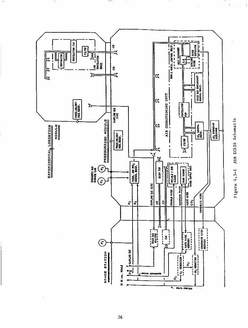
Figure 4.3-1 shows a schematic diagram of the Environmental Control and Life Support Subsystem of the JEM and its interfaces with the Space Station and ELM. the JEM. Housekeeping Fluids System.
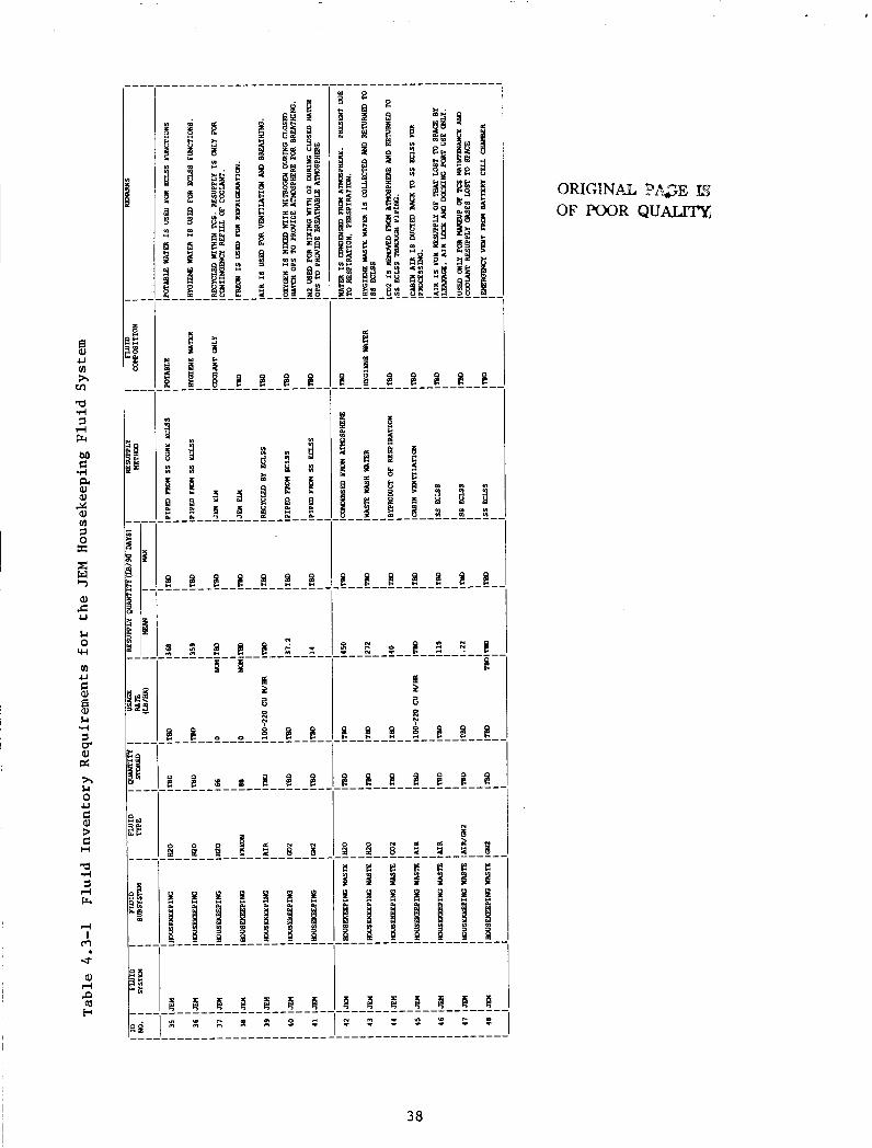
Figure 4.3-2 shows a schematic diagram of the Thermal Control System for Tables 4.3-1 and 4.3-2 provide fluids requirements for the
After use by the Housekeeping System, Housekeeping Fluids will either be returned to the Space Station ECLSS for reprocessing or, in the case of battery leakage fluids, (N2,02,H2) will be vented to space. The latter occurs only under emergency conditions.
35
.I 4
P 4
Y 3
D
::< I
U .I+ U
36

/ \ -- I I
F I i \
37
5 U VI h Cn -3 d 1 d r+ M C d a GI GI
cn 1 0 X
%
E r, GI c U
&I 0
W
VI U
5 5 &I .rl 1 cr. 9) d h Ll 0 U
fi ? C H
'd .rl 1 rl r+
d I
m
8 d P (d H
8 8 8 8 8 9 8
38

& B & & & & B 8 E
1 Fi
k? H i? I
8 8 8 % 6 % 8 8 88 8 8 88
I & e & 2 2 &e &I B B e e
39
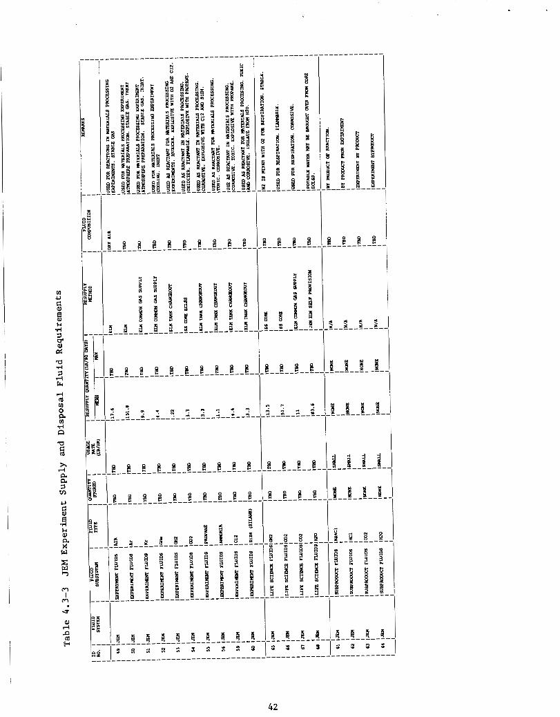
4 . 3 . 2 Mission F lu ids System
The JEM Mission F lu ids System combines the t a sks of Experiment Gas Supply, Gas and Vacuum Venting, and Experiment Water Supply and Waste Water Management. The following subsystems make up the Mission F lu ids System:
a ) Experiment Gas Supply
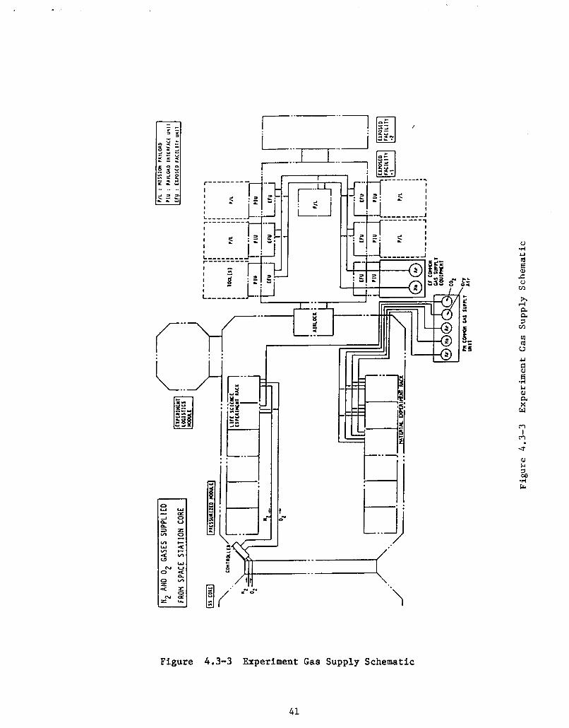
A schematic of the Experiment Gas Supply subsystem is shown i n Figure 4 . 3 - 3 , and i ts f l u i d s requirements a r e shown i n Tables 4.3-3 and 4 . 3 - 4 . Experiment Gas Supply subsystem w i l l provide process f l u i d s f o r the experiments which use common types of gas. t o the subsystem, one wi th in the pressurized module f o r supplying those experiments operated i n the s h i r t s l e e v e environment, and one t h a t w i l l provide f l u i d s t o the Exposed F a c i l i t y Uni t s ou ts ide the module.
The
There w i l l a c t u a l l y be two p ieces
The i n t e r n a l system w i l l supply krypton, helium, argon, and d ry a i r t o the ma te r i a l s experiment racks from a payload module (PM) common gas supply un i t . Carbon dioxide from the PM common gas supply u n i t w i l l be suppl ied t o the l i f e science experiment racks as w i l l be oxygen and n i t rogen gases from the Space S t a t i o n core.
The e x t e r n a l system w i l l supply helium and argon t o the exposed f a c i l i t y u n i t s ou t s ide the JEM f r o m separate exposed f a c i l i t y common gas supply equipment which w i l l be enclosed i n one of s eve ra l interchangeable payload modules.
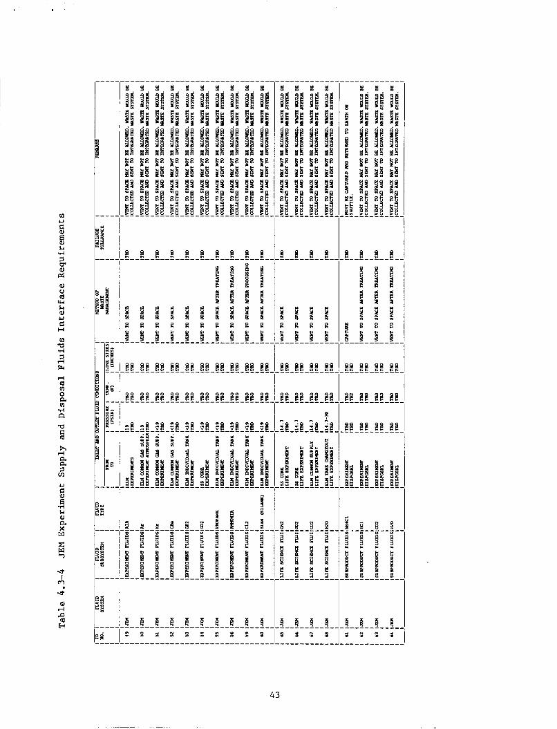
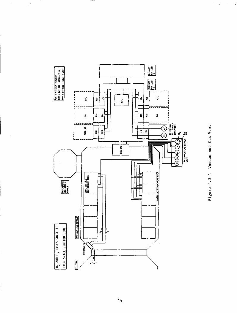
b) Gas and Vacuum Venting
The re ference conf igura t ion of the gas and vacuum vent systems i s shown i n Figure 4.3-4 as designed by the NASDA. This diagram shows the waste gas and vacuum vent systems being vented t o space. More recent s t u d i e s have shown a concern t h a t the c o n s t i t u e n t s of waste f l u i d s vented t o the surrounding environment may exceed column dens i ty or depos i t i on requirements. This concern c r e a t e s a need f o r e l imina t ing the waste f l u i d s by a method o the r than on demand vent ing. There a r e several a l t e r n a t i v e ways of e l imina t ing waste f l u i d s inc luding propuls ive ly vent ing through r e s i s t o j e t s on a continuous bas is , s t o r i n g the f l u i d s for 14 days and then vent ing them t o space a t one time, o r s t o r i n g them and r e tu rn ing them t o e a r t h on the NSTS Shu t t l e . Previous s t u d i e s i n d i c a t e that the most e f f e c t i v e method of d i sposa l i s t o combine the waste f l u i d s from a l l the Space S t a t i o n elements i n t o one in t eg ra t ed waste f l u i d s system (IWFS). dispose of a l l the f l u i d s using the chosen method. problems assoc ia ted wi th having seve ra l vent ing systems operated a t d i f f e r e n t times by d i f f e r e n t users .
This system would then be used t o This e l imina te s the
40
I I
2
a
r“ i..
! .----I . .
Y: h, /
h rl a a 3 VY
u a, a X W
Figure 4.3-3 Experiment Gas Supply Schematic
41
r i l l I I I
42
(II U
5 El
3 k .I4
c4 al c) a w & al U C H
(II a rl 5 rl ra d a m 0 a VI rl
'c1
n
2 h rl a a 1 VI
U
E d k al a X W
G c,
U I m U al rl P a w
! B i g s n P s
s
43
44
The Space S t a t i o n base l ine IWFS w i l l accept only s p e c i f i c gases f o r d i sposa l . each expected t o be discarded by the JEM. The f l u i d s t h a t cannot be disposed of by IWFS w i l l be s tored i n por tab le pressure ves se l s (PPVs) and returned t o e a r t h on the NSTS Shu t t l e . A compilation of a l l t he f l u i d s t o be disposed of by the JEM is shown i n Table 4 .3 -4 .
These gases a r e shown i n Table 4.3-5 along with the q u a n t i t i e s of
The vacuum vent system w i l l be is used f o r vent ing experiments a t pressures from .25 t o r r on down. f l u i d s from t h e experiments t h a t they w i l l be vented d i r e c t l y t o space. provides a ready source of vacuum down t o 1 x 10⁻³ t o r r . vacuum w i l l be obtained by augmenting the system with use r provided pumps loca ted in the racks where necessary.
It w i l l remove such a small quant i ty of This
Higher q u a l i t y
c ) Experiment Water Supply and Waste Water Management
The experiment Water Supply and Waste Water Management Experiment a r e shown i n Figure 4.3-5 . sc iences experiments i n the JEM. no water supply. included i n Table 4 .3 -2 . An opt iona l water supply l i n e i s shown i n Figure 4.3-4 . This would e l imina te some o r a l l of the need f o r experimental water supply from the ELM by using excess water from Space S t a t i o n ECLSS and o the r sources i n the core Space S ta t ion . This remains as merely an option. Disposal of experiment water af ter use i n the l i f e sc iences experiments w i l l be t o contaminant waste ca r t r idges . These PPVs w i l l be re turned t o e a r t h i n the ELM on the space s h u t t l e . There are no p lans t o process t h i s waste o r t o i n t e g r a t e i t with o the r Space S t a t i o n systems.
Experiment water w i l l be supplied only t o l i f e The materials experiments w i l l be required
The water requirement f o r t he l i f e sc iences experiments i s
45

Table 4.3-5 JEM Waste Fluids ( l b d y e a r )
Fluid 1995 1996 1997 1998 1999 2000 2001 2002 2003 2004
Argon
c02
C02/CH4
Freon
Helium
Hydrogen
I Nitrogen
Oxygen
Xenon
Krypton
608 608 608
0 0 0
0 0 0
0 0 0
18 18 18
1 1 1
54 54 54
30 30 30
0 0 0
40 40 40
608 608
0 0
0 0
0 0
18 18
1 1
54 54
30 30
0 0
40 40
608 608
0 0
0 0
0 0
18 18
1 1
54 54
30 30
0 0
40 40
608 608 608
0 0 0
0 0 0
0 0 0
18 18 18
1 1 1,
54 54 54
30 30 30
0 0 0
40 40 40
Totals : 751 751 751 751 751 751 751 751 751 751
46

.PRIMARILY WATER SUPPLIED BY J E M ' s L O G I S T I C S WATER TANKS (REFERENCE)
.WATER SUPPLY BRANCHED OFF JEM i ECLSS (OPTION)
EXPERIMENTAL L O C I S T I C S
MODULE
TANK STORAGE
SPACE STATION CORE PRESSURIZED MODULE
BATCH SUPPLY CONCEPT
WATER SUPPLY CARTRIDGE (PORTABLE T A N K )
Figure 4.3-5 Experiment Water Supply and Waste Water Management
4.4 JAPANESE EXPERIMENTAL MODULE REFERENCES
1) Fluids Technical Integration Panel, presented at Marshall Space Flight Center, Huntsville, AL, October, 1986.
2) Peterson, T., Space Station Fluid Inventories of the Integrated Waste Fluid and Integrated Water Systems, PIR No. 191. NASA Lewis Research Center, Cleveland, OH, March, 1987.
47
5.0 COLUMBUS MODULE
The Columbus module w i l l be a labora tory module o u t f i t t e d f o r both materials processing and l i f e sciences experiments. be b u i l t and funded by the European Space Agency (ESA) providing the Europeans the opportuni ty t o perform t h e i r own experiments without bui lding t h e i r own space s t a t i o n .
desc r ip t ions , and conf igura t ions of the Columbus module. However, M r . Hans D. Schmitz, i n t he European Space Agency, has of fe red h i s a s s i s t a n c e i n providing d a t a assoc ia ted with the Columbus Module. A s d a t a becomes ava i l ab le , it w i l l be added t o the database and used t o update the commonality study.
The Columbus module w i l l
A t p resent , almost no information is a v a i l a b l e about t he requirements,
5.1 COLUMBUS MODULE OVERALL REQUIREMENTS
The f ixed , o v e r a l l requirements f o r Columbus a r e unavailable. Requirements t h a t can be der ived f o r Columbus a r e presented i n Table 5.1-1.
Table 5.1-1 Columbus Derived Requirements
- Provide an environment which al lows crew members t o perform a se l ec t ed
- Provide a process f l u i d s system. - Provide a waste management system. - Provide a vacuum vent system.
group of experiments wi th in a " s h i r t sleeve" environment.
5.2 COLUMBUS MODULE FLUID SYSTEMS REQUIREMENTS
Columbus F lu ids Subsystem requirements are TBD.
5.3 COLUMBUS MODULE FLUID SYSTEMS DESCRIPTIONS AND CONFIGURATIONS
5.3.1 Environmental Control and L i f e Support (ECLSS)
The Columbus Module ECLSS conf igura t ion is TBD.
5.3.2. Process F lu ids Supply System
The Columbus Module Process Fluids Supply System configuration is TBD. The q u a n t i t i e s of f l u i d s t o be resuppl ied are a l s o unavai lable , but can be der ived f o r some f l u i d s based on waste q u a n t i t i e s e s t ab l i shed f o r the Japanese Experimental Module and the United S t a t e s Laboratory. These q u a n t i t i e s are shown i n Table 5.3-1.
5.3.3. Waste F lu ids System
The Columbus Module Waste F lu ids System conf igura t ion is TBD. q u a n t i t i e s of f l u i d s a v a i l a b l e f o r d i sposa l t o the Space S t a t i o n In tegra ted Waste F lu ids System a r e shown i n Table 5.3-1.
The
48
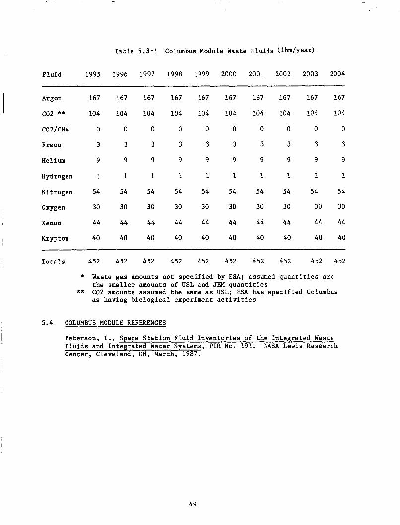
Table 5.3-1 Columbus Module Waste Flu ids (Ibm/year)
1995 1996 1997 1998 1999 2000 2001 2002 2003 2004 I I Fluid
Argon
c02 ** C02 /CH4
Freon
Helium
Hydrogen
Nitrogen
Oxygen
Xenon
Krypton I
167 167 167
104 104 104
0 0 0
3 3 3
9 9 9
1 1 1
54 54 54
30 30 30
44 44 44
40 40 40
167 167
104 104
0 0
3 3
9 9
1 1
54 54
30 30
44 44
40 40
167 167
104 104
0 0
3 3
9 9
1 1
54 54
30 30
44 44
40 40
167
104
0
3
9
1
54
30
44
40
167 167
104 104
0 0
3 3
9 9
A. 1 1
54 54
30 30
44 44
40 40
Tota ls 452 452 452 452 452 452 452 452 452 452
* Waste gas amounts not spec i f i ed by ESA; assumed q u a n t i t i e s a r e the smaller amounts of USL and JEM q u a n t i t i e s
as having b io log ica l experiment a c t i v i t i e s ** C02 amounts assumed the same as USL; ESA has spec i f i ed Columbus
5.4 COLUMBUS MODULE REFERENCES
Peterson. T.. SDace S t a t i o n Fluid Inven to r i e s of the In tegra ted Waste . - A - - - - .A
Flu ids and In t eg ra t ed Water Systems, P I R No. 191. NASA L e w i s Research Center, Cleveland, OH, March, 1987.
49

6.0
6.1
6.2
INTEGRATED WASTE F L U I D SYSTEM (IWFS)
INTEGRATED WASTE FLUID SYSTEM OVERALL REQUIREMENTS
The o v e r a l l requirements f o r t he IWFS a r e presented i n Table 6.1-1.
Table 6.1-1 Overal l Requirements f o r the In t eg ra t ed Waste Flu id System
1 ) Co l l ec t waste f l u i d s discarded by the s t a t i o n elements t h a t a r e compatible with s a f e c o l l e c t i o n and s torage.
2) Transfer , condi t ion and a l l o c a t e the co l l ec t ed f l u i d s f o r d i sposa l o r r e t u r n systems.
3) Control and monitor c o l l e c t i o n , t r a n s f e r , s torage , condi t ioning, a l l o c a t i o n and d i sposa l of waste f l u i d s .
4) W i l l not preclude the a b i l i t y of i nd iv idua l s t a t i o n elements t o provide a vacuum resource t o the use r i n t e r f a c e .
5 ) Waste f l u i d s t h a t cannot be accepted by the IWFS must be disposed of by the Space S t a t i o n Program Element (SSPE) o r system assoc ia ted with o r opera t ing from a SSPE, provided t h a t the requirements of waste handling and vent ing are met.
INTEGRATED WASTE FLUID SYSTEM REQUIREMENTS
In teg ra t ed f l u i d system requirements are presented i n Table 6.2-1.
Table 6.2-1 In tegra ted Fluid System Requirements
Parameter Requirements
Growth 1 )
2)
In tegra ted Design 1)
I n t e r f a c e Hardware 1)
Fluid Storage Requirements
1)
2)
I O C systems s h a l l have growth and on-orbit reconf igura t ion c a p a b i l i t y t o accommodate changing demands i n user f l u i d q u a n t i t i e s . System shall incorpora te sca r r ing t o accommodate a d d i t i o n a l i n t eg ra t ed system a t l o g i c a l f u l l opera t iona l capab i l i t y .
System s h a l l be in t eg ra t ed t o minimize f l u i d management hardware development and opera t iona l cos t .
Fluid i n t e r f a c e components shall be s tandar ized , and f l u i d t r a n s f e r i n t e r f a c e hardware s h a l l be designed t o preclude mating t o the wrong connector.
A f l u i d quan t i ty measurement c a p a b i l i t y s h a l l be provided i n both the s torage and resupply systems. Leakage de tec t ion , i s o l a t i o n , and con t ro l s h a l l be provided and shall comply with s t a t i o n environmental and contamination requirements.
50
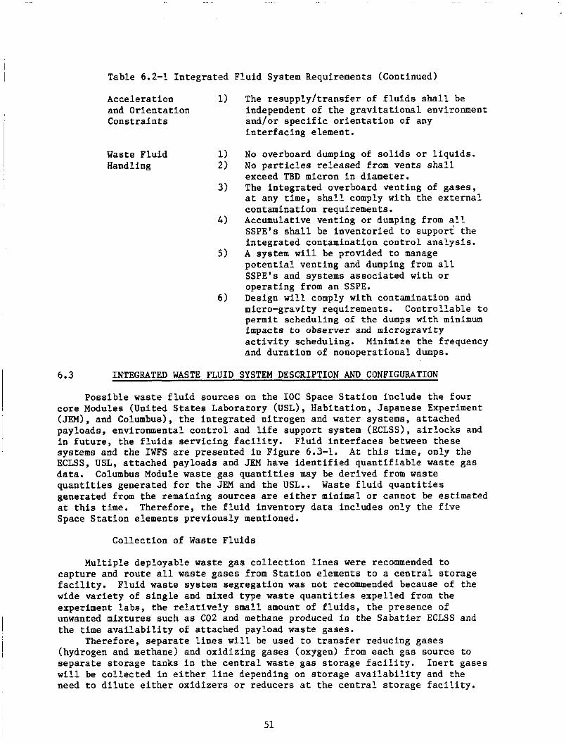
Table 6.2-1 In tegra ted Fluid System Requirements (Continued)
Accelerat ion 1) and Or ien ta t ion Cons t ra in ts
Waste Fluid 1) Handling 2)
The r e supp ly / t r ans fe r of f l u i d s s h a l l be independent of the g r a v i t a t i o n a l environment and/or s p e c i f i c o r i e n t a t i o n of any i n t e r f a c i n g element.
3)
4)
5 )
6 )
6.3 INTEGRATED WASTE FLUID SYSTEM DESCRIPTION AND CONFIGURATION
Poss ib le waste f l u i d sources on the I O C Space S t a t i o n include the four core Modules (United S t a t e s Laboratory (USL), Habi ta t ion , Japanese Experiment (JEM) , and Columbus) , t he in t eg ra t ed n i t rogen and water systems, a t tached payloads, environmental con t ro l and l i f e support system (ECLSS), a i r l o c k s and i n f u t u r e , t he f l u i d s se rv i c ing f a c i l i t y . Fluid i n t e r f a c e s between these systems and the IWFS are presented in Figure 6.3-1. ECLSS, USL, a t tached payloads and JEM have i d e n t i f i e d quan t i f i ab le waste gas
q u a n t i t i e s generated f o r t he JEM and the USL.. Waste f l u i d q u a n t i t i e s generated from the remaining sources are e i t h e r minimal o r cannot be est imated
Space S t a t i o n elements previously mentioned.
A t t h i s time, only the
~ data . Columbus Module waste gas q u a n t i t i e s may be der ived from waste
I a t t h i s time. Therefore, t he f l u i d inventory da t a includes only the f i v e I
Col lec t ion of Waste F lu ids
No overboard dumping of s o l i d s o r l i qu ids . No p a r t i c l e s re leased from vents s h a l l exceed TBD micron i n diameter. The in tegra ted overboard vent ing of gases , a t any time, s h a l l comply with the ex te rna l contamination requirements. Accumulative vent ing o r dumping from a l l SSPE's s h a l l be inventor ied t o support the in t eg ra t ed contamination con t ro l ana lys i s . A system w i l l be provided t o manage p o t e n t i a l vent ing and dumping from a l l SSPE's and systems assoc ia ted with o r operat ing from an SSPE. Design w i l l comply with contamination and micro-gravity requirements. Cont ro l lab le t o permit scheduling of the dumps w i t h minimum impacts t o observer and microgravi ty a c t i v i t y scheduling. Minimize the frequency and du ra t ion of nonoperational dumps.
Mult iple deployable waste gas c o l l e c t i o n l i n e s were recommended t o capture and route a l l waste gases from S t a t i o n elements t o a c e n t r a l s torage f a c i l i t y . F lu id waste system segregat ion was not recommended because of the wide v a r i e t y of s i n g l e and mixed type waste q u a n t i t i e s expel led from the experiment l abs , t he r e l a t i v e l y small amount of f l u i d s , t he presence of unwanted mixtures such as C02 and methane produced i n the Saba t i e r ECLSS and the time a v a i l a b i l i t y of a t tached payload waste gases.
(hydrogen and methane) and oxid iz ing gases (oxygen) from each gas source t o separa te s torage tanks i n the c e n t r a l waste gas s torage f a c i l i t y . I n e r t gases w i l l be co l l ec t ed i n e i t h e r l i n e depending on s torage a v a i l a b i l i t y and the need t o d i l u t e e i t h e r ox id i ze r s o r reducers a t the c e n t r a l s torage f a c i l i t y .
Therefore, s epa ra t e l i n e s w i l l be used t o t r a n s f e r reducing gases
51

I I .
I I I .
-B- Oirporrl
Figure 6.3-1 In tegra ted Waste Fluid System
Waste f l u i d c o l l e c t i o n w i l l opera te from 10 t o 15 ps i a . Two low pressure compressors w i l l be a c t i v a t e d when t h e c o l l e c t i o n system reaches 15 p s i a which t r a n s f e r s f l u i d s i n t o a 35 p s i a accumulator. F lu id system requirements f o r t h e IWFS c o l l e c t i o n system are presented i n Tables 6.3-1 and 6.3-2. The waste gases presented i n Tables 6.3-1 and 6.3-2 represent only those gases s u i t a b l e f o r IWFS s t o r a g e and r e s i s t o j e t propuls ion system use. Solvents , a c i d s , o i l s and brine-type f l u i d mixtures w i l l no t be allowed t o e n t e r t h e IWFS.
52
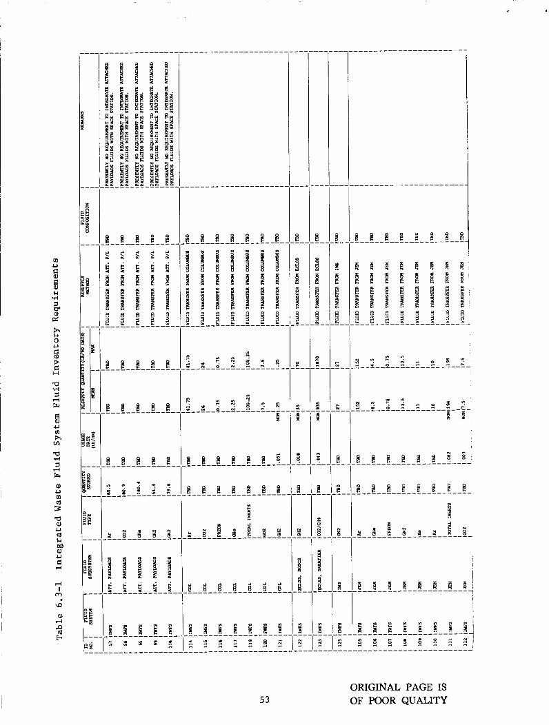
I 1 E
I
53
8 8 8 6 8 8 8 8
6 8 8 8 8 8 8 8

8 U VI h VI
a Q) U
U
H E:
n
a,
v
54

VI U
8 5 3 I-1 d
a,
a, 0 (d w I-1 a, U G H
a 94 7 d Fr
B
3
u VI h m
7 d Fr
al U VI cd 3 a a, u a Ld M a, 4J G H
CU I
m \o
a, rl P a w
Y I W C " " 0 4 4 -
h h b - ' o c o " N - 4 3
55
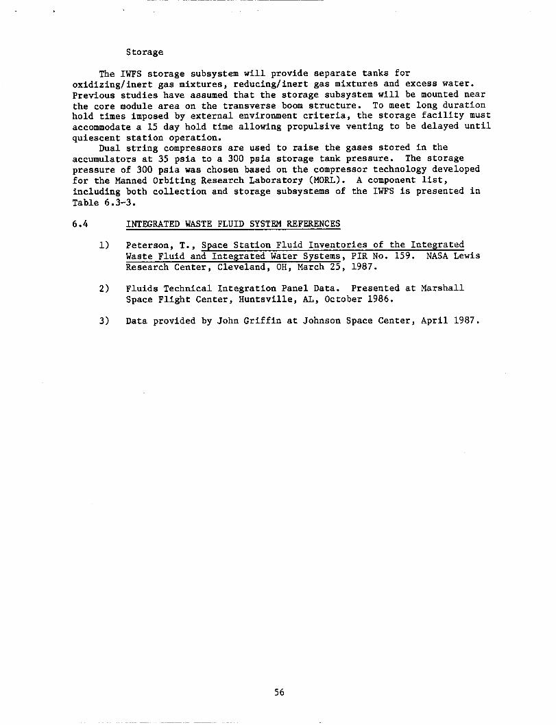
Storage
The IWFS storage subsystem will provide separate tanks for oxidizing/inert gas mixtures, reducing/inert gas mixtures and excess water. Previous studies have assumed that the storage subsystem will be mounted near the core module area on the transverse boom structure. To meet long duration hold times imposed by external environment criteria, the storage facility must accommodate a 15 day hold time allowing propulsive venting to be delayed until quiescent station operation.
Dual string compressors are used to raise the gases stored in the accumulators at 35 psia to a 300 psia storage tank pressure. pressure of 300 psia was chosen based on the compressor technology developed for the Manned Orbiting Research Laboratory (MORL). including both collection and storage subsystems of the IWFS is presented in Table 6.3-3.
The storage
A component list,
6.4 INTEGRATED WASTE FLUID SYSTEM REFERENCES
1) Peterson, T., Space Station Fluid Inventories of the Integrated Waste Fluid and Integrated Water Systems, PIR No. 159. NASA Lewis Research Center, Cleveland, OH, March 25, 1987.
2 ) Fluids Technical Integration Panel Data. Presented at Marshall Space Flight Center, Huntsville, AI,, October 1986.
3) Data provided by John Griffin at Johnson Space Center, April 1987.
56
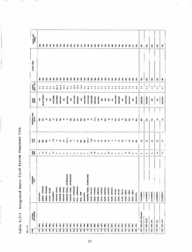
P
c
8
I 1 1 II
57
7.0 INTEGRATED WATER SYSTEM (IWS)
7.1 INTEGRATED WATER SYSTEM OVERALL REQUIREMENTS
The in t eg ra t ed water system w i l l be respons ib le f o r providing water t o the U.S. Laboratory, Japanese Experimental Module, Columbus Module and propulsion system. The system w i l l be capable of accept ing excess potable water from t h e Environmental Control and L i f e Support System (ECLSS) and the Orb i t e r and w i l l a l s o be capable of t r a n s f e r r i n g excess water t o the IWFS.
7.2 INTEGRATED WATER SYSTEM REQUIREMENTS
In tegra ted water system requirements are presented i n Table 7.2-1.
Table 7.2-1
Parameter
Growth 1)
In teg ra t ed Design 1)
I n t e r f a c e Hardware 1)
Fluid Storage a ) Requirements
2)
3)
In tegra ted Water System Requirments
Requirements
I O C systems shall have growth and on-orbit recon- f i g u r a t i o n c a p a b i l i t y t o accommodate changing demands i n user f l u i d quan t i t i e s . System shall incorporate sca r r ing t o accommodate add i t iona l i n t eg ra t ed system a t l o g i c a l f u l l opera t iona l capab i l i t y . System s h a l l be in t eg ra t ed t o minimize f l u i d management hardware development and opera t iona l cos t . F lu id i n t e r f a c e components shall be s tandardized and f l u i d t r a n s f e r i n t e r f a c e hardware s h a l l be designed t o preclude mating t o the wrong connector. A f l u i d quant i ty measurement c a p a b i l i t y shall be provided i n both the s torage and resupply sys tems . Leak de tec t ion , i s o l a t i o n , and con t ro l s h a l l be provided and shall comply with s t a t i o n environ- mental and contamination requirements. No l i q u i d s w i l l be vented overboard.
7.3 INTEGRATED WATER SYSTEM DESCRIPTION AND CONFIGURATION
A schematic of the IWS is presented i n Figure 7.3-1. The IWS w i l l cap ture a l l water ava i l ab le from the NSTS Orb i t e r , the ECLSS and, i f necessary, water resuppl ied from the Log i s t i c s module t o meet water resupply requirements. The system w i l l c o n s i s t of a c o l l e c t i o n subsystem, a s torage subsystem, and a d i s t r i b u t i o n subsystem t o supply a l l s t a t i o n use r s including the United S t a t e s Laboratory, Japanese Experimental Module, Columbus, Propulsion, and the In tegra ted Waste Flu id System. The bladder type water s to rage tanks of the IWS w i l l be pressur ized by n i t rogen from t h e in t eg ra t ed n i t rogen system. When the water tanks are resuppl ied, excess n i t rogen pressurant w i l l be channeled t o the in t eg ra t ed waste f l u i d system f o r propuls ive d isposa l . An a l t e r n a t e so lu t ion t o disposing the water would be t o channel it through the e l e c t r o l y s i s u n i t f o r a more e f f i c i e n t means of propuls ive d i sposa l through the oxygen/hydrogen t h r u s t e r s .

30 p s i a ............................................. DISTRIBUTION . Regulated down
SUPPLY i MULTIPLE I TANK .......
!ASSEMBLIES
RE SUP PLY . 1 MULTIPLE 6 i TANK
10 t o 30 ps ia
( 4 5 psia t o r e s i s t o j e t s )
PROPULSION^ i l o v pressure:50 ps ia
. . approx. : diaphram tank
JEM P = TBD ORBITER
............................................. STORAGE (2 LOCATIONS) : P = 100 ps ia
Storage Conditions RESUPPLY LO t o 30 p s i a
P - TBD I n l e t Conditions
10 to 20 psia
Out le t Conditions 10 t o 30 p s i a
BOSCH OR SABATIER ’ BOSCH : 7 . 4 3 lbmlday p - 44.9 poia SABATIER : 2.08 lbmlday
Figure 7.3-1 Schematic of the In t eg ra t ed Water System
Parameters t h a t a f f e c t the water balance of the i n t e g r a t i o n system are l i s t e d i n Table 7.3-1.
Table 7.3-1 Var iab les t h a t Affect Space S t a t i o n Water Balance and the Basel ine Configuration
Parameters Baseline Configuration
C02 Reduction Process i n ECLSS S t a t i o n C r e w S ize EVA’S per 90 days EVA dura t ion EMU Loop Closure Food Water Content (lbm/man/day) Orb i t e r Crew S ize Orb i t e r C r e w on S t a t i o n Orb i t e r Power Level (kW) Orb i t e r Stay Duration (days) Orb i t e r Visits per 90 Days Percentage of Water Recovery
from Laboratory Experiments
Bosch 8
39 6
Closed 1.1
4 10.0
5 2
85%
a
59
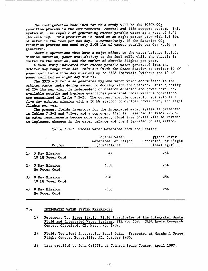
The conf igura t ion basel ined f o r t h i s study w i l l be the BOSCH C02 reduct ion process i n the environmental con t ro l and l i f e support system. system w i l l be capable of generat ing excess potable water a t a rate of 7.43 lbm each day. of water i n the food per man day. reduct ion process w a s used only 2.08 lbm of excess potable per day would be generated.
mission dura t ion , power a v a i l a b i l i t y t o the f u e l ce l l s while the s h u t t l e is docked t o the s t a t i o n , and the number of s h u t t l e f l i g h t s per year.
A NASA study indica ted t h a t excess potable water generated from the Orb i t e r may range from 342 l bm/v i s i t (wi th the Space S t a t i o n t o o r b i t e r 10 kW power cord f o r a f i v e day mission) up t o 2538 l bm/v i s i t (without the 10 kW power cord f o r an e i g h t day v i s i t ) .
The NSTS o r b i t e r a l s o genera tes hygiene water which accumulates i n the o r b i t e r waste tanks during ascent t o docking with the S ta t ion . of 254 lbm per v i s i t is independent of mission du ra t ion and power cord use. Avai lable potable and hygiene q u a n t i t i e s generated under var ious operat ions are summarized i n Table 7.3-2. The cu r ren t s h u t t l e operat ion scenar io i s a f i v e day o r b i t e r mission with a 10 kW s t a t i o n t o o r b i t e r power cord, and e i g h t f l i g h t s per year.
The present f l u i d s inventory f o r t he in t eg ra t ed water system i s presented i n Tables 7.3-3 and 7.3-4, and a component list i s presented i n Table 7.3-5. A s water requirements become more apparent , f l u i d inven to r i e s w i l l be rev ised t o implement changes i n the water balance and the in t eg ra t ed configurat ion.
This
This p red ic t ion i s based on an e i g h t person crew with 1.1 lbm Al t e rna t ive ly , i f the Saba t i e r C02
S h u t t l e opera t ions t h a t have a major e f f e c t on the water balance include
This quant i ty
Table 7.3-2 Excess Water Generated from the Orb i t e r
Potable Water Hygiene Water Generated Per F l i g h t
Option (lbm/f l i g h t ) ( l bm/ f l igh t ) Generated Per F l i g h t
1) 5 Day Mission 10 kW Power Cord
2) 5 Day Mission No Power Cord
3) 8 Day Mission 10 kW Power Cord
4) 8 Day Mission No Power Cord
342 254
1860 254
2040 254
2538 254
7.4 INTEGRATED WATER SYSTEM REFERENCES
1) Peterson, T., Space S t a t i o n F lu id Inven to r i e s of the In tegra ted Waste Fluid and In tegra ted Water Systems, P I R No. 159. NASA L e w i s Research Center, Cleveland, OH, March 25, 1987.
2) Flu ids Technical In t eg ra t ion Panel Data. Presented a t Marshall Space F l i g h t Center, Huntsv i l le , AL, October 1986.
3) Data provided by John G r i f f i n a t Johnson Space Center, Apr i l 1987.
60
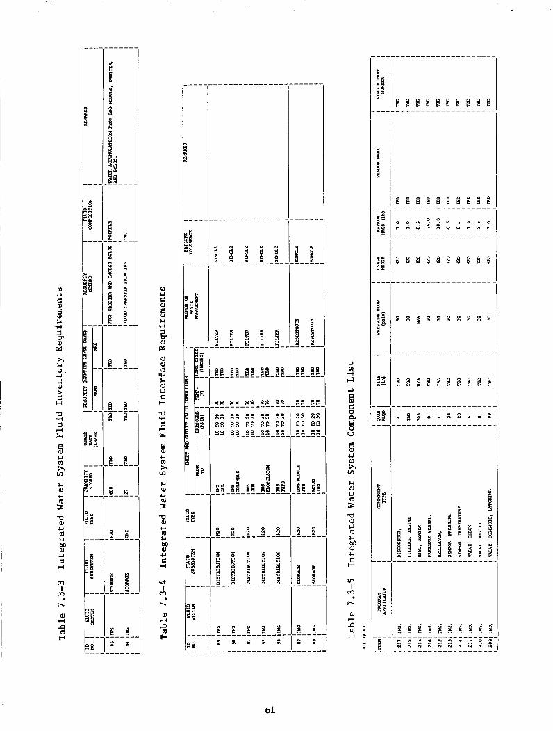
61
8.0 INTEGRATED NITROGEN SYSTEM ( INS
8.1 INTEGRATED NITROGEN SYSTEM OVERALL REQUIREMENTS
A t I O C , t he INS w i l l provide n i t rogen t o the Environmental Control and Life Support System (ECLSS), In tegra ted Waste Flu id System (IWFS) , In tegra ted Water System (IWS), U.S. Laboratory (USL), Columbus, and the Japanese Experimental Module (JEM). requirements r e l a t i v e t o Extravehicular Ac t iv i ty (EVA) Systems such as the Extravehicular Excursion Unit (EEU) and the Enhanced Mobil i ty Unit (EMU) with add i t iona l high pressure requirements f o r t h e O r b i t a l Maneuvering Vehicle (OW) and the Serv ic ing F a c i l i t y . s ca r r ing of the INS f o r a low pressure po r t f o r pos t I O C .
The INS w i l l be scar red a t I O C f o r high pressure
The Servicing F a c i l i t y w i l l a l s o r equ i r e
8.2 INTEGRATED NITROGEN SYSTEM REQUIREMENTS
Fluid system requirements f o r the in t eg ra t ed n i t rogen system are presented i n Table 8.2-1.
Table 8.2-1 In t eg ra t ed Nitrogen System Fluid System Requirements
Parameter
Growth
In tegra ted Design
2)
1 )
I n t e r f a c e Hardware 1 )
F lu id Storage 1)
Requirements
I O C systems s h a l l have growth and on-orbit reconf igura t ion c a p a b i l i t y t o accommodate changing demands i n user f l u i d q u a n t i t i e s .
System shall incorporate sca r r ing t o accommodate a d d i t i o n a l i n t eg ra t ed system a t l o g i c a l f u l l opera t iona l capab i l i t y .
System s h a l l be in t eg ra t ed t o minimize f l u i d management hardware development and opera t iona l cost .
Fluid i n t e r f a c e components s h a l l be s tandardized and f l u i d t r a n s f e r i n t e r f a c e hardware s h a l l be designed t o preclude mating t o the wrong connector.
A gas quantitEmeasurement c a p a b i l i t y s h a l l b e ' provided i n both the s torage and resupply subsystems.
8.3 INTEGRATED NITROGEN SYSTEM DESCRIPTION AND CONFIGURATION
The INS w i l l c o n s i s t of a resupply subsystem, emergency s to rage subsystem, and a d i s t r i b u t i o n subsystem, and w i l l include a l l hardware and software required t o provide the func t ions of resupply, t r a n s f e r , s to rage , condi t ion ing , d i s t r i b u t i o n , as w e l l as con t ro l and monitoring of the n i t rogen wi th in the INS. resupply requirements are shown in Table 8.3-1 and the INS f l u i d i n t e r f a c e requirements a r e shown i n Table 8.3-2.
A func t iona l diagram is shown as Figure 8.3-1. The INS f l u i d
62
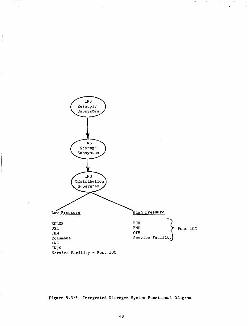
Resupply
Storage
Post 1oc Serv ice
ECLSS EEU
JEM OTV Columbus IWS IWFS Serv ice F a c i l i t y - Post 1 o C
USL EMU
Figure 8.3-1 In t eg ra t ed Nitrogen System Funct ional Diagram
63
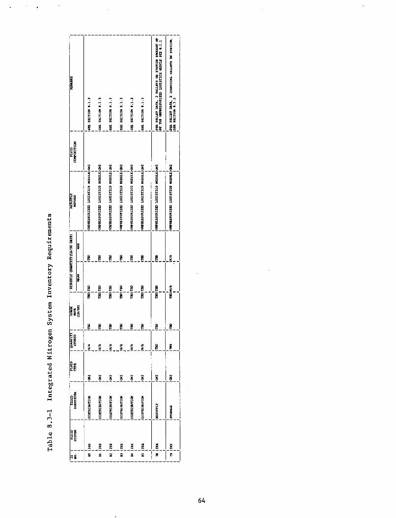
m U
$ 8
% l-4 .rl
PI cr: h L.l 0 U
$
e
3 c H
al u cn h VI
e al M 0 & u r( z a al U a & M al U C H
rl I
m
co al rl P a H
1 l : l l :
8 8 8 8 8 8
64
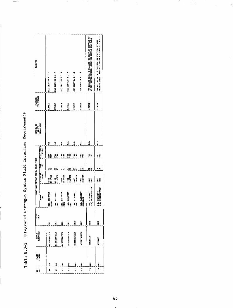
O ? ? ? ? ?
65

8.3.1 Resupply Subsystem
The INS resupply subsystem w i l l c o n s i s t of the tankage, mounting hardware, condi t ioning, thermal cont ro l , t r a n s f e r , and con t ro l and monitoring hardware f o r de l ive ry of the n i t rogen t o the Space S t a t i o n (SS). The resupply hardware w i l l be in t eg ra t ed and de l ivered t o the SS by the L o g i s t i c s System. The INS resupply subsystem w i l l be capable of being loca ted a t two i n t e r f a c e loca t ions on t he t r u s s t h a t are optimized f o r on-orbit opera t ions including EVA operat ions. The INS resupply subsystem performs the dua l func t ion of resupply and s torage of the n i t rogen de l ivered t o SS t o s a t i s f y a l l user requirements. The resupply subsystem w i l l be a GN2 blowdown supply system t h a t a t f u l l tankage condi t ions is a t 3000 t o 4000 p s i t o optimize tankage mass f r ac t ion . A t dep le t ion of t he first p a l l e t the second resupply p a l l e t mounted on s t a t i o n would take over t h e resupply opera t ion and the depleted p a l l e t would be removed and replaced. subsystem wi th the corresponding components l i s t i n g shown as Table 8.3-3.
Figure 8.3-2 shows the schematic of t he INS resupply
8.3.2 Storage Subsystem
The INS s torage subsystem w i l l provide s u f f i c i e n t s torage capac i ty t o s a t i s f y emergency ECLSS requirements f o r hyperbaric a i r l o c k and safe-haven operat ions. The INS s torage subsystem is loca ted ex te rna l t o the modules i n t he t ru s s . Each p a l l e t w i l l r e t a i n 780 lbm of GN2 s to red a t 3000 t o 4000 p s i and used only f o r safe haven o r hyperbaric a i r l o c k operat ions. schematic is shown as Figure 8.3-3 wi th the corresponding components l i s t shown as Table 8.3-4.
The
8.3.3 D i s t r i b u t i o n Subsvstem
The INS d i s t r i b u t i o n subsystem w i l l t r a n s f e r t h e n i t rogen from the INS s torage subsystem a t 3000 t o 4000 p s i and w i l l reduce the pressure t o 250 t o 750 p s i f o r low pressure use and w i l l then route the n i t rogen t o the var ious use r i n t e r f aces . The INS d i s t r i b u t i o n subsystem c o n s i s t s of t he plumbing, connectors, thermal con t ro l , condi t ioning, s t r u c t u r a l attachment, and con t ro l and monitoring hardware t o d i s t r i b u t e n i t rogen t o both high and low pressure users . All high pressure use r s a t the present time a r e pos t 1OC and the re fo re the INS is scarred f o r eventual high pressure app l i ca t ions as indica ted . The schematic shown as Figure 8.3-4 reflects the p o t e n t i a l hardware t o reduce the 3000 t o 4000 p s i supply t o 3000 p s i f o r use, but is only a t e n t a t i v e so lu t ion pending f u r t h e r requirement de f in i t i on . shown as Table 8.3-5 list the sca r r ing requirements and not t he p o t e n t i a l f u t u r e growth hardware. both i n t e r n a l t o the pressur ized po r t ions of SS as w e l l as eventual f u t u r e growth e x t e r n a l l y along the t r u s s system t o supply the Servicing F a c i l i t y and OMV requirements.
For t h i s reason the component l i s t i n g
The INS d i s t r i b u t i o n subsystem and w i l l be loca ted
8.4 INTEGRATED NITROGEN SYSTEM REFERENCES
1) Arch i t ec tu ra l Control Document F lu id Management System; Sec t ion 1: In tegra ted Nitrogen System, NASA JSC 30264. December 1, 1986.
2) Space S t a t i o n Program Def in i t i on and Requirements, Sec t ion 3, System Requirements Rev. A, SS-SRD-0001. January 12, 1987.
66
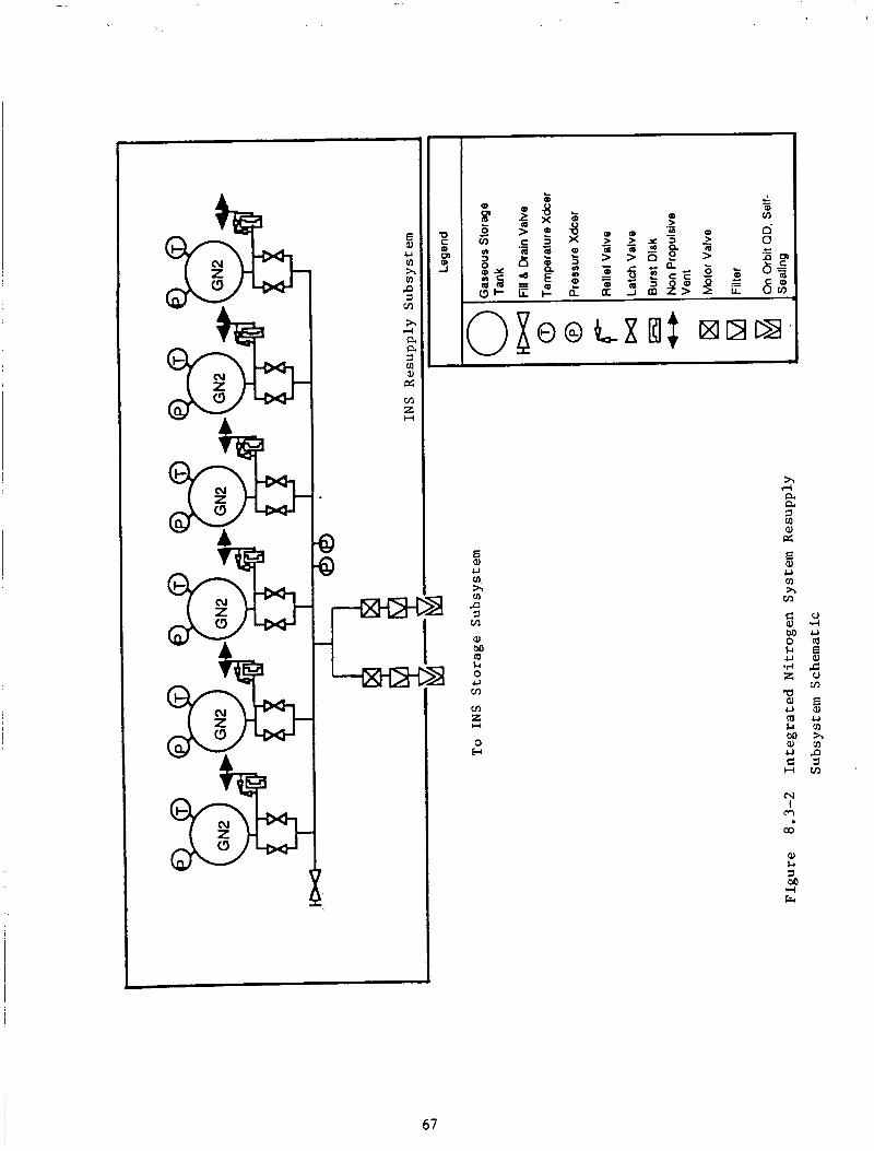
h
8 U cn h cn P 3 VI
Ll 0 U m m z H
0 w
a =I rn Q)
3 U cn h m
m a
67
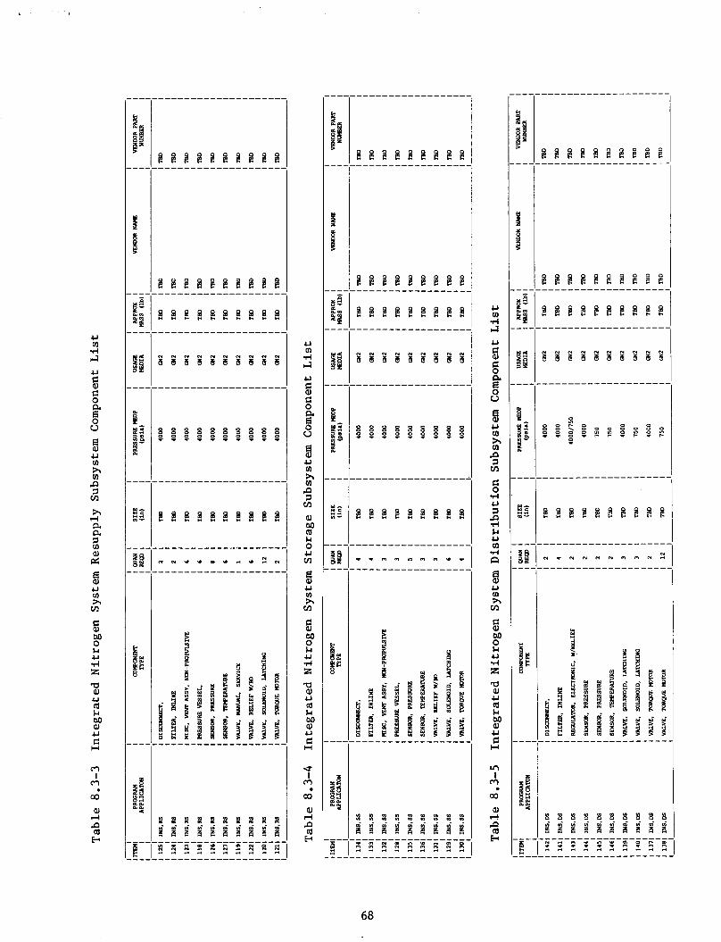
U m d 4 U
?i g 2
g
0 U
U m h m P 3 rn h rl a a 2 2 8
ti
U m h rn
M 0 t-l U d z a aJ U (d t-l M aJ U C H
m I
m a aJ d P tu b
.
% & & & E & & % & &
U rn d l-l
U
?i g
8
a E 0 u
U rn h rn P 3 rn 0) M tu t-l 0 U rn
al U u) h rn
e
5 M 0 Ll U d z a aJ U (d t-l M 01 U C H
U I
m m aJ d P (d w
.
X X X 8 S S X 8 X 9 1 1 9 8 9 9 9 3
U rn d 4 U
?i Ei $
5 0 u
U rn h rn P 7 rn
g
f l
d U 7
t-l U m d a
U cn h rn
ci M 0 t-l U d z a aJ U tu t-l M al U C H
In I
a al d
tu w
?
a
9 9
68

8 U 111 h v)
3 m h
rt a e 3 0 9) d m z l-l
0 w
n
t9 a
I
5 5 u 111
n 3 m C 0 d 4-l 3
M u v) d
R
n m Ei 0 w
m 5
5 u v) h VI
a a, U m $4 M al U C H
m I
m
69
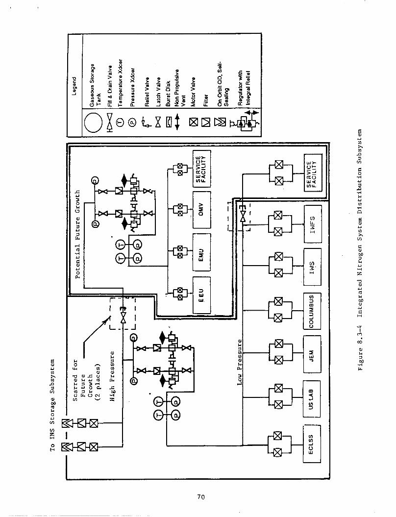
1
i-- I
. J
n
T 70
rJY h rJY
3 m n
h U v) .rl
. n E a, U v) h VI
5 M 0
al U c: H
U I m
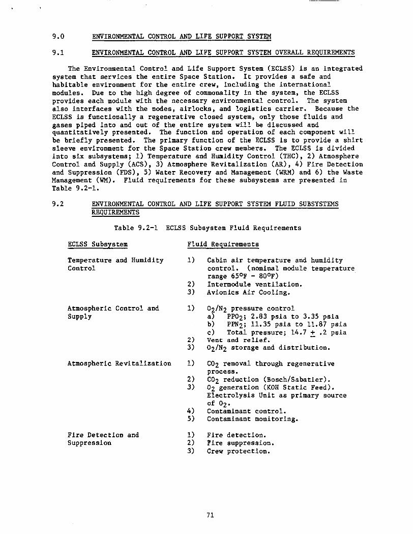
9.0 ENVIRONMENTAL CONTROL AND LIFE SUPPORT SYSTEM
9.1 ENVIRONMENTAL CONTROL AND LIFE SUPPORT SYSTEM OVERALL REQUIREMENTS
The Environmental Control and L i f e Support System (ECLSS) is an in t eg ra t ed system t h a t s e rv i ces the e n t i r e Space S ta t ion . It provides a s a f e and habi tab le environment f o r t h e e n t i r e crew, including the i n t e r n a t i o n a l modules. Due t o the high degree of commonality i n the system, the ECLSS provides each module with the necessary environmental cont ro l . The system a l s o i n t e r f a c e s with the nodes, a i r l o c k s , and l o g i s t i c s carrier. Because the ECLSS is func t iona l ly a regenerat ive closed system, only those f l u i d s and gases piped i n t o and out of the e n t i r e system w i l l be discussed and q u a n t i t a t i v e l y presented. be b r i e f l y presented. The primary func t ion of the ECLSS is t o provide a s h i r t s leeve environment f o r t he Space S t a t i o n crew members. i n t o six subsystems; 1) Temperature and Humidity Control (THC), 2) Atmosphere Control and Supply (ACS), 3) Atmosphere R e v i t a l i z a t i o n (AR), 4) F i re Detect ion and Suppression (FDS), 5) Water Recovery and Management (WRM) and 6) the Waste Management (WM). Fluid requirements f o r these subsystems a r e presented i n Table 9.2-1.
The func t ion and opera t ion of each component w i l l
The ECLSS is divided
9.2 ENV1RO"TAL CONTROL AND LIFE SUPPORT SYSTEM FLUID SUBSYSTEMS REQUIREMENTS
Table 9.2-1 ECLSS Subsystem Flu id Requirements
ECLSS Subsystem Flu id Requirements
Temperature and Humidity 1 ) Control
2) 3)
Atmospheric Control and 1) Supply
2) 3)
Atmospheric Rev i t a l i za t ion 1)
F i r e Detection and Suppression
1) 2) 3)
Cabin a i r temperature and humidity cont ro l . (nominal module temperature range 65OF - 80°F) Intermodule ven t i l a t ion . Avionics A i r Cooling.
02 a) b)
, / N 2 p ressure con t ro l PP02; 2.83 p s i a t o 3.35 p s i a PPN2; 11.35 p s i a t o 11.87 p s i a To ta l pressure; 14.7 - + .2 p s i a c )
Vent and relief. 02/N2 s torage and d i s t r i b u t i o n .
C02 removal through regenera t ive process. C02 reduct ion (Bosch/Sabatier) . 02 genera t ion (KOH S t a t i c Feed). E l e c t r o l y s i s Unit as primary source
Contaminant cont ro l . Contaminant monitoring.
of 02.
F i r e de tec t ion . Pire suppression. C r e w pro tec t ion .
71
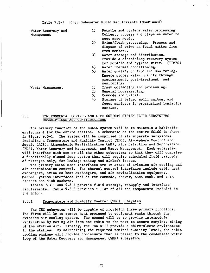
Table 9.2-1 ECLSS Subsystem Fluid Requirements (Continued)
Water Recovery and 1)
2)
Management
3)
4 ) 5 )
Waste Management
Potable and hygiene water processing. Co l l ec t , process and dispense water t o meet crew needs. Urine/f lush processing. Process and dispose of ur ine an f e c a l matter from crew members. Water s torage and d i s t r i b u t i o n . Provide a closed-loop recovery system f o r potable and hygiene water. Water thermal conditioning. Water q u a l i t y con t ro l and monitoring. Ensure proper water qua l i t y through pretreatment , post-treatment, and monitoring. Trash c o l l e c t i n g and processing. General housekeeping. Commode and Urinal. Storage of br ine, so l id carbon, and f e c e s c a n i s t e r i n pressurized l o g i s t i c s carrier.
(TIMES)
9 .3 ENVIRONMENTAL CONTROL AND LIFE SUPPORT SYSTEM FLUID SUBSYSTEMS DESCRIPTIONS AND CONFIGURATIONS
The primary func t ion of the ECLSS system w i l l be t o maintain a hab i t ab le environment f o r the e n t i r e s t a t i o n . A schematic of the e n t i r e ECLSS is shown i n Figure 9.3-1. inc luding a Temperature and Humidity Control (THC), Atmosphere Control and Supply (ACS), Atmospheric R e v i t a l i z a t i o n (AR), F i r e Detect ion and Suppression (FDS), Water Recovery and Management, and Waste Management. w i l l i n t e r f a c e with one o r a l l t h e o the r subsystems so t h a t they w i l l comprise a func t iona l ly closed loop system t h a t w i l l r equ i r e scheduled f l u i d resupply of n i t rogen only, f o r leakage makeup and a i r l o c k losses .
a i r contamination cont ro l . The thermal c o n t r o l i n t e r f a c e s include cabin hea t exchangers, av ionics hea t exchangers, and a i r r e v i t a l i z a t i o n equipment. Manned Systems i n t e r f a c e s include the commode, shower, hand wash, and both c lo thes and d i s h washers.
Tables 9.3-1 and 9.3-2 provide f l u i d s torage , resupply and i n t e r f a c e requirements. the ECLSS.
The system w i l l be comprised of s i x separa te subsystems
Each subsystem
The primary ECLSS user i n t e r f a c e s are i n areas of av ionics a i r cool ing and
Table 9.3-3 provides a l i s t of a l l the components included i n
9.3.1 Temperature and Humidity Control (THC) Subsystem
The THC subsystem w i l l be capable of providing th ree primary funct ions. The first w i l l be t o remove hea t produced by equipment racks through the av ionics a i r cool ing system. v e n t i l a t i o n by moving a i r from one cabin t o the next t o ensure complete mixing of the s t a t i o n a i r . F ina l ly , t he THC w i l l provide a sh i r t - s leeve environment i n the s t a t ion . By maintaining the required nominal humidity l e v e l , t he cabin cool ing package w i l l provide condensate t h a t i s passed t o the condensate water loop of the Water Recovery and Management (WRM) subsystem.
The second w i l l be t o provide intermodule
7 2
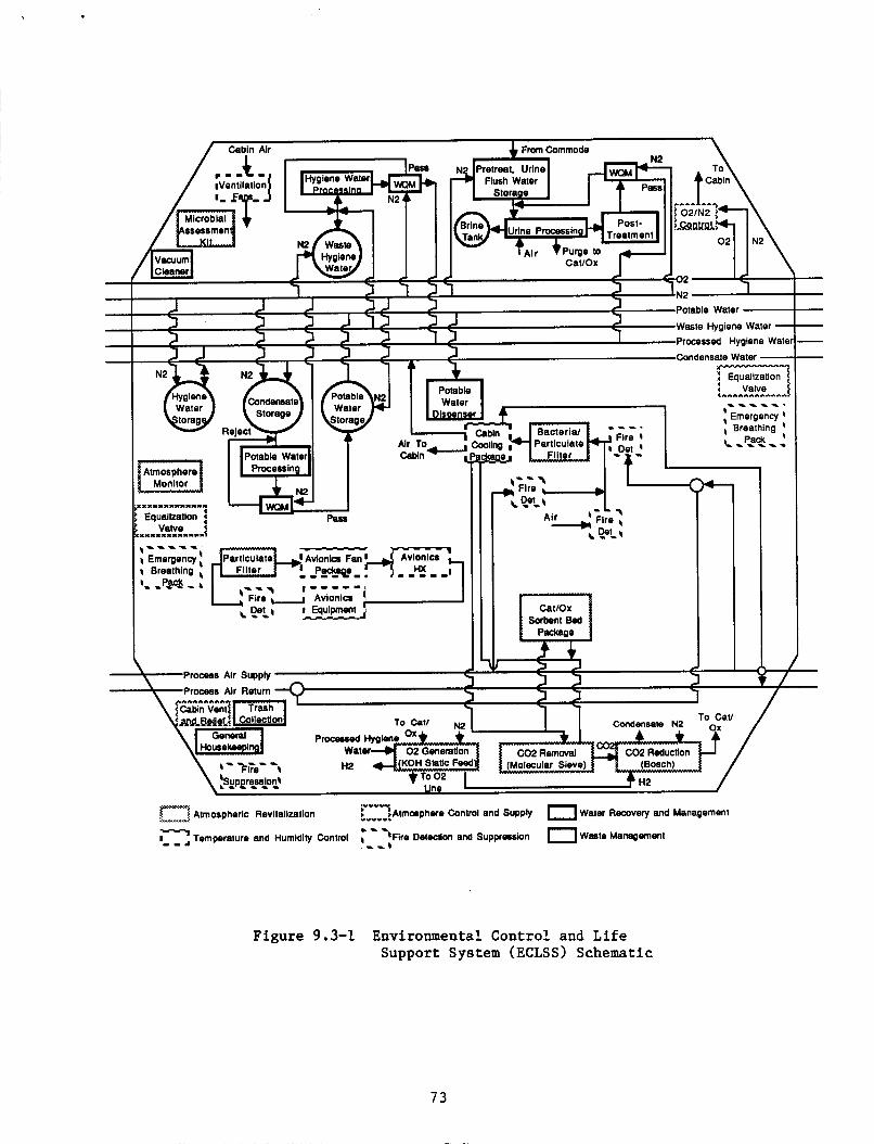
Processed Hygiene Wal
J J Condensate Water - r""""""""M"
Equalization x Valve Potable
Water _ _ _ - _ . nser Emergency I
, Breathing ~
I.......................
Air? , 1 1 1 1 Pmrtlriilatn c -?E!!- - Cabin-,
Process Air Supply e Process Air Return A T
Atmospheric Revitalization ~ v ~ w ~ ~ A t m o 6 p h e r e Control and Supply 0 Water Recovery and Management
c-- Temperature and Humidity Control Detection and Supprocrsion 0 Waste Managmen1
7-
Figure 9.3-1 Environmental Control and Life Support System (ECLSS) Schematic
73

I
il % I X P X _ _ _ _ _ _ _ _ _ _ _ _ _ _ - _ -
_ _ _ _ _ _ _ _ _ _ _ _ _ _ _ _ -
4 z w
74
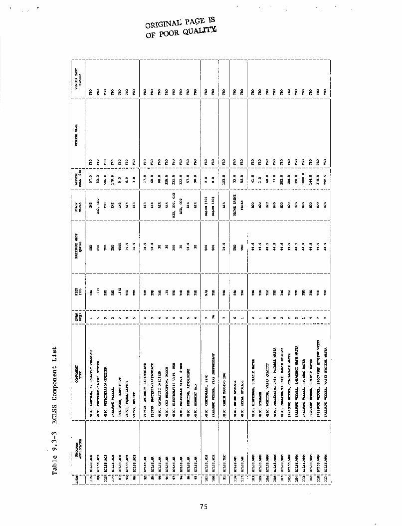
f c
I
L) m .rl +l
9 9 N . D
p p d d
8 8
5 &
9 : I z : 9 9
I E 8 8
75
9.3 .2 Atmosphere Control and Supply (ACS) Subsystem
The ACS subsystem w i l l maintain the p a r t i a l and t o t a l p ressures of 02 and N 2 i n the modules and w i l l be respons ib le f o r s torage and d i s t r i b u t i o n of both 02 and N2. a i r l o c k lo s ses , tank back pressur iza t ion /water t r a n s f e r , and purge f o r t he a i r r e v i t a l i z a t i o n and waste management systems.
The oxygen required f o r d a i l y use, i.e., leakage makeup and a i r l o c k uses w i l l be generated by the e l e c t r o l y s i s u n i t i n the Atmospheric R e v i t a l i z a t i o n (AR) subsystem. n i t rogen required f o r d a i l y use w i l l be s tored as p a r t of the In tegra ted Nitrogen System (INS) resupply subsystem (see Sect ion 8.1-1). s torage w i l l a l s o be provided f o r safe-haven o r emergency condi t ions as p a r t of the INS s torage subsystem. safe-haven o r emergency condi t ions t h a t will r equ i r e resupply only i f the oxygen is exhausted during adverse condi t ions. be d i s t r i b u t e d t o the ACS subsystem as needed a t 180-200 p s i a and 200-250 p s i a respec t ive 1 y .
The ACS subsystem provides N2 f o r leakage makeup,
This oxygen w i l l be s tored i n accumulators a t 3000 psia . The
Nitrogen
There w i l l be an oxygen s torage tank f o r
The oxygen and n i t rogen w i l l
9.3 .3 Atmospheric R e v i t a l i z a t i o n (AR) Subsystem
The AR subsystem w i l l perform seve ra l v i t a l funct ions. The f i r s t w i l l be t o both monitor and c o n t r o l any contaminants i n the modules. The o the r func t ions w i l l i n t e r f a c e w i t h both the WM and ACS subsystems. The AR subsystem w i l l genera te oxygen using a KOH S t a t i c Feed E l e c t r o l y s i s Unit. To do t h i s , the u n i t w i l l use processed hygiene water from the WRM subsystem and N2 from the ACS subsystem. ACS 02 l i n e , and the hydrogen w i l l be t r ans fe r r ed t o the C02 reduct ion system as needed, with the remaining H2 going t o the In tegra ted Waste F lu id System.
The AR subsystem w i l l a l s o remove C02 from the atmosphere using a Four-Bed Molecular Sieve. The C02 t h a t is co l l ec t ed during the C02 removal i n the molecular s i eve w i l l then be reduced i n the C02 reduct ion u n i t . This w i l l be accomplished using e i t h e r a Bosch Carbon Reactor o r a Saba t i e r Methanation Reactor Subsystem.
put i n t o the WRM condensate water l i n e . r e a c t i o n w i l l be acquired from the e l e c t r o l y s i s un i t .
As with the Bosch, the condensed water from the Saba t i e r process w i l l be t r ans fe r r ed i n t o the condensate l i n e of t he WRM subsystem. The methane w i l l be t r ans fe r r ed t o the In tegra ted Waste Flu id System f o r appropr ia te d i sposa l .
The oxygen produced w i l l be t r ans fe r r ed t o the
During the C02 removal process i n the Bosch, t he water condensed w i l l be The hydrogen required f o r the
9.3 .4 F i r e Detection and Suppression (FDS) Subsystem
The FDS subsystem w i l l be f u l l y charged when brought onboard and w i l l no t requi re resupply. passed through the FDS subsystem f o r d e t e c t i o n of poss ib le f i r e s before en te r ing the cabin cool ing package. i n any way. The a i r w i l l r e t u r n t o the cabin o r process a i r r e t u r n duc t , o r s en t t o the C02 removal system as needed.
A i r from the cabin and the process a i r supply w i l l be
The FDS subsystem w i l l not a l t e r the a i r
76

9.3.5 Water Recovery and Management (WRM) Subsystem
The WRM subsystem w i l l i n t e r f a c e with t h e THC, the ACS, and the AR .
The WRM w i l l be a closed loop system t h a t does not r equ i r e subsystems. resupply. I n f a c t , t he WRM subsystem w i l l supply excess water t o the in t eg ra t ed waste system. form of moisture i n the food. through p e r s p i r a t i o n and ur ine. cool ing loop and e n t e r t he condensate loop t o be processed f o r potable water. The u r ine w i l l e n t e r the u r ine processing loop.
For the ur ine processing, the TIMES, a d i s t i l l a t i on -based u n i t using membrane evaporat ion f o r unique phase separa t ion w i l l be used. w i l l e n t e r t h e u n i t and be preheated by a regenera t ive hea t exchanger, f i l t e r e d and heated by a Thermoelectric Device (TED) t o opera t ing temperature. (HFM) evaporator module where a por t ion of the consul tan t water w i l l be evaporated i n t o steam. The bulk of water not turned t o steam w i l l continuously recycled through the module u n t i l the s o l i d s concent ra t ion reaches a predetermined l i m i t i n g l e v e l a t which t i m e t h i s br ine w i l l be dumped t o a c o l l e c t i o n tank. The br ine c o l l e c t i o n tank w i l l be p a r t of the waste management subsystem. The tanks w i l l be loca ted near t he TIMES and changed out when f u l l . The f u l l b r ine tanks w i l l be s tored i n the Pressurized L o g i s t i c s Module. The product steam w i l l f low t o the cold s i d e of the TED where most of the steam w i l l be condensed and the l a t e n t hea t reclaimed and t r ans fe r r ed back t o the waste water hea t ing s i d e of the TED.
Addit ional condensation w i l l occur i n the regenera t ive hea t exchanger and complete steam condensation w i l l occur i n the fan-cooled hea t exchanger. The presence of noncondensible gases and condensate w i l l r e s u l t i n a two-phase mixture r equ i r ing a gas-liquid separa tor . The separated noncondensible gases w i l l be vented t o a vacuum source and the pressurized condensate checked f o r conduct ivi ty . Acceptable condensate w i l l be passed t o the processed hygiene loop. Reject water w i l l be re turned t o the recyc le loop. A pulse valve/pressure sensor combination w i l l ensure optimum opera t ing steam pressure i n the evaporator.
e l e c t r o l y s i s . l a t e n t loads from laundry, dishwash, and hygiene w a t e r i n the form of condensate. Excess potable can a l s o be t r ans fe r r ed t o the hygiene loop i f needed.
The source of the water f o r t he WRM w i l l be i n the The moisture w i l l e n t e r t h e WRM subsystem
The pe r sp i r a t ion w i l l condense i n the cabin
Waste water
The waste water w i l l be passed through the Hollow F i b e r Membrane
A gas o r i f i c e w i l l be provided t o minimize pressure pulses . The processed hygiene water w i l l be used f o r wash purposes and water
The hygiene water can be put back i n t o the potable loop by
9.3.6 Waste Management (WM) Subsystem
The WM subsystem w i l l include the commode and u r i n a l which i n t e r f a c e with WRM subsystem. The WM subsystem w i l l provide s torage f o r t he waste products of both the WRM and AR subsystems. The WM subsystem w i l l s t o r e the ur ine br ine , f e c e s c a n i s t e r s , and carbon produced i n the C02 reduct ion u n i t i n the pressur ized l o g i s t i c s carrier.
7 7
,
9.4 ENVIRONMENTAL CONTROL AND LIFE SUPPORT SYSTEM REFERENCES
Space S t a t i o n Def in i t i on and Preliminary Design, WP-01, Book 3 - U.S. Lab Module. SSP-MMC-00031 (Rev. B) NAS8-36525. Martin Mar ie t ta Denver Aerospace, October 1986.
Space S t a t i o n Def in i t i on and Prel iminary Design, WP-01, Book 10 Air locks. SSP-MMC-00031 (Rev. A ) , NAS8-36525. Martin Marietta Denver Aerospace, June 1986.
Larkins, J. T., Wagner, R. C., and Gopikanth, M. L., A Space S t a t i o n U t i l i t y - S t a t i c Feed Elec t ro lyzer . Systems, Inc. , J u l y 1986.
Presented a t ICES Conference, L i f e
Data submitted by J i m Reuter, Marshall Space F l i g h t Center, Huntsv i l le , AL, Apr i l 30, 1987.
F lu ids Technical I n t e g r a t i o n P a n e l Data. F l i g h t Center, Huntsv i l le , AL, October 1986.
Presented a t Marshall Space
78
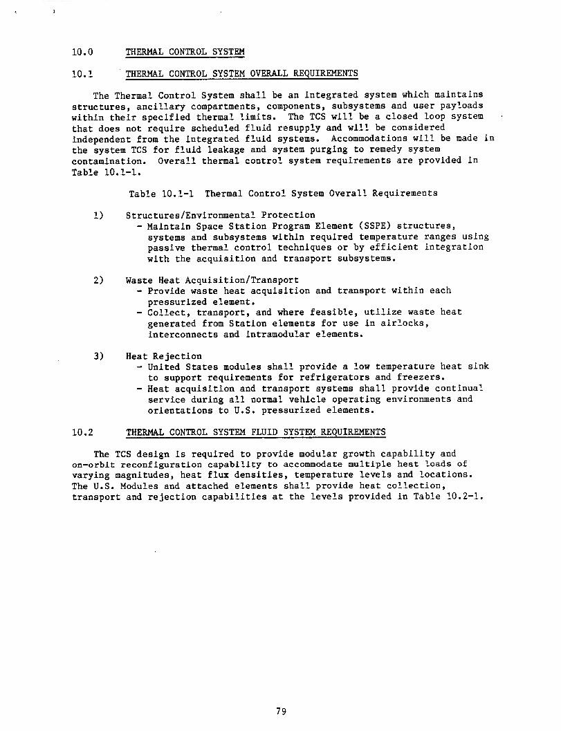
10.0 THERMAL CONTROL SYSTEM
10.1 THERMAL CONTROL SYSTEM OVERALL REQUIREMENTS
The Thermal Control System s h a l l be an in t eg ra t ed system which maintains s t r u c t u r e s , a n c i l l a r y compartments, components, subsystems and user payloads within t h e i r spec i f i ed thermal l i m i t s . The TCS w i l l be a closed loop system t h a t does not r equ i r e scheduled f l u i d resupply and w i l l be considered independent from the in t eg ra t ed f l u i d systems. the system TCS f o r f l u i d leakage and system purging t o remedy system contamination. Overal l thermal con t ro l system requirements a r e provided i n Table 10.1-1.
I
Accommodations w i l l be made i n
Table 10.1-1 Thermal Control System Overal l Requirements
1)
2)
3)
10.2
S t ruc tu res /Environmental Pro tec t ion - Maintain Space S t a t i o n Program Element (SSPE) s t r u c t u r e s ,
systems and subsystems within required temperature ranges using passive thermal con t ro l techniques o r by e f f i c i e n t i n t eg ra t ion with the a c q u i s i t i o n and t r anspor t subsystems.
Waste Heat Acquis i t ion/Transport - Provide waste hea t acqu i s i t i on and t r anspor t wi th in each
- Col l ec t , t r anspor t , and where f e a s i b l e , u t i l i z e waste hea t pressur ized element.
generated from S t a t i o n elements f o r use i n a i r l o c k s , in te rconnec ts and intramodular elements.
Heat Reject ion - United S t a t e s modules s h a l l provide a low temperature hea t s ink t o support requirements f o r r e f r i g e r a t o r s and f r eeze r s .
- Heat a c q u i s i t i o n and t r anspor t systems s h a l l provide continua?. service during a l l normal vehicle operat ing environments and o r i e n t a t i o n s t o U.S. pressurized elements.
THERMAL CONTROL SYSTEM FLUID SYSTEM REQUIREMENTS
The TCS design i s required t o provide modular growth c a p a b i l i t y and on-orbit reconf igura t ion c a p a b i l i t y to accommodate m u l t i p l e hea t l o a d s of varying magnitudes, hea t f l u x d e n s i t i e s , temperature l e v e l s and loca t ions . The U.S. Modules and a t tached elements s h a l l provide hea t c o l l e c t i o n , t r anspor t and r e j e c t i o n c a p a b i l i t i e s a t the l e v e l s provided i n Table 10.2-1.
79
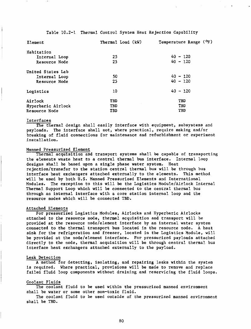
I
Table 10.2-1 Thermal Control System Heat Reject ion Capabi l i ty
Element Thermal Load (kW) Temperature Range (OF)
Habitat ion I n t e r n a l Loop Resource Node
United S t a t e s Lab I n t e r n a l Loop Re source Node
25 25
50 25
40 - 120 40 - 120
40 - 120 40 - 120
Logis t i c s 10 40 - 120
Airlock Hyperbaric Air lock R e source Node
TBD TBD TBD
TBD TBD TBD
I n t e r f a c e s
payloads. breaking of f l u i d connections f o r maintenance and refurbishment o r experiment i n s t a l l a t i o n .
The thermal des ign s h a l l e a s i l y i n t e r f a c e with equipment, subsystems and The i n t e r f a c e s h a l l not , where practical , r equ i r e making and/or
Manned Pressur ized Element
t he elements waste hea t t o a c e n t r a l thermal bus in t e r f ace . I n t e r n a l loop designs s h a l l be based upon a s i n g l e phase water system. r e j e c t i o n / t r a n s f e r t o the s t a t i o n c e n t r a l thermal bus w i l l be through bus i n t e r f a c e hea t exchangers a t tached e x t e r n a l l y t o the elements. This method w i l l be used by both U.S. Manned Pressurized Elements and I n t e r n a t i o n a l Modules. Thermal Support Loop which w i l l be connected t o the c e n t r a l thermal bus through an i n t e r n a l i n t e r f a c e with a core s t a t i o n i n t e r n a l loop and the resource nodes which w i l l be connected TBD.
Thermal a c q u i s i t i o n and t r anspor t systems s h a l l be capable of t r anspor t ing
Heat
The except ion t o t h i s w i l l be the L o g i s t i c s Module/Airlock I n t e r n a l
Attached Elements
a t tached t o the resource node, thermal a c q u i s i t i o n and t r a n s p o r t w i l l be provided a t the resource node/element i n t e r f a c e by an i n t e r n a l water system connected t o the thermal t r a n s p o r t bus located i n the resource node. A hea t s ink f o r t he r e f r i g e r a t i o n and f r e e z e r , loca ted i n the L o g i s t i c s Module, w i l l be provided a t the node/element i n t e r f ace . For pressur ized payloads a t tached d i r e c t l y t o the node, thermal a c q u i s i t i o n w i l l be through c e n t r a l thermal bus i n t e r f a c e hea t exchangers a t tached ex te rna l ly t o the payload.
For pressur ized L o g i s t i c s Modules, Air locks and Hyperbaric Air locks
Leak Detection A method f o r de t ec t ing , i s o l a t i n g , and r epa i r ing leaks wi th in the system
is required. Where p r a c t i c a l , p rovis ions w i l l be made t o remove and rep lace f a i l e d f l u i d loop components without dra in ing and r e se rv ic ing the f l u i d loops.
Coolant F lu ids The coolant f l u i d t o be used wi th in the pressurized manned environment
s h a l l be water o r some o the r non-toxic f luid:
s h a l l be TBD. The coolant f l u i d t o be used outs ide of the pressurized manned environment
80

10.3 THERMAL CONTROL SYSTEM FLUID SYSTEM DESCRIPTION AND CONFIGURATION
Manned Pressurized Elements The TCS of the U.S. Manned pressur ized elements and i n t e r n a t i o n a l modules
w i l l be similar i n conf igura t ion t o the USL Thermal Control System shown i n Figure 10.3-1. The system w i l l conta in three bas ic loops; a primary experiment loop, an a t tached payload loop and a r e f r i g e r a t i o d f r e e z e r loop.
The primary experiment loop w i l l be a pumped single-phase water coolant loop which w i l l service a l l four rack banks and w i l l be capable of r e j e c t i n g 50 kW of waste heat . av ion ic s hea t exchanger as w e l l as from subsystem/experiment cold p l a t e s and/or hea t exchangers mounted i n the racks. The 35OF loop w i l l c o l l e c t waste hea t from the cabin condensing hea t exchanger as w e l l as from subsystem/experiment cold p l a t e s and/or hea t exchangers. i n t e r f a c e w i l l only be provided down one s ide of the module due t o i t s l imi ted demand, pr imar i ly from the b io log ica l experiments. primary experiment loop w i l l be t r ans fe r r ed t o the Space S t a t i o n Heat Rejec t ion and Transport System (HR&T) through 70°F and 35OF c e n t r a l bus hea t exchangers mounted on t he e x t e r i o r of t he USL endcone s t r u c t u r e . Redundant pump packages w i l l be provided f o r s a fe ty .
equipment i n USL adjacent nodes and/or interconnects . pumped single-phase water.
body mounted r a d i a t o r s w i l l be provided t o reject the hea t necessary t o meet the -3OOC f r e e z e r requirement.
The 70°F loop w i l l c o l l e c t waste hea t from the
The 35OF coolant
USL waste hea t from t h i s
An a t tached payload loop, s ized f o r 25 kW, w i l l be provided t o cool This loop w i l l a l s o be
Ref r i g e r a t o r / f r eeze r s e rv i ces are required i n the USL. Low temperature
Air locks Fluid l i n e s w i l l be i n s t a l l e d i n the a i r l o c k s t o supply c h i l l e d water t o
atmospheric hea t exchangers. The c h i l l e d water w i l l be suppl ied t o the a i r l o c k s by the a t tached payload loop. The pump, con t ro l s , and hea t exchangers f o r the a t tached payload loop are loca ted i n the core modules. Temperature sensors w i l l be i n s t a l l e d a t the i n l e t and the o u t l e t of the atmospheric con t ro l hea t exchanger i n the a i r lock .
81

-1 r To Cent ra l Radiators,
I
Two Phase I Ammonia -e +
To Cen t ra l v Radiators
35 F
Two Phase
- Ammonia
, : I,
*-, .;I
LOW Temperature Body Mounted
Radiators I' x Lcr lo r
I ill c r io r '..*.Y,,,rr, ,,, ., . . . ., I (.. ,.. .,". 4 ,.
I Rel r lq /Freezer
Single-Phaso V a l c r I Avlonlcr p* Cabin
Condenslnp r-- 4
10 F o r w a r d Mod8 * 35 r SUPPIY
I 1 0 A l l Mode
Figure 10.3-1 USL Thermal Control System
82

10.4 THERMAL CONTROL SYSTEM REFERENCES
1) Space Station Definition and Preliminary Design, WP-01, Book 3, U.S . Lab Module, SSP-MMC-00031, Rev. B, NAS8-36525. Martin Marietta Denver Aerospace, Denver, CO., October 31, 1986.
2) Space Station Definition and Preliminary Design, WP-01, Book 2, Common Module. SSP-MMC-00031. Rev. B, NAS8-36525. Martin Marietta Denver Aerospace, Denver, CO., October 31, 1986.
3) Space Station Definition and Preliminary Design, WP-01, Book 10, Airlocks. SSP-MMC-00031. Rev. B, NAS8-36525. Martin Marietta Denver Aerospace, Denver, CO., October 31, 1986.
4) Space Station Program Definition and Requirements, Section 3 System Requirements, SS-SED-0001. Space Station Projects Office, Marshall Space Flight Center, Huntsville, AI,, January 12, 1987.
83
11.0 ATTACHED PAYLOADS
11.1 ATTACHED PAYLOADS OVERALL REQUIREMENTS
Overal l requirements f o r t he a t tached payloads are presented i n Table 11.1-1.
1)
2)
3)
4)
5 )
6 )
The
Table 11.1-1 Attached Payloads Overal l Requirements
Payloads w i l l be mounted on s t a t i o n a r y o r r o t a t i n g attachment provis ions on the Resource Nodes.
Tethered Deployment shall be considered as an a l t e r n a t i v e t o attachment f o r payloads with s e n s i t i v e environmental requirements.
I n t e r f a c e Monitoring and Protect ion. shall provide monitoring, measurement and p ro tec t ion of a l l i n t e r f a c e s t h a t provide da t a , power, cool ing, o r similar resources t o payloads such t h a t a payload f a i l u r e o r payload misuse of resources cannot r e s u l t i n adverse impact on o the r payload o r o ther operat ions.
Space S t a t i o n and platforms
Servicing - None
Contamination - None
Standard I n t e r f a c e s - I n t e r f a c e s s h a l l be s tandar ized appropr ia te ly so t h a t any payload can be e a s i l y interchangeable between the manned element and a t tached payload.
i n t e g r a t i o n of f l u i d s from a t tached payloads t o o ther Space S t a t i o n elements is p resen t ly an open i ssue . a t tached payloads does not r equ i r e f l u i d s t o be in tegra ted . 1986 time frame, the a t tached payloads community prefer red t o be autonomous because of poss ib le opera t iona l c o n s t r a i n t s imposed by i n t e r f a c i n g with the s t a t i o n during operation.
The a l t e r n a t i v e s t o i n t e r f a c i n g with the s t a t i o n are t o e i t h e r vent waste gases t o the ex te rna l environment o r s t o r e the waste q u a n t i t i e s f o r r e t u r n t o ear th . conf igura t ion , and experiment opera t ions may become very l imi t ed wi th the new contamination requirements. This would say that each a t tached payload would be requi red t o include i n i t s design a gas c o l l e c t i o n and s torage system which would r equ i r e a d d i t i o n a l plumbing, tanks, poss ib ly compressors and most l i k e l y add i t iona l EVA time.
The base l ine conf igura t ion f o r the A s of t he October
Venting c o n s t r a i n t s are becoming more r e s t r i c t i v e wi th the new s t a t i o n
11.2 ATTACHED PAYLOADS FLUID SYSTEMS REQUIREMENTS
Attached payloads l i s t e d i n Table 11.2-1 were i d e n t i f i e d i n a NASA Lewis s tudy as candidate systems t h a t could bene f i t from f l u i d system in t eg ra t ion .
84
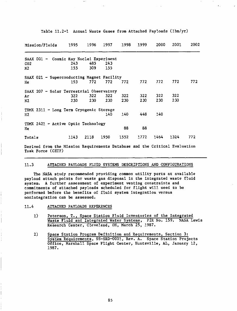
Table 11.2-1 Annual Waste Gases from Attached Payloads (lbm/yr)
Mission/Fluids 1995 1996 1997 1998 1999 2000 2001 2002
SAAX 001 - c02 243 485 243 N2 15 5 309 155
Cosmic Ray Nuclei Experiment
SAAX 021 - Superconducting Magnet F a c i l i t y He 193 772 772 772 772 772 772 77 2
SAAX 207 - Solar Terrestrial Observatory A r 322 322 322 322 322 322 322 N2 2 30 230 230 230 230 230 230
TDMX 2311 - Long Term Cryogenic Storage H2 140 140 448 140
TDMX 2421 - Active Optic Technology He 88 88
To ta l s 1143 2118 1950 1552 1772 1464 1324 772
Derived from the Mission Requirements Database and the Crit ical Evaluat ion Task Force (CETF)
11.3 ATTACHED PAYLOADS FLUID SYSTEMS DESCRIPTIONS AND CONFIGURATIONS
The NASA study recommended providing common u t i l i t y p o r t s a t ava i l ab le payload a t t a c h po in t s f o r waste gas d i sposa l i n the in t eg ra t ed waste f l u i d system. commitments of a t tached payloads scheduled f o r f l i g h t w i l l need t o be performed before the b e n e f i t s of f l u i d system i n t e g r a t i o n versus nonin tegra t ion can be assessed.
A f u r t h e r assessment of experiment vent ing c o n s t r a i n t s and
11.4 ATTACHED PAYLOADS REFERENCES
1) Peterson, T., Space S t a t i o n F lu id Inven to r i e s of t he In t eg ra t ed Waste Fluid and In tegra ted Water Systems, P I R No. 159. NASA L e w i s Research Center, Cleveland, OH, March 2 5 , 1987.
2) Space S t a t i o n Program Def in i t i on and Requirements, Sec t ion 3: System Requirements, SS-SRD-0001, Rev. A. Space S t a t i o n P r o j e c t s Off ice , Marshall Space F l i g h t Center, Huntsv i l le , AL, January 12, 1987.
85
12.0 FLUID SERVICER/VEHICLE ACCOMMODATIONS
The Space S t a t i o n long range goals include the r e p a i r and se rv ic ing of var ious space based s a t e l l i t e s and platforms. r equ i r e s the use of t r anspor t vehic les such as the O r b i t a l Maneuvering Vehicle (OW), the O r b i t a l Transfer Vehicle (OTV) o r the Manned Maneuvering Unit (MMU) t o t r anspor t sa te l l i t es and platforms t o and from the Space S t a t i o n (SS) f o r r e p a i r o r re fue l ing . To r e f u e l a spacec ra f t on-orbit w i l l r equ i r e the use of the mono-propellant vers ion of Orb i t a l Spacecraf t consumables resupply sys tem (OSCRS) f o r hydrazine users o r t he Superf luid Helium Tanker (SFHT) f o r resupply of Superf luid Helium (SFHe).
To accomplish t h i s goal
12.1 FLUID SERVICER/VEHICLE ACCOMMODATIONS OVERALL REQUIREMENTS
The top level requirements f o r f l u i d serviced vehic le accommodations are t o provide f o r pos t I O C Space S t a t i o n use of a Nat ional Space Transpor ta t ion System (NSTS) s h u t t l e based system which w i l l be t ranspor ted aboard the s h u t t l e t o and from Space S t a t i o n and re fue led and serviced on the ground. This w i l l r equ i r e pro tec ted s torage with power, communications, d a t a management and s t r u c t u r a l i n t e r f aces .
12.2 FLUID SERVICER/VEHICLE ACCOMMODATIONS FLUID SYSTEMS REQUIREMENTS
There are no f l u i d subsystem requirements f o r I O C SS with regard t o f l u i d s e r v i c e r s o r vehicles . The only f l u i d requirements a t I O C a r e f o r s c a r r i n g of the In tegra ted Nitrogen System f o r growth t o support a low and high pressure po r t f o r a se rv ic ing f a c i l i t y and high pressure p o r t s f o r t he OW, an Enhanced Maneuvering Unit (EMU) and an Extra vehicu lar Excursion Unit (EEV).
12.3 FLUID SERVICER/VEHICLE ACCOMMODATIONS FLUID SYSTEMS DESCRIPTIONS AND CONFIGURATIONS
12.3.1 O r b i t a l Maneuvering Vehicle Descr ipt ion and Configuration
The OMV conf igura t ion and desc r ip t ion are covered i n d e t a i l i n the Space S t a t i o n Archi tec ture Propel lan t System Databook, EP 1.1.
12.3.2 Orb i t a l Transfer Vehicle (OTV) Descr ipt ion and Configurat ion
The OTV conf igura t ion and desc r ip t ion a r e covered i n d e t a i l i n the Space S t a t i o n Archi tec ture Propel lan t System Databook, EP 1.1.
12.3.3 Manned Maneuvering Unit (MMU) Descr ipt ion and Configuration
The MMU conf igura t ion and desc r ip t ion are covered i n d e t a i l i n the Space S t a t i o n Archi tec ture Propel lan t System Databook, EP 1.1.
12.3.4 O r b i t a l Spacecraf t Consumables Resupply System (OSCRS) DescriDtions and Confinurat ions
The OSCRS conf igura t ion and desc r ip t ions are covered i n d e t a i l i n the Space S t a t i o n Archi tec ture Propel lan t System Databook, EP 1.1
86

12.3.5
12.3.5.1 SFHT General Descr ip t ion
Superf luid Helium Tanker (SFHT) Descr ipt ion and Configuration
I n i t i a l l y resupply w i l l be accomplished as a S h u t t l e based operation. A t y p i c a l resupply opera t ion would use the SFHT mounted t o a p a l l e t i n the Shu t t l e Cargo Bay, once on o r b i t , t he user s a t e l l i t e w i l l be safed by S a t e l l i t e RF Control , and appendages configured f o r r e t r i e v a l with the o r b i t e r Remote Manipulator System (RMS). The RMS w i l l p lace the s a t e l l i t e on the SFHT berthing equipment, where it w i l l be secured with l a t ches . umbil icals are i n s t a l l e d and v e r i f i e d t o be func t iona l , t he Extra vehicu lar Ac t iv i ty (EVA) crew is no longer required f o r chilldown of Super Fluid Helium (SFHe) t r ans fe r . F lu id t r a n s f e r is then con t ro l l ed by a mission s p e c i a l i s t from the A f t F l igh t Deck (AFD) Control Panels. use of SFHT on an OMV. System requirements f o r t he SFHT a r e shown i n Table 12.3-1.
Af te r the
Future growth would ca l l f o r
Table 12.3-1 Primary Superf luid Helium Tanker Requirements
Provide the v e r s a t i l i t y t o s a t i s f y NASA requirements f o r resupply of SFHe t o a v a r i e t y of users f o r i n i t i a l design cons idera t ions SIRTF resupply shall be considered the design basel ine.
Provide an adaptable and v e r s a t i l e SFHT design that can meet the requirements f o r o r b i t a l resupply of SFHe i n t o the next century without major hardware modif icat ions.
Meet hold times of fou r weeks on the ground and nine months on o r b i t .
Designed f o r low c o s t maintenance by using ground based check-out, maintenance, overhaul and adjustment.
Designed t o be compatible with use on an OMV.
Operating L i f e ; 50 Cycles
Useful L i f e ; 20 Years
Shelf L i f e ; 20 Years
Withstand surges from zero pressure t o peak surge pressure and r e t u r n t o Maximum Expected Operating Pressure (MEOP) wi th in 20 miliseconds . Safe ty redundancy s h a l l s a t i s f y NHB 1700.7A (Two-fault to le rance t o a hazard).
No c red ib l e s i n g l e f a i lu re s h a l l r e s u l t i n permanent i n a b i l i t y of SFHT t o complete mission. (One-fault to le rance t o mission success)
Conform t o Orb i t e r Payload bay envelope.
87
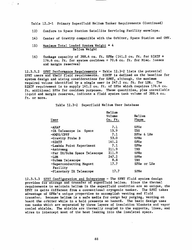
Table 12.3-1 Primary Superf luid Helium Tanker Requirements (Continued)
13) Conform t o Space S t a t i o n S a t e l l i t e Servicing F a c i l i t y envelope.
14) Center of Gravi ty compatible with the Orb i t e r , Space S t a t i o n and OMV.
15) Maximum To ta l Loaded System Weight = 4 Helium Weight
16) Tankage capac i ty of 388.4 CU. f t . SFHe (141.2 CU. f t . f o r SIRTF + 176.6 cu. f t . f o r system cooldown + 70.6 CU. f t . f o r Misc. l o s s e s and margin reserves)
12.3.5.2 SFHT use r s and t h e i r f l u i d requirements. system design and s i z i n g cons idera t ions f o r SFHT, although, t he maximum required volume i d e n t i f i e d by a s i n g l e use r i s 247.2 cu. f t . f o r LDR. SIRTF requirement is t o supply 141.2 cu. f t . of SFHe which r equ i r e s 176.6 cu. f t . add i t iona l SFHe f o r cooldown purposes. These q u a n t i t i e s , p lus unavai lable l i q u i d and margin reserves , i nd ica t e a f l u i d system tank volume of 388.4 cu. f t . o r more.
SFHT Performance Requirements - Table 12.3-2 l i s ts the p o t e n t i a l SIRTF i s def ined as the base l ine f o r
The
Table 12.3-2 Superf luid Helium User Database
User
-AXAF -1R Telescope i n Space -MMPS/CPPF -Gravi ty Probe B -SERTF -Lambda Point Experiment -As t r omag -Far IR/Subm Space Telescope
-Submm Telescope -Superconducting Magnet
-Planetary I R Telescope
-
-LDR
F a c i l i t y
H e l i u m Volume CU. F t .
7.1 15.9
7.1 53.0
141.2 7.1
211.9 211.9 247.2
8.8 17.7
17.7
Helium Phase
SFHe TBS SFHe & LHe S FHe SFHe SFHe TBD SFHe SFHe TB S SFHe o r LHe
S FHe
12.3.5.3 SFHT Configuration and Subsystems - The SFHT f l u i d system design provides f o r s to rage and t r a n s f e r of super f lu id helium. Since the thermal requirements t o maintain helium i n the super f lu id condi t ion are so unique, the SFHT is q u i t e d i f f e r e n t from a conventional cryogenic tanker. The SFHT t akes advantage of SFHe's unique p rope r t i e s t o accomplish vent ing and f l u i d t r ans fe r . Because helium is a safe media f o r cargo bay purging, vent ing on board the o r b i t e r while i n a hold presents no hazard. The bas ic design uses two tanks which a r e separated by th ree l aye r s of i n s u l a t i o n blankets and vapor cooled sh ie lds . The s h i e l d s are thermally coupled t o the suppor ts , l i n e s , and wires t o i n t e r c e p t most of the hea t leaking i n t o the in su la t ed space.
88
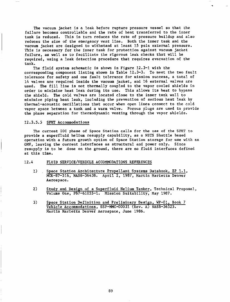
The vacuum jacke t is a leak before rupture pressure vesse l so t h a t the f a i l u r e becomes c o n t r o l l a b l e and the r a t e of hea t t r ans fe r r ed t o the inner tank is reduced. This i n t u r n reduces the rate of pressure buildup and a l s o reduces t h e s i z e of the emergency vent l i n e . Both the inner tank and the vacuum jacke t are designed t o withstand a t least 15 p s i a ex te rna l pressure. This is necessary f o r t he inne r tank f o r p ro tec t ion aga ins t vacuum jacke t f a i l u r e , as w e l l as t o f a c i l i t a t e t he r igorous leak checks t h a t w i l l be required, using a l eak de tec t ion procedure that r equ i r e s evacuation of the tank.
The f l u i d system schematic is shown i n Figure 12.3-1 with the corresponding component l i s t i n g shown i n Table 12.3-3. to le rance f o r s a f e t y and one f a u l t to le rance f o r mission success, a t o t a l of 14 valves are requi red i n s i d e the vacuum jacke t , and 16 ex te rna l valves a r e used. The f i l l l i n e i s not thermally coupled t o the vapor cooled s h i e l d s i n order t o minimize hea t l eak during i ts use. This a l lows i ts hea t t o bypass the sh ie ld . The cold va lves a r e loca ted c lose t o the inner tank wall t o minimize piping hea t leak , including the prevent ion of s e r ious hea t l eak by thermal-acoustic o s c i l l a t i o n s t h a t occur when open l i n e s connect t o the cold vapor space between a tank and a w a r m valve. Porous plugs a r e used t o provide the phase sepa ra t ion f o r thermodynamic vent ing through the vapor sh i e lds .
To meet the two f a u l t
12.3.5.5 SFHT Accommodations
The cu r ren t I O C phase of Space S t a t i o n calls f o r the use of the SFHT t o provide a supe r f lu id helium resupply c a p a b i l i t y , as a NSTS S h u t t l e based opera t ion wi th a f u t u r e growth opt ion of Space S t a t i o n s torage f o r use with an OMV, leaving the cu r ren t i n t e r f a c e s as s t r u c t u r a l and power only. Since resupply is t o be a t t h i s time.
done on the ground, t he re are no f l u i d i n t e r f a c e s def ined
12.4 FLUID SERVICE/VEHICLE ACCOMMODATIONS REFERENCES
1) . Space S t a t i o n Archi tec ture Propel lan t Systems Databook, EP 1.1, MCR-87-516, NAS8-36438. A p r i l 2, 1987, Martin Marietta Denver Aerospace.
2) Study and Design of a Superf luid Helium Tanker, Technical Proposal , Volume One, P87-61055-1. Mission S u i t a b i l i t y , May 1987.
3) Space S t a t i o n Def in i t i on and Prel iminary Design, WP-01, Book 7 Vehicle Accommodations, SSP-MMC-00031 (Rev. A) NAS8-36525. Martin Marietta Denver Aerospace, June 1986.
89
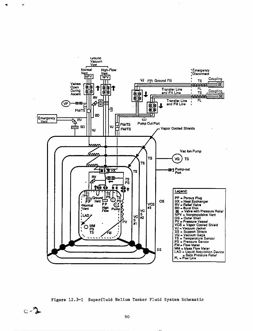
cirouna Vacuum Vent
ial I
VJ
No
F W S
Emergency LyMt. 1-
I
'low I
;Emergency ,Disconnect
I' 3
I7 I l l LlJ
'C i 2
1
- Vapor Cooled Shields
Vac bn Pump
-@ TS
-1 Pumpout Poct
os
is
Legend
PP - Porous Plug HX - Heat Exchanger RV - Relief Valve BO - Burst Disk I - Valve with Pressure Relief NPV Nonpropulsive Vent OS - Outer Shell PV - Pressure Vessel VCS - Vapor Cooled Shield VJ - Vacuum Jacket SS - Support Straps VG - Vacuum Gage TS - Temperature Sensor PS - Pressure Sensor FM - Fbw Meter MM - Mass Flow Meter LAD - Liquid Acquisition Device - Back Pressure Relief FL - Flex Line
Figure 12.3-1 Superf lu id Helium Tanker F l u i d System Schematic
90

I
91