The Cushcraft ASL 2010 Log-PeriodicAntenna - … · CQ REVIEWS: The Cushcraft ASL 2010...
4
CQ REVIEWS: The Cushcraft ASL 2010 Log-Periodic Antenna BY PAUL CARR ' , N4PC The completed antenna ready 10 take on Ihe world. Is anyone listening? W ell, spring vacation finally came. and It was a welcome renet trom my classroom du- ties, I had been looking forward to this break because it would give me a chance to assem- ble and build a new an tenna. Wa iti ng in my garage was the new Cusncratt ASL 20 10 log- peri od ic system. Since then I have had lime to evaluate the system. Here are the results oft hat evaluation. What Is A Log-Periodic Antenna? A log-periodic antenna is a treqoercv-moe- pendent antenna system. These antennas are capable of bandwidths that were impossible a few years ago. This particular system has a 2: 1 bandwidth of better than two octaves. This is accomplished bythe choice of element length, spacing. and phasing.(All of the elements are fed simultaneously.) The element lengths vary from slightly greater than a half-wave length at the lowest frequency to just less than a half- wave length at the highest frequency. The re- sulting gain is about constant, and the nomi- nal impedance IS about 200 ohms. By using a 4:1 bahJn an impedance of approximately 50 ohms results. Now for a few specifics about cusncratrs design. The ASL 2010 M echani ca lly, the speci fications for the beam area boom lengtho 118 feet, wit ha boom diameter of 2 inches. The longest el ement is 38 feet. and the turning radi us is 19.25 feet. The be am ac cepts a mas t diameter of 1. 5- 2 inches, a nd the total weight is 55 pou nds. The wi nd load ing 10. 1square feet All the hardware is of the highest quality stainless steel, whiCh we have come to expect from Cushcraft. Assembly As you can see from the picture, the antenna The ASl20 10 is a new product from Cus hcratt, and it covers 20, 17, 15, 12, and 10 meters. The antenna consists of eight elements in a log-periodic dipole array. The antenna is fed through a single 50 ohm coaxial cable to a 4: 1 balun matching unit (mounted on the boom). The beam IS rated at 2000 wans. The electrical 2:1 bandwidth of the antenna as specified by Cushcrafl is from 13.5 MHz to 32 MHz. As I indicated earlier, this is a prop- erty of the log-periodic design. I used an MFJ 259 to make SWR measurements across the spectrum and on each of the ama teur bands. Never did the SWA e xcee d 2:1 a cr oss the spectrum. The most variation in SWR occurred on 20 meters. The maximum SWR of 1.7:1was at 14.0 MHz, and the minimum of 1.3:1 was at 14.25MHz. TheSWRresultson 10 meters were amazingly flat. never exceeding 1.4:1 across the entire band (see fig. 1). The published gain figure lor the antenna is 6.4 dBd It is extremely difficult to verily gain ligures withOut acalibrated antenna range, but comparing the results I received with other an- tennas, I feel the gain figure is about right. The rated front-to-back ratio is stated to be 15- 20 dB. I found no place throughout the spect rum where I t en this information was in accurate. "91 West Point Road, Jacksonville, AL 36265 26 • CO • August 1995 As you can see, there afe enough paris here to keep you busy for ar reasr a day. Please note thatlhe flower pots ere not included. Say You Saw It In CO
-
Upload
nguyenminh -
Category
Documents
-
view
273 -
download
3
Transcript of The Cushcraft ASL 2010 Log-PeriodicAntenna - … · CQ REVIEWS: The Cushcraft ASL 2010...

CQ REVIEWS:
The Cushcraft ASL 2010Log-Periodic Antenna
BY PAUL CARR ' , N4PC
The completed antenna ready 10 take on Ihe world. Is anyone listening?
W ell, spring vacation finally came. and Itwas a welcome renet trom my classroom duties, I had been looking forward to this breakbecause it would give me a chance to assemb le and build a new antenna. Waiting in mygarage was the new Cusncrat t ASL 20 10 logper iodic system. Since then I have had lime toevaluate the system.Here are the resultsofthatevaluation.
What Is ALog-Periodic Antenna?
A log-periodic antenna is a treqoercv-moependent antenna system. These antennas arecapable of bandwidths that were impossible afew years ago. This particular system has a 2:1bandwidth of better than two octaves. This isaccomplished by the choice of element length,spacing. and phasing . (All of the elements arefed simultaneously.) The element lengths varyfrom slightly greater than a half-wave length atthe lowest frequency to just less than a halfwave length at the highest frequency. The resulting gain is about constant, and the nominal impedance IS about 200 ohms. By using a4:1 bahJn an impedance of approximately 50ohms results. Now for a few specifics aboutcusncratrs design.
The ASL 2010
Mechanically , the specifications for thebeam area boom lengtho118 feet, witha boomdiameter of 2 inches. The longest element is38 feet. and the turning radius is 19.25 feet.The beam accepts a mast diameter of 1.5-2inches, and the total weight is 55 pounds. Thewind load ing 10. 1square feet All the hardware
is of the highest quality stainless steel, whiChwe have come to expect from Cushcraft.
Assembly
As you can see from the pic ture, the antenna
The ASl2010 is a new product from Cushcratt,and it covers 20, 17, 15, 12, and 10 meters.The antenna consists of eight elements in alog-periodic dipole array. The antenna is fedthrough a single 50 ohm coaxial cable to a 4: 1balun matching unit (mounted on the boom).The beam IS rated at 2000 wans.
The electrical 2:1 bandwidth of the antennaas specified by Cushcrafl is from 13.5 MHz to32 MHz. As I indicated earlier, this is a property of the log-periodic design. I used an MFJ259 to make SWR measurements across thespectrum and on each of the amateur bands.Never did the SWA exceed 2: 1 across thespectrum. The most variat ion in SWRoccurredon 20 meters. The maximum SWR of 1.7:1wasat 14.0 MHz, and the minimum of 1.3:1 was at14.25MHz. TheSWRresultson 10meters wereamazingly flat. never exceeding 1.4:1 acrossthe entire band (see fig. 1).
The published gain figure lor the antenna is6.4 dBd It is extremely difficult to verily gainligures withOut acalibrated antenna range, butcomparing the results I received with other antennas, I feel the gain figure is about right. Therated front- to-back ratio is stated to be 15- 20dB. I fou nd no place throughout the spectrumwhere I ten this information was inaccurate.
"91 West Point Road, Jacksonville, AL 36265
26 • CO • August 1995
As you can see, there afe enough paris here to keep you busy for ar reasr a day. Please notethatlhe flower pots ere not included.
Say You Saw It In CO

Th ings will go easier and faster if you can coerce some ttienas into helping you out. Here Ralph,KE4UAK, puts the finishing touches on some connections. while Harold. W4ZS, supervises
the handiwork
has a very high parts count. Your success depends on you r ability to do an accurate inventory of the parts and organize the parts fo r easyaccessibility during the construction phase. Ifyou are working alone dur ing the initial co nstruction phase, allow about one davto assemble the elements and the boom.
There are seven steps listed in the instruction manual. Assemble the boom first. This willg ive you practice working with hand tools andwill ie! you become used to the way the instructio ns are written. The boom is in three sec tions ,with the end sections made so they will slip intothe center section fo r a predetermined leng thand then slop. All that is necessary is to p lacetwo locking screws and l ighten the compression hose clamps. Place the plastic end covers, and you are finished .
The element construction is next. Begin withthe longest element. Carefu lly measure theoverlap specified on the d iagram. The total e lement length is dependent on the proper measurement and assembly of the elements . Contin ue the element construct ion as specified inthe instruction sheet. Verify the element lengthsat least twice.
Now you have a decision to make. If youintend to fully assemble the antenna be fore youplace it on the mast, follow the instructions inthe booklet. I have a crank-down/t ilt-over tower , and I chose to depart from the instruc tions.Following is how to accomplish the installation.
Carefully measure and mark the location ofeach element and the boom-to-mast bracket.Next mount the boom-to-mast bracket. Thenmove all the assembly components tome mast
location. Turn the antenna rotor so that it w illdi splay the proper d irection when the tower isti lted to allow installation. Moun t the boom tothe mast, verify a ll the steps, and tighten themo unting hardware .
Moun t the longest e lement, and check forproper alignment. Follow by p lacing the nexttwo longest e lements. After yo u are satisfiedthat the elements are in the proper position.place the phasing straps in accordance with
2.0
Fig.
a:~ 15<f>
1- These are the SWR curves for each band as I derived themfrom my OTH.
1.514.514.414.2 14.3Frequency
1.0':-::----;-:'-:----;-!-;:---,-!-::---:+::--.,.f;~14.0 14.1
(A) 20 METERS
20 24.94 24.99 25.04Frequency
25.09 25.14
(0) 12 METERS
a:~ 1.5
1.0 2.018.069 18.118 18.168 19.068 19.11 8 20.068Frequency
(B) 17 METERS0:~ 1.5
1.5 en0:~en 1.0
1.0 28.0 28.5 29.0 29.5 30.0 30.521.0 21.1 21.2 21.3 21 .4 21.5 Frequency
Frequency (E) 10 METERS(C) 15 METERS
28 • CO • August 1995 Say You Saw It In CQ
AUQust 1995 • CO • 29
3" (7.6 em)
I - 38' .. '(11,58 m) I
~ IT~
ff I , k ! . • • .
I Be "46-318"
117.8 cm)
33'-3.5" ,If2\
(10.15 m).
38"(96,5 em)
28'-3,25" ,I(8.62 m)
3 • .
16-1 ;2" -(41.9 em)
M:~33"(83.8 em)
24'-3.5" "I4'
(7.4 m)
28-112"(72.4 eml
I 20'·11.5" -Il'f\ =@
(6.39 ml
24·518"(62.5 em)
' I: I 18'-3.5"(5.57 m]
~~I.
21-1/4"(54 em) -I~
16'·2,75"(4.95 m)
7[ 3" (78,ml
18-1/4"(46.4 em)
1
1 13'-10.5",(4.23 m\_I 8 ""it.
f
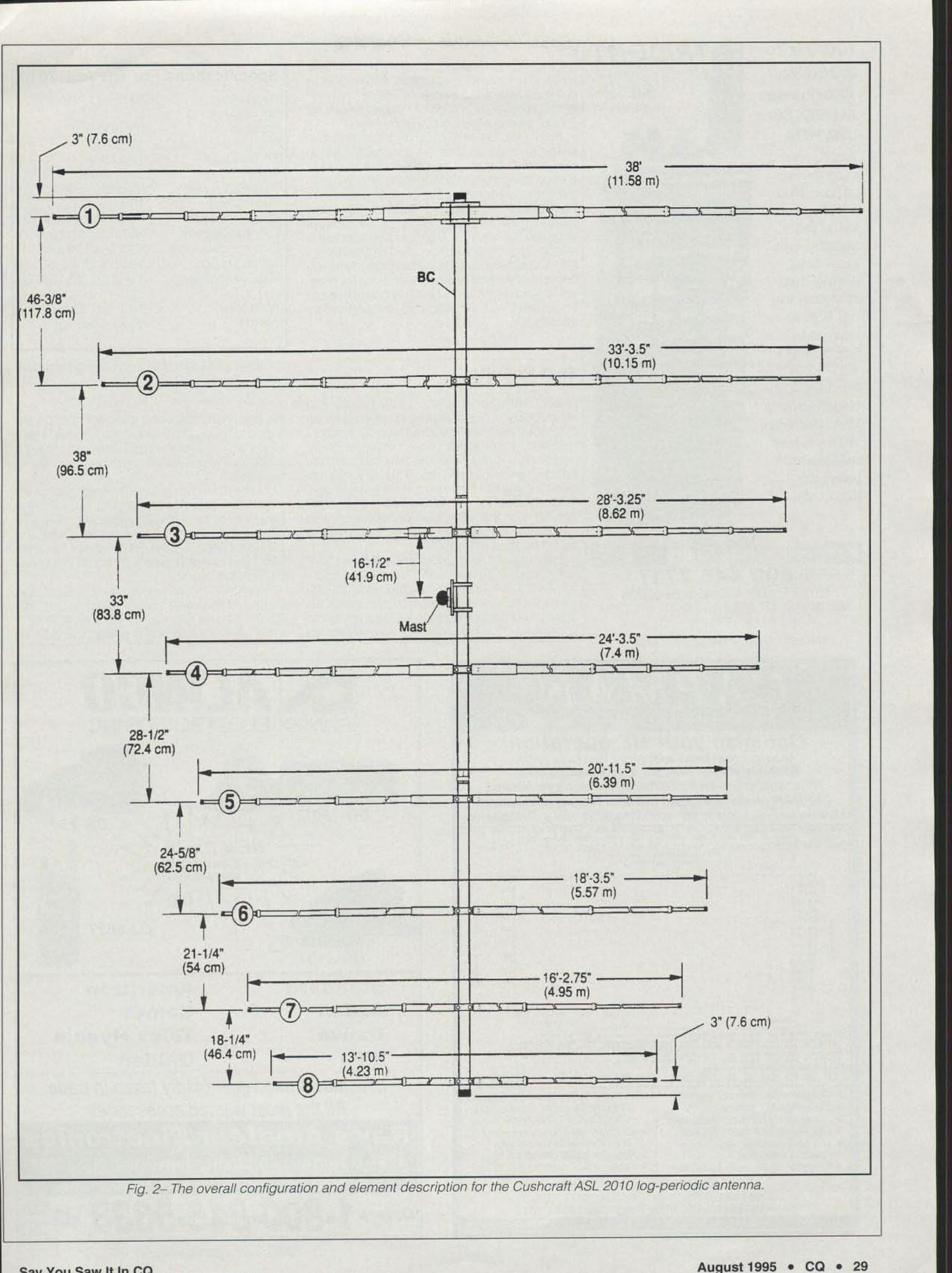
Fig.2 The overall configuration and element description for the Cushcraft ASL 2010 log-periodic antenna.
0::. .. .. v ..... c:. .. ,.. I t I ... rn

ORClE 2\ ON READER SERVICE CAFlO
13,5-32 MHz86.4 dBd15-20 dB18 ,5MHz2000 watts65 deg E plane18 ft , (5.48 m)2.0 in. (5.08 cm)as n. (11.58 m)1.25 in,(3.18cm}19.25 ft, (5.86 m )1.5-2 in. (3.18-5.08
10.1 tt.2 (,93 m2)55 lb . (25.5 kg)
FrequencyNo, of elementsForward gainFront-to-bec k ratio2:1 BandwidthPower rating3 dB Beam widthBoom lengthBoom diameterLongest elementElement center ceTurning rad iusMast size rangeem)Wind loadWeight
the antenna under such ccooncos. and I amhappy10 report that the antenna handled thesewinds with no problems, II I were describing asailboat, I would report that she rides well inthe water ,
If I may insert an aesthetic observation, I ama mathematician by protession, and I find thegeometry to be espec ially pleasing . My XYLshares my opinion. She remarked that shettlOught it was the prettiest antenna I had everhad . and she has seen plenty of antennasthrough the years!
The ASL2010 is maoutactueeo by CusncrattCorp , 48 Perimeter Road. Manchester, NH03108 (phone 603-627-7877; FAX 603-6271764). The retail price of the ASL 2010 is S8OO,
TabJe I-ASL 20 10 anfenna specIfications,
Specifications For The ASL 2010the instruction booklet. You now should havethree elements in place. and phasing linesbetween two of the elements. Raise the mastto the vertical posi tion and visually check lorproper eerreor-to-toon alignment.
Rotale the assembly 180 degrees. and lower the antenna so that the assembly can becompleted Continue by plac ing the elementsand phasing lines in a longest to shortest pattern untillhe antenna is completely assembled.Recheck allhardwareand elements, Mount thematching network and connect the networkoutpu t to the antenna. Connect the coax to thematc hing network (be sure to leave a drip loop )and route the coax to the shack. Raise the antenna to its vertical position and check for proper element alignment. Make any corrections asnecessary , You are now ready for preliminarytests.
Test Results
I have made many tests on auue bands. andalthough band conditions have been less thandesirable. I am we ll pleased with all results Ireceived. I feel the antenna performs great.and a plus is the fact that you have instantband-change capabilities. This is a definitebe nefit if you are interested in multi-band contests such as the CO World-Wide. For an allaround ante nna with good pe rformance andmaximum flexibil ity, I fee l that this antennawould be hard to beat
Iwould like to add a word about the mechanical stability of the beam. In my part of mecountry we do not expe rience great straight-linewinds that are seen other places: however, wedo experience tremendous rotat ing winds associated with thunderstorms. I have observed
TRID&NT_"""$449-
100KHz to2.06GHz,1CXXJ CIaW19IsAA(IFJWl.SB{USB{WFMTootl coYl.'fage al
a very economical pice. BAJ& VRJ, Searchlockout andSignal Strengjhmeter. Steps<kNm to IKHz.EEPROM memcry, BNC antennacoerecccSize: 5 7~r1 x I1I2'D x 'lW.we 140z.. CeUbocsed flY usc inUSA Call <K faxToll free in USA
am Canada. 24hour.; a day, 7days a week.
-ACE-C!C COMiO~A'~ III~1 800 445 7717
10707 E. 106th. FIShers. IN 46038IntematJonal: 317 642 7115 Fax 317 849 8794
AmeritronCometTelex Hygain
iOR-130
~~ NEW OX·TO .. HF + 6 Meters With
7i~~-;'\'-:OJ-582T
C\.AL'NCO"'LlNCD RECTRONICS INC.
StandardAzdenDaiwaMFJ Uniden
•
•I
I•
-•.., ..
\ ,~'
\~•• <••
•
" .• ••• • < <
_..b--r--rr-t-r-'-r-....,••• 'a..;--.,;.,.-;"• ...., >...,.-1......" .." ,, ~ ..
M .M .
o .••d .
0_.
I........
• .0 •0 •••
o.0
••••
..,. ....4 - _ 01 14. ,. .,_ . ... _ - , • • ,,_, .. _ , •_ •. ,DD _• • _ _ Ie • _, • • It _ . _ ..
Ito , _.~ U _ uo _ _ ,_. " ' l ..._ . F. ~ " ...
...,.,-"- .-" .. .. . . . . . .. .. .. .. ..
Optimize your HF operation!Know /he bes t time s end bends for skeds or OX,Eve/uete ,'e!fon cheng.. D'foct makIng them.
WIN a blg(JfJr amp do the job ? Whs/ about changing the antenna?
CAPMAN provides answ91'5 In a user friendly menu drtven~.... -,",/)'sIs padcage wffh OOIItuf-..n8ltNe heJp Ii colorgtllphlcs
Late model used gear gladly taken in tradeAll the most wanted accessories
Ray's Amateur Electronics1701-G North Main Street, High Point, NC 27262
Local 910-883-6038 FAX 910-883·1464
iorders 1·800·845·5338 ~~iCIRCLE 90 ON READER SERVICE CARD
30 .. CO .. AUQust 1995 Cl.... v",,, (l ..... ,<._,.,...