Thank you for purchasing Kipor KD388、KD488 series … · Thank you for purchasing Kipor KM2V80...
54
Thank you for purchasing Kipor KM2V80 series diesel engine. In order to ensure proper operation, reliable running and good economic benefit of your machine, it is especially important for you to operate correctly and maintain carefully. This manual will tell you how to operate and maintain the machine correctly, it will also give you detail instruction about the main technical specification, configuration and troubleshooting. Content Instruction of products……………………………………………………………………………..1 1. Brief instruction of products……………………………………………………………....1 2. Composition of model and its meaning………………….………………………………1 3. External installation drawings and names of parts……………………………………. 2 4. Specification………………………………………………………………………………. 6 5. Main adjusting parameter………………………………………………………………… 7 6. Tighten torque values of main bolts and nuts……………………………………………7 7. Fit clearance and interference table………………………………………………………8 Technical maintenance………………………………………………………………………………9 1. Daily check and periodic check …………………………………………………….9 2. Procedure of periodic maintenance………………………………………………………..9 Disassembly and reassembly…………………………………………………………………….. 13 1. Basic procedure of disassembly…………………………………………………………..13 2. Basic procedure of reassembly……………………………………………………………18 Check and maintenance……………………………………………………………………………22 1. Cylinder cover…………………………………………………………………………….. 22 2. Camshaft...............................………………………………………………………………23 3. Piston and piston pin……………………………………………………………………… 24 4. Crankshaft………………………………………………………………………………… 25 5. Cylinder block and cylinder cover ................................................................................ 6. Lubrication system……………………………………………………………………….. 27 7. Cooling system…………………………………………………………………………… 27 8. Fuel system……………………………………………………………………………… 28 The electrical system…………………………………………………………………………… 29 1. Starter motor……………………………………………………………………………… 29 2. Heater plug............…………………………………………………………………… .31 Troubleshooting and remedy of engine………………………………………………………...35 Preliminary run...........................................................................................................….........39
Transcript of Thank you for purchasing Kipor KD388、KD488 series … · Thank you for purchasing Kipor KM2V80...

Thank you for purchasing Kipor KM2V80 series diesel engine. In order to ensure proper
operation, reliable running and good economic benefit of your machine, it is especially important
for you to operate correctly and maintain carefully. This manual will tell you how to operate and
maintain the machine correctly, it will also give you detail instruction about the main technical
specification, configuration and troubleshooting.
Content
Instruction of products……………………………………………………………………………..1
1. Brief instruction of products……………………………………………………………....1
2. Composition of model and its meaning………………….………………………………1
3. External installation drawings and names of parts……………………………………. 2
4. Specification………………………………………………………………………………. 6
5. Main adjusting parameter………………………………………………………………… 7
6. Tighten torque values of main bolts and nuts……………………………………………7
7. Fit clearance and interference table………………………………………………………8
Technical maintenance………………………………………………………………………………9
1. Daily check and periodic check …………………………………………………….9
2. Procedure of periodic maintenance………………………………………………………..9
Disassembly and reassembly…………………………………………………………………….. 13
1. Basic procedure of disassembly…………………………………………………………..13
2. Basic procedure of reassembly……………………………………………………………18
Check and maintenance……………………………………………………………………………22
1. Cylinder cover…………………………………………………………………………….. 22
2. Camshaft...............................………………………………………………………………23
3. Piston and piston pin……………………………………………………………………… 24
4. Crankshaft………………………………………………………………………………… 25
5. Cylinder block and cylinder cover................................................................................
6. Lubrication system……………………………………………………………………….. 27
7. Cooling system…………………………………………………………………………… 27
8. Fuel system……………………………………………………………………………… 28
The electrical system…………………………………………………………………………… 29
1. Starter motor……………………………………………………………………………… 29
2. Heater plug............…………………………………………………………………… .31
Troubleshooting and remedy of engine………………………………………………………...35
Preliminary run...........................................................................................................….........39
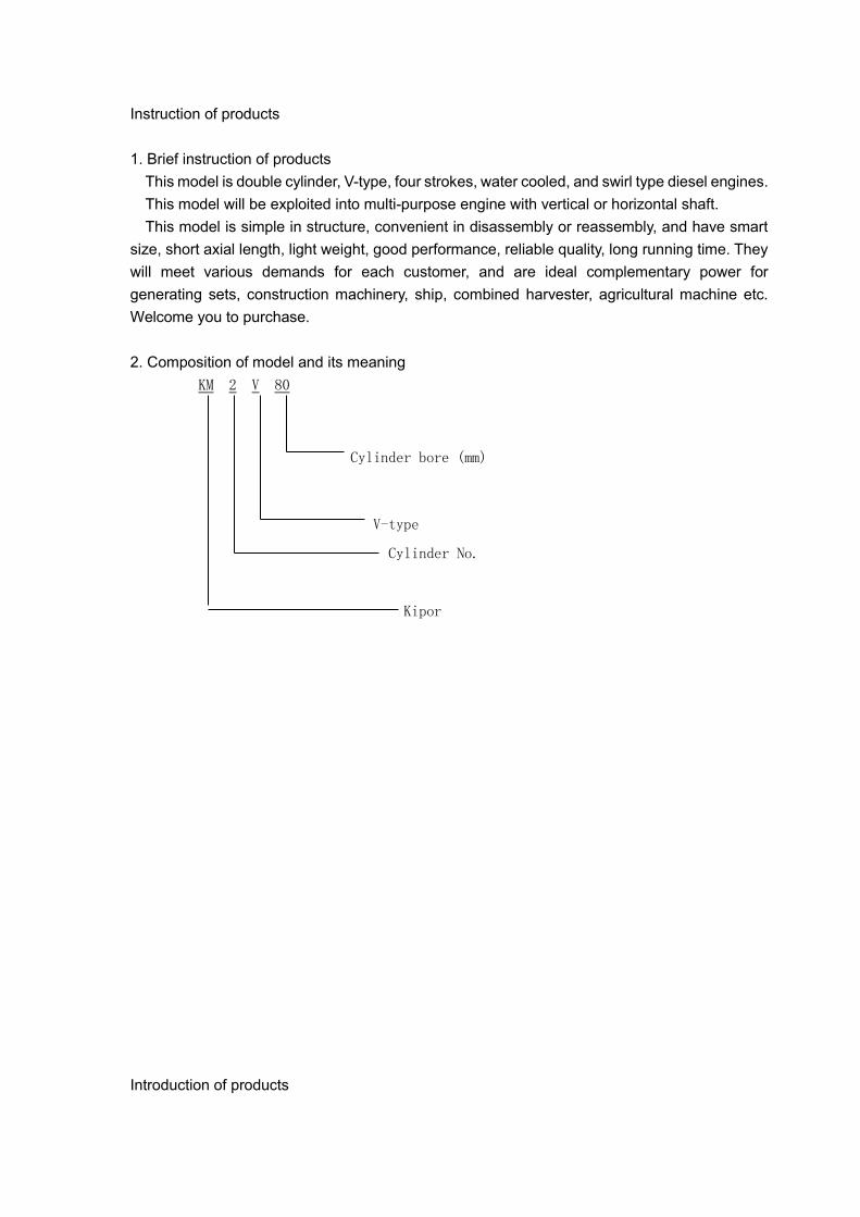
Instruction of products
1. Brief instruction of products
This model is double cylinder, V-type, four strokes, water cooled, and swirl type diesel engines.
This model will be exploited into multi-purpose engine with vertical or horizontal shaft.
This model is simple in structure, convenient in disassembly or reassembly, and have smart
size, short axial length, light weight, good performance, reliable quality, long running time. They
will meet various demands for each customer, and are ideal complementary power for
generating sets, construction machinery, ship, combined harvester, agricultural machine etc.
Welcome you to purchase.
2. Composition of model and its meaning
KM 2 V 80
Cylinder bore (mm)
V-type
Cylinder No.
Kipor
Introduction of products

3. External installation drawings and name of parts
Please refer to picture 1, picture 2, picture 3 and picture 4 for details.
Picture1 Vertical section view for KM2V80 diesel engine

Picture 2 Horizontal section view for KM2V80 diesel engine

Picture 3 Vertical figuration view for KM2V80 diesel engine

Picture 4 Horizontal figuration view for KM2V80 diesel engine

4. Specification
Table 1 Main specification table of KM2V80 diesel engine
Model KM2V80
Type Double cylinder, V-type, water-cooled, 4 stroke,
swirl type
Bore×Stroke mm 80×79
Displacement L 0.794
Compression ratio 23
Rated output/Rated speed
kW/r/min 12.5/3000 14.5/3600
Max. torque N·m 49/1600~1800
Min. speed (zero load) r/min ≤900
Lubricating system Pressure splashed
Starting system Electric starter
Output terminal direction (face
to the flywheel) Anticlockwise
Fuel type 0#(summer), -10# or -20#(winter), -35#(chillness)
Fuel consumption ratio g/(kW·h) 285 297
Lube oil type SAE 10W-30、20W-40 or L-ECD Grade
Lube oil capacity L 2.27
oil consumption ratio g/(kW·h) ≤5
Starting motor capacity V,kW 12V 1.4 kW
Charging generator capacity
(V,A) 12V 20A
Battery capacity (V,AH) 12V 60AH
Overall dimension (L×W×H) mm 616×486×528
Net weight kg 58
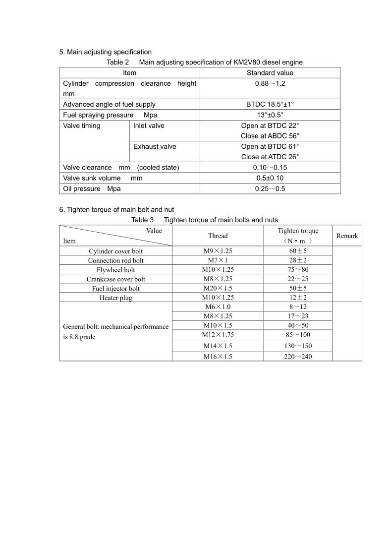
5. Main adjusting specification
Table 2 Main adjusting specification of KM2V80 diesel engine
Item Standard value
Cylinder compression clearance height
mm
0.88~1.2
Advanced angle of fuel supply BTDC 18.5°±1°
Fuel spraying pressure Mpa 13°±0.5°
Valve timing Inlet valve Open at BTDC 22°
Close at ABDC 56°
Exhaust valve Open at BTDC 61°
Close at ATDC 26°
Valve clearance mm (cooled state) 0.10~0.15
Valve sunk volume mm 0.5±0.10
Oil pressure Mpa 0.25~0.5
6. Tighten torque of main bolt and nut
Table 3 Tighten torque of main bolts and nuts
Value
Item Thread
Tighten torque
(N·m ) Remark
Cylinder cover bolt M9×1.25 60±5
Connection rod bolt M7×1 28±2
Flywheel bolt M10×1.25 75~80
Crankcase cover bolt M8×1.25 22~25
Fuel injector bolt M20×1.5 50±5
Heater plug M10×1.25 12±2
General bolt: mechanical performance
is 8.8 grade
M6×1.0 8~12
M8×1.25 17~23
M10×1.5 40~50
M12×1.75 85~100
M14×1.5 130~150
M16×1.5 220~240

7. Fit clearance and interference table
Table 4 Fit clearance and interference table
No. Name Standard dimension(mm) Fitting clearance
(mm) Remark
1 Cylinder inner diameter/
Piston top outer diameter
φ80H7(+0.03
0 )/d-0.515±0.01 0.565~0.635
2 Cylinder inner diameter/
Piston skirt upper part
φ80H7(+0.03
0 )/d-0.125±0.01 0.175~0.245
3 Cylinder inner diameter/
Piston skirt diameter
φ80H7(+0.03
0 )/φ80-0.06
-0.08 0.06~0.110
4. Piston pin hole/Piston pin φ20-0.002
-0.008 /φ20 0 -
0.006 0.004~-0.008
5 The width of ring groove /
The height of 1st ring 1.2
+0.060
+0.040 /1.2-0.01
-0.02 0.05~0.08
6 The width of ring groove /
The height of 2nd ring
1.5+0.040
+0.020 /1.5-0.01
-0.02 0.03~0.06
7 The width of ring groove /
The height of 3rd ring
3.0+0.030
+0.010 /3-0.01
-0.02 0.02~0.05
8 Open clearance of 1st ring 0.25~0.35
9 Open clearance of 2nd ring 0.20~0.35
10 Open clearance of 3rd ring 0.15~0.30
11 Connection rod bushing/
Piston pin diameter
φ20+0.025
+0.015 /φ20 0 -
0.006 0.015~0.031
12 Connection rod bush hole diameter/
Connection rod journal φ40
+0.032
0 /φ40f5(-0.025
-0.036) 0.025~0.062
13 Main bearing bushing hole diameter/
Main journal
φ50+0.035
+0.015 /φ50f5(-0.025
-0.036) 0.040~0.071
14 Crankshaft axial clearance 120.7+0.10
0 /108.6+12=120.6 0 -
0.10 0.10~0.30
15 Crankshaft axial open split/
The width of connection rod big head
40+0.25
+0.10/20-0.15
-0.20 ×2=40-0.30
-0.40 0.40~0.65
16
(Crankshaft center line to the tank
top)/(piston + connection rod + crank
radius) 13.01.1935.395.1251.28
03.054.193
0.28~0.60
17 Camshaft hole diameter/
Camshaft journal
φ18H7(+0.018
0 )/φ18e6(-0.032
-0.043) 0.032~0.061
18 Side cover camshaft hoe diameter/
Camshaft journal
φ24H7(+0.021
0 )/φ24f6(-0.040
-0.053) 0.040~0.074
19 Camshaft axial clearance 176.5+0.10
0 /164.1+12.2=176.3±0.05 0.035~0.15
20 Valve tappet hole/
Tappet diameter
φ10H7(+0.015
0 )/φ10e7(-0.025
-0.040) 0.025~0.055
21 Fuel pump tappet hole/
Fuel pump tappet
φ21H7(+0.021 )(
0)/φ21-0.047
-0.080 0.047~0.101
22 Valve pipe/ Inlet valve φ6H7(+0.012
0 )/φ6-0.030
-0.045 0.03~0.057

23 Valve pipe/ Exhaust valve φ6H7(+0.012
0 )/φ6-0.035
-0.050 0.035~0.062
24 Cylinder cover pipe hole/
Valve pipe
φ10H7(+0.015
0 )/φ10+0.055
+0.045 -0.03~-0.055
25 Cylinder cover housing washer hole/
Inlet valve housing washer
φ33.5H7(+0.025
0 )/φ33.5+0.12
+0.09 -0.065~-0.012
26 Cylinder cover housing washer hole/
Exhaust valve housing washer
φ28H7(+0.021
0 )/φ28+0.11
+0.09 -0.069~-0.11
27 Cylinder cover insert/
Combustion chamber insert
φ32.5H7(+0.021
0 )/32.5p6(+0.042
+0.026) -0.005~-0.042
28 Cylinder cover rocker shaft hole/
Rocker shaft diameter
φ12H7(+0.018
0 )/φ12f6(-0.016
-0.027) 0.016~0.045
29 Rocker arm hole/
Rocker shaft diameter
φ12H7(+0.018
0 )/φ12f6(-0.016
-0.027) 0.016~0.045
30 Timing gear hole/
Camshaft journal
φ24H7(+0.021
0 )/φ25s6(+0.048
+0.035) -0.014~-0.048
31 Crankshaft gear hole/
Crankshaft journal
φ50H6(+0.016
0 )/φ50p5(+0.037
+0.026) -0.010~-0.037
32 Flywheel gear ring hole/
Flywheel stop ring
φ214H7(+0.046
0 )/φ214u7(+0.364
+0.258) -0.212~-0.304
33
Connection rod small head hole/
Connection rod bushing outer
diameter
φ22H7(+0.013
0 )/φ22r6(+0.041
+0.028)
-0.015~-0.041
34 Connection rod bolt hole/
Bolt location diameter
φ7.5H7(+0.015
0 )/φ7.5f6(-0.013
-0.022) 0.013~0.037
35 Side cover outer rotor diameter/
Outer rotor diameter
φ41H7(+0.025
0 )/φ41-0.075
-0.115 0.075~0.14
36 Side cover oil pump shaft diameter/
Shaft diameter
φ11H7(+0.018
0 )/φ11f6(-0.016
-0.027) 0.016~0.045
37 Inner/outer rotor hole depth/
Inner/outer rotor axial depth
12+0.08
+0.04/12 0 -
0.020 0.04~0.10

Technical maintenance
1. Daily check and periodic check
Engine’ performance will be deteriorated if the operation condition becomes worse or time
prolongs, such as: fuel and oil consumption increase, exhaust harmful substance increases, or
vibratory and noise increase. Please strengthen the maintenance service of engine, insist on
daily check and periodic maintenance, which will prove efficiency and prevent fault.
Check can be divided into daily check and periodic check.
Daily check: Do daily check before starting engine, and operate it as a rule.
Periodic check: Suggest you make a running diary, writing down results of everyday operation
and check, accumulating total running time. Start your periodic check and maintenance
according to below table (table 5).
Periodic check can be divided into: 50h、250h、500h、1000h、2000h(h: hours)
Time interval of periodic check can be properly advanced or delayed according to the engine’s
purpose, location condition, fuel or lube oil’s quality and other using conditions.
Table 5 Periodic check table of engine
System Checking item Everyday 50h 250h 500h 1000h 2000h
Fuel
Check and refill fuel oil ○
Check for oil leakage ○
Drain out fuel oil ○
Replace the oil filter element ◎
Lube oil
Check and refill lube oil ○
Check for oil leakage ○
Replace lube oil ◎first
time
◎seco
nd time
Replace lube filter element
Cooling
water
Check and refill cooling water ○
Clean radiator element ○
Replace cooling water ◎
Wash and maintain cooling
system
●
Robber
pipe
Replace fuel pipe and cooling
water tube
○ ◎
Operation
system
Speed regulator operation ○
Idle adjust ●
Inlet
system
Clean and replace air cleaner
element
○clean ◎
Electric
parts
Check alarm ○
Check electrolyte and charge
the battery
○
Cylinder
cover
Adjust clearance of
intake/exhaust valve
○first
time
○seco
nd
time
Wear of intake/exhaust valve
sealing ring belt
●
○:check ◎:replace ●:Contact with Kipor
agent
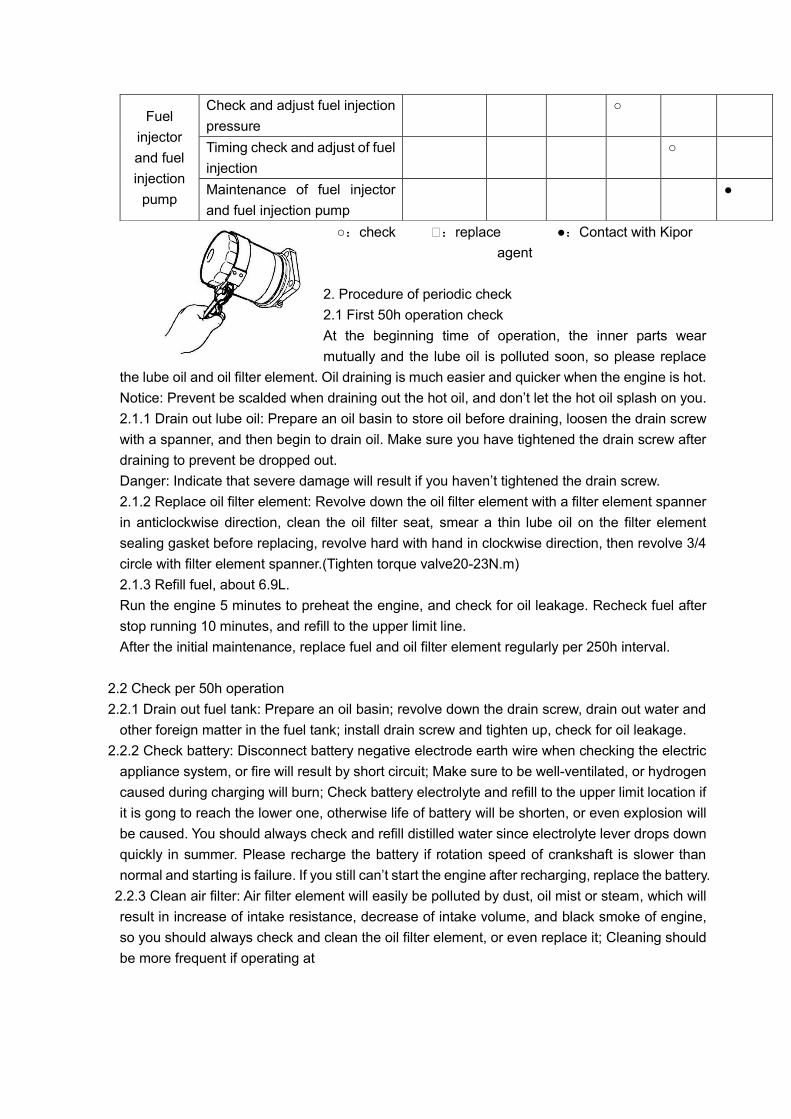
2. Procedure of periodic check
2.1 First 50h operation check
At the beginning time of operation, the inner parts wear
mutually and the lube oil is polluted soon, so please replace
the lube oil and oil filter element. Oil draining is much easier and quicker when the engine is hot.
Notice: Prevent be scalded when draining out the hot oil, and don’t let the hot oil splash on you.
2.1.1 Drain out lube oil: Prepare an oil basin to store oil before draining, loosen the drain screw
with a spanner, and then begin to drain oil. Make sure you have tightened the drain screw after
draining to prevent be dropped out.
Danger: Indicate that severe damage will result if you haven’t tightened the drain screw.
2.1.2 Replace oil filter element: Revolve down the oil filter element with a filter element spanner
in anticlockwise direction, clean the oil filter seat, smear a thin lube oil on the filter element
sealing gasket before replacing, revolve hard with hand in clockwise direction, then revolve 3/4
circle with filter element spanner.(Tighten torque valve20-23N.m)
2.1.3 Refill fuel, about 6.9L.
Run the engine 5 minutes to preheat the engine, and check for oil leakage. Recheck fuel after
stop running 10 minutes, and refill to the upper limit line.
After the initial maintenance, replace fuel and oil filter element regularly per 250h interval.
2.2 Check per 50h operation
2.2.1 Drain out fuel tank: Prepare an oil basin; revolve down the drain screw, drain out water and
other foreign matter in the fuel tank; install drain screw and tighten up, check for oil leakage.
2.2.2 Check battery: Disconnect battery negative electrode earth wire when checking the electric
appliance system, or fire will result by short circuit; Make sure to be well-ventilated, or hydrogen
caused during charging will burn; Check battery electrolyte and refill to the upper limit location if
it is gong to reach the lower one, otherwise life of battery will be shorten, or even explosion will
be caused. You should always check and refill distilled water since electrolyte lever drops down
quickly in summer. Please recharge the battery if rotation speed of crankshaft is slower than
normal and starting is failure. If you still can’t start the engine after recharging, replace the battery.
2.2.3 Clean air filter: Air filter element will easily be polluted by dust, oil mist or steam, which will
result in increase of intake resistance, decrease of intake volume, and black smoke of engine,
so you should always check and clean the oil filter element, or even replace it; Cleaning should
be more frequent if operating at
Fuel
injector
and fuel
injection
pump
Check and adjust fuel injection
pressure
○
Timing check and adjust of fuel
injection
○
Maintenance of fuel injector
and fuel injection pump
●

Picture 6 Clean air filter places full of dust(such as quarrying plant, coal yard
or road building plant), foreign matter inside the oil filter should be cleaned; Take out filter
element parts from air filter shell, blow dust down with compression air. Please replace filter
element parts if papery filter element is broken. Clean oil sludge inside the air filter; cover the air
inlet port with cloth to prevent some other matter dropping into the air inlet manifold.
2.2.4 Install the air filter, pay attention to the sealing condition between filter element and
connecting pipe to prevent air entering into cylinder not through filter element.
2.3 Check per 250h operation
2.3.1 Replace lube oil and filter element inside the oil filter, replace once per 250h operation from
the second time.
2.3.2 Check and clean radiator element: Dust and dirt adhesion on the radiator element will
reduce radiator’s cooling performance and result in engine’ overheat, you can advance the
cleaning according to special condition, or even clean it everyday; Flow down dust and dirt
around the radiator element with 196kPa(2kgf/cm2 )compression air or even the lower air
pressure compression air. If there is still dirt, clean completely with detergent and water; Wear
protecting grasses to prevent dust or floating matter hurting your eyes before using compression
air; don’t try to clean radiator element with high pressure water tap and high pressure air, or try
to clean with brush, which will damage radiator element.
2.3.3 Replace air filter element: Damaged filter element will bring air enter into cylinder without
filtering, and accelerates wear of valve, cylinder, piston and piston ring. Dusty air filter element
will result in hard starting, power decrease and black smoke of engine.
2.4 Check per 500h operation
2.4.1 Replace fuel filter: Regularly replace diesel filter element before it is blocked by oil mist.
(1) Close oil tank switch, disassemble inlet/exhaust pipe, take out diesel filter element, and then
clean the fuel filter seat.
(2) Replace filter element, install the fuel filter.

(3) Install the fuel inlet/exhaust pipe, turn on oil tank switch, and drain out air in fuel line,
otherwise hard starting or stop running after starting will be resulted.
2.4.2 Replace cooling water: Drain out water after the cooling water is cooled down, in order to
prevent be scalded by the splashing hot water.
(1) Cooling water which contains iron rust or incrustation will deduce cooling performance, as
well as refrigerating fluid.
(2) Cooling water should be replaced at least once per year. Fill in soft water only after draining
out the cooling water.
2.4.3 Check and adjust valve clearance
Make sure that the valve is off, because only in that condition there will be valve clearance.
Notice: This single cylinder/double cylinder engine is marked from flywheel terminal to gearing
box terminal, which is different from the normal way. Upper dead point line for each cylinder is
marked on the flywheel; you can see them from the dead point view port hole on flywheel cover
(φ30). Upper dead point line for single cylinder is marked on engine body.
(1) Adjust valve clearance
a) Make sure the 1st cylinder piston is at the compression upper dead point, you can then
adjust the inlet/exhaust air clearance of the 1st cylinder 0.1mm;
b) Revolve flywheel 280° in anticlockwise direction after regulation, and adjust the
inlet/exhaust air clearance of 2nd cylinder 0.1mm;
Notice: Do remember tighten the adjusting screw cap tightly after regulation, otherwise it will
loosen soon and cause engine fail to work.
2.4.4 Check and adjust fuel injector: Check and regulation of fuel injecting pressure and injecting
mist quality should be operated on the fuel injecting experiment table.
(1) If the fuel injecting pressure is incorrect, please revolve down the fuel injecting parts fasten
cap, take out adjusting gasket and replace for a new one , so that the fuel injecting pressure
can attach to the correct valve(13±0.5)MPa.
(2)If the fuel injecting pressure is correct while the quality of injecting mist is poor, please clean
the injecting hole or replace the fuel injector parts;
(3)When installing fuel injector into the cylinder cover, please use the original fuel injecting
washer to make sure the fuel injecting head extend 2.2-2.3mm. Too big mistake will affect power,
fuel consumption or exhaust smoke of diesel engine.
2.5 Check per 1000h operation
2.5.1 Check and adjust the injection advance angle (please leave it to specialist, for this task
needs special tools, knowledge and skill).

a. Concrete steps
(1) Refill the fuel injection pump with fuel, and revolve the flywheel in clockwise direction to the
compression upper dead centre. Resolve the flywheel for several times until there is fuel flowing
out.
(2) Install the high pressure oil pipe tie which is used for measuring the oil supplying advance
angle, then resolve the flywheel to drain out the air inside. Stop the flywheel at 30° BTDC.
(3) Resolve the flywheel slowly in clockwise direction and check the oil level, stop the flywheel
immediately when oil begins fluctuating. The oil supplying advance angle is supposed to be 18.5°
±1°, if not, you should disassemble the fuel injection pump assembly, replace the adjust gasket,
check and adjust for another time until the value gets to 18.5°±1°.
(4) Screw on the fuel injection pump fixed bolt after adjusting and install the high pressure oil
pipe parts in turn.
Notice: Drain out the air in the high pressure oil pipe.
The rust and scale in the cooling system will worsen the heat abstraction performance and
increase the cooling water temperature. So please clean the rust and scale in the cooling system
by professional.
2.6 Check per 2000h running
2.6.1 Check and replace fuel、lube oil、cooling water and rubber hose. Check each kind of rubber
hose regularly; replace them if there is damage or aging.
2.6.2 Check and grind sealing ring belt of intake/exhaust valve. Please consult with the specialist
because professional skill is needed. You should check the sinking quantity of air door, width of
sealing ring belt and clearance between valve stem and valve pipe.
2.6.3 Check performance of fuel injection pump, this job needs oil pump experiment table, so
please consult with the specialist to maintain. You should check aiming point oil supply quantity,
starting oil quantity, oil supply uniformity of each cylinder, governor, maximum and minimum
stable rotation limit.
Disassembly and reassembly of diesel engine
1. Basic procedure of disassembly
(1) Prepare necessary room or container to store parts before disassembly, put each kind of bolt
and screw as well as related parts together, in order to prevent possible mistaken.
(2) Make sure what problem there is before disassembling; avoid mistaken disassembly.
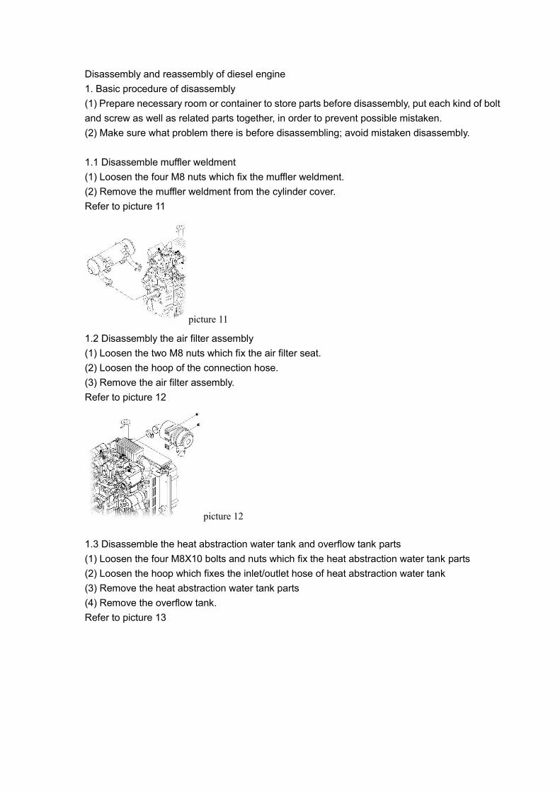
1.1 Disassemble muffler weldment
(1) Loosen the four M8 nuts which fix the muffler weldment.
(2) Remove the muffler weldment from the cylinder cover.
Refer to picture 11
picture 11
1.2 Disassembly the air filter assembly
(1) Loosen the two M8 nuts which fix the air filter seat.
(2) Loosen the hoop of the connection hose.
(3) Remove the air filter assembly.
Refer to picture 12
picture 12
1.3 Disassemble the heat abstraction water tank and overflow tank parts
(1) Loosen the four M8X10 bolts and nuts which fix the heat abstraction water tank parts
(2) Loosen the hoop which fixes the inlet/outlet hose of heat abstraction water tank
(3) Remove the heat abstraction water tank parts
(4) Remove the overflow tank.
Refer to picture 13

picture 13
1.4 Disassemble fan gasket、fan impeller and fan seat
(1) Loosen the four M6×25 bolts, which fix fan impeller and fan gasket and then remove the fan
impeller and fan gasket.
(2) Loosen the three M6×16 bolts which fix fan seat and then remove the fan seat.
Refer to picture 14
picture 14
1.5 Disassembly the air conduct cover parts
(1) Loosen the three M10X20 bolts which fix the air conduct cover parts on the flywheel end.
(2) Loosen the four M6X16 bolts which fix the air conduct cover parts on the engine seat.
(3) Remove the air conduct cover parts
Refer to picture 15
picture 15
1.6 Disassemble the inlet pressurizer tank
(1) Loosen the four M6X18 bolts which fix the inlet pressurizer tank parts on the cylinder cover

inlet flange end.
(2) Remove the inlet pressurizer tank parts.
Refer to picture 16
picture 16
1.7 Disassemble the water pipe weldment
(1) Loosen the M8X10 bolt which fixes the water pipe weldment on the crankcase cover
(2) Loosen the hoop which connects the thermostat connection pipe and water outlet pipe.
(3) Remove the water outlet pipe weldment.
Refer to picture 17
picture 17
1.8 Disassemble the thermostat parts, water outlet pipe seat and water outlet connection pipe.
(1) Loosen the two M6X40 bolts which fix the thermostat parts.
(2) Loosen the two M6X20 bolts which fix the water outlet pipe seat.
(3) Remove the thermostat parts, water outlet pipe seat and water outlet connection pipe.
Refer to picture 18
picture 18

1.9 Disassemble the rear support plate parts of starting motor and starting motor parts
(1) Loosen the M10X20 bolt which fixes the rear support plate of starting motor on the engine
side cover.
(2) Loosen the two M10X30 bolts which fix the starting motor parts.
(3) Remove the starting motor parts and rear support plate of starting motor.
Refer to picture 19
picture 19
1.10 Disassemble the cylinder cover parts
(1) Loosen the four M6X25 bolts which fix the cylinder cover.
(2) Remove the cylinder cover parts
Refer to picture 20
picture 20
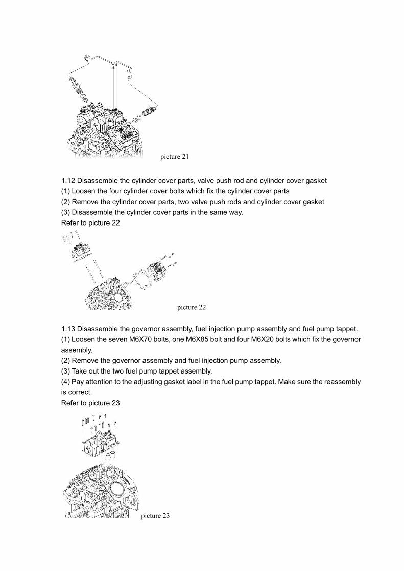
1.11 Disassemble the high pressure oil pipe parts and fuel injector assembly
(1) Loosen the tie of high pressure oil pipe which connects the fuel injection pump and fuel
injector. Remove the high pressure oil pipe parts.
(2) Loosen the fuel injector of the 1st cylinder, take out the fuel injector, two washer and heat
insulation sleeve from the cylinder cover.
(3) Disassemble the fuel injector of 2nd cylinder in the same way.
Refer to picture 21
picture 21
1.12 Disassemble the cylinder cover parts, valve push rod and cylinder cover gasket
(1) Loosen the four cylinder cover bolts which fix the cylinder cover parts
(2) Remove the cylinder cover parts, two valve push rods and cylinder cover gasket
(3) Disassemble the cylinder cover parts in the same way.
Refer to picture 22
picture 22
1.13 Disassemble the governor assembly, fuel injection pump assembly and fuel pump tappet.
(1) Loosen the seven M6X70 bolts, one M6X85 bolt and four M6X20 bolts which fix the governor
assembly.
(2) Remove the governor assembly and fuel injection pump assembly.
(3) Take out the two fuel pump tappet assembly.
(4) Pay attention to the adjusting gasket label in the fuel pump tappet. Make sure the reassembly
is correct.
Refer to picture 23
picture 23

1.14 Disassemble the flywheel parts and electromagnetic rotor parts
(1) Loosen the four M10X32 flywheel bolts which fix the flywheel on the crankshaft.
(2) Remove the flywheel parts and electromagnetic rotor parts.
Refer to picture 24
picture 24
1.15 Disassemble the stator coil parts
(1) Loosen the three M6X25 bolts and one bolt which fix the stator coil parts on the engine rear
end.
(2) Remove the stator coil parts
Refer to picture 25
picture 25
1.16 Disassemble the crankcase cover parts
(1) Loosen the seventeen M8X40 bolts which fix the crankcase cover.
(2) Remove the crankcase cover parts.
Refer to picture 26
picture 26

1.17 Disassemble the camshaft bearing cover and oil supplying camshaft.
(1) Loosen the two M6X16 inner hexagonal bolts which fix the camshaft bearing cover
(2) Remove the camshaft bearing cover and oil supplying camshaft.
(3) Screw on the bearing cover.
Refer to picture 27
picture 27
1.18 Disassemble the camshaft and valve tappet
(1) Draw out the camshaft parts from the crankcase.
(2) Take out the four valve tappets.
Refer to picture 28
picture 28
1.19 Disassemble the oil filter baffler weldment and oil filter parts
(1) Loosen the two M6X12 bolts which fix the oil filter baffler weldment and remove the oil filter
baffler weldment.
(2) Loosen the oil filter parts with a special spanner and remove the oil filter parts.
Refer to picture 29
picture 29
1.20 Disassemble the piston connection rod assembly
(1) Loosen the connection rod bolts of 1st cylinder and 2nd cylinder to remove the connection rod
cover.
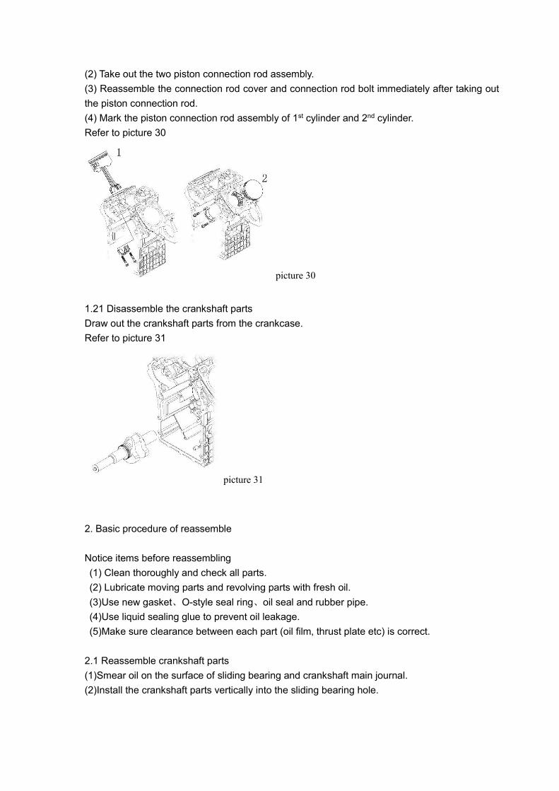
(2) Take out the two piston connection rod assembly.
(3) Reassemble the connection rod cover and connection rod bolt immediately after taking out
the piston connection rod.
(4) Mark the piston connection rod assembly of 1st cylinder and 2nd cylinder.
Refer to picture 30
picture 30
1.21 Disassemble the crankshaft parts
Draw out the crankshaft parts from the crankcase.
Refer to picture 31
picture 31
2. Basic procedure of reassemble
Notice items before reassembling
(1) Clean thoroughly and check all parts.
(2) Lubricate moving parts and revolving parts with fresh oil.
(3)Use new gasket、O-style seal ring、oil seal and rubber pipe.
(4)Use liquid sealing glue to prevent oil leakage.
(5)Make sure clearance between each part (oil film, thrust plate etc) is correct.
2.1 Reassemble crankshaft parts
(1)Smear oil on the surface of sliding bearing and crankshaft main journal.
(2)Install the crankshaft parts vertically into the sliding bearing hole.

2.2 Reassemble piston connecting rod assembly
(1)Smear fresh oil on piston ring、piston pin、cylinder cover and connecting rod big-end hole.
(2)The opening of piston ring should be staggered: the 1st ring and the 2nd ring staggered 180°,
the 2nd ring and the 3rd ring staggered 100°. Avoid piston main pushing side, lean piston skirt
flute on the side of main oil duct. Refer to picture 32
Picture 32
(3)Install disassembled piston connecting rod parts into cylinder cover according to original
cylinder number, clamp piston ring with special tools, push piston into cylinder, then close the
connecting rod cover. Notice that connecting rod body and bush locating skirt of connecting rod
cover should be on the same side, never turnaround.
(4)Smear thread fasten glue on thread of connecting rod bolt, tighten uniformly to stipulate
tighten torque for three times (28±2)N·m
(5)Rock connecting rod cover with hands, it should move smoothly and can’t be seized.
2.3 Reassemble the oil filter parts and oil filter baffler weldment
(1) Smear fresh oil on the oil filter parts seal ring and screw it on the connection turnbuckle.
(2) Screw on the oil filter parts with special spanner (for about 3/4 circuit)
(3) Reassemble the oil filter baffler weldment and fix it with two M6X12 bolts.
2.4 Reassemble valve tappet and camshaft parts
(1) Smear little fresh oil on the surface of valve tappet, and install them into the upper valve
tappet hole.
(2) Smear little fresh oil on the camshaft and install it into the camshaft hole, make sure the
joggle label on the camshaft timing gear matches with that of the crankshaft timing gear.
(3) Revolve the crankshaft and check the joggle of two timing gears.
2.5 Reassemble the oil supplying camshaft and camshaft bearing cover
(1) Smear little fresh oil on the oil supplying camshaft and install it into the camshaft hole.
(2) Install the camshaft bearing cover on the bearing seat and fix it with two M6X16 inner
hexagonal bolts.

2.6 Reassemble the crankcase cover parts
(1) Smear little seal gum on the crankcase cover.
(2) Install the crankcase cover and fix it with seventeen M8X40 bolts.
2.7 Reassemble the stator coil parts
(1) Install the stator coil parts on the flywheel end.
(2) Fix it with three M6X25 bolts.
2.8 Reassemble the oil seal, flywheel and electromagnetic rotor parts
(1) Smear little fresh oil on the oil seal lips and install it vertically into the crankcase cover oil
seal hole. Pay attention not to roll or lean it.
(2) Install the flywheel and electromagnetic rotor parts on the crankshaft flywheel end.
(3) Fix the flywheel on the crankshaft end with four M10X32 flywheel bolts.
2.9 Reassemble the fuel pump tappet, governor assembly and fuel injection pump assembly
(1) Smear little fresh oil on the two tappets and install them into the tappet hole on the engine
top.
(2) Smear seal gum on the governor installation face.
(3) Fix the governor assembly and fuel injection pump assembly on the engine top with seven
M6X70 bolts, one M6X85 bolt and two M6X20 bolts.
2.10 Reassemble the cylinder cover gasket, valve push rod and cylinder cover assembly.
(1) Smear little seal gum on both sides of cylinder cover gasket, install it on the engine top.
(2) Smear little fresh oil on the valve push rod and Install it the valve tappet hole.
(3) Install the 1st cylinder cover assembly on the cylinder cover, screw on the two cylinder cover
long bolts and cylinder cover short bolts, the torque is (60±5)N·m.
(4) Reassemble the 2nd cylinder cover assembly in the same way.
2.11 Reassemble the fuel injector assembly and high pressure oil pipe parts
(1) Install the two fuel injector washers and one fuel injector heat insulation sleeve into the fuel
injector hole and then screw on the fuel injector assembly. The torque is (50±5)N·m.
(2) Reassemble the other fuel injector assembly in the same way.
(3) Install the high pressure oil pipe parts on the fuel injection pump assembly and fuel injector
assembly. Fix them securely.
2.12 Reassemble the cylinder cover parts
(1) Install the cylinder coverⅠ, and fix it with four M6X24 bolts.
(2) Install the cylinder coverⅡ in the same way.
2.13 Reassemble the support plate parts and starting motor parts
(1) Install the rear support plate on the starting motor rear end.
(2) Install the starting motor into the motor hole and fix it with two M10X30 bolts.
(3) Fix the rear support plate with one M10X20 bolt.
2.14 Reassemble the thermostat parts, water outlet pipe seat and water outlet connection pipe
(1) Install the thermostat parts on the water outlet flange face of 1st cylinder cover and fix it with
two M6X40 bolts.
(2) Install the water outlet pipe seat on the water outlet flange face of 2nd cylinder cover and fix
it with two M6X20 bolts.
(3) Check the hoop of water outlet connection pipe which connects the thermostat parts and
water outlet pipe seat.
2.15 Reassemble the water outlet pipe weldment
(1) Fix the water outlet pipe weldment with one M8X10 bolt.
(2) Connect the thermostat and water outlet pipe weldment with a hose and lock it with hoop 40.
2.16 Reassemble the inlet pressurizer tank parts
(1) Install the 0-seal ring 40X2.65 on the inlet flange groove of pressurizer tank.
(2) Install the flange face of inlet pressurizer tank on the cylinder cover inlet port and fix it with
two M6X18 bolts.
2.17 Reassemble the air conduct cover parts
(1) Install the air conduct cover parts on the flywheel end and fix it with three M10X20 bolts.
(2) Fix the air conduct cover seat and engine seat with four M6X18 bolts.
2.18 Reassemble the fan seat, fan gasket and fan impeller
(1) Install the fan seat on the flywheel end and fix it with three M6X16 bolts.
(2) Fix the fan gasket and fan impeller on the fan seat with four M6X20 bolts.
2.19 Reassemble the heat abstraction tank and overflow tank parts
(1) Install the heat abstraction tank and fix it with four M8X110 bolts and nuts.
(2) Install the overflow tank.
(3) Connect the water inlet port and outlet pipe weldment with a water tank connection hose and
lock it with hoop 40.
(4) Connect the water outlet port and water pump inlet port with a water pump inlet hose and
lock it with hoop 40.
2.20 Reassemble the air filter assembly
(1) Fix the installation seat of air filter with two M8 nuts and washers.
(2) Connect the connection hose of pressurizer tank with the inlet port of air filter, and lock it with
hoop.
2.21 Reassemble the muffler weldment
(1) Install the muffler weldment on the cylinder cover and fix it with four M8 nuts.

Check and maintain
1. Cylinder cover
1.1 Combustion chamber surface of cylinder cover
Disassemble fuel injector、 inlet valve and exhaust valve, clean the surface of combustion
chamber and see whether there is any crack or other damage. Use smear infiltration to check
minute crack.
1.2 Inlet/exhaust valve seat
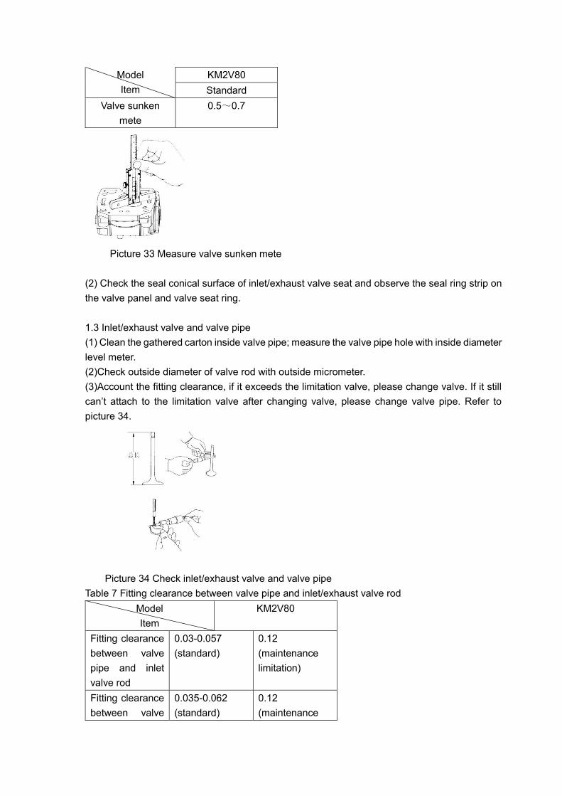
(1) Clean cylinder cover、valve and valve sealing cone, insert valve into valve pipe, measure
valve sunk mete with deep vernier caliper, refer to picture 33. If the valve sunken mete or valve
ring width exceeds much, please adjust it by changing valve or valve seat gasket.
Table 6 Valve sunken mete
Model
Item
KM2V80
Standard
Valve sunken
mete
0.5~0.7
Picture 33 Measure valve sunken mete
(2) Check the seal conical surface of inlet/exhaust valve seat and observe the seal ring strip on
the valve panel and valve seat ring.
1.3 Inlet/exhaust valve and valve pipe
(1) Clean the gathered carton inside valve pipe; measure the valve pipe hole with inside diameter
level meter.
(2)Check outside diameter of valve rod with outside micrometer.
(3)Account the fitting clearance, if it exceeds the limitation valve, please change valve. If it still
can’t attach to the limitation valve after changing valve, please change valve pipe. Refer to
picture 34.
Picture 34 Check inlet/exhaust valve and valve pipe
Table 7 Fitting clearance between valve pipe and inlet/exhaust valve rod
Model
Item
KM2V80
Fitting clearance
between valve
pipe and inlet
valve rod
0.03-0.057
(standard)
0.12
(maintenance
limitation)
Fitting clearance
between valve
0.035-0.062
(standard)
0.12
(maintenance

pipe and
exhaust valve
rod
limitation)
1.4 Valve spring
(1)Measure the free length of valve spring with vernier caliper, and change the valve spring if the
free length exceeds limitation valve.
(2)Measure the valve spring verticality; revolve valve spring to see whether the whole side of
valve spring is connected with the square ruler. Change valve spring if the measured verticality
exceeds the limitation valve.
Refer to picture 35
Table 8 Free length and verticality of valve spring
Model
Item
KM2V80
Standard
Valve spring free
length
39.5
Valve spring
verticality
0.5
Picture 35 Measure valve spring
(3)Check whether there is any crack or corrosion on the valve spring surface, if there is any,
please change it.
1.5 Lube oil clearance between rockshaft and valve rocker hole
Measure the outside diameter of rockshaft with outside micrometer; measure the aperture of
valve rockshaft hole with inside lever meter. Then account lube oil clearance, if the measured
lube oil clearance exceeds limitation value, please change rockshaft and valve rocker arm. Refer
to picture 36
Table 9 Fitting clearance of valve rocker arm hole and rockshaft diameter
Model
Item
KM2V80
Standard Service
limitation
Valve rocker arm hole and 0.016~ 0.12

rockshaft diameter 0.045
Picture 36 Measure lube oil clearance between rockshaft and valve rocker arm hole
1.6 Adjust valve clearance
Adjust valve clearance when the generator is at cooling state. Refer to picture 37
Table 10 Clearance of inlet and exhaust valve
Model
Item
KM2V80
Standard
Inlet valve clearance 0.10~0.15
Exhaust valve clearance 0.10~0.15
Picture 37 Adjust valve clearance
1.7 Measure cylinder compression clearance height
(1)Disassemble cylinder cover, put fuse ф1.5×10mm of the same height on the four points of
piston top, reassemble cylinder cover, screw on cylinder cover bolts according to the stipulated
order and torque.
(2)Revolve crankshaft in anticlockwise direction, flat fuse, disassemble cylinder cover and take
out the flat fuse, and measure its thickness. Take the average valve of four fuses as cylinder
compression clearance. Refer to picture 38.
Table 11 Piston top clearance
Model
Item
KM2V80
Standard
Piston top
clearance
0.88~1.20

Picture 38 Measure piston top clearance
2 Camshaft parts
2.1 Lube oil clearance of camshaft axial diameter
Measure the camshaft journal with outside micrometer, measure inside diameter of camshaft
hole with inside diameter lever meter, account the lube oil clearance. If the measured valve
exceeds the limitation valve, please change camshaft. Refer to picture 39.
Table 12 Fitting clearance between camshaft aperture and camshaft axial diameter
Model
Item
KM2V80
Standard Service
limitation
Camshaft aperture and
camshaft axle diameter
0.032-
0.061
0.15
Picture 39 Measure lube oil clearance of camshaft axial diameter
2.2 Height of cam
Measure the height of cam at its top point with outside micrometer, if the measured height
exceeds the limitation valve, please change for a new camshaft. (Height for inlet/exhaust cam is
31.13+0.03
-0.50 ). Refer to picture 40.

Picture 40 Measure the height of cam
2.3 Lube oil clearance of camshaft axial diameter
Measure camshaft journal with outside micrometer, measure inside diameter of camshaft hole
with inside diameter lever meter; account the lube oil clearance. If the measured clearance
exceeds the limitation valve, please change the camshaft. Refer to picture 41.
Picture 41 Measure fitting clearance of camshaft aperture and axial diameter of oil supplying
camshaft
Model
Item
KM2V80
Standard Service
limitation
Camshaft aperture and
axial diameter of oil
supplying camshaft
0.032~
0.061
0.15
2.4 Valve tappet
(1) Check the upper part of tappet. The tappet center line is supposed to be off-centering to the
camshaft center, so that to avoid uneven wearing. Change the tappet if it wears severely.
(2) Check the tappet surface. Change the tappet if it is damaged or worn.
3. Piston and piston pin
3.1 Piston
(1) Check piston top surface, clear up the gathered carton on it, please be careful and don’t hurt
the surface.
(2) Check piston outside diameter, if damage of piston surface or ring groove exceeds the
limitation value, please change for a new piston.
(3) Check inside diameter of piston pin hole, if the value of it exceeds the limitation value, please
change for a new piston. Refer to picture 42.

Picture 42 Check the inside diameter of piston pin hole
3.2 Piston ring
(1) Use special tools to assemble or disassemble piston ring, don’t separate piston ring too hard.
(2) Clear up the gathered carton in the ring groove; use thickness gauge or depth gauge to
measure the clearance between piston ring and ring groove. If the measured value exceeds the
limitation value, please replace piston ring or piston. If the clearance is too big, air leakage will
be caused, and then result in leakage of lube oil. Refer to picture 43.
Table 14 Clearance between piston ring and ring groove
Model
Item
KM2V80
Standard Service
limitation
Height of ring groove and
thickness of the 1st ring
0.05~
0.08
0.15
Height of ring groove and
thickness of the 2nd ring
0.03~
0.06
0.15
Height of ring groove and
thickness of the 3rd ring
0.02~
0.065
0.15
Picture 43 Check clearance between piston ring and ring groove
(3) Assemble piston ring to damage parts of cylinder cover, measure piston ring gap clearance
with thickness gauge. If the measured value exceeds the limitation value, replace piston ring or
cylinder cover. Refer to picture 44
Table 15 Gap clearance of piston ring
Model
Item
KM2V80
Standard

Gap clearance of the 1st ring 0.25~0.35
Gap clearance of the 2nd ring 0.20~0.35
Gap clearance of the 3rd ring 0.15~0.30
Picture 44 Measure the gap clearance of piston ring
3.3 Piston pin
Measure the outside diameter of piston pin, if the measured value exceeds the maintenance
limitation, or has been grinded severely into echelon form, then you should replace the piston
pin. Refer to picture 45.
Table 16 Fitting clearance between piston pin hole diameter and piston pin diameter
Model
Item
KM2V80
Standard Service
limitation
Piston pin hole diameter
and piston pin diameter
0.004~
0.008
0.025
Picture 45 Measure outside diameter of piston pin and diameter of connection rod bushing hole
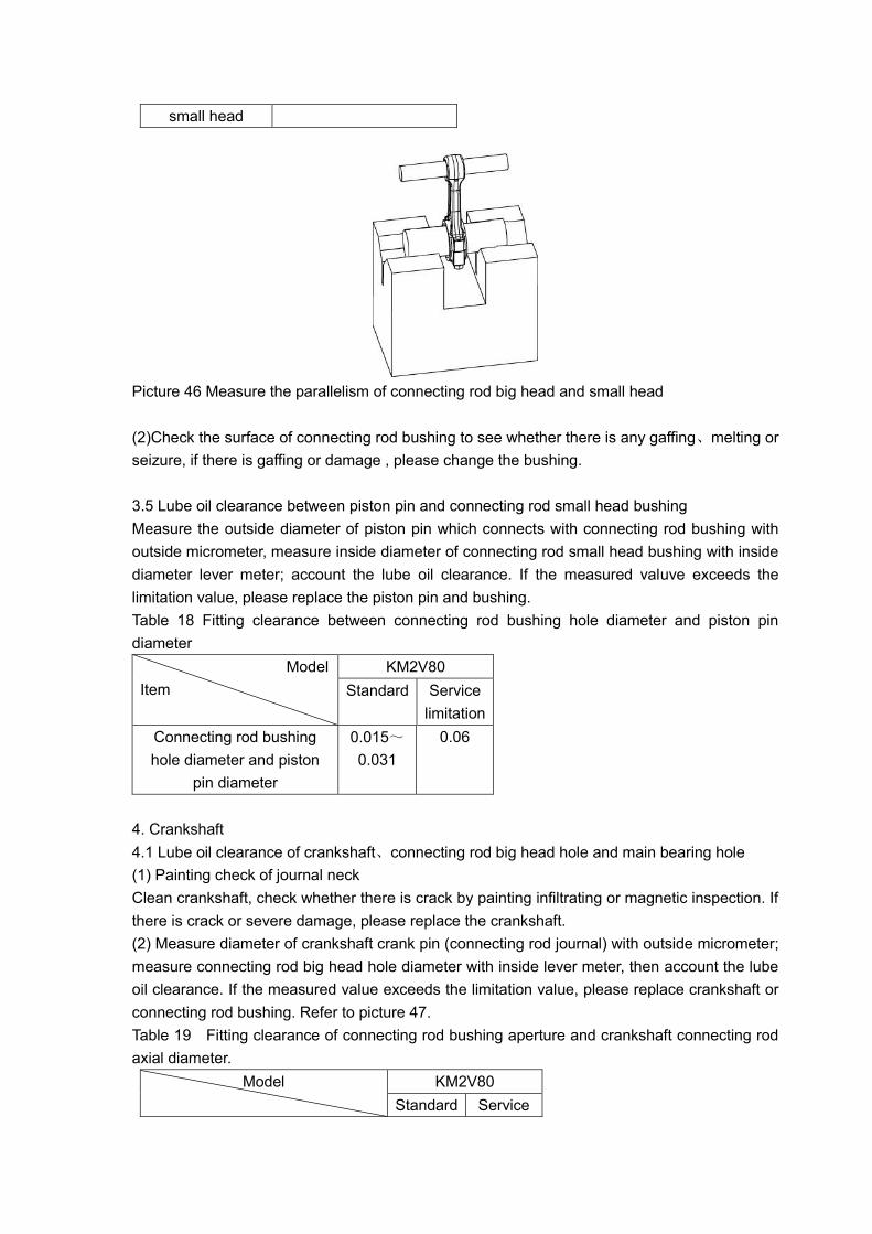
3.4 Connecting rod
(1) Check parallelism and torsion deformation of connection rod big head and small head. Clamp
measurement in the big head hole and small head hole to check the its depth of parallelism and
distortional deformation. If the depth of parallelism exceeds promised limitation, please replace
connecting rod. Refer to picture 46.
Table 17 Parallelism of connection rod big head hole and small head hole
Model
Item
KM2V80
Standard
Parallelism of
connection rod
big head and
0.04/100
small head
Picture 46 Measure the parallelism of connecting rod big head and small head
(2)Check the surface of connecting rod bushing to see whether there is any gaffing、melting or
seizure, if there is gaffing or damage , please change the bushing.
3.5 Lube oil clearance between piston pin and connecting rod small head bushing
Measure the outside diameter of piston pin which connects with connecting rod bushing with
outside micrometer, measure inside diameter of connecting rod small head bushing with inside
diameter lever meter; account the lube oil clearance. If the measured valuve exceeds the
limitation value, please replace the piston pin and bushing.
Table 18 Fitting clearance between connecting rod bushing hole diameter and piston pin
diameter
Model
Item
KM2V80
Standard Service
limitation
Connecting rod bushing
hole diameter and piston
pin diameter
0.015~
0.031
0.06
4. Crankshaft
4.1 Lube oil clearance of crankshaft、connecting rod big head hole and main bearing hole
(1) Painting check of journal neck
Clean crankshaft, check whether there is crack by painting infiltrating or magnetic inspection. If
there is crack or severe damage, please replace the crankshaft.
(2) Measure diameter of crankshaft crank pin (connecting rod journal) with outside micrometer;
measure connecting rod big head hole diameter with inside lever meter, then account the lube
oil clearance. If the measured value exceeds the limitation value, please replace crankshaft or
connecting rod bushing. Refer to picture 47.
Table 19 Fitting clearance of connecting rod bushing aperture and crankshaft connecting rod
axial diameter.
Model
KM2V80
Standard Service

Item limitation
Connecting rod bushing aperture
and crankshaft connecting rod
axial diameter
0.025~
0.062
0.15
Picture 47 Check the connecting rod axial diameter
(3) Check crankshaft main journal diameter with outside micrometer, measure main bearing hole
diameter with inside lever meter, then account the lube oil clearance. If the measured value
exceeds limitation value, please replace crankshaft or main bushing. Refer to picture 48.
Table 20 Fitting clearance of main bearing hole and main axial diameter
Model
Item
KM2V80
Standard Service
limitation
Main bearing hole and main axial
diameter
0.040~
0.071
0.15
Picture 57 Measure main bearing hole and main axial diameter
5. Cylinder block and cylinder cover
Measure the inner diameter of cylinder cover. If the measured value exceeds the limitation value,
please bore the cylinder again and use the bigger size piston. Refer to picture 49
Table 21 Cylinder cover diameter
Model
Item
KM2V80
Standard
Cylinder cover
diameter
80.00~80.03

Picture 49
6. Lubricating system
6.1 Clearance between outer rotor hole and outer rotor
Measure the axial diameter of outer rotor with outside micrometer, and measure the oil pump
outer rotor hole on the crankcase cover with inner level meter, account the lube oil clearance. If
the measured value exceeds the limitation value, please change the oil pump parts. Refer to
picture 50.
Table 22 Clearance between outer rotor hole and outer rotor
Model
Item
KM2V80
Standard Maintenance
limitation
Clearance
between outer
rotor hole and
outer rotor
0.075~0.14 0.20
Picture 50 Clearance between outer rotor hole and outer rotor
6.2 Clearance between rotor pump shaft hold and rotor pump shaft
Measure the rotor pump shaft diameter with outside micrometer and measure the rotor pump
shaft hole diameter with level meter, account the lube oil clearance. If the measured value
exceeds the limitation value, please change the oil pump rotor parts. Refer to picture 51.

Table 23 Clearance between rotor pump shaft hole and rotor pump shaft
Model
Item
KM2V80
Standard Maintenance
limitation
Clearance
between rotor
pump shaft
hole and rotor
pump shaft
0.016~0.045 0.10
Picture 51 Measure the clearance between rotor pump shaft hole and rotor pump shaft
6.3 Axial clearance of oil pump
(1) Measure the depth of oil pump hole on the crankcase cover with depth meter.
(2) Measure the axial thickness of inner/outer rotor with outside micrometer.
(3) Account the axial clearance. If the measured value exceeds the limitation value, please
change the oil pump rotor parts. Refer to picture 52.
Table 24 Axial clearance of oil pump
Model
Item
KM2V80
Standard Maintenance
limitation
Axial clearance of
oil pump
0.04~0.10 0.15
Picture 52 Axial clearance of oil pump
7. Cooling system

7.1 Opening temperature of thermostat
Add a piece of line between valves of thermostat, put thermostat and a temperature gauge into
a barrel. Heat the water in barrel gradually, hold on the line and hang thermostat in air.
Thermostat will open as the water temperature increases, please read the temperature. Go on
heating, when the thermostat opens for about 6mm, then read again the temperature. If the
temperature is not in the leaving factory range, you should replace thermostat. Refer to picture
53.
Table 25 Temperature of thermostat
Model
Item
KM2V80
Standard
Opening
temperature of
thermostat
69.5◎~72.5◎
Complete opening
temperature of
thermostat
85◎
Picture 53 Measure the temperature of thermostat
7.2 Check water leakage of radiator
Fill some water into radiator, install radiator tester, and increase water pressure to 137kPa.
Check the water leakage of radiator, if the water leakage is too much, please replace radiator. If
the water leak hole is small, please adjust with radiator filling agent. Refer to picture 54.
Picture 54 Check water leakage of radiator

8 Fuel system
8.1 Check fuel injection pressure
Install fuel injector on fuel injector tester, remove test handle of fuel injector slowly, and check
the instant pressure when fuel is ejected out. If the measured valve is not within the limitation
range, please replace fuel injection gasket.
8.2 Check spray of fuel injector
Install fuel injector on fuel injector tester, and check the spray of fuel injector. If the quality of
spray is not good, please replace fuel injector parts. Refer to picture 55.
Picture 55 Check the spray of fuel injector
8.3 Check the sealing of fuel injector seat
Install fuel injector on fuel injector tester, raise the fuel pressure, and keep it at 12.7MPa for 10s.
If there is oil leakage, please replace fuel injector parts. Refer to picture 56.
Picture 56 Check the sealing of fuel injector seat

Starting System
1. Starter motor
1.1Check starter motor Refer to Fig 57
(1)Remove the motor excitation & armature winding outlet line from starter motor C wiring
terminal
(2)Connecting the motor case to battery anode with conducting wire.
(3)When connecting the motor case to battery cathode with conducting wire, the motor should
revolve, if not, please check the two windings of the motor.
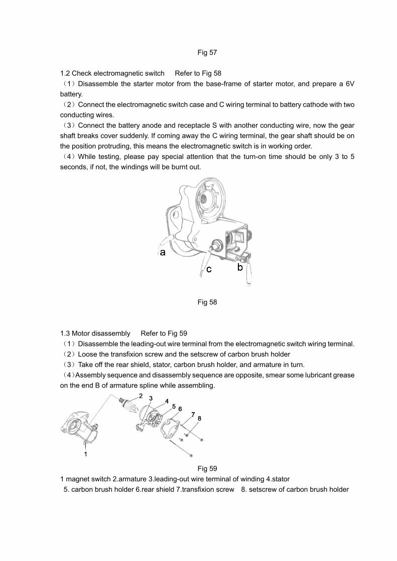
Fig 57
1.2 Check electromagnetic switch Refer to Fig 58
(1)Disassemble the starter motor from the base-frame of starter motor, and prepare a 6V
battery.
(2)Connect the electromagnetic switch case and C wiring terminal to battery cathode with two
conducting wires.
(3)Connect the battery anode and receptacle S with another conducting wire, now the gear
shaft breaks cover suddenly. If coming away the C wiring terminal, the gear shaft should be on
the position protruding, this means the electromagnetic switch is in working order.
(4)While testing, please pay special attention that the turn-on time should be only 3 to 5
seconds, if not, the windings will be burnt out.
Fig 58
1.3 Motor disassembly Refer to Fig 59
(1)Disassemble the leading-out wire terminal from the electromagnetic switch wiring terminal.
(2)Loose the transfixion screw and the setscrew of carbon brush holder
(3)Take off the rear shield, stator, carbon brush holder, and armature in turn.
(4)Assembly sequence and disassembly sequence are opposite, smear some lubricant grease
on the end B of armature spline while assembling.
Fig 59
1 magnet switch 2.armature 3.leading-out wire terminal of winding 4.stator
5. carbon brush holder 6.rear shield 7.transfixion screw 8. setscrew of carbon brush holder

1.4 Electromagnetic switch dismounting Refer to Fig 60
(1)Loose the three screws of end cover
(2)Take off end cover 1 and magnet iron core.
Fig 60
1.5 Decelerating clutch dismounting Refer to Fig 61
(1)Loose three bolts which tighten the driving shell ,(two are outside of motor, one is inside of
motor),
(2)Take off driving shell, clutch subassembly, steel ball, return spring and drive gear in turn.
(3)When assembling, please smear some fresh lube oil.
1. driving shell 2.decelerating clutch 3.steel ball 4. return spring
5. electromagnetic switch 6.driving gear 7.idler gear 8. drive gear
Fig 61
1.6 Starter motor inspection and maintenance
1.6.1Commutator inspection and maintenance
(1)Check wearing of the commutator, if slightly worn, burnishing and polishing with fine rubber
(Refer to Fig 62),

Fig 62 Fig 63
(2)Measure diameter of commutator with outside micrometer, if the measured value is smaller
than the limitation size, please change armature. (Refer Fig 63)
(3) If there is much difference between excircle wire harness of commutator and axes
parallelism, while the minimum size limitation of axial diameter is in the allowable range. Please
modify to the specified value on the lathe. Refer to Fig 64 ,
Fig (a) is good, Fig (b) is bad.
Fig 64
1.6.2 Check the electric brush wear Refer to Fig 65
(1)If there is soil and dust on the wearing surface, please burnish with abrasive cloth.
(2)Measure the electric brush height with slide gauge. If A is abrasive (means A’s size is
smaller), please replace the electric brush.
Fig 65
1.6.3 Check electric brush holder Refer to Fig 66
Check the insulating property between the insulating electric brush holder and supporting plate,
if it is current conducting, please replace the electric brush holder.
Fig 66

1.6.4 Check armature Refer to Fig 67
Check the electric conductivity with ohmmeter between the commutator copper sheet and the
armature core or armature winding:
(1)If the commutator copper sheet and armature core are current conducting, please replace
armature.
(2)If commutator copper sheet and armature winding are not current conducting, please
replace armature.
(3)If the commutator copper sheet is current conducting each other, please replace armature.
(Refer to Fig 68)
Fig 67 Fig 68
Engine electrical system
1.6.5 Check stator winding
(1) Test electricity of stator winding outgoing line with an ohmmeter, if no conductivity, please
replace stator. Refer to Fig. 69
(2) Test insulatibity between stator winding and stator shell with an ohmmeter, if it is conductive,
please replace stator. Refer to Fig.70.
Fig. 69 Fig. 70
1.6.6 Check armature roll bearing
Small radial and axial clearance, smooth running of roll bearing. If big vibration, clagging or
damages happen, please replace the roll bearing.
1.6.7 Check retarder clutch. Refer to Fig.71
(1) Check all gears of retarder clutch, if severe aging or damage happens, please replace
retarder clutch or related gear.
(2) Check flexibility of retarder clutch. Smooth radial operation and rotation must be secured.
No skid when given a force, normal performance maintained, otherwise please replace.

Fig.71
1.6.8 Check electromagnetic switch. Refer to Fig.72
Test electricity conductivity of contact disc in electromagnetic switch. Hold magnetic core with
your thumb (Refer to Fig.68), test electricity conductivity between wire holder C and B. If no
conductivity, please check contact and fastening between two wire holders and inner copper
sheet.
Fig.72
2. Glow plug
(1) Check the resistance between center screw and installation thread, resistance of 0.9~1.2Ω
indicates good performance of glow plug. Refer to picture 73
(2) Resistance of 0Ωindicates short circuit between center screw and outer shell. Please change
the glow plug.
(3) If the measured value is not the standard value, please change the glow plug.
Picture 73
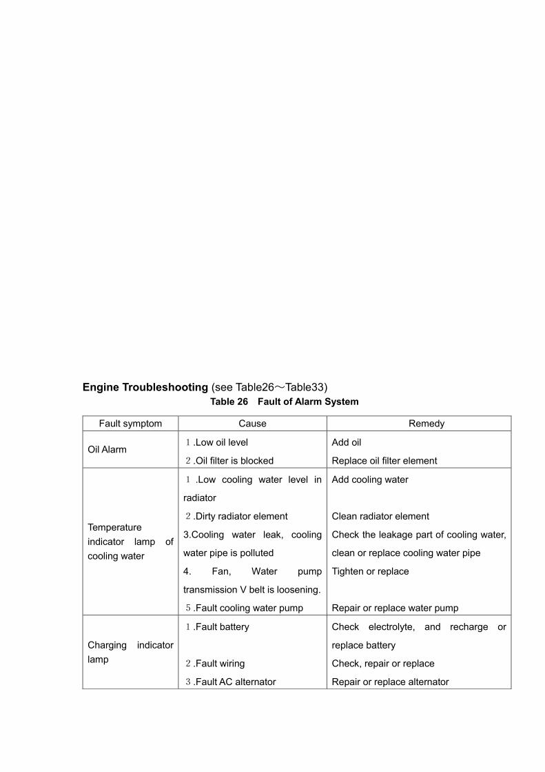
Engine Troubleshooting (see Table26~Table33)
Table 26 Fault of Alarm System
Fault symptom Cause Remedy
Oil Alarm 1.Low oil level
2.Oil filter is blocked
Add oil
Replace oil filter element
Temperature
indicator lamp of
cooling water
1 .Low cooling water level in
radiator
2.Dirty radiator element
3.Cooling water leak, cooling
water pipe is polluted
4. Fan, Water pump
transmission V belt is loosening.
5.Fault cooling water pump
Add cooling water
Clean radiator element
Check the leakage part of cooling water,
clean or replace cooling water pipe
Tighten or replace
Repair or replace water pump
Charging indicator
lamp
1.Fault battery
2.Fault wiring
3.Fault AC alternator
Check electrolyte, and recharge or
replace battery
Check, repair or replace
Repair or replace alternator

Table 27 Fault Starting
Fault
sympt
om
Cause Remedy
Fault
Fuel
supply
syste
m
1.No fuel in fuel tank
2 .Air existed in the fuel supply
system
3 . Electron magnetic stop valve
does not work
4.Unqualified fuel
5.Dirty air filter
6.Low environmental temperature
7.Fuel filter is blocked
8.Incorrect fuel supply timing
9.Blocked nozzle
10. Incorrect air intake and outlet
valve clearance
11. Poor inside compress of Cylinder
(1)Leakage of air valve
(2)Cylinder, piston, piston rings are
worn out
12.Starting fuel supply is not enough
for fuel pump
Add fuel
Eliminate air
Check the function of electron magnetic stop valve
with electricity, then repair or replace
Replace fuel with correct specification
Replace air filter element
Use air heater
Replace fuel filter element
Check and adjust fuel supply advanced angle
Check or replace nozzle
Check and adjust valve clearance
Check the cylinder inside compress pressure standard
value 3.1Mpa, with lowest value 2.2Mpa
Check or skive air valve
Repair by professional technician
Check and adjust the fuel pump on the test table
Fault
circuit
1. Battery without enough electricity
or loosen connector
2. Starter does not work properly,
only run idle
3. Hard meshing for starter
4.Low running speed of starter
Check the wiring connector or the electrolyte level and
proportion in the battery and recharge the battery
Adjust the joggle position between starter and flywheel
gear ring surface
Battery pressure is heavy in winter or the battery cable
is slightness
Low air intake
pressure indicator
lamp
Dirty air filter element Clean the filter element through
compressive air or replace

Table 28 Abnormal smoke of exhaust air
Fault symptom Cause Remedy
Black smoke
1.Overload for diesel engine
2.Blocked air filter
3.Unqualified fuel
4.Large air valve clearance
5.Blocked nozzle or leaked nozzle
6.Incorrect fuel supply timing
7.Air valve without good seal
8. Cylinder, piston, piston rings are
worn
Reduce the load
Clean or replace air filter element
Use fuel with correct specification
Check and adjust air valve clearance
Check the injected fuel pressure and
injected frog quality
Check and adjust fuel supply advance
angle
Check the seal ring, repair and rubbing
Replace or repair
Blue smoke
1.High oil level
2.Breather with too much oil frog
3.Ineffective air valve oil seal, large
clearance of air valve rod
4.Opposite position of the second ring
Check the oil level in the oil base pan by
oil dip stick, and release oil
Check seal of the breather valve plate
and check if the oil return hole is smooth
Replace air valve oil seal or repair air
valve and conduit
Check and modify (Oil fleecing part is
undersurface)
White smoke
1. For it is cold in winter, it is normal to
exhaust white smoke at the beginning.
As the temperature becomes higher,
the white smoke will disappear.
2. The fuel is mixed with water, and
there is water steam exhausted
3. The injected fuel is not atomized,
and the fuel steam is exhausted.
4. The fuel injection advance angle is
too late, the fuel gas is exhausted.
5. There is leakage in cylinder, cylinder
head and cylinder gasket.
Drain the water by the fuel drain plug of
the fuel tank
Check fuel injection pressure and
injection frog quality
Check and adjust fuel supply advance
angle
Find the reason that cooling water flow
into the cylinder and repair the problem
Table 29 Insufficient Power of Engine
Fault symptom Cause Remedy
Insufficient
power of engine
1. Air filter element is too dirty, and the
air intake is not smooth
2. Fuel filter element is too dirty, and
the Fuel supply is unsmooth
3. Fuel pipe is blocked, the fuel supply
Clean or replace air filter element
Clean or replace fuel filter element
Check and clean or replace fuel pipe
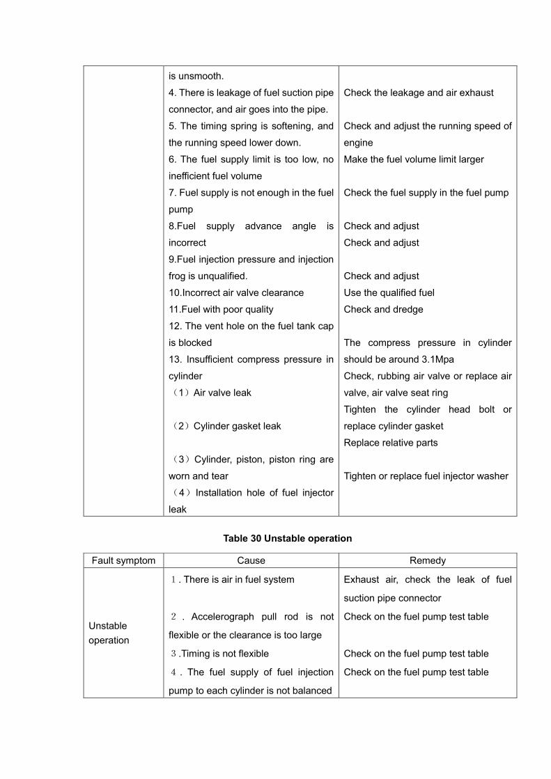
is unsmooth.
4. There is leakage of fuel suction pipe
connector, and air goes into the pipe.
5. The timing spring is softening, and
the running speed lower down.
6. The fuel supply limit is too low, no
inefficient fuel volume
7. Fuel supply is not enough in the fuel
pump
8.Fuel supply advance angle is
incorrect
9.Fuel injection pressure and injection
frog is unqualified.
10.Incorrect air valve clearance
11.Fuel with poor quality
12. The vent hole on the fuel tank cap
is blocked
13. Insufficient compress pressure in
cylinder
(1)Air valve leak
(2)Cylinder gasket leak
(3)Cylinder, piston, piston ring are
worn and tear
(4)Installation hole of fuel injector
leak
Check the leakage and air exhaust
Check and adjust the running speed of
engine
Make the fuel volume limit larger
Check the fuel supply in the fuel pump
Check and adjust
Check and adjust
Check and adjust
Use the qualified fuel
Check and dredge
The compress pressure in cylinder
should be around 3.1Mpa
Check, rubbing air valve or replace air
valve, air valve seat ring
Tighten the cylinder head bolt or
replace cylinder gasket
Replace relative parts
Tighten or replace fuel injector washer
Table 30 Unstable operation
Fault symptom Cause Remedy
Unstable
operation
1. There is air in fuel system
2 . Accelerograph pull rod is not
flexible or the clearance is too large
3.Timing is not flexible
4 . The fuel supply of fuel injection
pump to each cylinder is not balanced
Exhaust air, check the leak of fuel
suction pipe connector
Check on the fuel pump test table
Check on the fuel pump test table
Check on the fuel pump test table

Table 31 Overheat of Engine
Table 32 Sudden Stop
5. The injected frog of fuel injector is
in poor quality with fuel drop
Check on the fuel pump test table
Fault symptom Cause Remedy
High
temperature of
supplied water
1. Insufficient cooling water in water
tank
2. Air existed in the cooling water tank
3.Overload of engine
4 . Fan belt is loosen to make the
running speed lower
5.Blocked cooling water pipe
6.Too late to inject fuel
7.Combustion is abnormal
8.Dirty water tank surface
9 . There is begrime in the cooling
system
10. Damaged thermostat
11.Water pump does not work properly
12.Water temperature meter does not
work
Add cooling water
Add cooling water or exhaust air
Deduce the load
Tighten or replace the belt
Check or replace
Adjust fuel supply advance angle
Check the injected frog quality
Clean the water tank radiator element
Clean the furring and rust in
professional way
Replace thermostat
Check or replace water pump
Replace
High oil
temperature
1.Higher or lower oil level
2.Poor oil quality
3. Air leak in the piston ring
4.High temperature of cooling water
5.Overload of diesel engine
6.Fault water temperature meter
Check the oil level by oil dip stick
Use the oil with correct specification
Check if cylinder, piston ring are worn,
clip and the connecting rod of cylinder
Check as showed above
Deduce the load
Replace
Fault
symptom
Cause Remedy
Sudden
stop
1. No fuel in the fuel tank
2. There is leak in the fuel pipe, and air
goes into the fuel pipe
Add fuel
Check the leak, and exhaust air

Table 33 Abnormal noise in engine while running
3. Blocked fuel filter element
4 .No electricity of fuel pump electron
magnetic stop valve, and cut the fuel
supply
5. Fuel pump does not work properly
6. Damaged fuel injection pump
7.No rotation of crankshaft
(1)Broken plain journal bearing of piston,
blocked cylinder
(2)Low oil pressure or broken bearing
and plain journal bearing
(3)Fault oil pump
(4)Air valve head missed, broken piston,
cylinder cover, cylinder head
Replace fuel filter element
Check circuit and electron magnetic stop
valve
Replace fuel pump
Replace fuel injection pump
Disassemble and check the engine
Check and repair by professional
technician
Check and repair by professional
technician
Check and repair by professional
technician
Check and repair by professional
technician
Fault
symptom
Cause Remedy
Abnormal
noise in
engine
while
running
1. Large air valve clearance, with knock
2 .Large clearance between piston and
cylinder, with knock noise
3 .Large radial clearance between main
bearing and connecting rod bearing, with
knock noise
4.Large clearance between piston pin and
head bushing hole of connecting rod
5 .Large clearance between piston ring
and ring slot
6 .Large clearance of crankshaft axial
direction, crankshaft is loosen in portrait
direction
7. Air valve touches piston
Check and adjust air valve clearance
Check and replace worn out parts, keep
regular clearance
Check the crankshaft, and replace
bearing
Check and replace connecting rod
bushing and piston pin
Replace piston and piston ring
Replace thrust plate

8. Large gear clearance, with knock noise
9. Fuel injection is too early, and the noise
of hitting cylinder
10.Blocked nozzle
Check the air valve clearance and valve
timing and cylinder compress
Replace gear
Check and adjust fuel supply timing
Clean or replace nozzle

Preliminary operation
Both new engine and repaired engine have to do preliminary operation.
1.1 Preparing work before starting
Check all the bolts and nuts to make sure they are tightened.
1.2 Check and add fuel
Check the left fuel level in the fuel tank, and add fuel if necessary.
1.3 Check and add oil
Check the oil level in the oil base pan by oil dip stick, and add the same grade oil to the up limit
if necessary. Pay attention not to overfill the oil more than up limit.
1.4. Check and add cooling water
Check the cooling water level in the radiator and overflow bucket. Add soft water if the cooling
water level is too low. Daily check and adding cooling water can only be operated in the overflow
bucket. If the cooling water level is lower than the lower limit in the overflow bucket, then check
the cooling water in radiator.
1.5 Check the flexibility of governing handle.
The governing handle should be flexible and easy to operate. If there is any block, please
eliminate the problem. If operate each pivot remotely, please add oil. Please adjust the clearance
if it is large.
1.6 Check the alarm system
Make sure the alarms of cooling water, oil pressure are in normal condition. It will cause severe
result if alarm system does not work properly.