Thank you for purchasing a Honda engine. · Starter Switch (electric start type only) This switch...
37
Transcript of Thank you for purchasing a Honda engine. · Starter Switch (electric start type only) This switch...


Thank you for purchasing a Honda engine.
This manual describes the operation and maintenance of the GD320 and GD410 diesel engines. All information in this publication is based on the latest product information available at the time of printing.
Honda Motor Co., Ltd. reserves the right to make changes at any time without notice and without incurring any obligation.
No part of this publication may be reproduced without written permission.
This manual should be considered a permanent part of the engine and should remain with the engine if it is resold.
On some engines, a U.S.D.A. qualified spark arrester is installed. Periodic maintenance is required to keep it functioning as designed. In some areas, it is illegal to operate an engine without a spark arrester.
Pay special attention to statements preceded by the following words:
m Indicates a strong possibility that serious injury or death could result if instructions are not followed.
m Indicates a possibility that minor injury can result if instructions are not followed.
) NOTICE ] I,.,& rcates that equipment or property damage can result if in- structions are not followed.
If a problem should arise, or if you have any questions about your engine, consult an authorized Honda engine dealer.
Honda engines are designed to give safe and dependable service if operated according to instructions. Read and understand the Owner’s Manual before operating the engine. Failure to do so could result in injury or equipment damage.
NOTE: If you purchased the engine separately, be sure to follow HONDA’s application recommendations. For details, consult your authorized Honda engine dealer.
HONDA MOTOR CO., LTD. 1990, ALL RIGHTS RESERVED

CONTENTS
1. ENGINE SAFETY.. ................................................................ 3 2. COMPONENT IDENTIFICATION.. ............................................ 4 3. BATTERY CONNECTIONS (For electric starter). ......................... 9 4. PRE-OPERATION CHECK.. ..................................................... 10 5. STARTING THE ENGINE ........................................................ 13 6. STOPPING THE ENGINE ........................................................ 18 7. MAINTENANCE ................................................................... 20 8. TRANSPORTING/STORAGE.. ................................................. ‘26 9. TROUBLESHOOTING.. .......................................................... 27
10. SPECIFICATIONS.. ............................................................... 28 11. WARRANTY SERVICE.. ......................................................... 29
I 2

1. ENGINE SAFETY
Honda engines are designed to give safe and dependable service if operated according to instructions. Read and understand this Owner’s Manual before operating the engine. Failure to do so could result in in- jury or equipment damage. To prevent fire hazards and to provide adequate ventilation, keep the engine at least 1 meter (3 feet) away from buildings and other equip- ment during operation. Do not place flammable objects close to the engine. Children and pets must be kept away from the area of operation. Know how to stop the engine quickly, and understand the operation of all controls. Never permit anyone to operate the engine without proper instructions. Diesel fuel is flammable and is EXPLOSIVE under certain conditions. Refuel in a well-ventilated area with the engine stopped. Do not smoke or allow flames or sparks in the refueling area or where diesel fuel is stored. Do not overfill the fuel tank. After refueling, make sure the tank cap is closed properly and securely. Be careful not to spill fuel when refueling. Fuel vapor or spilled fuel may ignite. If any fuel is spilled, make sure the area is dry before starting the engine. Never run the engine in an enclosed or confined area. Exhaust contains poisonous carbon monoxide gas; exposure can cause loss of con- sciousness and may lead to death. The muffler becomes very hot during operation and remains hot for a while after stopping the engine. Be careful not to touch the muffler or exhaust pipe while it is hot. To avoid severe burns or fire hazards, let the engine cool before transporting it or storing it indoors.
l Use diesel fuel only. DO NOT use gasoline, benzine or any other fuel. l Place the engine on a stable surface. Do not tilt the engine more than
20° from horizontal. l Do not tamper with engine parts that are sealed or secured with safety
wire; they are critical items.
3

2. COMPONENT IDENTIFICATION
ENGINE SPEED CONTROL LEVE
STOP LEVER
(Dual lever type)
FUEL TANK CAP
STARTER SWITCH (Electric starter type only) _
RECOIL STARTER-
CLEANER
ENGINE SPEED CONTROL LEVER (Single lever type)
I LOIL FILLER CAP
4

DECOMPRESSION LEVER (Electric starter type only)
I
WATER DRAIN BOLT
SERIAL NUMBER AND ENGINE TYPE - IENGINE OIL DRAIN PLUG

Starter Switch (electric start type only)
This switch operates the electric starter.
NOTE: l This switch will not stop the engine. l During operation, leave the starter switch at the “RUN” position.
When the engine stops, move the starter switch to the “OFF” position.
STARTER SWITCH
Stop Lever (dual lever type only)
When starting the engine, move this lever up to the “START” position. To stop the engine push the lever down to the “STOP” position.
STOP (engine siop) SiOP LEVER

Engine Speed Control Levy
Dual lever type
Position this lever for the desired engine speed.
ENGINE SPEED CONTROL LEVER
HIGH SPEED
(WARM UP) H
Single lever type
This lever is used to “start” and “stop” the engine as well as to adjust the engine speed.
HIGH SPEED
(WARM UP) -
LOW SPEED
STOP (engine stop) ENGINE SPEED CONTROL LEVER
7

Decompression lever (electric starter type only)
The electric starter type engine is equipped with a manual decompression device that makes it easier to pull-start the engine. When the lever is mov- ed up, it partially opens the exhaust valve and releases some compression from the cylinder. When the engine starts, the lever automatically returns to the closed position.
I-NOTICE 1 St opping the engine with the decompression lever will damage the engine.
Starter grip
DECOMPRESSION LEVER
Pull the starter grip lightly until resistance is felt, then pull briskly.
STARTER GRIP
I 8

3. BATTERY CONNECTIONS (For electric starter)
Use a 12 volt battery with an ampere-hour rating of at least 28 AH.
Connect the battery posive (+) cable to the starter solenoid terminal, as shown.
Connect the battery negative (-1 cable to an engine mounting bolt, frame bolt, or other good engine ground connection.
Check the battery cable connections to be sure the cables are tightened and free of corrosion. Remove any corrosion with a wire brush and coat the terminals and cable ends with grease.
NEGATIVE i-1 BATTERY CABLE STARTER SOLENOID
POSITIVE ( + ) BATTERY CABLE
m Batteries produce explosive gases. Keep sparks, flames, and cigarettes away. Always shield the eyes when working near batteries.
9

4. PRE-OPERATION CHECK
1. Engine oil
Engine oil is a major factor affecting engine performance and service life. Be sure to check the engine on a level surface with the engine stopped.
Use SAE low-30 engine oil certified to meet or exceed US automobile manufacturer’s requirements for API Service Classification CC or CD (Diesel oils intended for Service CC or CD will show this designation on the container). SAE 1 OW-30 is recommended for general, all temperature use. Select the appropriate viscosity for the average temperature in your area.
1. Remove the oil filler cap and wipe the dipstick clean. 2. Check the oil level by inserting the dipstick into the filler neck without
screwing it in. 3. If the level is low, add oil to the lower edge of filler neck.
rEMl?-20-10 0 10 20 30 4o'c
O~OO°F Ambient
temperature I
DIPiTICK Lower edge of filler neck
I 10

2. Fuel
Check the fuel level, and refill the tank if the level is low.
1 NOTICE ] d’ us e resel fuel only. Using gasoline,benzine, kerosene, or any other fuel could damage the engine.
Use ONLY clean high-quality fuel Recommended fuel specifications: ASTM D-975-l -D/2-D Use grade No. 2-D fuel at temperatures above 40°F (4OC) Use grade No. I-D fuel at temperatures below 40°F (4OC) Use grade No. 1-D fuel for all temperatures at altitudes above 5,000 ft (1,500 m) Diesel fuel with a cetane rating as low as 40 may be used, but a cetane rating of 45 is recommended.
Do not use fouled or mixed diesel fuel.
Avoid getting dirt, dust or water in the fuel tank.
After refueling, be sure to tighten the fuel tank cap firmly.
l Diesel fuel oil is flammable and is explosive under certain conditions. Refuel in a well ventilated area with the engine stopped. Do not smoke or allow flames or sparks in the area where the engine is refueled or where diesel fuel is stored. Do not overfill the tank, and make sure the filler cap is securely closed after refueling. Be careful not to spill fuel when refueling, spilled fuel vapor may ignite. If any fuel is spilled, make sure the area is dry before starting the engine.
FUEL TANK CAP
FUEL GAUGE
11

3. Air cleaner
1 NOTICE 1 N ever run the engine without the air cleaner. Rapid engine wear will result.
1. Check the air cleaner elements to be sure they .are clean and in good condition. Clean or replace the elements if necessary (p. 23).
2. Check the cyclone housing, and clean it if it is clogged or excessively dirty (p. 23).
3. Be sure to securely tighten the wing nuts after inspection.
WING NUTS ELEMENTS
\ CYCLONE HOUSING
12

5. STARTING THE ENGINE
Starting the engine
m Exhaust contains poisonous carbon monoxide gas. Avoid in- halation of exhaust gases. Never run the engine in a closed garage or con- fined area.
l With recoil starter
1. (Dual lever type) a. Move the stop lever up to the “START” position.
STOP LEVER
(Single lever type) b. Set the engine speed control lever to the “START” position marked
‘,o, “.
ENGINE SPEED CONTROL LEVER
HIGH SPEED
13

2. Pull the starter grip lightly until resistance is felt, and then return the grip to its original position.
NOTE: If the engine is equipped with an electric starter, raise the decom- pression lever.
DECOMPRESSION LEVER STARTER GRIP
3. Pull the starter grip briskly. (On electric start models the decompression lever will snap down automatically when the starter grip is pulled.1
NOTE: Repeat steps 2 and 3 if the engine does not start.
STARTER GRIP
[I l Do not allow the starter grip to snap back against the engine. Return it
gently to prevent damage to the starter. l Pulling the starter grip while the engine is running could result in engine
damage.
I 14

. When the engine is cold, set the control lever to the warm-up position (in the middle of HIGH SPEED and LOW SPEED) for about 3 minutes, in order to warm it up to the operating temperature, after starting.
4. Position the engine speed control lever for the desired engine speed.
ENGINE SPEED CONTROL LEVER I
HIGH SPEED

l With electric starter
1. (Dual lever type) a. Move the stop lever up to the “START” position.
(Single lever type) b. Set the engine speed control lever to the “START” position marked
” 0, ‘I.
ENGINE SPEED CONTROL LEVER
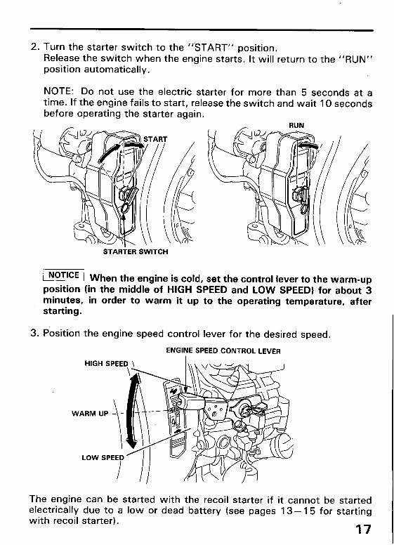
2. Turn the starter switch to the “‘START” position. Release the switch when the engine starts. It will return to the “RUN” position automatically.
NOTE: Do not use the electric starter for more than 5 seconds at a time. If the engine fails to start, release the switch and wait 10 seconds before operating the starter again.
RUN
STARTER SWITCH
@!@ When th e engine is cold, set the control lever to the warm-up position (in the middle of HIGH SPEED and LOW SPEED) for about 3 minutes, in order to warm it up to the operating temperature, after starting.
3. Position the engine speed control lever for the desired speed.
ENGINE SPEED CONTROL LEVER
LOW SPEED
The engine can be started with the recoil starter if it cannot be started electrically due to a low or dead battery (see pages 13- 15 for starting with recoil starter).
17

6. STOPPING THE ENGINE
Stopping the engine
( Attempting to stop the engine with the decompression lever will damage the engine (electric start models only).
1. (Dual lever type) a. Move the stop lever down to the “STOP” position.
ENGINE STOP ’ STOP LEVER
(Single lever type) b. Move the engine speed control lever down to the STOP position.
ENGINE STOP ENGINE SPEED CONTROL LEVER
I 18.

2. (Electric start model) After the engine stops, move the starter switch to the “OFF” position.
STARTER SWITCH

7. MAINTENANCE
Periodic maintenance and adjustment are necessary to keep the engine in good operating condition. Perform the service and inspection scheduled in the following table.
Shut off the engine before performing any maintenance. If the engine must be run, make sure the area is well ventilated.
m The exhaust contains poisonous carbon monoxide gas; ex- posure can cause loss of consciousness and may lead to death.
POTICE 1 Us e only genuine HONDA parts or their equivalent. The use of replacement parts which are not of equivalent quality may damage the engine.
REGULAR SERVICE PERIOD FIRST EVERY EVERY EVERY EVERY EVERY
I\ Perform at every indicated month or operating hour in-
EACH MONTH 3 MONTHS 6 MyRTHS YEAR USE OR OR OR
* ‘;iRS 3 ‘6;“” REMARKS
.EM terval. whichever comes first. 20 HRS 50 HRS 100 HRS 300HRS 500HRS 1OOOHRS \
lgine oil Check level 0 _._.....__...._____________......__~~..~~~~~~~~~~~~~.......~~...~~~~~~~~~~~~ ------~------- Change 0 0
lgine oil filter Cl*Xl 0
,r Cleaner Check 0 Vet type1
_...---____._______.._____....-........---------.------------.------------- -------------- Cl*all (Foam element O(l) (31 CNllY) _-.--..--.--._____............---.-----------.---------------- --------------- -
Change I 1 0 1 I I ,ark arrester ClC?atl 1 0 1 1 (41 ._I ‘:#A__ P.^--^ I I I I I I I n19, I
L
Fuel ,,,~LI, b,ll(lly.s .-a-,
Injection nozzle Check O(2) 1
Fuel tank Check 0 I I (Water drain) ~~,-~~n-.--~~~‘~~......‘....--~~’~~~~~~~......---------------..........---------------------.------.
01-. , I Fuel line I-hr.,-k I
ii -,---- .-.-.-__--.-. t 1 -..-“”
(Replace if WG%.%3ry)
Every 2 years
8” I I I I I Combusta chamber, valves and
Clean-lap
pistion rings
Valve clearance Check-Adjust
All fasteners (for tightnessl: CYlinder head Check-Retighten bolts, fuel System etc.
. .
O(2)
O(2)
O(21
NOTE ,I, Serwce more trequently wnen use,, I” (~“sry areas. (21 These items should be serviced by an authorized Honda dealer, unless the owner has the proper tools and is mechanically
proficient. See the Honda Shop Manual. (3) The color of paper element is red. Also, it is marked with “Wet”. 14) Equipped type only.
1 20
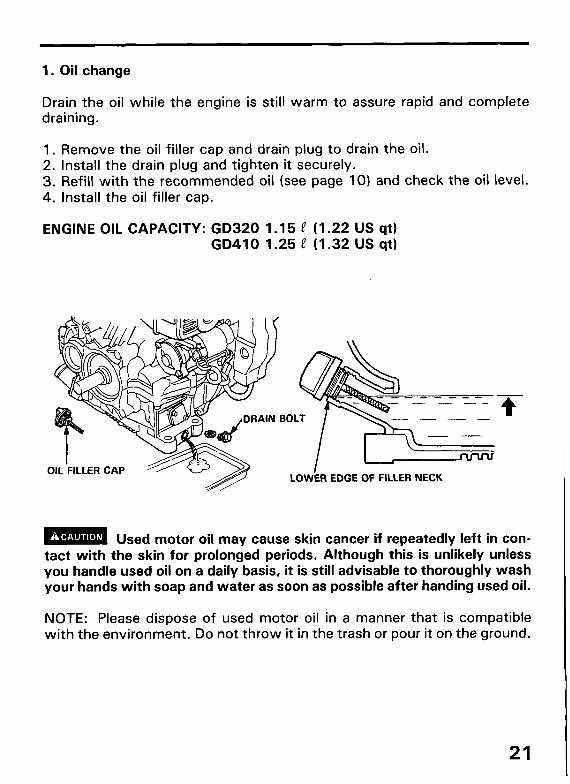
1. Oil change
Drain the oil while the engine is still warm to assure rapid and complete draining.
1. Remove the oil filler cap and drain plug to drain the oil. 2. Install the drain plug and tighten it securely. 3. Refill with the recommended oil (see page IO) and check the oil level. 4. Install the oil filler cap.
ENGINE OIL CAPACITY: GD320 1.15 e (1.22 US qt) GD410 1.25 P (I .32 US qt)
m Used motor oil may cause skin cancer if repeatedly left in con- tact with the skin for prolonged periods. Although this is unlikely unless you handle used oil on a daily basis, it is still advisable to thoroughly wash your hands with soap and water as soon as possible after handing used oil.
NOTE: Please dispose of used motor oil in a manner that is compatible with the environment. Do not throw it in the trash or pour it on the ground.
21

2. Engine oil filter service
m A clogged or restricted oil filter can cause serious engine damage.
The service intervals shown in the Maintenance Schedule on page 20 are the minimum. It may be necessary to service the oil filter more often than indicated. Severity of use, oil quality, climate, etc. all affect the oil filter service interval.
(Cleaning) 1. Drain oil from the engine (see page 21). 2. Remove the oil filter from the engine by removing the two 6 mm bolts. 3. Wash the filter in nonflammable or high flash point slovent. Allow the
filter to dry thoroughly. 4. Reinstall the filter and filter cover and the two 6 mm bolts. 5. Tighten the bolts securely. 6. Fill the crankcase to the proper level with the recommended oil.
NOTE: l Take care not to damage the filter mesh when servicing the filter. l Replace the filter with a new one if there are holes or tears in the filter
mesh.
6mm
I 22
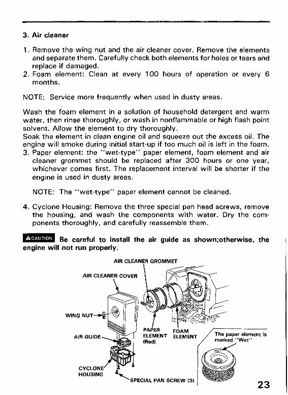
3. Air cleaner
1. Remove the wing nut and the air cleaner cover. Remove the elements and separate them. Carefully check both elements for holes or tears and replace if damaged.
2. Foam element: Clean at every 100 hours of operation or every 6 months.
NOTE: Service more frequently when used in dusty areas.
Wash the foam element in a solution of household detergent and warm water, then rinse thoroughly, or wash in nonflammable or high flash point solvent. Allow the element to dry thoroughly. Soak the element in clean engine oil and squeeze out the excess oil. The engine will smoke during initial start-up if too much oil is left in the foam. 3. Paper element: the “wet-type” paper element, foam element and air
cleaner grommet should be replaced after 300 hours or one year, whichever comes first. The replacement interval will be shorter if the engine is used in dusty areas.
NOTE: The “wet-type” paper element cannot be cleaned.
4. Cyclone Housing: Remove the three special pan head screws, remove the housing, and wash the components with water. Dry the com- ponents thoroughly, and carefully reassemble them.
w Be careful to install the air guide as shown;otherwise, the engine will not run properly.
AIR CLEANER GROMMET
AIR CLEANER COVER
WING NUT
F6AM ELEMENT
PACER ELEMENT (Red)
SPECIAL PAN SCREW (3) 23

4. Draining water from the fuel tank
It is normal for water to collect in the bottom of the fuel tank. It is impor- tant to drain this water regularly.
L!!%!?. Failure to drain water from the fuel tank can lead to engine damage.
(Draining) 1. Loosen the water drain bolt about 2-3 turns to uncover the water drain
hole.
m To prevent fuel spillage, do not unscrew the drain bolt more than necessary to uncover the water drain hole provided in the bottom of the fuel tank.
2. Continue to drain the tank through the water drain hole until fuel starts to flow out.
3. Tighten the drain bolt securely.
DRAIN BOLT
WATER DRAIN HOLE
I 24

5. Spark arrester maintenance (Equipped type only)
m The muffler becomes very hot during operation and remains hot for a while after the engine stops. Be careful not to touch the muffler while it is hot. Allow it to cool before proceeding.
The spark arrester must be serviced every 100 hours to maintain its efficiency.
1. Remove the three 8 mm nuts and 8 mm bolt and remove the muffler. 2. Remove the three 8 mm nuts and remove the spark arrester (be careful
not to damage the spark arrester screen). 3. Use a wire brush to remove carbon deposits from the spark arrester
screen.
NOTE: Inspect the spark arrester screen for holes or tears. Replace it if it is damaged.
SPARK ARRESTER
8 mm NUTS (
EXHkJST PIPE
8 mm NUTS (3)
MUFFLER 8 mm BOLT
25

8. TRANSPORTING/STORAGE
Before storing the unit for an extended period: 1. Be sure the storage area is free of excessive humidity and dust. 2. Drain fuel into an approved gasoline container by removing the drain
bolt at the bottom of fuel tank.
m Diesel fuel is extremely flammable and is explosive under cer- tain conditions. Do not smoke or allow flames or sparks in the area.
FUEL DRAIN BOLT
3. Change the engine oil (see page 21). 4. Close the valves to help prevent internal engine corrosion. See instruc-
tions below.
l Manual start type: Pull the starter grip until you feel resistance, and then continue to pull slowly until the “A” mark on the starter pulley is at the top. Return the starter grip to its original position.
l Electric start model: Pull the starter grip slowly until you feel strong resistance. Lift the decompression lever, and continue to pull the grip just until the ” A" mark on the starter pulley is at the top. At that point, close the decompression lever and return the starter grip to its original PO sition.
5. Clean the entire engine thoroughly, put a protective cover over it, and store it in a place that is free of dust and moisture.
1 26

9. TROUBLESHOOTING
Engine will not start:
l Is the starting procedure being followed carefully? l Is there fuel in the tank? l Is the stop switch lever in the ON position? (Dual lever type) l Is the engine speed control lever in the correct position? (Single lever
type)

10. SPECIFICATIONS
1 Dimensions GD320 GD410
Description code 1 GPB GPA
lQIWIVIQl P V
Length
Width mm 405 I
405 in (I 5.9) (I 5.9) I
Height
Dry weight
mm in
kg
470 490 (I 8.5) (19.3)
lb (104:.8) (I 15940,
Engine
Engine type 4-stroke, overhead valve, 1 cylinder diesel
Displacement 317 cm3 (19.3 cu in) 411 cm3 (25.1 cu in)
[Bore x Stroke] [76 x 70 mm [82 x 78 mm (3.0 x 2.8 in)] (3.2 x 3.1 in)1
Max. output 5.2 KW/3600 rpm 6.7 KW/3600 rpm (7 HP/3600 rpm) (9 HP/3600 rpm)
Max. torque 15.7 N-m {I .6 kg-m 20.6 N.m (2.1 kg-m
(I 1.6 ft-lb)}/2500 rpm (I 5.2 ft-lb)}/2500 rpm
Engine oil capacity 1.15 e (1.22 USqt) 1.25 P (1.32 US qt)
Fuel consumption 180 g/psh
Cooling system Forced air
Fuel injection pump PFRI KX made by DKKC
Fuel Diesel
Engine start system Recoil starter, Recoil or electric starter
PTO shaft rotation Counterclockwise
Rated output 4.4 KW/3600 rpm 5.9 KW/3600 rpm (6 HP/3600 rpm) (8 HP/3600 rpm)
Compression ratio 20 : 1 20 : 1
Fuel tank capacity 4.6 t (4.9 US qt)
Injection nozzle DLLA-P made by DKKC - . . -. . . . . . Combustlon SyStefT3 1 uirect Injection system
NOTE: Specifications are subject to change without notice. 28

‘I 1. WARRANTY SERVICE
Owner Satisfaction
Your satisfaction and goodwill are important to your dealer and to us. All Honda warranty details are explained in the Distributor’s Limited Warran- ty. Warranty service is available at any dealership displaying the Honda Power Equipment Engines sign. To locate dealers in your area, look in the yellow pages of your telephone directory under Gasoline Engines, Garden & Lawn Equipment & Supplies, Lawn Mowers, etc.
Normally, any problem concerning the engine will be handled by the dealer’s service department. If you have a warranty problem that has not been handled to your satisfaction, we suggest you take the following action: l Discuss your problem with a member of dealership management. Often
complaints can be quickly resolved at that level. If the problem has already been reviewed with the Service Manager, contact the owner of the dealership or the General Manager.
l If your problem still has not been resolved to your satisfaction, contact:
American Honda Motor Co., Inc. P.O. Box 100021 Duluth, Georgia 30136-942 1 Telephone: (404) 497-6400
We will need the following information in order to assist you: - Your name, address, and telephone number - Engine model and serial number - Date of purchase - Dealer name and address - Product or equipment in which the engine is installed. - Nature of the problem
After reviewing all the facts involved, you will be advised of what action can be taken. Please bear in mind that your problem will likely be resolved at the dealership, using the dealer’s facilities, equipment, and personnel, so it is very important that your initial contact be with the dealer.
Your purchase of a Honda engine is greatly appreciated by both your dealer and American Honda Motor Co., Inc. We want to assist you in every way possible to assure your complete satisfaction with your purchase.
29

Current customer service contact information: Servicing dealership personnel are trained professionals. They should be able to answer any question you may have. If you encounter a problem that your dealer does not solve to your satisfaction, please discuss it with the dealership's management. The Service Manager, General Manager, or Owner can help. Almost all problems are solved in this way.
United States, Puerto Rico, and U.S. Virgin Islands: If you are dissatisfied with the decision made by the dealership's management, contact the Honda Regional Engine Distributor for your area (www.honda-engines.com/dea.htm).
If you are still dissatisfied after speaking with the Regional Engine Distributor, you may contact the Honda Office as shown.
American Honda Motor Co., Inc. Power Equipment Division Customer Relations Office 4900 Marconi Drive Alpharetta, GA 30005-8847
Or telephone: (770) 497-6400 M-F, 8:30 am - 7:00 pm EST
When you write or call, please provide the following information:
• Equipment manufacturer's name and model number that the engine is mounted on
• Engine model, serial number, and type
• Name of the dealer who sold the engine to you
• Name, address, and contact person of the dealer who services your engine
• Date of purchase
• Your name, address, and telephone number
• A detailed description of the problem

MEMO
I 30

MEMO
I
31 ’

MEMO
32