REMOTE ENGINE STARTER MZ360340EX …faq.out-club.ru/download/common/acc/MZ360340EX.pdfREMOTE ENGINE...
21
REMOTE ENGINE STARTER MZ360340EX INSTALLATION INSTRUCTIONS Applicable Models RVR (10MY-) Thank you for purchasing the Mitsubishi Genuine Accessory. To install and use the product correctly with proper knowledge of it, read this publication carefully. Keep this publication for reference when maintenance is required. - This publication gives precautionary instructions in the boxes titled as follows. Read through these instructions thoroughly. - Failure to follow these instructions not only prevents the product from working properly but may lead to trouble with the vehicle. Be sure to follow all instructions carefully. - If there is anything unclear about the installation, handling and/or usage of the product, contact your Mitsubishi Motors dealer for clarification. - Mitsubishi Motors Corporation is not responsible for any defects or difficulties caused by or resulting from the failure to follow given instructions. - We recommend you to have the installation performed at an authorized Mitsubishi Motors dealer. Caution ! This system is exclusively for automatic transmission vehicles. Never install this system on the manual transmission vehicles. Warning ! Describes precautions that should be observed in order to prevent serious injury or death to the user. Describes precautions that should be observed in order to prevent injury or damage to the vehicle or its components, which may occur if sufficient care is not taken. Provides additional information that facilitates installation work. Note ZZ100-00410-0 10, 7 To the dealer: Be sure that the customer receives this publication. Attention Warning !
Transcript of REMOTE ENGINE STARTER MZ360340EX …faq.out-club.ru/download/common/acc/MZ360340EX.pdfREMOTE ENGINE...

REMOTE ENGINE STARTER MZ360340EX
INSTALLATION INSTRUCTIONS
Applicable Models RVR (10MY-)
Thank you for purchasing the Mitsubishi Genuine Accessory.
To install and use the product correctly with proper knowledge of it, read this publication carefully.
Keep this publication for reference when maintenance is required.
- This publication gives precautionary instructions in the boxes titled as follows.
Read through these instructions thoroughly.
- Failure to follow these instructions not only prevents the product from working properly but may lead to trouble
with the vehicle. Be sure to follow all instructions carefully.
- If there is anything unclear about the installation, handling and/or usage of the product, contact your Mitsubishi
Motors dealer for clarification.
- Mitsubishi Motors Corporation is not responsible for any defects or difficulties caused by or resulting from the
failure to follow given instructions.
- We recommend you to have the installation performed at an authorized Mitsubishi Motors dealer.
Caution !
This system is exclusively for automatic transmission vehicles. Never install this system on the manual transmission vehicles.
Warning !
Describes precautions that should be observed in order to prevent serious injury or death to the user.
Describes precautions that should be observed in order to prevent injury or damage
to the vehicle or its components, which may occur if sufficient care is not taken.
Provides additional information that facilitates installation work. Note
ZZ100-00410-0
10, 7
To the dealer: Be sure that the customer receives this publication.
Attention
Warning !

- 2 -
■ TOOLS (Make the following tools ready for use.)
Socket wrench (10mm) Extension bar Phillips screwdriver (medium) Scissors Cutting pliers Trim remover Scale Vinyl tape Multimeter
■ COMPONENTS (Make sure that all of the following components were included in the kit.) ① Electronic control unit:1
②Control unit:1
③Antenna unit:1
④Harness:1
⑤Urethane sheet:1
⑥Corrugated tube:1
⑦Tie-wrap:13
⑧Protective sheet:1
⑨Remote controller:1
⑩Installation Instructions:1 (this document)
⑪Owner’s Manual:1
■ PRECAUTIONS
- Be sure to apply the parking brake securely. Remove the ignition key from the key cylinder.
- Disconnecting the (–) cable from the battery causes the radio and audio presets, the clock, etc. to lose their
memory. Record the contents of the memory before disconnecting the battery (–) cable to allow you to reprogram
the radio presets after the installation is completed.
- Be sure to connect the connectors securely.
- At positions where the harness may interfere with other vehicle parts, take appropriate measures such as
winding vinyl tape over the harness or fixing the harness using tie-wraps to prevent it from damage and dangling.
- To prevent the cut edges of tie wraps causing injury, do the following:
- Wind the tie wrap with its protruding part pointing downward (so that its cut end points downward).
- Cut off the excess tie wrap close to the head. Do not cut at an angle.

- 3 -
- Be sure to disconnect the negative terminal cable from the battery.
- Loosen or tighten bolts and nuts using tools that match their sizes.
- Use a Phillips screwdriver that fits the recess in the head of the screw being loosened or tightened.
- To remove plastic parts, use a trim remover.
- When disconnecting connectors, first unlock them, then separate the connectors by pulling on themselves, not on cables.
- When connecting connectors, push them against each other until the lock clicks.
- Do not pull on wiring harnesses strongly.
- Do not let harnesses be pinched between parts.
- Route the harness away from hot components such as the engine and radiator.
- Protect the harness from sharp edges by covering the edges with tape or other suitable materials.
- Apply sealant to grommets at portions where the harness run through.
- Do not fasten the harness to brake pipes or high pressure air conditioner pipes.
- Fasten the additional harness to an existing vehicle harness using tape or tie wraps.
- Bind up extra length of the harness using a tie wrap.
- If one tie wrap is too short, use two connected together.
- Check the product and wiring for installed condition before connecting the cable to the battery.
- Check the installed product for function. Also check lamps, horn, wipers, etc. for proper operation.
Before installation When installing or removing parts
Wiring
Clamping harness After installation
click!
click!
click!
Beep

- 4 -
INSTALLATION PROCEDURES FOR RVR A. PREPARATORY WORK
1) Confirm that the ignition key is removed and all the
electrical switches are off. Then disconnect the battery(–) cable from the battery.
2) Remove the following parts in accordance with the workshop manual. - Side lower panel - Front pillar trim, driver’s side - Front scuff plate, driver’s side - Cowl side trim, driver’s side - Side cover, driver’s side
Side lower panel Front pillar trim
Cowl side trim
Front scuff plate
Side cover
Check

- 5 -
B. ROUTING THE HARNESS 1) Route the harness ④ and the antenna unit ③ as shown in the drawing.
- Harness ④: Route from the ETACS-ECU along the floor harness under the scuff plate to the underside of the driver’s
seat. - Antenna unit ③:
Wind the urethane sheet ⑤ around the antenna unit for protection. Then route the cable of the antenna unit ③ to the underside of the driver’s seat.
Harness layout
③Antenna unit
A
B
C
E
4-pin connector of the harness ④
②Control unit
Antenna jack of the antenna unit ③
8-pin connector of the harness ④
Fuse holder of the harness ④
ETACS-ECU
Route the harness ④ and the cable of the antenna unit ③ along the floor harness to the underside of the driver’s seat.
Ground terminal of the harness ④
D12-pin connector of the harness ④
13-pin connector of the harness ④
Check
①Electronic control unit

- 6 -
C. INSTALLING THE ANTENNA UNIT
1) Cut the urethane sheet ⑤into the following dimensions. A:35 x 140 mm (2 pieces) B:70 x 20 mm (5 pieces)
2) Wrap the two pieces of urethane sheet A ⑤ around
the cable of the antenna unit ③.
3) Pass the cable of the antenna unit ③ into the
backside of the instrument panel at the bottom of the front pillar.
4) Position the antenna unit ③ along the roof harness and bind them using the three pieces of urethane sheet B ⑤.
View A
140mm
20mm x 5
35mm
35mm
100mm
300mm
A
A B B B B B
⑤Urethane sheet A
140mm
③Antenna unit
Cable of the antenna unit ③
Tube
Approx. 5mm
Wrap around the end of the tube.
Cable
140mm
Check
③Antenna unit
Pass into the backside of theinstrument panel.
⑤Urethane sheet B Instrument panel
Roof harness
Align the point of the antenna with the point of the clip.

- 7 -
D. ROUTING UNDER THE INSTRUMENT PANEL
1) Route the cable of the antenna unit ③ along the roof harness at the backside of the instrument panel and bundle them using the tie-wraps ⑦ as shown in the drawing. 2) Connect the 4-pin connector of the harness ④ to
the unused 4-pin connector on the ETACS-ECU securely.
3) Secure the fuse holder of the harness ④ on the
crossmember side bracket in the direction shown in Detail b using the tie-wrap ⑦.
4) To prevent damage of the harness ④ by the
brackets around the hood lock release handle, cover the harness ④ and the cable of the antenna unit ③ with the corrugated tube ⑥ as shown in the drawing. Wind the urethane sheet B ⑤ around each end of the corrugated tube to fix the tube in position.
5) Route the corrugated tube ⑥ along the floor
harness and bundle them using the tie-wrap ⑦. 6) Tighten the ground terminal of the harness ④ to the
vehicle’s ground point securely.
7) Route the harness ④ and the cable of the antenna
unit ③ along the floor harness to the underside of the driver’s seat and bundle them using the tie-wraps ⑦.
View B
Connect the ground terminal of the harness④ to the ground point.
Fuse holder of the harness ④
Cable of the antenna unit ③
ETACS-ECU
⑤Urethane sheet B
⑥Corrugated tube
b
Hood lock release handle
Floor harness
Harness ④ and the cable of the antenna unit ③
⑦Tie-wrap
Roof harness
⑦Tie-wrap
4-pin connector of the harness ④
⑦Tie-wrap ⑦Tie-wrap
Detail b Crossmember side bracket
Instrument harness
Wrap and fix harness ④ toinstrument harness using tie-wrap ⑦.
⑦Tie-wrap
Fuse holder
Refer to the workshop manual for the ground
bolts tightening torque.
⑦Tie-wrap
Harness ④ and the cable of the antenna unit ③
Floor harness
Slit on the floor carpet
⑦Tie-wrap
Front seat anchor coverView C
Position the harness and cable so as not to be
pinched by the scuff plate mounting clips.
Note
When routing the harness and cable from under
the floor carpet to the underside of the driver’s
seat, releasing the driver’s seat fasteners will
facilitate the work.
Note
Caution !
Check

- 8 -
E. ROUTING UNDER THE DRIVER’S SEAT
1) Cut off a 25 x 50 mm sheet from the protective sheet ⑧. Attach it on the electronic control unit ① as shown in the drawing.
2) Secure the electronic control unit ①, control unit ②
and the harness ④ to the connector bracket under the driver’s seat using tie-wrap ⑦ as shown in the drawing.
- The electronic control unit ① should be aligned with the front end of the connector bracket.
- Locate these units where they would not interfere with other parts when the seat is moved forward/reverse or upward/downward.
3) Connect the antenna jack of the antenna unit ③ to
the electronic control unit ①. 4) Secure the harness ④ and the cable of the antenna
unit ③ with the floor harness using the tie-wrap ⑦ while taking care not to interfere the harnesses with the vehicle’s brackets. In addition, bundle the excess lengths of there harness ④ and the cable ③ together in a proper way.
50mm
25mm
⑧Protective sheet
①Electronic control unit
②Control unit
①Electronic control unit
Antenna jack of the antenna unit ③
8-pin connector of the harness ④
⑦Tie-wrap
Connector bracket
Floor harness Harness ④ and cable of the antenna unit ③
View D
⑦Tie-wrap
Raising the seat cushion will facilitate the work.
Note
②Control unit
①Electronic control unit
⑦Tie-wrap
Rear of vehicle Front of vehicle
Securing the electronic control unit ① and the control unit ②
Connector bracket
Align with the front end of the connector bracket.
Secure the harness ④ also with the tie-wrap ⑦

- 9 -
5) Connect the 8-pin connector of the harness ④ to
the control unit ② securely. 6) Connect the 12-pin connector and the 13-pin
connector of harness ④ to the electronic control unit ① securely.
7) After connection, confirm that the harness ④ does
not interfere with any part of the seat while moving the seat forward/reverse and upward/downward.
F. CHECKING AFTER INSTALLATION 1) Check that all the harnesses are connected correctly while referring to the wiring diagram.
2) Check that all the connectors are connected securely.
3) Fix the harnesses properly to prevent them from interference and dangling using the tie-wraps ⑦ and vinyl
tape.
G. REGISTRATION AND OPERATION CHECK
1) Connect the battery (-) cable.
2) Perform the registration and operation check in accordance with “REGISTRATION AND OPERATION CHECK
PROCEDURES” (Page 10).
H. REINSTALLATION 1) Reinstall the removed parts to the vehicle in accordance with the workshop manual.
2) Reprogram the radio and audio memories and adjust the clock. For the reprogramming procedure, refer to the
owner’s manual.
View E
Check
②Control unit
Connector bracket
①Electronic control unit
8-pin connector of the harness ④
13-pin connector of the harness ④ 12-pin connector of
the harness ④
- Be careful not to pinch the harnesses or damage the parts.
- Refer to the workshop manual for the reinstallation of the parts.
- Refer to the workshop manual for the tightening torque of each bolt.
Caution !
Check
Check
Check

- 10 -
REGISTRATION AND OPERATION CHECK PROCEDURES
(1) Operation check of remote controller
Perform the operation check in the following procedure.
1) Perform the engine start operation.
①Push Function SW short once. .
②While Start Mark is blinking,
push Start SW until sounding Buzzer.
Go to
Troubleshooting A.
OK NG
- Before starting the work, refer to the drawing in the owner’s manual to confirm the name and use of the controls on the remote controller. - Release the Switch Lock referring to the drawing in the owner’s manual if the Switch Lock Mark ( ) lights when the switch of the remote controller is pushed. - Replace the battery for the new article referring to the owner’s manual if the Battery Mark ( ) lights when the switch of the remote controller is pushed.
Beep
!
Never perform the registration and operation check procedures simultaneously on some vehicles to
prevent duplicated registration.
Caution !
!
- The remote controller should be checked with the (-) terminal of the vehicle’s battery disconnected.
- For how to install batteries, refer to the owner’s manual.
Caution !
Note
Check
→ Start Mark blinks approx. 3 seconds.
→ Buzzer sounds, and the idling
time, Transmission, Start Mark
lights approx. 3 seconds.
In case idling time is 10 minutes.
In case idling time is 30 minutes.

- 11 -
2) Perform the engine stop operation.
(2) Registration of the remote controller
Connect the (-) terminal of the vehicle's battery and perform the registration in the following procedure.
Beep
①Push Stop SW for 1 seconds or more.
→ Buzzer sounds, and
Transmission, Stop Mark
lights approx. 3 seconds.
Go to
Troubleshooting A.
NG
Do not step on the brake pedal when operating that pushes the engine switch on vehicles with keyless
operation system : the engine switch is a push type.
Check
-The engine starter cannot function unless the remote controller is registered correctly.
- This procedure requires the keyless-entry key or keyless operation key registered to the vehicle.
- Some steps of this procedure must be performed within the limited time. Be sure to understand this
procedure fully before starting the work.
If the required operation have not finished in a specified time, retry the registration procedure from the
beginning.
The step that has a time limit is shown by a black arrow " ".
- The remote controller will not be registered if the procedure is not performed in the correct way. In such
case, disconnect the (-) terminal of the vehicle's battery once and then retry the registration procedure
from the beginning.
Caution !
Caution !
1) Set the vehicle in the following condition.
- Close all the doors (including backdoor and trunk lid) and hood.
(The worker should get in the vehicle.)
- Remove the ignition key from the ignition key cylinder.
On vehicles with keyless operation system : the engine switch is a rotary type.
Set the ignition knob to LOCK (OFF) position and remove the ignition knob cap.
On vehicles with keyless operation system : the engine switch is a push type.
Set the state of LOCK(OFF) (The indicator of the switch is turned off).

- 12 -
2) Insert the ignition key into the key cylinder. Turn the key from LOCK (OFF) to ACC, and wait for 3 to 5 seconds.
On vehicles with keyless operation system : the engine switch is a rotary type.
Insert the emergency key into the ignition knob.
Turn the ignition knob from LOCK(OFF) to ACC, and wait for 3 to 5 seconds.
On vehicles with keyless operation system : the engine switch is a push type.
Push the engine switch once, set to the ACC state(The indicator of the switch lights to the
orange color), and wait for 3 to 5 seconds.
3) Return the key from ACC to LOCK (OFF).
On vehicles with keyless operation system : the engine switch is a rotary type.
Return the ignition knob from ACC to LOCK (OFF).
On vehicles with keyless operation system : the engine switch is a push type.
Push the engine switch twice, set to the LOCK(OFF) state(The indicator of the switch is
turned off).
4) Within 10 seconds after the operation in the above step 3), turn the key from LOCK
(OFF) to ACC to LOCK (OFF) repeatedly 4 times.
On vehicles with keyless operation system : the engine switch is a rotary type.
Within 10 seconds after the operation in the above step 3), turn the ignition knob
from LOCK (OFF) to ACC to LOCK (OFF) repeatedly 4 times.
On vehicles with keyless operation system : the engine switch is a push type.
Within 10 seconds after the operation in the above step 3), push the engine switch
12 times. When the key (or knob) is finally returned to the LOCK(OFF) position after the above operation, the buzzer of the ECU beeps once. If the buzzer sounds once, remove the key.
- In case of “On vehicles with keyless operation system : the engine switch is a push type”, the transition of LOCK (OFF) to ACC to IG to LOCK (OFF) state will be repeated 4 times by pushing the engine switch from the LOCK(OFF) state (The indicator of the switch is turned off) 12 times. After the engine switch is pushed 12 times, the state will be the LOCK(OFF) state (The indicator of the switch is turned off). If the state is not LOCK(OFF) state (The indicator of the switch is turned off) after pushing it 12 times, disconnect the (-) terminal of the vehicle's battery once and reconnect it, and then retry the registration procedure from the beginning.
Note
NG Go to
Troubleshooting B.
OK

- 13 -
5) Within 5 seconds after the operation in the above step 4), push three switches
(Function Switch, Start Switch, and Stop Switch) on the right side of the remote
controller at the same time for 1 second or more.
The buzzer of the remote controller sounds when pushing for 1 second or more,
and the Start Mark and Stop Mark begin blinking.
OK
Faulty remote
controller
NG
Beep
Pushes at the same timefor 1 second or more
While the Start Mark and Stop Mark of the remote controller is blinking (about 20
seconds), perform the following operations 6) and 7).
6) Insert the ignition key into the key cylinder and turn the key from LOCK (OFF) to ACC
to LOCK (OFF), and remove the key.
On vehicles with keyless operation system : the engine switch is a rotary type.
Insert the emergency key into the ignition knob and turn the knob from LOCK(OFF)
to ACC to LOCK(OFF), and remove the emergency key.
On vehicles with keyless operation system : the engine switch is a push type.
Push the engine switch 3 times for the state transition of LOCK(OFF) to ACC to IG
to LOCK(OFF).
When the key (or knob) is returned to the LOCK(OFF) position, the buzzer of the ECU
will beep once.
7) Perform the engine stop operation by the remote controller.
If the remote controller is operated correctly, the buzzer of the ECU will beep twice.
NG Go to
Troubleshooting B.
Beep
Pushes the Stop Switchfor 1 second or more
OK
OK

- 14 -
If any switch except the engine stop switch is pushed in the above step 7), the registration operation is
discontinued. (The Start Mark and Stop Mark stop blinking, and all the marks on display are turned off.)
If the registration operation is discontinued by misoperation, disconnect the (-) terminal of the vehicle's
battery once and reconnect it, and then retry the registration procedure from the beginning.
Note
8) Within 10 seconds after the sound of the buzzer in the above step 7), perform
the following operations.
- Using the keyless-entry key (or keyless operation key) registered to the
vehicle, press the door unlock button 3 times successively.
After the above operation, the door locks should automatically lock and unlock
once and then, after several seconds, lock and unlock again.
Registration is completed
NG
OK
Go to
Troubleshooting C.
OK

- 15 -
(3) Operation check
Perform the operation check in the following procedure while referring to the owner's manual.
Check4) Failsafe function check
1) Set the vehicle in the following conditions.
- Set the shift lever in the "P" position and apply the parking brake.
- Remove the ignition key from the key cylinder.
On vehicles with keyless operation system : the engine switch is a rotary type.
Set the ignition knob to LOCK (OFF) position and remove the ignition knob cap.
On vehicles with keyless operation system : the engine switch is a push type.
Set the state of LOCK(OFF) (The indicator of the switch is turned off).
- Close all the doors (including backdoor and trunk lid) and hood.
2) Check the engine start operation
OK
NG
OK
Check
NG
The engine starts.
Perform the engine start operation. Go to
Troubleshooting A.
3) Check the engine stop operation.
OK
Perform the engine stop operation.
The engine stops.
OK
NG
Check
Perform the engine start operation with a door opened. → The engine
would not start.
NG
NG
OK
OK
Operation check completed.
Close all doors, insert the ignition key into the key cylinder, and perform
the engine start operation. → The engine would not start.
Check the vehicle.
Check the vehicle.
The Control unit or the vehicle is faulty. Check the vehicle.
The Control unit or the vehicle is faulty. Check the vehicle.

- 16 -
Circuit Diagram
- 17 -
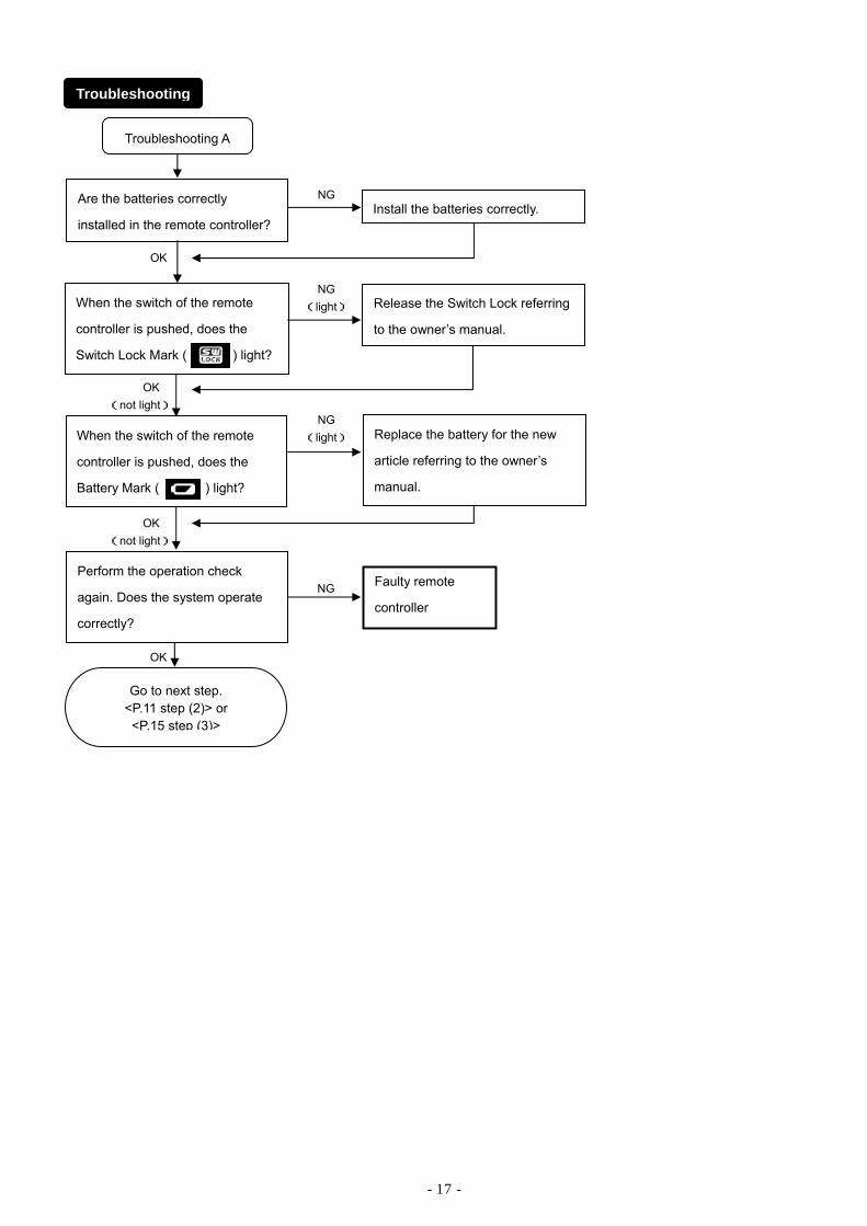
When the switch of the remote
controller is pushed, does the
Battery Mark ( ) light?
Troubleshooting A
Are the batteries correctly
installed in the remote controller? Install the batteries correctly.
Replace the battery for the new
article referring to the owner’s
manual.
NG
OK
Go to next step. <P.11 step (2)> or <P.15 step (3)>
Faulty remote
controller
Perform the operation check
again. Does the system operate
correctly?
NG
OK
Troubleshooting
When the switch of the remote
controller is pushed, does the
Switch Lock Mark ( ) light?
Release the Switch Lock referring
to the owner’s manual.
NG (light)
OK (not light)
OK (not light)
NG (light)

- 18 -
Troubleshooting B
Check that each terminal of the
connectors is in good condition
according to 1. Checking
connector terminals in “Checking
Harnesses”.
Check the continuity of the
harnesses according to 2.
Checking continuity in “Checking
Harnesses”.
NG
OK
NG
Disconnect the (-) terminal of the
battery. Then reconnect the
battery (-) terminal and perform
the registration procedure again.
OK
With the harness connected only
to the ETACS-ECU, check the
terminals No. 5, 6, and 8 are
within specification according to
1. Checking connector terminals
in “Checking Harnesses”.
OK
Faulty control unit, electronic
control unit, or remote controller.
Are all the connectors connected
securely? Connect securely.
NG
OK
NG
Check the vehicle.NG
OK
Faulty harness
Are both two fuses (5A) of the
engine starter harness in good
condition?
Remove the cause of the blown
fuse and replace the fuse(s).
NG
OK
Go to next step. <P.11 step (2)>
- 19 -
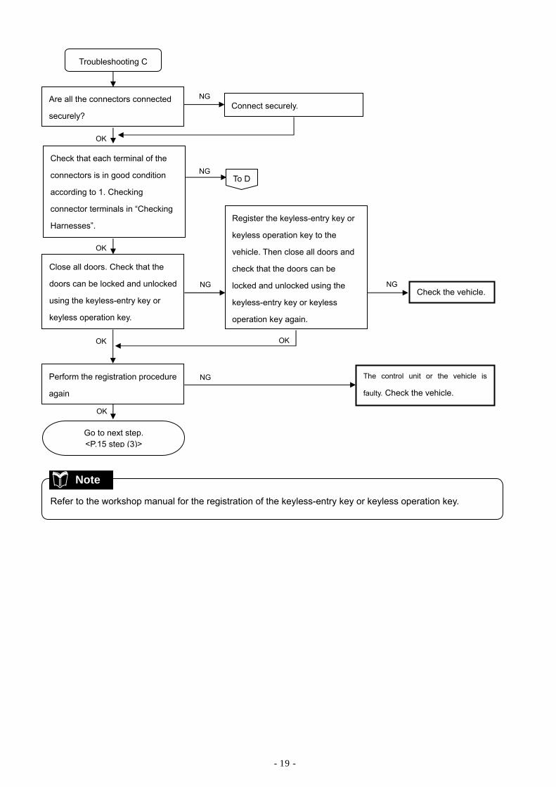
Troubleshooting C
NG
NG Perform the registration procedure
again
OK
OK
Are all the connectors connected
securely? Connect securely.
NG
OK
Close all doors. Check that the
doors can be locked and unlocked
using the keyless-entry key or
keyless operation key.
To D
NG
Register the keyless-entry key or
keyless operation key to the
vehicle. Then close all doors and
check that the doors can be
locked and unlocked using the
keyless-entry key or keyless
operation key again.
OK OK
NG Check the vehicle.
Refer to the workshop manual for the registration of the keyless-entry key or keyless operation key.
Check that each terminal of the
connectors is in good condition
according to 1. Checking
connector terminals in “Checking
Harnesses”.
The control unit or the vehicle is
faulty. Check the vehicle.
Note
Go to next step. <P.15 step (3)>

- 20 -
OK
NG
OK
As the result of the 1. Checking
connector terminals in “Checking
Harnesses”, only the No. 2
terminal of the connector ① is
out of specification.
NO
YES
With the harness connected only
to the ETACS-ECU, check the
terminals NO, 5, 6 and 8 are
within specification according to
1. Checking connector terminals
in “Checking Harnesses”.
D
Check the continuity of the
harnesses according to 2.
Checking continuity in “Checking
Harnesses”.
NG Faulty harness
Faulty control unit or electronic
control unit
Check the vehicle.
Faulty control unit or electronic
control unit

- 21 -
1. Checking connector terminals
While referring to the circuit diagram, check each terminals of the connector ① (8-pin, black) connected to the control
unit in accordance with the following table using a multimeter.
Connector
No.
Terminal
No.
Item Check condition Specification Check
1 Voltage between the terminal
and the body ground
Any time 10 to 14V
Within approx. 4 seconds
after performing the engine
stop operation in step 7) of
the registration procedure.
Varies between
2.7 to 3.5V⇔0V
2 Voltage between the terminal
and the body ground
other than above 2.7 to 3.5V
3 Voltage between the terminal
and the body ground
Ignition key position
“OFF” → ”ACC”
2.7 to 3.5V→0V
4 Continuity between the
terminal and the body ground
Any time Continuity
exists.
5 Voltage between the terminal
and the body ground
Any time 10 to 14V
6 Voltage between the terminal
and the body ground
Ignition key position
“OFF” → ”ACC”
0V→10 to 14V
①
8 Continuity between the
terminal and the body ground
Any time Continuity
exists.
2. Checking continuity
While referring to the circuit diagram, check the continuity of harness in accordance with the following table.
(+) probe of multimeter to be
connected
(-) probe of multimeter to be
connected
Connector
No.
Terminal No. Connector
No.
Terminal No.
Check
1 5
4
②
13
2 10
3
③
7
5 2
6
⑤
1
①
8 ⑥ -
The probes of the multimeter must be applied from the harness side of the connector.
Checking Harnesses
Note