TH E DESIGN, CO NSTRUCTIO N A N D O PE R A T IO N
25
THE DESIGN, CONSTRUCTION AND OPERATION OF A GRADEOMETER FOR ELECTRIC TEST CARS CARLOS MBRRIAM PAGE THESIS FOR THE DEGREE OF BACHELOR OF SCIENCE ELECTRICAL ENGINEERING COLLEGE OF ENGINEERING UNIVERSITY OF ILLINOIS PRESENTED .TUNE. 3 907
Transcript of TH E DESIGN, CO NSTRUCTIO N A N D O PE R A T IO N

T H E D E S IG N , C O N S T R U C T IO N A N DO P E R A T IO N
O F A
G R A D E O M E T E R F O R E L E C T R IC T E S TC A R S
CARLOS M BRRIAM PAGE
T H E S IS
F O R T H E
DEGREE OF BACHELOR OF SCIENCE
ELECTRICAL ENGINEERING
COLLEGE OF ENGINEERING
UNIVERSITY OF ILLINOIS
PRESENTED .TUNE. 3 907

Mm
UNIVERSITY OF I LLINOIS
May 28, i9o 7
THIS IS TO CERTIFY THAT THE THESIS PREPARED UNDER MY SUPERVISION BY
...................CARLOS.ME.RR.IAM.PACE.............. ........
ENTITLED.....THE.LESION..,.CONSTRUCTION.AND.OPERATION.Of .A. ..SHADE-___
............. QME.T.EE.FOR.ELECTRIC.TEST.CARS......,.... ..........
IS APPROVED BY ME AS FULFILLING THIS PART OF THE REQUIREMENTS FOR THE DEGREE
o f ................ BACHELOR..OP..SCIENCE..IN.....ELECTRICAL ENGINEERIN'
M r ,/
HEAD OF DEPARTMENT OF.........ELECTRICAL ENGINEERING
I x i ^ O o O

- ----------------------- — ................................ - .............
■
I N T R O D U C T I O N
The design and construction of a gradeoraeter for the Universityof Illinois Electric Test Car has received more or lesfe attention
,
for some time in the past. There is no doubt that a meter which would accurately record the grades simultaneously with the other readings taken would be quite valuable in the calculation and interpretation of results, and would aid in drawing conclusions from them. The investigation recorded in this paper was started to ascertain the difficulties of the problem, not only in main theory, but also in the practical construction of the meter, and an attempt has been made to solve these difficulties.
Naturally the first thing that came up as a difficulty was the disturbing force of acceleration. No trouble would be found in obtaining the grade by means of an ordinary pendulum, if the meter were at rest with respect to the earth, nor Indeed if it were moving at a constant speed with respect to it. However, when an acceleration is applied to the meter, the force acting ceases to be merely the force of gravity, but becomes a force which is resultant of gravitation and a negative acceleration equal to the acceleration of the lagging mass with respect to the car and must be opposite to that of the car with respect to earth. The pendulum now tends to move to the line of this resultant force, and in doing so requires a certain momentum which carries it past this position, and it oscillates back and forth, the middle position of the swing
being the position of this resultant. A line connecting this

middle point of the pendulum's swing with its point of support is not the line of the force of gravitation, but the line of the resultant force whose components are gravitation and acceleration, and is of no value in the determination of grades.
D E S I G N N O . 1-UNSUCCESSFUL-
The first idea for making a successful meter of the pendulum order then came in making some device for producing a force other than gravitation, and of a different nature from it, which would always act in a vertical direction. If a device of this kind were available, the force due to acceleration and gravitation could balance on the two sides of a balanced pendulum. The idea for a force of this kind which was considered, was that of a magnetic field uniform over the range of the pendulum's travel, and is shown in sketch No. 1. An iron ball on one side of the pendulum was to be balanced by a copper ball beside it, and the two were to be connected through spur gears, as shown in the sketch No. 1. When the iron ball tended to move forward, due to acceleration of gravitation, the copper ball had an equal tendency to go forward, and the two had an equal turning moments. The two torques oppose each other, however, and hence there -was no tendency toward rotation. The uniform vertical magnetic field would tend to keep the iron ball in a position directly below its support, but would have no effect on the copper ball, and hence when the car came to a grade, the two would move on their bearings.In this way the angle of deflection could be recorded. The difficulty encountered here was practically the original problem.How was the uniform field to be kept in a vertical direction? No

pendulum or hanging device could he used as was explained above, and all the other devices which were thought of were reduced to an anology to cutting out a section of the fly wheel, and feplacing It by a coil spring, and expecting the spring to hold the wheel in a definite position. This method was abandoned after a good deal of consideration and. planning, the reason being that the field could not be kept vertical. There was of course no trouble in finding a way of keeping it at any desired angle with the car, but this again was of no advantage.
D E S I G N NO. 2-UNSUCCESSFUL-
The next method seemed to fulfill the requirements. A method was thought of whereby gravitation and acceleration could be separated. A balanced pendulum was conceived which had a vacuum bulb of small mass, and a large moment arm at one end; and a weight of larger mass and correspondingly short moment arm on the other end. An adjustment of the moment arms could be made so these two masses would just balance each other in a vacuum and might be supported by a shaft perpendicular to the rod connecting them, and through the point where their center of mass was located. The pendulum would thus be balanced against acceleration, and gravitation alike, and nothing would tend to cause rotation. If now this be placed in air the vacuum bulb would rise and the weight would sink, and the rod connecting them would stand vertically, no matter what the acceleration, for the turning moment is proportional to the mass, and if the mass moments were balanced, the turning moments would be also. Next it was conceived that if a gas heavier than the air was used, the effect would be increased,

and the nex;t step was to substitute water. It was immediately seen that the water would slop as the car was accelerated, so the idea of filling the containing vessel full to the limit, and closing it up was brought forward. The question now was how to obtain water tight bearings, and rubber sleeves were suggested. To use these required that the bearings on the containing vessel extend a short distance on either side in the form of sleeves, and that the shaft extend beyond these on either side, and a short rubber sleeve be placed on it with one end tight on the shaft beyond the bearing and the other tight on the shaft. This piece of the apparatus was accurately constructed approximately as shown in sketch No. 2. AAA is the containing vessel; B is a vessel closed except for a hose connection; G to a larger vessel AAA; E is the vacuum bulb; F is the weight; CC is the shaft on which E and F turn in motion relative to AAA; DD are rubber sleeves to prevent leaking at the bearings; HH are the bearings for the shaft CC; I is the pointer or indicator outside of the vessel for showing the'position of JJ, the rod connecting E and F. KX is a plate fastened to the body of AAA to keep it standing steady. The vessel AAA was built of galvanized iron, the bearings HH being of
brass, and the shaft CC being of brass. The bulb was a sixteen candle power electric light bulb with a T-H base and F consisted of several steel nuts which could be screwd up and down along JJ to make the balance with E and F. JJ was threaded its entire length and could be screwed up and down through a threaded hole in an enlargement in the middle of shaft CC, and it had block nuts on each side of this enlargement of CC. When all parts were in place AAA was closed tight with the exception of connection through G. Water was then poured into B until both it and AAA were full,

and B was placed some distance above the top of AAA.The whole apparatus was given forward and backward acceleration,
and the Indications of the pointer I were noted. This was repeated several times with the same result, namely, that when the vessel was started suddenly to the front, the pointer also swung forward. The moment arm of F was then diminished, and that of E increased, but to no avail; the pointer continued to act as before. Finally all of F was taken off and a part of it was placed on thesame side with E but always with the same result. No reason cou3dbe told for this for some time until a more careful study was made.It was suggested that the water tended to move backward in the vessel as it was suddenly started forward, and this pushed the bulb forward. This argument was met, however, with the statement that the vessel was completely filled, and hence the water did not have a tendency to move around in the vessel. It was finally decided that when there was an acceleration, the unit pressure in any horizontal plane varies directly with the mass of water in front of it, or with its distance from the front of the vessel.If a body is immersed in water, and the vessel is given an acceleration and the body has an appreciable thickness, there will be a difference of pressure between the two sides of the body, and hence there will be difference between the total pressures on the , two sides. This difference is proportional to the difference in unit pressures and hence to the body's average thickness and parallel to the acceleration, and since the total pressure on one side is the area of that side times the unit pressure, this difference is also proportional to the projected area on a plane perpendicular to the line of motion and acceleration. It is hence proportional to the volume of the body, being proportional ------_ _ _ _ _ ------ ------ ----- ---- ----- =---- ------ ----------

to its three dimensions. This causes a torque tending to rotate the body if it is supported on a support some distance from its mass center. This torque is the product of three factors, viz:The volume of the water displaced, the distance of the support from the mass center, and the density of the water. Opposing this is another torque, which contains the other two factors just mentioned, and the density of the body determines whether the
water or the mass itself has the greater torque. If the density is greater than that of the water, the body itself is the controlling factor, but if it is of less density than the water, the torque of the displaced water is the greater. In the case of the apparatus just described the density of the bulb (taken hollow as it really is) was much less than that of the water, and the density of the. weight was greater than that of the water. Hence above the center the water was the controlling factor, and below it the weight controlled. Now when the acceleration was applied, the water had a tendency to go backward in the vessel both in the upper and the lower parts. So also did the bulb and the weight. In the upper part (the water controlling) the resultant, torque sent it forward, and in the lower part the resultant torque on the weight send it backward; so the two acted together to make the pointer swing forward. If the weight of the bulb wrere increased until the two torques on it were equal, or in other words, if the unit density of the bulb were made the same as that of the water there would be no tendency for the bulb to float, and it would remain in any position as well as in any other. If the torque due to the bulb's mass were made greater than that due to the water, the bulb would immediately sink and be subject to the conditions discussed for the weight.

Another method of proving the .error in the assumption that grades could be indicated is this way, is found in the following method of reasoning. Gravitation is merely a force due to the acceleration of gravity. If the force due to another acceleration be applied to a body which is being acted upon by gravitation, the action upon the body will be that of the resultant of these two forces, or their vector sum. In sketch No. 4 let OG be the force of gravitation acting vertically, and let OA be the force of acceleration acting at any angle with it. Then OR the vector sum, is the force acting upon the body, which is subject to these two.In the apparatus mentioned above, this is the force which acts upon the bulb and weight to make the pointer take its position. It tends to float the bulb away from the center along the line of this resultant, and tends to sink the weight along it. The bulb and weight taken together in the water might be reduced to a single weight on a simple pendulum, and it would take this position as explained.
D E S I G N N 0. 3 -METER-
AS FINALLY DESIGNED.
The investigation of this apparatus gave birth to a new method of attack for the problem. The idea was conceived that the force obtained and available for use was always obtained as the resultant of gravitation and acceleration, and that this varied with the acceleration, both in direction and magnitude. Investigation was then commenced to determine a method for separating these two.A difference between these two'was sought, but they seemed to be almost exactly alike. In the study of vector diagrams, tie con-

ditions needed to solve a vector triangle were looked up, and it was seen that if the resultant of the .two forces were know, and the value of one and the line of action of the other were known, one or more solutions could be found, and in general two solutions. It was also noted that the force of gravitation for the conditions of a given run and test was practically a constant, and that the acceleration (excluding the effect of rocking, curves and hills) was always along the length of the car. It was then seen that a resultant of gravitation and acceleration forces could in general be solved in two ways if the magnitude of one and the direction of the other were known. In sketch No. 5 let OS be a given vector and let the length of the gravitation vector be known. Let the direction ON of the acceleration force also be known. It is easily seen that the force triangle may be either OLS or OMS accord ing (if the car is moving to the left with a positive acceleration) to whether it is up hill or do?m hill, if LS=MS=AB. Either LS or MS is then in the line of the force of gravitation, and a line ST through S and perpendicular to ON bisects the angle LSm and makes the angle of the grade with each of the lines LS or MS. The angle LMS is of course twice the grade angle. The line TS represents a perpendicular to the length of the car, and it is a plane parallel to the length of the car and containing OS. The method of obtaining this resultant is shown in sketch No. 6. A coil spring H is attached rigidly to the car at a point 0. A wire C is fastened to the free end of the string, and is passed over a small pulley A and down to a heavy weight B. The pulley A has a rigid bearingfast to the car. The length and positions of H and 0 are varied so that the stretch of spring H out of its no-stress position, exactly equals the distance from P (the point contact of C and A

which is nearest B) to D, the mass centre of mass B. Now thestretch of a coil spring is proportipnal to the stress applied toit, so the distance FD represents the stress in wire.C to a scaledetermined hy the size, material and form of spring H. If now thewhole is allowed to remain undisturbed, only gravitation acts onthe mass B. The length of gravitation may then be taken, and thisrepresents the gravitation to scale. A track PO is placed on thecar parallel to the direction of motion and acceleration of thecar, and two arms of the length FD are fastened so that one endturns on D and the other runs on the track PQ. They are heldapart by a small force and would take the position of LS and MS,as explained in sketch No. 5 if FD be considered to correspond toOS. This was the principal on which the design was made, and thedescription of the parts and their action is as follows:
Referring to sketch No. 7, H is a weight suspended by a wireI over a small pulley M. I is fastened to a coil spring G. The
*
spring is adjusted in a position and fastened to the car so that the distance from the middle of H to the point where I touches M, is equal to the amount G is elongated. C and D are small rollers, which roll on the track F. The face of F is adjusted so that it is parallel to the length of the car. K and L are arms which are of a length just sufficient to free themselves from stress when I. is vertical, and the car is at rest. E is a string which is fastened to the axles of C and D and runs over pulleys A and B. A is a pulley which is fastened rigidly to the car, and B is a pulley which is fastened to the car by means of a. spring. Now according to the principle of the Jolly balance the length of I from E to the middle of H is proportional to the stress in I if friction be neglected; as I is a wire free to move it will naturally take the
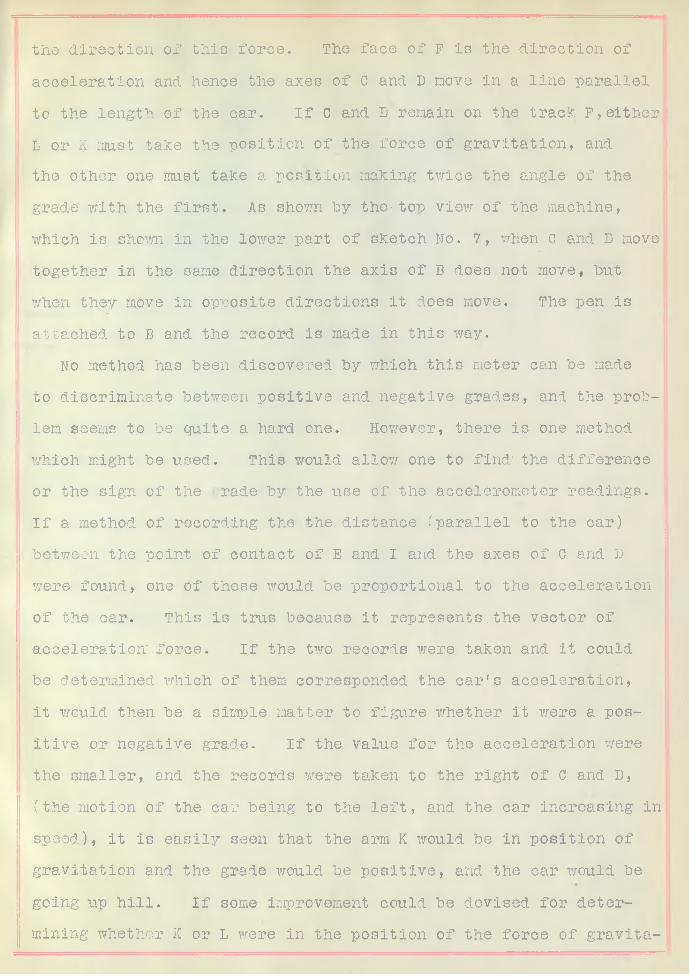
the direction of this force. The face of F is the direction of acceleration and hence the axes of G and D move in a line parallel to the length of the car. If C and D remain on the track F, either. L or K must take the position of the force of gravitation, and the other one must take a position making twice the angle of the grade with the first. As shown by the-ton view of the machine,which is shown in the lower part of sketch No. 7, when c and D move
'together in the same direction the axis of B does not move, but
i when they move in opposite directions it does move. The pen is attached to B and the record is made in this way.
No method has been discovered by which this meter can be made to discriminate between positive and negative grades, and the problem seems to be quite a hard one. However, there is one method which might be used. This would allow one to find' the difference or the sign of the rade by the use of the accelerometer readings.If a method of recording the the distance (parallel to the car)
i between the point of contact of E and I and the axes of C and D were found, one of these would be proportional to the acceleration of the car. This is trus because it represents.the vector of acceleration force. If the two records were taken and it could be determined which of them corresponded the car's acceleration, it would then be a simple matter to figure whether it were a positive or negative grade. If the value for the acceleration were ■the smaller, and the records were taken to the right of C and D,(the motion of the car being to the left, and the car increasing in speed), it is easily seen that the arm K would be in position of gravitation and the grade would be positive, and the car would be going up hill. If some improvement could be devised for determining whether K or L were in the position of the force of gravita-

tion, the meter could easily be made to record accelerations as well as grades, but no method for doing this has-been conceived.
Great care must be exercised on the machine work on this in-! ■ ■ ( ||strument, because unnecessary friction on bearings or rpufd?ness in
the track or a mistake in the size or the adjustment of the spring or the arms L and K would make the readings of no value.
The accompanying drawings are tracings for working drawings, and include two assembled views, and a complete set of detailed arid dimentioned tracings. The only parts which are not included in the drawings are 6, l/8 inch wood screws, 1-1/4 inches long,8, 1 j& inch screws, 1-1/2 Inches long, a coil spring which wouldstretch to about thirty inches under a stress of twenty pounds, a wire for supporting the weight, and a very light spring about twelve inches in length for keeping the string on the recording device stretched tight, and fastenings for the two springs. The numbers on the assembled views and the corresponding numbers on the detail sheets show where the different parts belong in the assembly. The assembled view: also shows the position of the meter, with respect to the apparatus table in the car.

SH£ TC£ /Vd 2 .

6 h -£ T C / J /VO 6

r n
S K E T C H /VO. 7

S A'/T TC ft A/& 9

D£T4/JL A/OZSc^/e 2"-/" J/ee/ 2
D S T A / L A/0 3
sS c& /e 2 " - / " S r e e /

DETAILS ca/e 2"- f " S
per /,].i - 4 l l l f
8
7J/<s
<
S ' 'f
\ Ai «*
A/a/re
D E T A / L A /0 . 3S c o / e 2 " = / " Stee/A/a/fe 2
l̂oo —4—
Jj L<s
DETAIL A/0./0S c £ > /& 2 " - / " Stee/Afa/ce/
------ 7
>
\------
> f O o
r
T T \* > V ?
i t
8<— ^ >
D 2 T A /L
S c a / e 2 " = / " S f e e ! /J

b £ h V-
c T
DETAIL VO /zSco/e 2= /' J/ee/ /
1 1 ’ ___1— -L -•_ _ ( 0 ;
J«>Si 1• iv i i J
c -L" )______
2 5
D£T/UL/V0./3* S c * / e / = £ " J f e e / Z
XV k 3
,____ _____ J[ ; .- ,\* .7✓ *y" ______r / "
Q £ T A //-A / 0 ./ 4
S c a / e / " - 2 " Sfee /\
I


Sca/e/ '= / ", Cost /ra/? j /Va/fe /

•kV*. i- 3" —>
l__ J
D C T /4/1 A / 0 . / 9
C ca / e C a s t
D £7~ 4/ / . M 0 . £ 0<Sca/e /"-2 " Cast //-osi

L i ' ' r /? 1*< - z >
111
- *111
r i\
* C i "1 &
__ !____ ,
r i 'i i
i
/"
r1
,_________ lJh
t-------- - f ' i ">
i
/rX _____
Q"#- 2—> /£
'--- H
r 1 1 1 i-i__iiii_i__ i
l'
ii1iIl
.___________L _
! L 1 1 1 1 1 1
Y il1i
n -----------------1 1
iiii
/ / "y “■ — <« $ " / /7
. 4- f
7 •• ? - <
‘ / & >
^ * 3 '
D £ r / ? / l /1/0.Z /
/>// J/z <? -
A fa


![Fo o d a n d Organisation N ac io n e s U n id as hj]ZgbaZpby [t ^bg … · 2017. 11. 21. · U n it e d N a t io n s O rg a n iz ac ió n d e las N ac io n e s U n id as p ara la](https://static.fdocuments.us/doc/165x107/5fc674c7318905619447cc34/fo-o-d-a-n-d-organisation-n-ac-io-n-e-s-u-n-id-as-hjzgbazpby-t-bg-2017-11-21.jpg)


![gZ N ac io n e s U n id as hj]ZgbaZpby GZpbc CONFERENCE · A g ric u lt u re O rg a n iz a t io n o f t h e U n it e d N a t io n s ... Twenty-eighth - Sana’a, Republic of Yemen,](https://static.fdocuments.us/doc/165x107/5c6ff23f09d3f29a798c502e/gz-n-ac-io-n-e-s-u-n-id-as-hjzgbazpby-gzpbc-a-g-ric-u-lt-u-re-o-rg-a-n-iz-a.jpg)