
TGHMS-3 HMS and HMG High Mounting Series Unit Heaters
16
STEAM, HOT WATER AND GAS HEATERS TO PROVIDE A COMFORTABLE ENVIRONMENT IN HIGH BAY AREAS HMS and HMG High Mounting Series Unit Heaters TecHnical GUide TGHMS-3
Transcript of TGHMS-3 HMS and HMG High Mounting Series Unit Heaters

STEAM, HOT WATER AND GAS HEATERS TO PROVIDE A COMFORTABLE ENVIRONMENT IN HIGH BAY AREAS
HMS and HMG High Mounting Series
Unit Heaters TecHnical GUide
TGHMS-3
2
4830 Transport Drive, Dallas, TX 75247 Tel. (214) 638-6010 www.ljwing.com In the interest of product improvement, L.J. Wing reserves the right to make changes without notice.
Since 1875, the L.J. Wing Company has been a leader in providing innovative solutions for difficult HVAC problems. Wing HMS and HMG Series heaters provide reliable air heating with steam, hot water or gas for tall open spaces such as aircraft hangars. This technical guide will help you size, select and specify the proper HMS or HMG model to satisfy your project’s heating requirements. If you have questions, please contact your local L.J. Wing representative; he will be glad to assist you.
3
TABLE OF CONTENTS
Operation . . . . . . . . . . . . . . . . . . . . . . . . . . . . . . . . . . . . . . . . . . . . . . . . . . . . . . . . . . . . . . . . . . . . . . . .4 Motor and Sound Data . . . . . . . . . . . . . . . . . . . . . . . . . . . . . . . . . . . . . . . . . . . . . . . . . . . . . . . . . . . . . .4 Model Number Description . . . . . . . . . . . . . . . . . . . . . . . . . . . . . . . . . . . . . . . . . . . . . . . . . . . . . . . . . .4 Selection and Performance . . . . . . . . . . . . . . . . . . . . . . . . . . . . . . . . . . . . . . . . . . . . . . . . . . . . . . . .6-7 Dimensions . . . . . . . . . . . . . . . . . . . . . . . . . . . . . . . . . . . . . . . . . . . . . . . . . . . . . . . . . . . . . . . . . . . .8-10 Piping . . . . . . . . . . . . . . . . . . . . . . . . . . . . . . . . . . . . . . . . . . . . . . . . . . . . . . . . . . . . . . . . . . . . . . . . . .11 Electrical . . . . . . . . . . . . . . . . . . . . . . . . . . . . . . . . . . . . . . . . . . . . . . . . . . . . . . . . . . . . . . . . . . . . .12-14 Specification and Schedule – HMG . . . . . . . . . . . . . . . . . . . . . . . . . . . . . . . . . . . . . . . . . . . . . . . . . . .15 Specification and Schedule – HMS . . . . . . . . . . . . . . . . . . . . . . . . . . . . . . . . . . . . . . . . . . . . . . . . . . .16

4
PRODUCT DESCRIPTION
Product OfferingL.J. Wing High Mounting Series unit heaters are specifically designed for heating aircraft hangars and other open spaces with very tall ceilings. Two different models are available: Type HMS - Designed for use with steam or hot water heat sources; Type HMG - Indirect natural gas-fired heating. Four models of both HMS and HMG units are offered as shown below.
Two styles of L.J. Wing’s unique revolving discharge are available with either HMS or HMG units to deliver the air down to the comfort level, five to six feet above the floor. A high-torque motor coupled with an idler gear drive rotates the discharge at approximately one rpm. This creates a gentle sweeping motion of air that results in better overall coverage with minimal temperature gradients from floor to ceiling.
ETL Coil Operating Parameters: Maximum elevation is 9,000 ft. (2,743.2m). Maximum operating temperature is 250°F (121.1°C). Minimum operating temperature is 0°F (-17.8°C). Maximum operating pressure is 100 PSIG (689 kPa). Minimum operating pressure is 2 PSIG (13.8 kPa).
Model Number Description
- -
Steam or Hot Water: HMS Discharge type:
HMS Size: 10,15, 20 or 30
HMG Size: 5, 7, 10 or 15
10R = type 10, revolving
Gas Heating: HMG 8R = type 8, revolving
HMG 15 10R
Airflow and Motor Data
24,000 10 3,150
26,700 15 3,300
29,300 15 3,500
30,800 20 3,650
23,700 2 @ 5 5,750
26,000 2 @ 5 5,950
28,000 2 @ 7 1/2 6,200
29,800 2 @ 7 1/2 6,45015
HMG57
10
10152030
HMS SIZE MOTOR HP
WEIGHT (LBS)
AIRFLOW (SCFM)

5
SELECTION
General Guidelines
The first step in selecting the proper heater is a calculation of the building heat loss. Next, select the quantity of HMS or HMG units to offset the calculated building heat loss. With the large heating capacities available with the HMS and HMG units, relatively few heaters are required even for large areas. This reduces the cost of installation, piping, wiring and controls with ongoing savings in operational and maintenance costs. Finally, select the type of discharge with the lowest maximum mounting height that yields the required coverage. Please consult your Wing representative for equipment selection at conditions outside the ranges described herein.
Unit Selection Procedure and Performance – HMS Steam
Select HMS units to meet the space heating requirements from the HMS – Steam Performance table at the given space temperature. Select the discharge capable of providing the necessary coverage, CV, at the required mounting height, MH. Calculate the Air Temperature Rise, ATR, across the HMG unit: ATR = (Q x 1,000)/(1.085 x CFM) where CFM is from Airflow, Motor and Sound table on page 4. Calculate the Leaving Air Temperature, LAT: LAT = EAT + ATR Calculate the condensate load, CL: CL = Q/LH where LH = 945 Btu/lbm
Example: Select HMS unit(s) to heat a space 420 feet long by 290 feet wide at a mounting height of 75 feet. Building heat loss is 9,300 MBtuh at a space temperature of 60º F. Solution: It will take six of any size HMS unit to meet the heating requirements with each HMS unit supplying at least Q = 9,300/6 = 1,550 Mbtuh. It can be seen that the smallest size HMS unit that can provide sufficient heat is size HMS-20: 6 x 1,574 = 9,444 Mbtuh. The required coverage is: 420/3 = 140 feet x 290/2 = 145 feet at a mounting height of 75 feet. Select a 10R discharge with MH = 78 feet with CV = 167 feet x 167 feet. ATR = (1,574 x 1,000)/(1.085 x 29,300) ATR = 49.5º F. LAT = 60 + 49.5 = 109.5º F. CL = (1,574 x 1,000)/ 945 = 1, 665.6 lbm/hr.
1. 2. 3. 4. 5.
1. 2. 3. 4. 5.
HMS - Steam Performance
Q MH CV MH CV Q MH CV MH CV(Mbtuh) (feet) (feet) (feet) (feet) (Mbtuh) (feet) (feet) (feet) (feet)1,391 54 125x125 62 144x144 1,307 57 132x132 66 152x152
1,486 61 136x136 71 156x156 1,397 64 143x143 75 164x164
1,574 68 147x147 78 167x167 1,480 72 154x154 83 176x176
1,624 72 153x153 82 174x174 1,527 76 161x161 87 183x183
Notes:
1. Performance shown is based on 5 psig steam pressure at the coil.
2. For higher steam pressures, the surface area will be reduced to produce the same performance.
3. Q = Heating Capacity; MH = Maximum Mounting Height; CV = Heating Coverage
30
SIZE101520
60o F space temperature 70o F space temperature8R Discharge 10R Discharge 8R Discharge 10R Discharge

6
SELECTION
Steam CoilsUnit Selection Procedure and Performance – HMS Hot Water
HMS - Hot Water Performance
Q MH CV MH CV Q MH CV MH CV(Mbtuh) (feet) (feet) (feet) (feet) (Mbtuh) (feet) (feet) (feet) (feet)1,364 55 127x127 63 146x146 1,255 59 137x137 68 158x158
1,449 62 139x139 72 159x159 1,338 67 148x148 78 171x171
1,534 69 150x150 80 171x171 1,410 74 160x160 86 184x184
1,581 74 156x156 84 178x178 1,453 78 167x167 90 191x191
GPM WPD GPM WPD(gpm) (feet H2O) (gpm) (feet H2O)145.5 7.3 133.9 6.2
149.0 7.6 141.9 7.0
158.0 8.5 145.0 7.3
163.0 8.2 150.0 7.7
Notes:
1.
2. Q = Heating Capacity; MH = Maximum Mounting Height; CV = Heating Coverage.
1520
30
Performance shown is based on 200 o F entering water temperature and a 20 o F water temperature drop through the
coil. Consult factory for performance at other conditions.
30
60o F space temp. 70o F space temp.
SIZE10
SIZE101520
60o F space temperature 70o F space temperature8R Discharge 10R Discharge 8R Discharge 10R Discharge
Select HMS units to meet the space heating requirements from the HMS – Hot Water Performance table at the given space temperature. Select the discharge capable of providing the necessary coverage, CV, at the required mounting height, MH. Calculate the Air Temperature Rise, ATR, across the HMS unit: ATR = (Q x 1,000)/(1.085 x CFM) Calculate the Leaving Air Temperature, LAT: LAT = EAT + ATR Look up the required water flow rate, GPM, and Water Pressure drop, WPD, from the HMS – Hot Water Performance table
Example: Select HMS unit(s) to heat a space 282 feet long by 282 feet wide at a mounting height of 65 feet using 200º F hot water with a 20º F water temperature drop. Building heat loss is 5,150 MBtuh at a space temperature of 70º F. Solution: It will take four of any size HMS unit to meet the heating requirements with each HMS unit supplying at least Q = 5,160/4 = 1,290 Mbtuh. It can be seen that the smallest size HMS unit that can provide sufficient heat is size HMS-15: 4 x 1,338 = 5,352 Mbtuh. The required coverage is: 282/2 = 141 feet by 282/2 = 141 feet. Select an 8R discharge with MH = 67 feet and CV = 148 feet x 148 feet. ATR = (1,338 x 1,000)/(1.085 x 26,700) ATR = 46.2º F. LAT = 60 + 46.2 = 106.7º F. GPM = 141.9; WPD = 7.0 feet H2O
1. 2. 3. 4. 5.
1. 2. 3. 4. 5.

7
SELECTION
Steam CoilsUnit Selection Procedure and Performance – HMG
HMG Performance
Q MH CV MH CV Q MH CV MH CV(Mbtuh) (feet) (feet) (feet) (feet) (Mbtuh) (feet) (feet) (feet) (feet)1,280 58 135x135 67 155x155 1,280 58 135x135 67 155x155
1,280 69 154x154 81 177x177 1,280 69 153x153 81 177x177
1,280 80 172x172 93 199x199 1,280 80 172x172 93 198x198
1,280 86 183x183 100 211x211 1,280 86 182x182 100 210x210
Note:
1. Q = Heating Capacity; MH = Maximum Mounting Height; CV = Heating Coverage.
15
SIZE57
10
60o F space temperature 70o F space temperature8R Discharge 10R Discharge 8R Discharge 10R Discharge
Select HMG units to meet the space heating requirements from HMG – Performance table at the given space temperature. Select the discharge capable of providing the necessary coverage, CV, at the required mounting height, MH. Calculate the Air Temperature Rise, ATR, across the HMG unit: ATR = (Q x 1,000)/(1.085 x CFM) Calculate the Leaving Air Temperature, LAT: LAT = EAT + ATR
Example: Select HMG unit(s) to heat a space 200 feet long by 200 feet wide at a mounting height of 96 feet. Building heat loss is 1,265 MBtuh at a space temperature of 60º F. Solution: It will take only one of any size HMG unit to meet the heating requirements: Q = 1,280 Mbtuh. The required coverage is 200 feet by 200 feet. Select a HMG-15 unit with a 10R discharge to yield MH = 100 feet and CV = 211 feet x 211 feet. ATR = (1,280 x 1,000)/(1.085 x 29,800) ATR = 39.6º F. LAT = 60 + 39.6 = 99.6º F.
1. 2. 3. 4.
1. 2. 3. 4.

8
DIMENSIONS
HMS Unit Dimensions C000589
26
R/A
FRONT ELEVATION
R/A
SIDE ELEVATION
24
26
5
8
INLET CONNECTION FOR STEAM AND 4. ADJUSTABLE MOTOR BASE
6. EQUIPMENT SUPPORT (BY OTHERS)
13. INLET OPENING WITH BIRDSCREEN
11. ACCESS DOOR
7
OUTLET CONNECTION FOR HOT WATER
3
2. COIL CONNECTION - 2" NPT TYPICAL
3. ELECTRICAL ENCLOSURE
5. OSHA BELT GUARD
12. V-BANK FILTER SECTION
12
9. SUPPORT CHANNEL 10. OPTIONAL ISOLATORS (SHIPPED LOOSE)
610
13
11
R/A
FRONT ELEVATION
R/A
SIDE ELEVATION
24
6"
16
S/A
5
8
1
2
4
7 3
610
11
APPROX.
COMPONENT IDENTIFICATION
9
AND OPTIONAL FILTER SECTION
HMS UNIT WITH STEAM OR HOT WATER COILS
SEE PAGE 10FOR DIMENSION
FOR DISCHARGE OPTIONSSEE PAGE 10
HMS UNIT WITH STEAM OR HOT WATER COILS
13
6414 321
2 3212463
4
5158
11134
S/A
6414
3212 321
24634
1
2
9
4
FOR DISCHARGE OPTIONSSEE PAGE 10
16334
6"
16
APPROX.SEE PAGE 10
FOR DIMENSION
5158
S/A S/A
711
13
711 12
13
8. LIFTING LUGS 1. COIL CONNECTION - 2" NPT TYPICAL
7. HEATING COIL OUTLET CONNECTION FOR STEAM AND INLET CONNECTION FOR HOT WATER

9
DIMENSIONS
PLAN VIEW
FRONT ELEVATIONSIDE ELEVATION
S/A
R/AR/A
6026 26
62
140
15TYPICAL
51
18
112
42
50
48
TYPICAL
1. FURNACE FLUE 5" DIAMETER
6. DUCT FURNACE INLET8. DIMENSIONS FOR SUPPORTING UNIT2. GAS INLET CONNECTION (OPTIONAL)
3. DISCONNECT SWITCH (OPTIONAL)
4. EXTENDED BEARING LUBE LINES5. MOTOR WITH ADJUSTABLE BASE
7. ACCESS DOORS (BOTH ENDS)
9. LIFTING LUGS
COMPONENT IDENTIFICATION
2
1
34 5
67
8
8
9
HMG UNIT WITH GAS FURNACES
2934
9818
201516
201516
11912
SEE PAGE 10FOR DIMENSION
FOR DISCHARGEOPTIONS
SEE PAGE 10
Steam CoilsHMG Unit Dimensions C00026C000590

10
DIMENSIONS
Discharges C00026C000591
END ELEVATION SIDE ELEVATION
END ELEVATION SIDE ELEVATION
HMS AND HMG DISCHARGES
STYLE 8R DISCHARGE
STYLE 10R DISCHARGE

11
PIPING
Steam and Hot Water Piping Diagram C00026
HMS UNIT HEATER STEAM AND HOT WATER PIPING DIAGRAM
T
61
4 9 18
5 1
3 110
7
12112
111 12"
6"
STEAM PIPING LEGEND
1. GLOBE OR GATE VALVE
(FOR GRAVITY ATMOSPHERIC RETURN SYSTEMS)
2. OPTIONAL MOTORIZED SHUT-OFF VALVE3. BY-PASS TO ALLOW SERVICING OF MOTORIZED VALVE.
BYPASS LINE TO BE THE SAME SIZE AS MOTORIZED VALVE.4. INVERTED BUCKET OR COMBINATION FLOAT AND
THERMOSTATIC TRAP WITH VENT.5. BY-PASS TO PERMIT SERVICING OF TRAP. BY-PASS TO
BE ONE PIPE SIZE LARGER THAN TRAP ORIFICE.
7. STEAM SUPPLY MAIN.8. CONDENSATE RETURN MAIN.9. 15° SWING CHECK VALVE.
10. 1/2" SPRING LOADED VACUUM BREAKERVENTED TO ATMOSPHERE.
11. STEAM STRAINER WITH BLOW-DOWN VALVE.12. 1/2" DRAIN VALVE. TO BE OPENED WHEN GLOBE
OR GATE SHUTOFF VALVE IS CLOSED.6. DIRT POCKET AND DRIP LEG. TO BE THE SAME SIZE
AS THE HEATER CONDENSATE RETURN LINE.
HOT WATER PIPING LEGEND
1. GLOBE OR GATE VALVE2. AUTOMATIC AIR VENT
4. WATER FLOW CONTROL VALVE5. HOT WATER SUPPLY LINE
3. COIL DRAIN VALVE 6. HOT WATER RETURN LINE
3
4
5
216
NOTE : ABOVE DIAGRAMS ARE FOR ONLY ONE OF TWO COILS PROVIDED ON UNIT. DUPLICATE PIPING FOR REMAINING COIL.
AIR FLOW
AIR FLOW
C000697

12
ELECTRICAL
Wiring Diagram – HMS – Typical 3-Phase C000698
ST-01OL
DENOTES FIELD WIRING BY OTHERSAND WIRED BY OTHERSDENOTES COMPONENTS SUPPLIEDTERMINAL BLOCK AND WIRE NUMBERDENOTES CONTROL CABINET
DENOTES WIRE CONNECTION
DENOTES JUMPER WIRENUMBER AND WIRINGDENOTES COMPONENT TERMINAL
COMPONENTS OR SECTIONS MAY BE REQUIREDFIELD CONNECTIONS AND/OR WIRING BETWEENNOTE: BECAUSE OF SHIPPING RESTRICTIONS
NOTES
TO THE LATEST PROVISIONS OF NECUNIT SHALL BE GROUNDED ACCORDING
OPTIONAL COMPONENT IDENTIFICATION
3
OLFU-11
ST-01 MAIN SUPPLY FAN MOTOR STARTER
MAIN DISCONNECT FUSEMOTOR OVERLOAD
ST-015
MT-01 MAIN SUPPLY FAN MOTOR
4
FU-09
SW-01SW-14
TC-01
CONTROL CIRCUIT FUSE
MAIN DISCONNECT SWITCHSUMMER-OFF-WINTER SWITCH (REMOTE)
ROOM THERMOSTAT
S-O-W
SW-14
6
MT-37
TC-01
SV-01
MT-37 REVOLVING DISCHARGE MOTOR
TR-01 CONTROL TRANSFORMER
SV-01 STEAM SOLENOID VALVE
OL
FU-09
115 VAC1
3 PHASE
VOLT
TR-01
60 HERTZ
3 WIRE
FU-11
SW-01
OPEN MAIN DISCONNECTCAUTION:SWITCH BEFORE SERVICING EQUIPMENT.MT-01
ST-01
T2
T3
2
T1
MODEL HMS-10, HMS-15, HMS-20 AND HMS-30TYPICAL WIRING DIAGRAM FOR
13
ELECTRICAL
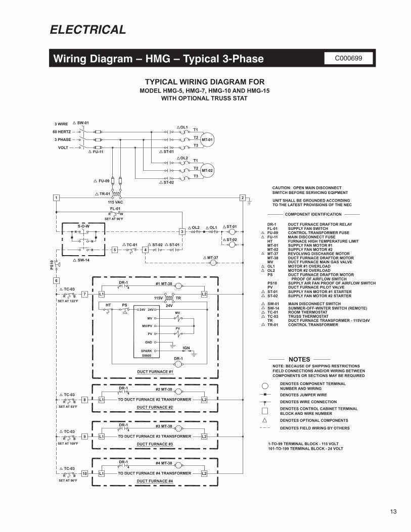
Wiring Diagram – HMG – Typical 3-Phase C000699
6
101-TO-199 TERMINAL BLOCK - 24 VOLT1-TO-99 TERMINAL BLOCK - 115 VOLT
NOTESNOTE: BECAUSE OF SHIPPING RESTRICTIONSFIELD CONNECTIONS AND/OR WIRING BETWEENCOMPONENTS OR SECTIONS MAY BE REQUIRED
DENOTES COMPONENT TERMINALNUMBER AND WIRINGDENOTES JUMPER WIRE
DENOTES WIRE CONNECTION
DENOTES CONTROL CABINET TERMINALBLOCK AND WIRE NUMBER
DENOTES OPTIONAL COMPONENTS
DENOTES FIELD WIRING BY OTHERS
FU-09
MV
HT
OL1
PVST-01
SW-01SW-14
TC-03TRTR-01
CONTROL TRANSFORMER FUSE
DUCT FURNACE MAIN GAS VALVE
FURNACE HIGH TEMPERATURE LIMIT
MOTOR #1 OVERLOAD
DUCT FURNACE PILOT VALVE SUPPLY FAN MOTOR #1 STARTER
MAIN DISCONNECT SWITCHSUMMER-OFF-WINTER SWITCH (REMOTE)
TRUSS THERMOSTATDUCT FURNACE TRANSFORMER - 115V/24VCONTROL TRANSFORMER
COMPONENT IDENTIFICATION
MT-37 REVOLVING DISCHARGE MOTOR
24V
115V
IGN
MV
24V24V
PV
GND
MV/PV
S8600
TR
FU-11 MAIN DISCONNECT FUSE
PS
MV
PV
DUCT FURNACE DRAFTOR MOTORMT-38
#1 MT-38
SPARK
HT
TC-03L1
DUCT FURNACE #2
DR-1
DUCT FURNACE DRAFTOR MOTOR PS
TC-01 ROOM THERMOSTAT
TO DUCT FURNACE #2 TRANSFORMER
SUPPLY FAN MOTOR #1MT-01
OL1
FU-09
SW-14
S-O-W
115 VAC1
3 PHASE
VOLT
TR-01
60 HERTZ
3 WIRE
FU-11
SW-01
OPEN MAIN DISCONNECT CAUTION:
UNIT SHALL BE GROUNDED ACCORDINGTO THE LATEST PROVISIONS OF THE NEC
SWITCH BEFORE SERVICING EQIPMENT
5TC-01
4ST-02
MT-01
ST-01
T2
T3
MT-37
OL23
ST-01
2
T1
MODEL HMG-5, HMG-7, HMG-10 AND HMG-15
SET AT 122°F
DUCT FURNACE #1
FL-01
SET AT 96°F
FL-01 SUPPLY FAN SWITCHDR-1 DUCT FURNACE DRAFTOR RELAY
1 4
R W
R B
R B
R B
R B
X
X
X
TC-03
TC-03
TC-03
SET AT 83°F
SET AT 109°F
SET AT 96°F
DR-1
7 L2
#2 MT-38
L1
DR-11 4
8 L2
DUCT FURNACE #3
TO DUCT FURNACE #3 TRANSFORMER
#3 MT-38
L1
DR-11 4
9 L2
DUCT FURNACE #4
TO DUCT FURNACE #4 TRANSFORMER
#4 MT-38
L1
DR-11 4
10 L2
OL2
MT-02
ST-02
T2
T3
T1
OL2 MOTOR #2 OVERLOAD
SUPPLY FAN MOTOR #2MT-02
PROOF OF AIRFLOW SWITCHSUPPLY AIR FAN PROOF OF AIRFLOW SWITCHPS10
ST-02 SUPPLY FAN MOTOR #2 STARTER
OL1
ST-01 ST-02
PS10
WITH OPTIONAL TRUSS STAT
TYPICAL WIRING DIAGRAM FOR

14
ELECTRICAL
Amp Draw Table
Truss thermostats can be used to control the discharge air temperature of HMG Series unit heaters by turning “on” or “off” individual furnaces based on inlet air temperature. To accomplish this, a truss thermostat is mounted and wired on the inlet duct. It has a bulb-type sensor that is fixed to the outside of the unit. In this manner, high temperature air that is stratified in the truss can be redistributed to the working levels when the need for it exists – without operating the burners. Process heat that would normally be wasted can be economically put to use. Also, discharge temperatures can be effectively managed to assure optimum projection. Elevated truss temperatures will increase discharge temperatures. Extremely high temperature air is light in weight and therefore difficult to project from high mounting heights.
Truss Thermostats (HMG only)
AMPS for 208V 3 Ph
AMPS for 230V 3 Ph
AMPS for 460V 3 Ph
AMPS for 575V 3 Ph
AMPS for 208V 3 Ph
AMPS for 230V 3 Ph
AMPS for 460V 3 Ph
AMPS for 575V 3 Ph
NOTES:
1. Above motor amps are based on the latest edition of the National Electrical Code.
2. Control circuit amps are based on standard controls.
Procedure for sizing optional disconnect switch:1. Find the required blower motor HP from Airflow, Motor and Sound Data table on page 4.
2. Find amp draw for required blower motor HP and electrical service from above chart in Item A.3. Find amps for control circuit from above chart in Item B.
4. Add amps from step 2 and step 3, then multiply by 1.25.
ITEM24.2
5
22.0
7 1/2AMPSSOURCE
A
6.1
7.6
22.0
11.0
9.0
27.014.0 21.0
42.0
46.2
AMPS
2.2
2.4
11.0 17.0
CONTROL CIRCUIT AMPS
1559.4
54.0
30.8
28.0BlowerMotor
MOTOR HORSEPOWER2010
B
0.9
16.7
15.2
1.1
ControlTransformer
Here is a typical four truss thermostat set up: With the room thermostat calling for heat, a typical four burner unit operates as follows: Ent. Air Temp. Disc. Air Temp. Burners on 70 º F 122 º F 4 (all) 83 º F 122 º F 3 96 º F 122 º F 2 109 º F 122 º F 1 122 º F 122 º F 0 (none) Note: Temperature rise through the unit is 52 º F.
BURNER#1 BURNER #3
BURNER#2 BURNER #4
TRUSS STAT SETTING 83° F.
INLET AIR
TEMP. 70° F.
DISCHARGE AIR TEMP. 122° F.
TRUSS STAT SETTING 109° F.
TRUSS STAT SETTING 122° F.
TRUSS STAT SETTING 96° F.
INLET AIR
TEMP. 70° F.

15
SPECIFICATIONS AND SCHEDULE – HMG
Typical Specification – HMG
Typical Schedule – HMG
General Furnish a factory-assembled HMG model High Mounting Series heater as manufactured by L.J. Wing, Dallas, TX, to heat air in a high ceiling application. Heating medium shall be gas. Performance shall be as shown in the schedule. Heater Section Unit shall include four (4) (natural gas)(propane) indirect –fired furnaces. Each furnace shall be complete with power vent system, sealed flue collector, electronic flame supervision, and energy-saving electric ignition system. Each furnace shall display the AGA/CGA seal of design compliance and be factory tested to assure field operation. The casing of each furnace shall be made of die-formed, heavy-gauge steel, phosphatized to inhibit rust and corrosion. Each furnace shall have a die-formed (aluminized steel ) (Series 409 stainless steel) heat exchanger, and its own gas control piping train, arranged to facilitate field piping to a common supply manifold. The safety controls shall include a combustion air pressure switch to verify proper powered vent flow before allowing the gas valve to open. Finish Unit casing and discharge shall be fabricated of heavy-gauge, galvannealed sheet steel. Both casing and discharge shall be painted inside and out with an air-dried alkyd enamel finish.
Blower Assembly The blower section shall include two centrifugal, heavy-duty, double-width, double-inlet blowers. Each blower shall be complete with motor and drive. Blower ratings shall be based on tests made in accordance with AMCA Standard 211, and shall bear the AMCA seal. All air ratings are based on delivery against the external static pressure shown in the schedule with all optional equipment in place and operating. Blower wheels shall have tapered spun wheel cones or shrouds to provide stable airflow and high rigidity. The fan wheels shall be non-overloading with backward inclined blades of single thickness, welded to the rim and back plate. Riveted construction is unacceptable. Blowers shall be dynamically balanced at operating speed on precision, electronic vibration-amplifying equipment to ensure quiet, smooth-running, trouble-free operation. Discharge Unit shall be furnished with a revolving discharge as listed on the schedule to assure proper air projection and distribution. The revolving discharge shall consist of a slowly rotating air distributor, properly balanced and suspended from the heater casing on two prelubricated, sealed, ball bearings. A small, high-torque motor shall rotate the discharge by means of an idler gear drive that ensures positive traction and final rotation at approximately one RPM. All discharge outlets shall be fitted with adjustable deflectors to facilitate field adjustment of the discharge air pattern. Options (A) Furnish magnetic motor starter with overload block that is factory-wired and mounted in a NEMA 1 electrical control box. (B) Furnish fused disconnect switch that is factory-wired and mounted in a NEMA 1 electrical control box.
Ent. Air Leav. AirModel Temp. Temp.
No. (o F) (o F)HMG-15-8R 29,800 60 100 1,280 2 @ 7.5 460/3/60
Heat Transfer (MBtuh)
Motor Horsepower
(HP)Electrical Service (volts/phase/Hz)
Airflow (SCFM)

16
4830 Transport Drive, Dallas, TX 75247 Tel. (214) 638-6010
www.ljwing.comPrinted in USA Copyright USA, 2019
SPECIFICATIONS AND SCHEDULE – HMS
Typical Specification – HMS
General Furnish a factory-assembled HMS model High Mounting Series heater as manufactured by L.J. Wing, Dallas, TX, to heat air in a high ceiling application. Heating medium shall be steam or hot water. Performance shall be as shown in the schedule. Coils Coils shall be fabricated of seamless return bend type 5/8” O.D. copper tubes with corrugated plate aluminum fins of not less than 0.006 inches thickness. Coils shall be tested and rated in accordance with ARI Standard 410. The coil casing shall be constructed of galvanized sheet metal, minimum 16 gauge. Finish Unit casing and discharge shall be fabricated of heavy-gauge, galvannealed sheet steel. Both casing and discharge shall be painted inside and out with an air-dried alkyd enamel finish. Blower Assembly The blower section shall include two centrifugal, heavy-duty, double-width, double-inlet blowers. Each blower shall be complete with motor and drive. Blower ratings shall be based on tests made in accordance with AMCA Standard 211, and shall bear the AMCA seal. All air ratings are based on delivery against the external static pressure shown in the schedule with all optional equipment in place and operating.
Blower wheels shall have tapered spun wheel cones or shrouds to provide stable airflow and high rigidity. The fan wheels shall be non-overloading with backward inclined blades of single thickness, welded to the rim and back plate. Riveted construction is unacceptable. Blowers shall be dynamically balanced at operating speed on precision, electronic vibration-amplifying equipment to ensure quiet, smooth-running, trouble-free operation. Discharge Unit shall be furnished with a revolving discharge as listed on the schedule to assure proper air projection and distribution. The revolving discharge shall consist of a slowly rotating air distributor, properly balanced and suspended from the heater casing on two prelubricated, sealed, ball bearings. A small, high-torque motor shall rotate the discharge by means of an idler gear drive that ensures positive traction and final rotation at approximately one RPM. All discharge outlets shall be fitted with adjustable deflectors to facilitate field adjustment of the discharge air pattern. Options (A) Furnish magnetic motor starter with overload block that is factory-wired and mounted in a NEMA 1 electrical control box. (B) Furnish fused disconnect switch that is factory-wired and mounted in a NEMA 1 electrical control box.
Typical Schedule
Ent. Air Leav. Air Steam Heat Condensate Motor Electrical Model Airflow Temp. Temp. Pressure Transfer load Horsepower Service
No. (SCFM) (o F) (o F) (psig) (MBtuh) (lbm/hr) (HP) (volt/ph./Hz)HMS-20-10R 29,300 60 110 5 1,574 1,666 15 230/3/60