TFC RA50 (VUS91EN-01(USA 120) - Vents Usvents-us.com/images/cat/704_369_cat_file.pdf · 3 • Read...
22
USER’S MANUAL TwinFresh Comfo: • RA-50 • RA1-50 • RA-50-2 • RA1-50-2 Single-room reversible energy regeneration ventilator
Transcript of TFC RA50 (VUS91EN-01(USA 120) - Vents Usvents-us.com/images/cat/704_369_cat_file.pdf · 3 • Read...

USER’S MANUAL
TwinFresh Comfo:
• RA-50• RA1-50• RA-50-2• RA1-50-2
Single-room reversible energy regeneration ventilator
www.ventilation-system.com2
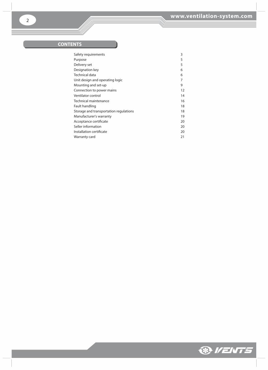
Safety requirements 3Purpose 5Delivery set 5Designation key 6Technical data 6Unit design and operating logic 7Mounting and set-up 9Connection to power mains 12Ventilator control 14Technical maintenance 16Fault handling 18Storage and transportation regulations 18Manufacturer's warranty 19Acceptance certifi cate 20Seller information 20Installation certifi cate 20Warranty card 21
CONTENTS
3
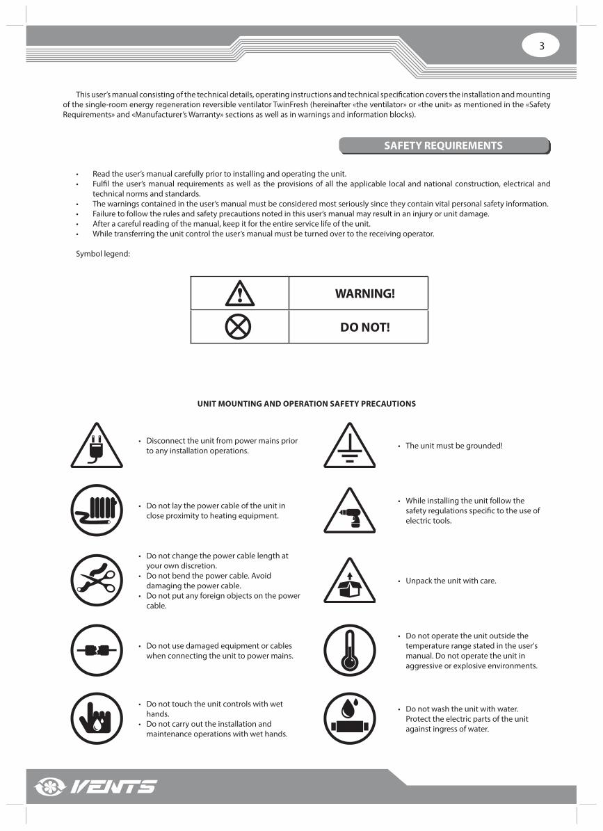
• Read the user’s manual carefully prior to installing and operating the unit.• Fulfi l the user’s manual requirements as well as the provisions of all the applicable local and national construction, electrical and
technical norms and standards.• The warnings contained in the user’s manual must be considered most seriously since they contain vital personal safety information.• Failure to follow the rules and safety precautions noted in this user’s manual may result in an injury or unit damage.• After a careful reading of the manual, keep it for the entire service life of the unit.• While transferring the unit control the user’s manual must be turned over to the receiving operator.
Symbol legend:
WARNING!
DO NOT!
SAFETY REQUIREMENTS
This user’s manual consisting of the technical details, operating instructions and technical specifi cation covers the installation and mounting of the single-room energy regeneration reversible ventilator TwinFresh (hereinafter «the ventilator» or «the unit» as mentioned in the «Safety Requirements» and «Manufacturer’s Warranty» sections as well as in warnings and information blocks).
UNIT MOUNTING AND OPERATION SAFETY PRECAUTIONS
• Disconnect the unit from power mains prior to any installation operations. • The unit must be grounded!
• Do not lay the power cable of the unit in close proximity to heating equipment.
• While installing the unit follow the safety regulations specifi c to the use of electric tools.
• Do not change the power cable length at your own discretion.
• Do not bend the power cable. Avoid damaging the power cable.
• Do not put any foreign objects on the power cable.
• Unpack the unit with care.
• Do not use damaged equipment or cables when connecting the unit to power mains.
• Do not operate the unit outside the temperature range stated in the user's manual. Do not operate the unit in aggressive or explosive environments.
• Do not touch the unit controls with wet hands.
• Do not carry out the installation and maintenance operations with wet hands.
• Do not wash the unit with water. Protect the electric parts of the unit against ingress of water.

www.ventilation-system.com4
UNIT MOUNTING AND OPERATION SAFETY PRECAUTIONS
• Do not allow children to operate the unit. • Disconnect the unit from power mains prior to any technical maintenance.
• Do not store any explosive or highly fl ammable substances in close proximity to the unit.
• When the unit generates unusual sounds, odour or emits smoke disconnect it from power supply and contact the Seller.
• Do not open the unit during operation.• Do not direct the air fl ow produced by
the unit towards open fl ame or ignition sources.
• Do not block the air duct when the unit is switched on.
• In case of continuous operation of the unit periodically check the security of mounting.
• Do not sit on the unit and avoid placing foreign objects on it.
• Use the unit only for its intended purpose.

5
PURPOSE
DELIVERY SET
The ventilator is designed to ensure continuous mechanical air exchange in fl ats, cottages, hotels, cafes and other domestic and public premises. The ventilator is equipped with a ceramic regenerator that enables supply of fresh fi ltered air heated by means of extract air heat energy regeneration.
The ventilator is designed for through-the-wall mounting. The telescopic ventilator design enables its installation in the walls with various thickness, see the table below:
Wall thickness Ventilator model
240 mm - 425 mm (9 7/16’’ - 16 3/4”) • RA-50 • RA1-50
120 mm - 300 mm (4 3/4’’ - 11 13/16’’) • RA-50-2• RA1-50-2
The unit is rated for continuous operation.Transported air must not contain any fl ammable or explosive mixtures, evaporation of chemicals, sticky substances, fi brous materials,
coarse dust, soot and oil particles or environments favourable for the formation of hazardous substances (toxic substances, dust, pathogenic germs).
Name Number
Ventilator 1 item
Fastening set 1 item
Remote control 1 item
User's manual 1 item
Packing box 1 item
THE UNIT MAY NOT BE OPERATED BY CHILDREN OR PERSONS WITH REDUCED PHYSICAL, MENTAL OR SENSORY CAPACITIES, OR LACKING THE APPROPRIATE TRAINING. THE UNIT MUST BE INSTALLED AND CONNECTED ONLY BY PROPERLY QUALIFIED PERSONNEL AFTER THE APPROPRIATE BRIEFING. THE CHOICE OF UNIT INSTALLATION LOCATION MUST PREVENT UNAUTHORIZED ACCESS BY UNATTENDED CHILDREN.
www.ventilation-system.com6
DESIGNATION KEY
TECHNICAL DATA
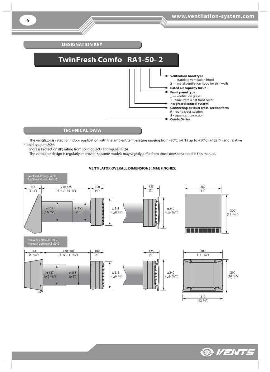
TwinFresh Comfo RА1-50- 2
Ventilation hood type_ — standard ventilation hood2 — metal ventilation hood for thin walls
Comfo Series
Connecting air duct cross-section formR - round cross-section S - square cross-section
Integrated control system
Front panel type_ — ventilation grille1 - panel with a flat front cover
Rated air capacity [m3/h]
The ventilator is rated for indoor application with the ambient temperature ranging from -20°C (-4 °F) up to +50°C (+122 °F) and relative humidity up to 80%.
Ingress Protection (IP) rating from solid objects and liquids IP 24.The ventilator design is regularly improved, so some models may slightly diff er from those ones described in this manual.
TwinFresh Comfo RA-50-2 TwinFresh Comfo RA1-50-2
TwinFresh Comfo RA-50TwinFresh Comfo RA1-50
213( 8 3⁄8")
213( 8 3⁄8")
240( 9 7⁄16"")
240( 9 7⁄16"")
120-300(4 ¾"-11 13⁄16")
100(4")
125 (5")
100(4")
125 (5")
144(5 11⁄16")
ø 157(ø 6 3⁄16")
ø 153(ø 6")
ø 157(ø 6 3⁄16")
ø 153(ø 6")
300(11 13⁄16")
310 (12 3⁄16")
260(10 ¼")
300 (11 13⁄16")
28011"
240-425(9 7⁄16’’ - 16 ¾”)
133(5 ¼")
VENTILATOR OVERALL DIMENSIONS [MM] (INCHES)
7
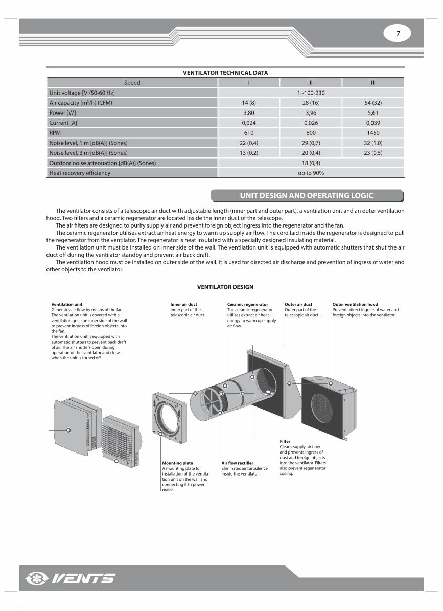
VENTILATOR TECHNICAL DATA
Speed I II III
Unit voltage [V /50-60 Hz] 1~100-230
Air capacity [m3/h] (CFM) 14 (8) 28 (16) 54 (32)
Power [W] 3,80 3,96 5,61
Current [A] 0,024 0,026 0,039
RPM 610 800 1450
Noise level, 1 m [dB(A)] (Sones) 22 (0,4) 29 (0,7) 32 (1,0)
Noise level, 3 m [dB(A)] (Sones) 13 (0,2) 20 (0,4) 23 (0,5)
Outdoor noise attenuation [dB(A)] (Sones) 18 (0,4)
Heat recovery effi ciency up to 90%
UNIT DESIGN AND OPERATING LOGIC
The ventilator consists of a telescopic air duct with adjustable length (inner part and outer part), a ventilation unit and an outer ventilation hood. Two fi lters and a ceramic regenerator are located inside the inner duct of the telescope.
The air fi lters are designed to purify supply air and prevent foreign object ingress into the regenerator and the fan.The ceramic regenerator utilises extract air heat energy to warm up supply air fl ow. The cord laid inside the regenerator is designed to pull
the regenerator from the ventilator. The regenerator is heat insulated with a specially designed insulating material. The ventilation unit must be installed on inner side of the wall. The ventilation unit is equipped with automatic shutters that shut the air
duct off during the ventilator standby and prevent air back draft.The ventilation hood must be installed on outer side of the wall. It is used for directed air discharge and prevention of ingress of water and
other objects to the ventilator.
VENTILATOR DESIGN
Ventilation unitGenerates air flow by means of the fan. The ventilation unit is covered with a ventilation grille on inner side of the wall to prevent ingress of foreign objects into the fan.The ventilation unit is equipped with automatic shutters to prevent back draft of air. The air shutters open during operation of the ventilator and close when the unit is turned off.
Mounting plateA mounting plate for installation of the ventila-tion unit on the wall and connecting it to power mains.
Air flow rectifierEliminates air turbulence inside the ventilator.
Outer air ductOuter part of the telescopic air duct.
Inner air ductInner part of the telescopic air duct.
Outer ventilation hoodPrevents direct ingress of water and foreign objects into the ventilator.
FilterCleans supply air flow and prevents ingress of dust and foreign objects into the ventilator. Filters also prevent regenerator soiling.
Ceramic regeneratorThe ceramic regenerator utilises extract air heat energy to warm up supply air flow.
www.ventilation-system.com8
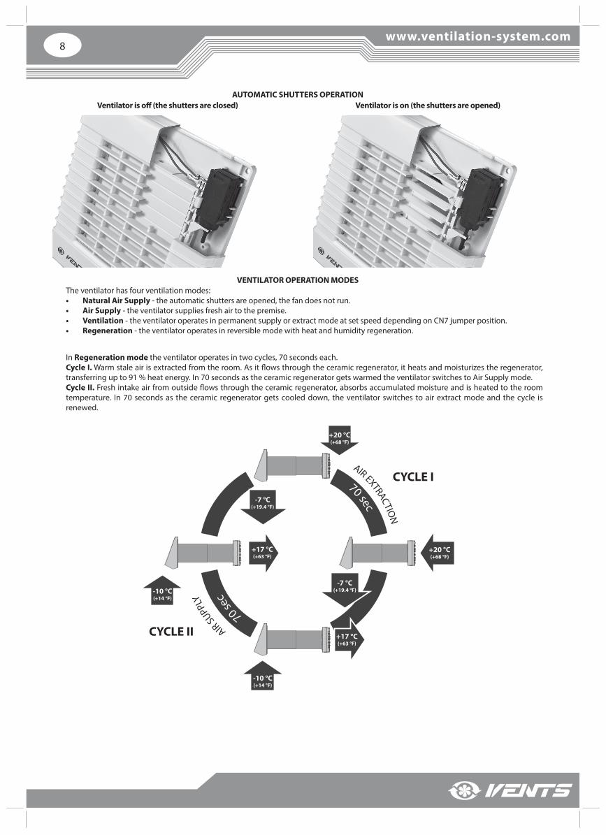
AUTOMATIC SHUTTERS OPERATION
VENTILATOR OPERATION MODESThe ventilator has four ventilation modes:• Natural Air Supply - the automatic shutters are opened, the fan does not run.• Air Supply - the ventilator supplies fresh air to the premise.• Ventilation - the ventilator operates in permanent supply or extract mode at set speed depending on CN7 jumper position.• Regeneration - the ventilator operates in reversible mode with heat and humidity regeneration.
Ventilator is off (the shutters are closed) Ventilator is on (the shutters are opened)
AIR EXTRACTION
A
IR SUPP
LY
CYCLE I
CYCLE II
70 sec
70 se
c-10 °С(+14 °F)
-10 °С(+14 °F)
+20 °С(+68 °F)
+20 °С(+68 °F)
+17 °С(+63 °F)
-7 °С(+19.4 °F)
-7 °С(+19.4 °F)
+17 °С(+63 °F)
In Regeneration mode the ventilator operates in two cycles, 70 seconds each. Cycle I. Warm stale air is extracted from the room. As it fl ows through the ceramic regenerator, it heats and moisturizes the regenerator, transferring up to 91 % heat energy. In 70 seconds as the ceramic regenerator gets warmed the ventilator switches to Air Supply mode.Cycle II. Fresh intake air from outside fl ows through the ceramic regenerator, absorbs accumulated moisture and is heated to the room temperature. In 70 seconds as the ceramic regenerator gets cooled down, the ventilator switches to air extract mode and the cycle is renewed.
9
MOUNTING AND SET-UP
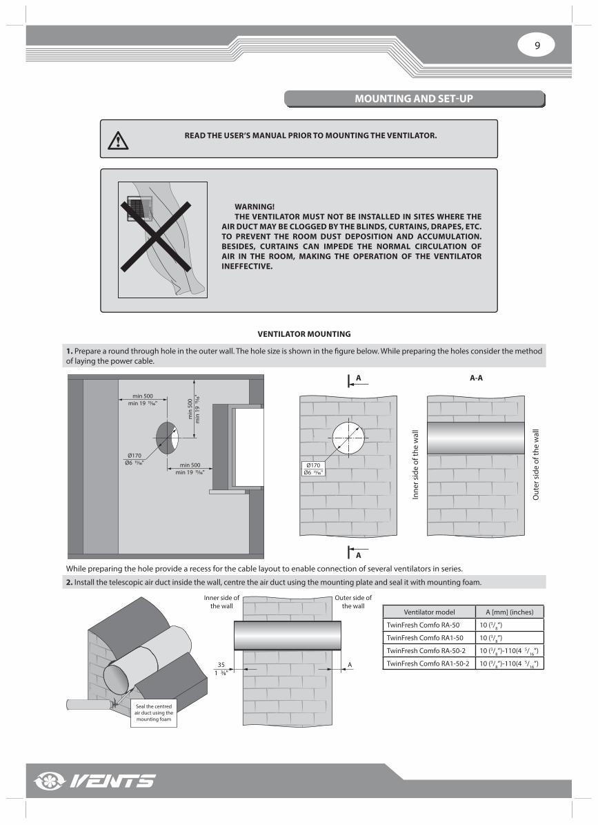
READ THE USER’S MANUAL PRIOR TO MOUNTING THE VENTILATOR.
WARNING!THE VENTILATOR MUST NOT BE INSTALLED IN SITES WHERE THE
AIR DUCT MAY BE CLOGGED BY THE BLINDS, CURTAINS, DRAPES, ETC. TO PREVENT THE ROOM DUST DEPOSITION AND ACCUMULATION. BESIDES, CURTAINS CAN IMPEDE THE NORMAL CIRCULATION OF AIR IN THE ROOM, MAKING THE OPERATION OF THE VENTILATOR INEFFECTIVE.
VENTILATOR MOUNTING
1. Prepare a round through hole in the outer wall. The hole size is shown in the fi gure below. While preparing the holes consider the method of laying the power cable.
Ø170Ø6 11⁄16"
min 500min 19 11⁄16"
min 500min 19 11⁄16"
min
500
min
19
11⁄16
"
A A-A
A
Ø170Ø6 11⁄16"
Inne
r sid
e of
the
wal
l
Out
er s
ide
of th
e w
all
While preparing the hole provide a recess for the cable layout to enable connection of several ventilators in series.
2. Install the telescopic air duct inside the wall, centre the air duct using the mounting plate and seal it with mounting foam.
351 3⁄8"
A
Inner side of the wall
Outer side of the wall
Seal the centred air duct using the mounting foam
Ventilator model А [mm] (inches)
TwinFresh Comfo RA-50 10 (3/8’’)
TwinFresh Comfo RA1-50 10 (3/8’’)
TwinFresh Comfo RA-50-2 10 (3/8’’)-110(4 5/16’’)
TwinFresh Comfo RA1-50-2 10 (3/8’’)-110(4 5/16’’)
www.ventilation-system.com10
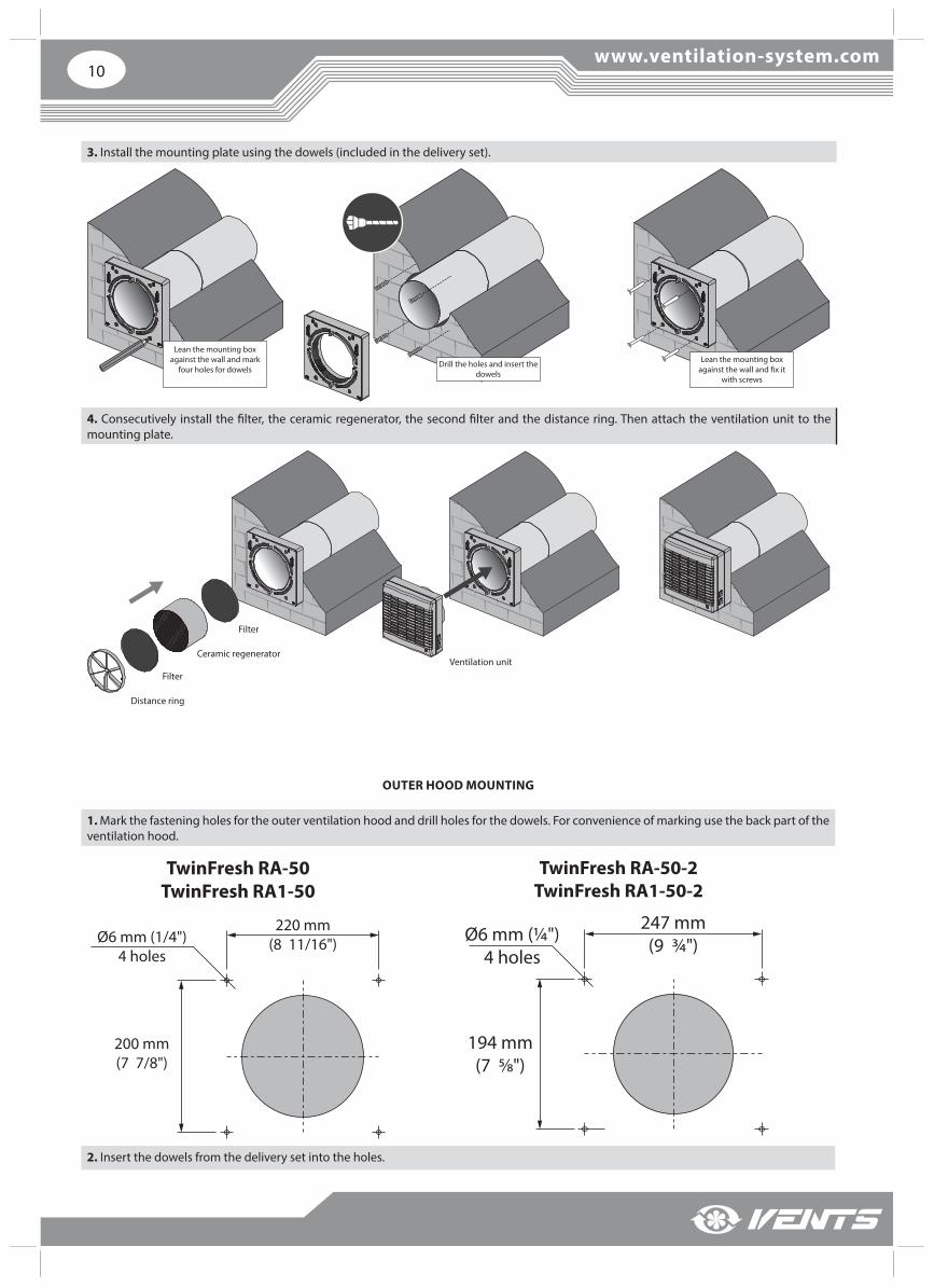
3. Install the mounting plate using the dowels (included in the delivery set).
Lean the mounting box against the wall and mark
four holes for dowelsLean the mounting box
against the wall and fix it with screws
Drill the holes and insert the dowels
4. Consecutively install the fi lter, the ceramic regenerator, the second fi lter and the distance ring. Then attach the ventilation unit to the mounting plate.
Filter
Distance ring
Ceramic regeneratorVentilation unit
Filter
OUTER HOOD MOUNTING
1. Mark the fastening holes for the outer ventilation hood and drill holes for the dowels. For convenience of marking use the back part of the ventilation hood.
200 mm (7 7/8")
Ø6 mm (1/4")4 holes
220 mm (8 11/16")
TwinFresh RA-50TwinFresh RA1-50
194 mm(7 5⁄8")
Ø6 mm (¼")4 holes
247 mm(9 ¾")
TwinFresh RA-50-2TwinFresh RA1-50-2
2. Insert the dowels from the delivery set into the holes.
11
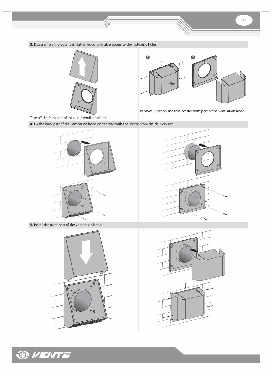
3. Disassemble the outer ventilation hood to enable access to the fastening holes.
Take off the front part of the outer ventilation hood.
1 2
Remove 5 screws and take off the front part of the ventilation hood.
4. Fix the back part of the ventilation hood on the wall with the screws from the delivery set.
5. Install the front part of the ventilation hood.
www.ventilation-system.com12
CONNECTION TO POWER MAINS
DISCONNECT THE VENTILATOR FROM POWER MAINS PRIOR TO ANY ELECTRIC INSTALLATION OPERATIONS.
CONNECTION OF THE UNIT TO POWER MAINS IS ALLOWED BY A QUALIFIED ELECTRICIAN WITH A WORK PERMIT FOR THE ELECTRIC UNITS UP TO 1000 V AFTER CAREFUL READING OF THE PRESENT USER’S MANUAL.
THE RATED ELECTRICAL PARAMETERS OF THE UNIT ARE GIVEN ON THE MANUFACTURER’S LABEL. ANY TAMPERING WITH THE INTERNAL CONNECTIONS IS PROHIBITED AND WILL VOID THE WARRANTY.
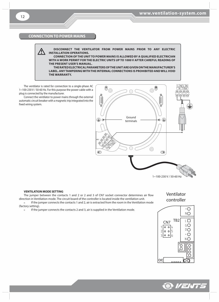
The ventilator is rated for connection to a single-phase AC 1~100-230 V / 50-60 Hz. For this purpose the power cable with a plug is connected by the manufacturer.
Connect the ventilator to power mains through the external automatic circuit breaker with a magnetic trip integrated into the fi xed wiring system.
LN
InL
NOut
L NIn
L NOut
1~100-230 V / 50-60 Hz
Ground terminals
L
N
GD+
+
N
L
N
GD+
+
N
Ventilator controller
TB2CN7123
456
VENTILATION MODE SETTINGThe jumper between the contacts 1 and 2 or 2 and 3 of CN7 socket connector determines air fl ow
direction in Ventilation mode. The circuit board of the controller is located inside the ventilation unit. If the jumper connects the contacts 1 and 2, air is extracted from the room in the Ventilation mode
(factory setting). If the jumper connects the contacts 2 and 3, air is supplied in the Ventilation mode.
13
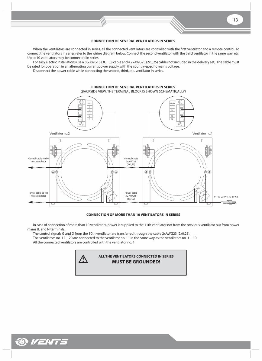
CONNECTION OF SEVERAL VENTILATORS IN SERIES
When the ventilators are connected in series, all the connected ventilators are controlled with the fi rst ventilator and a remote control. To connect the ventilators in series refer to the wiring diagram below. Connect the second ventilator with the third ventilator in the same way, etc. Up to 10 ventilators may be connected in series.
For easy electric installations use a 3G AWG18 (3G 1,0) cable and a 2xAWG23 (2х0,25) cable (not included in the delivery set). The cable must be rated for operation in an alternating current power supply with the country-specifi c mains voltage.
Disconnect the power cable while connecting the second, third, etc. ventilator in series.
CONNECTION OF SEVERAL VENTILATORS IN SERIES (BACKSIDE VIEW, THE TERMINAL BLOCK IS SHOWN SCHEMATICALLY)
Input
LG-DN
Output
LG-DN
Ventilator no.2
Input
LG-DN
Output
LG-DN
Input
LG-DN
Output
LG-DN
Ventilator no.1
Control cable2xAWG23(2х0,25)
Control cable to the next ventilator
Power cable3G AWG18
(3G 1,0)
Power cable to the next ventilator 1~100-230 V / 50-60 Hz
In case of connection of more than 10 ventilators, power is supplied to the 11th ventilator not from the previous ventilator but from power mains (L and N terminals).
The control signals G and D from the 10th ventilator are transferred through the cable 2xAWG23 (2х0,25).The ventilators no. 12…20 are connected to the ventilator no. 11 in the same way as the ventilators no. 1…10. All the connected ventilators are controlled with the ventilator no. 1.
CONNECTION OF MORE THAN 10 VENTILATORS IN SERIES
ALL THE VENTILATORS CONNECTED IN SERIES
MUST BE GROUNDED!
www.ventilation-system.com14
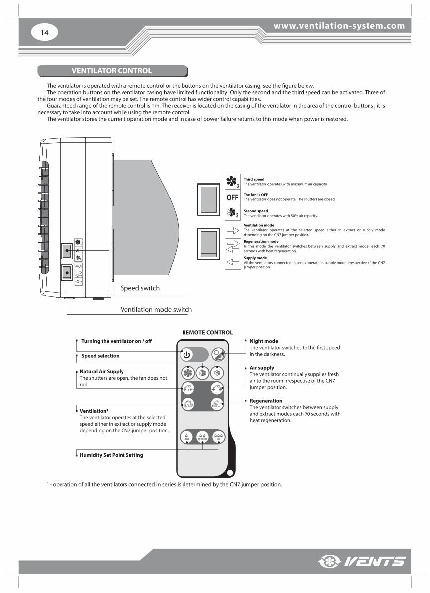
VENTILATOR CONTROL
The ventilator is operated with a remote control or the buttons on the ventilator casing, see the fi gure below.The operation buttons on the ventilator casing have limited functionality: Only the second and the third speed can be activated. Three of
the four modes of ventilation may be set. The remote control has wider control capabilities. Guaranteed range of the remote control is 1m. The receiver is located on the casing of the ventilator in the area of the control buttons , it is
necessary to take into account while using the remote control.The ventilator stores the current operation mode and in case of power failure returns to this mode when power is restored.
Speed switch
Ventilation mode switch
Third speedThe ventilator operates with maximum air capacity.
Ventilation modeThe ventilator operates at the selected speed either in extract or supply mode depending on the CN7 jumper position.
The fan is OFFThe ventilator does not operate. The shutters are closed.
Regeneration mode In this mode the ventilator switches between supply and extract modes each 70 seconds with heat regeneration.
Second speedThe ventilator operates with 50% air capacity.
Supply modeAll the ventilators connected in series operate in supply mode irrespective of the CN7 jumper position.
1 - operation of all the ventilators connected in series is determined by the CN7 jumper position.
Turning the ventilator on / off
Speed selection
Natural Air SupplyThe shutters are open, the fan does not run.
Night mode The ventilator switches to the first speed in the darkness.
Air supplyThe ventilator continually supplies fresh air to the room irrespective of the CN7 jumper position.
RegenerationThe ventilator switches between supply and extract modes each 70 seconds with heat regeneration.
Ventilation1The ventilator operates at the selected speed either in extract or supply mode depending on the CN7 jumper position.
Humidity Set Point Setting
REMOTE CONTROL

15
REMOTE CONTROL
Set the speed switch to position and the ventilation mode switch to position to enable remote control of the ventilation unit.1. Turning the ventilator on / off .
ON/OFF
2. Night mode.
ON/OFF
If the Night mode is activated, the ventilator switches to the fi rst speed in the darkness when the light is turned off . Activation of the Night mode is confi rmed by a long sound signal. Exiting the Night mode is confi rmed by a short sound signal.3. Speed selection.
First speed.
Second speed.
Third speed.
4. Operation mode.
Natural Air Supply mode. The room is ventilated in the natural way, the fan is off .
Air Supply mode. Air is supplied to the room at a set speed. All ventilators connected in series operate in air supply mode no matter of CN7 jumper position.
Ventilation mode. Air is extracted (factory setting) or supplied at a selected speed. All the ventilators connected in series operate depending on position of CN7 jumper.
Regeneration mode. The ventilator operates 70 seconds in supply mode and then 70 seconds in extract mode with heat regeneration.
5. Humidity Control mode. Humidity control is possible only in Regeneration mode by pressing one of the buttons that allow to select the humidity set point.In the Humidity Control Mode the ventilator measures the humidity of the extract air. If the humidity exceeds the selected set point the ventilator switches to a higher speed. After reaching the required level of humidity the ventilator switches to a lower speed. Press one of the speed switches to deactivate the Humidity Control mode.
Setting humidity set point - 45%.
Setting humidity set point - 55%.
Setting humidity set point – 65%.
HUMIDITY CONTROL MAY BE ACTIVATED WITH THE REMOTE CONTROL ONLY!

www.ventilation-system.com16
TECHNICAL MAINTENANCE
DISCONNECT THE VENTILATOR FROM POWER MAINS PRIOR TO ANY MAINTENANCE OPERATIONS WITH
THE UNIT.
Maintenance of the ventilator means regular cleaning of the ventilator surfaces of dust and cleaning or replacement of the fi lters.
VENTILATOR MAINTENANCE
1. Fan inspection (once per year).
Take off the ventilation unit and clean the fan blades. To remove dust use a soft brush, cloth or a vacuum cleaner. Do not use water, abrasive detergents, solvents, sharp objects. Clean the impeller blades once a year.
Remove the ventilation unit Clean the impeller blades
2. Regenerator and fi lter maintenance (3-4 times per year).
1. Remove the air fl ow rectifi er.2. Remove the fi lter upstream of the regenerator.3. Pull the specially designed cord to remove the
regenerator from the air duct.4. Be careful while removing the regenerator to
avoid its damage. 5. Remove the fi lter downstream of the
regenerator.
Filter
Distance ring
Ceramic regenerator
Filter
Clean the fi lters as they get soiled, but not less than once in three months.• After 90 days of operation the ventilator
generates a sound signal after which it is necessary to switch off the ventilator and to replace or clean the fi lters.
• Wash the fi lters and let them get dry. Install dry fi lters in the air duct.
• Vacuum cleaning is allowed. • The fi lter rated service life is 3 years.• For new fi lters contact the Seller.
17
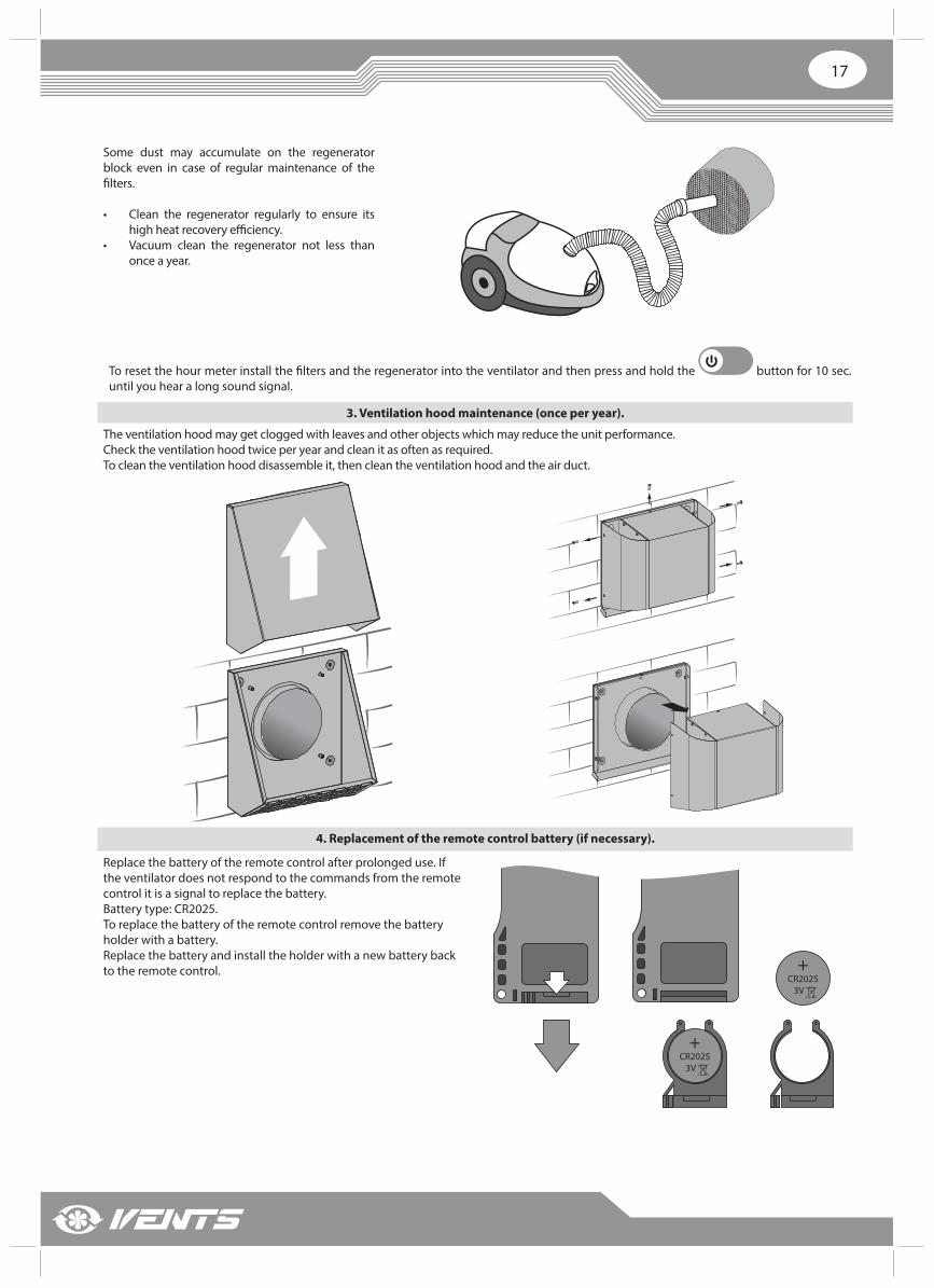
Some dust may accumulate on the regenerator block even in case of regular maintenance of the fi lters.
• Clean the regenerator regularly to ensure its high heat recovery effi ciency.
• Vacuum clean the regenerator not less than once a year.
To reset the hour meter install the fi lters and the regenerator into the ventilator and then press and hold the button for 10 sec. until you hear a long sound signal.
3. Ventilation hood maintenance (once per year).
The ventilation hood may get clogged with leaves and other objects which may reduce the unit performance. Check the ventilation hood twice per year and clean it as often as required.To clean the ventilation hood disassemble it, then clean the ventilation hood and the air duct.
4. Replacement of the remote control battery (if necessary).
Replace the battery of the remote control after prolonged use. If the ventilator does not respond to the commands from the remote control it is a signal to replace the battery. Battery type: CR2025.To replace the battery of the remote control remove the battery holder with a battery. Replace the battery and install the holder with a new battery back to the remote control.
+CR2025 3V
+CR2025 3V
www.ventilation-system.com18
FAULT HANDLING
STORAGE AND TRANSPORTATION REGULATIONS
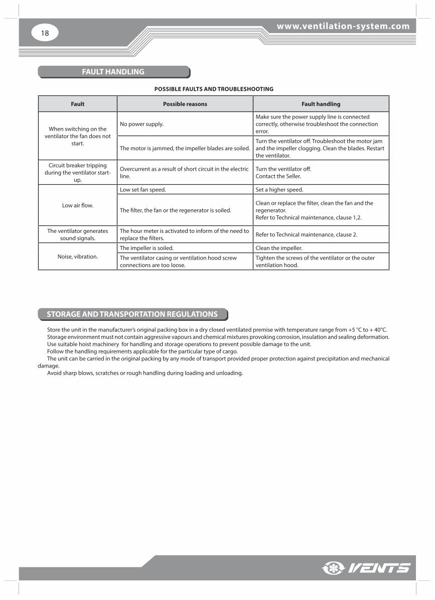
POSSIBLE FAULTS AND TROUBLESHOOTING
Fault Possible reasons Fault handling
When switching on the ventilator the fan does not
start.
No power supply.Make sure the power supply line is connected correctly, otherwise troubleshoot the connection error.
The motor is jammed, the impeller blades are soiled.Turn the ventilator off . Troubleshoot the motor jam and the impeller clogging. Clean the blades. Restart the ventilator.
Circuit breaker tripping during the ventilator start-
up.
Overcurrent as a result of short circuit in the electric line.
Turn the ventilator off .Contact the Seller.
Low air fl ow.
Low set fan speed. Set a higher speed.
The fi lter, the fan or the regenerator is soiled.Clean or replace the fi lter, clean the fan and the regenerator. Refer to Technical maintenance, clause 1,2.
The ventilator generates sound signals.
The hour meter is activated to inform of the need to replace the fi lters. Refer to Technical maintenance, clause 2.
Noise, vibration.The impeller is soiled. Clean the impeller.
The ventilator casing or ventilation hood screw connections are too loose.
Tighten the screws of the ventilator or the outer ventilation hood.
Store the unit in the manufacturer’s original packing box in a dry closed ventilated premise with temperature range from +5 °C to + 40°C. Storage environment must not contain aggressive vapours and chemical mixtures provoking corrosion, insulation and sealing deformation. Use suitable hoist machinery for handling and storage operations to prevent possible damage to the unit. Follow the handling requirements applicable for the particular type of cargo. The unit can be carried in the original packing by any mode of transport provided proper protection against precipitation and mechanical
damage. Avoid sharp blows, scratches or rough handling during loading and unloading.
19
MANUFACTURER’S WARRANTY
FOLLOWING THE REGULATIONS STIPULATED HEREIN WILL ENSURE A LONG AND TROUBLE-FREE OPERATION OF THE UNIT.
USERS’ WARRANTY CLAIMS SHALL BE SUBJECT TO REVIEW ONLY UPON PRESENTATION OF THE UNIT, THE PAYMENT DOCUMENT AND THE USER’S MANUAL
WITH THE PURCHASE DATE STAMP.
Production meets standard operating requirements in the USA and Canada.VENTS US warrants to the original purchaser of the TwinFresh Comfo RA-50 / RA1-50 / RA-50-2 / RA1-50-2 unit that it will be free from
defects in materials or workmanship for a period of 60 months from the date of original purchase. The VENTS US warrants to the original purchaser of the TwinFresh Comfo RA-50 / RA1-50 / RA-50-2 / RA1-50-2 unit that the integrated
control unit will be free from defects in materials and workmanship for a period of 24 months from the date of original purchase.
During the stated warranty period, VENTS US will, at its option, repair or replace, without charge, any product or part which is found to be defective under normal use and service. This warranty does not cover (a) normal maintenance and normal service or (b) any products or parts which have been subject to misuse, negligence, accident, improper maintenance or repair (other than by VENTS US), faulty installation or installation contrary to recommended installation instructions. Labor to remove and replace products is not covered.
The duration of any implied warranty is limited to the time period specifi ed for the express warranty. Some states do not allow limitations on how long an implied warranty lasts, so the above limitation may not apply to you.
VENTS US OBLIGATION TO REPAIR OR REPLACE, AT VENTS US OPTION, SHALL BE THE PURCHASER’S SOLE AND EXCLUSIVE REMEDY UNDER THIS WARRANTY. VENTS US SHALL NOT BE LIABLE FOR INCIDENTAL, CONSEQUENTIAL OR SPECIAL DAMAGES ARISING OUT OF OR IN CONNECTION WITH PRODUCT USE OR PERFORMANCE.
THERE ARE NO OTHER WARRANTIES, EXPRESS OR IMPLIED, INCLUDING, BUT NOT LIMITED TO, IMPLIED WARRANTIES OF MERCHANTABILITY OR FITNESS FOR A PARTICULAR PURPOSE.
Some states do not allow the exclusion or limitations of incidental or consequential damages, so the above limitation or exclusion may not apply to you. This warranty gives you specifi c legal rights, and you may also have other rights which vary from state to state. This warranty supersedes all prior warranties.
If proof of sales date is absent, warranty period is calculated from the production date. The unit can be exchanged at the following address:Bodor Vents, LLC DBA: Vents-US11013 Kenwood Road Cincinnati, Ohio 45242Phone: (513)348-3853e-mail: [email protected]

www.ventilation-system.com20
Seller
Address
Phone Number
Purchase Date
Seller’s Stamp
Unit Type Single-room reversible energy regeneration ventilator
Model TwinFresh Comfo _________________
Serial Number
Manufacture Date
Production meets standard operating requirements in the USA and Canada.
Quality Inspector’s Stamp
This is to certify acceptance of the complete ventilator delivery with the user’s manual. The warranty terms are acknowledged and accepted.
Customer’s Signature
The single-room reversible energy regeneration ventilator TwinFresh Comfo _________ has been connected to power mains pursuant to the requirements stated in the present user’s manual.
Company Name
Address
Phone Number
Installation Technician's Full Name
Installation Date: Signature: Installation Company Stamp
The ventilator has been installed in accordance with the provisions of all the applicable local and national construction, electrical and technical codes and standards. The ventilator operates normally as intended by the manufacturer.
Signature:
ACCEPTANCE CERTIFICATE
SELLER INFORMATION
INSTALLATION CERTIFICATE
21
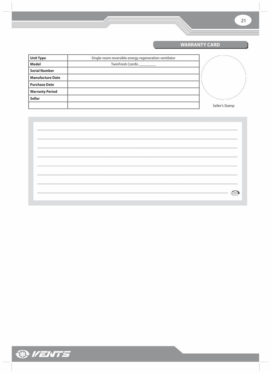
Unit Type Single-room reversible energy regeneration ventilator
Model TwinFresh Comfo _________
Serial Number
Manufacture Date
Purchase Date
Warranty Period
Seller
Seller’s Stamp
___________________________________________________________________________________________________________
___________________________________________________________________________________________________________
___________________________________________________________________________________________________________
___________________________________________________________________________________________________________
___________________________________________________________________________________________________________
___________________________________________________________________________________________________________
___________________________________________________________________________________________________________
______________________________________________________________________________________________________
WARRANTY CARD

2015 (V91EN-01(USA_120)