
Testing Medical Device and Package · PDF fileTesting Medical Device and Package Integrity...
18
Testing Medical Device and Package Integrity Authors: Michael Franks, Stephen Franks - T.M. Electronics, Inc. 1999 Table of Contents Introduction: Objective Medical Device Testing: Step 1 – Process Validation Planning Step 2 - Choosing the Testing Methodologies Leak Integrity Testing Methods Flow Integrity Testing Methods Step 3a - Pressure Decay Leak and Mass Flow Testing Pressure Decay Leak Testing Specifications Mass Flow Testing for Leakage Step 3b - Mass Flow Testing for Obstructions Mass Flow Testing Step 4 - Product Assurance Package Validation Testing: Step 1 – Package Validation Planning Step 2 – Choosing the Package Testing Methodologies Tensile Seal Strength Testing Inflation Seal Strength Step 3a. Inflation Test Specifications Burst Testing Creep Testing Creep to Failure Testing Step 3b. Pressure Decay Leak Testing Step 4. Package Assurance Conclusion References Introduction Objective When a manufacturing firm produces a product designated for use in the medical field, the company must supply one element regardless of part design: assurance. Through the use of in-line product testing and final package testing, a manufacturer can document the steps taken to assure the end user that the product has been examined and has passed the standard testing procedures designated by organizations such as the Food and Drug Administration (FDA), International Standards Organization (ISO), and American Society for Testing and Materials (ASTM). A quality control department, therefore, must
Transcript of Testing Medical Device and Package · PDF fileTesting Medical Device and Package Integrity...

Testing Medical Device and Package Integrity Authors: Michael Franks, Stephen Franks - T.M. Electronics, Inc. 1999 Table of Contents Introduction: Objective Medical Device Testing: Step 1 – Process Validation Planning Step 2 - Choosing the Testing Methodologies Leak Integrity Testing Methods Flow Integrity Testing Methods Step 3a - Pressure Decay Leak and Mass Flow Testing Pressure Decay Leak Testing Specifications Mass Flow Testing for Leakage Step 3b - Mass Flow Testing for Obstructions Mass Flow Testing Step 4 - Product Assurance Package Validation Testing: Step 1 – Package Validation Planning Step 2 – Choosing the Package Testing Methodologies Tensile Seal Strength Testing Inflation Seal Strength Step 3a. Inflation Test Specifications Burst Testing Creep Testing Creep to Failure Testing Step 3b. Pressure Decay Leak Testing Step 4. Package Assurance Conclusion References Introduction Objective When a manufacturing firm produces a product designated for use in the medical field, the company must supply one element regardless of part design: assurance. Through the use of in-line product testing and final package testing, a manufacturer can document the steps taken to assure the end user that the product has been examined and has passed the standard testing procedures designated by organizations such as the Food and Drug Administration (FDA), International Standards Organization (ISO), and American Society for Testing and Materials (ASTM). A quality control department, therefore, must

be aware of different testing methodologies in order to gain this control and assurance over the production and packaging processes. This report examines different product and package testing procedures, focusing on the pressure decay leak and mass flow tests for product integrity and seal strength and pressure decay leak testing for package integrity. By implementing pressure decay leak testing, mass flow testing, and seal strength testing to a quality control system, a manufacturer of medical devices will gain control over their manufacturing process, and therefore gain quality assurance in the field. Medical Device Testing
Figure 1. The Medical Device Testing Process This figure represents the process followed when testing the leak and flow integrity of a medical device. This section analyzes each step of this chart, providing details as to the procedures and requirements for each step.
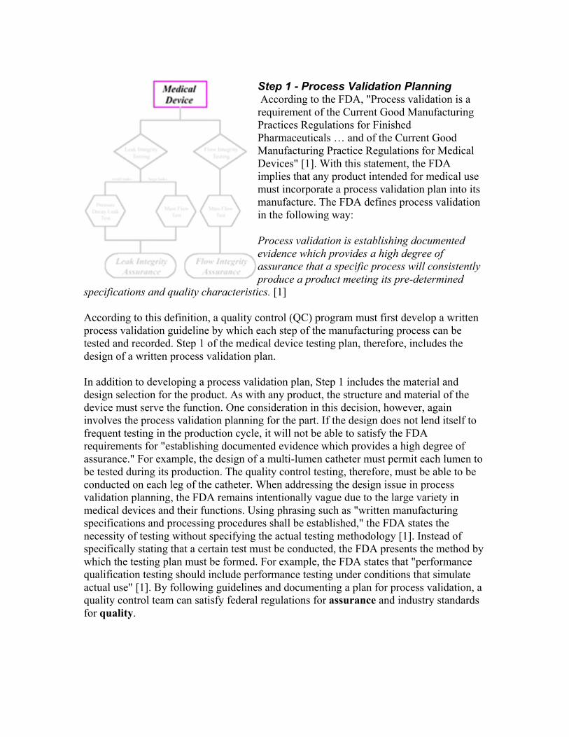
Step 1 - Process Validation Planning According to the FDA, "Process validation is a requirement of the Current Good Manufacturing Practices Regulations for Finished Pharmaceuticals … and of the Current Good Manufacturing Practice Regulations for Medical Devices" [1]. With this statement, the FDA implies that any product intended for medical use must incorporate a process validation plan into its manufacture. The FDA defines process validation in the following way: Process validation is establishing documented evidence which provides a high degree of assurance that a specific process will consistently produce a product meeting its pre-determined
specifications and quality characteristics. [1] According to this definition, a quality control (QC) program must first develop a written process validation guideline by which each step of the manufacturing process can be tested and recorded. Step 1 of the medical device testing plan, therefore, includes the design of a written process validation plan. In addition to developing a process validation plan, Step 1 includes the material and design selection for the product. As with any product, the structure and material of the device must serve the function. One consideration in this decision, however, again involves the process validation planning for the part. If the design does not lend itself to frequent testing in the production cycle, it will not be able to satisfy the FDA requirements for "establishing documented evidence which provides a high degree of assurance." For example, the design of a multi-lumen catheter must permit each lumen to be tested during its production. The quality control testing, therefore, must be able to be conducted on each leg of the catheter. When addressing the design issue in process validation planning, the FDA remains intentionally vague due to the large variety in medical devices and their functions. Using phrasing such as "written manufacturing specifications and processing procedures shall be established," the FDA states the necessity of testing without specifying the actual testing methodology [1]. Instead of specifically stating that a certain test must be conducted, the FDA presents the method by which the testing plan must be formed. For example, the FDA states that "performance qualification testing should include performance testing under conditions that simulate actual use" [1]. By following guidelines and documenting a plan for process validation, a quality control team can satisfy federal regulations for assurance and industry standards for quality.

Step 2 - Choosing the Testing Methodologies In addition to part design and material selection, forming a process validation plan includes the selecting of a testing methodology during the production process. As Step 2 demonstrates, leak integrity testing and flow integrity testing encompass the two main categories of product testing. As the next section explains, leak integrity testing includes many different methods, depending on the requirements and scope of the project. Flow integrity testing, however, only includes one essential technique - the mass flow test. By sthe intended design and function of the test part,
integrity validation tests may be chosen to best suit the needs of the process validationplan.
tudying
Leak Integrity Testing Methods Leak integrity testing includes many different applications, ranging from a crude bubble test to a complex helium mass spectrometry test. Before the leak testing methods are analyzed, however, leak testing itself must be defined. According the Gary Elder, president of Gary Elder & Associates, a medical device testing firm, leak testing "is the evaluation of a component or system to locate leaks or to measure how much leakage will occur over a certain period of time" [2]. Extending this definition, C.N. Sherlock, author of the Nondestructive Testing Handbook lists three basic reasons for leak testing:
To prevent material leakage loss, which interferes with system operation To prevent environmental contamination hazards or nuisances caused by
accidental leakage To detect unreliable components and those whose leakage rates exceed acceptable
standards [3] From these definitions, as well as from Elder’s comment that leak testing should "assure product performance criteria are met," a manufacturer can conclude that leak testing is a procedure that could satisfy the need for a standard quality control methodology [2]. In his article "Leak Testing, A Quality Assurance NDT Method," Elder clearly outlines the procedures necessary to create this type of leak testing process plan. This process begins by defining the leak test specifications, then proceeds to defining the leak test procedure, and finally ends the operation with the analysis of the leak test’s performance [2]. Before beginning this process, however, the methodologies of different leak testing procedures

must be understood in order to make an informed decision as to which leak test to choose. The first leak test method developed was the bubble test. A crude operation, bubble testing involves inflating a part and submerging it into a liquid bath. While submerged, a highly trained operator makes subjective judgments as to the location and leak rate of the bubbles emanating from the part. If the part passes the quality control standards for an acceptable part, the piece must then be removed from the bath and allowed to air dry before further processing or testing may be conducted on this part. Problems involved in this method include imprecise leak rate data and a potential for Type II error (accepting a part when it is unacceptable) due to fluid molecules blocking the hole in the part, thereby displaying little or no leakage. Also, the minimum detectable leakage rate for bubble testing is 10-5 Pa⋅ m3/s [2], making this the least accurate of leak testing methods. Another leak test, helium mass spectrometry, involves the detection of helium molecules that have moved from the high concentration helium environment inside the part to the outside atmosphere. This process involves pressurizing the test part with a helium mixture inside an airtight pressure chamber. The air is then evacuated from the chamber, creating a pressure gradient between the internal volume of the part and the vacuum. This difference invites the helium molecules to move out of the part through any areas of leakage. A mass spectrometer then samples the air inside the chamber and checks for helium. The amount of helium detected is then translated into a leakage rate for that part. The sensitivity of helium testers arises from the fact that the helium molecule itself is smaller than other air component gases (e.g. oxygen and nitrogen) [4]. Since this particle is smaller, most occlusions that would normally block a larger molecule will permit the passage of the helium molecule. Although helium testing is one the most highly sensitive testing methods (detects leakage rates as small as 10-12 Pa⋅ m3/s in a vacuum), the test equipment is relatively expensive and complex to use. As an alternative to the gas check method presented above, pressure differential testing provides an inexpensive, straightforward method for testing leakage of medical devices. One technique used in this methodology is pressure decay leak testing. A pressure decay test involves the initial inflation of a test part and the establishment of a reference pressure. After a user-designated amount of time, the pressure is then measured again, and this second measurement is compared to the reference pressure. The change is pressure in the test part can then be used to calculate the leak rate, given the internal volume of the device. Because of this test methodology, an advantage of this method is the accuracy and repeatability of the test. Much like pressure decay testing, mass flow testing for leakage uses a pressure differential to measure the "gross" leak rate. In this method, the test part is first initialized (inflated). After the part is fully inflated, any pressure change measured by the pressure sensor is compensated for by inputting air into the test part. The amount of air that enters the test part is measured by the flow sensor, which then directly determines the leak rate of the part. Compared to pressure decay leak testing, mass flow testing is less accurate when testing for occlusion defects. Pressure decay sensing is able to detect minute

changes in pressure, while a flow sensor will only detect airflow movement due to large occlusions in the part. Later sections of this report detail the procedure and mechanics involved in pressure decay leak and mass flow testing for leak integrity. To obtain more information on alternate forms of leak testing, Elder’s article and Sherlock’s book are recommended.
Type of Leak Test
Minimum Detectable Leak Rate
Advantages Disadvantages
Bubble Test 10-5 Pa⋅ m3/s
Inexpensive, indicates leak location
Requires skilled operator, no determination of leak rate
Mass Flow Test Time limited
Determines leak rate directly, fast test (1-2 seconds)
Only detects gross leaks due to accuracy of flow meter
Pressure Decay Test Time limited Repetitive, accurate Sensitivity limited
by size of part
Helium Mass Spectrometry 10-12 Pa⋅ m3/s Highly sensitive Expensive,
complex
Various leak testing methodologies [3] Flow Integrity Testing Methods Unlike leak integrity testing, testing for obstructions in an open-ended test part normally involves the use of one test: the mass flow test. Mass flow testing is often used to detect large occlusions in a medical device. This test, however, is most often used to check the flow integrity of a product. Flow integrity is the ability of a fluid to pass through the test part without obstruction. In medical devices, such as catheters or tubing, this condition is tremendously significant in that flow creates the functionality of the product. If the manufacturing process creates a part that becomes blocked or crimped, the passage of the necessary fluid, whether it is water, air, or blood, will become impeded and the part will be useless. Mass flow testing involves passing air through a test part at a constant pressure. After the part is initialized, the air passes a flow sensor as it enters the part.

Since the air is supplied at a constant pressure, any deviation from the acceptable flow rate will indicate an obstruction. Once an operator has indicated the flow rate limits for the test part, the part is tested in a pass/fail operation.
Step 3a - Pressure Decay Leak and Mass Flow Testing The previous sections of this report outlined different leak and flow testing strategies, and some advantages of each. In Step 3 of the Medical Device Testing process, the specific tests are chosen, parameters are established, and tests are performed. This section details the background of pressure decay testing and mass flow testing, as well as presents general schematic models of these tests.
Pressure Decay Leak Testing Specifications Pressure decay leak testing theory is based on the fundamental gas law,
, where P represents pressure, V represents volume, n is the number of moles of air, R is the universal gas constant, and T represents temperature. Once the test has begun and the test part has been initialized, the part has an initial volume, temperature, and pressure. During the test, the temperature in the test part is constant. Since leak rate is the change in volume per unit of time, the change in volume for the test part must be determined. In a pressure decay leak test, the pressure sensor measures the change in pressure. Using the gas law, therefore, volume is determined using the following equation:
. By calculating the number of moles of air in the test part volume, as well as using the ambient temperature of the system, the volume change may be calculated by using the measured change in pressure. Dividing the change in volume by the time taken for the test, therefore, determines the leak rate for the test part. When determining the tolerance levels in a medical device, the operator must "reverse engineer" the settings for the test. After designing the product, the quality control department must designate acceptable leakage rates for the part. In order to use this information, however, the testing engineer must convert this leak rate to a change in pressure by using the reverse of the method shown above; by using the leak rate, the engineer must first decide on the time length of the test. Using this information, the

operator can then set the tolerance limits for the pressure decay leak test using the following form of the gas law:
, where t is the time of the test (since the leak rate is ∆ V/t), and the pressure is set according to quality control standards for the part. The adjacent figure depicts a typical schematic for a pressure decay assembly. Air enters from the air supply tube directly into the pressure regulator. From here, the air passes through "V2," a bleed valve used to dissipate air after the completion of the test. At this
point in the test, the valve does not allow any air to escape. The air then passes through the port valve, "V3." This valve will close once the test part has been inflated to the correct pressure. As the air enters the test part, a transducer, "S," measures the pressure of the air in the test part and converts this measurement into an electronic signal. Once the test part has been fully inflated, or charged, V3 closes. Any change in pressure due to a leak in the test part is measured by the transducer and reported to the microprocessor. After the test has reached the maximum test time, V3 opens and V2 allows the excess air to bleed
into the environment. To illustrate the results of a pressure decay leak test graphically, Figure 6 presents the data screen from the T.M. Electronics MDT-500 Leak and Flow tester. The curve represents the pressure versus time comparison of the test part. In this test, the pressure, measured in psig, is compared to time, measured in seconds. After the initial inflation, the pressure in the part begins to decrease. If the pressure loss in the part exceeds operator indicated tolerance levels, then the part will fail. If the pressure decay remains within acceptable designated limits, the part will pass the test.

Mass Flow Testing for Leakage
Much like pressure decay leak testing, mass flow testing operates as a function of pressure. Macroscopically, mass flow testing for leakage, unlike pressure decay leak testing, measures the speed, or flow, of any air that passes into a closed-end test part. Figure 7 represents a simple schematic of mass flow operation. As with leak testing, the air passes directly from the supply into the manually controlled pressure regulator. From here, the air passes through the flow valve "V1", the flow sensor "FS" and another flow valve "V2." From here, the air enters the product directly. As the air enters the test part, a transducer, labeled as
pressure sensor "PS", measures the pressure of the air entering the part in order to validate the correct pressure established by the manual pressure regulator. Once the part has been fully pressurized, the flow sensor measures any air movement through the part. If the flow sensor detects any air motion, this measurement is then calculated, designated the flow rate, and sent to the microprocessor for analysis and display. Microscopically, many flow sensors operate on the basis of heat transfer. The next figure represents a typical flow sensor assembly. Initially, the supply passes air through the flow sensor until the test part has been pressurized. Once this is complete, the regulator continues to attempt to pass air through the sensor. If a leak exists in the test part, air will enter the flow sensor at the inlet. The air temperature is measured using a precision micro-thermister, "MT1." Next, as the air continues to pass through the flow sensor assembly, the air is heated by a heating element to a temperature above the ambient temperature as measured by the micro-thermister "MT3." As the air exits the flow valve, an exiting micro-thermister measures the temperature of the air. The change in temperature from MT1 to MT2 is then calculated. In order to calculate the flow value of the air, the microprocessor applies the principle that the heat in the moving air is transferred in proportion to the amount of moving air. Any air movement calculated using the flow sensor, therefore, indicates a flow of air through a leak in the test part.

Step 3b - Mass Flow Testing for Obstructions
Unlike mass flow testing for leakage, mass flow testing for obstructions uses a continual flow model to calculate the blockage in an open-ended device. A device such as a catheter must be tested for obstructions before it can be considered a good part. The following sections detail the procedures followed in order to perform a mass flow test to determine if a part is obstructed. Mass Flow Obstruction Testing As mentioned above, a mass flow test for obstructions operates on the model of continual flow. As Figure 10 shows, a reprint of Figure 7, the schematic setup of the two mass flow tests is identical. An air supply inputs air through the
regulator at an operator-designated pressure. The air then passes though the first flow valve "V1," the flow sensor "FS," and the second flow valve "V3" before passing into the test part. Once the pressure sensor has indicated that the test part has reached the proper pressure, the flow sensor measures the continuous flow of air through the sensor assembly. In this test, the flow sensor operates in the same manner as the mass flow test for leakage; the amount of heat transferred by the moving air is in proportion to the amount of moving air. This test, however, determines whether a part passes or fails by the flow rate through the part. If the flow sensor measures too low a flow rate at the desired pressure, the part will fail the test. Any obstructions in the part, therefore, will restrict the flow of air through the device, thereby causing the part to fail the test. Step 4 - Product Assurance After product testing has been completed and the results have been documented, the manufacturer has completed the process validation required by the FDA and other standardization organizations. By performing leak testing for the leak integrity of the part, and by performing flow testing for the flow integrity of the part, a manufacturer can provide the end user of their product the assurance that the part provided will be free from defects. The process for complete product integrity, however, does not end athis point. At this point, a manufacturer must be ablto transport this part from the manufacturing floor the user while maintaining a sterile environm
t
eto
ent. To

do this, a firm must provide packaging that has been rigorously tested to assure the consumer that the product will be safe to use. The following flowchart details the next steps in the quest for product integrity: package validation assurance. Package Validation Testing
Step 1 - Package Validation Planning
Unlike medical device production regulation, medical packaging regulation has evolved in recent years into a tightly regulated process involving federal standards and guidelines. Examples of these industry documents include ANSI/AAMI/ISO 11607 "Packaging for Terminally Sterilized Medical Packaging", ASTM F1140 "Test Methods for Failure Resistance of Unrestrained and Nonrigid Packages for Medical Applications", and regulations such as the FDA Quality System Regulation (QSR) practices. According to the FDA QSR Manual, "the package and device should be designed together so that all factors in the product and package system can be considered" [5]. With this statement, the FDA

effectively summarizes the flowchart shown in Figure 13: final product validation must lead into package validation planning. In this first step of the packaging process, therefore, many important decisions must be made in regard to these regulations, including sterilization procedures, material type, and the package shape. When considering the packaging material to be used, an important preconsideration must be made in regard to the sterilization cycle. For example, any type of sterilization that involves gas transmission, such as Ethylene Oxide sterilization, must be performed using a porous material, such as paper or Tyvek©. Conversely, a sterilization procedure that involves radiation, such as gamma radiation sterilization, would not necessitate that the packaging material be porous. ISO 11607 states that "the intention of packaging for terminally-sterilized medical devices is to maintain the sterility of the product with the respect to its intended use, the shelf life, transport and storage conditions" [7]. Simply stated, ISO intends that the material selected with withstand the sterilization and packaging processes, and maintain a sterile barrier for the life of the product. Another aspect of material selection involves the strength requirements for the package. If the product requires a highly durable environment to protect it from damage, a rigid plastic tray may be used. Again, ISO 11607 creates a standard for material selection by necessitating that "specific or minimum physical properties, such as tensile strength, thickness variation, tear resistance, air permeability (porosity), and burst strength, shall be established to meet the requirements of the medical device, packaging and sterilization process or final package" [7]. Once again, this standard creates a codependence of form and function on the material selection, this time incorporating physical strength requirements with the sterilization requirements. Material selection, therefore, depends on both the sterilization methods used to sterilize the part, and the functional requirements for the package. Step 2 - Choosing the Package Testing Methodologies After the material, shape, and size of the package have been determined and developed, the next step in the package validation process involves the selection of testing methodologies to be used in the package testing. Currently, two avenues of testing have developed in package testing: seal strength testing and leak (sterility) integrity testing. ISO 11607 clearly documents the methodology available to perform these types of testing. Section 6.3.2.1 states that "when evaluating whether the package sealing process in under control, it is helpful to look for variations in seal strength values" [7]. Seal strength testing involves testing to assure adequate strength of package seals so that the product sterility is not compromised during its

life [7]. Package integrity testing, documented in Section 6.4.1 of ISO 11607, requires that "the manufacturer … demonstrate the integrity of the sterile package by testing the package. This can be accomplished by physical tests" [7]. One such test is an internal pressure test, such as a pressure decay leak test for non-porous packages. The following sections introduce these different testing methodologies for seal strength and sterile integrity testing and relate them to the overall package validation process. Tensile Seal Strength Testing As mentioned above, tensile seal strength testing measures the ability of a package seal to resist separation. Tensile seal strength testing "measures the strength of a package seal by tensile testing a portion of that seal. It does not measure seam continuity or any other seal properties beyond the force required to test (peel) apart the seal between two materials" [7]. In the definition of tensile seal strength testing, ISO 11607 successfully defines the test, as well as states the test’s limitations. According to Stephen Franks, Executive Vice President of T.M. Electronics, Inc., a device and package testing instrumentation company, "tensile seal strength testing can give a microscopic view of seal strength, but it does not cover the big picture. Sterilization and production processes produce more than simple peel stress, they produce hoop and lateral stress from inflation, as well as non-perpendicular peel stress" [6]. The first step in tensile testing involves separating the package into many small parts with a width of approximately 1 inch. A strip is then loaded into a tensile test machine, such as an Instron© machine, and tested for its tensile strength. This process is repeated for each strip of the bag, creating a definitive picture of the tensile seal strength for that package. Figure 16 demonstrates the stresses involved in tensile strength testing. Notice that the stresses are in one plane only. The force of the tensile test machine is in the horizontal or vertical plane, perpendicular to the seal. As mentioned above, tensile seal strength does provide a detailed account of the seal strength at each point around a package perimeter, but it has its limitations. By only measuring the resistance to peel stress, tensile testing does not accurately portray the true strengths and weaknesses of a package. Tensile seal strength testing, therefore, accurately measures the relative seal strength of specific locations of a package (relative to other points in the package seal), while providing little information as to the resistance of the seals to the stresses of production. Inflation Seal Strength Testing As opposed to tensile seal strength testing, inflation seal strength testing accurately measures the overall reaction of the package seals to inflation stresses such as hoop stress, perpendicular peel stress, and lateral inflation stress. Inflation seal strength testing involves the inflation of a package to a critical point at which the weakest point in the seal will rupture, providing information as to the critical pressure and location for seal weakness. In inflation testing, the seals encounter three different components of stress; the inflation of the package provides peel stress with horizontal and vertical components, tension due to hoop stress in the vertical direction, and lateral stress due to package expansion. If these three stresses are greater than the strength of the seal at any point within the package, the seal will rupture. Inflation seal strength testing provides a more accurate simulation of the packaging and sterilization processes, but it also has limitations. While the stresses encountered in this
test create a more accurate picture of test conditions, they also create a more complicated failure analysis for the package. Instead of isolating each stress and its components, inflation seal strength testing provides an overview of seal strength. Both tensile testing and inflation seal strength testing provide information as to seal strength at different locations in the package, this study details the different methods used in inflation seal strength testing. Although more complicated, inflation testing offers a more realistic representation of the testing conditions and stresses. Step 3a of the package validation procedure involves the implementation of different inflation seal strength tests. For more information about tensile seal strength testing, consult ASTM standard F88 or D903. Leak Integrity Testing In addition to testing for seal strength, a package should also be tested for leak integrity in order to check the sterile barrier property of the package. Discussed at length in the medical device testing section of this report, leak integrity testing for packaging can operate in the same manner. Different leak integrity tests, such as bubble testing, helium mass spectrometry, and pressure differential testing are used on non-porous packages. It is important to note that at this point, leak testing is mainly performed on non-porous packages for the obvious reason - porous packages leak by nature. While equipment exists to test porous packages for leaks, this equipment is generally too expensive and complicated for the average medical packaging firm [8]. However, ISO11607 details various methods that may be used for either porous or non- porous material packages. Pressure decay leak testing non-porous packages, therefore, can determine the sterile integrity of the package seals and material. As with medical devices, pressure decay leak testing will be studied, this time in regard to package integrity testing, in Step 3b of the package validation procedure.
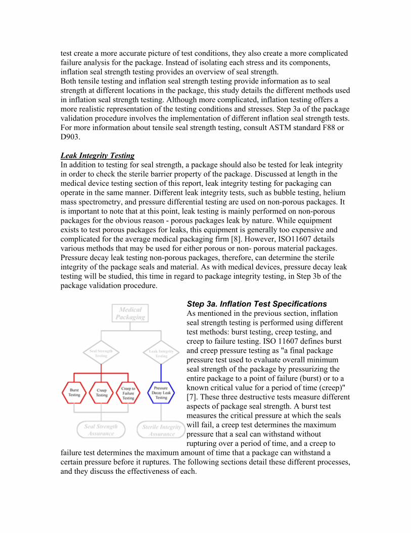
Step 3a. Inflation Test Specifications As mentioned in the previous section, inflation seal strength testing is performed using different test methods: burst testing, creep testing, and creep to failure testing. ISO 11607 defines burst and creep pressure testing as "a final package pressure test used to evaluate overall minimum seal strength of the package by pressurizing the entire package to a point of failure (burst) or to a known critical value for a period of time (creep)" [7]. These three destructive tests measure different aspects of package seal strength. A burst test measures the critical pressure at which the seals will fail, a creep test determines the maximum pressure that a seal can withstand without rupturing over a period of time, and a creep to
failure test determines the maximum amount of time that a package can withstand a certain pressure before it ruptures. The following sections detail these different processes, and they discuss the effectiveness of each.

Burst Testing Burst testing determines the "overall minimum seal strength" of the package seals by inflating the package until it ruptures. This burst pressure directly measures the performance of the seals at the given pressure. Tsection "Inflation Seal Strength Testing" abovereviews the stress analysis of inflation seal strength testing. Stresses such as hoop stress, peel stress, and lateral stress all determine the failure point of the seals during these tests. Figure 18 presents the graphical output of the T.M. Electronics BT-1000 Automated Seal Strength Tester. In this graph, the pressure increases to a maximum pressure at which the pressure drops down to zero. This immediate drop in pressure represents the rupture of the seal. As the graph shows, a burst test is a relatively fast test, normally taking between one and five seconds. An important factor in this time to failure is the flow rate of the air. If a package is inflated too quickly, the seals may be jarred apart, instead of peeled apart. Extensive testing followed by visual inspection of rupture areas should be performed in order to determine the correct flow rate of air into the package.
h
e
Creep Testing Unlike burst testing, creep testing involves the inflation of a package to a certain specific pressure. The point of a creep test, however, is not to rupture the bag, but to test the performance of the seals against a specified pressure for a specified length of time. This test helps to determine the performance of a package when placed under harsh production or sterilization conditions for an extended period of time. ASTM method F1140 suggests the use of 80% of the burst pressure as a starting point to perform the creep test. The length of the test is suggested to be about 30 seconds. These parameters were suggested from empirical tests when the method was developed. Each package should be examined during the validation stage to determine the appropriate testing parameters depending on the materials, bonding types and expected production or sterilization stresses encountered. The creep test is an attribute test and as such is reported as pass or fail. The test does not report quantitative information about seal quality. The test procedure recommends that a visual inspection be performed at the end of the test cycle. An observation of the amount of seal failure is helpful to determine if a change in seal penetration has occurred from previous tests. Seals may typically shear by 10%, but an observation of a 90% seal penetration may indicate that the process is producing weaker seals. As an attribute test, the creep test does not report a quantifiable value. A test to report a related quantifiable value is helpful to report process changes and is amenable to statistical quality control. Such a test is the "Creep to Failure" test. Creep to Failure Testing Unlike creep testing, creep to failure testing measures the time it takes for a package to rupture at a specified pressure. For example, if the given test time is 30 seconds, a creep

to failure test would be used to determine the average "time to failure" during the test cycle at a specified pressure. The failure would be a resulting rupture of the package seals. This test, therefore, uses time as the variable in determining the strength of the package seals. As the "time to failure" shortens, it implies that the seals are becoming weaker or less resistant to shear at the specified pressure. Using statistical tools, such as mean and range control charts, trends for the "time to failure" indicate the direction to weaker or stronger seals as the times shorten or lengthen respectively. The load mechanisms for creep to failure testing are the same as for creep testing. The package is subjected to a constant pressure (load) during the test cycle. Step 3b. Package Leak Testing
As mentioned earlier, the pressure decay leak testing process for packaging follows the same procedure and mechanical processes as the test for leakage in medical devices; an initial pressure in the package is measured against a final pressure, and the change in pressure represents the leakage. Leakage in non-porous packages may be the result of flaws in either the packaging material or the sealing process. One limitation of pressure decay leak testing is the inability of the operator to precisely locate the leakage location in the package. An advantage of pressure decay testing is that very small leaks on the order of 10 um can be detected in a short time.
Completely closed packages present a slightly different test challenge that testing product components with an open access port. Therefore, a specially designed device called a "Package Port" is required to enter the package volume under test. Through this Package Port an inflation probe/ sensor is inserted into the package, the inflation pressure is applied and leaks are sensed. The Package Port is a patented device by T.M. Electronics, Inc., Boylston, MA. Other package integrity tests are available as noted in ISO11607. These methods are non-quantifiable and require operator interpretation. These tests can be applied to either porous or non-porous material packages. The methods are dye penetration, vacuum jar bubble testing, and trace gas testing. Each method requires specific technique and trained expertise to be performed properly.

Step 4. Package Assurance With the completion of Step 3, the manufacturer has reached the final stage of package validation: assurance. After completing and documenting the different seal strength tests and sterile integrity tests, a medical packaging firm can confidently present the final product to the market. The manufacturer can now assure the consumer and the necessary regulatory bodies that the package has withstood the packaging and sterilization process. This knowledge, combined with the assurance that the product contained in the package has passed the necessary testing and documentation psignifies that the medical device production cycle has ended. By documenting each step of
the Medical Device Testing process and Package Validation Process, a manufacturerdemonstrate control over the production and packaging processes.
rocedures,
can
Conclusion Throughout the two previous testing processes, several themes have consistently reappeared, including assurance and control. As this study has shown, these two concepts are interrelated; a manufacturer must prove control in order to create assurance. Thus, a manufacturer must gain control with the testing processes by creating a process validation plan, defining the test methodologies, and documenting the test results. As the Medical Device Testing Flowchart and the Package Validation Testing Flowchart show, each step of the testing process can be easily separated. By creating a procedure for the process formation, a manufacturer can gain the necessary control over the production process, thereby providing assurance to the consumers that the product and package are free from defects and are of the highest quality possible.

References [1] "Guideline on General Principles of Process Validation," U.S. Food and Drug Administration Center for Drug Evaluation and Research, [Online] May, 1987. Available: Food and Drug Administration: Center for Drug Evaluation and Research, http://www.fda.gov/cder/guidance/pv.htm. [2] G. Elder, "Leak Testing, A Quality Assurance NDT Method," ASTM Standardization News, Jan. 1995. [3] C.N. Sherlock, Nondestructive Testing Handbook, Vol. 1: Leak Testing (R.C. McMaster, editor), American Society for Nondestructive Testing, Columbus, OH, 1982. [4] J. Hoffman, "Computerized Dry-Air Leak Testing for Process Control," Medical Device and Diagnostic Industry, January 1996. [5] Medical Device Quality Systems Manual: A Small Entity Compliance Guide, U.S. Food and Drug Administration Center for Device and Radiological Health, [Online] January 27, 1998. Available: Food and Drug Administration: Center for Devices and Radiological Health, http://www.fda.gov/cdrh/dsma/gmp_man.html. [6] Stephen Franks, Executive Vice-President, T.M. Electronics, Inc., Worcester, MA. Interviewed October 27, 1998. [7] Draft International Standard ISO/DIS 11607, International Organization for Standardization, 1995. [8] Curtis Larsen and Sahni Ashweni, "Meeting FDA Process Validation Requirements," Medical Device and Diagnostic Industry, July 1996. [9] Karen Beagley, "Package Testing: Is Standardization on the Horizon?" Pharmaceutical and Medical Packaging News, March 1998 This paper is presented courtesy of TM Electronics, Inc. ©1998 TM Electronics, Inc.