TEST REPORT Report No. - Phoenix Panels
13
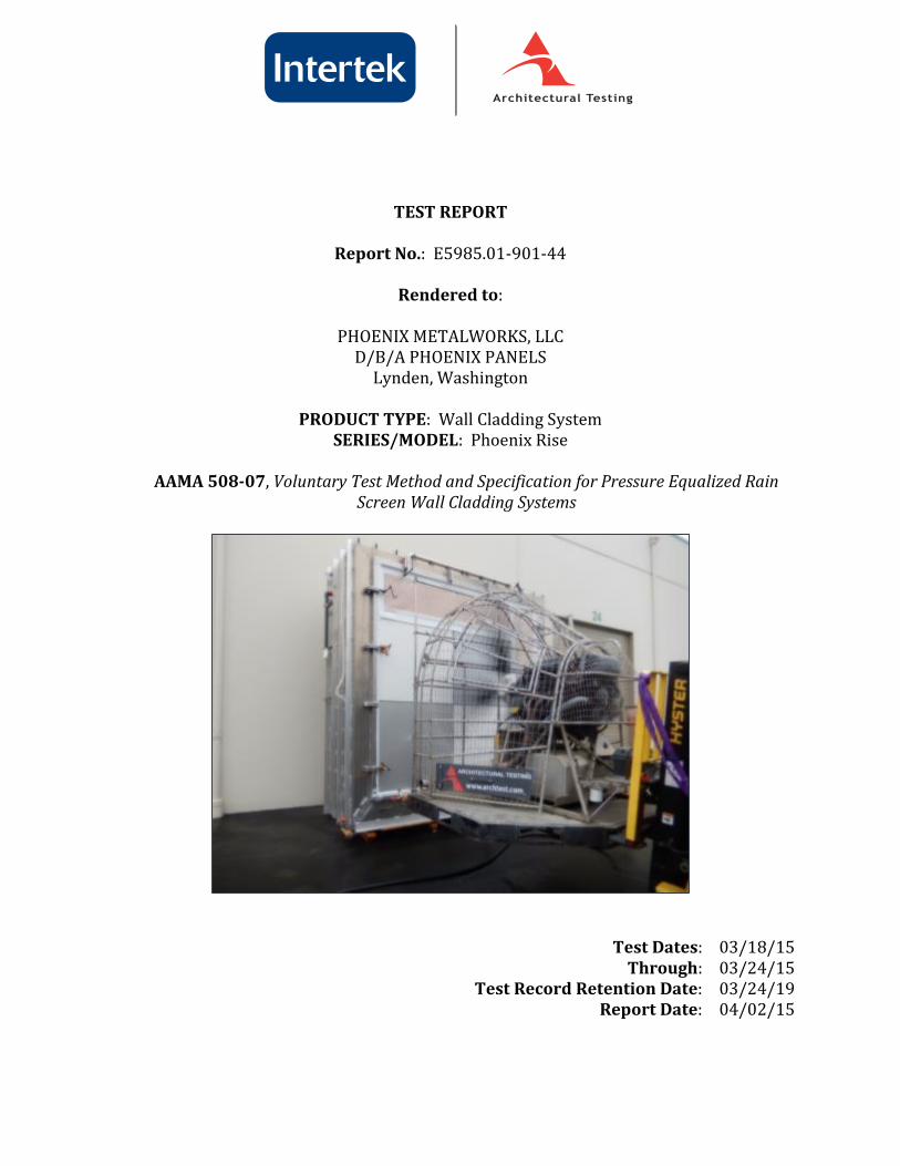
TEST REPORT Report No.: E5985.01-901-44 Rendered to: PHOENIX METALWORKS, LLC D/B/A PHOENIX PANELS Lynden, Washington PRODUCT TYPE: Wall Cladding System SERIES/MODEL: Phoenix Rise AAMA 508-07, Voluntary Test Method and Specification for Pressure Equalized Rain Screen Wall Cladding Systems Test Dates: 03/18/15 Through: 03/24/15 Test Record Retention Date: 03/24/19 Report Date: 04/02/15
Transcript of TEST REPORT Report No. - Phoenix Panels
TEST REPORT
Report No.: E5985.01-901-44
Rendered to:
PHOENIX METALWORKS, LLC D/B/A PHOENIX PANELS
Lynden, Washington
PRODUCT TYPE: Wall Cladding System SERIES/MODEL: Phoenix Rise
AAMA 508-07, Voluntary Test Method and Specification for Pressure Equalized Rain
Screen Wall Cladding Systems
Test Dates: 03/18/15 Through: 03/24/15 Test Record Retention Date: 03/24/19 Report Date: 04/02/15
Test Report No.: E5985.01-901-44 Report Date: 04/02/15
Test Record Retention End Date: 03/24/19 Page 1 of 5
1.0 Report Issued To: Phoenix Metalworks, LLC d/b/a Phoenix Panels 8650 Line Road
Lynden, WA 98264 2.0 Test Laboratory: Architectural Testing, Inc.,
a subsidiary of Intertek (Intertek-ATI) 22155 68th Ave. South Kent, Washington 98032 253-395-5656 3.0 Project Summary:
3.1 Product Type: Wall Cladding System
3.2 Series/Model: Phoenix Rise
3.3 Compliance Statement: Results obtained are tested values and were secured by using the designated test method(s). Test specimen description and results are reported herein.
3.4 Test Dates: 03/18/15 – 03/24/15
3.5 Test Location: Intertek-ATI facility located in Kent, Washington.
3.6 Test Sample Source: The test specimen was provided by the client.
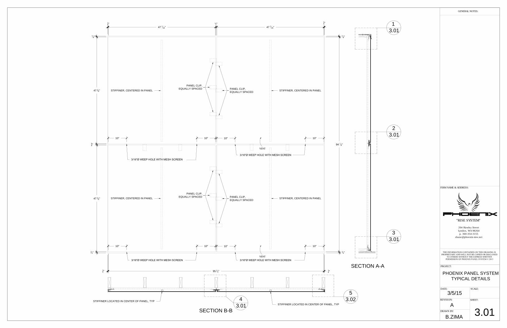
3.7 Drawing Reference: The test specimen drawings have been reviewed by Intertek-ATI and are representative of the test specimen reported herein. Test specimen construction was verified by Intertek-ATI per the drawings located in the appropriate Appendix. Any deviations are documented herein or on the drawings.
3.8 List of Official Observers:
Name Company Brian Rasmussen Intertek-ATI Chris Wilson Intertek-ATI
4.0 Test Method(s):
AAMA 508-07, Voluntary Test Method and Specification for Pressure Equalized Rain Screen Wall Cladding Systems. ASTM E 283-04, Standard Test Method for Determining Rate of Air Leakage Through Exterior Windows, Curtain Walls, and Doors Under Specified Pressure Differences Across the Specimen. Testing was conducted at 75 Pa (1.57 psf) positive static air pressure difference.
www.archtest.com www.intertek.com/building
Test Report No.: E5985.01-901-44 Report Date: 04/02/15
Test Record Retention End Date: 03/24/19 Page 2 of 5
4.0 Test Method(s): (Continued)
ASTM E 1233-06 (Modified), Standard Test Method for Structural Performance of Exterior Windows, Doors, Skylights, and Curtain Walls by Cyclic Static Air Pressure Differential. Testing was conducted for 100, three-second cycles from 240 Pa (5.0 psf) to 1200 Pa (25.0 psf) to 240 Pa (5.0 psf). ASTM E 331-00, Standard Test Method for Water Penetration of Exterior Windows, Skylights, Doors, and Curtain Walls, by Uniform Static Air Pressure Difference. Testing was conducted at 300 Pa (6.24 psf) positive static air pressure difference for a 15-minute duration. Water was applied to the mock-up at a minimum rate of 5 gal/hr/ft2. AAMA 501.1-05, Standard Test Method for Water Penetration of Windows, Curtain Walls, and Doors Using Dynamic Pressure. Testing was conducted with a dynamic pressure equivalent of 300 Pa (6.24 psf) for a 15-minute duration. Water was applied to the mock-up at a minimum rate of 5 gal/hr/ft2.
5.0 Test Specimen Description:
5.1 Product Sizes:
Overall Area: 5.9 m² (64.0 ft2)
Width Height millimeters inches millimeters inches
Overall size 2438 96 2438 96 Panel size (4) 1205 47-7/16 1197 47-1/8
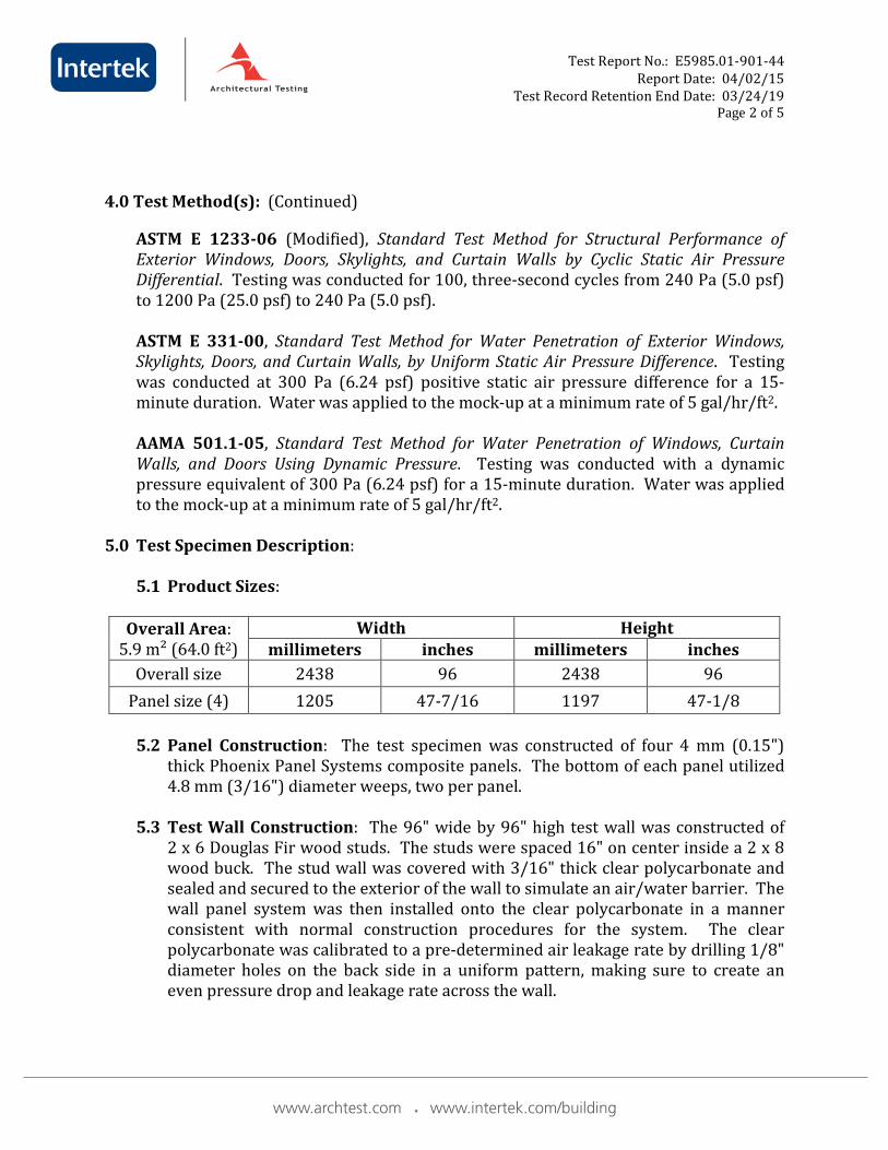
5.2 Panel Construction: The test specimen was constructed of four 4 mm (0.15")
thick Phoenix Panel Systems composite panels. The bottom of each panel utilized 4.8 mm (3/16") diameter weeps, two per panel.
5.3 Test Wall Construction: The 96" wide by 96" high test wall was constructed of
2 x 6 Douglas Fir wood studs. The studs were spaced 16" on center inside a 2 x 8 wood buck. The stud wall was covered with 3/16" thick clear polycarbonate and sealed and secured to the exterior of the wall to simulate an air/water barrier. The wall panel system was then installed onto the clear polycarbonate in a manner consistent with normal construction procedures for the system. The clear polycarbonate was calibrated to a pre-determined air leakage rate by drilling 1/8" diameter holes on the back side in a uniform pattern, making sure to create an even pressure drop and leakage rate across the wall.
www.archtest.com www.intertek.com/building
Test Report No.: E5985.01-901-44 Report Date: 04/02/15
Test Record Retention End Date: 03/24/19 Page 3 of 5
5.0 Test Specimen Description: (Continued)
5.4 Reinforcement: One extruded aluminum tube stiffener, 25 mm x 25 mm (1" x 1"), was adhered to the center of each panel with adhesive sealant.
5.5 Installation: Installation of the tested product was performed by the client.
The panels were installed in a bottom-to-top and left-to-right order. The perimeter of the panel system utilized metal flashing and extruded aluminum clips, secured to the perimeter with #8 x 1-1/4" long screws and spaced approx. 16" on center.
The panels were secured to each stud at the interior horizontal edge with extruded aluminum clips. The clips were secured, one to each stud, with one #8 by 1-1/4" screw. Three extruded aluminum clips were evenly spaced along each panel edge at the vertical joint and secured to the center stud with one #8 by 1-1/4" screw each.
5.6 Cavity Depth: 32 mm (1-1/4")
5.7 Vent Area (Weeps): 0.0001 m2 (0. 22 in2) 5.8 Air Cavity Volume to Vent Area Ratio: 1429.6 m3/m2 (435.8 ft3/ft2)
6.0 Test Results: The temperature during testing was approximately 21°C (70°F). The
results are tabulated as follows:
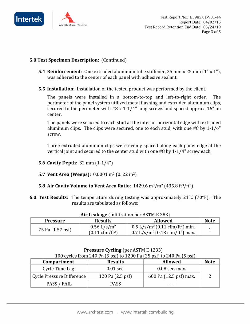
Air Leakage (Infiltration per ASTM E 283) Pressure Results Allowed Note
75 Pa (1.57 psf) 0.56 L/s/m2 (0.11 cfm/ft2)
0.5 L/s/m2 (0.11 cfm/ft2) min. 0.7 L/s/m2 (0.13 cfm/ft2) max. 1
Pressure Cycling (per ASTM E 1233) 100 cycles from 240 Pa (5 psf) to 1200 Pa (25 psf) to 240 Pa (5 psf)
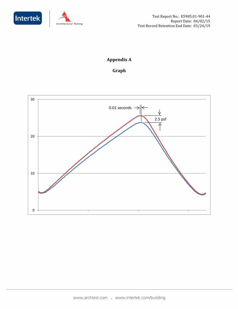
Compartment Results Allowed Note Cycle Time Lag 0.01 sec. 0.08 sec. max.
2 Cycle Pressure Difference 120 Pa (2.5 psf) 600 Pa (12.5 psf) max. PASS / FAIL PASS -----
www.archtest.com www.intertek.com/building
Test Report No.: E5985.01-901-44 Report Date: 04/02/15
Test Record Retention End Date: 03/24/19 Page 4 of 5
6.0 Test Results: (Continued)
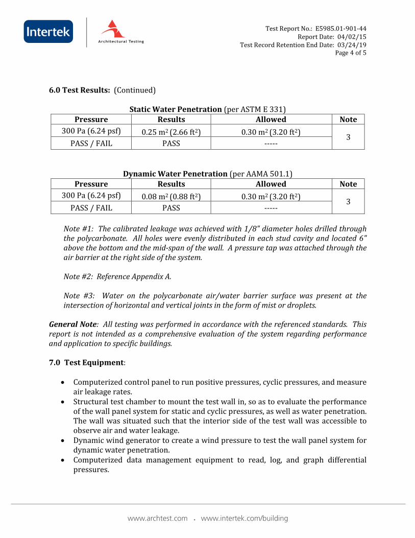
Static Water Penetration (per ASTM E 331) Pressure Results Allowed Note
300 Pa (6.24 psf) 0.25 m2 (2.66 ft2) 0.30 m2 (3.20 ft2) 3 PASS / FAIL PASS -----
Dynamic Water Penetration (per AAMA 501.1) Pressure Results Allowed Note
300 Pa (6.24 psf) 0.08 m2 (0.88 ft2) 0.30 m2 (3.20 ft2) 3 PASS / FAIL PASS -----
Note #1: The calibrated leakage was achieved with 1/8" diameter holes drilled through the polycarbonate. All holes were evenly distributed in each stud cavity and located 6" above the bottom and the mid-span of the wall. A pressure tap was attached through the air barrier at the right side of the system. Note #2: Reference Appendix A. Note #3: Water on the polycarbonate air/water barrier surface was present at the intersection of horizontal and vertical joints in the form of mist or droplets.
General Note: All testing was performed in accordance with the referenced standards. This report is not intended as a comprehensive evaluation of the system regarding performance and application to specific buildings. 7.0 Test Equipment:
• Computerized control panel to run positive pressures, cyclic pressures, and measure air leakage rates.
• Structural test chamber to mount the test wall in, so as to evaluate the performance of the wall panel system for static and cyclic pressures, as well as water penetration. The wall was situated such that the interior side of the test wall was accessible to observe air and water leakage.
• Dynamic wind generator to create a wind pressure to test the wall panel system for dynamic water penetration.
• Computerized data management equipment to read, log, and graph differential pressures.
www.archtest.com www.intertek.com/building
Test Report No.: E5985.01-901-44 Report Date: 04/02/15
Test Record Retention End Date: 03/24/19 Page 5 of 5
The service life of this report will expire on the stated Test Record Retention End Date, at which time such materials as drawings, data sheets, samples of test specimens, copies of this report, and any other pertinent project documentation, shall be discarded without notice. If the test specimen contains glazing, no conclusions of any kind regarding the adequacy or inadequacy of the glass in any glazed test specimen(s) can be made. This report does not constitute certification of this product nor an opinion or endorsement by this laboratory. It is the exclusive property of the client so named herein and relates only to the specimen tested. This report may not be reproduced, except in full, without the written approval of Intertek-ATI For Intertek-ATI: ___________________________________________ ________________________________________________ Brian L. Rasmussen Jeffrey L. Dideon Technician Director – Regional Operations BLR:pac Attachments (pages): This report is complete only when all attachments listed are included. Appendix-A: Graph (1) Appendix-B: Photographs (1) Appendix-C: Drawings (3) This report produced from controlled document template ATI 00521, issued 03/4/11.
www.archtest.com www.intertek.com/building
Test Report No.: E5985.01-901-44 Report Date: 04/02/15
Test Record Retention End Date: 03/24/19
Appendix A
Graph
0
10
20
30
0.01 seconds
2.5 psf
www.archtest.com www.intertek.com/building

Test Report No.: E5985.01-901-44 Report Date: 04/02/15
Test Record Retention End Date: 03/24/19
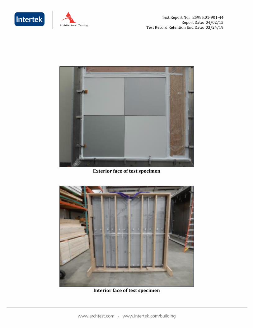
Appendix B
Photographs
www.archtest.com www.intertek.com/building
Test Report No.: E5985.01-901-44 Report Date: 04/02/15
Test Record Retention End Date: 03/24/19
Exterior face of test specimen
Interior face of test specimen
www.archtest.com www.intertek.com/building

Test Report No.: E5985.01-901-44 Report Date: 04/02/15
Test Record Retention End Date: 03/24/19
Appendix C
Drawings
www.archtest.com www.intertek.com/building
PROJECT:
DATE:
REVISION:
SHEET:
FIRM NAME & ADDRESS:
SCALE:
DRAWN BY:
GENERAL NOTES:
204 Hawley Street
Lynden, WA 98264
p. 360-354-3155
THE INFORMATION CONTAINED ON THIS DRAWING ISPROPRIETARY AND WILL NOT BE COPIED OR DISCLOSED
TO OTHERS WITHOUT THE EXPRESS WRITTENPERMISSION OF PHOENIX PANEL SYSTEM © 2013
"RISE SYSTEM"
A
B.ZIMA
3.01
3/5/15
PHOENIX PANEL SYSTEM
TYPICAL DETAILS
SECTION B-B
SECTION A-A
47
7
16
" 47
7
16
"
94
7
8
"
95
1
2
"
1
3.01
2
3.01
3
3.01
5
3.024
3.01
10"
3/16"Ø WEEP HOLE WITH MESH SCREEN
10"
VENT
10"
3/16"Ø WEEP HOLE WITH MESH SCREEN
10"
STIFFINER LOCATED IN CENTER OF PANEL, TYP
STIFFINER LOCATED IN CENTER OF PANEL, TYP
PANEL CLIP,
EQUALLY SPACED
47
1
8
"
47
1
8
"
10"
3/16"Ø WEEP HOLE WITH MESH SCREEN
10"
VENT
10"
3/16"Ø WEEP HOLE WITH MESH SCREEN
10"
5
8
"
5
8"
1
4
"
1
4
"
7
8
"
1
4
"
1
4
"
7
8
"
1
4
"
1
4
"
STIFFINER, CENTERED IN PANEL
STIFFINER, CENTERED IN PANEL
STIFFINER, CENTERED IN PANEL
STIFFINER, CENTERED IN PANEL
PANEL CLIP,
EQUALLY SPACED
PANEL CLIP,
EQUALLY SPACEDPANEL CLIP,
EQUALLY SPACED
brasmussen
New Stamp
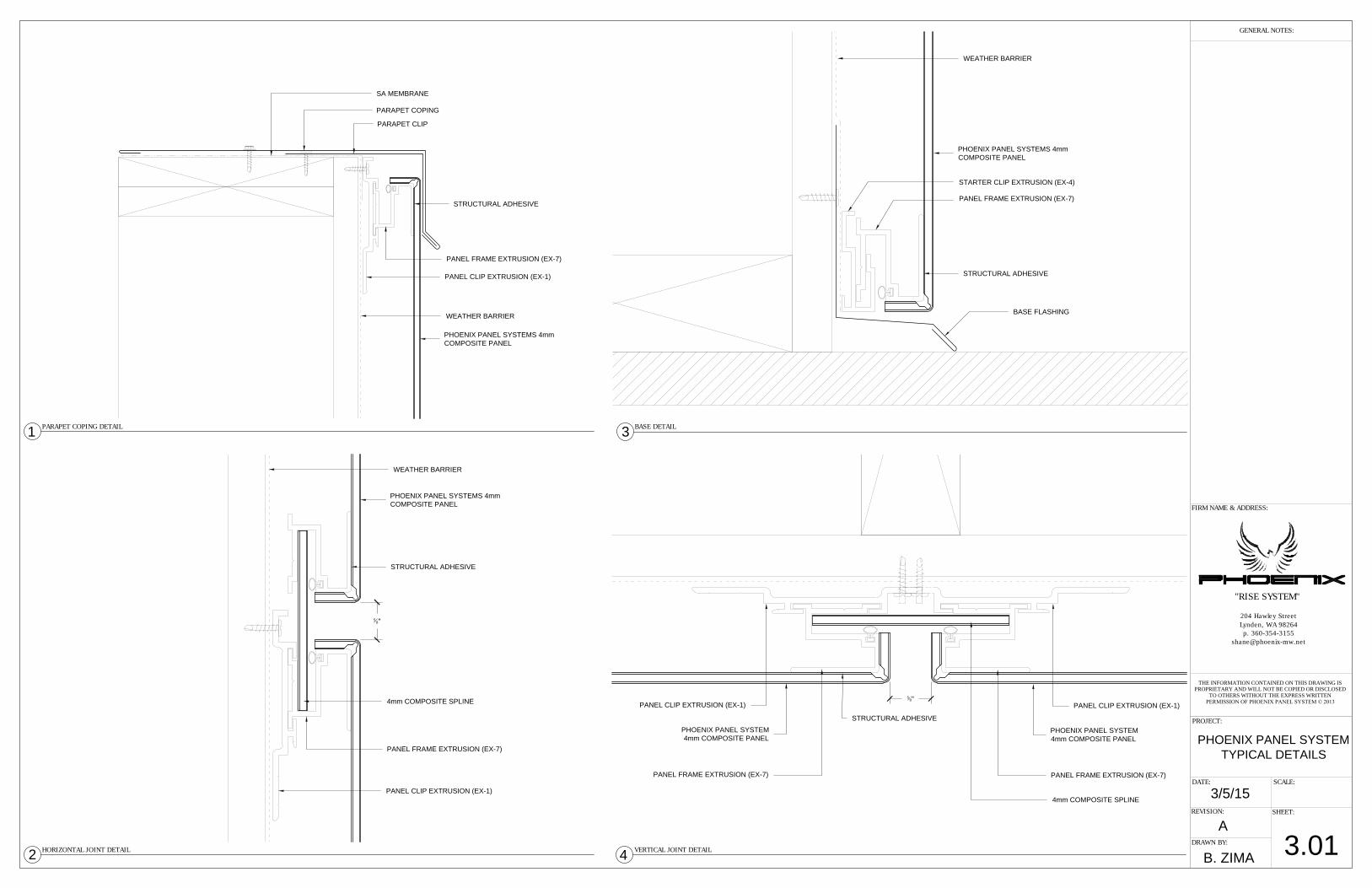
HORIZONTAL JOINT DETAIL
PARAPET COPING DETAIL
1
BASE DETAIL
VERTICAL JOINT DETAIL
PROJECT:
DATE:
REVISION:
SHEET:
FIRM NAME & ADDRESS:
SCALE:
DRAWN BY:
GENERAL NOTES:
204 Hawley Street
Lynden, WA 98264
p. 360-354-3155
THE INFORMATION CONTAINED ON THIS DRAWING ISPROPRIETARY AND WILL NOT BE COPIED OR DISCLOSED
TO OTHERS WITHOUT THE EXPRESS WRITTENPERMISSION OF PHOENIX PANEL SYSTEM © 2013
"RISE SYSTEM"
A
B. ZIMA
3.01
3/5/15
PHOENIX PANEL SYSTEM
TYPICAL DETAILS
2
3
4
PHOENIX PANEL SYSTEMS 4mm
COMPOSITE PANEL
PANEL CLIP EXTRUSION (EX-1)
PANEL FRAME EXTRUSION (EX-7)
PARAPET CLIP
PARAPET COPING
PANEL CLIP EXTRUSION (EX-1)
PANEL FRAME EXTRUSION (EX-7)
PHOENIX PANEL SYSTEMS 4mm
COMPOSITE PANEL
STRUCTURAL ADHESIVE
4mm COMPOSITE SPLINE
STARTER CLIP EXTRUSION (EX-4)
PHOENIX PANEL SYSTEMS 4mm
COMPOSITE PANEL
SA MEMBRANE
WEATHER BARRIER
WEATHER BARRIER
WEATHER BARRIER
PANEL FRAME EXTRUSION (EX-7)
BASE FLASHING
PHOENIX PANEL SYSTEM
4mm COMPOSITE PANEL
PANEL CLIP EXTRUSION (EX-1)
PANEL FRAME EXTRUSION (EX-7)
4mm COMPOSITE SPLINE
PHOENIX PANEL SYSTEM
4mm COMPOSITE PANEL
PANEL CLIP EXTRUSION (EX-1)
PANEL FRAME EXTRUSION (EX-7)
5
8"
5
8"
STRUCTURAL ADHESIVE
STRUCTURAL ADHESIVE
STRUCTURAL ADHESIVE
brasmussen
Line
brasmussen
Line
brasmussen
Line
brasmussen
Text Box
Two separate clips
brasmussen
New Stamp
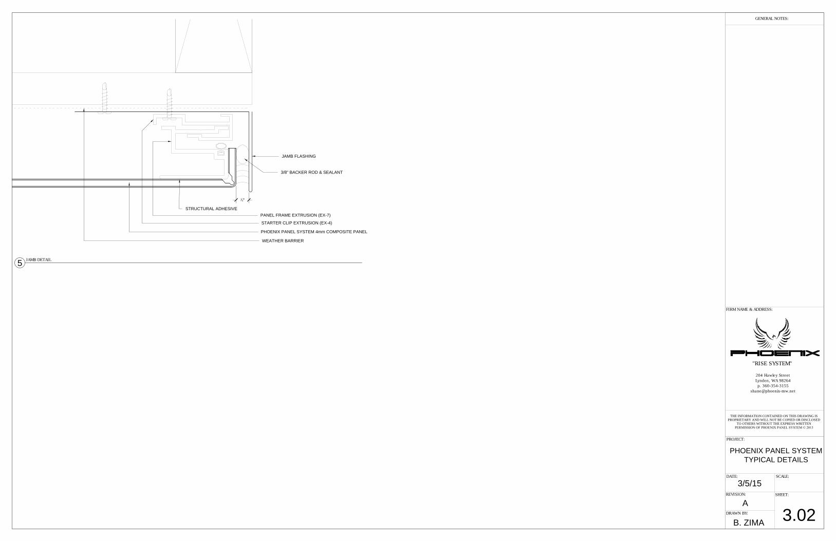
JAMB DETAIL
5
PROJECT:
DATE:
REVISION:
SHEET:
FIRM NAME & ADDRESS:
SCALE:
DRAWN BY:
GENERAL NOTES:
204 Hawley Street
Lynden, WA 98264
p. 360-354-3155
THE INFORMATION CONTAINED ON THIS DRAWING ISPROPRIETARY AND WILL NOT BE COPIED OR DISCLOSED
TO OTHERS WITHOUT THE EXPRESS WRITTENPERMISSION OF PHOENIX PANEL SYSTEM © 2013
"RISE SYSTEM"
A
B. ZIMA
3.02
3/5/15
PHOENIX PANEL SYSTEM
TYPICAL DETAILS
JAMB FLASHING
3/8" BACKER ROD & SEALANT
PANEL FRAME EXTRUSION (EX-7)
STARTER CLIP EXTRUSION (EX-4)
PHOENIX PANEL SYSTEM 4mm COMPOSITE PANEL
WEATHER BARRIER
1
4"
STRUCTURAL ADHESIVE
brasmussen
New Stamp