TEST REPORT No. 319105 - rulourisiobloane.ro
17
Comp. MB Revis. RP This test report is made up of 17 sheets. Sheet 1 of 17 TERMS: This document refers only to the sample or material under test and can not be partially reproduced without written permission of Istituto Giordano. Istituto Giordano S.p.A. Via Rossini, 2 - 47814 Bellaria-Igea Marina (RN) - Italia Tel. +39 0541 343030 - Fax +39 0541 345540 [email protected] - www.giordano.it PEC: ist-[email protected] Cod. Fisc./Part. IVA: 00 549 540 409 - Cap. Soc. € 1.500.000 i.v. R.E.A. c/o C.C.I.A.A. (RN) 156766 Registro Imprese di Rimini n. 00 549 540 409 TEST REPORT No. 319105 Place and date of issue: Bellaria-Igea Marina - Italia, 30/09/2014 Customer: VIOMETALOUMIN BOUTSINIS J. - BAFALOUKAS J. G.P. - Thesi Patima Aspropyrgos - 19300 ATHENS - Greece Date testing request: 11/07/2014 Order number and date: 63738, 14/07/2014 Date sample received: 27/08/2012 Date of testing: from 05/08/2014 to 06/08/2014 Purpose of testing: Burglar resistance and classification (resistance under static load, resistance under dynamic loading and resistance to manual burglary attempts) according to standards UNI EN 1627:2011, UNI EN 1628:2011, UNI EN 1629:2011 and UNI EN 1630:2011 of folding grill Place of testing: Istituto Giordano S.p.A. - Via Erbosa, 72 - 47043 Gatteo (FC) - Italia Origin of sample: sampled and supplied by the Customer Identification of sample received: no. 2014/1574 Name of sample* The sample under test is named “T 120 - 1350×2350”. Description of sample* (*) according to that stated by the Customer. (*) according to the technical documentation supplied by the Customer and on the basis of checks carried out by staff from Istituto Giordano S.p.A..
Transcript of TEST REPORT No. 319105 - rulourisiobloane.ro

Comp. MB
Revis. RP This test report is made up of 17 sheets.
Sheet
1 of 17
TERMS: This document refers only to the sample or material under test and can not be partially reproduced without written permission of Istituto Giordano.
Istituto Giordano S.p.A.
Via Rossini, 2 - 47814 Bellaria-Igea Marina (RN) - Italia
Tel. +39 0541 343030 - Fax +39 0541 345540
[email protected] - www.giordano.it
PEC: [email protected]
Cod. Fisc./Part. IVA: 00 549 540 409 - Cap. Soc. € 1.500.000 i.v.
R.E.A. c/o C.C.I.A.A. (RN) 156766
Registro Imprese di Rimini n. 00 549 540 409
TEST REPORT No. 319105
Place and date of issue: Bellaria-Igea Marina - Italia, 30/09/2014
Customer: VIOMETALOUMIN BOUTSINIS J. - BAFALOUKAS J. G.P. - Thesi Patima Aspropyrgos -
19300 ATHENS - Greece
Date testing request: 11/07/2014
Order number and date: 63738, 14/07/2014
Date sample received: 27/08/2012
Date of testing: from 05/08/2014 to 06/08/2014
Purpose of testing: Burglar resistance and classification (resistance under static load, resistance
under dynamic loading and resistance to manual burglary attempts) according
to standards UNI EN 1627:2011, UNI EN 1628:2011, UNI EN 1629:2011 and UNI
EN 1630:2011 of folding grill
Place of testing: Istituto Giordano S.p.A. - Via Erbosa, 72 - 47043 Gatteo (FC) - Italia
Origin of sample: sampled and supplied by the Customer
Identification of sample received: no. 2014/1574
Name of sample*
The sample under test is named “T 120 - 1350×2350”.
Description of sample*
(*) according to that stated by the Customer.
(*) according to the technical documentation supplied by the Customer and on the basis of checks carried out by staff from Istituto
Giordano S.p.A..

(Rapporto di prova n. 319105 del 30/09/2014) segue - foglio n. 2 di 17
The sample under test consists of a single leaf folding grill, featured as listed in the following table.
Sample total nominal width 1350 mm
Sample total nominal height 2350 mm
Sample usable width 910 mm
Sample usable height 2060 mm
The folding door type 120 consists of columns aluminum reinforced interior with bars of iron. The columns
linked together with inox 316 shears. The door pulled into the upper and lower guide with bearings that are
at the bottom of the door. The profile lock has a security lock to which may be locked either in or out as also
being locked only from the inside without being seen from the outside of the lock. The folding door can only
be pulled or rotate. When the door rotates four profiles of the hinge is designed in such a way as to achieve
the 180° rotation of the door while providing protection. The folding door movement to the one side (single
leaf door).
Further details of sample specifications can be seen in the Customer-supplied list of components and sche-
matic drawings set out hereafter.
Finally, the sample has a surrounding steel frame used to hold the test installation securely in place.
Customer-supplied list of components.
Code Description Quantity
17.22 apostate 1
17.23 locking blade 2
17.24 folding shear 80
17.25 support plate 2
17.26 clamp restraint 1
17.27 plastic to centre the lock 1
17.28 plastic rotary joint 2
17.29 hinge A profile 1
17.30 hinge B profile 1
17.31 reinforced beam profile 9
17.32 reinforced beam hng profile 1
17.33 frame hinge profile 1
17.34 reinforced beam lock profile 1
(Rapporto di prova n. 319105 del 30/09/2014) segue - foglio n. 3 di 17
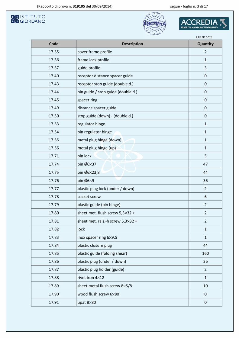
Code Description Quantity
17.35 cover frame profile 2
17.36 frame lock profile 1
17.37 guide profile 3
17.40 receptor distance spacer guide 0
17.43 receptor stop guide (double d.) 0
17.44 pin guide / stop guide (double d.) 0
17.45 spacer ring 0
17.49 distance spacer guide 0
17.50 stop guide (down) - (double d.) 0
17.53 regulator hinge 1
17.54 pin regulator hinge 1
17.55 metal plug hinge (down) 1
17.56 metal plug hinge (up) 1
17.71 pin lock 5
17.74 pin Ø6×37 47
17.75 pin Ø6×23,8 44
17.76 pin Ø6×9 36
17.77 plastic plug lock (under / down) 2
17.78 socket screw 6
17.79 plastic guide (pin hinge) 2
17.80 sheet met. flush screw 5,3×32 + 2
17.81 sheet met. rais.-h screw 5,3×32 + 2
17.82 lock 1
17.83 inox spacer ring 6×9,5 1
17.84 plastic closure plug 44
17.85 plastic guide (folding shear) 160
17.86 plastic plug (under / down) 36
17.87 plastic plug holder (guide) 2
17.88 rivet iron 4×12 1
17.89 sheet metal flush screw 8×5/8 10
17.90 wood flush screw 6×80 0
17.91 upat 8×80 0

(Rapporto di prova n. 319105 del 30/09/2014) segue - foglio n. 4 di 17
Code Description Quantity
17.92 rivet al 5×16 3
17.93 rivet 5×8 2
17.94 bearing 3
17.95 washer aluminium 3
17.96 metal screw 5,3×20 20
SAMPLE ELEVATIONS

(Rapporto di prova n. 319105 del 30/09/2014) segue - foglio n. 5 di 17
HORIZONTAL SECTION

(Rapporto di prova n. 319105 del 30/09/2014) segue - foglio n. 6 di 17
VERTICAL SECTION

(Rapporto di prova n. 319105 del 30/09/2014) segue - foglio n. 7 di 17
COMPONENTS
9 10 9
34
1,5
6
1,7
2
11
15
17.22
17.23
61
32
8
6
R3
Ø7
52
14
24
8
17.24
21
66
16
R8
Ø9
Ø6,1
5
81
00
10
08
17.25
3
20
3
20
45
0
47
0
17.26
3
20
27
0
Ø5
34
61
0
9
R5
R10
22
61
0
17.27
52 6
2,5 28
R6
10
7
33
41
5
75
30
20
1
2
53
R22
66
46
2,51,5
4
54
18
10
22
50
3
17.28
39
,8
53
2
2
14,5
22
77,3
53
4,3
R10,5R12,5 4,2
2
17.29
2,52
15
24
22
R3
Ø10,3
66
13
1,4
17.30

(Rapporto di prova n. 319105 del 30/09/2014) segue - foglio n. 8 di 17
PROFILES
60°
10
,7
14
,6
30,62
16,3
6,44,35
1,2
13
,6
34,6
2,88
1,2
17.31
6,4
1,2
11,651,2
16,3 11,651,2
3,7 3,7
2
25
1,85 3,5
6,5
16
17
29
45
,5
1,2
R3,7
R2,5R5
21
1,8
22
35
,8
14
,6
4,8
1,8
17.32
17.33
6,5
17
4,8
43
,5
26
,5
1,451,4
7,832,41,8
42
2,5
15
,2
33
,8
2,3
1,1
21
24,2 2,3
1,1
5,5
2,5
15
,2
30
16,3
6,5
6,6
6,5
1,8
1,2
1,8
9,3
2
12,07 16,329,15
42
8,5
2
1,5
5
8
20,5
31,2
30
,1
15
R3,7
R2,7
R3,7
3
1,7
21,3
2642
71
1 15
,51
3,3
38
28
,8
70
22
45
3 2
1,2
4
1,2
3
17.34
23,6
22,1320,718,7
1,6
91
,45
17.35
17.36
59°
7,2
14
,6
6,4
5,4
7,86,6
Ø7
,4
R3,7
R2,5
19
,6
16,3
18,7
2527,434,6
42
7,2
24,221
3843,5
46,5
39
,2
61
,64
9,6
1,5 1,5
R6,23
R 4,75
5,3
1,11
,2
17.37
48
51,6
20,2 11,2 20,22 2
15,2
18,8
1,5 2
,2 1,8
40
,2
1,8
R2,5R3,5
Normative references
The test was performed according to the requirements of the following standards:
– UNI EN 1627:2011 dated 16/06/2011 “Porte pedonali, finestre, facciate continue, inferriate e chiusure
oscillanti - Resistenza all’effrazione - Requisiti e classificazione” (Pedestrian doorsets, windows, curtain wall-
ing, grilles and shutters - Burglar resistance - Requirements and classification);
– UNI EN 1628:2011 dated 16/06/2011 “Porte pedonali, finestre, facciate continue, inferriate e chiusure
oscuranti - Resistenza all’effrazione - Metodo di prova per la determinazione della resistenza sotto carico
statico” (Pedestrian doorsets, windows, curtain walling, grilles and shutters - Burglar resistance - Test method for
the determination of resistance under static loading);
– UNI EN 1629:2011 dated 16/06/2011 “Porte pedonali, finestre, facciate continue, inferriate e chiusure
oscuranti - Resistenza all’effrazione - Metodo di prova per la determinazione della resistenza sotto carico

(Rapporto di prova n. 319105 del 30/09/2014) segue - foglio n. 9 di 17
dinamico” (Pedestrian doorsets, windows, curtain walling, grilles and shutters - Burglar resistance - Test method
for the determination of resistance under dynamic loading);
– UNI EN 1630:2011 dated 16/06/2011 “Porte pedonali, finestre, facciate continue, inferriate e chiusure
oscuranti - Resistenza all’effrazione - Metodo di prova per la determinazione della resistenza all’azione
manuale di effrazione” (Pedestrian doorsets, windows, curtain walling, grilles and shutters - Burglar resistance -
Test method for the determination of resistance to manual burglary attempts).
Test method
The test was performed according to the requirements of the standards mentioned under the heading
“Normative References” using detailed internal procedure PP009 review 12 dated 16/11/2011 “Porte, porte
pedonali, finestre, facciate continue, inferriate e chiusure oscillanti - Resistenza all’effrazione: Metodi di
prova e classificazione” (Doors, pedestrian doorsets, windows, curtain walling, grilles and shutters - Burglar re-
sistance: Test methods and classification).
Check and comparison of documentation provided and sample to be tested
In accordance with the requirements of standards UNI EN 1627:2011, UNI EN 1628:2011, UNI EN
1629:2011 and UNI EN 1630:2011 was checked the following documentation:
– description of the sample (type of product, characteristics of profiles, materials used and the thick-
ness of the infill or glazing);
– mechanical properties of the materials;
– date of manufacture of the sample;
– declaration about classification of glazing;
– declaration about classification of the hardware;
– side of attack;
– drawings including tolerances and part list;
– installation instructions.
Static load in accordance with standard UNI EN 1628:2011
The test sample was subjected to a series of static loads for the resistance class 2.

(Rapporto di prova n. 319105 del 30/09/2014) segue - foglio n. 10 di 17
The loads were applied through a pressing device, connected to a pneumatic piston, diameter 250 mm,
controlled by motorized reducing valve able to apply the load with a predetermined gradient. The loads
were detected by the use of a load cell, scale 25 000 N.
The deformation have been verified through a series of pass/fail templates conforming to paragraph A.10
of standard UNI EN 1628:2011.
The equipment used complies with the requirements of clause 4.8 “Tollerances” of standard UNI EN
1628:2011, therefore compliance with the class is set without regard to the banks by the uncertainty on
the value of deformation, in line with paragraph 2.6 help ILAC G8: 03/2009 “Guidelines on the Reporting
of Compliance with Specification”.
Dynamic load in accordance with standard UNI EN 1629:2011
The test sample was subjected to a series of impacts to the resistance class 2 with element of impact of
mass 50 kg according to the figure A.29 - Movable grilles: Impact points of standard UNI EN 1629:2011.
Manual burglar test in accordance with standard UNI EN 1630:2011
The test sample was subjected to a series of preliminary tests for resistance class 2 on the following areas:
– vertical bar;
– cross bar;
– rebate area, vertically, between sash and frame lock side;
– rebate area, vertically, back side between grill and frame.
For the preliminary tests were used set of tools “A1” and “A2”.
Afterwards the sample was subjected to the final test for resistance class 2 with attack to the vertically
bar, using the set of tools “A1” and “A2” used during the preliminary tests.
Test apparatus
The tests were carried out using the following equipment:
– burglar resistance test rig (in-house identification code: EDI048) with a loading device (internal equip-
ment identification code: FT481) connected to a load cell of 25 kN with calibration report issued by Isti-
tuto Giordano S.p.A.;

(Rapporto di prova n. 319105 del 30/09/2014) segue - foglio n. 11 di 17
– series of load devices (in-house identification codes: EDI074a, EDI074b, EDI074c, EDI074d, EDI074e,
EDI074f and EDI074g);
– series of calibrated templates (in-house identification codes: EDI075a, EDI075b, EDI075c and EDI075d);
– series of calibrated templates (in-house identification codes: EDI079a, EDI079b and EDI079c);
– mechanical device for the application of dynamic loads consisting of a special lifting system for adjusting
the height completely electromechanical and mechanical system of the position of lateral translation and
by impact element (in-house identification code: EDI012);
– metric bar (in-house identification code: FT364);
– digital caliper (in-house identification code: EDI066);
– stopwatch (in-house identification code: FT462);
– thermo-hygrometer (in-house identification code: FT231);
– digital video-camera;
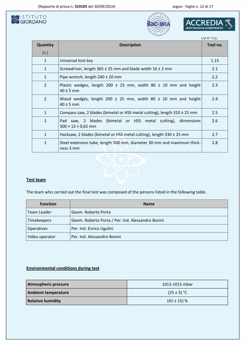
– tools for manual attack test (in-house identification code: FT341), defined on the basis of expected class
and shown in the table in the following sheets.
Quantity Description Tool no.
[n.]
1 Multiple slip joint gripping pliers, maximum length 250 ± 10 mm 1.1
1 Screwdriver, total length 260 ± 20 mm, shaft diameter of 8 ± 2 mm and
blade width 10 ± 1) mm
1.2
1 Set of small screwdrivers with different blade forms, shaft diameter maxi-
mum 6 ± 2 mm and total maximum length 250 mm
1.3
// Hexagonal allen keys, maximum length 120 mm 1.4
// Spanners, maximum length 180 mm 1.5
1 Engineer pliers, maximum length 200 mm 1.6
1 Tweezer 1.7
1 Knife, maximum length of blade 120 mm, thickness of blade maximum
3 mm
1.8
1 Torch 1.9
Hooks 1.10
// Steel wire 1.11
// Adhesive tape 1.12
// String 1.13
1 Rubber hammer, shore hardness 90 ± 10 shore, head weight 100 ± 20g, to-
tal weight 145 ± 20 g and length 260 ± 20 mm
1.14
(Rapporto di prova n. 319105 del 30/09/2014) segue - foglio n. 12 di 17
Quantity Description Tool no.
[n.]
1 Universal lock key 1.15
1 Screwdriver, length 365 ± 25 mm and blade width 16 ± 2 mm 2.1
1 Pipe wrench, length 240 ± 20 mm 2.2
2 Plastic wedges, length 200 ± 25 mm, width 80 ± 10 mm and height
40 ± 5 mm
2.3
2 Wood wedges, length 200 ± 25 mm, width 80 ± 10 mm and height
40 ± 5 mm
2.4
1 Compass saw, 2 blades (bimetal or HSS metal cutting), length 310 ± 25 mm 2.5
1 Pad saw, 2 blades (bimetal or HSS metal cutting), dimensions
300 × 13 × 0,65 mm
2.6
1 Hacksaw, 2 blades (bimetal or HSS metal cutting), length 330 ± 25 mm 2.7
1 Steel extension tube, length 500 mm, diameter 30 mm and maximum thick-
ness 3 mm
2.8
Test team
The team who carried out the final test was composed of the persons listed in the following table.
Function Name
Team Leader Geom. Roberto Porta
Timekeepers Geom. Roberto Porta / Per. Ind. Alessandro Bonini
Operatives Per. Ind. Enrico Ugulini
Video operator Per. Ind. Alessandro Bonini
Environmental conditions during test
Atmospheric pressure 1013-1015 mbar
Ambient temperature (25 ± 3) °C
Relative humidity (45 ± 15) %

(Rapporto di prova n. 319105 del 30/09/2014) segue - foglio n. 13 di 17
Test results
Checking of the documentation supplied and of the test sample
The results of the verifications of the documentation and sample, closed and locked in the closed condi-
tion, is shown in the following table.
Document to provide Reference provided Result
Sample description document named “DESCRIPTION OF THE
SAMPLE Τ120.doc”
compliant
Material properties document named DESCRIPTION OF THE
SAMPLE Τ120.doc” and “ADDITIONAL IN-
FORMATION OF MECHANICAL PARTS -
SAMPLE T120”
compliant
Date of production provided compliant
Glazing class not supplied not suitable
Hardware classification for multipoint lock “ADDITIONAL INFOR-
MATION OF MECHANICAL PARTS - SAMPLE
T120”
compliant
for the cylinder (EN 1303) compliant*
for cylinder protection (EN 1906) compliant*
Side of the attack shown on the sample and in the technical
documentation
compliant
Construction drawings with
dimensional tolerances
Drawings named “DETAILED PLANS LISTED
T120.pdf”
compliant
Installation instructions Documents named “THE MANUFACTUR-
ER'S INSTRUCTIONS FOR INSTALLATION
Τ120.doc”
compliant
(*) not reachable from outside.

(Rapporto di prova n. 319105 del 30/09/2014) segue - foglio n. 14 di 17
Static load in accordance with standard UNI EN 1628:2011.
RC 2 product classifiable in group 4
Loading point Load device Load Used template Result
[kN]
F1 5 3 D compliant
F1.1 5 3 D compliant
F2.1 5 1,5 D compliant
F2.2 5 1,5 D compliant
F2.3 1 1,5 D compliant
F3A
2 3 D
compliant
F3B compliant
F3C compliant
F3D compliant
F3E compliant

(Rapporto di prova n. 319105 del 30/09/2014) segue - foglio n. 15 di 17
LAYOUT OF LOADING POINTS
DURING STATIC LOAD TEST
F3A
F3B
F3C
F3D
F3E
F1.1
F1
F2.1
F2.2
F2.3

(Rapporto di prova n. 319105 del 30/09/2014) segue - foglio n. 16 di 17
Dynamic loading in accordance with standard UNI ENV 1629:2011
RC 2
Result of test the sample remains closed with evident deformations
Manual burglary test (attack from outside) in accordance with standard UNI ENV 1630:2011
Preliminary tests - RC 2
Test zone Operative time Used tools Attack description
[min:s]
vertical bar 3:00 2.1, 2.2, 2.4 The operator using a couple of screwdrivers and a
rubber hammer deforms and uncouple the connec-
tion between cross bars and vertical bars. At the
end of the working time 3 connection are fully re-
moved while 1 is very damaged but is still connect-
ed.
cross bar 3:00 2.1, 2.2, 2.4 The operator assaults the cross bar with the saw. In
the working time he managed to cut 3 bars and
remove only one and half cross connection. To
open the grill is necessary to remove a minimum of
4 connections
rebate area, ver-
tically, between
sash and frame
lock side
3:00 2.1, 2.2, 2.4 The operator using a couple of screwdriver and the
rubber hammer attend to put the screwdriver be-
tween the fixed frame and the moveable parts of
the grill. The particular conformation o of the con-
nection does not allow this operation with class 2
tools
rebate area, ver-
tically, back side
between grill and
frame
3:00 2.1, 2.2, 2.4 The operator using a couple of screwdriver and the
rubber hammer attend to put the screwdriver be-
tween the fixed frame and the first fixed vertical
bar of the grill. The particular conformation of the
connection does not allow this operation with class
2 tools

(Rapporto di prova n. 319105 del 30/09/2014) segue - foglio n. 17 di 17
Main test- RC 2
Test zone Operative
time
Gross time Used tools Attack description
[min:s] [min:s]
rebate area, ver-
tically, between
sash and frame
lock side
3:00 6:20 2.1, 2.2,
2.4
The operator using a big screwdriver, the little
screwdriver and a rubber hammer deforms
and disengages the connection between cross
bars and vertical bars. At the end of the work-
ing time are 3 connection fully removed while
one is still connected but very damaged
Classification.
On the basis of the test performed, the results obtained and the provisions of standards UNI EN 1627:2011,
UNI EN 1628:2011, UNI EN 1629:2011 and UNI EN 1630:2011, the test sample, comprising a single-leaf door,
called “T 120 - 1350×2350” and submitted by the company VIOMETALOUMIN BOUTSINIS J. - BAFALOUKAS J.
G.P. - Thesi Patima Aspropyrgos - 19300 ATHENS - Greece, has passed the tests prescribed therein.
Therefore, in accordance with standard UNI EN 1627:2011, the sample belong to
RC 2*
The results given refer exclusively to the test sample itself and are only valid under the same conditions in
which testing was carried out.
This test report alone shall not be considered a certificate of conformity.
(*) The classification was determined based on the measured values obtained experimentally, in line with paragraph 2.6 of the guide
ILAC G8: 03/2009 “Guidelines on the reporting of compliance with specification”.
Test Technician
(Geom. Roberto Porta)
Head of
Security and Safety Laboratory
(Dott. Andrea Bruschi)
Chief Executive Officer
(Dott. Arch. Sara Lorenza Giordano)
............................................
............................................
............................................