Test Report - Glenair Report Stacker Qualification GT-17-221 Revision A 10/27/17 ... Figure 1:...
56
Test Report Stacker Qualification GT-17-221 Revision A 10/27/17 Glenair, Inc. 1211 Air Way ∙ Glendale, California 91201-2497 Telephone: 818-247-6000 ∙ Facsimile: 818-500-9912 E-mail: [email protected] United States ∙ United Kingdom ∙ Germany ∙ France ∙ Nordic ∙ Italy www.glenair.com
Transcript of Test Report - Glenair Report Stacker Qualification GT-17-221 Revision A 10/27/17 ... Figure 1:...

Test Report Stacker Qualification
GT-17-221 Revision A
10/27/17
Glenair, Inc. 1211 Air Way ∙ Glendale, California 91201-2497
Telephone: 818-247-6000 ∙ Facsimile: 818-500-9912 E-mail: [email protected]
Uni ted S ta tes ∙ Un i ted K ingdom ∙ Germany ∙ France ∙ Nord ic ∙ I ta ly
www.glenair.com

TEST REPORT
Cage Code:
06324 Stacker Qualification
Document #: GT-17-221
Revision: 1
Page 1 of 55
This copyrighted document is the property of Glenair Inc. and is furnished on the condition that it will not be disclosed, reproduced in part
or whole or used to solicit quotations from competitive sources without the written permission of Glenair, Inc.
List of Tables
Table 1: Report Revision History ............................................................................................................................................. 3
Table 2: Test Deviations.......................................................................................................... Error! Bookmark not defined.
Table 3: Test Sample Identification ......................................................................................................................................... 6
Table 4: Test Groups and Order of Testing .............................................................................................................................. 7
Table 5: Visual Inspection Test Equipment ............................................................................................................................. 8
Table 6: Contact Engagement and Separation Forces Testing Equipment ............................................................................. 10
Table 7: .022” (+) Gauge Pin Results in lb ............................................................................................................................ 11
Table 8: .023” (-) Gauge Pin Results in lb ............................................................................................................................. 11
Table 9: .020” (+) Gauge Pin Results in lb ............................................................................................................................ 11
Table 10: Contact Retention Testing Equipment ................................................................................................................... 13
Table 11: Contact Retention Testing Results ......................................................................................................................... 13
Table 12: DWV at Altitude Test Equipment .......................................................................................................................... 15
Table 13: Contact Compliant Mating Forces Test Equipment ............................................................................................... 17
Table 14: Contact Compliance Mating Forces Results .......................................................................................................... 17
Table 15: Contact Life Test Equipment ................................................................................................................................. 20
Table 16: Mating and Unmating Force Test Equipment ........................................................................................................ 22
Table 17: Pre Vibration and Shock Mating and Unmating Force Results .............................................................................. 22
Table 18: Low Level Contact Resistance Test Equipment ..................................................................................................... 24
Table 19: Pre Vibration and Shock Low Level Contact Resistance Results .......................................................................... 24
Table 20: Vibration Test Equipment ...................................................................................................................................... 26
Table 21: Mechanical Shock Test Equipment ....................................................................................................................... 29
Table 22: Low Level Contact Resistance Test Equipment ..................................................................................................... 32
Table 23: Post Vibration and Shock Low Level Contact Resistance Results ......................................................................... 32
Table 24: Mating and Unmating Force Test Equipment ........................................................................................................ 33
Table 25: Post Vibration and Shock Mating and Unmating Force ......................................................................................... 33
Table 26: Contact Compliant Forces Test Equipment ............................................................................................................ 35
Table 27: Contact Compliance Mating Forces Results .......................................................................................................... 35
Table 28: DWV at Sea Level Test Equipment ....................................................................................................................... 37
Table 29: Insulation Resistance Test Equipment.................................................................................................................... 39
Table 30: Temperature Cycling Test Equipment ................................................................................................................... 40
Table 31: Contact Resistance Testing Equipment .................................................................................................................. 42
Table 32: Post Thermal Shock Contact Resistance Results ................................................................................................... 42
Table 33: Humidity Exposure Testing Equipment ................................................................................................................. 44
Table 34: Insulation Resistance Test Equipment.................................................................................................................... 47
Table 35: Contact Resistance Test Equipment ....................................................................................................................... 48
Table 36: Post Humidity Exposure Contact Resistance Results............................................................................................. 48
Table 37: Low Level Contact Resistance Test Equipment ..................................................................................................... 49
Table 38: Low Level Contact Resistance Results .................................................................................................................. 49
Table 39: Post Humidity Mating and Unmating Force Results .............................................................................................. 50
Table 40: Post Humidity Mating and Unmating Force Results .............................................................................................. 50
Table 41: Contact Compliant Removal Forces Test Equipment ............................................................................................ 52
Table 42: Contact Compliant Removal Forces Results .......................................................................................................... 52

TEST REPORT
Cage Code:
06324 Stacker Qualification
Document #: GT-17-221
Revision: 1
Page 2 of 55
This copyrighted document is the property of Glenair Inc. and is furnished on the condition that it will not be disclosed, reproduced in part
or whole or used to solicit quotations from competitive sources without the written permission of Glenair, Inc.
List of Figures
Figure 1: Drawing of Test Sample ........................................................................................................................................... 5
Figure 2: Stacker Mated Pair from Group 1 ............................................................................................................................. 6
Figure 3: Example of Initial Picture of Sample 1A at 10x Magnification ................................................................................ 9
Figure 4: Example of Initial Picture of Sample 2A at 10x Magnification ................................................................................ 9
Figure 5: Example of Contact Engagement and Separation Test Setup ................................................................................. 12
Figure 6: Example of Contact Retention Test Setup .............................................................................................................. 14
Figure 7: Stacker Sample Ready for DWV at Altitude in Chamber. ..................................................................................... 16
Figure 8: PCB Mating Force for Samples 1A and 2A ............................................................................................................ 18
Figure 9: Samples shown with PCB boards installed ............................................................................................................. 19
Figure 10: Contact Life Testing Setup ................................................................................................................................... 21
Figure 11: Sample 2A-1A Mating and Unmating Force Pre Vibration and Shock ................................................................ 23
Figure 12: Stacker Connector Sample during Low Level Resistance Testing ....................................................................... 25
Figure 13: Vibration Profile ................................................................................................................................................... 27
Figure 14: Vibration Shaker and Discontinuity Tester Setup ................................................................................................. 28
Figure 15: Close up of Stacker Vibration Fixture .................................................................................................................. 28
Figure 16: Terminal Sawtooth Shock in Positive Direction ................................................................................................... 30
Figure 17: Terminal Sawtooth Shock in Negative Direction ................................................................................................. 30
Figure 18: Sample 2A-1A Mating and Unmating Force Post Vibration and Shock ............................................................... 34
Figure 19: Contact Compliant Mating Forces of Sample 1B and 2B ..................................................................................... 36
Figure 20: Stacker Test Sample Attached to Adapter for DWV Testing ............................................................................... 38
Figure 21: Thermal Shock Temperature Profile .................................................................................................................... 40
Figure 22: Samples Read for Thermal Shock Testing ........................................................................................................... 41
Figure 23: A Single Cycle of Humidity Exposure Testing ..................................................................................................... 45
Figure 24: Samples 2A and 2B ready for Humidity Exposure Testing ................................................................................. 46
Figure 25: Small Amount of Discoloration Visible on Sample Contacts ............................................................................... 46
Figure 26: Sample 2B-1B Post Humidity Mating and Unmating Force Trace ....................................................................... 51
Figure 27: PCB Dismounting Force for Sample 2B ............................................................................................................... 53
Figure 28: PCB Dismounting Fixture ..................................................................................................................................... 54
Figure 29: Dismount Complete .............................................................................................................................................. 54
TEST REPORT
Cage Code:
06324 Stacker Qualification
Document #: GT-17-221
Revision: 1
Page 3 of 55
This copyrighted document is the property of Glenair Inc. and is furnished on the condition that it will not be disclosed, reproduced in part
or whole or used to solicit quotations from competitive sources without the written permission of Glenair, Inc.
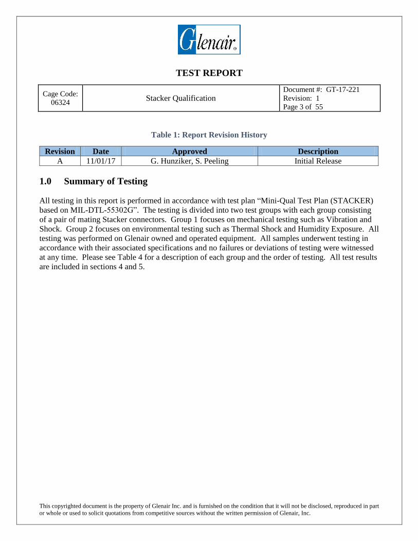
Table 1: Report Revision History
Revision Date Approved Description
A 11/01/17 G. Hunziker, S. Peeling Initial Release
1.0 Summary of Testing
All testing in this report is performed in accordance with test plan “Mini-Qual Test Plan (STACKER)
based on MIL-DTL-55302G”. The testing is divided into two test groups with each group consisting
of a pair of mating Stacker connectors. Group 1 focuses on mechanical testing such as Vibration and
Shock. Group 2 focuses on environmental testing such as Thermal Shock and Humidity Exposure. All
testing was performed on Glenair owned and operated equipment. All samples underwent testing in
accordance with their associated specifications and no failures or deviations of testing were witnessed
at any time. Please see Table 4 for a description of each group and the order of testing. All test results
are included in sections 4 and 5.

TEST REPORT
Cage Code:
06324 Stacker Qualification
Document #: GT-17-221
Revision: 1
Page 4 of 55
This copyrighted document is the property of Glenair Inc. and is furnished on the condition that it will not be disclosed, reproduced in part
or whole or used to solicit quotations from competitive sources without the written permission of Glenair, Inc.
2.0 General Information
2.1 References
Mini-Qual Test Plan (STACKER) based on MIL-DTL-55302G
MIL-DTL-55302G – Connectors, Printed Circuit Subassembly and Accessories
EIA-364-37 – Contact Engagement and Separation Test Procedure for Electrical
Connectors
EIA-364-29 – Contact Retention Test Procedure for Electrical Connectors
EIA-364-20 – Withstanding Voltage Test Procedure for Electrical Connectors, Sockets and
Coaxial Contacts
EIA-364-23 – Low Level Contact Resistance Test Procedure for Electrical Connectors and
Sockets
EIA-364-28 – Vibration Test Procedure for Electrical Connectors and Sockets
EIA-364-27 – Mechanical Shock (Specified Pulse) Test Procedure for Electrical
Connectors and Sockets
EIA-364-21 – Insulation Resistance Test Procedure for Electrical Connectors, Sockets and
Coaxial Contacts
EIA-364-32 – Thermal Shock (Temperature Cycling) Test Procedure for Electrical
Connectors and Sockets
EIA-364-06 – Contact Resistance Test Procedure for Electrical Connectors
EIA-364-31 – Humidity Test Procedure for Electrical Connectors and Sockets
TEST REPORT
Cage Code:
06324 Stacker Qualification
Document #: GT-17-221
Revision: 1
Page 5 of 55
This copyrighted document is the property of Glenair Inc. and is furnished on the condition that it will not be disclosed, reproduced in part
or whole or used to solicit quotations from competitive sources without the written permission of Glenair, Inc.
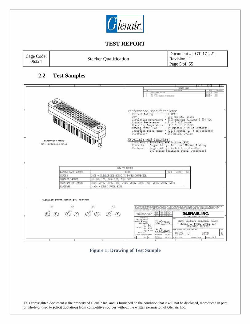
2.2 Test Samples
Figure 1: Drawing of Test Sample

TEST REPORT
Cage Code:
06324 Stacker Qualification
Document #: GT-17-221
Revision: 1
Page 6 of 55
This copyrighted document is the property of Glenair Inc. and is furnished on the condition that it will not be disclosed, reproduced in part
or whole or used to solicit quotations from competitive sources without the written permission of Glenair, Inc.
Figure 2: Stacker Mated Pair from Group 1
Table 2: Test Sample Identification
Group Number Sample Part Number Description Sample Label
1 GSTB-120-.270-G1 120 Pin “Stacker” Connector 1A
1 GSTB-120-.270-G1 120 Pin “Stacker” Connector 2A
2 GSTB-120-.270-G1 120 Pin “Stacker” Connector 1B
2 GSTB-120-.270-G1 120 Pin “Stacker” Connector 2B

TEST REPORT
Cage Code:
06324 Stacker Qualification
Document #: GT-17-221
Revision: 1
Page 7 of 55
This copyrighted document is the property of Glenair Inc. and is furnished on the condition that it will not be disclosed, reproduced in part
or whole or used to solicit quotations from competitive sources without the written permission of Glenair, Inc.
3.0 Test Sequence
Table 3: Test Groups and Order of Testing
Test Description Group 1 Group 2
Visual Inspection X X
Contact Engagement and Separation
Forces X
Contact Retention X
DWV at Altitude X
Contact Compliant Mating Forces X X
Contact Life X
Mating and Unmating Force X
Low Level Contact Resistance X
Vibration X
Shock X
DWV at Sea Level X
Insulation Resistance X
Temperature Cycling X
Contact Resistance X
Humidity Exposure X
Insulation Resistance X
Contact Resistance X
Low Level Contact Resistance X X
Mating and Unmating Force X X
Contact Compliant Removal Forces X

TEST REPORT
Cage Code:
06324 Stacker Qualification
Document #: GT-17-221
Revision: 1
Page 8 of 55
This copyrighted document is the property of Glenair Inc. and is furnished on the condition that it will not be disclosed, reproduced in part
or whole or used to solicit quotations from competitive sources without the written permission of Glenair, Inc.
4.0 Group 1 Testing
4.1 Visual Inspection
4.1.1 References
Mini-Qual Test Plan (STACKER) based on MIL-DTL-55302G
4.1.2 Test Equipment
Table 4: Visual Inspection Test Equipment
Manufacturer Model Number Description Celestron 44308 Digital Microscope
4.1.3 Test Method and Setup
Samples were inspected at 10X magnification under a digital microscope. All parts of the sample were
documented.
4.1.4 Test Results
Samples 1A and 2A were found to be in good working order with no obvious damage or defects that
would hinder their operation or performance. All of these pictures are archived so they may be
compared to the test samples at the conclusion of testing if required.
4.1.5 Deviation of Test
No Deviations of Testing were recorded during Visual Examination.

TEST REPORT
Cage Code:
06324 Stacker Qualification
Document #: GT-17-221
Revision: 1
Page 9 of 55
This copyrighted document is the property of Glenair Inc. and is furnished on the condition that it will not be disclosed, reproduced in part
or whole or used to solicit quotations from competitive sources without the written permission of Glenair, Inc.
4.1.6 Photographs
Figure 3: Example of Initial Picture of Sample 1A at 10x Magnification
Figure 4: Example of Initial Picture of Sample 2A at 10x Magnification
TEST REPORT
Cage Code:
06324 Stacker Qualification
Document #: GT-17-221
Revision: 1
Page 10 of 55
This copyrighted document is the property of Glenair Inc. and is furnished on the condition that it will not be disclosed, reproduced in part
or whole or used to solicit quotations from competitive sources without the written permission of Glenair, Inc.
4.2 Contact Engagement and Separation Forces
4.2.1 References Mini-Qual Test Plan (STACKER) based on MIL-DTL-55302G
MIL-DTL-55302G – Connectors, Printed Circuit Subassembly and Accessories
EIA-364-37 – Contact Engagement and Separation Test Procedure for Electrical
Connectors
4.2.2 Test Equipment
Table 5: Contact Engagement and Separation Forces Testing Equipment
Manufacturer Model Number Description Chatillon DFGS-R-ND, 363-D3-50-0031 50 lb load cell
Meyer .022 (+) and .023 (-) and .020 (+) Assorted Gauge Pins
4.2.3 Test Method and Setup
Samples 1A and 2A were mounted in a vice fixture and Glenair specified gauge pins were inserted and
extracted into 7 different contacts. The maximum force for the insertion and extraction of each female
contact was recorded and reported in the tables below.

TEST REPORT
Cage Code:
06324 Stacker Qualification
Document #: GT-17-221
Revision: 1
Page 11 of 55
This copyrighted document is the property of Glenair Inc. and is furnished on the condition that it will not be disclosed, reproduced in part
or whole or used to solicit quotations from competitive sources without the written permission of Glenair, Inc.
4.2.4 Test Results
All testing was conducted in accordance with the specifications in section 4.2.1 above.
Table 6: .022” (+) Gauge Pin Results in lb
Sample Number Contact
#1
Contact
#2
Contact
#3
Contact
#4
Contact
#5
Contact
#6
Contact
#7 1A Engage .10 .22 .18 .24 .23 .20 .22
2A Engage .16 .20 .12 .16 .18 .20 .18
Table 7: .023” (-) Gauge Pin Results in lb
Sample Number Contact
#8
Contact
#9
Contact
#10
Contact
#11
Contact
#12
Contact
#13
Contact
#14 1A Engage .18 .18 .20 .14 .22 .26 .24
2A Engage .16 .18 .18 .20 .14 .18 .16
Table 8: .020” (+) Gauge Pin Results in lb
Sample Number Contact
#8
Contact
#9
Contact
#10
Contact
#11
Contact
#12
Contact
#13
Contact
#14 1A Separation .14 .12 .10 .12 .12 .10 .12
2A Separation .12 .10 .12 .14 .10 .12 .12
4.2.5 Deviation of Test
No Deviations of Testing were recorded during Contact Engagement and Separation Forces Testing.

TEST REPORT
Cage Code:
06324 Stacker Qualification
Document #: GT-17-221
Revision: 1
Page 12 of 55
This copyrighted document is the property of Glenair Inc. and is furnished on the condition that it will not be disclosed, reproduced in part
or whole or used to solicit quotations from competitive sources without the written permission of Glenair, Inc.
4.2.6 Photographs
Figure 5: Example of Contact Engagement and Separation Test Setup

TEST REPORT
Cage Code:
06324 Stacker Qualification
Document #: GT-17-221
Revision: 1
Page 13 of 55
This copyrighted document is the property of Glenair Inc. and is furnished on the condition that it will not be disclosed, reproduced in part
or whole or used to solicit quotations from competitive sources without the written permission of Glenair, Inc.
4.3 Contact Retention
4.3.1 References Mini-Qual Test Plan (STACKER) based on MIL-DTL-55302G
MIL-DTL-55302G – Connectors, Printed Circuit Subassembly and Accessories
EIA-364-29 – Contact Retention Test Procedure for Electrical Connectors
4.3.2 Test Equipment
Table 9: Contact Retention Testing Equipment
Manufacturer Model Number Description Chatillon DFGS-R-ND, 363-D3-50-0031 50 lb load cell
Mitutoyo CD-6” CSX 6” Calipers
4.3.3 Test Method and Setup
Samples 1A and 2A were mounted in a vice fixture with the male side contacts facing upward. A load
of 5 lb was exerted on a single contact axially for 5 seconds. This was repeated on 7 different contacts
on each test sample. Prior to and after loading a contact the height of the test sample was measured.
The movement of the contact is required to be less than .015”.
4.3.4 Test Results
All testing on sample 1A and 2A were conducted in accordance with the specifications in section 4.3.1
above. At no time was any contact movement post testing larger than .015”. Please see table below
for results.
Table 10: Contact Retention Testing Results
Contact Number Sample 1A Sample 2A 8 < .015” < .015”
9 < .015” < .015”
10 < .015” < .015”
11 < .015” < .015”
12 < .015” < .015”
13 < .015” < .015”
14 < .015” < .015”

TEST REPORT
Cage Code:
06324 Stacker Qualification
Document #: GT-17-221
Revision: 1
Page 14 of 55
This copyrighted document is the property of Glenair Inc. and is furnished on the condition that it will not be disclosed, reproduced in part
or whole or used to solicit quotations from competitive sources without the written permission of Glenair, Inc.
4.3.5 Deviation of Test
No Deviations of Testing were recorded during Contact Retention Testing.
4.3.6 Photographs
Figure 6: Example of Contact Retention Test Setup

TEST REPORT
Cage Code:
06324 Stacker Qualification
Document #: GT-17-221
Revision: 1
Page 15 of 55
This copyrighted document is the property of Glenair Inc. and is furnished on the condition that it will not be disclosed, reproduced in part
or whole or used to solicit quotations from competitive sources without the written permission of Glenair, Inc.
4.4 DWV at Altitude
4.4.1 References Mini-Qual Test Plan (STACKER) based on MIL-DTL-55302G
MIL-DTL-55302G – Connectors, Printed Circuit Subassembly and Accessories
EIA-364-20 – Withstanding Voltage Test Procedure for Electrical Connectors,
Sockets and Coaxial Contacts
4.4.2 Test Equipment
Table 11: DWV at Altitude Test Equipment
Manufacturer Model Number Description Associated Electronics Model 03770 Hi Pot Tester
Varian Custom Altitude Chamber
4.4.3 Test Method and Setup
Samples 1A and 2A were tested in accordance with EIA-364-20, Method A, Test Condition 4. This
defines an altitude of 70,000 feet and a test duration of 2 minutest at 150 VAC. There cannot be a
leakage current of greater than 5 milliamps at any time during the 2 minute interval. Both the
electrical feedthroughs and Glenair supplied cable harness were tested independently before official
testing in order to confirm any failures would be due to the Stacker sample and not the test set up.
4.4.4 Test Results
All testing on sample 1A and 2A were conducted in accordance with the specifications in section 4.3.3
above. At no time during testing was a leakage current of greater than 5 milliamps detected.
4.4.5 Deviation of Test
No Deviations of Testing were recorded during DWV at Altitude Testing.

TEST REPORT
Cage Code:
06324 Stacker Qualification
Document #: GT-17-221
Revision: 1
Page 16 of 55
This copyrighted document is the property of Glenair Inc. and is furnished on the condition that it will not be disclosed, reproduced in part
or whole or used to solicit quotations from competitive sources without the written permission of Glenair, Inc.
4.4.6 Photographs
Figure 7: Stacker Sample Ready for DWV at Altitude in Chamber.

TEST REPORT
Cage Code:
06324 Stacker Qualification
Document #: GT-17-221
Revision: 1
Page 17 of 55
This copyrighted document is the property of Glenair Inc. and is furnished on the condition that it will not be disclosed, reproduced in part
or whole or used to solicit quotations from competitive sources without the written permission of Glenair, Inc.
4.5 Contact Compliant Mating Forces
4.5.1 References Mini-Qual Test Plan (STACKER) based on MIL-DTL-55302G
MIL-DTL-55302G – Connectors, Printed Circuit Subassembly and Accessories
4.5.2 Test Equipment
Table 12: Contact Compliant Mating Forces Test Equipment
Manufacturer Model Number Description Instron 3366 2250 lb Tensile Tester
4.5.3 Test Method and Setup
Samples 1A and 2A were mounted onto the tensile tester using a special fixture in order to press the
Stacker connector onto its PCB board. The maximum amount of force required to completely install
the sample on the board is recorded and reported.
4.5.4 Test Results
Table 13: Contact Compliance Mating Forces Results
Sample Number Ultimate PCB Mounting
Force lb 1A 1,757.08
2A 1,951.98

TEST REPORT
Cage Code:
06324 Stacker Qualification
Document #: GT-17-221
Revision: 1
Page 18 of 55
This copyrighted document is the property of Glenair Inc. and is furnished on the condition that it will not be disclosed, reproduced in part
or whole or used to solicit quotations from competitive sources without the written permission of Glenair, Inc.
Figure 8: PCB Mating Force for Samples 1A and 2A
4.5.5 Deviation of Test
No Deviations of Testing were recorded during Contact Compliant Mating Forces Testing.
-200
0
200
400
600
800
1000
1200
1400
1600
1800
2000
0 0.02 0.04 0.06 0.08 0.1 0.12 0.14 0.16 0.18
Load
(lb
f)
Distance (in)
PCB Mounting Force
1A
2A

TEST REPORT
Cage Code:
06324 Stacker Qualification
Document #: GT-17-221
Revision: 1
Page 19 of 55
This copyrighted document is the property of Glenair Inc. and is furnished on the condition that it will not be disclosed, reproduced in part
or whole or used to solicit quotations from competitive sources without the written permission of Glenair, Inc.
4.5.6 Photographs
Figure 9: Samples shown with PCB boards installed

TEST REPORT
Cage Code:
06324 Stacker Qualification
Document #: GT-17-221
Revision: 1
Page 20 of 55
This copyrighted document is the property of Glenair Inc. and is furnished on the condition that it will not be disclosed, reproduced in part
or whole or used to solicit quotations from competitive sources without the written permission of Glenair, Inc.
4.6 Contact Life
4.6.1 References Mini-Qual Test Plan (STACKER) based on MIL-DTL-55302G
MIL-DTL-55302G – Connectors, Printed Circuit Subassembly and Accessories
4.6.2 Test Equipment
Table 14: Contact Life Test Equipment
Manufacturer Model Number Description Chatillon TCD200 200 lb Tensile Tester Load Frame
Chatillon DFIS 200 200 lb Load Cell
4.6.3 Test Method and Setup
Samples 1A and 2A were set up for push pull contact life connector testing and tested in accordance
with MIL-DTL-55302G. Each side of the mated pair was mounted to a custom fixture to ensure
proper mating of Stacker connectors during testing. Samples were mated 100 times at a rate of
approximately 400 cycles per hour.
4.6.4 Test Results
Sample 1A and 2A completed contact life testing with no problems or issues. Both samples were in
good working condition and showed no signs of cracking, bending, or binding.
4.6.5 Deviation of Test
No Deviations of Testing were recorded during Contact Life Testing.

TEST REPORT
Cage Code:
06324 Stacker Qualification
Document #: GT-17-221
Revision: 1
Page 21 of 55
This copyrighted document is the property of Glenair Inc. and is furnished on the condition that it will not be disclosed, reproduced in part
or whole or used to solicit quotations from competitive sources without the written permission of Glenair, Inc.
4.6.6 Photographs
Figure 10: Contact Life Testing Setup

TEST REPORT
Cage Code:
06324 Stacker Qualification
Document #: GT-17-221
Revision: 1
Page 22 of 55
This copyrighted document is the property of Glenair Inc. and is furnished on the condition that it will not be disclosed, reproduced in part
or whole or used to solicit quotations from competitive sources without the written permission of Glenair, Inc.
4.7 Mating and Unmating Force
4.7.1 References Mini-Qual Test Plan (STACKER) based on MIL-DTL-55302G
MIL-DTL-55302G – Connectors, Printed Circuit Subassembly and Accessories
4.7.2 Test Equipment
Table 15: Mating and Unmating Force Test Equipment
Manufacturer Model Number Description Chatillon TCD200 200 lb Tensile Tester Load Frame
Chatillon DFIS 200 200 lb Load Cell
4.7.3 Test Method and Setup
Samples 1A and 2A were mounted in the same custom fixture used during Contact Life Testing. All
test set up parameters were the same except for the rate of mating, which was set to 60 cycles per hour
per MIL-DTL-55302G para 4.5.4. The maximum mate or unmate force cannot exceed 30 lb.
4.7.4 Test Results
During all Mating and Unmating Force testing no sample registered a force of greater than 30 lb.
Sample 2A was inserted into sample 1A.
Table 16: Pre Vibration and Shock Mating and Unmating Force Results
Sample Number Ultimate Mating Force lb Ultimate Un-mating Force lb 2A into 1A Mated Pair 23.75 12.25

TEST REPORT
Cage Code:
06324 Stacker Qualification
Document #: GT-17-221
Revision: 1
Page 23 of 55
This copyrighted document is the property of Glenair Inc. and is furnished on the condition that it will not be disclosed, reproduced in part
or whole or used to solicit quotations from competitive sources without the written permission of Glenair, Inc.
Figure 11: Sample 2A-1A Mating and Unmating Force Pre Vibration and Shock
4.7.5 Deviation of Test
No Deviations of Testing were recorded during Mating and Unmating Force Testing.
4.7.6 Photographs
Please see figure 10.

TEST REPORT
Cage Code:
06324 Stacker Qualification
Document #: GT-17-221
Revision: 1
Page 24 of 55
This copyrighted document is the property of Glenair Inc. and is furnished on the condition that it will not be disclosed, reproduced in part
or whole or used to solicit quotations from competitive sources without the written permission of Glenair, Inc.
4.8 Low Level Contact Resistance
4.8.1 References Mini-Qual Test Plan (STACKER) based on MIL-DTL-55302G
MIL-DTL-55302G – Connectors, Printed Circuit Subassembly and Accessories
EIA-364-23 – Low Level Contact Resistance Test Procedure for Electrical
Connectors and Sockets
4.8.2 Test Equipment
Table 17: Low Level Contact Resistance Test Equipment
Manufacturer Model Number Description Fluke 287 True RMS Digital Multimeter
Sorensen XHR 40-25 DC Power Supply
4.8.3 Test Method and Setup
Using the voltage drop method the low level contact resistance of 7 contacts on each sample 1A and
2A were measured. A test current of 0.1 amps DC was applied across the contact while the voltage
drop was measured. In order to probe the final side of the contact, virgin uninstalled contacts were
provided to be used as a mounting point for power supply. Voltage drop measurement cannot exceed
.3 millivolts.
4.8.4 Test Results
Table 18: Pre Vibration and Shock Low Level Contact Resistance Results
Voltage drop per position (mV)
Sample Number 114 115 116 117 118 119 120 1A .154 .149 .155 .158 .156 .166 .155
2A .192 .139 .122 .131 .124 .112 .121
4.8.5 Deviation of Test
No Deviations of Testing were recorded during Low Level Contact Resistance Testing.

TEST REPORT
Cage Code:
06324 Stacker Qualification
Document #: GT-17-221
Revision: 1
Page 25 of 55
This copyrighted document is the property of Glenair Inc. and is furnished on the condition that it will not be disclosed, reproduced in part
or whole or used to solicit quotations from competitive sources without the written permission of Glenair, Inc.
4.8.6 Photographs
Figure 12: Stacker Connector Sample during Low Level Resistance Testing
TEST REPORT
Cage Code:
06324 Stacker Qualification
Document #: GT-17-221
Revision: 1
Page 26 of 55
This copyrighted document is the property of Glenair Inc. and is furnished on the condition that it will not be disclosed, reproduced in part
or whole or used to solicit quotations from competitive sources without the written permission of Glenair, Inc.
4.9 Vibration
4.9.1 References Mini-Qual Test Plan (STACKER) based on MIL-DTL-55302G
MIL-DTL-55302G – Connectors, Printed Circuit Subassembly and Accessories
EIA-364-28 – Vibration Test Procedure for Electrical Connectors and Sockets
4.9.2 Test Equipment
Table 19: Vibration Test Equipment
Manufacturer Model Number Description Ling A395 Electrodynamic Shaker
Vibration Research VR9500 Vibration Controller
Dytran 3056D1 Accelerometer
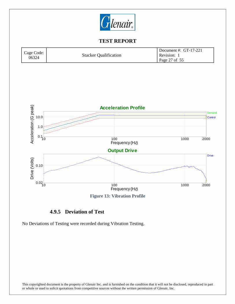
4.9.3 Test Method and Setup
Sample 1A and 2A were mounted to the vibration fixture as a mated pair on the fixture plate. Samples
underwent 4 hours of Sinusoidal Vibration in each axis. During vibration testing samples are
monitored electrically using a discontinuity tester. There cannot be a discontinuity greater than 1
microsecond during vibration testing at any time.
4.9.4 Test Results
Both samples 1A and 2A underwent vibration testing with no issues. Visually there was no damage to
either sample and both had no defects that would hinder their performance. At no time during
vibration testing was an electrical discontinuity of 1 microsecond or greater measured.
TEST REPORT
Cage Code:
06324 Stacker Qualification
Document #: GT-17-221
Revision: 1
Page 27 of 55
This copyrighted document is the property of Glenair Inc. and is furnished on the condition that it will not be disclosed, reproduced in part
or whole or used to solicit quotations from competitive sources without the written permission of Glenair, Inc.
Figure 13: Vibration Profile
4.9.5 Deviation of Test
No Deviations of Testing were recorded during Vibration Testing.
200010 100 10000.1
1.0
10.0
Frequency (Hz)Acce
lera
tio
n (
G p
ea
k)
Acceleration ProfileDemand
Control
200010 100 10000.02
0.10
Frequency (Hz)
Dri
ve
(V
olts
)
Output DriveDrive

TEST REPORT
Cage Code:
06324 Stacker Qualification
Document #: GT-17-221
Revision: 1
Page 28 of 55
This copyrighted document is the property of Glenair Inc. and is furnished on the condition that it will not be disclosed, reproduced in part
or whole or used to solicit quotations from competitive sources without the written permission of Glenair, Inc.
4.9.6 Photographs
Figure 14: Vibration Shaker and Discontinuity Tester Setup
Figure 15: Close up of Stacker Vibration Fixture

TEST REPORT
Cage Code:
06324 Stacker Qualification
Document #: GT-17-221
Revision: 1
Page 29 of 55
This copyrighted document is the property of Glenair Inc. and is furnished on the condition that it will not be disclosed, reproduced in part
or whole or used to solicit quotations from competitive sources without the written permission of Glenair, Inc.
4.10 Mechanical Shock
4.10.1 References Mini-Qual Test Plan (STACKER) based on MIL-DTL-55302G
MIL-DTL-55302G – Connectors, Printed Circuit Subassembly and Accessories
EIA-364-27 – Mechanical Shock (Specified Impulse) Test Procedure for Electrical
Connectors and Sockets
4.10.2 Test Equipment
Table 20: Mechanical Shock Test Equipment
Manufacturer Model Number Description Ling A395 Electrodynamic Shaker
Vibration Research VR9500 Vibration Controller
Dytran 3056D1 Accelerometer
4.10.3 Test Method and Setup
The mated samples 1A and 2A underwent one shock in each direction for a total of 6 shocks. EIA-
364-27, Test Condition G: Saw Tooth Shock Pulse. 100G peak acceleration. Samples were monitored
electrically using a discontinuity tester. There cannot be a discontinuity greater than 1 microsecond
during shock testing at any time.
4.10.4 Test Results
All testing was performed in accordance with EIA-364-27. Mated samples 1A and 2A underwent all
shock testing, no discontinuity of 1 microsecond or greater was measured at any time. Samples were
visually inspected and found to be undamaged and fully operational.

TEST REPORT
Cage Code:
06324 Stacker Qualification
Document #: GT-17-221
Revision: 1
Page 30 of 55
This copyrighted document is the property of Glenair Inc. and is furnished on the condition that it will not be disclosed, reproduced in part
or whole or used to solicit quotations from competitive sources without the written permission of Glenair, Inc.
Figure 16: Terminal Sawtooth Shock in Positive Direction
Figure 17: Terminal Sawtooth Shock in Negative Direction
-6 -4 -2 0 2 4 6 8 10 12-40
-20
0
20
40
60
80
100
120
Time (ms)
Accele
ratio
n (G
)
AccelerationDemand
Control
Ch1
-6 -4 -2 0 2 4 6 8 10 12-0.4-0.3-0.2-0.100.10.20.30.4
Time (ms)Dis
pla
ce
men
t (i
n)
DisplacementDemand
Control
-6 -4 -2 0 2 4 6 8 10 12-0.4-0.2
00.20.40.60.81.0
Time (ms)
Dri
ve (
Volt
s)
DriveDrive
-6 -4 -2 0 2 4 6 8 10 12 14-120
-100
-80
-60
-40
-20
0
20
40
Time (ms)
Accele
ratio
n (G
)
AccelerationDemand
Control
Ch1
-6 -4 -2 0 2 4 6 8 10 12 14-0.2-0.1
00.10.20.30.4
Time (ms)Dis
pla
ce
men
t (i
n)
DisplacementDemand
Control
-6 -4 -2 0 2 4 6 8 10 12 14-1.0-0.5
00.51.0
Time (ms)
Dri
ve (
Volt
s)
DriveDrive

TEST REPORT
Cage Code:
06324 Stacker Qualification
Document #: GT-17-221
Revision: 1
Page 31 of 55
This copyrighted document is the property of Glenair Inc. and is furnished on the condition that it will not be disclosed, reproduced in part
or whole or used to solicit quotations from competitive sources without the written permission of Glenair, Inc.
4.10.5 Deviation of Test
No Deviations of Testing were recorded during Mating and Unmating Force Testing.
4.10.6 Photographs
Please see section 4.9.6.

TEST REPORT
Cage Code:
06324 Stacker Qualification
Document #: GT-17-221
Revision: 1
Page 32 of 55
This copyrighted document is the property of Glenair Inc. and is furnished on the condition that it will not be disclosed, reproduced in part
or whole or used to solicit quotations from competitive sources without the written permission of Glenair, Inc.
4.11 Low Level Contact Resistance
4.11.1 References Mini-Qual Test Plan (STACKER) based on MIL-DTL-55302G
MIL-DTL-55302G – Connectors, Printed Circuit Subassembly and Accessories
EIA-364-23 – Low Level Contact Resistance Test Procedure for Electrical
Connectors and Sockets
4.11.2 Test Equipment
Table 21: Low Level Contact Resistance Test Equipment
Manufacturer Model Number Description Fluke 287 True RMS Digital Multimeter
Sorensen XHR 40-25 DC Power Supply
4.11.3 Test Method and Setup
Using the voltage drop method the low level contact resistance of 7 contacts on each sample 1A and
2A were measured. A test current of 0.1 amps DC was applied across the contact while the voltage
drop was measured. In order to probe the final side of the contact, virgin uninstalled contacts were
provided to be used as a mounting point for power supply. Voltage drop cannot exceed .3 millivolts.
4.11.4 Test Results
Table 22: Post Vibration and Shock Low Level Contact Resistance Results
Voltage drop per position (mV)
Sample Number 114 115 116 117 118 119 120 1A .165 .137 .143 .180 .115 .197 .153
2A .165 .137 .143 .180 .115 .197 .153
4.11.5 Deviation of Test
No Deviations of Testing were recorded during Low Level Contact Resistance Testing.
4.11.6 Photographs Please see Figure 12.

TEST REPORT
Cage Code:
06324 Stacker Qualification
Document #: GT-17-221
Revision: 1
Page 33 of 55
This copyrighted document is the property of Glenair Inc. and is furnished on the condition that it will not be disclosed, reproduced in part
or whole or used to solicit quotations from competitive sources without the written permission of Glenair, Inc.
4.12 Mating and Unmating Force
4.12.1 References Mini-Qual Test Plan (STACKER) based on MIL-DTL-55302G
MIL-DTL-55302G – Connectors, Printed Circuit Subassembly and Accessories
4.12.2 Test Equipment
Table 23: Mating and Unmating Force Test Equipment
Manufacturer Model Number Description Chatillon TCD200 200 lb Tensile Tester Load Frame
Chatillon DFIS 200 200 lb Load Cell
4.12.3 Test Method and Setup
Samples 1A and 2A were mounted in the same custom fixture used during Contact Life testing. All
test set up parameters were the same except for the rate of mating, which was set to 60 cycles per hour
per MIL-DTL-55302G para 4.5.4. The maximum mate or unmate force cannot exceed 30 lb.
4.12.4 Test Results
Table 24: Post Vibration and Shock Mating and Unmating Force
Sample Number Ultimate Mating Force lb Ultimate Un-mating Force lb 2A into 1A Mated Pair 25.0 19.75

TEST REPORT
Cage Code:
06324 Stacker Qualification
Document #: GT-17-221
Revision: 1
Page 34 of 55
This copyrighted document is the property of Glenair Inc. and is furnished on the condition that it will not be disclosed, reproduced in part
or whole or used to solicit quotations from competitive sources without the written permission of Glenair, Inc.
Figure 18: Sample 2A-1A Mating and Unmating Force Post Vibration and Shock
4.12.5 Deviation of Test
No Deviations of Testing were recorded during Mating and Unmating Force Testing.
4.12.6 Photographs
Please see Figure 10.
TEST REPORT
Cage Code:
06324 Stacker Qualification
Document #: GT-17-221
Revision: 1
Page 35 of 55
This copyrighted document is the property of Glenair Inc. and is furnished on the condition that it will not be disclosed, reproduced in part
or whole or used to solicit quotations from competitive sources without the written permission of Glenair, Inc.
5.0 Group 2 Testing
5.1 Contact Compliant Forces
5.1.1 References Mini-Qual Test Plan (STACKER) based on MIL-DTL-55302G
MIL-DTL-55302G – Connectors, Printed Circuit Subassembly and Accessories
5.1.2 Test Equipment
Table 25: Contact Compliant Forces Test Equipment
Manufacturer Model Number Description Instron 3366 2250 lb Tensile Tester
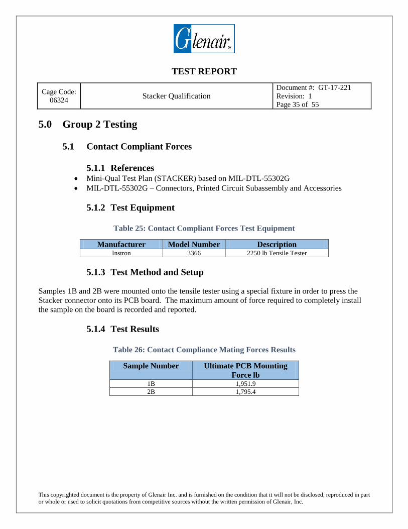
5.1.3 Test Method and Setup
Samples 1B and 2B were mounted onto the tensile tester using a special fixture in order to press the
Stacker connector onto its PCB board. The maximum amount of force required to completely install
the sample on the board is recorded and reported.
5.1.4 Test Results
Table 26: Contact Compliance Mating Forces Results
Sample Number Ultimate PCB Mounting
Force lb 1B 1,951.9
2B 1,795.4

TEST REPORT
Cage Code:
06324 Stacker Qualification
Document #: GT-17-221
Revision: 1
Page 36 of 55
This copyrighted document is the property of Glenair Inc. and is furnished on the condition that it will not be disclosed, reproduced in part
or whole or used to solicit quotations from competitive sources without the written permission of Glenair, Inc.
Figure 19: Contact Compliant Mating Forces of Sample 1B and 2B
5.1.5 Deviation of Test
No Deviations of Testing were recorded during Contact Compliance Forces Testing.
5.1.6 Photographs
Please see Figure 9.
-500
0
500
1000
1500
2000
2500
0 0.02 0.04 0.06 0.08 0.1 0.12 0.14 0.16
Load
(lb
f)
Distance (in)
PCB Mounting Force
1B
2B
TEST REPORT
Cage Code:
06324 Stacker Qualification
Document #: GT-17-221
Revision: 1
Page 37 of 55
This copyrighted document is the property of Glenair Inc. and is furnished on the condition that it will not be disclosed, reproduced in part
or whole or used to solicit quotations from competitive sources without the written permission of Glenair, Inc.
5.2 DWV at Sea Level
5.2.1 References Mini-Qual Test Plan (STACKER) based on MIL-DTL-55302G
MIL-DTL-55302G – Connectors, Printed Circuit Subassembly and Accessories
EIA-364-20 – Withstanding Voltage Test Procedure for Electrical Connectors, Sockets
and Coaxial Contacts
5.2.2 Test Equipment
Table 27: DWV at Sea Level Test Equipment
Manufacturer Model Number Description Associated Electronics Model 03770 HiPot Tester
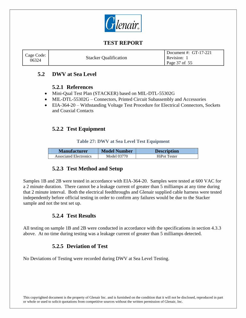
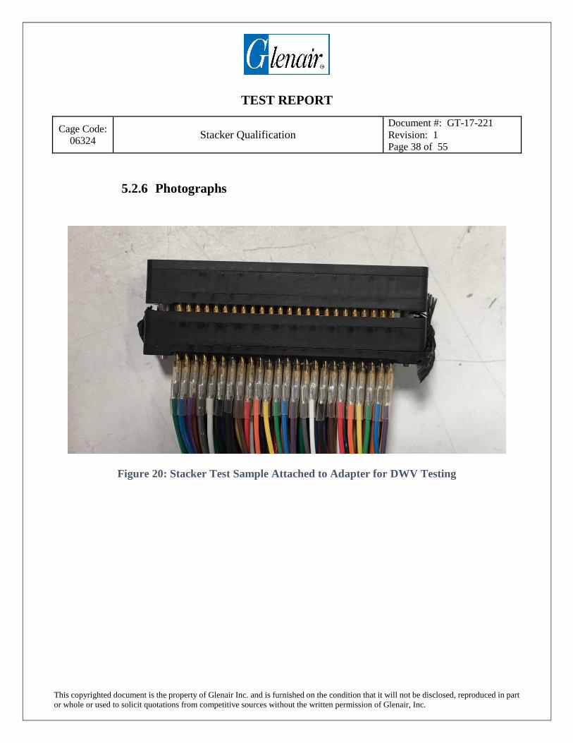
5.2.3 Test Method and Setup
Samples 1B and 2B were tested in accordance with EIA-364-20. Samples were tested at 600 VAC for
a 2 minute duration. There cannot be a leakage current of greater than 5 milliamps at any time during
that 2 minute interval. Both the electrical feedthroughs and Glenair supplied cable harness were tested
independently before official testing in order to confirm any failures would be due to the Stacker
sample and not the test set up.
5.2.4 Test Results
All testing on sample 1B and 2B were conducted in accordance with the specifications in section 4.3.3
above. At no time during testing was a leakage current of greater than 5 milliamps detected.
5.2.5 Deviation of Test
No Deviations of Testing were recorded during DWV at Sea Level Testing.
TEST REPORT
Cage Code:
06324 Stacker Qualification
Document #: GT-17-221
Revision: 1
Page 38 of 55
This copyrighted document is the property of Glenair Inc. and is furnished on the condition that it will not be disclosed, reproduced in part
or whole or used to solicit quotations from competitive sources without the written permission of Glenair, Inc.
5.2.6 Photographs
Figure 20: Stacker Test Sample Attached to Adapter for DWV Testing

TEST REPORT
Cage Code:
06324 Stacker Qualification
Document #: GT-17-221
Revision: 1
Page 39 of 55
This copyrighted document is the property of Glenair Inc. and is furnished on the condition that it will not be disclosed, reproduced in part
or whole or used to solicit quotations from competitive sources without the written permission of Glenair, Inc.
5.3 Insulation Resistance
5.3.1 References Mini-Qual Test Plan (STACKER) based on MIL-DTL-55302G
MIL-DTL-55302G – Connectors, Printed Circuit Subassembly and Accessories
EIA-364-21 – Insulation Resistance Test Procedure for Electrical Connectors, Sockets
and Coaxial Contacts
5.3.2 Test Equipment
Table 28: Insulation Resistance Test Equipment
Manufacturer Model Number Description Associated Electronics Model 03770 HiPot Tester
5.3.3 Test Method and Setup
Samples 1B and 2B were tested in accordance with EIA-364-21, 500 VDC for a duration of 2 minutes
or until 5,000 Megohms was reached. Identical test harness used for DWV testing was also to be used
for IR testing. Both the electrical feedthroughs and Glenair supplied cable harness were tested
independently before official testing in order to confirm any failures would be due to the Stacker
sample and not the test set up.
5.3.4 Test Results
Both samples reached 5,000 Megohms of resistance within 5 seconds. Visual inspection revealed no
damage to any of the test samples
5.3.5 Deviation of Test
No Deviations of Testing were recorded during Insulation Resistance Testing.
5.3.6 Photographs
Please see Figure 20.

TEST REPORT
Cage Code:
06324 Stacker Qualification
Document #: GT-17-221
Revision: 1
Page 40 of 55
This copyrighted document is the property of Glenair Inc. and is furnished on the condition that it will not be disclosed, reproduced in part
or whole or used to solicit quotations from competitive sources without the written permission of Glenair, Inc.
5.4 Temperature Cycling
5.4.1 References Mini-Qual Test Plan (STACKER) based on MIL-DTL-55302G
MIL-DTL-55302G – Connectors, Printed Circuit Subassembly and Accessories
EIA-364-32 – Thermal Shock (Temperature Cycling) Test Procedure for Electrical
Connectors and Sockets
5.4.2 Test Equipment
Table 29: Temperature Cycling Test Equipment
Manufacturer Model Number Description Ransco 9102 Thermal Shock Chamber
5.4.3 Test Method and Setup
Samples 1B and 2B were tested in accordance with EIA-364-32, Method A, Test Condition III,
requiring 5 cycles, -65°C to 85°C with 15 minute soak at each temperature extreme for 2.5 hour total
test duration.
5.4.4 Test Results
Visual Inspection revealed no damage to either sample 1B or 2B. See below for temperature profile.
Figure 21: Thermal Shock Temperature Profile

TEST REPORT
Cage Code:
06324 Stacker Qualification
Document #: GT-17-221
Revision: 1
Page 41 of 55
This copyrighted document is the property of Glenair Inc. and is furnished on the condition that it will not be disclosed, reproduced in part
or whole or used to solicit quotations from competitive sources without the written permission of Glenair, Inc.
5.4.5 Deviation of Test
No Deviations of Testing were recorded during Thermal Shock Testing.
5.4.6 Photographs
Figure 22: Samples Read for Thermal Shock Testing

TEST REPORT
Cage Code:
06324 Stacker Qualification
Document #: GT-17-221
Revision: 1
Page 42 of 55
This copyrighted document is the property of Glenair Inc. and is furnished on the condition that it will not be disclosed, reproduced in part
or whole or used to solicit quotations from competitive sources without the written permission of Glenair, Inc.
5.5 Contact Resistance
5.5.1 References Mini-Qual Test Plan (STACKER) based on MIL-DTL-55302G
MIL-DTL-55302G – Connectors, Printed Circuit Subassembly and Accessories
EIA-364-06 – Contact Resistance Test Procedure for Electrical Connectors
5.5.2 Test Equipment
Table 30: Contact Resistance Testing Equipment
Manufacturer Model Number Description Fluke 287 True RMS Digital Multimeter
Sorensen XHR 40-25 DC Power Supply
5.5.3 Test Method and Setup
Using the voltage drop method the low level contact resistance of 7 contacts on each sample 1B and
2B were measured. A test current of 5 amps DC was applied across the contact while the voltage drop
was measured. In order to probe the final side of the contact, virgin uninstalled contacts were provided
to be used as a mounting point for power supply. Voltage drop cannot exceed 75 millivolts.
5.5.4 Test Results
All samples were measured and no contact exceeded 75 millivolts of voltage drop.
Table 31: Post Thermal Shock Contact Resistance Results
Voltage drop per position (mV)
Sample Number 114 115 116 117 118 119 120 1B 11.38 7.40 7.04 6.02 9.30 6.05 6.78
2B 7.89 11.70 9.35 11.40 8.17 10.344 6.05

TEST REPORT
Cage Code:
06324 Stacker Qualification
Document #: GT-17-221
Revision: 1
Page 43 of 55
This copyrighted document is the property of Glenair Inc. and is furnished on the condition that it will not be disclosed, reproduced in part
or whole or used to solicit quotations from competitive sources without the written permission of Glenair, Inc.
5.5.5 Deviation of Test
No Deviations of Testing were recorded during Contact Resistance Testing.
5.5.6 Photographs
Please see Figure 12.

TEST REPORT
Cage Code:
06324 Stacker Qualification
Document #: GT-17-221
Revision: 1
Page 44 of 55
This copyrighted document is the property of Glenair Inc. and is furnished on the condition that it will not be disclosed, reproduced in part
or whole or used to solicit quotations from competitive sources without the written permission of Glenair, Inc.
5.6 Humidity Exposure
5.6.1 References Mini-Qual Test Plan (STACKER) based on MIL-DTL-55302G
MIL-DTL-55302G – Connectors, Printed Circuit Subassembly and Accessories
EIA-364-31- Humidity Test Procedure for Electrical Connectors and Sockets
5.6.2 Test Equipment
Table 32: Humidity Exposure Testing Equipment
Manufacturer Model Number Description Espec SH-220 Humidity Chamber
Dickson RH-2 Temp and Humidity Logger
5.6.3 Test Method and Setup
Samples 1B and 2B were tested in accordance with EIA-364-31, Method IV, which specifies 10
continuous 24 hour cycles. Samples were placed in the humidity chamber and not removed until all
humidity cycling was complete. Per MIL-DTL-55302G, steps 7a and 7b were not required.
5.6.4 Test Results
Visual Inspection revealed no damage to either of the test samples 1B or 2B. A small amount of
discoloration was visible on the contact surface.

TEST REPORT
Cage Code:
06324 Stacker Qualification
Document #: GT-17-221
Revision: 1
Page 45 of 55
This copyrighted document is the property of Glenair Inc. and is furnished on the condition that it will not be disclosed, reproduced in part
or whole or used to solicit quotations from competitive sources without the written permission of Glenair, Inc.
Figure 23: A Single Cycle of Humidity Exposure Testing
5.6.5 Deviation of Test
No Deviations of Testing were recorded during Humidity Exposure Testing.
80
85
90
95
100
105
20
25
30
35
40
45
50
55
60
65
70
2.1 2.3 2.5 2.7 2.9 3.1 3.3
Tem
per
atu
re in
Deg
rees
C
Time in Days
Stacker Humidity Testing
Temperature
Relative Humidity
Hu
mid
ity
in %
RH

TEST REPORT
Cage Code:
06324 Stacker Qualification
Document #: GT-17-221
Revision: 1
Page 46 of 55
This copyrighted document is the property of Glenair Inc. and is furnished on the condition that it will not be disclosed, reproduced in part
or whole or used to solicit quotations from competitive sources without the written permission of Glenair, Inc.
5.6.6 Photographs
Figure 24: Samples 2A and 2B ready for Humidity Exposure Testing
Figure 25: Small Amount of Discoloration Visible on Sample Contacts

TEST REPORT
Cage Code:
06324 Stacker Qualification
Document #: GT-17-221
Revision: 1
Page 47 of 55
This copyrighted document is the property of Glenair Inc. and is furnished on the condition that it will not be disclosed, reproduced in part
or whole or used to solicit quotations from competitive sources without the written permission of Glenair, Inc.
5.7 Insulation Resistance
5.7.1 References Mini-Qual Test Plan (STACKER) based on MIL-DTL-55302G
MIL-DTL-55302G – Connectors, Printed Circuit Subassembly and Accessories
EIA-364-21 – Insulation Resistance Test Procedure for Electrical Connectors,
Sockets and Coaxial Contacts
5.7.2 Test Equipment
Table 33: Insulation Resistance Test Equipment
Manufacturer Model Number Description Associated Electronics Model 03770 HiPot Tester
5.7.3 Test Method and Setup
Samples 1B and 2B were tested in accordance with EIA-364-21 for a duration of 2 minutes or until
5,000 Megohms was reached. Test voltage was 100 VDC per MIL-DTL-55302G. Identical test
harness use for DWV testing was also to be used for IR testing. Both the electrical feedthroughs and
Glenair supplied cable harness were tested independently before official testing in order to confirm any
failures would be due to the Stacker sample and not the test set up. Samples were conditioned in an
environmental chamber for 2 hours at 35C before IR testing was conducted, as specified in EIA-364-
21.
5.7.4 Test Results
Both samples 1B and 2B reached 5,000 Megohms of resistance within 5 seconds. Visual inspection
revealed no damage to any of the test samples caused because of IR testing.
5.7.5 Deviation of Test
No Deviations of Testing were recorded during Humidity Exposure Testing.
5.7.6 Photographs
Please see Figure 20.

TEST REPORT
Cage Code:
06324 Stacker Qualification
Document #: GT-17-221
Revision: 1
Page 48 of 55
This copyrighted document is the property of Glenair Inc. and is furnished on the condition that it will not be disclosed, reproduced in part
or whole or used to solicit quotations from competitive sources without the written permission of Glenair, Inc.
5.8 Contact Resistance
5.8.1 References Mini-Qual Test Plan (STACKER) based on MIL-DTL-55302G
MIL-DTL-55302G – Connectors, Printed Circuit Subassembly and Accessories
5.8.2 Test Equipment
Table 34: Contact Resistance Test Equipment
Manufacturer Model Number Description Fluke 287 True RMS Digital Multimeter
Sorensen XHR 40-25 DC Power Supply
5.8.3 Test Method and Setup
Using the voltage drop method the contact resistance of 7 contacts on each sample 1B and 2B were
measured. A test current of 5 amps DC was applied across the contact while the voltage drop was
measured. In order to probe the final side of the contact, virgin uninstalled contacts were provided to
be used as a mounting point for power supply. Voltage drop cannot exceed 75 millivolts.
5.8.4 Test Results
Table 35: Post Humidity Exposure Contact Resistance Results
Voltage drop per position (mV)
Sample Number 114 115 116 117 118 119 120 1B 6.94 7.33 6.05 6.25 10.87 6.97 10.30
2B 6.61 10.46 6.15 10.09 6.27 9.36 8.39
5.8.5 Deviation of Test
No Deviations of Testing were recorded during Contact Resistance Testing.
5.8.6 Photographs
Please see Figure 12.

TEST REPORT
Cage Code:
06324 Stacker Qualification
Document #: GT-17-221
Revision: 1
Page 49 of 55
This copyrighted document is the property of Glenair Inc. and is furnished on the condition that it will not be disclosed, reproduced in part
or whole or used to solicit quotations from competitive sources without the written permission of Glenair, Inc.
5.9 Low Level Contact Resistance
5.9.1 References Mini-Qual Test Plan (STACKER) based on MIL-DTL-55302G
MIL-DTL-55302G – Connectors, Printed Circuit Subassembly and Accessories
EIA-364-23 – Low Level Contact Resistance Test Procedure for Electrical
Connectors and Sockets
5.9.2 Test Equipment
Table 36: Low Level Contact Resistance Test Equipment
Manufacturer Model Number Description Fluke 287 True RMS Digital Multimeter
Sorensen XHR 40-25 DC Power Supply
5.9.3 Test Method and Setup Using the voltage drop method the low level contact resistance of 7 contacts on each sample 1B
and 2B were measured. A test current of 0.1 amps DC was applied across the contact while the
voltage drop was measured. In order to probe the final side of the contact, virgin uninstalled
contacts were provided to be used as a mounting point for power supply. Voltage drop
measurement cannot exceed .3 millivolts.
5.9.4 Test Results
Table 37: Low Level Contact Resistance Results
Voltage drop per position (mV)
Sample Number 114 115 116 117 118 119 120 1B .153 .165 .187 .173 .190 .159 .148
2B .182 .190 .201 .185 .172 .162 .208
5.9.5 Deviations of Test
No Deviations of Testing were recorded during Low Level Contact Resistance Testing.

TEST REPORT
Cage Code:
06324 Stacker Qualification
Document #: GT-17-221
Revision: 1
Page 50 of 55
This copyrighted document is the property of Glenair Inc. and is furnished on the condition that it will not be disclosed, reproduced in part
or whole or used to solicit quotations from competitive sources without the written permission of Glenair, Inc.
5.10 Mating and Unmating Force
5.10.1 References Mini-Qual Test Plan (STACKER) based on MIL-DTL-55302G
MIL-DTL-55302G – Connectors, Printed Circuit Subassembly and Accessories
5.10.2 Test Equipment
Table 38: Post Humidity Mating and Unmating Force Results
Manufacturer Model Number Description Chatillon TCD200 200 lb Tensile Tester Load Frame
Chatillon DFIS 200 200 lb Load Cell
5.10.3 Test Method and Setup
Samples 1B and 2B were mounted in the same custom fixture used during Contact Life testing. All
test set up parameters were the same except for the rate of mating, which was set to 60 cycles per hour
per MIL-DTL-55302G para 4.5.4. The maximum mate or unmate force cannot exceed 30 lb.
5.10.4 Test Results
Table 39: Post Humidity Mating and Unmating Force Results
Sample Number Ultimate Mating Force lb Ultimate Un-mating Force lb 2B into 1B Mated Pair 23.0 16.0

TEST REPORT
Cage Code:
06324 Stacker Qualification
Document #: GT-17-221
Revision: 1
Page 51 of 55
This copyrighted document is the property of Glenair Inc. and is furnished on the condition that it will not be disclosed, reproduced in part
or whole or used to solicit quotations from competitive sources without the written permission of Glenair, Inc.
Figure 26: Sample 2B-1B Post Humidity Mating and Unmating Force Trace
5.10.5 Deviation of Test
No Deviations of Testing were recorded during Mating and Unmating Force Testing.
5.10.6 Photographs
Please see Figure 10.

TEST REPORT
Cage Code:
06324 Stacker Qualification
Document #: GT-17-221
Revision: 1
Page 52 of 55
This copyrighted document is the property of Glenair Inc. and is furnished on the condition that it will not be disclosed, reproduced in part
or whole or used to solicit quotations from competitive sources without the written permission of Glenair, Inc.
5.11 Contact Compliant Removal Forces
5.11.1 References Mini-Qual Test Plan (STACKER) based on MIL-DTL-55302G
MIL-DTL-55302G – Connectors, Printed Circuit Subassembly and Accessories
5.11.2 Test Equipment
Table 40: Contact Compliant Removal Forces Test Equipment
Manufacturer Model Number Description Instron 3366 2250 lb Tensile Tester
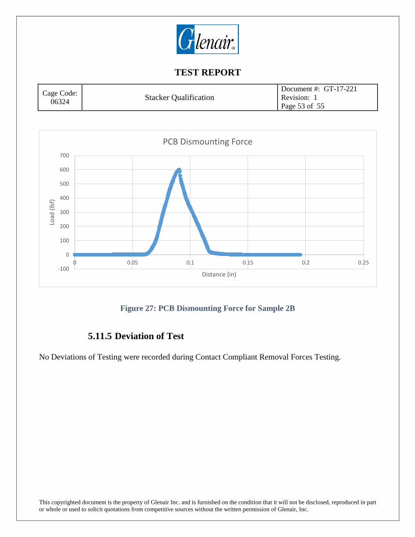
5.11.3 Test Method and Setup
Sample 2B was dismounted onto the tensile tester using a special fixture in order to release the Stacker
connector from its PCB board. The maximum amount of force required to completely remove the
sample from its board is recorded and reported.
5.11.4 Test Results
Table 41: Contact Compliant Removal Forces Results
Sample Number Ultimate PCB Mounting
Force 2B 600.90 lb
TEST REPORT
Cage Code:
06324 Stacker Qualification
Document #: GT-17-221
Revision: 1
Page 53 of 55
This copyrighted document is the property of Glenair Inc. and is furnished on the condition that it will not be disclosed, reproduced in part
or whole or used to solicit quotations from competitive sources without the written permission of Glenair, Inc.
Figure 27: PCB Dismounting Force for Sample 2B
5.11.5 Deviation of Test
No Deviations of Testing were recorded during Contact Compliant Removal Forces Testing.
-100
0
100
200
300
400
500
600
700
0 0.05 0.1 0.15 0.2 0.25
Load
(lb
f)
Distance (in)
PCB Dismounting Force

TEST REPORT
Cage Code:
06324 Stacker Qualification
Document #: GT-17-221
Revision: 1
Page 54 of 55
This copyrighted document is the property of Glenair Inc. and is furnished on the condition that it will not be disclosed, reproduced in part
or whole or used to solicit quotations from competitive sources without the written permission of Glenair, Inc.
5.11.6 Photographs
Figure 28: PCB Dismounting Fixture
Figure 29: Dismount Complete

TEST REPORT
Cage Code:
06324 Stacker Qualification
Document #: GT-17-221
Revision: 1
Page 55 of 55
This copyrighted document is the property of Glenair Inc. and is furnished on the condition that it will not be disclosed, reproduced in part
or whole or used to solicit quotations from competitive sources without the written permission of Glenair, Inc.
END OF REPORT