TEST REPORT DIN V VDE V 0126-1-1:2006 Automatic
23
Page 1 of 23 Report no. GZ10080033-1 TRF No. VDE0126-1-1A TEST REPORT DIN V VDE V 0126-1-1:2006 Automatic disconnecting device Report Reference No. ..................... : GZ10080033-1 Date of issue ..................................... : August 18, 2010 Total number of pages....................... 23 pages Testing Laboratory ......................... : Intertek Testing Services Shenzhen Ltd. Guangzhou Branch Address............................................. : Block E, No.7-2 Guang Dong Software Science Park, Caipin Road, Guangzhou Science City, GETDD, Guangzhou, China Tested by (name + signature) ........... : Jason Fu Approved by (name + signature) ....... : Grady Ye Applicant’s name ............................ : Zhejiang Tress Electronics Technology Co., Ltd. Address............................................. : Paiyantou Industrial Zone, Qiligang town, Yueqing, Wenzhou, Zhejiang, 325604 P.R.China Test specification: Standard ........................................... : DIN V VDE V 0126-1-1: 2006 Test procedure.................................. : Compliance testing Non-standard test method…………..: N/A Test Report Form No. ..................... : VDE0126-1-1A Test Report Form(s) Originator ........ : Intertek Master TRF ....................................... : Dated 2007-10 This publication may be reproduced in whole or in part for non-commercial purposes as long as Intertek is acknowledged as copyright owner and source of the material. Intertek takes no responsibility for and will not assume liability for damages resulting from the reader's interpretation of the reproduced material due to its placement and context. Test item description ..................... : Grid-connected PV inverter Trade Mark ....................................... : TRESS Manufacturer..................................... : Same as applicant Model/Type reference ....................... : TLS-ZB 3KW, TLS-ZB 4KW Ratings.............................................. : Input: 100-500Vdc, Nominal 360Vdc, MPPT 100-500Vdc; Protection against electric shock: Class I TLS-ZB 3KW: Output: 230V, 50Hz, Max 3000W TLS-ZB 4KW: Output: 230V, 50Hz, Max 4000W
Transcript of TEST REPORT DIN V VDE V 0126-1-1:2006 Automatic
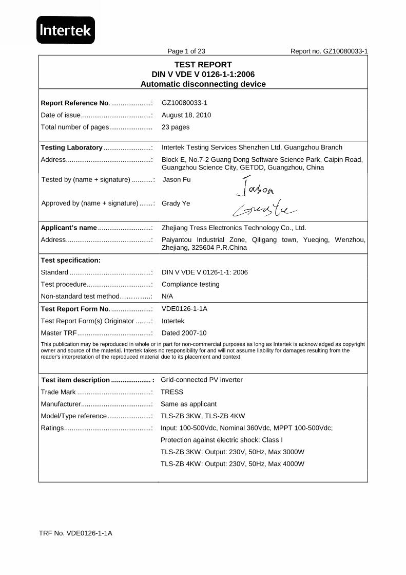
Page 1 of 23 Report no. GZ10080033-1
TRF No. VDE0126-1-1A
TEST REPORT DIN V VDE V 0126-1-1:2006
Automatic disconnecting device
Report Reference No . .....................: GZ10080033-1
Date of issue.....................................: August 18, 2010
Total number of pages....................... 23 pages
Testing Laboratory .........................: Intertek Testing Services Shenzhen Ltd. Guangzhou Branch
Address.............................................: Block E, No.7-2 Guang Dong Software Science Park, Caipin Road, Guangzhou Science City, GETDD, Guangzhou, China
Tested by (name + signature) ........... : Jason Fu
Approved by (name + signature) ....... : Grady Ye
Applicant’s name ............................: Zhejiang Tress Electronics Technology Co., Ltd.
Address.............................................: Paiyantou Industrial Zone, Qiligang town, Yueqing, Wenzhou, Zhejiang, 325604 P.R.China
Test specification:
Standard ...........................................: DIN V VDE V 0126-1-1: 2006
Test procedure..................................: Compliance testing
Non-standard test method…………..: N/A
Test Report Form No . .....................: VDE0126-1-1A
Test Report Form(s) Originator ........: Intertek
Master TRF.......................................: Dated 2007-10
This publication may be reproduced in whole or in part for non-commercial purposes as long as Intertek is acknowledged as copyright owner and source of the material. Intertek takes no responsibility for and will not assume liability for damages resulting from the reader's interpretation of the reproduced material due to its placement and context.
Test item description ..................... : Grid-connected PV inverter
Trade Mark .......................................: TRESS
Manufacturer.....................................: Same as applicant
Model/Type reference.......................: TLS-ZB 3KW, TLS-ZB 4KW
Ratings..............................................: Input: 100-500Vdc, Nominal 360Vdc, MPPT 100-500Vdc;
Protection against electric shock: Class I
TLS-ZB 3KW: Output: 230V, 50Hz, Max 3000W
TLS-ZB 4KW: Output: 230V, 50Hz, Max 4000W

Page 2 of 23 Report no. GZ10080033-1
TRF No. VDE0126-1-1A
Summary of testing:
Tests performed (name of test and test clause):
6.2 monitoring the voltage
6.3 monitoring the frequency
6.4 Monitoring the current
6.5.2 Detection of islanding operation – Test with resonance circuit
6.6.2.2.2 Monitoring of fault current – Test due to constantly rising fault current
6.6.2.2.3 Monitoring o fault current – Test due to fault current that occurs suddenly
6.6.2.2.4 Monitoring of fault current – Test of the detection of an insulation fault
Testing location:
Intertek Testing Services Shenzhen Ltd. Guangzhou Branch
Page 3 of 23 Report no. GZ10080033-1
TRF No. VDE0126-1-1A
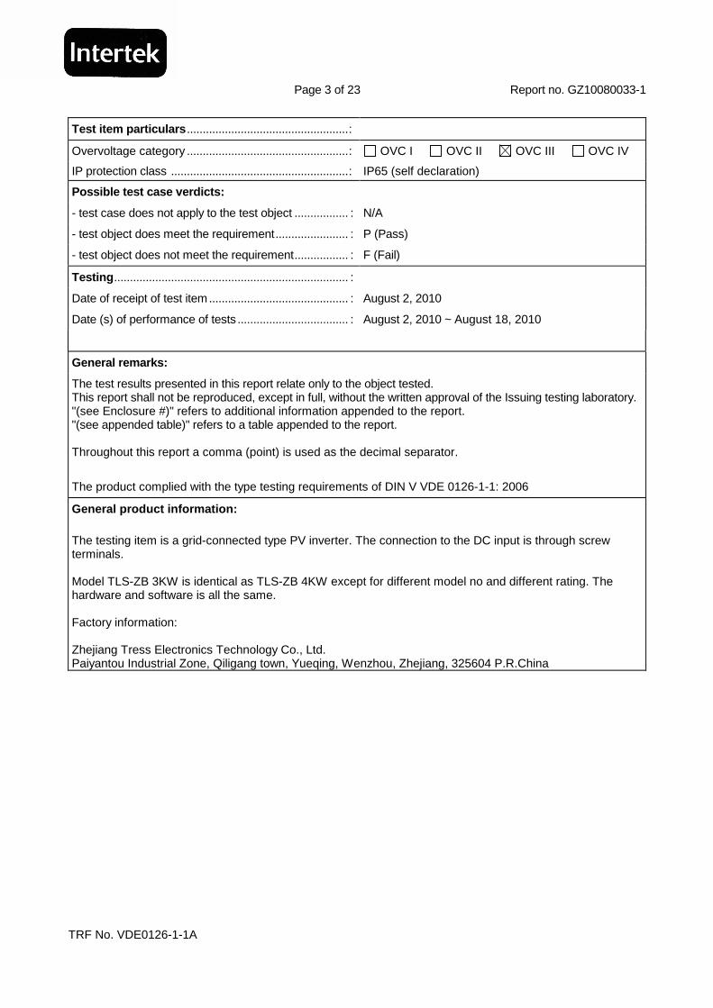
Test item particulars ...................................................:
Overvoltage category ...................................................: OVC I OVC II OVC III OVC IV
IP protection class ........................................................: IP65 (self declaration)
Possible test case verdicts:
- test case does not apply to the test object ................. : N/A
- test object does meet the requirement....................... : P (Pass)
- test object does not meet the requirement................. : F (Fail)
Testing .......................................................................... :
Date of receipt of test item............................................ : August 2, 2010
Date (s) of performance of tests ................................... : August 2, 2010 ~ August 18, 2010
General remarks:
The test results presented in this report relate only to the object tested. This report shall not be reproduced, except in full, without the written approval of the Issuing testing laboratory. "(see Enclosure #)" refers to additional information appended to the report. "(see appended table)" refers to a table appended to the report. Throughout this report a comma (point) is used as the decimal separator.
The product complied with the type testing requirements of DIN V VDE 0126-1-1: 2006
General product information:
The testing item is a grid-connected type PV inverter. The connection to the DC input is through screw terminals. Model TLS-ZB 3KW is identical as TLS-ZB 4KW except for different model no and different rating. The hardware and software is all the same. Factory information: Zhejiang Tress Electronics Technology Co., Ltd. Paiyantou Industrial Zone, Qiligang town, Yueqing, Wenzhou, Zhejiang, 325604 P.R.China
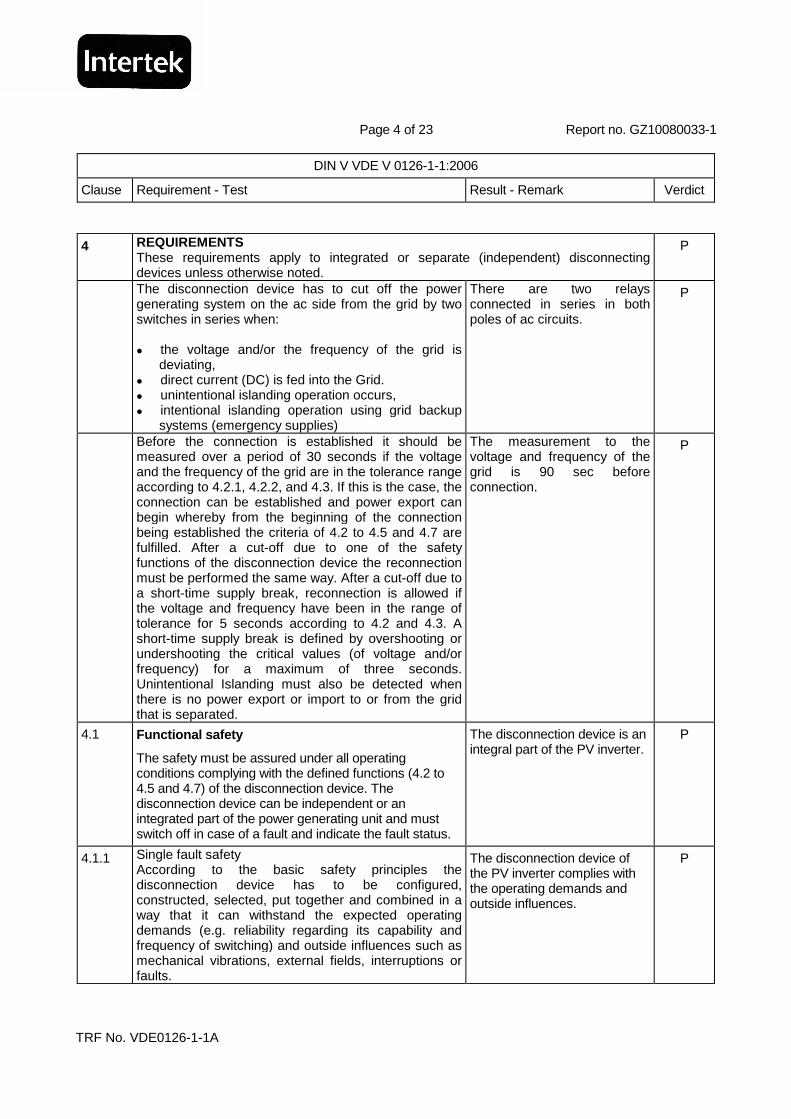
Page 4 of 23 Report no. GZ10080033-1
DIN V VDE V 0126-1-1:2006
Clause Requirement - Test Result - Remark Verdict
TRF No. VDE0126-1-1A
4 REQUIREMENTS These requirements apply to integrated or separate (independent) disconnecting devices unless otherwise noted.
P
The disconnection device has to cut off the power generating system on the ac side from the grid by two switches in series when: the voltage and/or the frequency of the grid is
deviating, direct current (DC) is fed into the Grid. unintentional islanding operation occurs, intentional islanding operation using grid backup
systems (emergency supplies)
There are two relays connected in series in both poles of ac circuits.
P
Before the connection is established it should be measured over a period of 30 seconds if the voltage and the frequency of the grid are in the tolerance range according to 4.2.1, 4.2.2, and 4.3. If this is the case, the connection can be established and power export can begin whereby from the beginning of the connection being established the criteria of 4.2 to 4.5 and 4.7 are fulfilled. After a cut-off due to one of the safety functions of the disconnection device the reconnection must be performed the same way. After a cut-off due to a short-time supply break, reconnection is allowed if the voltage and frequency have been in the range of tolerance for 5 seconds according to 4.2 and 4.3. A short-time supply break is defined by overshooting or undershooting the critical values (of voltage and/or frequency) for a maximum of three seconds. Unintentional Islanding must also be detected when there is no power export or import to or from the grid that is separated.
The measurement to the voltage and frequency of the grid is 90 sec before connection.
P
4.1 Functional safety
The safety must be assured under all operating conditions complying with the defined functions (4.2 to 4.5 and 4.7) of the disconnection device. The disconnection device can be independent or an integrated part of the power generating unit and must switch off in case of a fault and indicate the fault status.
The disconnection device is an integral part of the PV inverter.
P
4.1.1 Single fault safety According to the basic safety principles the disconnection device has to be configured, constructed, selected, put together and combined in a way that it can withstand the expected operating demands (e.g. reliability regarding its capability and frequency of switching) and outside influences such as mechanical vibrations, external fields, interruptions or faults.
The disconnection device of the PV inverter complies with the operating demands and outside influences.
P
Page 5 of 23 Report no. GZ10080033-1
DIN V VDE V 0126-1-1:2006
Clause Requirement - Test Result - Remark Verdict
TRF No. VDE0126-1-1A
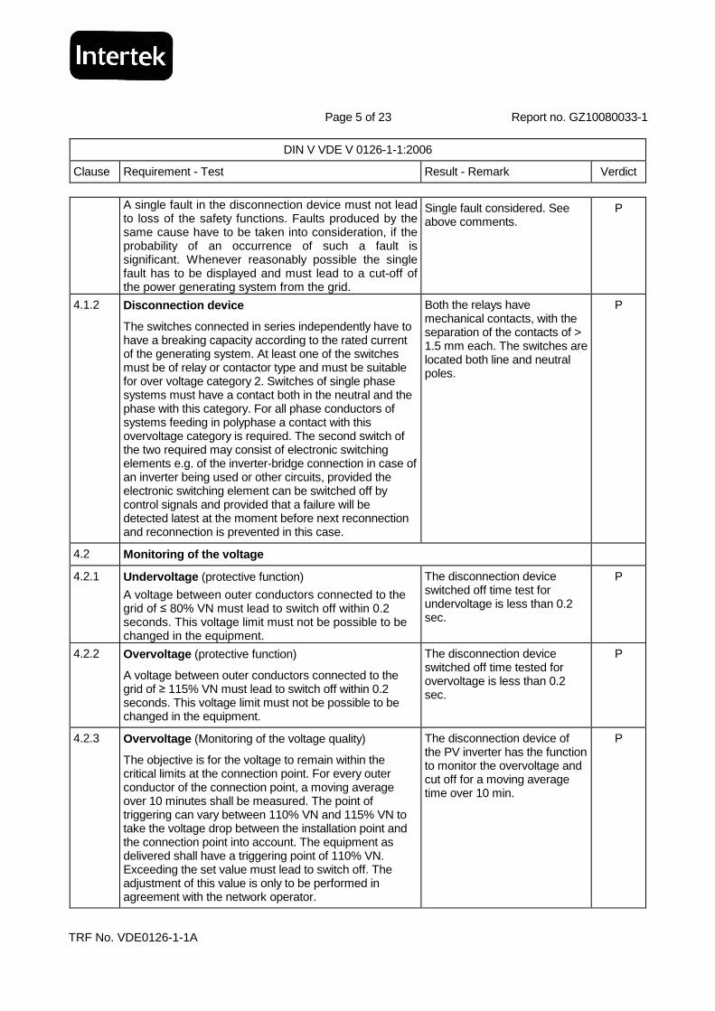
A single fault in the disconnection device must not lead to loss of the safety functions. Faults produced by the same cause have to be taken into consideration, if the probability of an occurrence of such a fault is significant. Whenever reasonably possible the single fault has to be displayed and must lead to a cut-off of the power generating system from the grid.
Single fault considered. See above comments.
P
4.1.2 Disconnection device
The switches connected in series independently have to have a breaking capacity according to the rated current of the generating system. At least one of the switches must be of relay or contactor type and must be suitable for over voltage category 2. Switches of single phase systems must have a contact both in the neutral and the phase with this category. For all phase conductors of systems feeding in polyphase a contact with this overvoltage category is required. The second switch of the two required may consist of electronic switching elements e.g. of the inverter-bridge connection in case of an inverter being used or other circuits, provided the electronic switching element can be switched off by control signals and provided that a failure will be detected latest at the moment before next reconnection and reconnection is prevented in this case.
Both the relays have mechanical contacts, with the separation of the contacts of > 1.5 mm each. The switches are located both line and neutral poles.
P
4.2 Monitoring of the voltage
4.2.1 Undervoltage (protective function)
A voltage between outer conductors connected to the grid of ≤ 80% VN must lead to switch off within 0.2 seconds. This voltage limit must not be possible to be changed in the equipment.
The disconnection device switched off time test for undervoltage is less than 0.2 sec.
P
4.2.2 Overvoltage (protective function)
A voltage between outer conductors connected to the grid of ≥ 115% VN must lead to switch off within 0.2 seconds. This voltage limit must not be possible to be changed in the equipment.
The disconnection device switched off time tested for overvoltage is less than 0.2 sec.
P
4.2.3 Overvoltage (Monitoring of the voltage quality)
The objective is for the voltage to remain within the critical limits at the connection point. For every outer conductor of the connection point, a moving average over 10 minutes shall be measured. The point of triggering can vary between 110% VN and 115% VN to take the voltage drop between the installation point and the connection point into account. The equipment as delivered shall have a triggering point of 110% VN. Exceeding the set value must lead to switch off. The adjustment of this value is only to be performed in agreement with the network operator.
The disconnection device of the PV inverter has the function to monitor the overvoltage and cut off for a moving average time over 10 min.
P

Page 6 of 23 Report no. GZ10080033-1
DIN V VDE V 0126-1-1:2006
Clause Requirement - Test Result - Remark Verdict
TRF No. VDE0126-1-1A
4.3 Monitoring the frequency
Frequencies undershooting 47.5 Hz or exceeding 50.2 Hz must lead to a switch off within 0.2 seconds.
The switched off time tested for under/over frequency is less than 0.2 s.
P
4.4 Monitoring the d.c. current
A feed in of d.c current into the low-voltage grid due to defective equipment must lead to a switch off within 0.2 seconds.
The measured disconnection time is less than 0.2 s.
P
4.5 Detection of islanding
4.5.1 Single equipment operation
Islanding operation must lead to switch off according to test conditions of the type test in 6.5.
MCPU of the inverter system is trying to change (increase) the mains frequency by adding a current disturbance to the output current. The mains frequency will be shifted outside the limit once the mains is not appeared and such deviation will be detected by CPU and the disconnection devices be switched off.
P
4.5.2 Multiple equipment operation
The identification of separate mains (grids) operation can be realised individually for each system so that each system fulfils the requirements of 4.5.1. Alternatively the automatic disconnection device can receive orders requiring a cut-off from an equivalent protector with islanding detection function via an interface. A cut-off order must be carried out within 0.2 seconds. The protector giving the cut-off orders as well as the interface have to fulfil the requirements of 4.1.1 regarding functional safety.
The tested item is single equipment operation.
N/A
4.7 Special requirements
4.7.1 Photovoltaic
Inverters without a basic insulation (e.g. basic insulated transformer) between the grid and the photovoltaic-Generator must have a fault current monitoring unit (RCMU) installed. The d.c. and a.c. component of the fault current depend on the construction of the inverter and on the d.c. voltage of the PV-generator.
P
A switching point without an integrated RCMU must have an external fault current protector. In this case the tests mentioned in 6.6 are not necessary. The required type of protector has to be specified in the manual by the manufacturer.
N/A
Page 7 of 23 Report no. GZ10080033-1
DIN V VDE V 0126-1-1:2006
Clause Requirement - Test Result - Remark Verdict
TRF No. VDE0126-1-1A
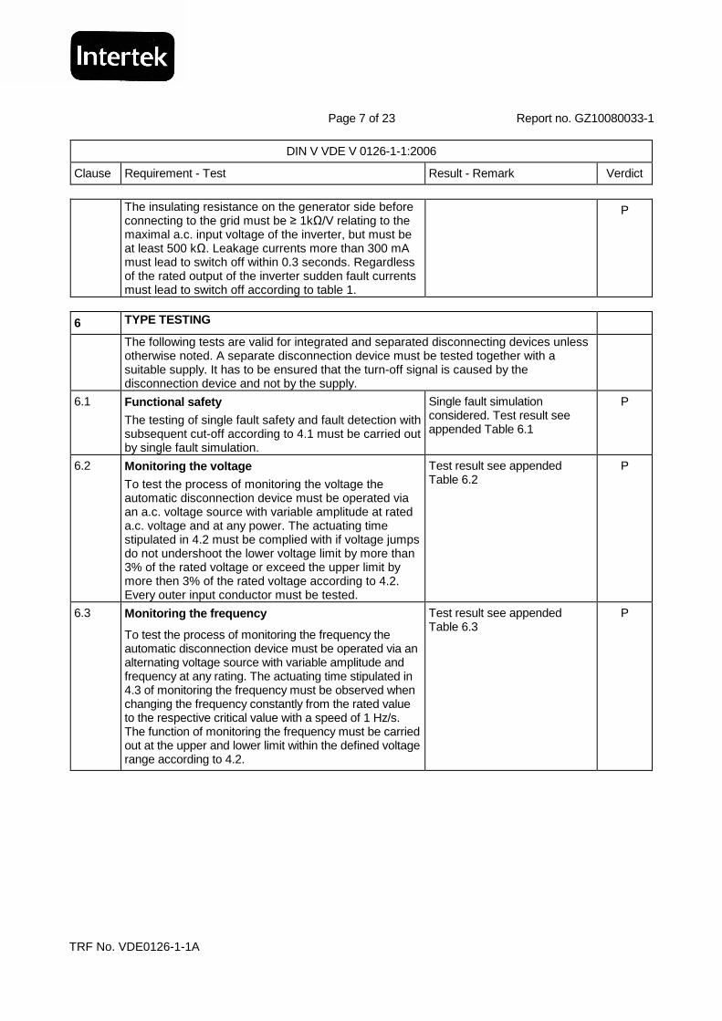
The insulating resistance on the generator side before connecting to the grid must be ≥ 1kΩ/V relating to the maximal a.c. input voltage of the inverter, but must be at least 500 kΩ. Leakage currents more than 300 mA must lead to switch off within 0.3 seconds. Regardless of the rated output of the inverter sudden fault currents must lead to switch off according to table 1.
P
6 TYPE TESTING
The following tests are valid for integrated and separated disconnecting devices unless otherwise noted. A separate disconnection device must be tested together with a suitable supply. It has to be ensured that the turn-off signal is caused by the disconnection device and not by the supply.
6.1 Functional safety
The testing of single fault safety and fault detection with subsequent cut-off according to 4.1 must be carried out by single fault simulation.
Single fault simulation considered. Test result see appended Table 6.1
P
6.2 Monitoring the voltage
To test the process of monitoring the voltage the automatic disconnection device must be operated via an a.c. voltage source with variable amplitude at rated a.c. voltage and at any power. The actuating time stipulated in 4.2 must be complied with if voltage jumps do not undershoot the lower voltage limit by more than 3% of the rated voltage or exceed the upper limit by more then 3% of the rated voltage according to 4.2. Every outer input conductor must be tested.
Test result see appended Table 6.2
P
6.3 Monitoring the frequency
To test the process of monitoring the frequency the automatic disconnection device must be operated via an alternating voltage source with variable amplitude and frequency at any rating. The actuating time stipulated in 4.3 of monitoring the frequency must be observed when changing the frequency constantly from the rated value to the respective critical value with a speed of 1 Hz/s. The function of monitoring the frequency must be carried out at the upper and lower limit within the defined voltage range according to 4.2.
Test result see appended Table 6.3
P

Page 8 of 23 Report no. GZ10080033-1
DIN V VDE V 0126-1-1:2006
Clause Requirement - Test Result - Remark Verdict
TRF No. VDE0126-1-1A
6.4 Monitoring the dc current
To test the process of cut-off due to feed in of direct current one of the followings may be chosen:
a) The measuring device at the switching point (e.g. current transformer or resistance) is fed with direct current of 1 A. The cut-off must be carried out within 0.2 seconds.
b) By means of a fault simulation it is measured if a defective system operation with a d.c. fault current of more than 1 A leads to cut-off within 0.2 seconds.
Method a) was used.
Test result see appended Table 6.4
P
6.5 Detection of islanding operation
To test the process of cut-off due to unintentional islanding a test must be carried out according to one of the procedures described in 6.5.1 to 6.5.3. The applied procedure must comply with the requirements regarding functional safety described in 4.1.
Method of resonance circuit is used for testing.
P
6.5.1 Measurement of the impedance N/A
6.5.1.1 Test circuit according to Figure 2. N/A
6.5.1.2 Test procedure according to the standard. N/A
6.5.2 Test with resonance circuit according to Figure 3. P
6.5.2.2 Test procedure according to the standard. P
6.5.3 Monitoring of three phase voltage
Only single phase inverters may use three-phase monitoring of the outer voltages as criteria for islanding condition. As soon as one of the outer conductor voltages exceeds the critical value described in 4.2 by 80% UN or 115% UN a cut-off within 0.2 seconds must be carried out. Here the requirements of 4.1 regarding functional safety must also be fulfilled.
Complied by subclause 6.5.2 N/A
6.6 Monitoring of fault current
All tests have to be carried out at 0.85 UN, UN, 1.10 UN.
See appended table 6.6 P
6.6.1 Separate disconnection device
Fault current detection that is not integrated in the inverter is tested according to DIN EN 0664-100 (VDE 0664-100): 2002-05.
Integral type disconnection device.
N/A
Page 9 of 23 Report no. GZ10080033-1
DIN V VDE V 0126-1-1:2006
Clause Requirement - Test Result - Remark Verdict
TRF No. VDE0126-1-1A
For this purpose 9.9.1 “testing circuit” to 9.9.3 “testing of function under load at reference temperature” must be applied. One has to be aware that the switch device can switch on with delay when testing according to 9.9.2.2 “Test of function when closing on a fault current”.
N/A
The time between the automatic switch on and the cut-off due to fault current is considered to be the turn-off time.
N/A
The function of pulsating d.c. fault currents is tested according to 9.21.1. The function of smooth d.c. fault currents is tested according to 9.21.2.1 “testing the function with a constant rise of the d.c. fault current” to 9.21.2.7 “testing the function with superimposed pulsating d.c. fault currents and smooth d.c. fault currents”.
N/A
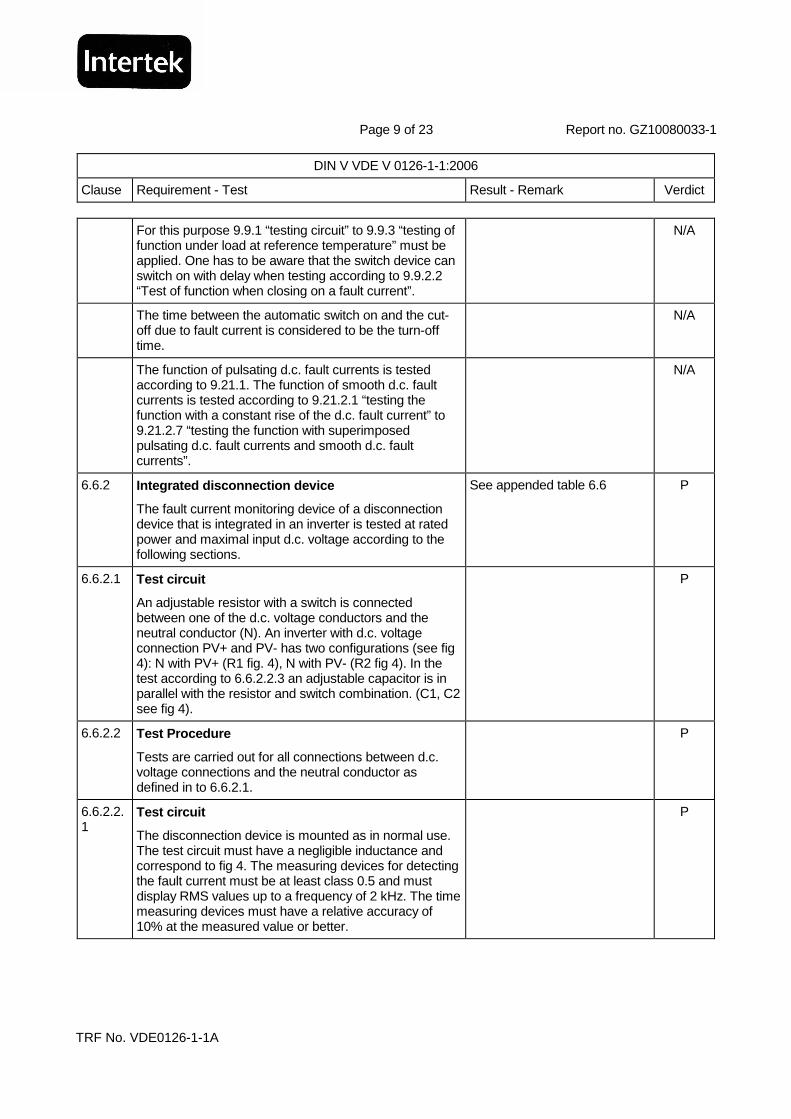
6.6.2 Integrated disconnection device
The fault current monitoring device of a disconnection device that is integrated in an inverter is tested at rated power and maximal input d.c. voltage according to the following sections.
See appended table 6.6 P
6.6.2.1 Test circuit
An adjustable resistor with a switch is connected between one of the d.c. voltage conductors and the neutral conductor (N). An inverter with d.c. voltage connection PV+ and PV- has two configurations (see fig 4): N with PV+ (R1 fig. 4), N with PV- (R2 fig 4). In the test according to 6.6.2.2.3 an adjustable capacitor is in parallel with the resistor and switch combination. (C1, C2 see fig 4).
P
6.6.2.2 Test Procedure
Tests are carried out for all connections between d.c. voltage connections and the neutral conductor as defined in to 6.6.2.1.
P
6.6.2.2.1
Test circuit
The disconnection device is mounted as in normal use. The test circuit must have a negligible inductance and correspond to fig 4. The measuring devices for detecting the fault current must be at least class 0.5 and must display RMS values up to a frequency of 2 kHz. The time measuring devices must have a relative accuracy of 10% at the measured value or better.
P
Page 10 of 23 Report no. GZ10080033-1
DIN V VDE V 0126-1-1:2006
Clause Requirement - Test Result - Remark Verdict
TRF No. VDE0126-1-1A
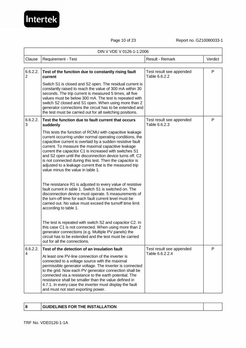
6.6.2.2.2
Test of the function due to constantly rising fault current
Switch S1 is closed and S2 open. The residual current is constantly raised to reach the value of 300 mA within 30 seconds. The trip current is measured 5 times, all five values must be below 300 mA. The test is repeated with switch S2 closed and S1 open. When using more than 2 generator connections the circuit has to be extended and the test must be carried out for all switching positions.
Test result see appended Table 6.6.2.2
P
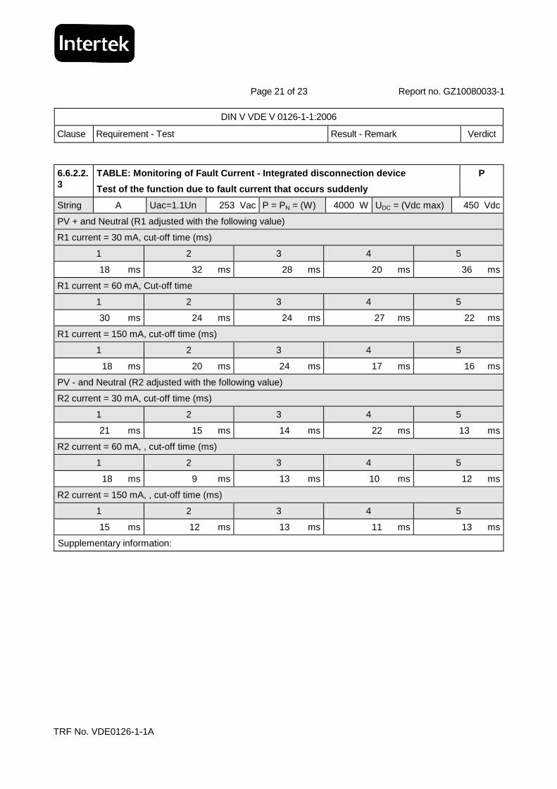
6.6.2.2.3
Test the function due to fault current that occurs suddenly
This tests the function of RCMU with capacitive leakage current occurring under normal operating conditions, the capacitive current is overlaid by a sudden resistive fault current. To measure the maximal capacitive leakage current the capacitor C1 is increased with switches S1 and S2 open until the disconnection device turns off. C2 is not connected during this test. Then the capacitor is adjusted to a leakage current that is the measured trip value minus the value in table 1.
The resistance R1 is adjusted to every value of resistive fault current in table 1. Switch S1 is switched on. The disconnection device must operate. 5 measurements of the turn-off time for each fault current level must be carried out. No value must exceed the turnoff time limit according to table 1.
The test is repeated with switch S2 and capacitor C2. In this case C1 is not connected. When using more than 2 generator connections (e.g. Multiple PV panels) the circuit has to be extended and the test must be carried out for all the connections.
Test result see appended Table 6.6.2.3
P
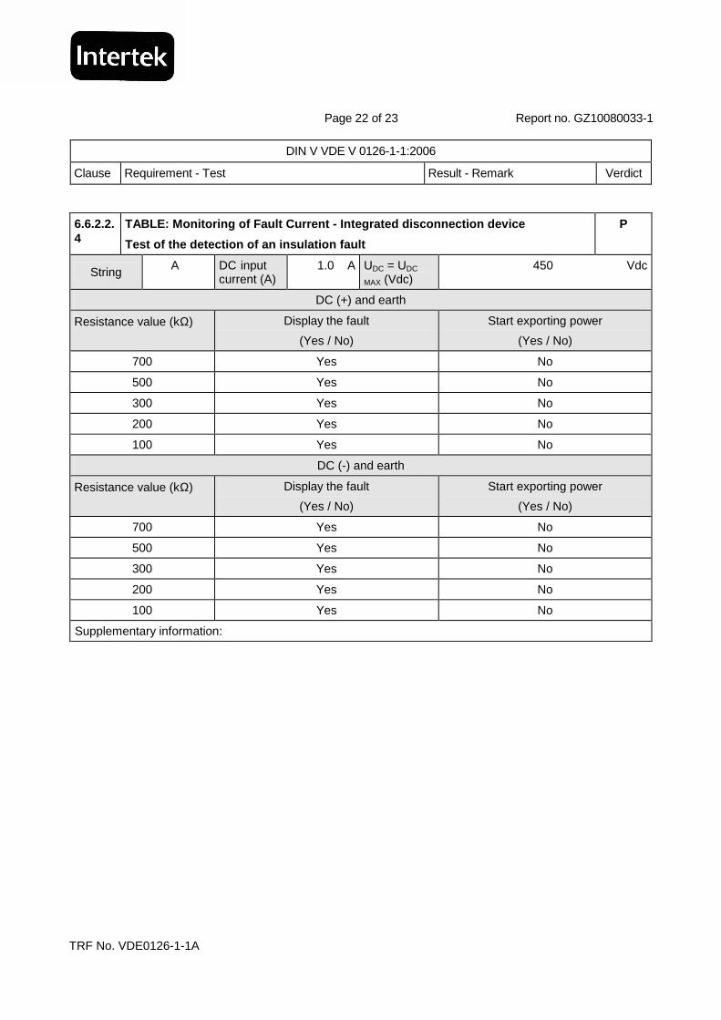
6.6.2.2.4
Test of the detection of an insulation fault
At least one PV-line connection of the inverter is connected to a voltage source with the maximal permissible generator voltage. The inverter is connected to the grid. Now each PV generator connection shall be connected via a resistance to the earth potential. The resistance shall be smaller than the value defined in 4.7.1. In every case the inverter must display the fault and must not start exporting power.
Test result see appended Table 6.6.2.2.4
P
8 GUIDELINES FOR THE INSTALLATION
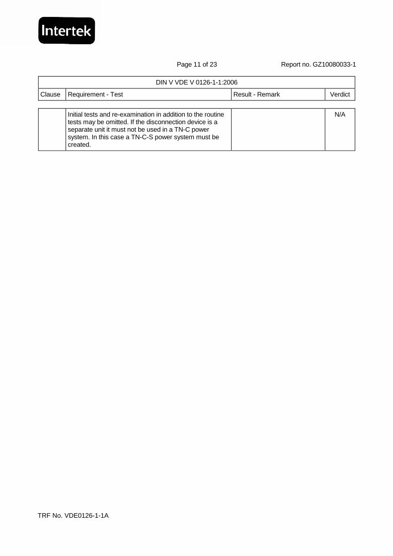
Page 11 of 23 Report no. GZ10080033-1
DIN V VDE V 0126-1-1:2006
Clause Requirement - Test Result - Remark Verdict
TRF No. VDE0126-1-1A
Initial tests and re-examination in addition to the routine tests may be omitted. If the disconnection device is a separate unit it must not be used in a TN-C power system. In this case a TN-C-S power system must be created.
N/A

Page 12 of 23 Report no. GZ10080033-1
DIN V VDE V 0126-1-1:2006
Clause Requirement - Test Result - Remark Verdict
TRF No. VDE0126-1-1A
Appended Table - Testing Result
6.1 TABLE: Single fault test P
Component Fault Observation
C105 Short circuit Inverter switch off
Alarm and “Over voltage” registered in display panel
DCT102 Short circuit Inverter switch off
Alarm and “Over voltage” registered in display panel
DCT101 Short circuit Inverter switch off
Alarm and “Over current” registered in display panel
DCT103 Short circuit Inverter switch off
Alarm and “Over load” registered in display panel
U702 Short circuit Inverter switch off Alarm and “Over heat” registered in display panel
D503 Short circuit Inverter switch off
D507 Short circuit Inverter switch off
Z605 Short circuit Inverter switch off Alarm and “Line failure” registered in display panel
C105 Short circuit Inverter switch off Alarm and “Fuse open” registered in display panel
D201 Short circuit Inverter switch off Alarm and “Line failure” registered in display panel
D207 Short circuit Inverter switch off Alarm and “Line failure” registered in display panel
Q15 Short circuit Inverter switch off

Page 13 of 23 Report no. GZ10080033-1
DIN V VDE V 0126-1-1:2006
Clause Requirement - Test Result - Remark Verdict
TRF No. VDE0126-1-1A
6.2.1 TABLE: Undervoltage test P
P = 1.0 PN = (W) 4000 W
Undervoltage, U =0.785 (Un) 195.5 Vac Cut-off time = (ms) 16.0 ms
Undervoltage, U = 0.5 (Un) 115 Vac Cut-off time = (ms) 17.0 ms
Undervoltage, U = 0 (Un) 0 Vac Cut-off time = (ms) --
P = 0.5 PN = (W) 2000 W
Undervoltage, U =0.785 (Un) 195.5 Vac Cut-off time = (ms) 13.0 ms
Undervoltage, U = 0.5 (Un) 115 Vac Cut-off time = (ms) 19.0 ms
Undervoltage, U = 0 (Un) 0 Vac Cut-off time = (ms) --
P = 0.25 PN = (W) 1000 W
Undervoltage, U =0.785 (Un) 195.5 Vac Cut-off time = (ms) 14.0 ms
Undervoltage, U = 0.5 (Un) 115 Vac Cut-off time = (ms) 16.0 ms
Undervoltage, U = 0 (Un) 0 Vac Cut-off time = (ms) --
Supplementary information:
6.2.2 TABLE: Overvoltage test P
P = 1.0 PN = (W) 4000 W
Overvoltage, U =1.165 (Un) 265 Vac Cut-off time = (ms) 28.0 ms
Overvoltage, U =1.3 (Un) 299 Vac Cut-off time = (ms) 37.0 ms
P = 0.5 PN = (W) 2000 W
Overvoltage, U =1.165 (Un) 265 Vac Cut-off time = (ms) 42.0 ms
Overvoltage, U =1.3 (Un) 299 Vac Cut-off time = (ms) 41.0 ms
P = 0.25 PN = (W) 1000 W
Overvoltage, U =1.165 (Un) 265 Vac Cut-off time = (ms) 36.0 ms
Overvoltage, U =1.3 (Un) 299 Vac Cut-off time = (ms) 43.0 ms
Supplementary information:

Page 14 of 23 Report no. GZ10080033-1
DIN V VDE V 0126-1-1:2006
Clause Requirement - Test Result - Remark Verdict
TRF No. VDE0126-1-1A
6.3 TABLE: Monitoring the frequency (Exceeding 50.2 Hz) P
P = 1.0 PN = (W) 4000 W
Upper voltage, U = 1.10 UN (Vac) 253 Vac Frequency (Hz) 50.5 Hz Cut-off time = 198 ms
Lower voltage, U = 0.85 UN (Vac) 195.5 Vac Frequency (Hz) 50.5 Hz Cut-off time = 189 ms
P = 0.5 PN = (W) 2000 W
Upper voltage, U = 1.10 UN (Vac) 253 Vac Frequency (Hz) 50.5 Hz Cut-off time = 190 ms
Lower voltage, U = 0.85 UN (Vac) 195.5 Vac Frequency (Hz) 50.5 Hz Cut-off time = 185 ms
P = 0.25 PN = (W) 1000 W
Upper voltage, U = 1.10 UN (Vac) 253 Vac Frequency (Hz) 50.5 Hz Cut-off time = 191 ms
Lower voltage, U = 0.85 UN (Vac) 195.5 Vac Frequency (Hz) 50.5 Hz Cut-off time = 184 ms
Supplementary information:
6.3 TABLE: Monitoring the frequency (undershooting 47.5 Hz) P
P = 1.0 PN = (W) 4000 W
Upper voltage, U = 1.10 UN (Vac) 253 Vac Frequency (Hz) 47.4 Hz Cut-off time = 82 ms
Lower voltage, U = 0.85 UN (Vac) 195.5 Vac Frequency (Hz) 47.4 Hz Cut-off time = 85 ms
P = 0.5 PN = (W) 2000 W
Upper voltage, U = 1.10 UN (Vac) 253 Vac Frequency (Hz) 47.4 Hz Cut-off time = 91 ms
Lower voltage, U = 0.85 UN (Vac) 195.5 Vac Frequency (Hz) 47.4 Hz Cut-off time = 87 ms
P = 0.25 PN = (W) 1000 W
Upper voltage, U = 1.10 UN (Vac) 253 Vac Frequency (Hz) 47.4 Hz Cut-off time = 85 ms
Lower voltage, U = 0.85 UN (Vac) 195.5 Vac Frequency (Hz) 47.4 Hz Cut-off time = 86 ms
Supplementary information:
6.4 TABLE: Monitoring the current P
P = 0.25 PN= (W) 4000 W
Feed-in current = 1.0 A d.c., Cut-off current = (ms) 19.4 ms
P = 0.5 PN= (W) 2000 W
Feed-in current = 1.0 A d.c., Cut-off current = (ms) 25.2 ms
P = 1.0 PN= (W) 1000 W
Feed-in current = 1.0 A d.c., Cut-off current = (ms) 22.1 ms
Supplementary information:

Page 15 of 23 Report no. GZ10080033-1
DIN V VDE V 0126-1-1:2006
Clause Requirement - Test Result - Remark Verdict
TRF No. VDE0126-1-1A
6.5.2 TABLE: Detection of Islanding Operation - Tes t with resonance circuit P
Q = 2.0 Klirrfactor = (%) -- %
L = (mH) -- mH L = (Var) 6500 Var C = (uF) -- uF C = (Var) 7115 Var
Rated Frequency = (Hz) 50 Hz Rated Voltage = (Vac) 230 Vac
P = 1.0 PN = (W) 3250 W
L Load Q(Var) C Load Q(Var) Cut-off time (ms)
100% 6500 100% 7115 912
101% 6436 100% 7115 864
102% 6373 100% 7115 880
103% 6311 100% 7115 912
104% 6250 100% 7115 864
105% 6190 100% 7115 904
99% 6566 100% 7115 810
98% 6633 100% 7115 924
97% 6701 100% 7115 876
96% 6771 100% 7115 796
95% 6842 100% 7115 772
100% 6500 101% 7186 880
100% 6500 102% 7257 856
100% 6500 103% 7328 920
100% 6500 104% 7400 888
100% 6500 105% 7471 912
100% 6500 99% 7044 892
100% 6500 98% 6973 532
100% 6500 97% 6902 500
100% 6500 96% 6830 556
100% 6500 95% 6759 492
Supplementary information:

Page 16 of 23 Report no. GZ10080033-1
DIN V VDE V 0126-1-1:2006
Clause Requirement - Test Result - Remark Verdict
TRF No. VDE0126-1-1A
L = (mH) -- mH L = (Var) 3912 Var C = (uF) -- uF C = (Var) 4462 Var
Rated Frequency = (Hz) 50 Hz Rated Voltage = (Vac) 230 Vac
P = 0.5 PN = (W) 1956 W
L Load Q(Var) C Load Q(Var) Cut-off time (ms)
100% 3912 100% 4462 800
101% 3873 100% 4462 832
102% 3835 100% 4462 800
103% 3798 100% 4462 784
104% 3762 100% 4462 768
105% 3726 100% 4462 800
99% 3952 100% 4462 594
98% 3992 100% 4462 743
97% 4033 100% 4462 542
96% 4075 100% 4462 590
95% 4118 100% 4462 598
100% 3912 101% 4507 768
100% 3912 102% 4551 752
100% 3912 103% 4596 748
100% 3912 104% 4640 764
100% 3912 105% 4685 64
100% 3912 99% 4417 698
100% 3912 98% 4373 666
100% 3912 97% 4328 662
100% 3912 96% 4284 665
100% 3912 95% 4239 684
Supplementary information:

Page 17 of 23 Report no. GZ10080033-1
DIN V VDE V 0126-1-1:2006
Clause Requirement - Test Result - Remark Verdict
TRF No. VDE0126-1-1A
L = (mH) -- mH L = (Var) 2368 Var C = (uF) -- uF C = (Var) 2794 Var
Rated Frequency = (Hz) 50 Hz Rated Voltage = (Vac) 230 Vac
P = 0.25 PN = (W) 1184 W
L Load Q(Var) C Load Q(Var) Cut-off time (ms)
100% 2368 100% 2794 912
101% 2344 100% 2794 864
102% 2322 100% 2794 880
103% 2299 100% 2794 912
104% 2277 100% 2794 864
105% 2255 100% 2794 904
99% 2392 100% 2794 810
98% 2416 100% 2794 924
97% 2441 100% 2794 876
96% 2467 100% 2794 796
95% 2493 100% 2794 772
100% 2368 101% 2822 880
100% 2368 102% 2850 856
100% 2368 103% 2878 920
100% 2368 104% 2905 888
100% 2368 105% 2934 912
100% 2368 99% 2766 892
100% 2368 98% 2738 532
100% 2368 97% 2710 500
100% 2368 96% 2682 556
100% 2368 95% 2654 492
Supplementary information:

Page 18 of 23 Report no. GZ10080033-1
DIN V VDE V 0126-1-1:2006
Clause Requirement - Test Result - Remark Verdict
TRF No. VDE0126-1-1A
6.6.2.2.2
TABLE: Monitoring of Fault Current - Integrated dis connection device
Test of the function due to constantly rising fault current
P
String -- Uac=0.85Un 195.5 Vac P = PN = (W) 4000 W UDC = (Vdc max) 450 Vdc
S1 closed, S2 opened, trip current (mA)
1 2 3 4 5
125 mA 151 mA 150 mA 132 mA 125 mA
S2 closed, S1 opened, trip current (mA)
1 2 3 4 5
67 mA 80 mA 69 mA 87 mA 80 mA
String A Uac=Un 230 Vac P = PN = (W) 4000 W UDC = (Vdc max) 450 Vdc
S1 closed, S2 opened, trip current (mA)
1 2 3 4 5
136 mA 117 mA 92 mA 128 mA 130 mA
S2 closed, S1 opened, trip current (mA)
1 2 3 4 5
51 mA 84 mA 63 mA 63 mA 49 mA
String A Uac=1.1Un 253 Vac P = PN = (W) 4000 W UDC = (Vdc max) 450 Vdc
S1 closed, S2 opened, trip current (mA)
1 2 3 4 5
144 mA 139 mA 148 mA 142 mA 142 mA
S2 closed, S1 opened, trip current (mA)
1 2 3 4 5
92 mA 63 mA 48 mA 85 mA 84 mA
Supplementary information:

Page 19 of 23 Report no. GZ10080033-1
DIN V VDE V 0126-1-1:2006
Clause Requirement - Test Result - Remark Verdict
TRF No. VDE0126-1-1A
6.6.2.2.3
TABLE: Monitoring of Fault Current - Integrated dis connection device
Test of the function due to fault current that occu rs suddenly
P
String -- Uac=0.85Un 195.5 Vac P = PN = (W)
4000 W UDC = (Vdc max) 450 Vdc
PV + and Neutral (R1 adjusted with the following value)
R1 current = 30 mA, cut-off time (ms)
1 2 3 4 5
21 ms 10 ms 15 ms 19 ms 25 ms
R1 current = 60 mA, Cut-off time
1 2 3 4 5
18 ms 26 ms 6 ms 26 ms 16 ms
R1 current = 150 mA, cut-off time (ms)
1 2 3 4 5
31 ms 14 ms 14 ms 12 ms 11 ms
PV - and Neutral (R2 adjusted with the following value)
R2 current = 30 mA, cut-off time (ms)
1 2 3 4 5
11 ms 14 ms 12 ms 15 ms 12 ms
R2 current = 60 mA, , cut-off time (ms)
1 2 3 4 5
11 ms 16 ms 15 ms 13 ms 17 ms
R2 current = 150 mA, , cut-off time (ms)
1 2 3 4 5
16 ms 11 ms 17 ms 18 ms 17 ms
Supplementary information:

Page 20 of 23 Report no. GZ10080033-1
DIN V VDE V 0126-1-1:2006
Clause Requirement - Test Result - Remark Verdict
TRF No. VDE0126-1-1A
6.6.2.2.3
TABLE: Monitoring of Fault Current - Integrated dis connection device
Test of the function due to fault current that occu rs suddenly
P
String A Uac=Un 230 Vac P = PN = (W) 4000 W UDC = (Vdc max) 450 Vdc
PV + and Neutral (R1 adjusted with the following value)
R1 current = 30 mA, cut-off time (ms)
1 2 3 4 5
23 ms 19 ms 19 ms 20 ms 20 ms
R1 current = 60 mA, Cut-off time
1 2 3 4 5
22 ms 21 ms 13 ms 16 ms 16 ms
R1 current = 150 mA, cut-off time (ms)
1 2 3 4 5
25 ms 25 ms 8 ms 15 ms 22 ms
PV - and Neutral (R2 adjusted with the following value)
R2 current = 30 mA, cut-off time (ms)
1 2 3 4 5
22 ms 8 ms 13 ms 26 ms 22 ms
R2 current = 60 mA, , cut-off time (ms)
1 2 3 4 5
11 ms 14 ms 17 ms 24 ms 12 ms
R2 current = 150 mA, , cut-off time (ms)
1 2 3 4 5
13 ms 7 ms 22 ms 18 ms 9 ms
Supplementary information:
Page 21 of 23 Report no. GZ10080033-1
DIN V VDE V 0126-1-1:2006
Clause Requirement - Test Result - Remark Verdict
TRF No. VDE0126-1-1A
6.6.2.2.3
TABLE: Monitoring of Fault Current - Integrated dis connection device
Test of the function due to fault current that occu rs suddenly
P
String A Uac=1.1Un 253 Vac P = PN = (W) 4000 W UDC = (Vdc max) 450 Vdc
PV + and Neutral (R1 adjusted with the following value)
R1 current = 30 mA, cut-off time (ms)
1 2 3 4 5
18 ms 32 ms 28 ms 20 ms 36 ms
R1 current = 60 mA, Cut-off time
1 2 3 4 5
30 ms 24 ms 24 ms 27 ms 22 ms
R1 current = 150 mA, cut-off time (ms)
1 2 3 4 5
18 ms 20 ms 24 ms 17 ms 16 ms
PV - and Neutral (R2 adjusted with the following value)
R2 current = 30 mA, cut-off time (ms)
1 2 3 4 5
21 ms 15 ms 14 ms 22 ms 13 ms
R2 current = 60 mA, , cut-off time (ms)
1 2 3 4 5
18 ms 9 ms 13 ms 10 ms 12 ms
R2 current = 150 mA, , cut-off time (ms)
1 2 3 4 5
15 ms 12 ms 13 ms 11 ms 13 ms
Supplementary information:
Page 22 of 23 Report no. GZ10080033-1
DIN V VDE V 0126-1-1:2006
Clause Requirement - Test Result - Remark Verdict
TRF No. VDE0126-1-1A
6.6.2.2.4
TABLE: Monitoring of Fault Current - Integrated dis connection device
Test of the detection of an insulation fault
P
String A DC input current (A)
1.0 A UDC = UDC
MAX (Vdc) 450 Vdc
DC (+) and earth
Resistance value (kΩ) Display the fault
(Yes / No)
Start exporting power
(Yes / No)
700 Yes No
500 Yes No
300 Yes No
200 Yes No
100 Yes No
DC (-) and earth
Resistance value (kΩ) Display the fault
(Yes / No)
Start exporting power
(Yes / No)
700 Yes No
500 Yes No
300 Yes No
200 Yes No
100 Yes No
Supplementary information:
Page 23 of 23 Report no. GZ10080033-1
DIN V VDE V 0126-1-1:2006
Clause Requirement - Test Result - Remark Verdict
TRF No. VDE0126-1-1A
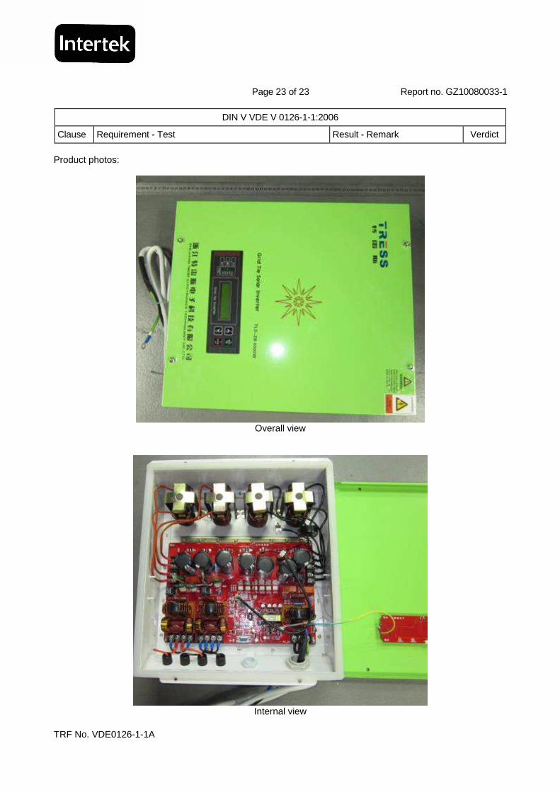
Product photos:
Overall view
Internal view