Tenant Design Criteria - Macerich...
28
Tenant Design Criteria Section t Technical Criteria Updated: October 2017 1961 Chain Bridge Road, Suite 105 Tysons Corner, VA 22102
Transcript of Tenant Design Criteria - Macerich...
Tenant Design CriteriaSection t Technical Criteria
Updated: October 2017
1961 Chain Bridge Road, Suite 105 Tysons Corner, VA 22102
Tenant Design Criteriat2
1961 Chain Bridge Road, Suite 105 Tysons Corner, VA 22102
Section t Technical CriteriaUpdated: October 2017 Addendum Log
ADDENDUM LOG
August, 2009 Full Update
September, 2011 Waterproof membrane requirement updated
May, 2012 Updated per TC
August, 2012 Updated Chilled Water Criteria (pg t12: Item 2); Updated Plumbing Criteria (pgs t19-t20)
November, 2012 Updated HVAC Systems Design (pg t10: Item G4)
May, 2013 Updated Roof Penetrations Criteria (pg t17)
September, 2013 Updated Water Meter content (t20)
March, 2014 Distribution of utilities through exit corridors is prohibited with exception (t21)
October, 2014 Update in Mechanical Zone 6 VAV Systems (pg t15- pg t16)
October, 2014 At grade level electrical conduit is not allowed to be installed in the slab (t5)
December, 2014 Wiring language updated (t5, #9)
January, 2015 Languageregardingthewaterproofingmembraneonpaget20 revised. (t20)
March, 2015 UpdatedPlumbingcontenttolistspecificlocationformainwater shut off valve to be at eye level. (t20)
March, 2016 Added Electric / Water Sub-meter Requirements (t4)
April, 2016 AddedWaterEfficiencylanguage(t21)
February, 2017 Added Equipment Controls, Fan Coil Unit Design and Variable Air Volume Box Design language
April, 2017 Removed language regarding Telephone Service (t5) Replaced with language regarding Communications Services (t5)
October, 2017 Added information regarding Commissioning Checklist as Exhibit A, page t25 Added information regarding Single Line Diagram as Exhibit B, page t26 Added information regarding Belimo Energy Valve - EV Series as Exhibit C, page t27 & t28
Tenant Design Criteriat3
1961 Chain Bridge Road, Suite 105 Tysons Corner, VA 22102
Section t Technical CriteriaUpdated: October 2017
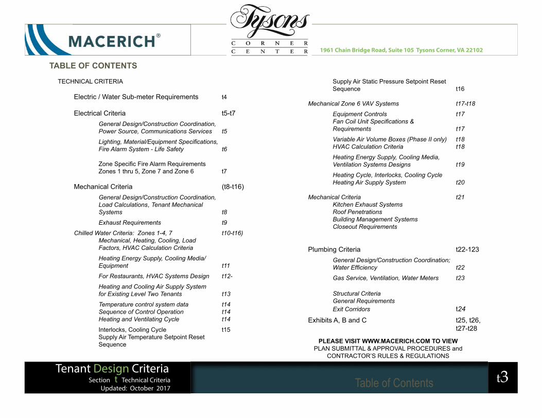
TECHNICAL CRITERIA
Electric / Water Sub-meter Requirements t4
Electrical Criteria t5-t7 General Design/Construction Coordination, Power Source, Communications Services t5
Lighting,Material/EquipmentSpecifications, Fire Alarm System - Life Safety t6
ZoneSpecificFireAlarmRequirements Zones 1 thru 5, Zone 7 and Zone 6 t7
Mechanical Criteria (t8-t16) General Design/Construction Coordination, Load Calculations , Tenant Mechanical Systems t8
Exhaust Requirements t9
Chilled Water Criteria: Zones 1-4, 7 t10-t16) Mechanical, Heating, Cooling, Load Factors, HVAC Calculation Criteria
Heating Energy Supply, Cooling Media/ Equipment t11
For Restaurants, HVAC Systems Design t12-
Heating and Cooling Air Supply System for Existing Level Two Tenants t13
Temperature control system data t14 Sequence of Control Operation t14 Heating and Ventilating Cycle t14
Interlocks, Cooling Cycle t15 Supply Air Temperature Setpoint Reset Sequence
Table of Contents
TABLE OF CONTENTS
PLEASE VISIT WWW.MACERICH.COM TO VIEWPLAN SUBMITTAL & APPROVAL PROCEDURES and
CONTRACTOR’S RULES & REGULATIONS
Supply Air Static Pressure Setpoint Reset Sequence t16 Mechanical Zone 6 VAV Systems t17-t18
Equipment Controls t17 FanCoilUnitSpecifications& Requirements t17
Variable Air Volume Boxes (Phase II only) t18 HVAC Calculation Criteria t18
Heating Energy Supply, Cooling Media, Ventilation Systems Designs t19
Heating Cycle, Interlocks, Cooling Cycle Heating Air Supply System t20
Mechanical Criteria t21 Kitchen Exhaust Systems Roof Penetrations Building Management Systems Closeout Requirements Plumbing Criteria t22-123 General Design/Construction Coordination; WaterEfficiency t22
Gas Service, Ventilation, Water Meters t23
Structural Criteria General Requirements Exit Corridors t24 Exhibits A, B and C t25, t26, t27-t28
Tenant Design Criteriat4
1961 Chain Bridge Road, Suite 105 Tysons Corner, VA 22102
Section t Technical CriteriaUpdated: October 2017
ELECTRIC / WATER SUB-METER REQUIREMENTS
As applicable for property, if there is an existing electric or water sub-meter in the Tenant’s space, then the Tenant must have the meter recommissioned to ensure proper installation and functionality. Alternatively, the Tenant can choosetoinstallanewmeterthatmeetsMacerich’smeterspecifications.Either option must be performed by a Landlord-approved electrician and verifiedbyMacerich,andwillbeattheTenant’ssolecost.
METER SPECSTenantmayinstallthemeterspecifiedbyMacerichorthelike.Metermustmeet the following criteria: Electric:
• Meters must be revenue grade.• There must be at least a 6-digit display.• Meter must be able to read demand (kW) and usage (kWh).• The meter must capture the electric usage of the entire Tenant space,
including HVAC units. If this is not possible, then it must be noted.• If using a meter with CTs, note if a multiplier is required and what the
multiplier is on the face of the meter.
Water:
• Metermustbeproperlysizedforthewaterflowinthespace.Generallythis means the size of the meter should match the size of the water line, or the meter can be 1/4” smaller than the line. This means that if there is a 1” water line servicing the space, a properly sized meter would be 3/4” or 1”.
Installation Requirements:
• Meters must be installed by a Landlord approved electrician.• InstallationmustbeverifiedandapprovedbytheOperationsManager,
or a member of the Operations staff, at the property.• Proof of inspection must be sent to the Energy Management Depart-
ment (Alaine Marx, [email protected]) and should include the following:
- Date of installation or recommissioning- Picture of the meter at time of installation or recommissioning. Picture should be clear and should display kWh and kW legibly.-Confirmationthatthemetercoverswholetenantspace.- Meter make and model- Units that the meter reads in- Multiplier, if applicable
Tenant Design CriteriaTechnical Criteria
1961 Chain Bridge Road, Suite 105 Tysons Corner, VA 22102
t5Section t Technical CriteriaUpdated: October 2017
General Design/Construction CoordinationThe electrical criteria is provided for the purpose of designing the Tenant’s electrical system. This criteria is provided as a guideline for Tenant’s Engineer. It is the Tenant’s responsibility to verify existing conditions and comply with all applicable codes and standards.
1. Conduitandracewayhangers,clamps,lightfixtures,junctionboxes,sup-ports,etc.mustbefastenedtojoistsand/orbeams.Donotattachdirectlyto the slab, roof deck, ductwork, piping or conduit above.
2. Tenant’sequipment in theMallelectric roommustbeclearly identifiedwith Tenant’s name and space number.
3. Provideaccesspanelsatalljunctionboxlocationsandatsmokedetec-tors above the ceiling.
4. Alloutletboxes,floorboxes,wireraceways,power/telephonepoles,plug-in molding, wiring devices, hanger supports and other items required for a complete distribution must be furnished and installed by Tenant.
5. Furnishand installpower toroof topunits,waterheater,storefixtures,signage,musicsystemsandanyotherfixturesorequipmentprovidedbyTenant. All cutting and patching must be provided by Tenant.
Complete Engineered drawings must be submitted to the Landlord’s Tenant Coordinator for review and approval. Landlord will review the plans for confor-mance to basic Mall requirements. The Landlord does not review for electrical design, nor does the Landlord accept responsibility for the Tenant’s adher-ence to governing codes.
The documents to be submitted for Landlord approval must include the following:1. Completeplansandspecificationsforallelectricalwork,includinglight-
ing, power and one line riser Diagram. Documents must be signed and sealed by a Licensed Engineer in the state where the Shopping Center is located.
2. Drawings must include panel schedules, load calculations and meter information, if applicable.
3. Structural drawings must be submitted for all equipment that will be sus-pended from the steel structure.
Power SourceAll work required to connect Tenant to the main power source must be per-formed by Tenant’s designated electrician, at Tenant’s expense. Exceptions to this requirement may be granted by the Tenant Coordinator.
Tenant is responsible for feeders to the Tenant space, installation of a dry type transformer, panels and complete distribution throughout the Tenant space.
Landlord will provide the main power source for Tenant’s connection. Power source will be 277/480v, 3 phase, 4 wire and will be available in the nearest Mall electric room. Tenants are responsible for re-use of, or connection to an existing disconnect switch in the mall electric room and must pull the feeder wires to the Tenant’s demised premises. If service from previous Tenant does not exist, Landlord will provide an empty 2” conduit with pull-wire from the mall electric room to the Tenant space. If a larger conduit or service is required, Tenant is responsible for installation of same from the power source to the demised premises.
Communications Services
1. Landlordhasinstalledahigh-speedfiberinfrastructureattheCenterforpurposes of providing voice and data access throughout the Center. All access for Tenant’s voice and data services must be sourced through Landlord’s designated provider which is currently Granite Telecommu-nications or such alternative provider as designated by Landlord. The vendor contact for voice and data services can be found in the Tenant Criteria Package under General Information.
2. Forallwiringneedsincommonelectricalrooms,arequiredvendormustbe used to maintain the integrity of the electrical room. The vendor con-tact for low voltage wiring needs can be found in the Tenant Criteria Pack-age under General Information.
ELECTRICAL CRITERIA
Tenant Design CriteriaTechnical Criteria
1961 Chain Bridge Road, Suite 105 Tysons Corner, VA 22102
t6Section t Technical CriteriaUpdated: October 2017
LightingProvidealightingscheduleforreviewinconjunctionwithareflectedceilingplan. Lighting must conform to the following guidelines:
1. Display window lighting must be controlled by a time clock and be on during the hours the Shopping Center is open. Display window lighting at the ceiling must be glare-free and at approved levels at the storefront glass line. The light source shall not be visible from the Mall concourse.
2. Recessed incandescent down lights may be used.
3. Exit, emergency and night lights must be provided throughout, as deter-mined by governing codes.
4. Fluorescent lighting in thesalesareamustbe recessedandmustusemetalparaboliclouvertypelenseswithaminimumof9cellconfigurationforastandard2’x2’fixture.Barelampfluorescentorfluorescentfixtureswith acrylic prismatic lenses may be used only in concealed areas or stock rooms.2’x4’fixturesarenotpermittedinsalesorcustomerareas.
5. Track lighting may be used if the track is painted to match the ceiling color.
Tenant is responsible for lighting system control, including connection to the BuildingManagement system and connection to the FireAlarm system, ifrequired. All emergency lighting, exit signs, horns and strobes must be pro-vided by Tenant as required by code.
Material/Equipment Specifications1. Drawingsmust includecompletematerialspecifications includingman-
ufacturer’s name and product number and complete schedules of all equipmentandfixturestobeinstalled.
2. All material and equipment must be new and of a commercial grade and must bear Underwriter’s labels where such labeling applies.
3. At grade level electrical conduit may be installed at least 4” under the slab and must be in Schedule 40 PVC conduit. But never allowed to be installed in the slab or less than 4” below slab.
4. Floorboxesmustbewatertight.
5. Pullboxesorjunctionboxesmustbeaminimumof12gaugegalvanizedsteel outlets. Boxes in walls must be galvanized pressed steel or case metal. Caulk around boxes to eliminate noise transmission.
6. All main and branch feeders and circuitry wiring must be copper. All con-ductors to have 600 volt insulation type THW, THWN or THHN.
7. Conveniencereceptaclesmustbespecificationgrade,120volt,20ampsand be grounding type per NEC.
8. Manual or magnetic starters, switches, contactors, relays, time switches, safety devices, dimmers and other controls must be commercial type with heavy duty ratings and must be installed in strict conformance with the manufacturer’s recommendation and applicable codes.
9. Any exposed low voltage wiring must be plenum graded.
10. All wiring of any type must be installed in conduit or must be armored cable (BX). Armored cable will only be allowed for concealed branch circuit wiring within the demised premises. Exposed and/or open wiring ofanykindwillnotbeallowed.Flexibleconduitsmustbeusedforcon-nections to vibrating equipment.
11. Trenching of the slab is not permitted without written permission from the Landlord. Tenant to provide all structural support needed if trenching is permitted,includingwrittencertificationtotheLandlordthatthetrenchinghas not affected the integrity or weight capacity of the slab.
Fire Alarm System - Life Safety1. Ifrequired,Tenantmustprovideacompletefirealarmdetectionsystem
within the Tenant space as an extension of the Landlord’s building-wide addressablefirealarmsystem.
2. Tenant is required to use Landlord’s designated contractor for installation or removal of the necessary smoke detectors and for connection to the mainfirealarmsystem.Systemmustcomplywiththerequirementsofthe governing authority.
3. All emergency lighting, exit signs, horns and strobes must be provided by Tenant as required by code.
**See next page for zone specific Tenant Fire Alarm requirements**
ELECTRICAL CRITERIA (Cont’d.)
Tenant Design CriteriaTechnical Criteria
1961 Chain Bridge Road, Suite 105 Tysons Corner, VA 22102
t7Section t Technical CriteriaUpdated: October 2017
Zone Specific Fire Alarm RequirementsThe following requirements do not replace individual Tenant code require-ments based on occupancy or use. This information is general in nature and allquestions,specifictothisTenant,shouldbedirectedtotheTenantCoor-dinator.
Zones 1 through 5:
Tenants within these zones are not required to install fire alarm systems,unless required by specific useor occupancy. IfTenantHVACunit is over2000CFM,Tenantwillberequiredtoinstallaductmountedsmokedetector,perIMCrequirements,connectedtotheMallfirealarmsystem.AconnectionpointisprovidedadjacenttotheTenantspaceintheservicecorridor.TheMallrequiredfirealarmcontractoristobeusedatTenantexpense.
Zone 7:
Tenantsinzone7arenotrequiredtoinstallfirealarmsystemsunlessrequiredbyspecificuseoroccupancy.IfTenantHVACunitisover2000CFM,Tenantwill be required to install a duct mounted smoke detector, per IMC require-ments.ThereisnoconnectiontotheMallfirealarmsysteminthiszone.
Zone 6:
This Tenant zone was previously required to have smoke evacuation and smoke detection systems within each of the Tenant spaces. Theses are no longer requirements.
Tenants in this zoneare required to removeall smokedetection/firealarmdevices, and associated wiring in the Tenant space prior to store opening. The MallrequiredfirealarmcontractoristobeusedatTenant’sexpenseforallfirealarm removals, permitting and re-programming of the Landlord system.
ELECTRICAL CRITERIA (Cont’d.)
Tenant Design CriteriaTechnical Criteria
1961 Chain Bridge Road, Suite 105 Tysons Corner, VA 22102
t8Section t Technical CriteriaUpdated: October 2017
General Design/Construction CoordinationThe mechanical criteria is provided for the purpose of designing the Tenant’s heating, ventilating and air conditioning system. This criteria is provided for Tenant’s Engineer. It is the Tenant’s responsibility to verify existing conditions and comply with all applicable codes and standards.
Complete Engineered drawings must be submitted to Landlord’s Tenant Coordinator for review and approval. Landlord will review the plans for conformance to basic Mall requirements as outlined in this criteria. Non-conformancewithcriteriawillbe immediatebasis forplan rejection.TenantEngineer shall submit completed checklist and load calculations in concurrence with plans submission. The Landlord does not review for mechanical design, nor does the Landlord accept responsibility for the Tenant’s adherence to governing codes.
Tenant space shall be delivered in an “as-is”, “where-is” condition, or as specifically noted in the Lease document. Tenant shall be responsible forrelocation or extension of mechanical services as required for their design. Additionally, all mechanical equipment associated wiring and piping not being re-used shall be completely removed and disposed of by this Tenant. Do NOT abandon in place.
The documents to be submitted for Landlord approval must include the following:1. Complete plans and specifications covering the heating, ventilating
and air conditioning system. Show make, type and performance of all equipment. Documents must be signed and sealed by a Licensed Engineer in the state where the Shopping Center is located. Utilization of equipment schedules similar to those provided in this criteria manual is strongly recommended.
2. Calculations showing the heating and cooling required, including transmission and ventilation losses in the space and heating and cooling provided.Fortheventilationsupplyandexhaustrequiredforthespace.Calculations shall be as described in “Load Calculations” included below.
3. Temperature control system data showing make, control and energy management systems.
4. ExhaustsystemlayoutincludingCFMandequipmentspecifications.
5. Structural details for support of all roof top equipment and equipment suspended from the steel structure.
6. A chilled water piping diagram, if applicable. All chilled water AHU’s that utilize outside airside economizer shall have coil freeze protection provided.
Load CalculationsThe Tenant must perform all calculations in accordance with methods set forth in the latest American Society of Heating, Refrigeration and Air Conditioning Engineers’ Guide and Data Book and in accordance with good engineering practice.Allcalculationsmustbetabulatedinaconcise,orderlymanner.Formultiple zone tenants, the outside air calculation spreadsheet provided in this criteriamaybeutilizedtocomplywithFairfaxCountyPermitOffice.
Tenant Mechanical Systems: The type of Tenant mechanical system required will be determined by the Mall zone the Tenant space is located in. Generally, zone 1, 2, 3, 4 and 7 spaces are chilled water systems, zone 6 spaces are on a shared VAV system and zone 5 spaces are on individual rooftop unit systems. There may be exceptionstotheseconditions.FieldverificationbytheTenantisrequiredtodetermineactualfieldconditions.PleaseconsulttheTenantCoordinatorwithspecificquestions.
Themechanicaldesigncriteriaonpagest8andt16ofthissectionarespecificto the various zones in the Center. Please refer to the zone maps on pages gi9 and gi10 of the General Information section to identify the zone a Tenant space is located in. Tenant engineer shall design and submit plans as required inthezonespecificcriteria.
The Tenant is required to submit calculations indicating the heating and cooling loads for the space and calculations for exhaust and make-up air.
Tenants must design for a maximum noise criteria of NC40 for all spaces except kitchens and other similar work areas.
MECHANICAL CRITERIA
Tenant Design CriteriaTechnical Criteria
1961 Chain Bridge Road, Suite 105 Tysons Corner, VA 22102
t9Section t Technical CriteriaUpdated: October 2017
MECHANICAL CRITERIA (cont’d.)
Exhaust RequirementsTenantswhoseoperationproducesobjectionableodorssuchasrestaurants,pet shops, hair salons, nail salons and the like must maintain 10% negative air pressure with respect to the Mall by providing make-up air equal to 90% exhaust air volume. Tenant may be required to provide, at Landlord’s discretion, a separate make-up outside air supply system to balance Tenant’s exhaust system. Spaces that require exhaust must be designed to provide negativeairpressurerelativetoadjoiningconditionedspacestopreventodor
Tenant Design CriteriaTechnical Criteria
1961 Chain Bridge Road, Suite 105 Tysons Corner, VA 22102
t10Section t Technical CriteriaUpdated: October 2017
CHILLED WATER CRITERIA: ZONES 1-4, 7
MECHANICAL:
1. General: The Tenant provided HVAC system shall be VAV in nature for spaces with multiple zones and/or above approximately 3000 square feet, AHU’s/Mechanical equipment shall be equipped with a full airside economizer system whensufficientoutsideairandreliefisavailable.Singlezoneandlessthan3000square feet - constant volume AHU’s are allowed with full airside economizer. VAV AHU’s shall utilize variable speed drives for the supply and return/relief fans. Control system shall utilize a BacNet compatible/compliant Direct Digital Control system that incorporates reset strategies for the static pressure setpoint and the supply air temperature setpoint (applicable to VAV), based on the loads being served by the AHU.
2. Air Handler Requirements (following information should be provided on the designdrawingspecifications):
1. Provide AHU submittal(s) to landlord for review. All chilled water AHU submittals must be submitted to landlord and approved by landlord prior to unit being ordered.
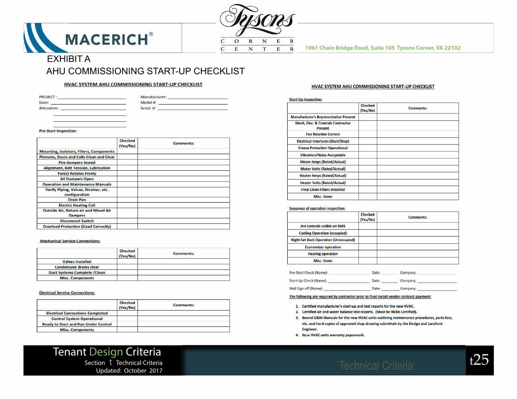
2. Commissioning of all AHU’s are required once installed and opera-tional. Contractor is responsible for coordinating start-up and com-missioning with landlord representatives. Contractor shall provide landlordaminimumoffive(5)daysnotice.(Example Commissioning Checklist PDF attached as Exhibit A, page t25)
3. Design Engineer shall note on drawing that the controls submittal shall be provided to landlord for review prior to installation.
4. Contractor is responsible for providing controls submittal to landlord for review and approval to verify compatibility with building system. Submit documents on all control product components prior to installa-tion.
5. Contractor shall submit to landlord control point list prior to installa-tion.
6. Contractor shall submit BACNET conformance compliance statement to landlord prior to installation.
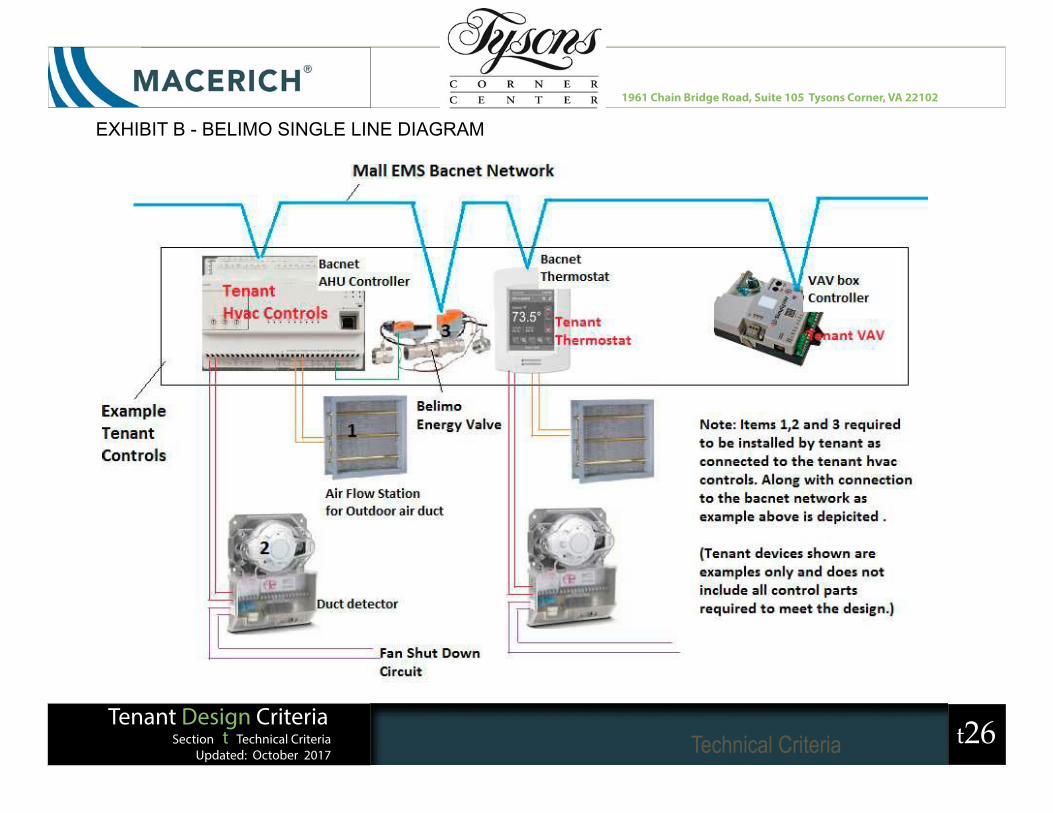
7. See single line diagram in criteria for example of mall’s control sequence. (Example PDF attached as Exhibit B, page t26)
8. Thefollowingarerequiredfromthecontractorpriortofinalvendorcontract payment:
a. Certifiedmanufacturer’sstart-upandtestreportforallnewHVACunits.b. Certifiedairandwaterbalancingtestreports.c. Bound O&M manuals for all new HVAC units outlining maintenance
procedures, parts list, etc. and hard copies of approved shop drawing submittals.
d. New HVAC units warranty paperwork.
3. This design criteria is intended to guide the Tenant HVAC designer toward the use of a VAV system utilizing variable speed drive based blow through air handling units equipped with full airside economizers, and either return or exhaust/relief fans. Direct drive plug fans are desired but not mandated. Very low face velocity cooling coils are mandated to allow the use of high chilled water supplyandreturntemperaturestoimprovethechillerplantsystemefficiency,andto reduce airside pressure drops and fan energy waste to maximize chilled water economizer operation.
4. Design Conditions: Tenant’s heating and cooling system design shall be based upon the following conditions:
A. HEATING1. Insidedrybulbtemperature:Sales72°FStorage70°F2. Outsidedrybulbtemperature:10°F3. Average wind velocity: 7 mph4. When the space is not occupied, minimum temperature shall at no time gobelow55°FandonlyrecirculatedairmaybeusedbyTenantprovided
unit heater.
B. COOLING1. Insidedrybulbtemperature,salesandstorage:72°F2. Relative humidity (maximum): 50%3. Outsidedrybulb:93°F4. Outsidewetbulb:78°F
C. LOAD FACTORS:1. Roof U-Value: 0.0842. Wall U-Value: 0.3003. Lighting Density-per Lease Outline Drawing (maximum 3.0 watts per squarefootofsalesfloororcustomeraccessibleareasunlessapprovedby
Tenant Design CriteriaTechnical Criteria
1961 Chain Bridge Road, Suite 105 Tysons Corner, VA 22102
t11Section t Technical CriteriaUpdated: October 2017
Landlord,maximumof1.5W/SFforbackofhouseoperations).Coolingloadsassociatedwithlightingdensitiesgreaterthan3.0W/SFand1.5W/SFshallbecooledbyseparatetenantprovidedDXsplitsystems,poweredfrom the tenant meter. 5. Population Density - 1 person per 50 sq. ft. of demised space shall
be used when developing the cooling calculations and for fresh air requirements. Sensible heat shall be based on 315 BTUH/person, Latent heat shall be based on 325 BTUH/person. The square footage to be used for this calculation consists of the entire demised area, not justthecustomeraccessibleareas.
D. HVAC CALCULATION CRITERIA:1. General: All calculations shall be in accordance with all the latest editionoftheASHRAEFundamentalsGuideandDataBook,applicablecodes and requirements and good engineering practice. All calculations shallbeupontheincludedform,certifiedbyaregisteredprofessionalengi-neerand,submittedforLandlord’sengineers’approvalwithfinalworkingdrawings.2. Aminimumof20CFMoffreshoutsideairperperson,basedontheoccupancy calculated in section 3.C.4 above, (one person per 50 square feetofdemisedspace)orthecodemandatedOSACFM,whicheverisgreater, shall be used when developing the heating and cooling calcula-tions. Outside code calculation spreadsheet similar to that provided (if requested) shall be provided on plans for satisfactory permit review.3. Heating Load: Space shall be calculated to maintain the minimum space temperatures indicated with the equipment for day heating loads. However, no credit may be taken for lighting and people.4. Cooling Load: Cooling load calculations (lights, equipment and occu-pants) shall take into account all interior heat producing items, as well as the loads imposed by the fresh air component and the walls, windows, skylightsetc.Forspacesutilizingfullairsideeconomizer,loadsexceed-ing40.0BTUperhourpersquarefoot(300SF/Ton)shallbecooledbyseparate tenant provided supplemental split system AC unit, powered from thetenantmeter,unlessapprovedinadvancebytheLandlord.Forecono-mizer limited tenants, loads exceeding 31.1 BTU per hour per square foot (385SF/Ton)shallbecooledbyaseparatetenantprovidedsupplementalsplit system AC unit.
5. ThepeakdesignCFMfortheAHUshallbebasedoneitherthedesignsupplyairtemperaturefortheunitonthepeakloadday,or63°Fsupply air temperature based on the peak loads in existence when the OSAtemperatureis60°F,whicheverishigher.6. Scope: Tenant shall submit to Landlord calculations for the following:
a. Peakcoolingload,andcoolingloadat60°Fambientwithfulloccu-pancy and equipment loads.b. Peak heating loadc. Instantaneous cooling load for each space served by an individual terminal unit if more than one is required.d. CirculatedCFMrequiredforpeakcoolingload,using55°Fsupplyairtemperature,andac63°Fsupplyairtemperature.e. Instantaneous heating load for each heated space.f. Toilet room exhaust air calculation, including static pressure.g. Static pressures on the low pressure duct system connected to the VAV terminal.h. Exhaust quantities and static pressure for kitchen for kitchen exhaust.i. Tenant VAV system shall be designed to provide no less than 1.75 CFMperdemisedS.F.
E. HEATING ENERGY SUPPLY7. Heating energy supply will be electric and Tenant will make available from Tenant’s electric service to power Tenant provided unit heaters.
F. COOLING MEDIA/EQUIPMENT:1. ForthepurposesofsizingandselectingtheAHUandcoolingcoils,the temperature of the chilled water supply provided by landlord, if applicable,shallnotbelessthan50degreesFahrenheitEWTandthetemperature of the chilled water return provided back to the system by the tenantAHUshallnotbelessthan64degreesFahrenheit.2. If Tenant uses chilled water service it shall be made available during normal “business hours” whenever outdoor temperature is equal to or above60degreesFahrenheit.Thetemperaturewillbevariedbasedonthe cooling loads being served by the chiller plant, and may be higher or lower than described in this Design Criteria at any given time of day or time of the year.
CHILLED WATER CRITERIA: ZONES 1-4, 7 (cont’d.)
Tenant Design CriteriaTechnical Criteria
1961 Chain Bridge Road, Suite 105 Tysons Corner, VA 22102
t12Section t Technical CriteriaUpdated: October 2017
3. Minimum working pressure of all Tenants’ chilled water equipment will be 125 PSIG. 4. Maximum allowable pressure drop through all Tenant’s chilled water piping and equipment (measured at connecting points to main) shallbefifteenfeet(15’-0”)WaterGauge(WG)atthe14degreetempera-ture differential described above.5. The cooling coil shall be 5/8” minimum tube diameter, copper with a 0.28”wallthicknessminimum.Thefinthicknessshallbe0.008”minimum.6. The maximum distance between cooling coil drain pans that pass 100%ofthewaythruthecoilfinnedsurfacearea,shallbe24”.Ifthecooling coils are taller than 24”, provide intermediate drain pans to limit the vertical distance between drain pans to 24” maximum.7. The cooling coil drain pans and cooling coil casings shall be 304 stainless steel, of adequate thickness to provide the intended duty, and double sloped to encourage water drainage from the drain pans. The drain pans shall drain dry within 15 minutes of the air handling unit being shut down.
For Tenant’s with limited/partial airside economizer capability1. Tenant to provide a fresh air delivery system that will deliver a mini-mumof20CFMperpersonoffreshairata50squarefootperpersonoccupancy rate. The tenant shall be responsible for installing an econo-mizer system (fresh air intake duct and return fan system with exhaust ducting) that will utilize the greatest economically feasible amount of fresh air possible.2. The cooling coils in the air handling units, the AHU fan system and the distribution ductwork must all be increased in size to meet the tenant calculated peak winter cooling loads when the chiller plant is delivering 60degreeFchilledwatertemperaturesandtheambientconditionsare60degreeForless.TheloadbeingservedbytheAHUsystemshallbereduced by the amount of load that can be served with the design volume offreshairata63degreeFsupplyairtemperaturefromtheeconomizersystem.3. Thechillerplantsystemwillbeprovidingflowtotheloadsatanexpectedchilledwatertemperaturedifferentialof10degreeF,sothedesignchilledwaterreturntemperatureshallbe70degreeF.
4. Since the supply air temperature will be higher than would be deliv-ered in the summer, the supply air volume shall be increased to accommo-date the peak loads when using the higher AHU supply air temperatures.5. The AHU’s shall be blow thru in design, to reduce the supply air temperature as far as possible, while increasing the chilled water return temperature.
For Restaurants1. There is no requirement for full airside economizer. The tenant will havetoprovideafreshairdeliverythatwilldeliver20CFMperpersonoffresh air at a 50 square foot per person occupancy rate.2. The cooling coils in the air handling units, the AHU fan system and the distribution ductwork must all be increased in size to meet the tenant calculated peak winter cooling loads when the chiller plant is delivering 60degreeFchilledwatertemperaturesandtheambientconditionsare60degreeForless.TheloadbeingservedbytheAHUsystemshallbereduced by the amount of load that can be served with the design volume offreshairata63degreeFsupplyairtemperaturefromtheeconomizersystem.3. Thechillerplantsystemwillbeprovidingflowtotheloadsatanexpectedchilledwatertemperaturedifferentialof10degreeF,sothedesignchilledwaterreturntemperatureshallbe70degreeF.4. Since the supply air temperature will be higher than would be deliv-ered in the summer, the supply air volume shall be increased to accommo-date the peak loads when using the higher AHU supply air temperatures.5. The AHU’s shall be blow thru in design, to reduce the supply air temperature as far as possible, while increasing the chilled water return temperature.
G. HVAC SYSTEMS DESIGN:1. All Tenant HVAC systems must utilize computerized Direct Digital Controls that are native BacNet compatible/compliant. No pneumatic or electric/electronic controls are permitted. 2. Maximum outside air supply and re-circulated shall be equal to one hundredpercent(100%)ofCFMcirculated–afullairsideeconomizerisrequired.
CHILLED WATER CRITERIA: ZONES 1-4, 7 (cont’d.)
Tenant Design CriteriaTechnical Criteria
1961 Chain Bridge Road, Suite 105 Tysons Corner, VA 22102
t13Section t Technical CriteriaUpdated: October 2017
3. Minimum outside air supply shall be based on the higher of either (20 CFMperperson,calculatedatonepersonper50squarefeetofdemisedspace, or the minimum required by applicable codes), plus any additional requirements to maintain air supply equal to total air exhausted. This shallnotexceedtwentyfivepercent(25%)oftotalairvolumesupplied.The Tenant’s air handling system must be designed to operate under all conditions,withouttheneedtorelieveairintoortakeairfromtheadjacentenclosed mall.4. Freshairdampers,exhaustfandischargedampersandreliefairdampers shall be low leakage, opposed blade type. Maximum open area facevelocityofthevariousdampersystemsshallnotexceed800FPM.Relief/exhaust/return fan with vfd or barometric relief damper/hood shall be provided for 100% outside air economizer mode.5. Air pressure drop in ductwork shall not exceed 0.075 inches H2O per 100 ft. of straight run. The maximum air velocity in the main duct runs shallnotexceed1,500FPM,andthemaximumairvelocityintheductrun-outstothediffusersshallbe500FPM.Ducttap-offsshallbemadeata45degreeangleinthedirectionofairflow.Allbranchesandtake-offsshall be equipped with volume controlling devices. All ductwork shall be designed, provided, and installed in accordance with the latest methods use in ASHRAE Guide and the SMACNA Standards. 6. Motors shall be designed for variable speed inverter duty (applicable toVAVAHUonly)andberatedaspremiumefficiencybasedoncon-tinuous duty NEMA Standards. Motors rated ½ HP and larger shall be 3-phase, 480 volts, motors rated less than ½ HP shall be single-phase, 120 volts.7. Blower motors and other equipment vibrating shall be isolated from unit casing and from construction with vibration absorbing mountings.8. Ceiling diffusers shall be provided with volume control. 9. Level One Tenants will need special Landlord permission for shafts or venting through Level Two spaces
Heating and Cooling Air Supply System for Existing Level Two Tenants:
a. Chilled water cooling coil, as part of air handling unit described, with the following characteristics:
1. Enteringminimumwatertemperature:50degreesF.2. Watertemperatureriseacrosscoil:14degreesF.3. Minimumnumberofrows:8rows.Finperinchcount:12FPI,nomore,noless.Coilthicknessminimumis0.028”,finthicknessminimumis 0.008” minimum.4. Maximum air pressure drop through coil: 0.70 in WC5. Maximumairfacevelocityacrosscoilfinnedsurfacearea:300FPMfordrawthroughcoolingcoilconfigurations,350FPMforblowthroughcoolingcoilconfigurations.6. Maximum water pressure drop through coil (including valves, devices, and connected piping: 15 ft.
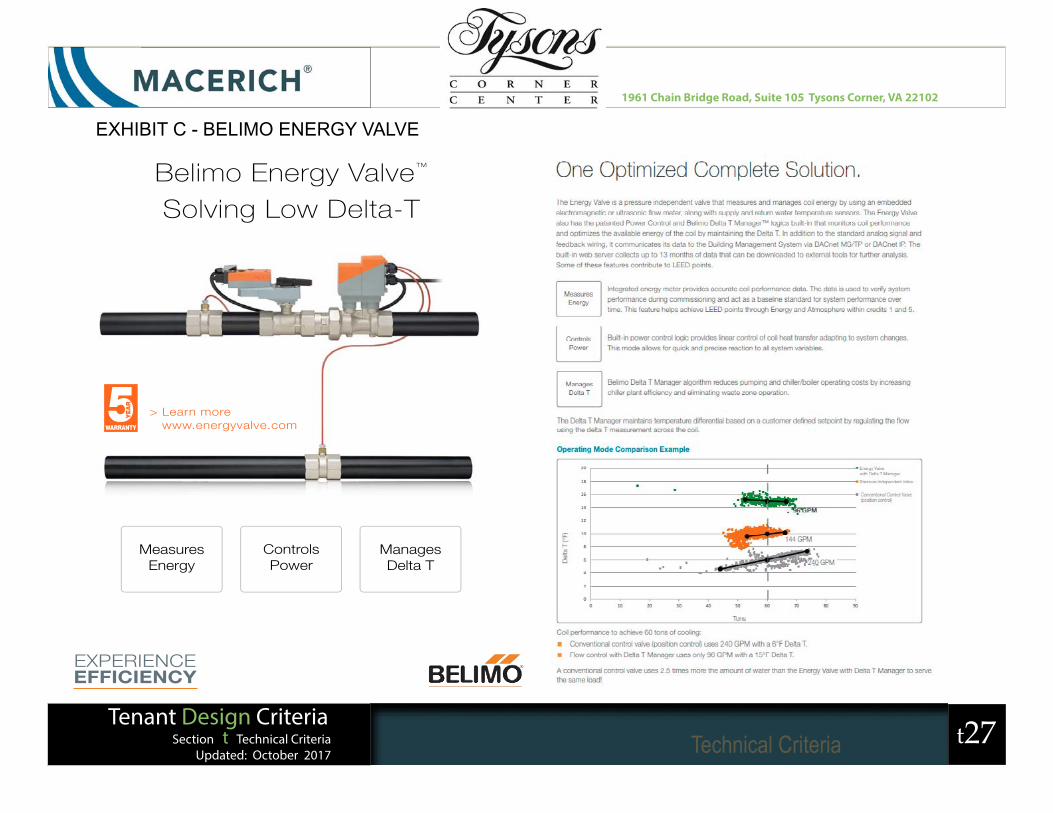
a. BacNet room thermostat governed full modulating two-way throt-tling type control valve. Belimo Energy Valve - EV Series. (See example attached as Exhibit C) Provide with inlet strainer, balancing valve on chilled water circuit of coil, manual and automatic air vents pipedtofloorsinks,freezestats,firestats,onehundredpercent(100%)O.A. Economizer, BacNet compliant DDC controls system as described elsewhere,returnorrelief/exhaustfan,airflowswitchesandhighlimitsafety cut out for electric coils.b. Electric resistance type heating coil(s) installed in Tenant provided unit heaters shall not exceed 7.5 KW per step and be thermostatically controlled by the DDC system supply air temperature setpoint. The heating system control signal shall be 0% to 100% heating unit output basedonthespacetemperaturebeingbetween-1.5°Fand-5°Fofthespace temperature setpoint. c. All supply duct work and chilled water piping shall be insulated oneinch(1”)andcondensatelinesone-halfinch(1/2”)withglassfiberwith non-combustible UL rated vapor barrier.d. Tenant shall submit the following information where applicable, for approval and acceptance in writing, before ordering any work to com-mence.e. Heating coil data showing.
1. Make, type and capacity.2. Coil width, length and power requirements and number of circuits.3. CFMhandledbycoilandcoilfacevelocity(ft/min).4. Entering and leaving air temperatures. BTU provided by air.
CHILLED WATER CRITERIA: ZONES 1-4, 7 (cont’d.)
Tenant Design CriteriaTechnical Criteria
1961 Chain Bridge Road, Suite 105 Tysons Corner, VA 22102
t14Section t Technical CriteriaUpdated: October 2017
5. Air pressure drop through coils (inches of water).
f. Cooling coil showing:
1. Make, type and cooling capacity, blow-thru or draw-thru.2. Header width, length and number of circuits.3. CFMhandledbycoilandcoilfacevelocity(ft/min).4. Entering and leaving air dry and wet bulb, dew point and entering and leaving water temperatures and total heat of entering and leaving air.5. GPM of water used and coil water velocity (ft/min).6. Water pressure drop through coil (ft. of water).7. Airpressuredropthroughcoil(WG–inchesofwater).8. Water pressure drop through the cooling system from the POC’s at the entry to the demised space, through all of the Tenant equipment and back to the POC.9. Coil thickness
10.Finthickness
g. Supply fan data:
1. Make and type.2. Airdelivery.CFMusing63°FsupplyairtemperatureandCFMusing55°Fsupplyairtemperature,andCFMpersquarefootofdemisedspace at these two conditions.3. Static pressure developed, static pressure required with 1” pressure dropacrossadirtyairfilterbank.4. MotorRPMandHPusing63°FsupplyairtemperatureandmotorRPMandHPusing55°Fsupplyairtemperature.FanRPMatthesetwo conditions.5. Type,sizeandcapacityofairfilters.6. Voltage, Amps, KW.
h. Unit heater data:
1. Make, type and size (motor HP and RPM for unit heaters).2. BTU/Hr. rating.3. EnteringandleavingairtemperaturesCFMcirculated.4. Voltage, Amps, kW per stage and total kW.
i. Temperature control system data:
1. General: Monitoring points shall be made available to the Landlord
systemforthepurposesofimprovingoverallsystemenergyefficiencyand also tenant comfort. These points shall be BacNet compatible controls available from each cooling or heating unit to connect to the Landlord system:• Supply air temperature setpoint.• Actual supply air temperature• Chilled water valve position command (0% to 100%)• Static pressure setpoint• Actual supply air static pressure• Thermostat setpoint (for each thermostat)• Actual temperature at each thermostat• Return air temperature• Mixed air temperature• Supply fan kW (from Variable Speed Drive or kW transducer)• Return/Relief/Exhaust fan kW (from Variable Speed Drive or kW transducer)• AHU status (on-off)• Supply fan speed• Return/relief/exhaust fan speed• Unit heater status (on-off)• Smoke Detector Monitor Input• Unit heater total kW draw (analog signal)
2. Provide the BacNet interface hardware and software required to send this information to the Landlord DDC system. The Landlord will provide the cable and hardware necessary to receive this informa-tion. Provide technical assistance from your DDC system provider to facilitate this interface. Provide IP connection in Tenant control panel for future mall connection for monitoring.3. Make and control diagram and description, and equipment submit-tals
j. Sequence of Control Operation:
1. Seasonalselectionshallbebyfullyautomatic“Summer–Winter”switch based on outside air temperature.2. These are generic sequences, the Tenant HVAC Design Engineer shall develop sequences that follow these basic guidelines and reset strategies,adaptedforthespecificneedsoftheindividualtenant.
CHILLED WATER CRITERIA: ZONES 1-4, 7 (cont’d.)
Tenant Design CriteriaTechnical Criteria
1961 Chain Bridge Road, Suite 105 Tysons Corner, VA 22102
t15Section t Technical CriteriaUpdated: October 2017
k. Heating and ventilating cycle:
• Daycycle(9am–10p.m.)ondaystheDemisedPremisesisopen for business.
a. BacNet compatible/compliant DDC control system shall energize the supply fan (the fan shall run continuously during the day cycle, utilizing the variable speed drive to maintain the static pressure set-point) and the electric heating coil. If a separate unit heater is utilized, the BacNet DDC system shall also have control of that equipment. Controller of electric heating coil will gradually turn on all circuits. The BacNet compatible/compliant DDC control system shall also energize the outside air, return air and relief air damper motors and place them under the control of the daytime space thermostat setpoint.b. As space temperature increases and approaches the space ther-mostat setting, the heating coil multi-step controller shall modulate toward the “off” position. When the space temperature has reached 1.5°Fbelowthesetpointofthethermostatthecontrollershallhavemodulated the heating coils to “off”.c. The outside air damper shall remain closed until the space tem-perature approaches the modulating range of the day time space thermostat setpoint at which time a set of contacts controlled by the DDC system shall energize a minimum positioning switch to open the outside air damper to minimum position. An auxiliary switch mounted on the outside air damper motor shall modulate the relief air damper motor open as required. When heating coil control is in the “off” position (coil de-energized) and on a further rise in a room temperature, the economizer control system is enabled and the relief dampers open and return air damper closed to maintain temperature. The return/exhaust/relief fan speed shall be controlled to maintain the relative pressure between the Tenant space and the mall space as describedelsewhere.TheFreezestatshalloverrideentiresystem.Ifthemixedairtemperaturedropsbelow45°F,anaudibleandvisualalarm will be sent to the tenants from their DDC system, and the chilled water valve will be opened to the 100% open position. The return/relief/exhaust fan shall be shut down, the relief and fresh air dampers shall be commanded closed and the supply fan shall be shut down.
d. Whentemperatureincreasesabove48°F,thereverseshalloccur.e. Low limit controller located in the discharge air shall override the BacNet space thermostat control logic to maintain a minimum dis-charge air temperature.
• Night Cycle
a. BacNet compatible/compliant DDC control system shall de-energize the fan circuit and damper motors and place fan operation under the control of the night space thermostat setpoint. The DDC system shall operate the fan intermittently to maintain space temperature. Outside and relief air dampers shall be closed and return air damper open; electric coil shall be operating as in daytime.
1. Interlocks
a. Interlock will keep electric coil(s) de-energized whenever respec-tive supply fan is not running.
b. Whenever electric coil is de-energized, controller shall return to “off” position. The electric coils shall always start unloaded.
c. Chilled water coil control valve shall be closed whenever the heatingcoilsystemisinoperation,exceptasdescribedbyFreez-stat logic.
2. Cooling Cycle
• Day Cycle
a. BacNet compatible/compliant DDC control system shall energize the supply fan (the fan shall run continuously during the day cycle) and shall energize the minimum positioning switch of the outside air damper opening same to the minimum position. The econo-mizersystemshallbeenablediftheoutsideairtemperatureis10°F(adjustable)lowerthanthereturnairtemperature.b.TheDDCsystemshallvarychilledwaterflowratebymeansofmodulating the control valve of the cooling coil to maintain the AHU supply air temperature setpoint. The AHU supply air temperature setpoint shall be reset based on the offset of the space tempera-ture from the space temperature setpoint as described below. The space temperature shall be compared to the space temperature
CHILLED WATER CRITERIA: ZONES 1-4, 7 (cont’d.)
Tenant Design CriteriaTechnical Criteria
1961 Chain Bridge Road, Suite 105 Tysons Corner, VA 22102
t16Section t Technical CriteriaUpdated: October 2017
setpoint in control at the zone thermostat. If the space temperature is above or below the setpoint as described below, the supply air temperature setpoint and the static pressure setpoint for the AHU shall be gradually decreased or increased in a proportional manner, each minute, as described next:
1. Supply Air Temperature Setpoint Reset Sequence
• Ifthespacetemperatureisbetween-0.5°Fbelowthespacetempera-turesetpointand3.5°Fabovethespacetemperaturesetpointandthespace temperature is increasing, proportionally decrease the supply air temperature setpoint that controls the cooling coil control valve by 0.02°F(adjustable)to0.15°F(adjustable)eachminutethattheunitisin operation. • Ifthespacetemperatureismorethan1.5°Fabovethespacetem-perature setpoint whether or not the space temperature is increasing, decrease the supply air temperature setpoint that controls the cooling coilcontrolvalveby0.12°F(adjustable)eachminutethattheunitisinoperation, in addition to the reset described above. A minimum supply airtemperaturesetpointof55°Fshallbeutilized.• Ifthespacetemperatureisbetween+0.5°Fabovethespacetem-peraturesetpointand-3.5°Fbelowthespacetemperaturesetpoint,and the space temperature is decreasing, proportionally increase the supply air temperature setpoint that controls the cooling coil control valveby0.008°F(adjustable)to0.10°F(adjustable)eachminutethatthe unit is in operation.• Ifthespacetemperatureismorethan0.75°Fbelowthespacetem-perature setpoint whether or not the space temperature is decreasing, increase the supply air temperature setpoint that controls the cooling coilcontrolvalveby0.08°F(adjustable)eachminutethattheunitisinoperation, in addition to the reset described above. A maximum supply airtemperaturesetpointof72°Fshallbeutilized.• The supply air temperature setpoint shall be started when the AHU starts based on a proportional reset: if the space temperature offset fromsetpointisbetween-2°Fand+2°F,starttheAHUwiththesupplyairtemperaturesetpointbetween72°Fand55°F.Runwiththisset-point for a 10 minute period, then release the setpoint to the automatic reset routines.
2. Supply Air Static Pressure Setpoint Reset Sequence
• Ifthespacetemperatureisbetween-0.5°Fbelowthespacetempera-turesetpointand3.5°Fabovethespacetemperaturesetpoint,andthespace temperature is increasing, proportionally increase the supply fan static pressure setpoint that controls the variable speed drive for the supplyfanby0.01inchesWC(adjustable)to0.125inchesWC(adjust-able) each minute that the unit is in operation. • Ifthespacetemperatureismorethan1.25°Fabovethespacetemperature setpoint whether or not the space temperature is increas-ing, increase the supply fan static pressure setpoint that controls the variablespeeddriveforthesupplyfanby0.08inchesWC(adjust-able) each minute that the unit is in operation, in addition to the reset described above. A maximum supply air static pressure setpoint of 1.50 inches WC, as measured at 10’ from the discharge of the AHU shall be utilized.• Ifthespacetemperatureisbetween+1.5°Fabovethespacetemper-aturesetpointand-3.5°Fbelowthespacetemperaturesetpoint,andthe space temperature is decreasing, decrease the supply fan static pressure setpoint that controls the variable speed drive for the supply fanby0.005inchesWC(adjustable)to0.025inchesWC(adjustable)each minute that the unit is in operation. • Ifthespacetemperatureismorethan-0.75°Fbelowthespacetemperature setpoint whether or not the space temperature is decreas-ing, decrease the supply fan static pressure setpoint that controls the variablespeeddriveforthesupplyfanby0.008inchesWC(adjust-able) each minute that the unit is in operation, in addition to the reset described above. A minimum supply air static pressure setpoint of 0.45 inches WC, as measured at 10’ from the discharge of the AHU shall be utilized.• If the heating system is enabled, set the static pressure setpoint to 1.5” WC and disable the static pressure resets. At fan startup, the initial static pressure setpoint shall be 1.5” WC. The resets shall be enabled once the fan has been enabled without the heating system being enabled for 10 minutes.
• Night cycle
MECHANICAL ZONE 6 VAV SYSTEMS
Tenant Design CriteriaTechnical Criteria
1961 Chain Bridge Road, Suite 105 Tysons Corner, VA 22102
t17Section t Technical CriteriaUpdated: October 2017
a. This BacNet compatible/compliant DDC control system shall de-energize all systems.
3. Heating and Cooling Air Supply System for Level One and New Con-struction Tenants: Refer to Design Criteria set forth above in Section C, on page t8. Heating and Cooling Air Supply System for Existing Level Two Tenants with the following exceptions
a. Total pressure drop of the low velocity system shall not exceed 0.25 inches. b. HeatingrequirementsofF-Setexteriorwalllosses(Tenantwithwallsadjacenttotheexteriorofthebuilding)orrooflosses (Tenants onthesecondfloor)shallbeinstalledbyTenant.Heatingequipmentshallbesizedtomaintain72°Finthespace,withanoutdoortempera-tureof10°F.Theheatingshallbeaccomplishedbymeansotherthana re-heat system on the VAV cooling system. Heating coil shall be 480volt,3phase,3wireandshallbeequippedwithaflowswitchtopreventthecoilfrombeingenergizedwithoutpositiveairflow.
1. Design Conditions: Tenant’s heating and cooling system design shall be based upon the following conditions:
A. Heating:1. Insidedrybulbtemperature:Sales72°F;Storage70°F.2. Outsidedrybulbtemperature:10°F.3. Average wind velocity: 7 mph4. When the space is not occupied, minimum temperature shall at no timegobelow55°Fandonlyre-circulatedairmaybeused.
B. Cooling:1. Insidedrybulbtemperature:72°F.2. Relative humidity (maximum): 50%.3. Outsidedrybulb:93°F.4. Outsidewetbulb:78°F.
C. Load Factors:1. Roof U-Value: 0.084.2. Wall U-Value: 0.300.3. Lighting Density- per Lease Outline Drawing (maximum 3.0 watts per squarefootofsalesfloororcustomeraccessibleareasunlessapproved
by Landlord, maximum of 1.5 watts per square foot for back of house operations). Cooling loads associated with lighting densities greater than 3.0 watts per square foot and 1.5 watts per square foot shall be cooled by separate Tenant provided DX split systems, powered from the Tenant electric panel.4. Population Density- 1 person per 50 square feet of demised space shall be used when developing the cooling calculations. Sensible heat shall be based on 315 BTUH/person. Latent heat shall be based on 325 BTUH/person. The square footage to be used for this calculation consists oftheentiredemisedarea,notjustthecustomeraccessibleareas.
D. EQUIPMENT CONTROLS:All HVAC energy management controls shall be purchased through and installed by Landlord’s required controls contractor at Tenant’s expense. Tenant shall contract directly with Landlord’s required controls contractor to install a fully functional direct digital control (DDC) system that must be interfaced into the Landlord’s building automation system (BAS). These controls shall provide the following data at a minimum:
Space TemperatureSupply Air TemperatureReturn Air TemperatureFanStatus(BinaryCurrentTransducer)Chilled water Valve PositionFanStart/Stop
Tenant shall purchase a new chilled water valve from Landlord’s control contractor at Tenant’s expense. Automated chilled water valves are to be installed by Tenant’s mechanical contractor and wired by Landlord’s control contractor at Tenant’s expense. Tenant is not allowed access to the Landlord’s BAS. If a Tenant desires to monitor space conditions, then Tenant is allowed to install, at their expense a stand-alone BAS to monitor conditions within their space if desired. Any stand-alone monitoring system shall not be attached to the Landlord’s BAS in any way.
Tenant shall contract directly with the Landlord’s required controls contractor to remove all DDC components and disconnect all network cabling before demolition.
MECHANICAL ZONE 6 VAV SYSTEMS (cont’d.)
Tenant Design CriteriaTechnical Criteria
1961 Chain Bridge Road, Suite 105 Tysons Corner, VA 22102
t18Section t Technical CriteriaUpdated: October 2017
Tenant’s General Contractor shall be held responsible to maintain the integrity of the BAS network cable within their space during all phases of construction. General Contractor shall bear sole responsibility for any damage or disruption to the BAS network.
All new tenant HVAC and lighting controls must meet the following specifications:
Open protocol, BACnet, based communications backbone.
New controllers must be natively tied into existing Tridium Niagara based BMCS.
Macerich Preferred controllers are BACnet Testing Laboratories (BTL approved and meet all requirements for BACnet advanced application controllers (B-AAC).
E. FAN COIL UNIT SPECIFICATIONS & REQUIREMENTS:Tenant must replace existing fan coil units serving their space with new if existing units are over 10 years old. All new fan coil units must be either Carrier 39L or Trane (LPC or MCC) series units. If existing fan coil unit is less than 10 years old, the unit must be completely refurbished by the Landlords approved Mechanical Contractor at the Tenant’s expense. Contact Dave Mure’ with Mechanical Air Design at 480-483-9622 for pricing.
All fan coil units within the Tenant’s space must have a secondary drain pan installed underneath each unit.
All fan coil units must have a strainer and circuit setter installed at each unit with a pressure / temperature plug installed on the inlet and outlet of the system, as well as across the strainer. The strainer must have a ball type isolation valve installed at the drain port for service.
All fan coil units must have an automatic air vent installed with the discharge piped to the condensate drain. A ball type isolation valve must be installed between the air vent and chilled water line. Air vents must be installed at the highest point of the supply waterline.
Each fan coil unit must have isolation valves installed on both the supply and return chilled water lines. A ball type isolation valve must be used.
Chilledwaterlinestoeachfancoilunitmustbeinsulatedwithfiberglassinsulation.
Allfancoilunitsmusthavedisposable2”pleatedairfilters.Allunitsmustaccommodateoneormoreofthefollowingfiltersizesinanycombination:(16x20x2, 16x25x2, 20x20x2, 20x25x2)
Fancoilunitsarenotallowedtosharetapsoffofthemainchilledwaterloop. Each fan coil unit must have a dedicated tap off of the mall’s main loop. All new taps must be performed by the Landlord’s required Mechanical Contractor, at the Tenant’s expense. Contact Dave Mure’ with Mechanical Air Design at 480-483-9622 for this pricing.
The fan coil unit must not have anything attached to it, nor within two feet around each unit. This includes all conduits and piping of any kind that is not directly for the unit. The unit must not be up against any walls or other structural members that would not allow for the minimum 2’ - 0” of clearance around the entire unit.
All condensate drain lines must use copper piping. PVC piping will not be allowed.Auniontypefittingmustbeinstalledinthecondensatedrainlinewithin 18” of the fan coil unit. All condensate drain lines should be piped to afloorsinkwithintheTenant’sspace,ifpossible.Thedrainlinemustbeinsulatedwithfiberglassinsulation.Condensatepumpsarenotallowed.Condensate drains on draw-through units must have a p-trap equal to the negative static pressure plus one inch. Condensate drains on blow-through units must have a p-trap equal to the fan total static pressure.
Chilled water valve must be purchased through the Landlord’s required controls contractor, and installed by the Tenant’s mechanical contractor. Chilled water valve must be two-way only.
F. VARIABLE AIR VOLUME BOXES (PHASE II ONLY)All new VAV boxes shall be Titus brand.
No fan powered VAV boxes or electric duct heaters allowed.
All new VAV boxes must be installed and ducted back to the Landlord’s main trunk line by the Landlord’s required mechanical contractor, at the Tenant’s expense.
MECHANICAL ZONE 6 VAV SYSTEMS (cont’d.)
Tenant Design CriteriaTechnical Criteria
1961 Chain Bridge Road, Suite 105 Tysons Corner, VA 22102
t19Section t Technical CriteriaUpdated: October 2017
The maximum pressure drop after the VAV box shall not exceed .25”
Duct penetrations at the Landlord’s main trunk line must not exceed the size of the inlet at the VAV box by more than one nominal size.
Maintain at least 3 duct diameters of straight ductwork prior to the inlet of the VAV box.
G. HVAC Calculation Criteria:1. General: All calculations shall be in accordance with all the latest
editionoftheASHRAEFundamentalsGuideandDataBookapplicable codes and requirements and good engineering practice. AllCalculationsshallcertifiedbyaregisteredprofessionalengineerandsubmittedforLandlord’sengineers’approvalwithfinalworkingdrawings.
2. Provide, at minimum, code required outside air based on the occupancy calculated in section 1.C.4 above (one person per 50 square feet of demised space) or code required occupancy (whichever is greater) when developing the heating and cooling calculations.
3. Heating Load: Space shall be calculated to maintain the minimum space temperatures indicated with the equipment for day heating loads. However, no credit may be taken for lighting and people. Landlord does not provide heating. Landlord VAV system provides cooling only.
4. Cooling Load: Cooling load calculations (lights and occupants) shall take into account all interior producing items, not to exceed 40.0BTUperhourpersquarefoot(300SF/TON)oftheDemisedPremises. Cooling loads in excess of this amount shall be cooled by separate Tenant provided DX split systems, powered from the Tenant electric panel.
5. Scope: Tenant shall submit to Landlord calculations for the following:
a. Peak cooling load.b. Peak heating load.c. Instantaneous cooling load for each space served by an
individual VAV Box if more than one is required.
d. Instantaneous heating load for each heated space.e. Toilet room exhaust air calculation, including static
pressure.f. Exhaust quantities and static pressure for kitchen exhaustg. LandlordVAVsystemdesignedtoprovide58°Fsupplyair
temperature on peak cooling days.
H. Heating Energy Supply:1. Heating energy supply will be electric and Tenant will make available from Tenant’s electric service. Tenant will provide unit heating as required to condition the space.
I. Cooling Media:1. The owner will be providing cooled supply air to the Tenant spaces.LandlordVAVsystemisdesignedtoprovide58°Fsupplyairtemperature.2. If Tenant uses cooling air from the Landlord VAV system, it shall be made available during normal mall “business hours”.3. Minimum working pressure of all Tenants’ ductwork, equipment and VAV boxes will be 4” Water Gauge (WG).4. Maximum allowable pressure drop through all Tenant’s air distribution systems and VAV boxes (measured at connecting point to main ductwork) shall be one inch (1”) Water Gauge (WG). This means that the VAV box will need to be sized to deliver the required design airflowat58°Fdrybulbtemperatureatapproximately0.5”WG,iftheremainder of the Tenant ductwork system has a pressure drop of 0.5” WG.
J. Ventilation Systems Designs:1. All Tenant HVAC systems must utilize electronic controls with BACNET controls/compatability. No pneumatic controls are permitted. Tenant control systems are local to the Tenant premise only. No connection to Mall control system is required.2. Minimum outside air supply shall be based on the greater of either occupancy calculated in section 1.C.4 above, (one person per 50 squarefeetofdemisedspace)orthecodemandatedOSACFM,plusany additional requirements to maintain air supply equal to total air
MECHANICAL ZONE 6 VAV SYSTEMS (cont’d.)
Tenant Design CriteriaTechnical Criteria
1961 Chain Bridge Road, Suite 105 Tysons Corner, VA 22102
t20Section t Technical CriteriaUpdated: October 2017
MECHANICAL ZONE 6 VAV SYSTEMS (cont’d.)
L. Interlocks:1. Interlock will keep electric coil(s) de-energized whenever respective unit heater is not running.
2. Whenever electric coil is de-energized, controller shall return to “off” position. Coil shall always start unloaded.
The exhaust fan must be interlocked with the light switches for the store customer service area.
The combined HVAC and exhaust system must be in operation during all hours that the Tenant is open for business.
exhausted. This shall not exceed twenty percent (20%) of total air volume supplied.
Tenant shall submit the following information where applicable, for approval and acceptance in writing, before ordering any work to commence:
a. Unit Heater Data:
1. Make, type and size (motor HP and RPM for unit heaters).2. BTU/Hr. rating.3. Enteringandleavingairtemperatures,CFMcirculated.4. Voltage.5. kW rating per stage of heating
b. Temperature Control System Data:1. Make and control diagram and description
c. Sequence of Control Operation:1. Seasonalselectionshallbebymanual“Summer–Winter”switchor by automatic change-over relay activated by outdoor thermostat.
K. Heating Cycle:1. Day cycle (9am- 10pm) on days the Demised Premises is open for business.
a. Time clock and thermostat shall energize the unit heater and the electric heating coil. Controller of coil will gradually turn on and off all circuits.b. As space temperature approaches the space thermostat setting, the heating coil multi-step controller shall modulate toward the “off” position. When the space temperature has reached the set point of the thermostat the controller shall have modulated to “off”.
2. Night Cycle
a. Time clock shall de-energize the fan circuit and damper motors and place fan operation under the control of the night space thermostat. The thermostat shall operate the fan intermittently to maintain space tem-perature. Electric coil shall be operating as in daytime.
Tenant Design CriteriaTechnical Criteria
1961 Chain Bridge Road, Suite 105 Tysons Corner, VA 22102
t21Section t Technical CriteriaUpdated: October 2017
Kitchen Exhaust SystemsKitchen exhaust systems are subject to Landlord’s review to ensure theexhaust does not compromise the ventilation air of adjacentMall roof topunits.Kitchenexhaustsystemsaresubjecttothefollowingcriteria:
1. TheexhaustfanmustbeaSWSIcentrifugalfanwhichmustbefittedwith a minimum 10’-0” stainless steel upblast. Guy wires must be attached to the roof in order to secure the stack. Use the Mall roofer for connection of the guy wires.
2. A “Grease Guard” grease containment system (or approved equal) must be installed to protect the Landlord’s roof. A quarterly maintenance program must be in-place for the grease containment units. Proof of the maintenance contract must be presented to Landlord prior to the store opening.
Roof PenetrationsIf use of roof top units, roof-type supplemental supply, condensing units or exhaust air units by the Tenant is permitted by the Landlord, units must be located on that part of the roof of the building directly above the demised premises as designated by Landlord. Tenant must provide and install all necessary piping and other necessary appurtenances for the operation of the roof top equipment. To the extent any of Tenant’s equipment is to be located on the roof, the Tenant agrees to erect roof units in accordance with the requirements of the Landlord and the Tenant further agrees to repair any and all damage to the roof and structure caused by hoisting installation and the maintenance and/or servicing of such equipment, all of which must be at the sole cost and expense of the Tenant.
The Tenant must furnish and install all curbs, supports, lintels, pipes, ducts, ventcaps,airinlets,exhausthoods,louvers,flashings,counterflashing,etc. as required for any equipment requiring openings through the roof and/or exterior walls. The use of curb adapters is not allowed. All unused roof penetrations must be removed and roof restored to original condition.
The Landlord has the right to inspect the quality of the work and approve locationsand,iffoundunsatisfactory,rejectsame.
MECHANICAL CRITERIA (cont’d.)
1. Allcutting,patchingandrestoringofroofingistobedonebytheLandlord’sroofing contractor at the Tenant’s expense. All repairs, maintenance anddamage to the roof and/or building due to Tenant’s installation must be at the Tenant’s cost and expense.
All Tenant rooftop equipment and ductwork is to be properly screened per Landlord requirements. In addition, Tenant screening, equipment, ductwork andpipingistobepaintedtomatchtheroofdeckperLandlordspecifications.
Building Management SystemIf applicable, Tenant must connect to the Mall’s existing Energy Management System. In the process of Tenant renovation, the system must be upgraded to meet current criteria at Tenant’s expense. Tenant must contact Landlord’s designated contractor for the purchase and installation of the necessary controls and connection to the main control panel.
Duct mounted smoke detectors if required by code, must be connected to themainfirealarmpanel,ifapplicable.Eachductsmokedetectormusthavea remote key operated reset/test device mounted within the Tenant space and an addressable relay module. Use Landlord’s designated contractor for connectiontothemainfirealarmloop.
Closeout Requirements1. Tenantmust submit as-built drawingsand certifiedair balance reports
prior to construction close out showing the exact location of all equipment and duct work.
2. Tenant is required to properly abandon old and unused roof top equipment (HVAC units, exhaust fans, etc.) by full removal, including curb with an appropriatemetaldeckandroofmaterialpatch.AllroofingworkmustbeperformedbytheMallapprovedroofingcontractor.
3. Pavers must be placed around the roof top equipment and from the main pathwaytotheequipmentinordertoprotecttherooffromtraffic.
4. All Tenant equipment located on the roof or outside the demised premises must be permanently labeled with the Tenant name and space number.
Tenant Design CriteriaTechnical Criteria
1961 Chain Bridge Road, Suite 105 Tysons Corner, VA 22102
t22Section t Technical CriteriaUpdated: October 2017
General Design/Construction CoordinationThe following criteria is provided for the purpose of designing the Tenant’s plumbing system. This criteria is provided for Tenant’s Engineer. It is the Tenant’s responsibility to verify existing conditions and comply with all applicable codes and standards.
Complete Engineered drawings must be submitted to Landlord’s Tenant Coordinator for review and approval. Landlord will review the plans for conformance to basic Mall requirements. The Landlord does not review for plumbing design, nor does the Landlord accept responsibility for the Tenant’s adherence to governing codes.
The documents to be submitted for Landlord approval must include the following:Completeplansandspecificationscoveringthecompleteplumbingsystem.Documents must be signed and sealed by a Licensed Engineer in the state where the Shopping Center is located.
The Tenant shall provide a complete plumbing system for the Tenant space. The Landlord has provided connections in each Tenant space for sanitary waste and potable cold water.
Tenant is responsible for all plumbing including toilets, sinks, urinals, drains, hot water heaters, water coolers and connections into existing water and sewer lines.
Water Efficiency
1. The Tenant is required to install waterless urinals in tenant restrooms when urinals are used.
2. Low-Flowwaterclosetsusing1.6GPFor lessgallonsperflushwillbeinstalled in all tenant spaces.
3. Operationsensorsandlow-flowheadsusing0.5GPMorlessinlavatories.
PLUMBING CRITERIA
Tenant shall provide a main water shut off valve located at eye level in a wall behind a labelled access door. Locate in or near employee restroom as designated by Landlord.
All domestic water supply lines shall be copper. Sanitary and vent lines traversing the ceiling area to be cast iron or copper (no PVC). Tenant will utilize electric water heaters for domestic hot water. All condensate lines shall be copper.
Every Tenant must install a handicapped restroom facility with a minimum of onewaterclosetandonelavatoryandinaccordancewithlocalcodeofficials.An exception to this requirement is only permitted for FoodCourtTenantswho are within close proximity to the public restrooms upon approval of the Landlordandlocalcodeofficial.
AllTenantmust installafloordraininthetoiletroomandinall“wet”areas.Mop sinks and water fountains must be installed per local code requirements.
Tenant must install clean outs as required by code and Landlord’s requirements andtheseshallterminateflushwiththefinishfloororwall.Nocleanoutsarepermitted above the ceiling.
Garbage disposals are not allowed.
Hair salons and pet shops shall provide hair and solids interceptors on all sinks and basins which may receive human or animal hair. After installation, these hair interceptors shall be properly maintained so as to keep the sanitary system free from any adverse conditions.
Except with Landlord’s prior written permission for non-compliance, all pot sinks, scullery sinks, pre-wash sinks and other kitchen units must be connected to a grease trap. Dishwashers may not be connected to grease trap.
Waterproofingmustbeinstalledinall“wetareas”suchaskitchens,restrooms,mop sinks, drinking fountains, etc. The waterproof membrane must extend 4” vertically on all demising walls. This membrane will be water tested by the General Contractor and inspected and signed off by Mall Personnel. If the membrane fails the water test, it must be replaced.

Tenant Design CriteriaTechnical Criteria
1961 Chain Bridge Road, Suite 105 Tysons Corner, VA 22102
t23Section t Technical CriteriaUpdated: October 2017
PLUMBING CRITERIA (cont’d.)
Water Meters
All Tenants shall install a water sub-meter.
Water meter shall a Multimag Cold Water Meter.
Pleaserefertocriteriaexhibit9forspecificmodelnumbersandspecifica-tions
Foodservice,hairsalonsorotherTenantswithequipmentoroperationsthathavethepossibilityofbackflowwillberequiredtoinstallanapprovedbackflowpreventer.Thesemustbecertifiedandacceptabletothewaterdistrictandcheckedyearlyorasrequiredbythelocalauthorityhavingjurisdiction.
Tenants on the upper level must coordinate with lower level Tenants and the Landlordforfloorpenetrationsandanyplumbingundertheupperlevelfloor/deck. Tenant will be responsible for all cost associated with this work.
Tenants must submit calculations to the Landlord which show the size selection or basis of capacity of all equipment and piping.
Gas Service
Gas may be available at the Center. Tenant, at its sole cost and expense and in compliance with local code must procure gas service to and within the demised premises and will make all necessary arrangements with the local Gas Company for such service. Tenant is responsible for installation of a gas meter at the gas meter header.
Pressure regulators and piping required for connection to Tenant’s equipment is the responsibility of the Tenant. Coordinate with Landlord for regulator vent routing.
Gas piping on the roof must be placed on pillow blocks or similar arrangement. All piping supports are to be submitted separately to the Tenant Coordinator forapprovalbytheMall’sroofingcontractor.
VentilationTenants will provide vertical exhaust ducts at a location designated by Landlord. All hood exhaust must be connected to vertical duct in accordance with code. Tenants are required to provide for the upkeep and maintenance for such vertical exhaust duct and related devices and materials.
All sanitary sewer and plumbing vent piping shall comply with all local codes
.
Tenant Design CriteriaTechnical Criteria
1961 Chain Bridge Road, Suite 105 Tysons Corner, VA 22102
t24Section t Technical CriteriaUpdated: October 2017
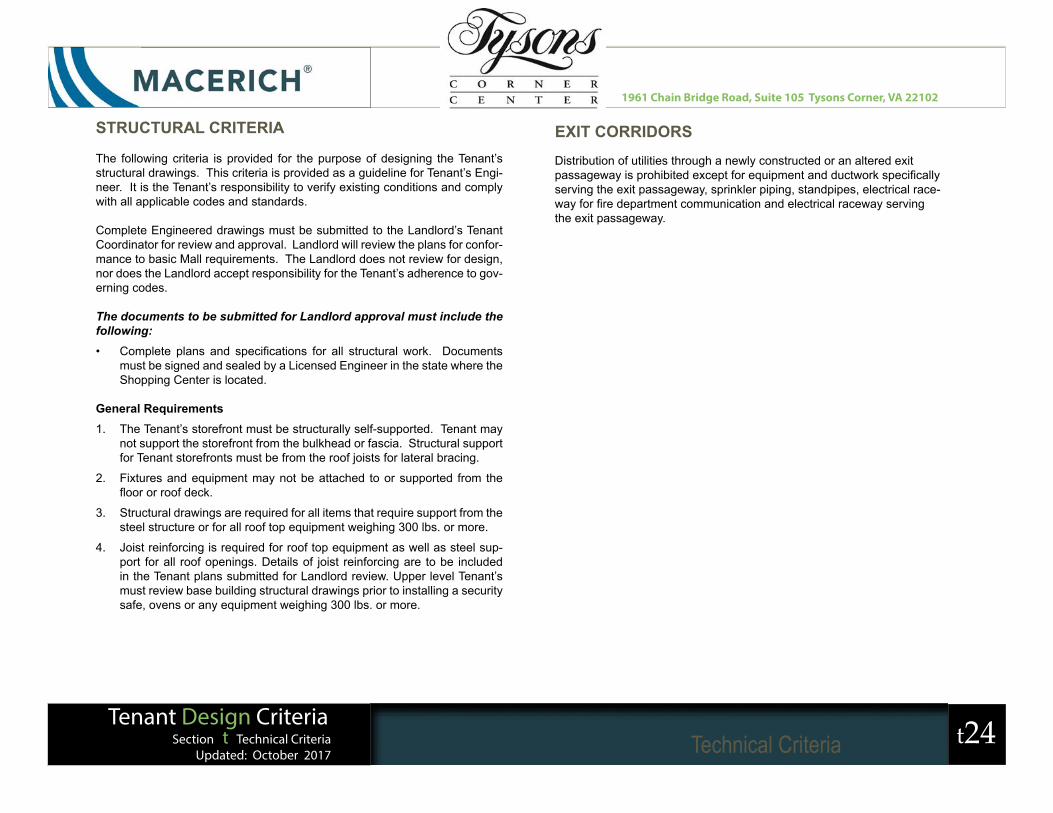
The following criteria is provided for the purpose of designing the Tenant’s structural drawings. This criteria is provided as a guideline for Tenant’s Engi-neer. It is the Tenant’s responsibility to verify existing conditions and comply with all applicable codes and standards.
Complete Engineered drawings must be submitted to the Landlord’s Tenant Coordinator for review and approval. Landlord will review the plans for confor-mance to basic Mall requirements. The Landlord does not review for design, nor does the Landlord accept responsibility for the Tenant’s adherence to gov-erning codes.
The documents to be submitted for Landlord approval must include the following:• Complete plans and specifications for all structural work. Documents
must be signed and sealed by a Licensed Engineer in the state where the Shopping Center is located.
General Requirements1. The Tenant’s storefront must be structurally self-supported. Tenant may
not support the storefront from the bulkhead or fascia. Structural support forTenantstorefrontsmustbefromtheroofjoistsforlateralbracing.
2. Fixturesandequipmentmaynotbeattached toorsupported from thefloororroofdeck.
3. Structural drawings are required for all items that require support from the steel structure or for all roof top equipment weighing 300 lbs. or more.
4. Joist reinforcing is required for roof top equipment as well as steel sup-port forall roofopenings.Detailsof joist reinforcingare tobe includedin the Tenant plans submitted for Landlord review. Upper level Tenant’s must review base building structural drawings prior to installing a security safe, ovens or any equipment weighing 300 lbs. or more.
STRUCTURAL CRITERIA EXIT CORRIDORSDistribution of utilities through a newly constructed or an altered exit passagewayisprohibitedexceptforequipmentandductworkspecificallyserving the exit passageway, sprinkler piping, standpipes, electrical race-wayforfiredepartmentcommunicationandelectricalracewayservingthe exit passageway.
Tenant Design CriteriaTechnical Criteria
1961 Chain Bridge Road, Suite 105 Tysons Corner, VA 22102
t25Section t Technical CriteriaUpdated: October 2017
AHU COMMISSIONING START-UP CHECKLISTEXHIBIT A
Tenant Design CriteriaTechnical Criteria
1961 Chain Bridge Road, Suite 105 Tysons Corner, VA 22102
t26Section t Technical CriteriaUpdated: October 2017
EXHIBIT B - BELIMO SINGLE LINE DIAGRAM
Tenant Design CriteriaTechnical Criteria
1961 Chain Bridge Road, Suite 105 Tysons Corner, VA 22102
t27Section t Technical CriteriaUpdated: October 2017
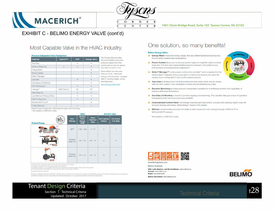
Belimo Energy Valve™
Solving Low Delta-T
Measures Energy
Controls Power
Manages Delta T
> Learn more www.energyvalve.com
EXHIBIT C - BELIMO ENERGY VALVE
Tenant Design CriteriaTechnical Criteria
1961 Chain Bridge Road, Suite 105 Tysons Corner, VA 22102
t28Section t Technical CriteriaUpdated: October 2017
EXHIBIT C - BELIMO ENERGY VALVE (cont’d)