Chapter 2 Design Geometrics and Criteria · Chapter 2 Design Geometrics and Criteria ... 2.9...
118
Topic #625-000-007 January 1, 2013 Plans Preparation Manual, Volume 1 - English Revised – January 1, 2015 Chapter 2 Design Geometrics and Criteria 2.0 General ...................................................................................... 2-1 2.0.1 Railroad-Highway Grade Crossing Near or Within Project Limits ............................................................. 2-3 2.1 Lanes ......................................................................................... 2-8 2.1.1 Travel Lanes and Auxiliary Lanes............................... 2-8 2.1.2 Other Lane Widths ..................................................... 2-9 2.1.3 Ramp Traveled Way Widths ..................................... 2-10 2.1.4 Pedestrian, Bicycle and Public Transit Facilities ....... 2-10 2.1.4.1 Pedestrian Facilities ................................. 2-10 2.1.4.2 Bicycle Facilities ....................................... 2-11 2.1.4.3 Public Transit Facilities ............................. 2-11 2.1.5 Cross Slopes ............................................................ 2-12 2.1.5.1 Hydroplaning Analysis .............................. 2-13 2.1.6 Roadway Pavement ................................................. 2-16 2.1.6.1 Alternative Roadway Paving Treatments ............................................... 2-16 2.1.6.2 Maintenance Memorandum of Agreement Requirements for Patterned Pavement ................................. 2-18 2.1.7 Transitions of Pavement Widths ............................... 2-20 2.1.8 Number of Lanes on the State Highway System ...... 2-20 2.2 Medians ................................................................................... 2-21 2.2.1 Median Width for Roadways..................................... 2-21 2.2.2 Multilane Facility Median Policy................................ 2-22 2.2.3 Median Treatments on Bridges ................................ 2-22 Design Geometrics and Criteria 2-i
Transcript of Chapter 2 Design Geometrics and Criteria · Chapter 2 Design Geometrics and Criteria ... 2.9...

Topic #625-000-007 January 1, 2013 Plans Preparation Manual, Volume 1 - English Revised – January 1, 2015
Chapter 2
Design Geometrics and Criteria
2.0 General ...................................................................................... 2-1
2.0.1 Railroad-Highway Grade Crossing Near or Within Project Limits ............................................................. 2-3
2.1 Lanes ......................................................................................... 2-8
2.1.1 Travel Lanes and Auxiliary Lanes............................... 2-8
2.1.2 Other Lane Widths ..................................................... 2-9
2.1.3 Ramp Traveled Way Widths ..................................... 2-10
2.1.4 Pedestrian, Bicycle and Public Transit Facilities ....... 2-10
2.1.4.1 Pedestrian Facilities ................................. 2-10
2.1.4.2 Bicycle Facilities ....................................... 2-11
2.1.4.3 Public Transit Facilities ............................. 2-11
2.1.5 Cross Slopes ............................................................ 2-12
2.1.5.1 Hydroplaning Analysis .............................. 2-13
2.1.6 Roadway Pavement ................................................. 2-16
2.1.6.1 Alternative Roadway Paving Treatments ............................................... 2-16
2.1.6.2 Maintenance Memorandum of Agreement Requirements for Patterned Pavement ................................. 2-18
2.1.7 Transitions of Pavement Widths ............................... 2-20
2.1.8 Number of Lanes on the State Highway System ...... 2-20
2.2 Medians ................................................................................... 2-21
2.2.1 Median Width for Roadways ..................................... 2-21
2.2.2 Multilane Facility Median Policy ................................ 2-22
2.2.3 Median Treatments on Bridges ................................ 2-22
Design Geometrics and Criteria 2-i

Topic #625-000-007 January 1, 2013 Plans Preparation Manual, Volume 1 - English Revised – January 1, 2015 2.3 Shoulders ................................................................................. 2-23
2.3.1 Limits of Friction Course on Paved Shoulders .......... 2-31
2.3.2 Shoulder Warning Devices (Rumble Strips) ............. 2-31
2.3.3 Use of Curb on High Speed Roadways .................... 2-32
2.4 Roadside Slopes ...................................................................... 2-33
2.5 Borders .................................................................................... 2-35
2.5.1 Limited Access Facilities .......................................... 2-38
2.6 Grades ..................................................................................... 2-39
2.7 Sight Distance .......................................................................... 2-42
2.8 Curves ..................................................................................... 2-45
2.8.1 Horizontal Curves ..................................................... 2-45
2.8.1.1 Supplemental Alignment Control (Mainline) ................................................. 2-45
2.8.1.2 Supplemental Alignment Control (Intersections) .......................................... 2-50
2.8.1.3 Roadway Transitions ................................ 2-50
2.8.2 Vertical Curves ......................................................... 2-51
2.9 Superelevation ......................................................................... 2-53
2.10 Vertical Clearance .................................................................... 2-59
2.10.1 Vertical Clearance Over Water ................................. 2-67
2.10.2 Horizontal Waterway Clearance ............................... 2-68
2.10.3 Regulatory Agency Requirements ............................ 2-68
2.10.4 Airspace Obstructions .............................................. 2-69
2.11 Lateral Offset ........................................................................... 2-71
Design Geometrics and Criteria 2-ii

Topic #625-000-007 January 1, 2013 Plans Preparation Manual, Volume 1 - English Revised – January 1, 2015 2.12 Bridge Railings and Separators ................................................ 2-80
2.13 Intersections ............................................................................. 2-93
2.13.1 Roundabouts ............................................................ 2-93
2.13.2 Queue Length for Unsignalized Intersections ........... 2-93
2.13.3 Offset Left Turn Lanes .............................................. 2-94
2.14 Interchanges and Median Openings/Crossovers ...................... 2-96
2.14.1 Limited Access Right of Way Limits at Interchanges ............................................................ 2-96
2.14.2 Median Openings at Interchanges ............................ 2-97
2.14.3 Ramp Widths ............................................................ 2-97
2.14.4 Crossovers on Limited Access Facilities .................. 2-99
2.15 Lighting Criteria ...................................................................... 2-105
2.16 High-Speed Urban and Suburban Arterial Highways .............. 2-105
2.16.1 Design Speed ......................................................... 2-107
2.16.2 Curbs ..................................................................... 2-107
2.16.3 Pedestrian and Bicycle Facilities ............................ 2-107
2.16.4 Medians ................................................................. 2-107
2.16.5 Shoulders ............................................................... 2-108
2.16.6 Friction Course ....................................................... 2-108
2.16.7 Border Width .......................................................... 2-108
2.16.8 Grades ................................................................... 2-108
2.16.9 Horizontal Curves ................................................... 2-109
2.16.10 Superelevation ....................................................... 2-109
2.16.11 Lateral Offset .......................................................... 2-110
Design Geometrics and Criteria 2-iii

Topic #625-000-007 January 1, 2013 Plans Preparation Manual, Volume 1 - English Revised – January 1, 2015 Tables
Table 2.1.1 Lane Widths ............................................................... 2-8
Table 2.1.2 Lane Widths - Special ................................................ 2-9
Table 2.1.3 Ramp Widths ............................................................ 2-10
Table 2.1.4 Maximum Algebraic Difference in Cross Slope at Turning Roadway Terminals ..................................... 2-15
Table 2.2.1 Median Widths ......................................................... 2-21
Table 2.3.1 Shoulder Widths and Cross Slopes - Freeways ................................................................. 2-24
Table 2.3.2 Shoulder Widths and Cross Slopes - Arterials Divided ....................................................... 2-25
Table 2.3.3 Shoulder Widths and Cross Slopes - Arterials Undivided ................................................... 2-26
Table 2.3.4 Shoulder Widths and Cross Slopes - Collectors Divided and Undivided ............................. 2-27
Table 2.4.1 Roadside Slopes ...................................................... 2-34
Table 2.5.1 Highways with Flush Shoulders ................................ 2-36
Table 2.5.2 Highways with Curb or Curb and Gutter in Urban Areas ............................................................. 2-37
Table 2.5.3 Limited Access Facilities .......................................... 2-38
Table 2.6.1 Maximum Grades ..................................................... 2-40
Table 2.6.2 Maximum Change in Grade Without Vertical Curves ......................................................... 2-40
Table 2.6.3 Criteria for Grade Datum .......................................... 2-41
Table 2.6.4 Grade Criteria for Curb and Gutter Sections ............. 2-41
Table 2.7.1 Minimum Stopping Sight Distance ............................ 2-43
Table 2.7.2 Minimum Passing Sight Distance ............................. 2-44
Table 2.8.1a Maximum Deflections without Horizontal Curves ...... 2-47
Design Geometrics and Criteria 2-iv
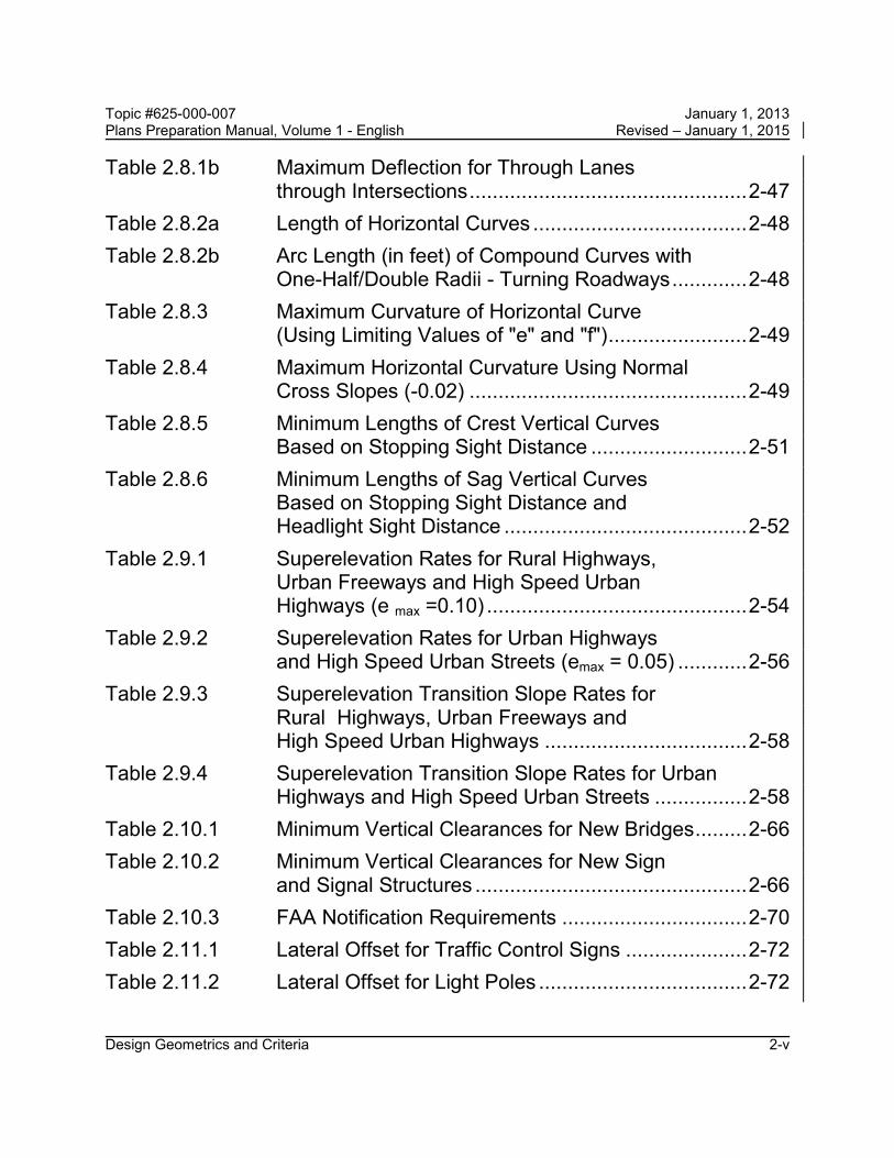
Topic #625-000-007 January 1, 2013 Plans Preparation Manual, Volume 1 - English Revised – January 1, 2015 Table 2.8.1b Maximum Deflection for Through Lanes
through Intersections ................................................ 2-47
Table 2.8.2a Length of Horizontal Curves ..................................... 2-48
Table 2.8.2b Arc Length (in feet) of Compound Curves with One-Half/Double Radii - Turning Roadways ............. 2-48
Table 2.8.3 Maximum Curvature of Horizontal Curve (Using Limiting Values of "e" and "f") ........................ 2-49
Table 2.8.4 Maximum Horizontal Curvature Using Normal Cross Slopes (-0.02) ................................................ 2-49
Table 2.8.5 Minimum Lengths of Crest Vertical Curves Based on Stopping Sight Distance ........................... 2-51
Table 2.8.6 Minimum Lengths of Sag Vertical Curves Based on Stopping Sight Distance and Headlight Sight Distance .......................................... 2-52
Table 2.9.1 Superelevation Rates for Rural Highways, Urban Freeways and High Speed Urban Highways (e max =0.10) ............................................. 2-54
Table 2.9.2 Superelevation Rates for Urban Highways and High Speed Urban Streets (emax = 0.05) ............ 2-56
Table 2.9.3 Superelevation Transition Slope Rates for Rural Highways, Urban Freeways and High Speed Urban Highways ................................... 2-58
Table 2.9.4 Superelevation Transition Slope Rates for Urban Highways and High Speed Urban Streets ................ 2-58
Table 2.10.1 Minimum Vertical Clearances for New Bridges ......... 2-66
Table 2.10.2 Minimum Vertical Clearances for New Sign and Signal Structures ............................................... 2-66
Table 2.10.3 FAA Notification Requirements ................................ 2-70
Table 2.11.1 Lateral Offset for Traffic Control Signs ..................... 2-72
Table 2.11.2 Lateral Offset for Light Poles .................................... 2-72
Design Geometrics and Criteria 2-v

Topic #625-000-007 January 1, 2013 Plans Preparation Manual, Volume 1 - English Revised – January 1, 2015 Table 2.11.3 Lateral Offset for Aboveground Fixed Utilities
(AFUs) ...................................................................... 2-73
Table 2.11.4 Lateral Offset to Traffic Infraction Detectors, Signal Poles and Controller Cabinets for Signals .... 2-74
Table 2.11.5 Lateral Offset to Trees .............................................. 2-74
Table 2.11.6 Lateral Offset to Bridge Piers and Abutments ........... 2-75
Table 2.11.7 Lateral Offset to Railroad Grade Crossing Traffic Control Devices ............................................. 2-76
Table 2.11.8 Lateral Offset to Canal and Drop-off Hazards ........... 2-76
Table 2.11.9 Lateral Offset to Other Roadside Obstacles ............. 2-76
Table 2.11.10 Lateral Offset for ITS Poles and Related Items ........ 2-77
Table 2.11.11 Recoverable Terrain ................................................. 2-78
Table 2.14.1 Ramp Widths - Turning Roadways ........................... 2-98
Figures
Figure 2.0.1 Partial Bridge Sections * ............................................. 2-4
Figure 2.0.2 Bridge Section * ......................................................... 2-5
Figure 2.0.3 Partial Bridge Sections * ............................................. 2-6
Figure 2.0.4 Bridge Section * ......................................................... 2-7
Figure 2.1.1 Standard Pavement Cross Slopes............................ 2-14
Figure 2.3.1.A Shoulder Superelevation .......................................... 2-28
Figure 2.3.1.B Special Shoulder Superelevation ............................. 2-29
Figure 2.3.2 Typical Paving Under Bridge .................................... 2-30
Figure 2.9.1 Superelevation Rate For Rural Highways, Urban Freeways and High Speed Urban Highways (e max =0.10) ............................................. 2-55
Figure 2.9.2 Superelevation Rates for Urban Highways and High Speed Urban Streets (emax = 0.05) ............ 2-57
Design Geometrics and Criteria 2-vi

Topic #625-000-007 January 1, 2013 Plans Preparation Manual, Volume 1 - English Revised – January 1, 2015 Figure 2.10.1 Clearances – Rural and Urban Interstates
(Freeways), Arterials and Collectors, with Projected 20-Year ADT of 1500 or Greater .............. 2-60
Figure 2.10.2 Clearances – Rural Arterials and Collectors with Projected 20-Year ADT of Less than 1500 ............... 2-61
Figure 2.10.3 Clearances – Urban Arterials and Collectors (Without Curb and Gutter) with Projected 20-Year ADT of Less than 1500 ............................... 2-62
Figure 2.10.4.A Clearances – Urban Arterials and Collectors (Curb and Gutter) ≤ 45 mph – Elevation of Bridge .... 2-63
Figure 2.10.4.B Clearances – Urban Arterials and Collectors (Curb and Gutter) ≤ 45 mph – Section through Bridge ....... 2-64
Figure 2.10.5 Clearances – Urban Arterials and Collectors (Curb and Gutter) with Traffic Barrier ....................... 2-65
Figure 2.11.1 Lateral Offset to Guardrail ........................................ 2-79
Figure 2.12.1 Bridge Traffic Railings – "F" Shapes ......................... 2-81
Figure 2.12.2 Bridge Traffic Railings – Vertical Shapes.................. 2-82
Figure 2.12.3 Bridge Traffic Railings – Other Shapes .................... 2-83
Figure 2.12.4 Bridge Traffic Railings – Noise Barrier Combination ............................................................. 2-84
Figure 2.12.5 Bridge Railing and Separators – Median Traffic Railing and Separators .................................. 2-85
Figure 2.12.6 Bridge Fencing for Traffic Railings............................ 2-86
Figure 2.12.7 Bridge Railing – Pedestrian / Bicycle Railing ............ 2-87
Figure 2.12.8 Bridge Railing – Pedestrian / Bicycle Railing ............ 2-88
Figure 2.12.9 Bridge Railing – Pedestrian / Bicycle Railing ............ 2-89
Figure 2.12.10 Bridge Railing – Pedestrian / Bicycle Retrofit Railing 2-90
Figure 2.12.11 Bridge Fencing for Pedestrian Railing ...................... 2-91
Figure 2.12.12 Enclosed Bridge Fencing for Pedestrian Railing ....... 2-92
Design Geometrics and Criteria 2-vii
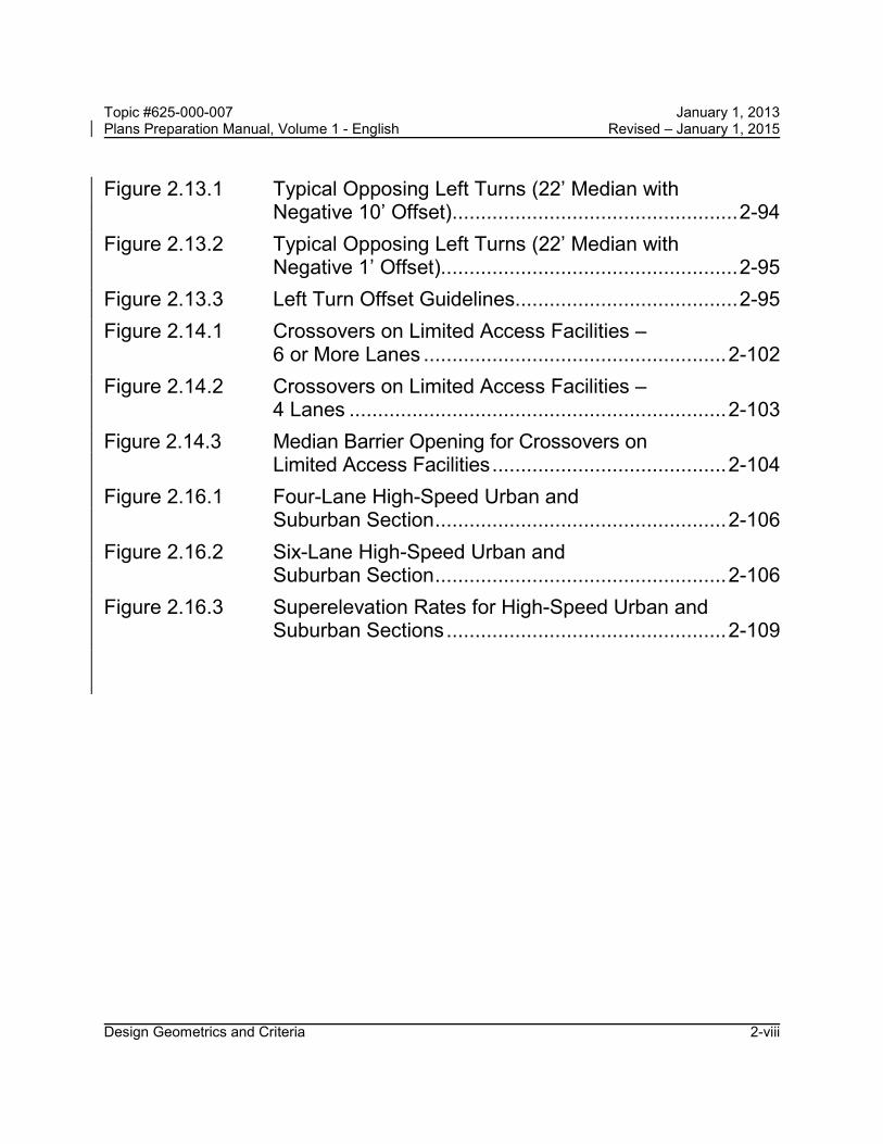
Topic #625-000-007 January 1, 2013 Plans Preparation Manual, Volume 1 - English Revised – January 1, 2015 Figure 2.13.1 Typical Opposing Left Turns (22’ Median with
Negative 10’ Offset) .................................................. 2-94
Figure 2.13.2 Typical Opposing Left Turns (22’ Median with Negative 1’ Offset).................................................... 2-95
Figure 2.13.3 Left Turn Offset Guidelines....................................... 2-95
Figure 2.14.1 Crossovers on Limited Access Facilities – 6 or More Lanes ..................................................... 2-102
Figure 2.14.2 Crossovers on Limited Access Facilities – 4 Lanes .................................................................. 2-103
Figure 2.14.3 Median Barrier Opening for Crossovers on Limited Access Facilities ......................................... 2-104
Figure 2.16.1 Four-Lane High-Speed Urban and Suburban Section ................................................... 2-106
Figure 2.16.2 Six-Lane High-Speed Urban and Suburban Section ................................................... 2-106
Figure 2.16.3 Superelevation Rates for High-Speed Urban and Suburban Sections ................................................. 2-109
Design Geometrics and Criteria 2-viii
Topic #625-000-007 January 1, 2013 Plans Preparation Manual, Volume 1 - English Revised – January 1, 2015
Chapter 2
Design Geometrics and Criteria
2.0 General
The implementation of design criteria is outlined in the following text. 1. Design Criteria: The design criteria presented in this manual are intended as
the principal source of criteria for the design of new construction or major reconstruction projects on the Florida State Highway System. These criteria are presented by subject for major design elements as fixed values or a range of acceptable values as defined by qualifiers. Where design criteria appear in the Design Standards, they will be consistent with the criteria in this manual. In addition, some criteria will remain in the other chapters of this manual. When conflicts are discovered, they should be brought to the attention of the State Roadway Design Engineer or State Structures Design Engineer, as applicable, for resolution.
Modification for Non-Conventional Projects:
Delete the last sentence of the above paragraph and replace with the following: Where conflicts exist, the EOR shall select the criteria proven to result in better safety performance.
On reconstruction projects, existing project features which were constructed to meet minimum metric design criteria, but are mathematically slightly less than equivalent minimum English design criteria, do not require Design Exceptions or Design Variations to remain. Design criteria for Resurfacing, Restoration, and Rehabilitation (RRR) are presented in Chapter 25 of this volume and are applicable only on programmed RRR projects.
Modification for Non-Conventional Projects:
Delete the sentence above and see RFP for requirements.
Facilities on the Strategic Intermodal System (SIS) are subject to special standards and criteria for number of lanes, design speed, access, level of service and other requirements.
Design Geometrics and Criteria 2-1

Topic #625-000-007 January 1, 2013 Plans Preparation Manual, Volume 1 - English Revised – January 1, 2015
SIS and Emerging SIS Highway Intermodal Connectors on the State Highway System (SHS) shall be designed in accordance with the SIS criteria contained in this manual. SIS and Emerging SIS Highway Intermodal Connectors on the local system (non-SHS) should also be designed in accordance with the SIS criteria contained in this manual, but the District may allow the use of the Manual of Uniform Minimum Standards for Design, Construction and Maintenance for Streets and Highways (commonly known as the "Florida Greenbook"), Topic No. 625-000-015 depending on project specifics, with approval by the District Design Engineer.
Modification for Non-Conventional Projects:
Delete the last sentence of the above paragraph and see RFP for requirements.
Design Criteria for roads that are not part of the State Highway System should be obtained from the Florida Greenbook.
Modification for Non-Conventional Projects:
Delete the last sentence.
2. Design Controls: Design controls are characteristics and conditions that influence or regulate the selection of the criteria for project standards. It is the designer's responsibility to recognize and apply those controls applicable to the project.
3. Design Standards: The specific values selected from the design criteria become the design standards for a design project. These standards will be identified and documented by the designer.
4. Project Parameters: The properties or specific conditions with limits which require modification of design standards within these limits. The designer is responsible for establishing and documenting any project parameters and their limits, as part of the justification for deviations from project standards.
Modification for Non-Conventional Projects:
Delete the last sentence of the above paragraph.
Many design standard considerations are related directly to the design speed, including vertical and horizontal geometry and required sight distances. The minimum design values are very closely related to traffic safety and cannot be compromised without an approved Design Exception or Design Variation. See Chapter 23 of this volume. Design Geometrics and Criteria 2-2

Topic #625-000-007 January 1, 2013 Plans Preparation Manual, Volume 1 - English Revised – January 1, 2015 Public facilities constructed or funded by FDOT (parking garages, weigh stations, operation centers, park & ride facilities, etc.) shall comply with the criteria in this manual, FDOT Design Standards, and other applicable Department manuals. Roads not on the State Highway System which are impacted by the construction of these public facilities should also be designed in accordance with Department criteria and standards, but the District may allow the use of the Florida Greenbook depending on project specifics.
Modification for Non-Conventional Projects:
Delete the last sentence of the above paragraph.
Roadway and bridge typical sections developed for projects must reflect the values and properties outlined in Items 1 - 4 of this section. These typical sections shall include the location and limits of such features as lanes, medians, shoulders, curbs, sidewalks, barriers, railings, etc.. Section 16.2.3 of this volume gives the requirements for approval and concurrence of typical section packages.
Coordination is of primary importance on projects that contain both roadway and bridge typical sections. The Roadway and Structures Offices must address the compatibility of the typical section features mentioned above, and provide for an integrated design and review process for the project.
Example roadway typical sections are included in the exhibits in Volume 2, Chapter 6. Partial bridge sections, Figures 2.0.1 - 2.0.4, provide criteria regarding lanes, medians, and shoulders for various facilities. Subsequent sections of this chapter contain specific information and criteria regarding these and other typical section elements, as well as geometric features of both roadways and bridges.
2.0.1 Railroad-Highway Grade Crossing Near or Within Project Limits
Federal-aid projects must be reviewed to determine if a railroad-highway grade crossing is in or near the limits of the project. If such railroad-highway grade crossing exists, the project must be upgraded in accordance with Section 6.2.3.
Design Geometrics and Criteria 2-3

Topic #625-000-007 January 1, 2013 Plans Preparation Manual, Volume 1 - English Revised – January 1, 2015
Design Geometrics and Criteria 2-4
Figure 2.0.1 Partial Bridge Sections *

Topic #625-000-007 January 1, 2013 Plans Preparation Manual, Volume 1 - English Revised – January 1, 2015
Design Geometrics and Criteria 2-5
Figure 2.0.2 Bridge Section *

Topic #625-000-007 January 1, 2013 Plans Preparation Manual, Volume 1 - English Revised – January 1, 2015
Design Geometrics and Criteria 2-6
Figure 2.0.3 Partial Bridge Sections *

Topic #625-000-007 January 1, 2013 Plans Preparation Manual, Volume 1 - English Revised – January 1, 2015
Design Geometrics and Criteria 2-7
Figure 2.0.4 Bridge Section *

Topic #625-000-007 January 1, 2013 Plans Preparation Manual, Volume 1 - English Revised – January 1, 2015
2.1 Lanes
Florida Department of Transportation (FDOT) criteria for lane widths and pavement slopes are given by highway type and area, through lanes, auxiliary lanes and other special lanes.
2.1.1 Travel Lanes and Auxiliary Lanes
Standard practice is to provide lane widths that are consistent with AASHTO Guidelines. See Table 2.1.1. Auxiliary lanes for speed change, turning and storage, and other purposes supplementary to through-traffic movement should be of the same width as the through lanes.
Table 2.1.1 Lane Widths LANE WIDTHS (FEET)
FACILITY TRAVEL LANES
AUXILIARY LANES
TYPE AREA SPEED CHANGE
TURNING (LT/RT/MED)
PASSING
FREEWAY Rural 12 12 ---- ---- Urban 12 12 ---- ----
ARTERIAL Rural 12 6 12 6 12 6 12 6
Urban 11 1 11 1 11 1,3 11 1
COLLECTOR Rural 12 5,6 11 2 11 2,3 11 2,4 Urban 11 11 11 3 11
1. 12 ft. for Design Speeds > 45 mph and for all undivided roadways 2. 12 ft. for 2-lane roadways 3 With severe R/W controls, 10 ft. turning lanes may be used where design speeds are
40 mph or less and the intersection is controlled by traffic signals. Median turn lanes shall not exceed 15 ft.
4.. 12 ft. when truck volume exceeds 10%. 5. 11 ft. for low volume AADT. 6. 11 ft. for divided roadways with Design Speeds ≤ 45 mph and within one mile of an
urban area.
Modification for Non-Conventional Projects:
Delete footnote 3 in PPM Table 2.1.1 above and see RFP for requirements.
Design Geometrics and Criteria 2-8
Topic #625-000-007 January 1, 2013 Plans Preparation Manual, Volume 1 - English Revised – January 1, 2015
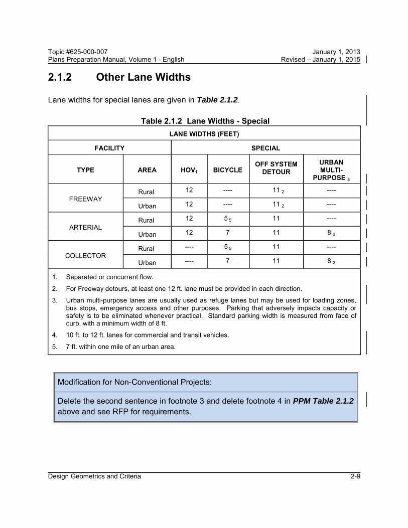
2.1.2 Other Lane Widths
Lane widths for special lanes are given in Table 2.1.2.
Table 2.1.2 Lane Widths - Special
LANE WIDTHS (FEET)
FACILITY
SPECIAL
TYPE
AREA
HOV1
BICYCLE OFF SYSTEM
DETOUR
URBAN MULTI-
PURPOSE 3
FREEWAY
Rural 12 ---- 11 2 ---- Urban 12 ---- 11 2 ----
ARTERIAL
Rural 12 5 5 11 ---- Urban 12 7 11 8 3
COLLECTOR
Rural ---- 5 5 11 ---- Urban ---- 7 11 8 3
1. Separated or concurrent flow.
2. For Freeway detours, at least one 12 ft. lane must be provided in each direction.
3. Urban multi-purpose lanes are usually used as refuge lanes but may be used for loading zones, bus stops, emergency access and other purposes. Parking that adversely impacts capacity or safety is to be eliminated whenever practical. Standard parking width is measured from face of curb, with a minimum width of 8 ft.
4. 10 ft. to 12 ft. lanes for commercial and transit vehicles.
5. 7 ft. within one mile of an urban area.
Modification for Non-Conventional Projects:
Delete the second sentence in footnote 3 and delete footnote 4 in PPM Table 2.1.2 above and see RFP for requirements.
Design Geometrics and Criteria 2-9

Topic #625-000-007 January 1, 2013 Plans Preparation Manual, Volume 1 - English Revised – January 1, 2015
2.1.3 Ramp Traveled Way Widths
Ramp widths for tangent and large radii (500 ft. or greater) sections are given in Table 2.1.3. Ramp widths in other areas such as terminals are controlled by the curvature and the vehicle type selected as the design control and are given in Table 2.14.1, Ramp Widths. Typical details for ramp terminals are provided in the Design Standards.
Table 2.1.3 Ramp Widths
RAMP WIDTHS (RAMP PROPER) FOR TANGENT AND LARGE RADII (≥ 500 ft.) SECTIONS
ONE LANE RAMPS 15 ft.
TWO LANE RAMPS 24 ft.
For ramp widths at turning roadways see Table 2.14.1.
2.1.4 Pedestrian, Bicycle and Public Transit Facilities
2.1.4.1 Pedestrian Facilities
Sidewalks and pedestrian crossings shall be considered on all projects. Although the standard sidewalk width is 5 feet, it may be desirable to create wider sidewalks in business districts, near schools, transit stops, or where there are other significant pedestrian attractors. The District Pedestrian/Bicycle Coordinator shall be consulted during planning and design to establish appropriate pedestrian elements on a project-by-project basis. Chapter 8 of this volume contains additional criteria for the accommodation of pedestrians.
Modification for Non-Conventional Projects:
Delete the above paragraph and replace with:
The standard sidewalk width is 5 feet. Chapter 8 of this volume contains additional criteria for the accommodation of pedestrians.
Design Geometrics and Criteria 2-10

Topic #625-000-007 January 1, 2013 Plans Preparation Manual, Volume 1 - English Revised – January 1, 2015
2.1.4.2 Bicycle Facilities
Bicycle facilities shall be provided as required by Chapter 8 of this volume. Bicycle lanes on the approaches to bridges should be continued across the structure. The District Pedestrian/Bicycle Coordinator shall be consulted during planning and design to establish appropriate bicycle facility elements on a project-by-project basis. Chapter 8 of this volume contains additional criteria for the accommodation of bicyclists.
Modification for Non-Conventional Projects:
Delete third sentence in above paragraph and see RFP for requirements.
2.1.4.3 Public Transit Facilities
Coordinate with the District Modal Development Office and local transit agency for the need for public transit facilities. Chapter 8 of this volume contains additional guidelines for street side bus stop facilities, location and design.
Modification for Non-Conventional Projects:
Delete first sentence in above paragraph and see RFP for requirements.
Design Geometrics and Criteria 2-11

Topic #625-000-007 January 1, 2013 Plans Preparation Manual, Volume 1 - English Revised – January 1, 2015
2.1.5 Cross Slopes
For roadways, the maximum number of travel lanes with cross slope in one direction is three lanes except as shown in Figure 2.1.1, which prescribes standard pavement cross slopes. The algebraic difference in cross slope between adjacent through lanes shall not exceed 0.04. The maximum algebraic difference in cross slope between a through lane and an auxiliary lane at a turning roadway terminal is given in Table 2.1.4. Chapter 4 on Roadside Safety and Chapter 8 on Pedestrian, Bicycle and Public Transit Facilities (this volume) contain additional procedures and guidelines on s lope design.
Cross slopes on bridges shall be on a uniform, straight-line rate, typically 0.02, in each traffic direction, with no break in slope. The straight-line slope shall be applied uniformly over all travel lanes and required shoulders in each direction of travel. Bridges with one-way traffic shall have one, uniform cross slope, while bridges with two-way traffic may be designed with a crowned bridge deck section.
This cross slope criteria applies to all bridge decks whether of cast-in-place concrete, precast concrete, or open steel decking.
Transitions shall be used to adjust for differences in cross slope between the approach roadway section and the required straight-line slope for bridge decks. Whenever possible the transition should be accomplished on the roadway section, outside the limits of the bridge and approach slabs. This will require detailing of the transition(s) in the roadway plans. Coordination between the Roadway, Drainage and Structures designers in the development of transitions is required to ensure compatibility and harmonizing at bridge approaches.
Design Geometrics and Criteria 2-12

Topic #625-000-007 January 1, 2013 Plans Preparation Manual, Volume 1 - English Revised – January 1, 2015
2.1.5.1 Hydroplaning Analysis
Figure 2.1.1 shows standard pavement cross slopes. Existing or proposed roadways exceeding the maximum allowable travel lanes with cross slope in one direction require that a Design Variation must be approved. At the discretion of the District, the Design Variation could include an assessment of the hydroplaning risk, including contributing shoulders, weighed against the expected cost savings from utilizing the existing or proposed section. This is intended for new construction and widening projects, and may be used for resurfacing or RRR projects.
Hydroplaning potential will be assessed by the HP program and the Design Guidance: Hydroplaning Risk Analysis, which can be downloaded at:
http://www.dot.state.fl.us/rddesign/Drainage/ManualsandHandbooks.shtm
Design Geometrics and Criteria 2-13

Topic #625-000-007 January 1, 2013 Plans Preparation Manual, Volume 1 - English Revised – January 1, 2015
Design Geometrics and Criteria 2-14
Figure 2.1.1 Standard Pavement Cross Slopes
All Travel Lanes One Direction
These sections show only the standard slopes for adjoining travel lanes; they do not prescribe needed lanes, lane usage or typical section requirements other than lane slope. These slopes are not applicable to parabolic crowns.
Maximum pavement cross slopes on tangent sections is 0.04.
The change in cross slope between adjacent through lanes shall not exceed 0.04.
Slopes on multi-purpose lanes may be 0.03 to 0.05. Portions of multi-purpose lanes that are reserved for parking and access isles for the physically disabled shall have cross slopes not exceeding 1:50 (0.02) in all directions.
*NOTE: For Design Speeds ≤ 65mph, a longitudinal slope that does not exceed 5% is acceptable on these sections.
The remaining sections are applicable for all design speeds.

Topic #625-000-007 January 1, 2013 Plans Preparation Manual, Volume 1 - English Revised – January 1, 2015
Design Geometrics and Criteria 2-15
Table 2.1.4 Maximum Algebraic Difference in Cross Slope at Turning Roadway Terminals
Design Speed of Exit or Entrance Curve (mph) Maximum Algebraic Difference in Cross Slope at Crossover Line (%)
Less than 35 6.0
35 and over 5.0
Topic #625-000-007 January 1, 2013 Plans Preparation Manual, Volume 1 - English Revised – January 1, 2015
2.1.6 Roadway Pavement
The type of pavement usually is determined by analysis of the volume and composition of traffic, the soil conditions, the availability of materials, the initial cost and the estimated cost of maintenance.
Criteria and procedures for selecting the type of pavement and the structural design of the various surfacing courses are discussed in the Department’s pavement design manuals.
2.1.6.1 Alternative Roadway Paving Treatments
Alternative paving treatments, such as patterned pavement and architectural pavers meeting FDOT Specifications, may be used for enhancing aesthetics and appearance when requested by a local community, and when the conditions and restrictions provided in this section are met. Patterned pavement treatments are covered under Section 523 of the FDOT Specifications and are surface markings applied either as an overlay to the pavement surface or imprinted in the pavement surface. Architectural pavers are covered under Section 526 of the FDOT Specifications and consist of brick pavers or concrete pavers placed on specially prepared bedding material.
These alternative pavement treatments are purely aesthetic treatments and are not considered to be traffic control devices. Use of either of these treatments is highly restricted as stated below. Even when all conditions and restrictions are met, any decision to use these treatments should consider that there may be potential adverse impacts to the traveling public as well as potential long term maintenance problems. Architectural pavers have been found to create significant ride-ability problems even on low speed roadways. Therefore, architectural pavers are prohibited within the traveled way on the State Highway System. Properly installed patterned pavement treatments do not significantly affect ride-ability; however, their use is also restricted since they are not likely to sustain their friction and wear characteristics for the full life of typical roadway pavement.
These paving treatments involve additional construction and maintenance costs not associated with typical roadway pavement. Therefore, appropriate agreements with the local maintaining agency shall be obtained. The local maintaining agency shall provide the additional funding for construction and assume responsibility for regular inspection and maintenance of the pavement treatment. In cases where existing alternative pavement is being removed as part of a Department project, replacement of such pavement shall adhere to the requirements in this section regardless of the circumstances of the original installation and maintenance. Maintenance agreements for installations within the traveled way on the State Highway System shall include the provisions outlined in Section 2.1.6.2 for the duration of the installation.
Design Geometrics and Criteria 2-16

Topic #625-000-007 January 1, 2013 Plans Preparation Manual, Volume 1 - English Revised – January 1, 2015 The following restrictions apply:
Architectural Pavers: 1. Shall not be used on the traveled way of the State Highway System. 2. May be used on local side streets (with a design speed of 35 mph or less), non-
traffic medians and islands, curb extensions, sidewalks, borders, and other areas not subject to vehicle traffic.
3. ADA requirements shall be met in areas subject to pedestrian traffic. See PROWAG R301.5 and R301.7 and ADAAG 302 and 303 for surface requirements.
Patterned Pavement: 1. Use on the traveled way of the State Highway System is restricted to areas within
marked pedestrian crosswalks where the design speed is 45 mph or less; however, patterned pavement shall not be used on pedestrian crosswalks across limited access roadway ramps. Use on pedestrian crosswalks with heavy truck traffic turning movements (≥ 10% trucks) should be avoided.
2. The pavement to which the treatment is applied shall be of the same pavement type as, and continuous with, the adjoining pavement. For example, replacing flexible pavement with rigid patterned pavement within the limits of a crosswalk where the abutting pavement is to remain flexible pavement will likely result in pavement joint problems and adverse impacts to rideability. This type treatment is therefore not permitted. Replacing flexible pavement with rigid pavement for an entire intersection including crosswalks may be permitted with a Technical Special Provision submitted to the State Roadway Design Engineer for approval.
3. The initial treatment cannot be applied to any State Highway whose asphalt pavement surface is older than 5 years.
4. May be used in areas not subject to vehicle traffic such as median islands, curb extensions, sidewalks, and landscaping borders.
5. ADA requirements shall be met in areas subject to pedestrian traffic. See PROWAG R301.5 and R301.7 and ADAAG 302 and 303 for surface requirements.
When architectural pavers are used, the plans shall identify the location, type, pattern, shape and color. In addition, project specific details and requirements for edge restraints, bedding material thickness, and base and sub-base materials and thicknesses, as appropriate, must be developed and included in the plans, which shall be signed and sealed by a licensed Florida Professional Engineer.
Design Geometrics and Criteria 2-17

Topic #625-000-007 January 1, 2013 Plans Preparation Manual, Volume 1 - English Revised – January 1, 2015 When patterned pavement treatments are used, the plans shall identify the location, patterned type (brick, stone, etc.), and surface color. Because local agencies must fund and maintain these treatments, product brands, colors and patterns may be specified in the plans as long as the brand is listed on the APL at the time of use.
Design Variations to any of the requirements in this Section shall be approved by the District Design Engineer.
2.1.6.2 Maintenance Memorandum of Agreement Requirements for Patterned Pavement
Prior to the installation of patterned pavement crosswalks in intersections on the State Highway System, a Maintenance Memorandum of Agreement shall be entered into with the local government agency requesting this aesthetic enhancement to the project. This agreement shall be filed with the District Maintenance Office. This Agreement shall require the local government agency to acknowledge that the installation and maintenance of patterned pavement is the total responsibility of the local agency, including contracting for friction testing with a qualified firm.
“Maintenance” of all patterned pavement crosswalks in these Agreements shall be defined, as a minimum, to include its frictional characteristics and integrity as follows:
1. Within 60 days of project acceptance by the Department, all lanes of each patterned crosswalk shall be evaluated for surface friction. The friction test shall be conducted using either a locked wheel tester in accordance with FM 5-592 (Florida Test Method for Friction Measuring Protocol for Patterned Pavements) or a Dynamic Friction Tester in accordance with ASTM E1911. FM 5-592 can be accessed at the following link: http://materials.dot.state.fl.us/smo/administration/resources/library/publications/fstm/Methods/fm5-592.pdf The initial friction resistance shall be at least 35 obtained at 40 mph with a ribbed tire test (FN40R) or equivalent. Failure to achieve this minimum resistance shall require all deficient crosswalk areas to be removed to their full extent (lane-by-lane) and replaced with the same product installed initially. If the Department determines that more than 50% of the lanes in the intersection require replacement, the entire intersection installation may be reconstructed with a different product on the Approved Products List (APL) or replaced with conventional pavement.
2. Approximately one year after project acceptance and every two years thereafter and for the life of the adjacent pavement, only the outside traffic lane areas of
Design Geometrics and Criteria 2-18

Topic #625-000-007 January 1, 2013 Plans Preparation Manual, Volume 1 - English Revised – January 1, 2015
each patterned crosswalk shall be tested for friction resistance in accordance with ASTM E274 or ASTM E1911. Friction resistance shall, at a minimum, have a FN40R value of 35 (or equivalent).
3. The results of all friction tests shall be sent to the District’s Warranty Coordinator with a cover letter either certifying that the crosswalks comply with the minimum friction criteria, or stating what remedial action will be taken to restore the friction.
4. Failure to achieve the minimum resistance shall require all lanes of the crosswalk to be friction tested to determine the extent of the deficiency. All deficient areas shall be removed to their full extent (lane-by-lane) and replaced with the same product installed initially. If the Department determines that more than 50% of the lanes in the intersection require replacement, the entire intersection installation may be reconstructed with a different product on the APL or replaced with conventional pavement.
5. When remedial action is required in accordance with the above requirements, the local agency shall complete all necessary repairs at its own expense within 90 days of the date when the deficiency was identified. No more than two full depth patterned pavement repairs shall be made to an area without first resurfacing the underlying pavement to 1” minimum depth.
6. The Department will not be responsible for replacing the treatment following any construction activities in the vicinity of the treatment.
7. Should the local agency fail to satisfactorily perform any required remedial work in accordance with this agreement, the Department reserves the right to replace the patterned pavement with conventional pavement (matching the adjacent pavement) and bill the local agency for this cost.
Design Geometrics and Criteria 2-19

Topic #625-000-007 January 1, 2013 Plans Preparation Manual, Volume 1 - English Revised – January 1, 2015
2.1.7 Transitions of Pavement Widths
When new pavement widths are not substantially greater than the joining pavement, grade differentials are slight and future widening is expected, striped transitions may be considered. An alternative approach is an abrupt change in width, with appropriate pavement markings, reflectors and rumble strips. The Design Standards contain additional criteria and details.
2.1.8 Number of Lanes on the State Highway System
For the number of lanes to be provided on the State Highway System, see Section 335.02(3) of the Florida Statutes.
Nothing in s. 335.02(3), F.S., precludes a number of lanes in excess of ten lanes. However, before the Department may determine the number of lanes should be more than that, the availability of right of way and the capacity to accommodate other modes of transportation within existing rights of way must be considered.
Exceptions to s. 335.02(3), F.S. will be addressed on a case-by-case basis, with final approval resting with the Secretary of Transportation.
Design Geometrics and Criteria 2-20

Topic #625-000-007 January 1, 2013 Plans Preparation Manual, Volume 1 - English Revised – January 1, 2015
2.2 Medians
2.2.1 Median Width for Roadways
Median widths for roadways are given in Table 2.2.1.
Table 2.2.1 Median Widths
MEDIAN WIDTHS (FEET)
TYPE FACILITY
WIDTH
FREEWAYS
Interstate, Without Barrier 64 1
Other Freeways, Without Barrier
---
Design Speed ≥ 60 mph
60
Design Speed < 60 mph
40
All, With Barrier, All Design Speeds
26 2
ARTERIAL AND COLLECTORS
Design Speed > 45 mph
40
Design Speed ≤ 45 mph
22 3
Paved And Painted For Left Turns
12 4
Median width is the distance between the inside (median) edge of the travel lane of each roadway.
1 88 ft. when future lanes planned.
2. Based on 2 ft. median barrier and 12 ft. shoulder.
3. On reconstruction projects where existing curb locations are fixed due to severe right of way constraints, the minimum width may be reduced to 19.5 ft. for design speeds = 45 mph, and to 15.5 ft. for design speeds ≤ 40 mph.
4. Restricted to 5-lane sections with design speeds ≤ 40 mph. On reconstruction projects where existing curb locations are fixed due to severe right of way constraints, the minimum width may be reduced to 10 ft. These flush medians are to include sections of raised or restrictive median for pedestrian refuge and to conform to Section 2.2.2 of this volume and the Access Management Rules.
Design Geometrics and Criteria 2-21

Topic #625-000-007 January 1, 2013 Plans Preparation Manual, Volume 1 - English Revised – January 1, 2015
2.2.2 Multilane Facility Median Policy
All multilane SIS facilities shall be designed with a raised or restrictive median. All other multilane facilities shall be designed with a raised or restrictive median except four-lane sections with design speeds of 40 mph or less. Facilities having design speeds of 40 mph or less are to include sections of raised or restrictive median for enhancing vehicular and pedestrian safety, improving traffic efficiency, and attainment of the standards of the Access Management Classification of that highway system.
2.2.3 Median Treatments on Bridges
For divided highways, the District will determine the desired distance between structures. Figures 2.0.1 and 2.0.3 in this chapter, indicate that a full deck is recommended if the open space between the bridges is 20 ft. or less and required when less than 10 ft. For structures with less than 20 ft. of clearance, consult with District Structures Design and Facilities Maintenance before making a final decision.
Each District Office, in deciding on a single structure deck or twin bridges, must take into account the inspection and maintenance capabilities of its personnel and equipment. If the total width for a single structure exceeds the capacity of district maintenance equipment (approximately 60 ft. reach), twin structures may be specified and the open distance between structures determined by the practical capability of the maintenance and inspection equipment. This is particularly important for girder superstructures because those areas that cannot be reached by topside equipment might require catwalks, ladders or other access features. Such features will add to the cost of superstructures and must be accounted for in the initial selection of alternates.
Design Geometrics and Criteria 2-22

Topic #625-000-007 January 1, 2013 Plans Preparation Manual, Volume 1 - English Revised – January 1, 2015
2.3 Shoulders
Roadway shoulder width, cross slope and superelevation criteria are provided in the criteria tables and figures. Paved outside shoulders, 5 ft. in width, are required on all new construction, reconstruction and lane addition projects for all highways except freeways, which generally require a 10 ft. paved outside shoulder.
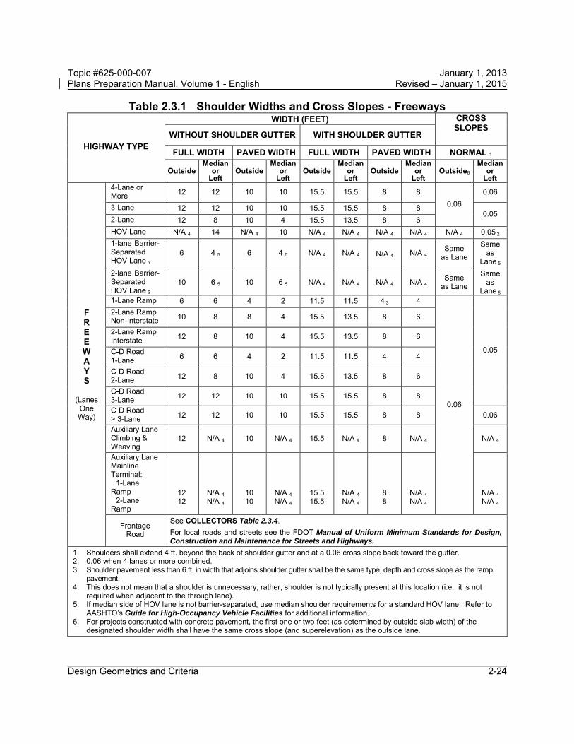
Specific widths have also been adopted for interstate, expressway, single and double lane ramps and collector-distributor road shoulders. Total shoulder widths, paved shoulder widths, and widths of paved shoulder separations between through pavement edge and the near edge of any shoulder gutter are given for both right (outside) and left (inside) edges of the roadway. See Tables 2.3.1 – 2.3.4 and Figures 2.3.1 – 2.3.2.
The Design Standards, Index 104, provides additional details for paved shoulders.
Figures 2.0.1 and 2.0.2 include criteria for shoulder widths on various bridge sections. Where these widths differ from those required for roadways or ramps, decisions about the final values chosen for the project must be coordinated between the Roadway and Structures Design Offices.
Generally, the outside shoulder width for bridges should be the same width as the approach roadway shoulder up to a maximum of 10 feet. On roadway alignments having 12 ft. shoulders with continuous barrier walls and closely spaced bridges, a 12 ft. bridge shoulder width may be considered. The decision to use 12 ft. bridge shoulder widths should be coordinated with the District Design Engineer.
Modification for Non-Conventional Projects:
Delete last sentence in above paragraph and see RFP for bridge shoulder width requirements.
For shoulder cross slope criteria on bridges see Section 2.1.5 of this chapter.
It is recommended to pave the median section and a 10 foot outside shoulder under overpass bridges. In addition, miscellaneous asphalt should be placed from the paved shoulder to the slope pavement. This pavement will provide additional safety, enhance drainage, reduce maintenance and improve appearance. See Figure 2.3.2.
For paved shoulders at railroad crossings see the Design Standards, Index 560.
Design Geometrics and Criteria 2-23
Topic #625-000-007 January 1, 2013 Plans Preparation Manual, Volume 1 - English Revised – January 1, 2015
Table 2.3.1 Shoulder Widths and Cross Slopes - Freeways
HIGHWAY TYPE
WIDTH (FEET) CROSS SLOPES
WITHOUT SHOULDER GUTTER WITH SHOULDER GUTTER
FULL WIDTH PAVED WIDTH
FULL WIDTH
PAVED WIDTH
NORMAL 1
Outside Median
or Left
Outside Median
or Left
Outside Median
or Left
Outside Median
or Left
Outside6
Median or
Left
F R E E W A Y S
(Lanes One Way)
4-Lane or More 12 12 10 10 15.5 15.5 8 8
0.06 0.06
3-Lane 12 12 10 10 15.5 15.5 8 8 0.05
2-Lane 12 8 10 4 15.5 13.5 8 6 HOV Lane N/A 4 14 N/A 4 10 N/A 4 N/A 4 N/A 4 N/A 4 N/A 4 0.05 2 1-lane Barrier-Separated HOV Lane 5
6 4 5 6 4 5 N/A 4 N/A 4 N/A 4 N/A 4 Same
as Lane
Same as
Lane 5 2-lane Barrier-Separated HOV Lane 5
10 6 5 10 6 5 N/A 4 N/A 4 N/A 4 N/A 4 Same
as Lane
Same as
Lane 5 1-Lane Ramp 6 6 4 2 11.5 11.5 4 3 4
0.06
0.05
2-Lane Ramp Non-Interstate 10 8 8 4 15.5 13.5 8 6
2-Lane Ramp Interstate 12 8 10 4 15.5 13.5 8 6
C-D Road 1-Lane 6 6 4 2 11.5 11.5 4 4
C-D Road 2-Lane 12 8 10 4 15.5 13.5 8 6
C-D Road 3-Lane 12 12 10 10 15.5 15.5 8 8
C-D Road > 3-Lane 12 12 10 10 15.5 15.5 8 8 0.06
Auxiliary Lane Climbing & Weaving
12 N/A 4 10 N/A 4 15.5 N/A 4 8 N/A 4 N/A 4
Auxiliary Lane Mainline Terminal: 1-Lane Ramp 2-Lane Ramp
12 12
N/A 4 N/A 4
10 10
N/A 4 N/A 4
15.5 15.5
N/A 4 N/A 4
8 8
N/A 4 N/A 4
N/A 4 N/A 4
Frontage Road
See COLLECTORS Table 2.3.4. For local roads and streets see the FDOT Manual of Uniform Minimum Standards for Design, Construction and Maintenance for Streets and Highways.
1. Shoulders shall extend 4 ft. beyond the back of shoulder gutter and at a 0.06 cross slope back toward the gutter. 2. 0.06 when 4 lanes or more combined. 3. Shoulder pavement less than 6 ft. in width that adjoins shoulder gutter shall be the same type, depth and cross slope as the ramp
pavement. 4. This does not mean that a shoulder is unnecessary; rather, shoulder is not typically present at this location (i.e., it is not
required when adjacent to the through lane). 5. If median side of HOV lane is not barrier-separated, use median shoulder requirements for a standard HOV lane. Refer to
AASHTO’s Guide for High-Occupancy Vehicle Facilities for additional information. 6. For projects constructed with concrete pavement, the first one or two feet (as determined by outside slab width) of the
designated shoulder width shall have the same cross slope (and superelevation) as the outside lane.
Design Geometrics and Criteria 2-24

Topic #625-000-007 January 1, 2013 Plans Preparation Manual, Volume 1 - English Revised – January 1, 2015
Table 2.3.2 Shoulder Widths and Cross Slopes - Arterials Divided
HIGHWAY TYPE
WIDTH (FEET) CROSS SLOPES WITHOUT
SHOULDER GUTTER WITH
SHOULDER GUTTER FULL WIDTH PAVED WIDTH FULL WIDTH PAVED WIDTH NORMAL 1
Outside Median
or Left
Outside2,7 Median
or Left
Outside Median
or Left
Outside7
Median or
Left Outside 6
Median or
Left
ARTERI ALS
Divided (Lanes
One Way)
4-Lane 12 10 8
12 10 8
555
444
15.5 15.5 15.5
15.5 15.5 13.5
886
886
0.06
0.06
3-Lane 12 10 8
12 10 8
555
0 40 40 4
15.5 15.5 13.5
15.5 15.5 13.5
886
886
0.05
2-Lane 12 10 8
886
555
0 40 40 4
15.5 15.5 13.5
13.5 13.5 11.5
886
664
1-Lane Ramp 6 6 5 2 11.5 11.5 4 3 4 2-Lane Ramp 10 6 5 2 15.5 13.5 8 6 C-D Road 1-Lane 6 6 5 2 11.5 11.5 4 4
C-D Road 2-Lane 8 6 5 0 13.5 11.5 6 4
Auxiliary Lane Climbing & Weaving
Same As
Travel Lanes
N/A 5
Same As
Travel Lanes
N/A 5
Same As
Travel Lanes
N/A 5
Same As
Travel Lanes
N/A 5 N/A 5
Auxiliary Lane Mainline Terminal:
1-Lane Ramp
2-Lane Ramp
8 12
N/A 5 N/A 5
5 10
N/A 5 N/A 5
11.5 15.5
N/A 5 N/A 5
48
N/A 5 N/A 5
N/A 5 N/A 5
Auxiliary Lane At-Grade Intersection
Same As
Travel Lanes
Same As
Travel Lanes
5 0 11.5 N/A 5 4 N/A 5 0.05 -
0.06
Frontage Road
See Collectors Table 2.3.4. For local roads and streets see the FDOT Manual of Uniform Minimum Standards for Design, Construction and Maintenance for Streets and Highways.
1. Shoulders shall extend 4 ft. beyond the back of shoulder gutter and have a 0.06 cross slope back toward the gutter.2. Shoulder shall be paved full width through rail-highway at-grade crossings, extending a minimum distance of 50 ft. on each
side of the crossing measured from the outside rail. For additional information see the Design Standards, Index No. 560and 17882.
3. Shoulder pavement less than 6 ft. in width and adjoining shoulder gutter shall be the same type, depth and cross slope as theramp pavement.
4. Paved 2 ft. wide where turf is difficult to establish. Paved 4 ft. wide (a) in sag vertical curves, 100 ft. minimum either side ofthe low point, and (b) on the low side of superelevated traffic lanes extending through the curves and approximately 300 ft.beyond the PC and PT.
LEGEND X ........ High Volume Highways FOR X ........ Normal Volume Highways VALUES X ........ Low Volume Highways
5. This does not mean that a shoulder is unnecessary; rather, shoulder is not typically present at this location (i.e., it is notrequired when adjacent to through lane).
6. For projects constructed with concrete pavement, the first one or two feet (as determined by outside slab width) of thedesignated shoulder width shall have the same cross slope (and superelevation) as the outside lane.
7. 7 feet in or within one mile of an urban area.
Design Geometrics and Criteria 2-25

Topic #625-000-007 January 1, 2013 Plans Preparation Manual, Volume 1 - English Revised – January 1, 2015
Table 2.3.3 Shoulder Widths and Cross Slopes - Arterials Undivided
HIGHWAY TYPE
WIDTHS (FEET) CROSS SLOPES
WITHOUT SHOULDER GUTTER
WITH SHOULDER GUTTER
NORMAL 1, 4
FULL WIDTH
PAVED WIDTH 2
FULL WIDTH
PAVED WIDTH
0.06 ARTERIALS Undivided
(lanes Two-Way)
Multilane 3 12 10 8
5 5 5
15.5 15.5 13.5
8 8 6
2-Lane 12 10 8
5 5 5
15.5 15.5 13.5
8 8 6
Auxiliary Lane At-Grade Intersections
Same As
Travel Lanes
5 11.5 4
Frontage Road
See COLLECTORS Table 2.3.4. For local roads and streets see the FDOT Manual of Uniform Minimum Standards for Design, Construction and Maintenance for Streets and Highways.
1. Shoulders shall extend 4 ft. beyond the back of shoulder gutter and have a 0.06 cross slope back toward the gutter.
2. Shoulder shall be paved full width through rail-highway at-grade crossings, extending a minimum distance of 50 ft. on each side of the crossing measured from the outside rail. For additional information see the Design Standards, Index No. 560 and 17882.
3. All multilane facilities shall conform with Section 2.2.2 of this Volume. LEGEND X ....... High Volume Highways FOR X ....... Normal Volume Highways VALUES X ....... Low Volume Highways 4. For projects constructed with concrete pavement, the first one or two feet (as determined by outside
slab width) of the designated shoulder width shall have the same cross slope (and superelevation) as the outside lane.
Design Geometrics and Criteria 2-26

Topic #625-000-007 January 1, 2013 Plans Preparation Manual, Volume 1 - English Revised – January 1, 2015
Table 2.3.4 Shoulder Widths and Cross Slopes - Collectors Divided and Undivided
HIGHWAY TYPE
WIDTHS (FEET) CROSS SLOPES WITHOUT SHOULDER GUTTER WITH SHOULDER GUTTER
FULL WIDTH
PAVED WIDTH
FULL WIDTH
PAVED WIDTH NORMAL 1
Outside Median
Or Left
Outside Median
Or Left
Outside Median
Or Left
Outside7
Median Or
Left
Outside 6 Median
Or Left
C OL L E C T OR S
Divided (Lanes
One-Way)
3-Lane 12 10 8
12 10 8
555
0 30 30 3
15.5 15.5 13.5
15.5 15.5 15.5
886
886
0.06 0.05
2-lane 12 10 8
886
555
0 30 30 3
15.5 15.5 13.5
13.5 13.5 11.5
886
664
Auxiliary Lane
At-Grade Intersection
Same As
Travel Lanes
Same As
Travel Lanes
5 4 11.5 N/A 5 4 N/A 5
C OL L E C T OR S
Undivided (Lanes
Two-Way)
Multilane 4 12 10 8
555
15.5 15.5 13.5
886
0.06
2-Lane 12 10 8
555
15.5 15.5 13.5
886
Auxiliary Lane
At-Grade Intersection
Same As
Travel Lanes
Same As
Travel Lanes
11.5 4
1. Shoulders shall extend 4 ft. beyond the back of shoulder gutter and have a 0.06 cross slope back toward the gutter.2. Shoulder shall be paved full width though rail-highway at-grade crossings, extending a minimum distance of 50
ft. on each side of the crossing measured from the outside rail. For additional information see DesignStandards, Index Nos. 560 and 17882.
3. The median shoulder may be paved 2 ft. wide in areas of the State where establishing and maintaining turf isdifficult; however, shoulders shall be paved 4 ft. wide (a) in sag vertical curves, 100 ft. minimum either side of thelow point, and (b) on the low side of superelevated traffic lanes, extending through the curve and approximately300 ft. beyond the PC and PT.
4. All multilane facilities shall conform with Section 2.2.2 of this volume.LEGEND X ....... High Volume Highways
FOR X ....... Normal Volume Highways VALUES X ....... Low Volume Highways
5. This does not mean that a shoulder is unnecessary; rather, shoulder is not typically present at this location(i.e., it is not required when adjacent to through lane).
6. For projects constructed with concrete pavement, the first one or two feet (as determined by outside slab width) ofthe designated shoulder width shall have the same cross slope (and superelevation) as the outside lane.
7. 7 feet in or within one mile of an urban area.
Design Geometrics and Criteria 2-27
2,7

Topic #625-000-007 January 1, 2013 Plans Preparation Manual, Volume 1 - English Revised – January 1, 2015
Figure 2.3.1.A Shoulder Superelevation
* For projects constructed with concrete pavement, the shoulder shall be superelevated about the outside edge of the outside slab.
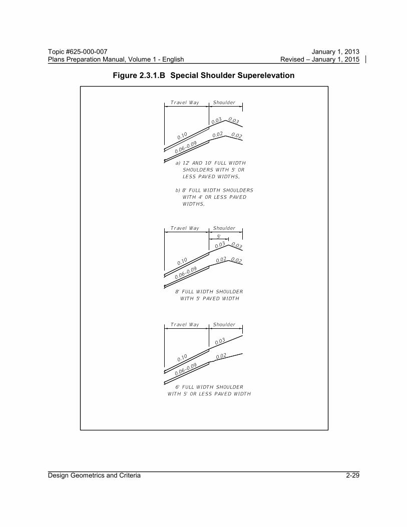
** For shoulders with paved widths 5 feet or less (all Highway Types) see Special Shoulder superelevation details (Figure 2.3.1.B).
Design Geometrics and Criteria 2-28
Topic #625-000-007 January 1, 2013 Plans Preparation Manual, Volume 1 - English Revised – January 1, 2015
Figure 2.3.1.B Special Shoulder Superelevation
Design Geometrics and Criteria 2-29

Topic #625-000-007 January 1, 2013 Plans Preparation Manual, Volume 1 - English Revised – January 1, 2015
Figure 2.3.2 Typical Paving Under Bridge
Design Geometrics and Criteria 2-30

Topic #625-000-007 January 1, 2013 Plans Preparation Manual, Volume 1 - English Revised – January 1, 2015
2.3.1 Limits of Friction Course on Paved Shoulders
Friction courses on limited access facilities shall be extended 8 inches onto both the median and outside paved shoulders of roadways.
Friction courses shall be extended the full width of the paved shoulder on non-limited access highways to accommodate bicyclist usage.
2.3.2 Shoulder Warning Devices (Rumble Strips)
The safety of freeways and other limited access facilities on the State highway system is to be enhanced by the installation of shoulder warning devices in the form of rumble strips. Projects on limited access facilities shall include the construction of ground-in rumble strips. Several types of applications have been tested. The ground-in strips provide the desired warning to the driver and consistency in application has been possible using this construction process.
These ground-in strips are installed using two patterns. The skip array is the standard array. These are used on both inside and outside shoulders on divided highway sections. The continuous array shall be constructed in advance of bridge ends for a distance of 1000 ft. or back to the gore recovery area for mainline interchange bridges. Other areas may be specified in plans.
Methods and types of application other than described above and in the Design Standards, Index 518, shall not be used unless concurred in by the State Roadway Design Engineer. Approval will be considered only with sufficient documented justification for deviation from the standard.
The Design Standards, Index 518, has been prepared to provide all needed details. This index also gives standards for raised rumble strips for use at structures where the bridge shoulder width is less than the width of the useable shoulder on the approach roadway. Notes for locations of raised rumble strip applications are also included on the index.
Design Geometrics and Criteria 2-31

Topic #625-000-007 January 1, 2013 Plans Preparation Manual, Volume 1 - English Revised – January 1, 2015
2.3.3 Use of Curb on High Speed Roadways
Curbs shall not be used on high speed roadways (Design Speed ≥ 50 mph) except as follows: 1. FDOT Suburban Section 2. FDOT High Speed Urban Section 3. Median Openings 4. Transit Stops
Curbs used on high speed roadways shall be FDOT Type E with the face of the curb placed no closer to the edge of the traveled way than the required full width shoulder for a flush shoulder roadway. For the Suburban and High Speed Urban Section, special offset widths to curb have been established. See Section 2.16 for requirements for High-Speed Urban and Suburban Arterial Highways. For directional median openings, see Index 527. For transit stops, the curb face shall be no closer to the edge of the traveled way than the required full width shoulder for a flush shoulder roadway.
Design Geometrics and Criteria 2-32

Topic #625-000-007 January 1, 2013 Plans Preparation Manual, Volume 1 - English Revised – January 1, 2015
2.4 Roadside Slopes
Criteria and details for roadside slopes are included in Table 2.4.1. For slopes steeper than 1:3, consider the associated long term erosion control and maintenance costs. Coordinate the use of these slopes with the Drainage, Maintenance and Landscape Architect’s Offices. For sod or turf slopes steeper than 1:3 and higher than 20 feet, include a 10 foot wide flat area at the top and base of the slope with clear access for maintenance equipment and personnel. For sod or turf slopes steeper than 1:3 and higher than 35 feet, include a 10 foot wide maintenance berm not more than every 35 feet from the top of the slope. Slopes steeper than 1:2 require coordination with the District Geotechnical Office.
Modification for Non-Conventional Projects:
Delete the second, third and last sentences in above paragraph and see RFP for requirements.
For walls 5 feet and higher, a 10 foot flat area shall be included from the face of an adjacent retaining wall allowing clear access for maintenance vehicles and personnel. (See SDG 3.12.)
Clear zone (CZ) criteria are included in Section 2.11 and Chapter 4 of this volume.
Design Geometrics and Criteria 2-33

Topic #625-000-007 January 1, 2013 Plans Preparation Manual, Volume 1 - English Revised – January 1, 2015
Table 2.4.1 Roadside Slopes
TYPE OF FACILITY
RURAL & URBAN FREEWAYS,
RURAL ARTERIALS AND COLLECTORS,
WITH PROJECTED 20 YEAR AADT OF 1500 OR GREATER
DESIGN SPEED
45 mph OR GREATER
RURAL ARTERIALS AND COLLECTORS WITH PROJECTED 20 YR. AADT LESS THAN 1500 AND RURAL LOCALS, URBAN ARTERIALS AND COLLECTORS WITHOUT CURB & GUTTER
ALL SPEEDS
URBAN ARTERIALS AND COLLECTORS WITH CURB & GUTTER
DESIGN SPEED
45 mph OR LESS
Height of Fill (feet) *
Rate
Height of Fill (feet) *
Rate
Height of Fill (feet) *
Rate
Front Slope
0.0 - 5
5 - 10
10 - 20
>20
1:6 1:6 to edge of CZ then 1:4 1:6 to edge of CZ then 1:3 1:2 (with guardrail)
0.0 - 5
5 - 20
1:6 Where R/W is insufficient, 1:6 to edge of CZ then 1:3 1:6 to edge of CZ then 1:3. Where, R/W is insufficient, 1:6 to edge of CZ then 1:2.
All
1:2 or to suit property owner, not flatter than 1:6. R/W cost must be considered for high fill sections in urban areas
Back Slope All
1:4 or 1:3 with a standard width trapezoidal ditch and 1:6 front slope
All 1:4 when R/W permits or 1:3 All
1:2 or to suit property owner. Not flatter than 1:6.
Transverse
Slopes
All
1:10 or flatter (freeways) 1:4 (others)
All 1:4 All 1:4
* Height of Fill is the vertical distance from the edge of the outside travel lane to the toe of front slope.
Design Geometrics and Criteria 2-34

Topic #625-000-007 January 1, 2013 Plans Preparation Manual, Volume 1 - English Revised – January 1, 2015
2.5 Borders
Border widths for new construction or major reconstruction where R/W acquisition is required are as follows:
On highways with flush shoulders, the border is measured from the shoulder point to the right of way line. This border width accommodates (1) roadside design components such as signing, drainage features, guardrail, fencing and clear zone, (2) the construction and maintenance of the facility and (3) permitted public utilities. See Table 2.5.1.
On highways with curb or curb and gutter where clear zone is being provided, border width is to be based on flush shoulder requirements, but is measured from the lip of the gutter (or face of curb when there is not a gutter) to the right of way line. This border width accommodates (1) roadside design components such as signing, drainage features, guardrail, fencing and clear zone, (2) the construction and maintenance of the facility and (3) permitted public utilities. See Table 2.5.1.
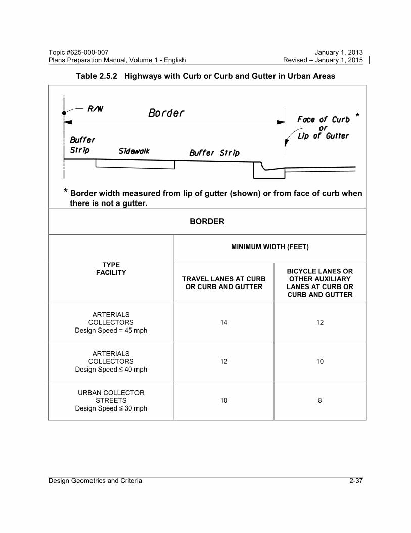
On highways with curb or curb and gutter in urban areas, the border is measured from the lip of the gutter (or face of curb when there is not a gutter) to the right of way line. This border provides space for a buffer between vehicles and pedestrians, sidewalks with ADA provisions, traffic control devices, fire hydrants, storm drainage features, bus and transit features, permitted public utilities and space for aesthetic features such as sod and other landscape items. See Table 2.5.2.
On limited access facilities, the border width criteria are provided in Section 2.5.1.
Projects involving bridges will require coordination to match the features of the roadway with those of the bridge.
Modification for Non-Conventional Projects:
Delete sentence above and see RFP for requirements on projects involving bridges.
On existing streets and highways where R/W cannot be acquired or where the decision has been made to simply maintain and preserve the facility, the border area must be reserved for the functional and safety needs of the facility. The absolute minimum border under these conditions is 8 feet.
Design Geometrics and Criteria 2-35

Topic #625-000-007 January 1, 2013 Plans Preparation Manual, Volume 1 - English Revised – January 1, 2015
Table 2.5.1 Highways with Flush Shoulders
BORDER
TYPE FACILITY WIDTH (FEET)
ARTERIALS COLLECTORS
Design Speed > 45 mph 40
ARTERIALS COLLECTORS
Design Speed ≤ 45 mph 33
Design Geometrics and Criteria 2-36
Topic #625-000-007 January 1, 2013 Plans Preparation Manual, Volume 1 - English Revised – January 1, 2015
Table 2.5.2 Highways with Curb or Curb and Gutter in Urban Areas
*
* Border width measured from lip of gutter (shown) or from face of curb when
there is not a gutter.
BORDER
TYPE FACILITY
MINIMUM WIDTH (FEET)
TRAVEL LANES AT CURB OR CURB AND GUTTER
BICYCLE LANES OR OTHER AUXILIARY
LANES AT CURB OR CURB AND GUTTER
ARTERIALS
COLLECTORS Design Speed = 45 mph
14 12
ARTERIALS
COLLECTORS Design Speed ≤ 40 mph
12 10
URBAN COLLECTOR
STREETS Design Speed ≤ 30 mph
10 8
Design Geometrics and Criteria 2-37

Topic #625-000-007 January 1, 2013 Plans Preparation Manual, Volume 1 - English Revised – January 1, 2015
2.5.1 Limited Access Facilities
On limited access facilities, the border is measured from the edge of the outside traffic lane to the right of way line. This width may be reduced in the area of a crossroad terminal, as long as the design meets the requirements for clear zone, lateral offsets, drainage, maintenance access, etc.
Limited access facilities shall be contained by fencing, or in special cases, walls or barriers. These treatments shall be continuous and appropriate for each location. Treatment height and type may vary under special conditions. The treatment is typically placed at or near the limited access right of way line, but location may be adjusted based on site-specific conditions (i.e., ponds, trees, bridges, etc.). Placement information and additional data is included in the Design Standards, Indexes 800, 801, and 802.
Modification for Non-Conventional Projects:
Delete third sentence in above paragraph and see RFP for requirements.
Table 2.5.3 Limited Access Facilities
BORDER
TYPE FACILITY WIDTH (FEET)
FREEWAYS (INCLUDING
INTERCHANGE RAMPS) 94
Design Geometrics and Criteria 2-38

Topic #625-000-007 January 1, 2013 Plans Preparation Manual, Volume 1 - English Revised – January 1, 2015
2.6 Grades
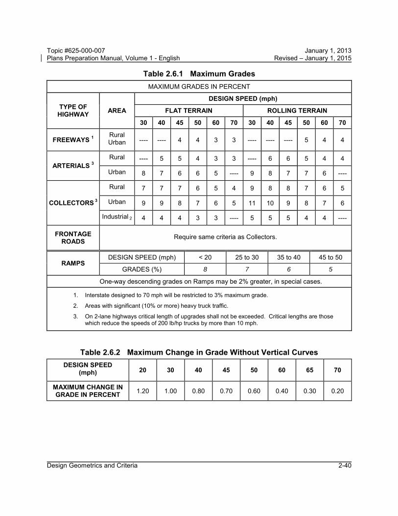
The profile grade line defines the vertical alignment for roadway and bridge construction. As with other design elements, the characteristics of vertical alignment are influenced greatly by basic controls related to design speed, traffic volumes, functional classification, drainage and terrain conditions. Within these basic controls, several general criteria must be considered. See Tables 2.6.1 – 2.6.4.
Minimum clearances for structures over railroads are given in Table 2.10.1. Additional information, including at-grade crossings, is given in Chapter 6 of this volume.
The Department's minimum for clearance over all highways is given in the criteria tables and figures. Exceptions to this policy shall be permitted only when justified by extenuating circumstances and approved as a Design Variation or Design Exception.
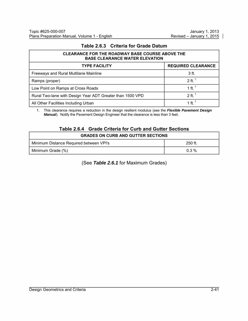
The clearance required for the roadway base course above the Base Clearance Water Elevation is given in the criteria tables and figures. The relationship between the pavement elevation and the Design Flood Elevation is discussed in Section 4.4 (3) of the FDOT Drainage Manual (Topic No. 625-040-002). Turnpike facilities are generally used for Hurricane Evacuation. Turnpike mainline travel lanes shall be above the 100 year flood plain elevation established by FEMA or other pertinent studies.
Grades for structures over water shall be designed to provide the minimum vertical clearance as stipulated in Section 2.10 of this chapter.
The Design Standards lists minimum covers and maximum fill heights for all types of culverts. For utility clearances, refer to the Utility Accommodation Manual.
Design Geometrics and Criteria 2-39
Topic #625-000-007 January 1, 2013 Plans Preparation Manual, Volume 1 - English Revised – January 1, 2015
Table 2.6.1 Maximum Grades MAXIMUM GRADES IN PERCENT
TYPE OF HIGHWAY AREA
DESIGN SPEED (mph)
FLAT TERRAIN ROLLING TERRAIN
30 40 45 50 60 70 30 40 45 50 60 70
FREEWAYS 1 Rural Urban ---- ---- 4 4 3 3 ---- ---- ---- 5 4 4
ARTERIALS 3 Rural ---- 5 5 4 3 3 ---- 6 6 5 4 4
Urban 8 7 6 6 5 ---- 9 8 7 7 6 ----
COLLECTORS 3
Rural 7 7 7 6 5 4 9 8 8 7 6 5
Urban 9 9 8 7 6 5 11 10 9 8 7 6
Industrial 2 4 4 4 3 3 ---- 5 5 5 4 4 ----
FRONTAGE ROADS
Require same criteria as Collectors.
RAMPS DESIGN SPEED (mph) < 20 25 to 30 35 to 40 45 to 50
GRADES (%) 8 7 6 5
One-way descending grades on Ramps may be 2% greater, in special cases.
1. Interstate designed to 70 mph will be restricted to 3% maximum grade.
2. Areas with significant (10% or more) heavy truck traffic.
3. On 2-lane highways critical length of upgrades shall not be exceeded. Critical lengths are those which reduce the speeds of 200 lb/hp trucks by more than 10 mph.
Table 2.6.2 Maximum Change in Grade Without Vertical Curves
DESIGN SPEED (mph) 20 30 40 45 50 60 65 70
MAXIMUM CHANGE IN GRADE IN PERCENT 1.20 1.00 0.80 0.70 0.60 0.40 0.30 0.20
Design Geometrics and Criteria 2-40
Topic #625-000-007 January 1, 2013 Plans Preparation Manual, Volume 1 - English Revised – January 1, 2015
Table 2.6.3 Criteria for Grade Datum CLEARANCE FOR THE ROADWAY BASE COURSE ABOVE THE
BASE CLEARANCE WATER ELEVATION
TYPE FACILITY REQUIRED CLEARANCE
Freeways and Rural Multilane Mainline 3 ft.
Ramps (proper) 2 ft. 1
Low Point on Ramps at Cross Roads 1 ft. 1
Rural Two-lane with Design Year ADT Greater than 1500 VPD 2 ft. 1
All Other Facilities Including Urban 1 ft. 1
1. This clearance requires a reduction in the design resilient modulus (see the Flexible Pavement Design Manual). Notify the Pavement Design Engineer that the clearance is less than 3 feet.
Table 2.6.4 Grade Criteria for Curb and Gutter Sections GRADES ON CURB AND GUTTER SECTIONS
Minimum Distance Required between VPI's 250 ft.
Minimum Grade (%) 0.3 %
(See Table 2.6.1 for Maximum Grades)
Design Geometrics and Criteria 2-41

Topic #625-000-007 January 1, 2013 Plans Preparation Manual, Volume 1 - English Revised – January 1, 2015
2.7 Sight Distance
Three aspects of sight distances should be considered:
1. Sight distances needed for stopping, which are applicable on all highways
2. Sight distances needed for the passing of overtaken vehicles, applicable only on two-lane highways
3. Sight distances needed for decisions at complex locations
The criteria used for stopping and decision sight distance are a driver’s eye height of 3.5 feet and an object height of 0.5 feet. The criteria used for passing sight distance is an object height of 3.5 feet.
Sight distances greater than the minimum stopping sight distances in Table 2.7.1 should be considered when drivers need additional time to make decisions. The AASHTO publication, A Policy on Geometric Design of Highways and Streets, has a thorough discussion on decision sight distance.
Minimum stopping and passing sight distances are given in Tables 2.7.1 – 2.7.2.
Design Geometrics and Criteria 2-42
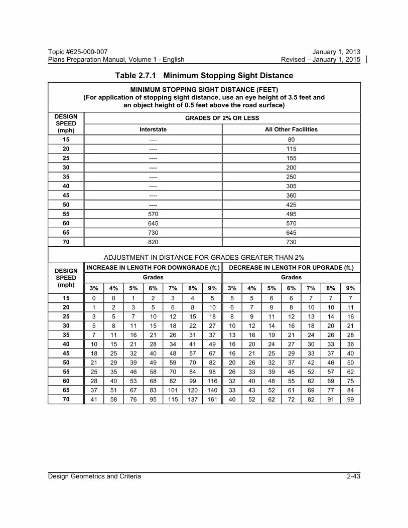
Topic #625-000-007 January 1, 2013 Plans Preparation Manual, Volume 1 - English Revised – January 1, 2015
Table 2.7.1 Minimum Stopping Sight Distance MINIMUM STOPPING SIGHT DISTANCE (FEET)
(For application of stopping sight distance, use an eye height of 3.5 feet and an object height of 0.5 feet above the road surface)
DESIGN SPEED (mph)
GRADES OF 2% OR LESS
Interstate All Other Facilities 15 ---- 80 20 ---- 115 25 ---- 155 30 ---- 200 35 ---- 250 40 ---- 305 45 ---- 360 50 ---- 425 55 570 495 60 645 570 65 730 645 70 820 730
ADJUSTMENT IN DISTANCE FOR GRADES GREATER THAN 2%
DESIGN SPEED (mph)
INCREASE IN LENGTH FOR DOWNGRADE (ft.) DECREASE IN LENGTH FOR UPGRADE (ft.) Grades Grades
3% 4% 5% 6% 7% 8% 9% 3% 4% 5% 6% 7% 8% 9% 15 0 0 1 2 3 4 5 5 5 6 6 7 7 7 20 1 2 3 5 6 8 10 6 7 8 8 10 10 11 25 3 5 7 10 12 15 18 8 9 11 12 13 14 16 30 5 8 11 15 18 22 27 10 12 14 16 18 20 21 35 7 11 16 21 26 31 37 13 16 19 21 24 26 28 40 10 15 21 28 34 41 49 16 20 24 27 30 33 36 45 18 25 32 40 48 57 67 16 21 25 29 33 37 40 50 21 29 39 49 59 70 82 20 26 32 37 42 46 50 55 25 35 46 58 70 84 98 26 33 39 45 52 57 62 60 28 40 53 68 82 99 116 32 40 48 55 62 69 75 65 37 51 67 83 101 120 140 33 43 52 61 69 77 84 70 41 58 76 95 115 137 161 40 52 62 72 82 91 99
Design Geometrics and Criteria 2-43
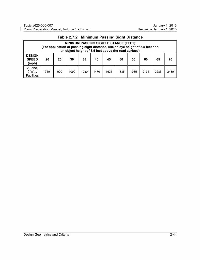
Topic #625-000-007 January 1, 2013 Plans Preparation Manual, Volume 1 - English Revised – January 1, 2015
Table 2.7.2 Minimum Passing Sight Distance MINIMUM PASSING SIGHT DISTANCE (FEET)
(For application of passing sight distance, use an eye height of 3.5 feet and an object height of 3.5 feet above the road surface)
DESIGN SPEED (mph)
20 25 30 35 40 45 50 55 60 65 70
2-Lane, 2-Way
Facilities 710 900 1090 1280 1470 1625 1835 1985 2135 2285 2480
Design Geometrics and Criteria 2-44

Topic #625-000-007 January 1, 2013 Plans Preparation Manual, Volume 1 - English Revised – January 1, 2015
2.8 Curves
2.8.1 Horizontal Curves
Design speed is the principal factor controlling horizontal alignment. Several geometric standards related to design speed are very specific. Other criteria cannot be defined as specifically and require that judgments be made by designers in consideration of local conditions.
2.8.1.1 Supplemental Alignment Control (Mainline)
On projects which include roadways and bridges, coordination between the Roadway and Structures Design Offices may be necessary for those horizontal alignment issues affecting the location or geometry of the structure(s).
Avoid placing horizontal curves, PI’s and superelevation transitions within the limits of a structure or approach slabs wherever practical. Because of the impact on the structure framing, spiral curves or alignments that result in skews greater than 45 degrees should be avoided. When skews greater than 45 degrees and/or spirals are necessary, specific justification including alternate framing concepts that relieve the severe skew effect shall be submitted to the District Design Engineer for concurrence.
Placement of stationing equations within the limits of a structure should be avoided on contract plans. Such equations unnecessarily increase the probability of error in both the design and construction phase.
Further guidelines have been established by the Department for lengths of horizontal curves, maximum deflections without curves, redirection of through lanes at intersections and minimum transition lengths between reverse curves. The criteria given are intended for use in establishing minimum lengths for both rural and urban conditions. See Tables 2.8.1 – 2.8.4.
For small deflection angles (5° or less), curves shall be at least 500 ft. long and the minimum increased 100 ft. for each 1° decrease in the central angle (900 ft. for a 1° central angle).
Modification for Non-Conventional Projects:
Delete the last sentence in above paragraph.
Design Geometrics and Criteria 2-45

Topic #625-000-007 January 1, 2013 Plans Preparation Manual, Volume 1 - English Revised – January 1, 2015 For design, the aesthetic control given above should be considered where practical, but may be compromised where other considerations warrant such action. Discernment of alignment changes in an urban setting is normally minimal due to the masking effects of development, traffic signs, various items of interest and similar distracting stimuli.
For information on the maximum deflection without a curve, see Table 2.8.1.
When compound curves are necessary on open highways, the ratio of the flatter radius to the sharper radius shall not exceed 1.5:1. For turning roadways and intersections a ratio of 2:1 (where the flatter radius precedes the sharper radius in the direction of travel) is acceptable.
The length of compound curves for turning roadways when followed by a curve of one-half radius or preceded by a curve of double radius should be as shown in Table 2.8.2b.
Design Geometrics and Criteria 2-46

Topic #625-000-007 January 1, 2013 Plans Preparation Manual, Volume 1 - English Revised – January 1, 2015
Table 2.8.1a Maximum Deflections without Horizontal Curves MAXIMUM DEFLECTION WITHOUT CURVE (DMS)
TYPE FACILITY V ≥ 45 mph V ≤ 40 mph Freeways 0° 45' 00" N/A
Arterials and Collectors
Without Curb & Gutter 0° 45' 00" 2° 00' 00"
With Curb & Gutter 1° 00' 00" 2° 00' 00"
Where V=Design Speed (mph)
Table 2.8.1b Maximum Deflection for Through Lanes through Intersections
Design speed (mph) 20 25 30 35 40 45
Maximum Deflection 16° 00' 11° 00' 8° 00' 6° 00' 5° 00' 3° 00'
Design Geometrics and Criteria 2-47

Topic #625-000-007 January 1, 2013 Plans Preparation Manual, Volume 1 - English Revised – January 1, 2015
Table 2.8.2a Length of Horizontal Curves LENGTH OF CURVE (FEET)
Freeways 30V 1
Arterials 15V 2 Collectors 15V 2
Where V = Design Speed (mph) 1. When 30V cannot be attained, the greatest attainable length shall
be used, but not less than 15V.
2. When 15V cannot be attained, the greatest attainable length shall be used, but not less than 400ft.
Curve length shall provide full superelevation within the curve of not less than 200 ft. (Rural) or 100 ft. (Urban)
Table 2.8.2b Arc Length (in feet) of Compound Curves with One-Half/Double Radii - Turning Roadways
Radius (ft.) 100 150 200 250 300 400 ≥ 500
Minimum Length 40 50 65 85 100 120 150 Desirable Length 65 70 100 120 150 180 200
Design Geometrics and Criteria 2-48
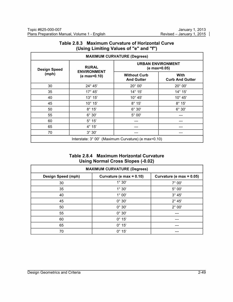
Topic #625-000-007 January 1, 2013 Plans Preparation Manual, Volume 1 - English Revised – January 1, 2015
Table 2.8.3 Maximum Curvature of Horizontal Curve (Using Limiting Values of "e" and "f")
MAXIMUM CURVATURE (Degrees)
Design Speed (mph)
RURAL ENVIRONMENT
(e max=0.10)
URBAN ENVIRONMENT (e max=0.05)
Without Curb And Gutter
With Curb And Gutter
30 24° 45' 20° 00' 20° 00' 35 17° 45' 14° 15' 14° 15' 40 13° 15' 10° 45' 10° 45' 45 10° 15' 8° 15' 8° 15' 50 8° 15' 6° 30' 6° 30' 55 6° 30' 5° 00' --- 60 5° 15' --- --- 65 4° 15' --- --- 70 3° 30' --- ---
Interstate: 3° 00' (Maximum Curvature) (e max=0.10)
Table 2.8.4 Maximum Horizontal Curvature Using Normal Cross Slopes (-0.02)
MAXIMUM CURVATURE (Degrees)
Design Speed (mph) Curvature (e max = 0.10) Curvature (e max = 0.05) 30 1° 30' 7° 00' 35 1° 30' 5° 00' 40 1° 00' 3° 45' 45 0° 30' 2° 45' 50 0° 30' 2° 00' 55 0° 30' --- 60 0° 15' --- 65 0° 15' --- 70 0° 15' ---
Design Geometrics and Criteria 2-49

Topic #625-000-007 January 1, 2013 Plans Preparation Manual, Volume 1 - English Revised – January 1, 2015
2.8.1.2 Supplemental Alignment Control (Intersections)
For redirection or offset deflection of through lanes through intersections, see the values given in Table 2.8.1b. Curves are not required for these angular breaks.
2.8.1.3 Roadway Transitions
Transition details have been developed and included in the Design Standards. Transitions on curved alignment will require special design details in the contract plans.
Design Geometrics and Criteria 2-50

Topic #625-000-007 January 1, 2013 Plans Preparation Manual, Volume 1 - English Revised – January 1, 2015
2.8.2 Vertical Curves
Minimum lengths for crest and sag vertical curves are provided in Tables 2.8.5 – 2.8.6. K values for crest vertical curves are based on an eye height of 3.5' and an object height of 6".
Table 2.8.5 Minimum Lengths of Crest Vertical Curves Based on Stopping Sight Distance
K VALUES FOR CREST CURVES Design Speed (mph)
Interstate All Other Facilities
15 ---- 5 20 ---- 10 25 ---- 19 30 ---- 31 35 ---- 47 40 ---- 70 45 ---- 98 50 ---- 136 55 245 185 60 313 245 65 401 313 70 506 401
Length, L = KA Where: L = Minimum Length (feet) K = Constant A = Algebraic Difference In Grades (percent)
K values for crest vertical curves are based on an eye height of 3.5' and an object height of 6".
Interstates: Lengths of crest vertical curves on Interstate mainlines are not to be less than 1000 ft. for open highways and 1800 ft. within interchanges.
Service Interchanges: K values for ramp crest vertical curves at interstate terminals are not to be less than the Interstate K values. K values for other ramp crest vertical curves are not to be less than the K values for All Other Facilities.
System Interchanges: K values for all crest vertical curves on systems interchanges are not to be less than the K values of the higher system.
Arterials and Collectors: The minimum lengths of crest vertical curves for highways with design speeds of 50 mph or greater are as follows:
Design Speed (mph) 50 55 60 65 70 Minimum Length (ft.) 300 350 400 450 500 Low Speed Facilities: The lengths of crest vertical curves are not to be less than 3 times the
design speed (mph) expressed in feet.
Design Geometrics and Criteria 2-51

Topic #625-000-007 January 1, 2013 Plans Preparation Manual, Volume 1 - English Revised – January 1, 2015
Table 2.8.6 Minimum Lengths of Sag Vertical Curves Based on Stopping Sight Distance and Headlight Sight Distance
K VALUES FOR SAG CURVES
Design Speed (mph)
Interstate All Other Facilities
15 ---- 10 20 ---- 17 25 ---- 26 30 ---- 37 35 ---- 49 40 ---- 64 45 ---- 79 50 ---- 96 55 136 115 60 157 136 65 181 157 70 206 181
Length, L = KA Where: L = Minimum Length (feet) K = Constant A = Algebraic Difference In Grades (percent)
Interstates: Lengths of sag vertical curves on Interstate mainlines are not to be less than 800 ft.
Service Interchanges: K values for ramp sag vertical curves at interstate terminals are not to be less than the interstate K values. K values for other ramp sag vertical curves are not to be less than the K values for All Other Facilities.
System Interchanges: K values for all sag vertical curves on systems interchanges are not to be less than the K values of the higher system.
Arterials and Collectors: The minimum lengths of sag vertical curves for highways with design speeds of 50 mph or greater are as follows:
Design Speed (mph) 50 55 60 65 70 Minimum Length (ft.) 200 250 300 350 400
Low Speed Facilities: The lengths of sag vertical curves are not to be less than 3 times the design speed (mph) expressed in feet.
Design Geometrics and Criteria 2-52

Topic #625-000-007 January 1, 2013 Plans Preparation Manual, Volume 1 - English Revised – January 1, 2015
2.9 Superelevation
Superelevation rates of 0.10 maximum (rural) and 0.05 maximum (urban) are used by the Department on the State Highway System. Charts for these rates are in the criteria tables and figures. Additional data is contained in the Design Standards, Indexes 510 and 511.
The standard superelevation transition places 80% of the transition on the tangent and 20% on the curve. In transition sections where the cross slope is less than 1.5 %, a minimum longitudinal grade of 0.5% shall be maintained, unless the outside edge of pavement maintains a minimum grade of 0.2% (0.5% for curb and gutter).
When superelevation is required for curves in opposite directions on a common tangent, a suitable distance is required between the curves. This suitable tangent length should be determined as follows: 1. 80% of the transition for each curve should be located on the tangent. 2. The suitable tangent length is the sum of the two 80% distances, or greater. 3. Where alignment constraints dictate a less than desirable tangent length
between curves, an adjustment of the 80/20 superelevation transition treatment is allowed (where up to 50% of the transition may be placed on the curve).
Design Geometrics and Criteria 2-53

Topic #625-000-007 January 1, 2013 Plans Preparation Manual, Volume 1 - English Revised – January 1, 2015
Table 2.9.1 Superelevation Rates for Rural Highways, Urban Freeways and High Speed Urban Highways (e max =0.10)
TABULATED VALUES Degree of Curve D
Radius R (ft.)
DESIGN SPEED (mph) 30 35 40 45 50 55 60 65 70
0° 15' 22,918 NC NC NC NC NC NC NC NC NC 0° 30' 11,459 NC NC NC NC NC NC RC RC RC 0° 45' 7,639 NC NC NC NC RC RC 0.023 0.025 0.028 1° 00' 5,730 NC NC NC RC 0.021 0.025 0.030 0.033 0.037 1° 15' 4,584 NC NC RC 0.022 0.026 0.031 0.036 0.041 0.046 1° 30' 3,820 NC RC 0.021 0.026 0.031 0.037 0.043 0.048 0.054
*RNC
2° 00' RC 0.022 0.028 0.034 0.040 0.048 0.055 0.062 0.070 2,865
*RRC
2° 30' 0.021 0.028 0.034 0.041 0.049 0.058 0.067 0.075 0.085 2,292 3° 00' 1,910 0.025 0.032 0.040 0.049 0.057 0.067 0.077 0.087 0.096 3° 30' 1,637 0.029 0.037 0.046 0.055 0.065 0.075 0.086 0.095 0.100 4° 00' 1,432 0.033 0.042 0.051 0.061 0.072 0.083 0.093 0.099 Dmax =
3° 30' 5° 00' 1,146 0.040 0.050 0.061 0.072 0.083 0.094 0.098 Dmax = 4° 15' 6° 00' 955 0.046 0.058 0.070 0.082 0.092 0.099 Dmax =
5° 15'
7° 00' 819 0.053 0.065 0.078 0.089 0.098 Dmax = 6° 30'
8° 00' 716 0.058 0.071 0.084 0.095 0.100 9° 00' 637 0.063 0.077 0.089 0.098 Dmax =
8° 15'
10° 00' 573 0.068 0.082 0.094 0.100 11° 00' 521 0.072 0.086 0.097 Dmax =
10° 15'
12° 00' 477 0.076 0.090 0.099 13° 00' 441 0.080 0.093 0.100 14° 00' 409 0.083 0.096 Dmax =
13° 15' 15° 00' 382 0.086 0.098 16° 00' 358 0.089 0.099 18° 00' 318 0.093 Dmax =
17° 45'
20° 00' 286 0.097 22° 00' 260 0.099
24° 00' 239 0.100
Dmax = 24° 45'
* NC/RC and RC/e Break Points (Radius in feet)
Break Points DESIGN SPEED (mph) 30 35 40 45 50 55 60 65 70
RNC 3349 4384 5560 6878 8337 9949 11709 13164 14714
RRC 2471 3238 4110 5087 6171 7372 8686 9783 10955
e = NC if R ≥ RNC e = RC if R < RNC and R ≥ RRC
NC = Normal Crown ( -0.02 ) RC = Reverse Crown ( +0.02 ) RNC = Minimum Radius for NC RRC = Minimum Radius for RC
Rates for intermediate D's and R's are to be interpolated
Design Geometrics and Criteria 2-54

Topic #625-000-007 January 1, 2013 Plans Preparation Manual, Volume 1 - English Revised – January 1, 2015
Figure 2.9.1 Superelevation Rate For Rural Highways, Urban Freeways and High Speed Urban Highways (e max =0.10)
Design Geometrics and Criteria 2-55

Topic #625-000-007 January 1, 2013 Plans Preparation Manual, Volume 1 - English Revised – January 1, 2015
Table 2.9.2 Superelevation Rates for Urban Highways and High Speed Urban Streets (emax = 0.05)
TABULATED VALUES Degree of
Curve D
Radius R
(ft.)
DESIGN SPEED (mph) 30 35 40 45 50
2° 00' 2,865 NC NC NC NC NC 2° 15' 2,546 RC 2° 45' 2,083 NC 3° 00' 1,910 RC 3° 45' 1,528 NC 4° 00' 1,432 RC 4° 45' 1,206 RC 5° 00' 1,146 NC 0.023 5° 15' 1,091 RC 0.027 5° 30' 1,042 0.030 5° 45' 996 0.035 6° 00' 955 RC 0.040 6° 15' 917 0.022 0.045 6° 30' 881 0.024 0.050 6° 45' 849 0.027 Dmax =
6° 30' 7° 00' 819 NC 0.030 7° 15' 790 RC 0.033 7° 30' 764 0.037 7° 45' 739 0.041 8° 00' 716 RC 0.045 8° 15' 694 0.022 0.050 8° 30' 674 0.025 Dmax =
8° 15'
8° 45' 655 0.027 9° 00' 637 0.030 9° 30' 603 0.034 10° 00' 573 0.040 10° 30' 546 RC 0.047 11° 00' 521 0.023 Dmax =
10° 45'
11° 30' 498 0.026 12° 00' 477 0.030 13° 00' 441 0.036 14° 00' 409 RC 0.045 15° 00' 382 0.023 Dmax =
14° 15'
16° 00' 358 0.027 17° 00' 337 0.032 18° 00' 318 0.038 19° 00' 302 0.043 20° 00' 286 0.050
Dmax = 20° 00'
NC = Normal Crown ( -0.02 ) RC = Reverse Crown ( +0.02 )
Design Geometrics and Criteria 2-56

Topic #625-000-007 January 1, 2013 Plans Preparation Manual, Volume 1 - English Revised – January 1, 2015 Figure 2.9.2 Superelevation Rates for Urban Highways and High Speed Urban
Streets (emax = 0.05)
a. When the speed curves and the degree of curve lines intersect
above this line, the pavement is to be superelevated (positive slope) at the rates indicated at the lines intersecting points.
b. When the speed curves and the degree of curve lines intersect between these limits, the pavement is to be superelevated at the rate of 0.02 (positive slope).
c. When the speed curves and the degree of curve lines intersect below this line, the pavement is to have normal crown (typically 0.02 and 0.03 downward slopes).
Design Geometrics and Criteria 2-57

Topic #625-000-007 January 1, 2013 Plans Preparation Manual, Volume 1 - English Revised – January 1, 2015
Table 2.9.3 Superelevation Transition Slope Rates for Rural Highways, Urban Freeways and High Speed Urban Highways
SLOPE RATES FOR STRAIGHT LINE SUPERELEVATION TRANSITIONS
SECTION Design Speed (mph)
35-40 45-50 55-60 65-70
SLOPE RATES
2 Lane & 4 Lane 1:175 1:200 1:225 1:250
6 Lane --- 1:160 1:180 1:200
8 Lane --- 1:150 1:170 1:190
The length of superelevation transition is to be determined by the relative slope rate between the travel way edge of pavement and the profile grade, except that the minimum length of transition shall be 100 feet. For additional information on transitions, see the Design Standards, Index 510.
Table 2.9.4 Superelevation Transition Slope Rates for Urban Highways and High Speed Urban Streets
SLOPE RATES FOR STRAIGHT LINE SUPERELEVATION TRANSITIONS
30 mph 1:100
40 mph 1:125
45-50 mph 1 1:150
1. A slope rate of 1:125 may be used for 45 mph under restricted conditions. The length of superelevation transition is to be determined by the relative slope rate between the travel way edge of pavement and the profile grade, except that the minimum length of transition shall be 50 ft. for design speeds under 40 mph and 75 ft. for design speeds of 40 mph or greater. For additional information on transitions, see the Design Standards, Index 511.
Design Geometrics and Criteria 2-58

Topic #625-000-007 January 1, 2013 Plans Preparation Manual, Volume 1 - English Revised – January 1, 2015
2.10 Vertical Clearance
Minimum vertical clearances, with the exception of structures over water (see Section 2.10.1), are contained in the criteria tables and figures. On rural Interstate routes or single Interstate routes through urban areas, approved Design Exceptions are required for bridge vertical clearances less than 16 feet and must be coordinated with Surface Deployment and Distribution Command Transportation Engineering Agency (SDDCTEA) as described in Section 23.3. For bridges, sign structures and signal structures, minimum vertical clearance is the least distance measured between the bridge superstructure, signs, signals, luminaires or support members and the traffic lane or shoulder directly below.
For any construction affecting existing bridge clearances (e.g., bridge widenings or resurfacing) vertical clearances less than 16'-0" shall be maintained or increased. If reducing the design vertical bridge clearance to a value between 16’-0” and 16'-2", the design vertical clearance dimension in the plans shall be stated as a minimum with a note requiring the contractor to submit a certified survey confirming the as-built least vertical clearance is greater than the design vertical clearance.
For any construction affecting existing signs, vertical clearances less than 17'-0" shall be maintained or increased. For any construction affecting existing Dynamic Message Sign (DMS) structure clearances, all vertical clearances shall be maintained or increased.
For any construction affecting existing sign or signal clearances, existing vertical clearances less than 17'-0" shall not be reduced. For existing signalized intersections, if the vertical clearance is greater than or equal to 15’-0”, the existing signals shall remain; otherwise, the existing signals shall be “warranted for replacement”. No Design Variation shall be approved to allow signal clearances less than 15’-0”. For any construction affecting existing Dynamic Message Sign (DMS) structure clearance, existing vertical clearance shall not be reduced.
Design Geometrics and Criteria 2-59

Topic #625-000-007 January 1, 2013 Plans Preparation Manual, Volume 1 - English Revised – January 1, 2015 Figure 2.10.1 Clearances – Rural and Urban Interstates (Freeways), Arterials and
Collectors, with Projected 20-Year ADT of 1500 or Greater
Design Geometrics and Criteria 2-60

Topic #625-000-007 January 1, 2013 Plans Preparation Manual, Volume 1 - English Revised – January 1, 2015 Figure 2.10.2 Clearances – Rural Arterials and Collectors with Projected 20-Year
ADT of Less than 1500
Design Geometrics and Criteria 2-61

Topic #625-000-007 January 1, 2013 Plans Preparation Manual, Volume 1 - English Revised – January 1, 2015
Figure 2.10.3 Clearances – Urban Arterials and Collectors (Without Curb and Gutter) with Projected 20-Year ADT of Less than 1500
Design Geometrics and Criteria 2-62

Topic #625-000-007 January 1, 2013 Plans Preparation Manual, Volume 1 - English Revised – January 1, 2015
Figure 2.10.4.A Clearances – Urban Arterials and Collectors (Curb and Gutter) ≤ 45 mph – Elevation of Bridge
Design Geometrics and Criteria 2-63

Topic #625-000-007 January 1, 2013 Plans Preparation Manual, Volume 1 - English Revised – January 1, 2015 Figure 2.10.4.B Clearances – Urban Arterials and Collectors (Curb and Gutter)
≤ 45 mph – Section through Bridge
Design Geometrics and Criteria 2-64
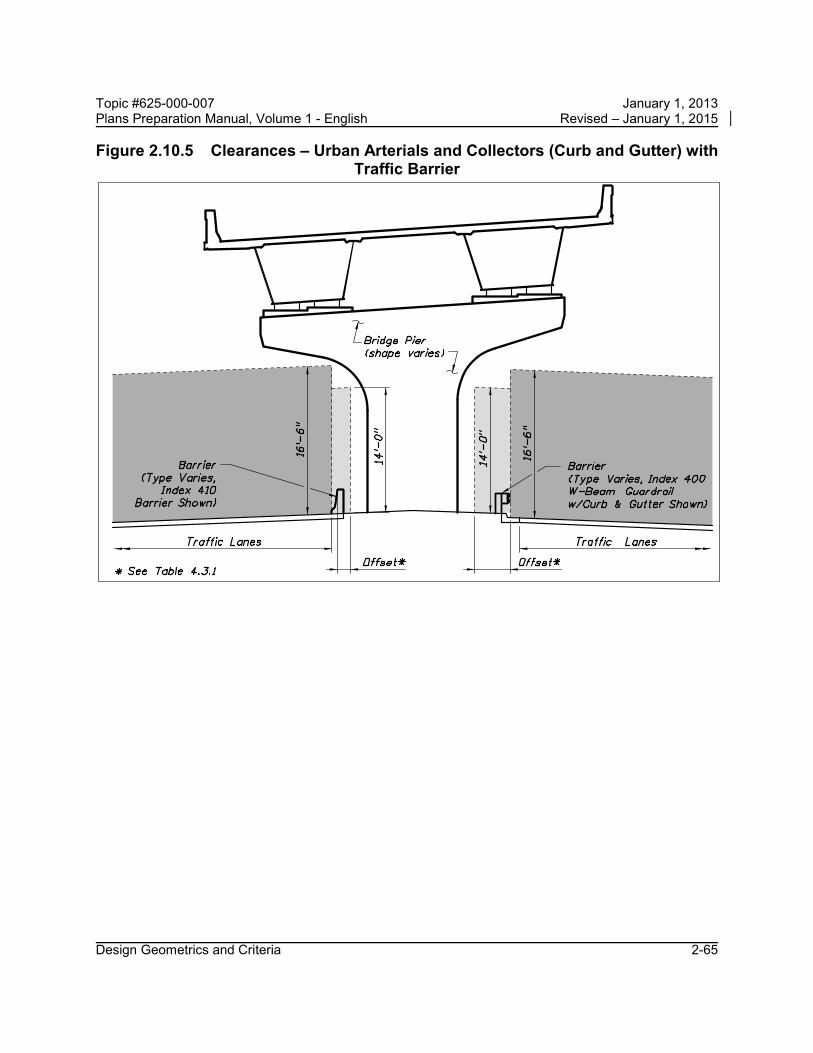
Topic #625-000-007 January 1, 2013 Plans Preparation Manual, Volume 1 - English Revised – January 1, 2015 Figure 2.10.5 Clearances – Urban Arterials and Collectors (Curb and Gutter) with
Traffic Barrier
Design Geometrics and Criteria 2-65

Topic #625-000-007 January 1, 2013 Plans Preparation Manual, Volume 1 - English Revised – January 1, 2015
Table 2.10.1 Minimum Vertical Clearances for New Bridges FACILITY TYPE (Freeways, Arterials, Collectors & Others) 1 CLEARANCE
Roadway or Railroad Over Roadway 16'-6"
Roadway Over Railroad 23’-6” 2
Pedestrian Over Roadway 17'-6"
Pedestrian Over Railroad 23'-6" 2
1. For Clearance Over Waterways, see Section 2.10.1 of this volume. 2. Over High Speed Rail Systems, see Section 6.3.5 of this volume and the latest version of
American Railway Engineering and Maintenance-of-Way Association (AREMA) guidelines, or the design office of the high speed rail line of interest for specific guidelines and specifications. Over Electrified Railroad, the minimum vertical clearance shall be 24 feet 3 inches. (See Topic No. 000-725-003: South Florida Rail Corridor Clearance.) Also see Section 6.3.5 of this volume.
Table 2.10.2 Minimum Vertical Clearances for New Sign and Signal Structures
TYPE OF STRUCTURE CLEARANCE
Overhead Sign Structures 17'-6"
Overhead Dynamic Message Sign Structures 19'-6"
Signals on Span Wires, Mast Arms, or Other Structures 17'-6"
Design Geometrics and Criteria 2-66

Topic #625-000-007 January 1, 2013 Plans Preparation Manual, Volume 1 - English Revised – January 1, 2015
2.10.1 Vertical Clearance Over Water
The minimum vertical clearance over water shall conform to the following criteria: 1. Environment:
For concrete superstructures classified as moderately aggressive or extremely aggressive due to chloride content, the minimum vertical clearance is 12 ft. above Mean High Water (MHW). For steel superstructures, the minimum vertical clearance shall be obtained from the District Bridge Maintenance Engineer, but shall not be less than those specified above for the concrete superstructures.
2. Drainage: The minimum vertical clearance between the design flood stage and the low member of bridges shall be a minimum of two feet. This clearance is necessary to allow the majority of debris to pass without causing damage to the structure. This standard does not apply to culverts and bridge-culverts.
3. Navigation: The minimum vertical clearance for navigational purposes shall be:
A. 6 feet above the Mean High Water for tidewater bays and streams
B. 6 feet above the Normal High Water for freshwater rivers, streams, non-regulated/controlled canals, and lakes
C. 6 feet above the control elevation for regulated/controlled lakes and canals
Minimal vertical at the navigable channel clearance is measured from the low point of the structural member of the bridge. Navigation lights shall not be considered in the vertical clearance.
Coastal bridges: The vertical clearance of the superstructure shall be a minimum of 1 ft. above the 100-year design wave crest elevation including the storm surge elevation and
Modification for Non-Conventional Projects:
Delete the above paragraph and replace with the following: For steel superstructures, the minimum vertical clearance shall not be less than those specified above for the concrete superstructures or as specified in the RFP.
Design Geometrics and Criteria 2-67
Topic #625-000-007 January 1, 2013 Plans Preparation Manual, Volume 1 - English Revised – January 1, 2015
wind setup. For bridge designs where this criterion cannot practically be met, refer to the FDOT Drainage Manual, Section 4.9.5.
Information on the Normal High Water, control water elevation, or Mean High Water can be obtained from the appropriate Drainage Design Engineer.
Widening of existing structures which do not meet the minimum vertical clearance criteria stated above (either before or after the widening) may be justified hydraulically and/or economically. However, the encroachment of vertical clearance criteria may be limited and must be approved by the agency having jurisdiction over the navigable waterway.
2.10.2 Horizontal Waterway Clearance
The following minimum horizontal clearances shall be provided:
1. For crossings subject to boat traffic a minimum horizontal clearance of 10 feet shall be provided.
2. Where no boat traffic is anticipated, horizontal clearance shall be provided consistent with debris conveyance needs and structure economy.
Horizontal clearance is defined as the unobstructed clear distance between piers, fender systems, culvert walls, etc. projected by the bridge normal to the flow.
2.10.3 Regulatory Agency Requirements
Vertical and horizontal clearances will also be subject to the requirements of the Coast Guard, Corps of Engineers, Water Management District, and any other regulatory agency having appropriate statutory jurisdiction or authority. Such regulatory agency requirements may exceed Department requirements.
Design Geometrics and Criteria 2-68

Topic #625-000-007 January 1, 2013 Plans Preparation Manual, Volume 1 - English Revised – January 1, 2015
2.10.4 Airspace Obstructions
Federal, state, and local regulations exist to protect the national airspace system that must be considered when planning and implementing construction that may adversely impact military or public-use aviation facilities (airport, seaport, or heliport), navigational aids, and instrument approach flight procedures in Florida.
FAA Notification: Federal law, Title 14 Code of Federal Regulations (CFR), Federal Aviation Regulations (FAR), Part 77, “Objects Affecting Navigable Airspace”, requires that prior notification must be given to the Federal Aviation Administration (FAA) regarding any construction or alteration (permanent or temporary) of structures that meet the specific criteria given in Table 2.10.3.
For further guidance on airspace obstructions (notification and permitting) refer to Section 13.5.1, FDOT Aviation and Spaceports Office Coordination, this volume.
Modification for Non-Conventional Projects:
See RFP for design build coordination of air space requirements.
Design Geometrics and Criteria 2-69

Topic #625-000-007 January 1, 2013 Plans Preparation Manual, Volume 1 - English Revised – January 1, 2015
Table 2.10.3 FAA Notification Requirements
FAA Notification Requirements for Construction or Alteration of Structures *
1. Any structure more than 200 feet above ground level (AGL) at its site.
2. Any structure that is near an aviation facility and that penetrates an imaginary obstacle surface extending outward and upward at one of the following criteria: a. A slope of 100 to 1 (1 foot upward for each 100 feet outward) for a horizontal
distance of 20,000 feet from the nearest point of the nearest military or public-use airport runway that is more than 3,200 feet in length (excludes heliports).
b. A slope of 50 to 1 (1 foot upward for each 50 feet outward) for a horizontal distance of 10,000 feet from the nearest point of the nearest military or public-use airport runway no more than 3,200 feet in length (excludes heliports).
c. A slope of 25 to 1 (1 foot upward for each 25 feet outward) for a horizontal distance of 5,000 feet from the nearest point of the nearest military or public-use heliport landing and takeoff area.
3. Any highway, railroad, or other traverse way for mobile objects, of a height which, if adjusted upward by the amount shown below, would exceed a standard of paragraph 1 or 2 above: a. An adjusted height of 17 feet for an Interstate Highway that is part of the
National System of Military and Interstate Highways where over-crossings are designed for a minimum of 17 feet vertical distance.
b. An adjusted height of 15 feet for any other public roadway. c. An adjusted height of 10 feet or the height of the highest mobile object that
would normally traverse the road, whichever is greater, for a private road. d. An adjusted height of 23 feet for a railroad. e. An adjusted height equal to the height of the highest mobile object that would
normally traverse it, for a waterway or traverse way not previously mentioned.
4. Any structure located directly on a public-use aviation facility property, including any facility that is currently existing, planned, proposed, or under construction.
5. Any structure that is located in an instrument approach area and available information indicates it might exceed federal obstruction standards, if specifically requested by the FAA.
* Note: Structures may include: Highways, roads, railroads, waterways, traverseways (parking or rest areas), bridges, overpasses, high-mast light poles, utility poles, antenna towers, buildings, signs or billboards, fences, or gates, plus temporary-use construction materials or equipment, including dirt piles and cranes, as well as natural growth, vegetation, and landscaping, depending on location in proximity to an aviation facility, navigational aid, or instrument procedure ground track.
Design Geometrics and Criteria 2-70

Topic #625-000-007 January 1, 2013 Plans Preparation Manual, Volume 1 - English Revised – January 1, 2015
2.11 Lateral Offset
Lateral offset is the lateral distance from a specified point on the roadway such as the edge of travel lane or face of curb, to a roadside feature or object. Lateral offset applies to all highways. Lateral offset requirements vary depending on design speed, whether rural or urban with curb, traffic volumes, lane type, and the object or feature.
Rural highways with flush shoulders and highways with curb or curb and gutter where right of way is not restricted have roadsides of sufficient widths to provide clear zones; therefore, lateral offset requirements for certain features and objects are based on maintaining a clear zone wide enough to provide the recoverable terrain in Table 2.11.11. The procedure for determining required clear zone widths is described in Chapter 4 of this volume.
In urban areas, lateral offset based on clear zone requirements for rural highways should be provided wherever practical. However, urban areas are typically characterized with lower speed (Design Speed ≤ 45 mph), more dense abutting development, closer spaced intersections and accesses to property, higher traffic volumes, more bicyclists and pedestrians, and restricted right of way. In these areas, curb with closed drainage systems are often used to minimize the amount of right of way needed. Highways with curb or curb and gutter in urban areas where right of way is restricted do not have roadsides of sufficient widths to provide clear zones; therefore, while there are specific lateral offset requirements for these highways, they are based on offsets for normal operation and not based on maintaining a clear roadside for errant vehicles. It should be noted that curb has no redirectional capabilities except at speeds less than the lowest design speeds used on the State Highway System. Therefore curb should not be considered effective in shielding a hazard. Curb is not to be used to reduce lateral offset requirements.
Crashworthy objects shall meet or exceed the offset listed in Tables 2.11.1 through 2.11.10 and objects that are not crashworthy are to be as close to the right of way line as practical and no closer than the requirements listed in Tables 2.11.1 through 2.11.10.
For lateral offsets where roadways overpass railroads refer to Chapter 6 of this volume.
Design Geometrics and Criteria 2-71

Topic #625-000-007 January 1, 2013 Plans Preparation Manual, Volume 1 - English Revised – January 1, 2015
Table 2.11.1 Lateral Offset for Traffic Control Signs
PLACEMENT
Placement shall be in accordance with the Design Standards. Placement within sidewalks shall be such that an unobstructed sidewalk width of 4 feet or more (not including the width of curb) is provided.
SUPPORTS
Supports, except overhead sign supports, shall be breakaway. When practicable, sign supports should be located behind barriers that are justified for other reasons. Overhead sign supports shall be located outside the clear zone unless shielded.
Table 2.11.2 Lateral Offset for Light Poles
CONVENTIONAL LIGHTING
Shall not be located in the median except in conjunction with barriers that are justified for other reasons. Supports shall be breakaway, except for median barrier mounted or shielded light poles. Urban Curb or Curb and Gutter (Design Speed ≤ 45 mph):
Shall be located no closer than 4 feet from face of curb. Placement within sidewalks shall be such that an unobstructed sidewalk width of 4 feet or more (not including the width of curb) is provided.
All other facilities: Shall be located no closer than 20 feet from the travel lane or 14 feet from an auxiliary lane (may be clear zone width when clear zone is less than 20 feet).
HIGHMAST LIGHTING
Shall be located outside the clear zone unless shielded.
Design Geometrics and Criteria 2-72

Topic #625-000-007 January 1, 2013 Plans Preparation Manual, Volume 1 - English Revised – January 1, 2015
Table 2.11.3 Lateral Offset for Aboveground Fixed Utilities (AFUs)
Aboveground fixed utilities are objects owned by a public or private utility agency that are more than four (4) inches above the grade and are not accepted by FDOT as crashworthy (such as strain poles, down guys, telephone load pedestals, temporary supports, etc.).
NEW ABOVEGROUND FIXED UTILITIES
(AFUs)
Other than mid-span poles
For urban roadways with curb or curb and gutter with design speeds less than or equal to 45 mph, new AFUs shall not be placed closer than 4 feet from the face of curb and as close to the R/W as practical. For all other roadways the AFUs are to be outside the Clear Zones established using Table 2.11.11 Recoverable Terrain and as close to the R/W line as practical.
NEW ABOVEGROUND FIXED UTILITIES
(AFUs)
Mid-span poles
Mid-span poles are new poles being installed as part of and within the alignment of an existing pole line. When the existing alignment crosses an intersecting roadway, the mid-span pole is to be placed as follows: For intersecting roadways that are urban with curb or curb and gutter with design speeds less than or equal to 45 mph, mid-span poles shall not be placed closer than 4 feet from the face of curb. For all other intersecting roadways mid-span poles are to be outside the Clear Zones established for new poles appropriate for the intersecting roadway.
EXISTING ABOVEGROUND FIXED UTILITIES
(AFUs)
For urban roadways with curb or curb and gutter with design speeds less than or equal to 45 mph, existing AFUs closer than 4 feet from the face of curb shall be relocated as close to the R/W line as practical. For all other roadways, existing AFUs within the Clear Zones established using Table 2.11.11 Recoverable Terrain shall be relocated as close to the R/W line as practical.
Design Geometrics and Criteria 2-73

Topic #625-000-007 January 1, 2013 Plans Preparation Manual, Volume 1 - English Revised – January 1, 2015
Table 2.11.4 Lateral Offset to Traffic Infraction Detectors, Signal Poles and Controller Cabinets for Signals
SIGNAL POLES
AND
CONTROLLER CABINETS
Shall not be located in medians
Shall be located outside the clear zone except as follows: Urban Curb or Curb and Gutter (Design Speed ≤ 45 mph): Shall be located no closer than 4 feet from face of outside curbs and
outside the sidewalk. However, when necessary, signal poles may be located within sidewalks such that an unobstructed sidewalk width of 4 feet or more (not including the width of curb) is provided.
TRAFFIC INFRACTION DETECTORS
For Traffic Infraction Detector placement and installation specifications, refer to the State Traffic Engineering and Operations Office web page:
http://www.dot.state.fl.us/trafficoperations/
Table 2.11.5 Lateral Offset to Trees
Trees, where the diameter is or is expected to be greater than 4 inches (measured 6 inches above the ground), must be located outside the clear zone, except:
• Roadways with Curb and Gutter where Design Speed ≤ 45 mph, the tree must be at least 4 feet from face of the curb.
Design Geometrics and Criteria 2-74

Topic #625-000-007 January 1, 2013 Plans Preparation Manual, Volume 1 - English Revised – January 1, 2015
Table 2.11.6 Lateral Offset to Bridge Piers and Abutments
Bridge Piers and Abutments shall be located outside the clear zone (see also Figures 2.10.1 thru 2.10.3) except as follows: Urban Curb or Curb and Gutter (Design Speed ≤ 45 mph), shall be located no closer than:
• 16 feet from the edge of the travel lane; or • 4 feet from face of outside curbs or • 6 feet from the edge of inside traffic lane:
whichever provides the greater setback. See also Figures 2.10.4.A thru 2.10.4.B. Rural and Urban with Roadside Barriers: The minimum barrier offset as shown in Table 4.3.1 measured from the face of the barrier.
See also Figure 2.10.5.
Notes: 1. Pier protection and design shall comply with the requirements provided in Structures Design Guidelines, Section 2.6.
2. Locate piers outside of offset envelopes as shown. Additional offsets may be required for sidewalks, shared use paths, intersection sight distance and future widening of the lower roadway.
3. Evaluate the potential for widening of a lower roadway at a given location based on adjacent geometric constraints, (e.g. other bridge piers, MSE walls, significant water features, etc.).
Design Geometrics and Criteria 2-75

Topic #625-000-007 January 1, 2013 Plans Preparation Manual, Volume 1 - English Revised – January 1, 2015
Table 2.11.7 Lateral Offset to Railroad Grade Crossing Traffic Control Devices
Shall be located in accordance with the Design Standards.
Table 2.11.8 Lateral Offset to Canal and Drop-off Hazards
See Chapter 4 of this Volume for lateral offset criteria for canal and drop-off hazards.
Table 2.11.9 Lateral Offset to Other Roadside Obstacles
Shall be located outside the clear zone except as follows:
Urban Curb or Curb and Gutter (Design Speed ≤ 45 mph): Shall be located no closer than 4 feet from face of curb.
Note: Lateral offset to mailboxes is specified in the construction details contained in the Design Standards, Index No. 532.
Note: Transit and school bus shelters shall be placed in accordance with Rule Chapter 14-20.003, Florida Administrative Code. Transit bus benches shall be located in accordance with Rule Chapter 14-20.0032, F.A.C..
Design Geometrics and Criteria 2-76

Topic #625-000-007 January 1, 2013 Plans Preparation Manual, Volume 1 - English Revised – January 1, 2015
Table 2.11.10 Lateral Offset for ITS Poles and Related Items
POLES AND OTHER ABOVE-GROUND FIXED OBJECTS
Shall not be located in the median except in conjunction with barriers that are justified for other reasons. Shall be located outside the clear zone (as close as practical to the right of way line without aerial encroachments onto private property) except as follows:
Urban Curb or Curb and Gutter (Design Speed ≤ 45 mph): Shall be located as close to the right of way line as practical; no closer than 4 feet from face of curb. Placement within sidewalks shall be such that an unobstructed sidewalk width of 4 feet or more (not including the width of curb) is provided.
May be located behind barriers that are justified for other reasons.
EQUIPMENT SHELTERS AND TOWERS
Shall not be located within the limited-access right of way, except as allowed by Policy No. 000-625-025, Telecommunications Facilities on Limited Access Rights of Way.
BREAKAWAY OBJECTS
Shall be located as close to the right of way line as practical, except as follows: Urban Curb or Curb and Gutter (Design Speed ≤ 45 mph):
Shall be located no closer than 4 feet from the face of curb.
Design Geometrics and Criteria 2-77

Topic #625-000-007 January 1, 2013 Plans Preparation Manual, Volume 1 - English Revised – January 1, 2015
Table 2.11.11 Recoverable Terrain
DESIGN SPEED (mph)
≥ 1500 AADT(1)
< 1500 AADT(1)
TRAVEL LANES
& MULTILANE
RAMPS (feet)
AUXILIARY LANES
& SINGLE LANE
RAMPS (feet)
TRAVEL LANES
& MULTILANE
RAMPS (feet)
AUXILIARY LANES
& SINGLE LANE
RAMPS (feet)
< 45
18
10
16
10
45
24
14
20
14
50
24
14
20
14
55
30
18
24
14
> 55
36
24
30
18
(1) AADT=Mainline 20 years projected annual average daily traffic. The above values are to be used in the process for determining the clear zone width as described in Chapter 4 of this volume.
Design Geometrics and Criteria 2-78

Topic #625-000-007 January 1, 2013 Plans Preparation Manual, Volume 1 - English Revised – January 1, 2015
Figure 2.11.1 Lateral Offset to Guardrail
Design Geometrics and Criteria 2-79

Topic #625-000-007 January 1, 2013 Plans Preparation Manual, Volume 1 - English Revised – January 1, 2015
2.12 Bridge Railings and Separators
Bridge railings and separators on new and reconstruction projects shall be designed in accordance with the Structures Design Guidelines. On reconstruction projects, where an existing bridge is to remain, existing bridge railings must be replaced or upgraded unless the railing meets criteria for new railings. All superseded FDOT Standard New Jersey Shape and F Shape Traffic Railings conforming to the designs shown in the Instructions for Design Standards, Index 402, “A Historical Compilation of Superseded Florida Department of Transportation ‘Structures Standard Drawings’ for ‘F’ and ‘New Jersey’ Shape Structure Mounted Traffic Railings", are both structurally and functionally adequate.
All other former FDOT bridge traffic railings not listed above, and any other traffic railings that are not based on crash tested designs, are inadequate and shall be replaced, retrofitted or excepted, as appropriate, using the criteria included in the Structures Design Guidelines.
Details and typical applications of various bridge rails and separators are given in Figures 2.12.1 – 2.12.12.
Design Geometrics and Criteria 2-80

Topic #625-000-007 January 1, 2013 Plans Preparation Manual, Volume 1 - English Revised – January 1, 2015
Figure 2.12.1 Bridge Traffic Railings – "F" Shapes
Design Geometrics and Criteria 2-81

Topic #625-000-007 January 1, 2013 Plans Preparation Manual, Volume 1 - English Revised – January 1, 2015
Figure 2.12.2 Bridge Traffic Railings – Vertical Shapes
Design Geometrics and Criteria 2-82

Topic #625-000-007 January 1, 2013 Plans Preparation Manual, Volume 1 - English Revised – January 1, 2015
Figure 2.12.3 Bridge Traffic Railings – Other Shapes
Design Geometrics and Criteria 2-83

Topic #625-000-007 January 1, 2013 Plans Preparation Manual, Volume 1 - English Revised – January 1, 2015
Figure 2.12.4 Bridge Traffic Railings – Noise Barrier Combination
Design Geometrics and Criteria 2-84

Topic #625-000-007 January 1, 2013 Plans Preparation Manual, Volume 1 - English Revised – January 1, 2015 Figure 2.12.5 Bridge Railing and Separators – Median Traffic Railing and
Separators
Design Geometrics and Criteria 2-85

Topic #625-000-007 January 1, 2013 Plans Preparation Manual, Volume 1 - English Revised – January 1, 2015
Figure 2.12.6 Bridge Fencing for Traffic Railings
Design Geometrics and Criteria 2-86

Topic #625-000-007 January 1, 2013 Plans Preparation Manual, Volume 1 - English Revised – January 1, 2015
Figure 2.12.7 Bridge Railing – Pedestrian / Bicycle Railing
Design Geometrics and Criteria 2-87
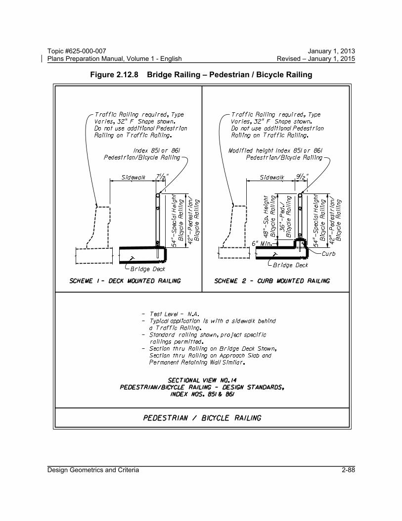
Topic #625-000-007 January 1, 2013 Plans Preparation Manual, Volume 1 - English Revised – January 1, 2015
Design Geometrics and Criteria 2-88
Figure 2.12.8 Bridge Railing – Pedestrian / Bicycle Railing
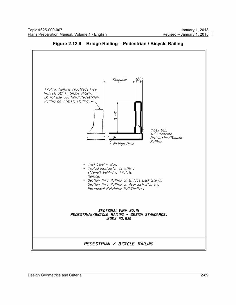
Topic #625-000-007 January 1, 2013 Plans Preparation Manual, Volume 1 - English Revised – January 1, 2015
Figure 2.12.9 Bridge Railing – Pedestrian / Bicycle Railing
Design Geometrics and Criteria 2-89
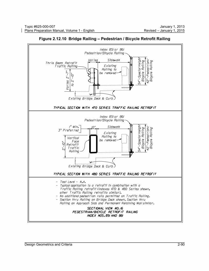
Topic #625-000-007 January 1, 2013 Plans Preparation Manual, Volume 1 - English Revised – January 1, 2015
Figure 2.12.10 Bridge Railing – Pedestrian / Bicycle Retrofit Railing
Design Geometrics and Criteria 2-90

Topic #625-000-007 January 1, 2013 Plans Preparation Manual, Volume 1 - English Revised – January 1, 2015
Design Geometrics and Criteria 2-91
Figure 2.12.11 Bridge Fencing for Pedestrian Railing

Topic #625-000-007 January 1, 2013 Plans Preparation Manual, Volume 1 - English Revised – January 1, 2015
Design Geometrics and Criteria 2-92
Figure 2.12.12 Enclosed Bridge Fencing for Pedestrian Railing

Topic #625-000-007 January 1, 2013 Plans Preparation Manual, Volume 1 - English Revised – January 1, 2015
2.13 Intersections
Design guides and criteria presented heretofore are also applicable to the proper design of intersections.
2.13.1 Roundabouts
The National Cooperative Highway Research Program (NCHRP) Report 672, Roundabouts: An Informational Guide, is adopted by FHWA and establishes criteria and procedures for the justification, operational and safety analysis of modern roundabouts in the United States. In addition, the Florida Intersection Design Guide contains Florida centric guidelines and requirements for evaluation and design of roundabouts in Florida.
Roundabouts must be evaluated on new construction, reconstruction and safety improvement projects, as well as any time there are proposed changes in intersection control that will require new signalization or replacement of existing signals. An evaluation is not required for minor operational improvements such as modifications to signal phasing or addition of turn lanes.
Modification for Non-Conventional Projects:
Delete the last sentence and see the RFP for requirements.
2.13.2 Queue Length for Unsignalized Intersections
Turn lanes should comply with the Design Standards, Index 301 to the extent practical. The available queue length provided should be based on a traffic study.
For low volume intersections where a traffic study is not justified, a minimum queue length of 50 ft. (2 vehicles) should be provided for rural areas and small urban areas; for other urban areas, a minimum queue length of 100 ft. (4 vehicles) should be provided.
Design Geometrics and Criteria 2-93

Topic #625-000-007 January 1, 2013 Plans Preparation Manual, Volume 1 - English Revised – January 1, 2015
2.13.3 Offset Left Turn Lanes
The alignment of opposing left-turn lanes and the horizontal and vertical curvature on the approaches are the principal geometric design elements that determine how much sight distance is available to a left-turning driver. Operationally, vehicles in the opposing left-turn lane waiting to turn left can also restrict the left-turning driver’s view of oncoming traffic in the through lanes. The level of blockage depends on how the opposing left-turn lanes are aligned with respect to each other, as well as the type/size of vehicles in the opposing queue and their position in the opposing lane.
The offset distance is defined as the distance between the left edge of the turn lane and the right edge of the opposing turn lane. If the offset distance is to the left of the turn lane it is considered a negative offset, and if it is to the right of turn lane it is considered a positive offset.
The conventional method of designing left turn lanes is to place the left turn lanes adjacent to the through lanes. This design creates a negative offset which severely restricts the sight distance of the left-turning driver’s view of oncoming traffic when another vehicle is in the opposing turn lane. Figure 2.13.1 indicates the negative offset when the conventional design is used.
Figure 2.13.1 Typical Opposing Left Turns (22’ Median with Negative 10’ Offset)
On all urban designs offset left-turn lanes should be used with median widths greater than 18 feet. A four foot traffic separator should be used when possible to channelize the left turn and provide separation from opposing traffic. On rural intersections where high turning movements are involved, offset left-turn lanes should also be considered. On median widths 30 feet or less, an offset turn lane parallel to the through lane should be used and the area between the left turn and traffic lane where vehicles are moving in the same direction should be striped out. On medians greater than 30 feet, a tapered offset should be considered. AASHTO Exhibit 9-98 illustrates the design of parallel and tapered left turn lanes. Figure 2.13.2 indicates an offset left turn.
Design Geometrics and Criteria 2-94

Topic #625-000-007 January 1, 2013 Plans Preparation Manual, Volume 1 - English Revised – January 1, 2015
Figure 2.13.2 Typical Opposing Left Turns (22’ Median with Negative 1’ Offset)
As illustrated in Figure 2.13.2, the sight distance is improved significantly by utilizing the offset left turn design even when a positive offset is not achieved. The graph in Figure 2.13.3 is taken from the Older Driver Highway Design Handbook, and gives the left turn offset guidelines that may be considered for various design speeds and vehicle types.
Figure 2.13.3 Left Turn Offset Guidelines
0
1
2
3
4
5
6
20 25 30 35 40 45 50 55 60 65 70
Left-
Turn
Lan
e O
ffset
(ft)
Major Road Design Speed (mi/h)
Modified AASHTO - Car
Modified AASHTO - Truck
Unrestricted - Car
Unrestricted - Truck
Model - Opposing Vehicle
Design Geometrics and Criteria 2-95
Topic #625-000-007 January 1, 2013 Plans Preparation Manual, Volume 1 - English Revised – January 1, 2015
2.14 Interchanges and Median Openings/Crossovers
Design guides and criteria presented heretofore and in the Design Standards are also applicable to the proper design of interchanges with their inherent ramps, speed change, merging and weaving lanes. Where diamond ramps and partial cloverleaf arrangements intersect the crossroad at grade, an at-grade intersection is formed. In urbanized areas, high speed ramps, weaving areas and acceleration lanes are not appropriate. These ramp terminals should be designed as intersections consistent with the design speed and character of the roadway.
2.14.1 Limited Access Right of Way Limits at Interchanges
The following criteria will be used in establishing limited access limits along crossroads at interchanges:
1. For rural interchanges, limited access will extend along the crossroad to a point 300 ft. minimum beyond the end of the acceleration or deceleration taper. In the event these points are not opposite, the point most remote from the project will be the control and the limited access on both sides will end at that station along the crossroad. Where no taper is used, the limited access will be carried to a point 300 ft. minimum beyond the radius point of the return. In this case also, the radius point most remote from the project will control.
2. For interchanges in urban areas, the criteria given above will apply except that the limited access will end a minimum of 100 ft. beyond the end of taper or the radius point of the return.
3. For unsymmetrical interchanges such as half-diamonds and partial clover leafs, etc., the limited access right of way along the crossroad on that side having no ramp will extend to a point opposite that point controlled by the ramp.
4. Limited access along crossroads overpassing limited access facilities (with no interchange) shall be extended approximately 200 feet, measured from the mainline right of way line, along the crossroad. This distance may be reduced or omitted if the crossroad profile provides for adequate sight distance for existing or proposed driveways. The fence is generally tied into the crossroad structure end bent unless required along the crossroad.
5. Any reduction in the values shown above for limited access limits must be approved by FHWA for interstate projects and by the District Design Engineer for non-interstate limited access facilities.
Design Geometrics and Criteria 2-96

Topic #625-000-007 January 1, 2013 Plans Preparation Manual, Volume 1 - English Revised – January 1, 2015 Access Management Rule 14-97 standards 14-97.003(3) regulate the location of driveway connections and median openings in interchange areas on arterial roads. This standard should be applied in accordance with the District procedures for implementing the Rule, and should not be confused with minimum requirements for limited access right of way.
2.14.2 Median Openings at Interchanges
Median opening locations at interchanges on arterial roads must consider Access Management Rule 14-97.003(3)(h) Interchange Areas which states:
“Connections and median openings on a controlled access facility located up to 1/4 mile from an interchange area or up to the first intersection with an arterial road, whichever distance is less, shall be more stringently regulated to protect safety and operational efficiency of the SHS, as set forth below:
1. The 1/4 mile distance shall be measured from the end of the taper of the ramp furthest from the interchange.
2. With the exception of Access Class 2 facilities with posted speed limits over 45 MPH, the distance from the interchange ramp(s) to the first connection shall be at least 660 feet where the posted speed limit is greater than 45 MPH, or at least 440 feet where the posted speed limit is 45 MPH or less. This distance will be measured from the end of the taper for that particular quadrant of the interchange on the controlled access facility. For Access Class 2 facilities with posted speed limits over 45 MPH, the distance to the first connection shall be at least 1,320 feet.
3. The standard distance to the first full median opening shall be at least 2,640 feet as measured from the end of the taper of the off ramp.
4. Greater distances between proposed connections and median openings will be required when the Department determines, based on generally accepted professional practice standards, that the engineering and traffic information provided in the Rule Chapter 14-96, F.A.C., permit application shows that the safety or operation of the interchange or the limited access highway would be adversely affected.”
2.14.3 Ramp Widths
Ramp widths for interchange ramp terminal design are given in Table 2.14.1. Design Geometrics and Criteria 2-97

Topic #625-000-007 January 1, 2013 Plans Preparation Manual, Volume 1 - English Revised – January 1, 2015
Table 2.14.1 Ramp Widths - Turning Roadways
RAMP WIDTHS
RADIUS To Inside of Curve (FEET)
1-LANE 3
2-LANE
Traveled Way Width 1
Case I-C 2
One–lane, one-way operation –
no provision for passing a stalled vehicle
Traveled Way Width 1
+ Outside Paved Shoulder Width
Case II-B 2 One-lane, one-way operation –
with provision for passing a stalled vehicle
Traveled Way Width 1
Case III-A 2
Two-lane operation – either one-way or two-way
FEET
50
23
26
29
75
20
23
27
100
18
22
26
150
17
21
24
200
16
20
24
300
15
20
24
400
15
19
24
≥ 500
15
19
24
For widths on the ramp proper, see Table 2.1.3.
For case application, see AASHTO and the Design Standards, Index No. 525.
1. AASHTO adjustments do not apply.
2. Note: A = Predominantly P vehicles, but some consideration for SU trucks. B = Sufficient SU vehicles to govern design, but some consideration for semitrailer
combination trucks. C = Sufficient bus and combination trucks to govern design. 3. Where accommodation of future resurfacing is a factor, consideration should be given to
increasing the minimum width to 24 ft. where practical.
Design Geometrics and Criteria 2-98

Topic #625-000-007 January 1, 2013 Plans Preparation Manual, Volume 1 - English Revised – January 1, 2015
2.14.4 Crossovers on Limited Access Facilities
Permanent crossovers on freeways are sometimes necessary to avoid excessive travel distances for emergency vehicles, law enforcement vehicles, and maintenance vehicles. Median crossings shall be allowed only when there is a clear documented request and need for such a feature; however they shall be limited in number and very carefully located. The location of crossovers used for maintenance purposes should consider the needs of emergency and law enforcement vehicles and vice versa. Permanent crossovers should conform to the recommendations of AASHTO’s “Geometric Design of Highways and Streets” (see Rural Freeway Medians). The location of all crossovers requires approval of the District Design Engineer. Note, this criteria does not apply to contra flow crossovers placed for facilitating hurricane evacuation, nor does it apply to temporary construction crossovers. For temporary construction crossovers, please see Design Standards, Index Numbers 630 and 631.
The following AASHTO crossover recommendations are requirements on FDOT’s Limited Access Facilities: 1. Not spaced closer than 3.0 miles apart. 2. Located only in areas with above-minimum stopping sight distance and without
superelevated curves. 3. Not located within 1,500 feet of the end of a speed-change taper (of a ramp or
facility widening/narrowing) or any structure (bridge, overpassing facility or overhead sign).
4. Not located where the median width is less than 25 feet.
Crossover locations that do not meet the above criteria require approval by the State Roadway Design Engineer and FHWA (FHWA on Interstate facilities only).
The following additional criteria are also placed on crossovers designed for FDOT's Limited Access Facilities: 1. Not located within 1.5 miles of any interchange. 2. Not located where the median width is less than 40'. 3. Not located in urban areas 4. Where continuous median barrier is present, openings for crossovers should not
be greater than 5.0 miles apart between Interchanges.
Crossovers that do not meet these additional criteria require approval by the District Design Engineer. Design Geometrics and Criteria 2-99

Topic #625-000-007 January 1, 2013 Plans Preparation Manual, Volume 1 - English Revised – January 1, 2015 Typical layouts for the design of median crossovers are provided in Figures 2.14.1, 2.14.2 and 2.14.3. These typical layouts will not cover all situations, but are provided as a guide for developing site-specific designs. Designs should accommodate the types of emergency vehicles expected to use the crossover. Law enforcement vehicles and typical ambulance sized vehicles can usually be easily accommodated. The typical layouts in Figures 2.14.1, 2.14.2 and 2.14.3 will accommodate an SU design vehicle. To the extent practical, designs should accommodate larger emergency response vehicles such as fire trucks. This will require acquiring information from local emergency responders on the size and configuration of vehicles used. Except where median widths are wider than normal, fire trucks and other larger vehicles will likely not be able to make u-turns without encroaching or crossing travel lanes. As a minimum, designs should provide for the necessary minimum radii and width to allow the largest design vehicle to enter the crossover and stop as close to perpendicular to traffic as practical. All designs should be tested by superimposing the turning path of the design vehicle to insure the crossover will operate as expected.
On Interstate facilities, the Federal Highway Administration directs that median shoulders approaching the crossover utilize the standard shoulder width, or existing shoulder width. The FHWA believes the safety benefits derived by making the crossovers appear less conspicuous outweigh the benefits obtained by providing paved shoulders to accommodate acceleration and deceleration lanes for emergency vehicles, law enforcement, or other authorized vehicles.
The profile of the crossover shall conform as close as practical with travel way shoulder slopes and median side slopes so that the crossover is inconspicuous as possible to traffic. The paved width of the crossover should not be any wider than that necessary to provide for the largest design vehicle. Shoulder width for the crossover should be 8' minimum. Side slopes of the crossover (parallel with the mainline travel way) shall be 1V:10H or flatter. However, side slopes may be transitioned to match the slope of a pipe culvert safety end treatment where a culvert crossing underneath the crossover is necessary to provide for proper median drainage.
In locations where a median barrier is present, the length of the barrier opening should be minimized to the extent practical. As shown in Figure 2.14.3, the barrier ends on each side of the opening should be offset to the extent practical. Crashworthy end treatments or crash cushions to shield the barrier ends shall be provided when the ends are within the clear zone and fall within the departure angle used to set length of need. Crashworthy end treatments or crash cushions shall also be provided whenever the angle between barrier ends is less than 30 degrees measured from the direction of mainline travel (see Figure 2.14.3).
Design Geometrics and Criteria 2-100
Topic #625-000-007 January 1, 2013 Plans Preparation Manual, Volume 1 - English Revised – January 1, 2015 Drainage requirements must be determined for each location and appropriate provisions made. The drainage culvert shown in the figures are for example only. Either a mitered end section (1:4) or preferably a u-endwall with grate (1:6) should be used for culverts parallel with the mainline. Note that in some cases existing median ditches are shallow and there will be minimal clearances available for even small size culverts. This requires that site-specific vertical and horizontal geometry be developed for each location rather than use a typical drawing.
A pavement design equivalent to a Limited Access shoulder pavement should be provided (1-1/2" Structural Course, Base Group 1 with a 12" Stabilized Subgrade).
Signing for permanent crossovers shall consist of a "No U-turn" sign (R3-4) with an "Official Use Only" plaque (FTP-65-06). To improve nighttime visibility for approaching emergency responders, install yellow RPM's placed outside the yellow edge line in advance of the crossover using the following pattern and spacing: 3 spaced 4" apart @ 1500’, 2 spaced 4" apart @ 1000’, and 1 @ 500' in advance of the crossover.
On reconstruction and RRR projects, the location of existing crossovers shall be evaluated for conformance to the above criteria. Those that do not meet this criterion must be removed as a part of the project unless approved by the State Roadway Design Engineer and FHWA (FHWA approval on Interstate only).
Modification for Non-Conventional Projects:
Delete the last paragraph and replace with the following:
The location of existing crossovers shall be evaluated for conformance to the above criteria. Those that do not meet this criterion must be removed.
Design Geometrics and Criteria 2-101

Topic #625-000-007 January 1, 2013 Plans Preparation Manual, Volume 1 - English Revised – January 1, 2015
Design Geometrics and Criteria 2-102
Figure 2.14.1 Crossovers on Limited Access Facilities – 6 or More Lanes

Topic #625-000-007 January 1, 2013 Plans Preparation Manual, Volume 1 - English Revised – January 1, 2015
Design Geometrics and Criteria 2-103
Figure 2.14.2 Crossovers on Limited Access Facilities – 4 Lanes

Topic #625-000-007 January 1, 2013 Plans Preparation Manual, Volume 1 - English Revised – January 1, 2015
Design Geometrics and Criteria 2-104
Figure 2.14.3 Median Barrier Opening for Crossovers on Limited Access Facilities

Topic #625-000-007 January 1, 2013 Plans Preparation Manual, Volume 1 - English Revised – January 1, 2015
2.15 Lighting Criteria
Lighting Criteria is contained in Chapter 7 of this volume.
2.16 High-Speed Urban and Suburban Arterial Highways
The two classifications of rural and urban are generally sufficient for the design of Florida's arterial highways; however, there are some areas that do not lend themselves to these classifications. These are transitional areas where conditions along the highway change from rural to urban or from urban to rural. Also, there are urban arterial highways where the anticipated operating speeds are higher than standard urban design speeds. Because of the undesirable effects of having curb and gutter on high speed highways, four-lane and six-lane high speed urban and suburban arterial highway typical sections have been developed to insure that these highways are designed consistently and to minimize the need to process design exceptions and variations. These typical sections are found in Exhibit TYP-17 and TYP-18 of Chapter 6, Volume 2.
Special design criteria in this section have been developed for these four-lane and six-lane high-speed urban and suburban arterial highways. For criteria and other guidance not listed below, the designer is to use the values that are commensurate with either a four-lane or six-lane rural arterial highway having the same design speed and traffic volumes. The use of these special criteria is restricted to facilities within FHWA Urban or Urbanized boundaries where right of way is constrained.
The design of the initial four-lane facility should also take into consideration the ultimate six-lane section that these roadways will have in the future. If an ultimate high speed six-lane section is planned, consideration should be made to acquire a minimum of 80 feet of right of way on each side and construction of 6.5-foot shoulders adjacent to the median as shown in the six-lane section. This can avoid future widening and curb relocation in the median as well as future right of way acquisition to obtain proper border and clear zone. In addition, special attention to the ultimate location of drainage structures, sidewalk offset and elevation, superelevation and curve radii can minimize the amount of reconstruction of these elements as well. To illustrate two possible scenarios, Figure 2.16.1 and Figure 2.16.2 show examples of four-lane and six-lane high-speed suburban arterial sections with the future six-lane low-speed urban arterial typical section superimposed. A six-lane high-speed urban typical section is found in Exhibit TYP-20 of Chapter 6, Volume 2. A four-lane high-speed urban typical section differs from the six-lane section in median shoulder width as discussed in Section 2.16.5.
Modification for Non-Conventional Projects:
Delete the previous three paragraphs and see the RFP for requirements.
Design Geometrics and Criteria 2-105

Topic #625-000-007 January 1, 2013 Plans Preparation Manual, Volume 1 - English Revised – January 1, 2015
Design Geometrics and Criteria 2-106
Figure 2.16.1 Four-Lane High-Speed Urban and Suburban Section
Figure 2.16.2 Six-Lane High-Speed Urban and Suburban Section

Topic #625-000-007 January 1, 2013 Plans Preparation Manual, Volume 1 - English Revised – January 1, 2015
2.16.1 Design Speed
The maximum design speed of four-lane high-speed urban and suburban arterial highways is 55 mph. The maximum design speed of six-lane high-speed urban and suburban arterial highways is 50 mph.
2.16.2 Curbs
To minimize right of way requirements, the high-speed urban and suburban arterial highway typical section incorporates the use of curbs and a closed drainage system. The type of curb used within the clear zone on this section is restricted to the FDOT Type E shape (sloping curb not greater than 5 inches in height above adjacent pavement). This applies to both median and outside shoulder locations. Flush shoulders can be utilized on the outside as long as clear zone and other criteria requirements can be maintained.
2.16.3 Pedestrian and Bicycle Facilities
Four-lane and six-lane high-speed urban and suburban arterial highways shall have sidewalks which provide accommodations for pedestrians and bicycle lanes which provide accommodations for bicyclists. See Section 2.16.5 and Chapter 8 for additional information.
2.16.4 Medians
The minimum median width for four-lane and six-lane high-speed urban and suburban arterial highways may be reduced to 30 feet (inclusive of median shoulders) as opposed to 40 feet minimum required in Table 2.2.1. A 30-foot median provides sufficient width for a 30-foot clear zone. This median width also allows space at intersections for dual left turn lanes (11-foot lanes with 4-foot traffic separator), and directional median openings using 4-foot traffic separators. When this is done neither a Design Exception nor Design Variation is required.
Modification for Non-Conventional Projects:
Delete the previous paragraph and see the RFP for requirements.
Design Geometrics and Criteria 2-107

Topic #625-000-007 January 1, 2013 Plans Preparation Manual, Volume 1 - English Revised – January 1, 2015
2.16.5 Shoulders
The minimum median shoulder width for four-lane high speed urban and suburban arterial highways is 4 feet measured to the lip of the gutter. This provides for 5.5 feet of usable median shoulder to the curb face. The minimum median shoulder width for six-lane high-speed urban arterial highways is 6.5 feet measured to the lip of the gutter. This provides for 8 feet of usable median shoulder to the curb face. Under special circumstances (i.e., dual left turn lanes, directional median openings, etc.) it may be necessary to encroach into the median shoulder. In these locations only, the minimum median shoulder width may be reduced to 4 feet (measured to face of curb or separator) while maintaining the same median width.
Modification for Non-Conventional Projects:
Delete the last two sentences of the above paragraph.
The minimum outside shoulder width for four-lane and six-lane high speed urban and suburban arterial highways is 6.5 feet measured to the lip of the gutter. This provides for 8 feet of usable outside shoulder to the curb face. As a minimum, the outside shoulder shall be marked as a bicycle lane. The bicycle lane to the left of right turn lanes shall be 5 feet wide.
2.16.6 Friction Course
Because of the higher speeds and the associated risk of hydroplaning, FC-5 friction course is to be provided to reduce surface water. The FC-5 friction course should be placed at the lip of the gutter in accordance with the Design Standards, Index 300.
2.16.7 Border Width
The border width for all high-speed urban and suburban arterial highways is measured from the outside edge of the traveled way to the right of way line. For a design speed of 55mph, the minimum border width is 35 feet. For a design speed of 50mph, the minimum border width is 29 feet.
2.16.8 Grades
The maximum grade for four-lane and six-lane high-speed urban and suburban arterial highways is 6% for a 50 mph design speed, or 5% for a 55 mph design speed. Design Geometrics and Criteria 2-108
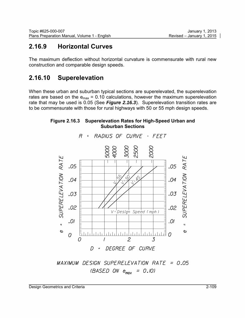
Topic #625-000-007 January 1, 2013 Plans Preparation Manual, Volume 1 - English Revised – January 1, 2015
2.16.9 Horizontal Curves
The maximum deflection without horizontal curvature is commensurate with rural new construction and comparable design speeds.
2.16.10 Superelevation
When these urban and suburban typical sections are superelevated, the superelevation rates are based on the emax = 0.10 calculations, however the maximum superelevation rate that may be used is 0.05 (See Figure 2.16.3). Superelevation transition rates are to be commensurate with those for rural highways with 50 or 55 mph design speeds.
Figure 2.16.3 Superelevation Rates for High-Speed Urban and Suburban Sections
Design Geometrics and Criteria 2-109

Topic #625-000-007 January 1, 2013 Plans Preparation Manual, Volume 1 - English Revised – January 1, 2015
2.16.11 Lateral Offset
Lateral offset requirements are to be commensurate with new construction conditions for flush shoulder highways.
Design Geometrics and Criteria 2-110