Ten Easy Steps to Intersections in AutoCAD Civil 3D · PDF fileTen Easy Steps to Intersections...
20
Ten Easy Steps to Intersections in AutoCAD ® Civil 3D ® Robert Gadbaw – Team Blue22 Ltd. CV110-2L This class takes students step by step through creating an intersection using Civil 3D 2009. Students will learn about alignments, profiles, assemblies and corridors. We'll take all of these components and pull them together to create an intersection. Everyone will start with a surface and polylines that represent the intersection layout. About the Speaker: Robert Gadbaw has been working in the civil engineering industry for over 18 years as a draftsman, designer, technician, trainer, and support engineer. His many years of experience have come not only from the U.S., but also New Zealand, Australia, and other countries. In 2006, Robert started his own consulting firm, Blue22 Ltd., a Civil 3D® consulting and training firm that assists companies worldwide. In 2007, Robert's new company, Team Blue22 Ltd., became an Autodesk Reseller in New Zealand.
Transcript of Ten Easy Steps to Intersections in AutoCAD Civil 3D · PDF fileTen Easy Steps to Intersections...
Ten Easy Steps to Intersections in AutoCAD ®
Civil 3D ®
Robert Gadbaw – Team Blue22 Ltd.
CV110-2L This class takes students step by step through creating an intersection using Civil 3D 2009.
Students will learn about alignments, profiles, assemblies and corridors. We'll take all of these components and pull them together to create an intersection. Everyone will start with a surface and polylines that represent the intersection layout.
About the Speaker: Robert Gadbaw has been working in the civil engineering industry for over 18 years as a draftsman, designer, technician, trainer, and support engineer. His many years of experience have come not only from the U.S., but also New Zealand, Australia, and other countries. In 2006, Robert started his own consulting firm, Blue22 Ltd., a Civil 3D® consulting and training firm that assists companies worldwide. In 2007, Robert's new company, Team Blue22 Ltd., became an Autodesk Reseller in New Zealand.
Ten Easy Steps to Intersections
3
Ten Easy Steps to Intersections
#1: Layout the Intersection
Layout the Intersection has two meanings:
1. Draw the intersection in plan view. 2. Sketch out the intersection on a piece of paper.
Sketching the intersection on paper helps you visualize how the intersection is constructed.
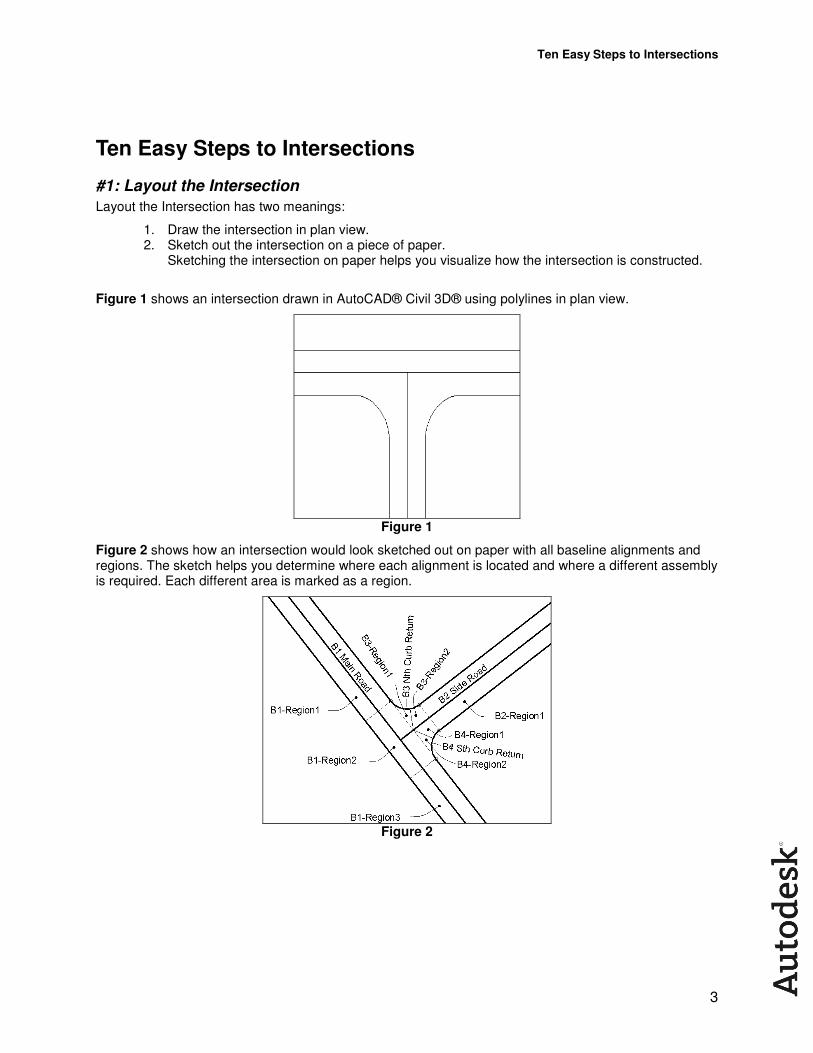
Figure 1 shows an intersection drawn in AutoCAD® Civil 3D® using polylines in plan view.
Figure 1
Figure 2 shows how an intersection would look sketched out on paper with all baseline alignments and regions. The sketch helps you determine where each alignment is located and where a different assembly is required. Each different area is marked as a region.
Figure 2
Ten Easy Steps to Intersections
4
#2: Create Alignments
In Figure 2, four alignments are required. In this exercise, create and name the alignments as follows:
• Main Road
• Side Road
• SW CR
• SE CR
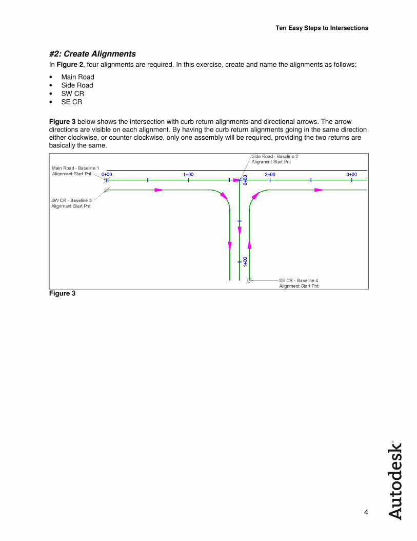
Figure 3 below shows the intersection with curb return alignments and directional arrows. The arrow directions are visible on each alignment. By having the curb return alignments going in the same direction either clockwise, or counter clockwise, only one assembly will be required, providing the two returns are basically the same.
Figure 3
Ten Easy Steps to Intersections
5
Step-by-Step Instructions:
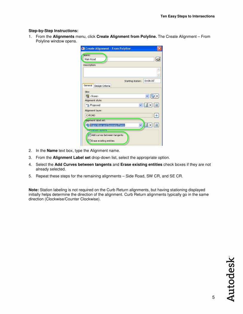
1. From the Alignments menu, click Create Alignment from Polyline. The Create Alignment – From Polyline window opens.
2. In the Name text box, type the Alignment name.
3. From the Alignment Label set drop-down list, select the appropriate option.
4. Select the Add Curves between tangents and Erase existing entities check boxes if they are not already selected.
5. Repeat these steps for the remaining alignments – Side Road, SW CR, and SE CR.
Note: Station labeling is not required on the Curb Return alignments, but having stationing displayed initially helps determine the direction of the alignment. Curb Return alignments typically go in the same direction (Clockwise/Counter Clockwise).
Ten Easy Steps to Intersections
6
#3: Create Assemblies
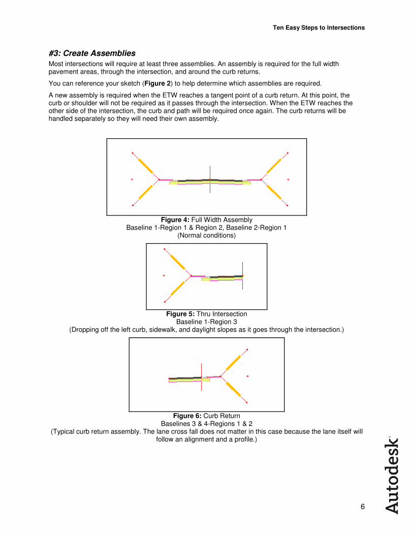
Most intersections will require at least three assemblies. An assembly is required for the full width pavement areas, through the intersection, and around the curb returns.
You can reference your sketch (Figure 2) to help determine which assemblies are required.
A new assembly is required when the ETW reaches a tangent point of a curb return. At this point, the curb or shoulder will not be required as it passes through the intersection. When the ETW reaches the other side of the intersection, the curb and path will be required once again. The curb returns will be handled separately so they will need their own assembly.
Figure 4: Full Width Assembly
Baseline 1-Region 1 & Region 2, Baseline 2-Region 1 (Normal conditions)
Figure 5: Thru Intersection
Baseline 1-Region 3 (Dropping off the left curb, sidewalk, and daylight slopes as it goes through the intersection.)
Figure 6: Curb Return
Baselines 3 & 4-Regions 1 & 2 (Typical curb return assembly. The lane cross fall does not matter in this case because the lane itself will
follow an alignment and a profile.)
Ten Easy Steps to Intersections
7
Step-by-Step Instructions:
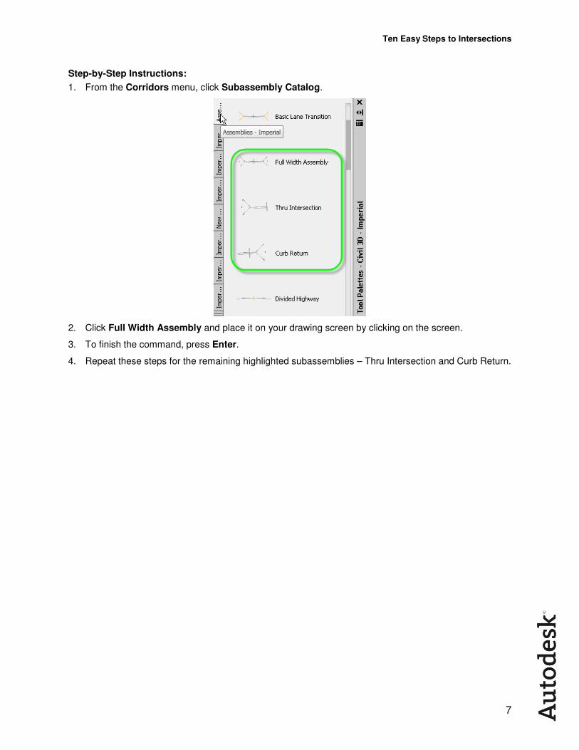
1. From the Corridors menu, click Subassembly Catalog.
2. Click Full Width Assembly and place it on your drawing screen by clicking on the screen.
3. To finish the command, press Enter.
4. Repeat these steps for the remaining highlighted subassemblies – Thru Intersection and Curb Return.
Ten Easy Steps to Intersections
8
#4: Create Profiles for the Main Road Alignment ONLY
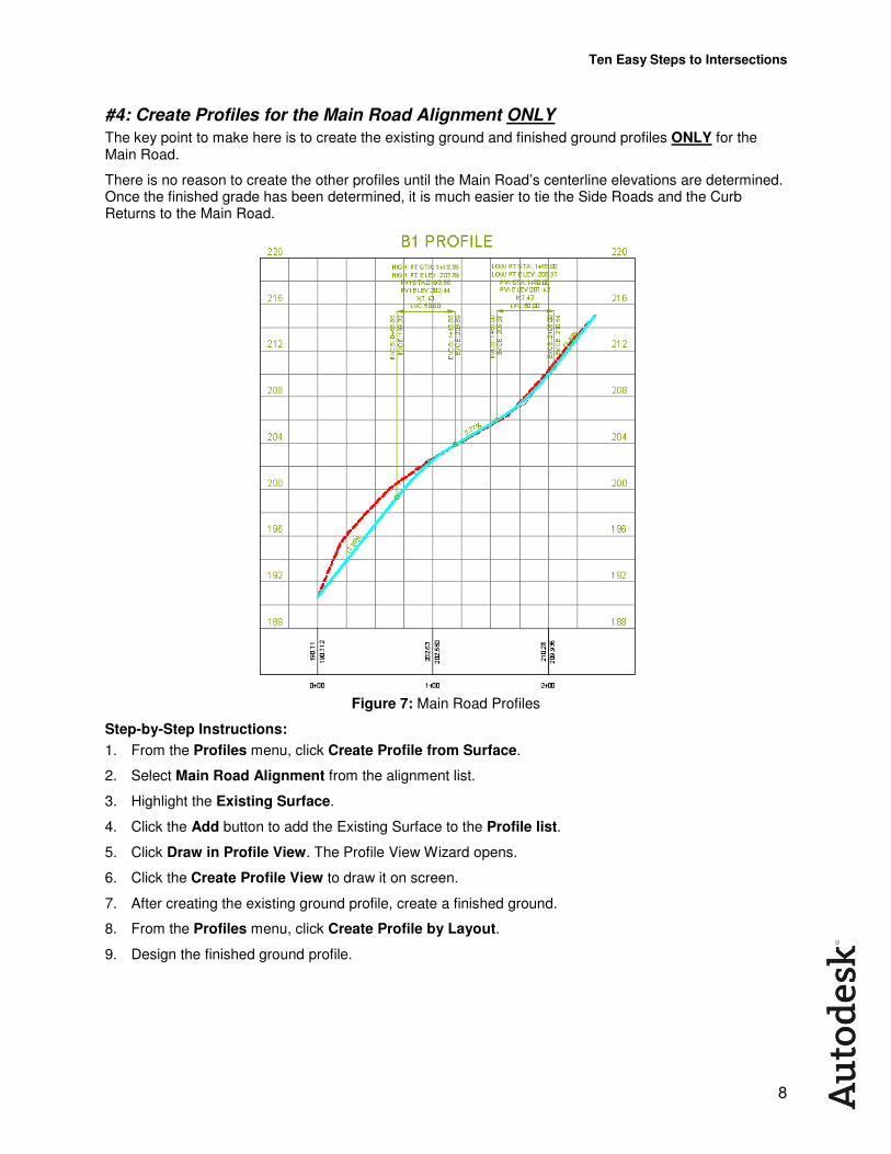
The key point to make here is to create the existing ground and finished ground profiles ONLY for the Main Road.
There is no reason to create the other profiles until the Main Road’s centerline elevations are determined. Once the finished grade has been determined, it is much easier to tie the Side Roads and the Curb Returns to the Main Road.
Figure 7: Main Road Profiles
Step-by-Step Instructions:
1. From the Profiles menu, click Create Profile from Surface.
2. Select Main Road Alignment from the alignment list.
3. Highlight the Existing Surface.
4. Click the Add button to add the Existing Surface to the Profile list.
5. Click Draw in Profile View. The Profile View Wizard opens.
6. Click the Create Profile View to draw it on screen.
7. After creating the existing ground profile, create a finished ground.
8. From the Profiles menu, click Create Profile by Layout.
9. Design the finished ground profile.
Ten Easy Steps to Intersections
9
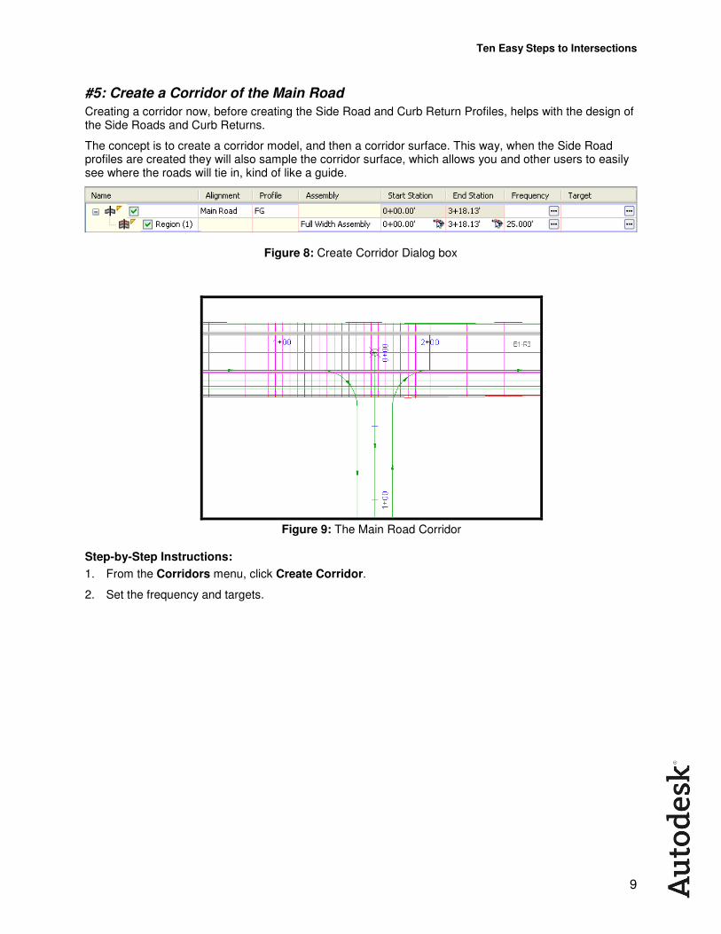
#5: Create a Corridor of the Main Road
Creating a corridor now, before creating the Side Road and Curb Return Profiles, helps with the design of the Side Roads and Curb Returns.
The concept is to create a corridor model, and then a corridor surface. This way, when the Side Road profiles are created they will also sample the corridor surface, which allows you and other users to easily see where the roads will tie in, kind of like a guide.
Figure 8: Create Corridor Dialog box
Figure 9: The Main Road Corridor
Step-by-Step Instructions:
1. From the Corridors menu, click Create Corridor.
2. Set the frequency and targets.
Ten Easy Steps to Intersections
10
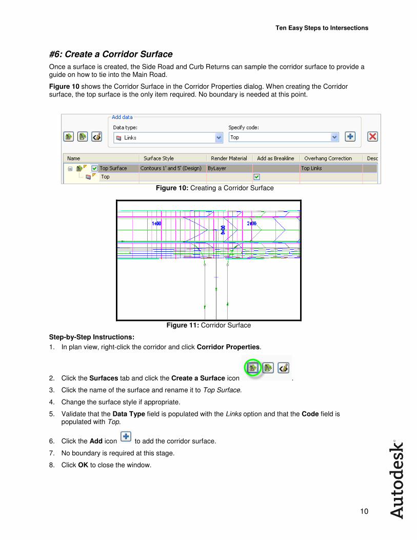
#6: Create a Corridor Surface
Once a surface is created, the Side Road and Curb Returns can sample the corridor surface to provide a guide on how to tie into the Main Road.
Figure 10 shows the Corridor Surface in the Corridor Properties dialog. When creating the Corridor surface, the top surface is the only item required. No boundary is needed at this point.
Figure 10: Creating a Corridor Surface
Figure 11: Corridor Surface
Step-by-Step Instructions:
1. In plan view, right-click the corridor and click Corridor Properties.
2. Click the Surfaces tab and click the Create a Surface icon .
3. Click the name of the surface and rename it to Top Surface.
4. Change the surface style if appropriate.
5. Validate that the Data Type field is populated with the Links option and that the Code field is populated with Top.
6. Click the Add icon to add the corridor surface.
7. No boundary is required at this stage.
8. Click OK to close the window.
Ten Easy Steps to Intersections
11
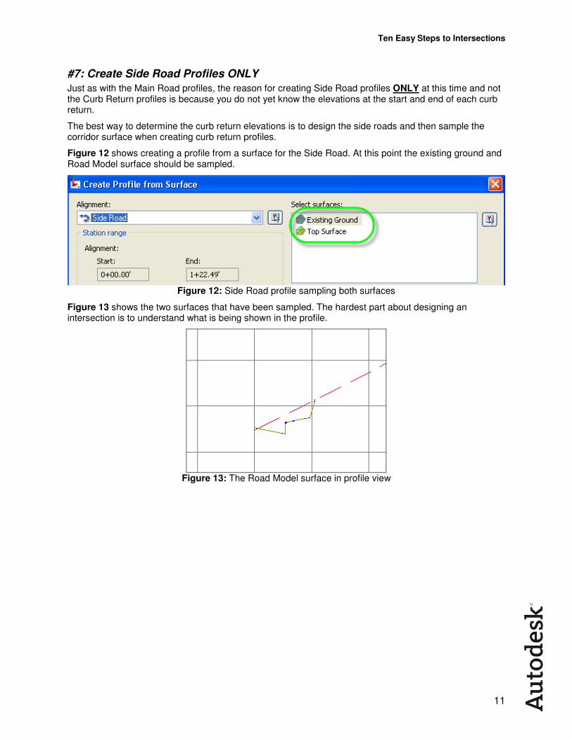
#7: Create Side Road Profiles ONLY
Just as with the Main Road profiles, the reason for creating Side Road profiles ONLY at this time and not the Curb Return profiles is because you do not yet know the elevations at the start and end of each curb return.
The best way to determine the curb return elevations is to design the side roads and then sample the corridor surface when creating curb return profiles.
Figure 12 shows creating a profile from a surface for the Side Road. At this point the existing ground and Road Model surface should be sampled.
Figure 12: Side Road profile sampling both surfaces
Figure 13 shows the two surfaces that have been sampled. The hardest part about designing an intersection is to understand what is being shown in the profile.
Figure 13: The Road Model surface in profile view
Ten Easy Steps to Intersections
12
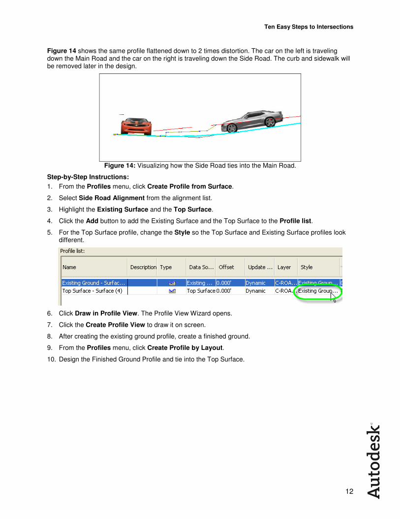
Figure 14 shows the same profile flattened down to 2 times distortion. The car on the left is traveling down the Main Road and the car on the right is traveling down the Side Road. The curb and sidewalk will be removed later in the design.
Figure 14: Visualizing how the Side Road ties into the Main Road.
Step-by-Step Instructions:
1. From the Profiles menu, click Create Profile from Surface.
2. Select Side Road Alignment from the alignment list.
3. Highlight the Existing Surface and the Top Surface.
4. Click the Add button to add the Existing Surface and the Top Surface to the Profile list.
5. For the Top Surface profile, change the Style so the Top Surface and Existing Surface profiles look different.
6. Click Draw in Profile View. The Profile View Wizard opens.
7. Click the Create Profile View to draw it on screen.
8. After creating the existing ground profile, create a finished ground.
9. From the Profiles menu, click Create Profile by Layout.
10. Design the Finished Ground Profile and tie into the Top Surface.
Ten Easy Steps to Intersections
13
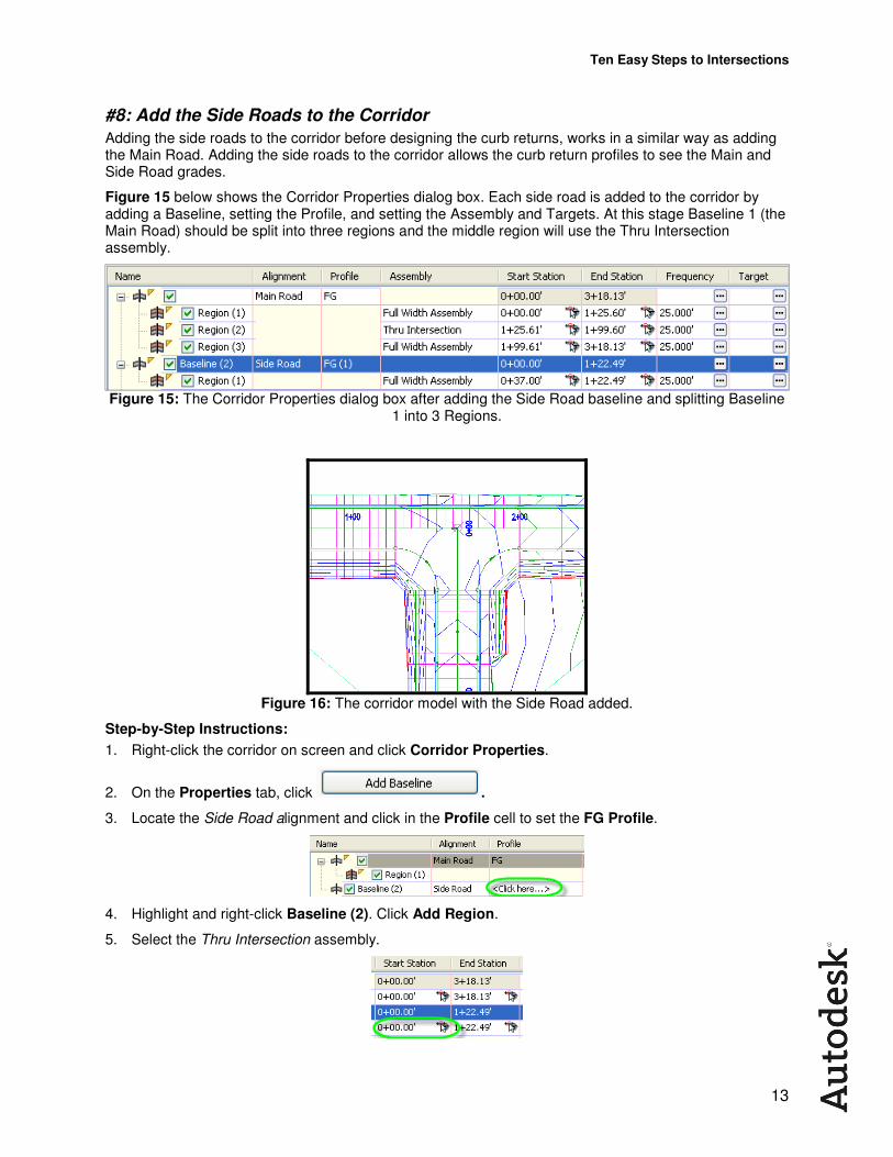
#8: Add the Side Roads to the Corridor
Adding the side roads to the corridor before designing the curb returns, works in a similar way as adding the Main Road. Adding the side roads to the corridor allows the curb return profiles to see the Main and Side Road grades.
Figure 15 below shows the Corridor Properties dialog box. Each side road is added to the corridor by adding a Baseline, setting the Profile, and setting the Assembly and Targets. At this stage Baseline 1 (the Main Road) should be split into three regions and the middle region will use the Thru Intersection assembly.
Figure 15: The Corridor Properties dialog box after adding the Side Road baseline and splitting Baseline 1 into 3 Regions.
Figure 16: The corridor model with the Side Road added.
Step-by-Step Instructions:
1. Right-click the corridor on screen and click Corridor Properties.
2. On the Properties tab, click .
3. Locate the Side Road alignment and click in the Profile cell to set the FG Profile.
4. Highlight and right-click Baseline (2). Click Add Region.
5. Select the Thru Intersection assembly.
Ten Easy Steps to Intersections
14
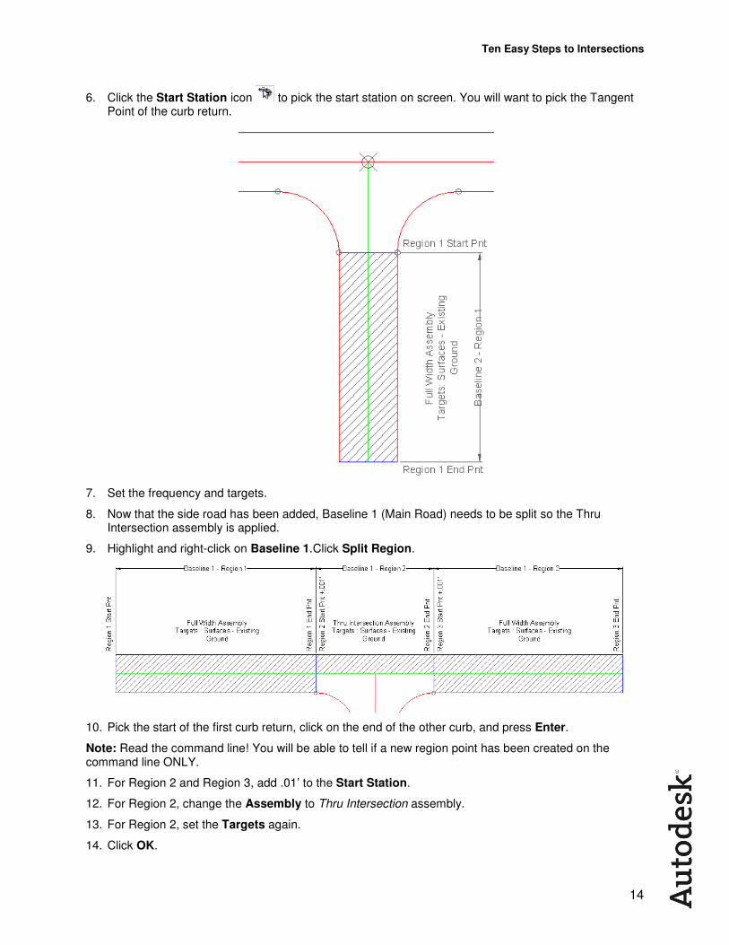
6. Click the Start Station icon to pick the start station on screen. You will want to pick the Tangent Point of the curb return.
7. Set the frequency and targets.
8. Now that the side road has been added, Baseline 1 (Main Road) needs to be split so the Thru Intersection assembly is applied.
9. Highlight and right-click on Baseline 1.Click Split Region.
10. Pick the start of the first curb return, click on the end of the other curb, and press Enter.
Note: Read the command line! You will be able to tell if a new region point has been created on the command line ONLY.
11. For Region 2 and Region 3, add .01’ to the Start Station.
12. For Region 2, change the Assembly to Thru Intersection assembly.
13. For Region 2, set the Targets again.
14. Click OK.
Ten Easy Steps to Intersections
15
#9: Create the Curb Return Profiles
This step is the most critical and most confusing. At this stage everything is completed except the curb returns.
When creating the curb return profile from a surface all that is required is the Road Model surface. The existing ground is not required because the curb returns are constrained at both ends by the Main Road and Side Roads. Showing the existing ground surface only confuses the issue.
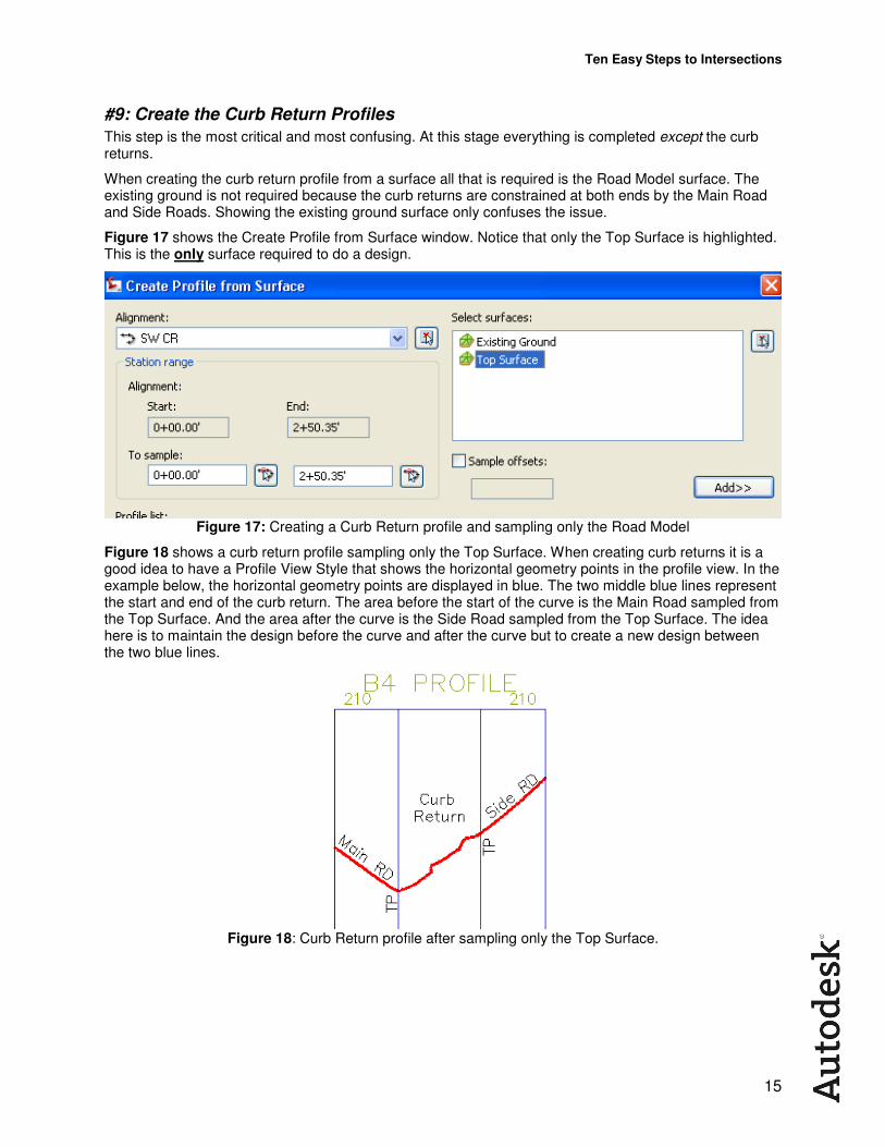
Figure 17 shows the Create Profile from Surface window. Notice that only the Top Surface is highlighted. This is the only surface required to do a design.
Figure 17: Creating a Curb Return profile and sampling only the Road Model
Figure 18 shows a curb return profile sampling only the Top Surface. When creating curb returns it is a good idea to have a Profile View Style that shows the horizontal geometry points in the profile view. In the example below, the horizontal geometry points are displayed in blue. The two middle blue lines represent the start and end of the curb return. The area before the start of the curve is the Main Road sampled from the Top Surface. And the area after the curve is the Side Road sampled from the Top Surface. The idea here is to maintain the design before the curve and after the curve but to create a new design between the two blue lines.
Figure 18: Curb Return profile after sampling only the Top Surface.
Ten Easy Steps to Intersections
16
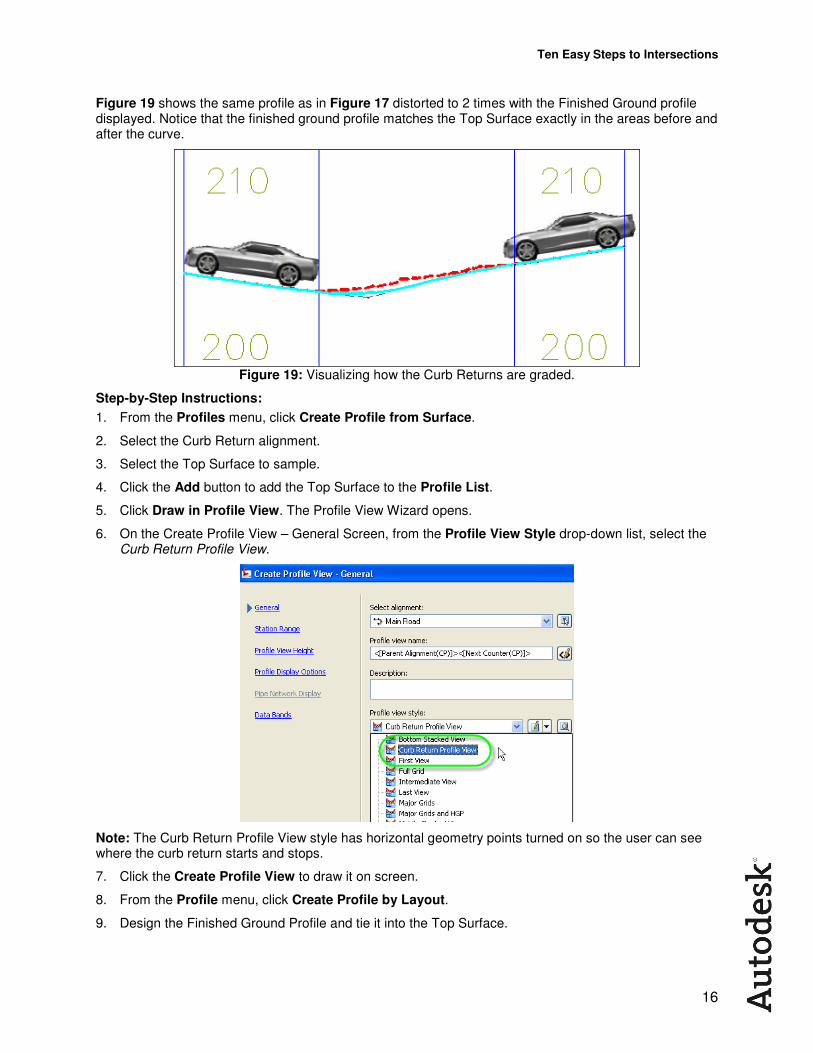
Figure 19 shows the same profile as in Figure 17 distorted to 2 times with the Finished Ground profile displayed. Notice that the finished ground profile matches the Top Surface exactly in the areas before and after the curve.
Figure 19: Visualizing how the Curb Returns are graded.
Step-by-Step Instructions:
1. From the Profiles menu, click Create Profile from Surface.
2. Select the Curb Return alignment.
3. Select the Top Surface to sample.
4. Click the Add button to add the Top Surface to the Profile List.
5. Click Draw in Profile View. The Profile View Wizard opens.
6. On the Create Profile View – General Screen, from the Profile View Style drop-down list, select the Curb Return Profile View.
Note: The Curb Return Profile View style has horizontal geometry points turned on so the user can see where the curb return starts and stops.
7. Click the Create Profile View to draw it on screen.
8. From the Profile menu, click Create Profile by Layout.
9. Design the Finished Ground Profile and tie it into the Top Surface.
Ten Easy Steps to Intersections
17
#10: Add the Curb Returns to the Corridor
The final step is the most challenging. Creating the sketch at the start really pays off in this step. Visualizing what goes where is the key to finishing off the intersection.
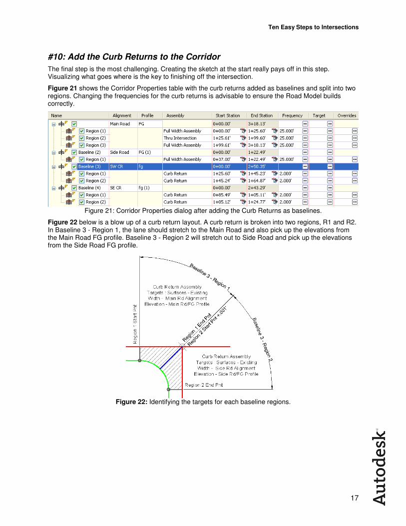
Figure 21 shows the Corridor Properties table with the curb returns added as baselines and split into two regions. Changing the frequencies for the curb returns is advisable to ensure the Road Model builds correctly.
Figure 21: Corridor Properties dialog after adding the Curb Returns as baselines.
Figure 22 below is a blow up of a curb return layout. A curb return is broken into two regions, R1 and R2. In Baseline 3 - Region 1, the lane should stretch to the Main Road and also pick up the elevations from the Main Road FG profile. Baseline 3 - Region 2 will stretch out to Side Road and pick up the elevations from the Side Road FG profile.
Figure 22: Identifying the targets for each baseline regions.
Ten Easy Steps to Intersections
18
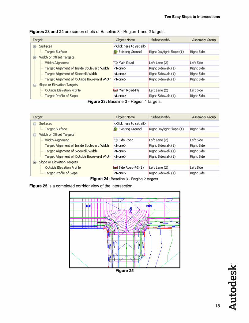
Figures 23 and 24 are screen shots of Baseline 3 - Region 1 and 2 targets.
Figure 23: Baseline 3 - Region 1 targets.
Figure 24: Baseline 3 - Region 2 targets.
Figure 25 is a completed corridor view of the intersection.
Figure 25
Ten Easy Steps to Intersections
19
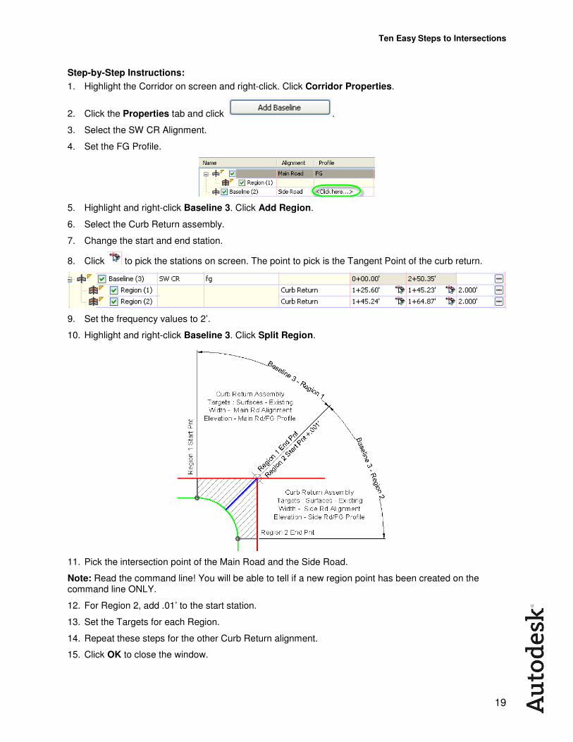
Step-by-Step Instructions:
1. Highlight the Corridor on screen and right-click. Click Corridor Properties.
2. Click the Properties tab and click .
3. Select the SW CR Alignment.
4. Set the FG Profile.
5. Highlight and right-click Baseline 3. Click Add Region.
6. Select the Curb Return assembly.
7. Change the start and end station.
8. Click to pick the stations on screen. The point to pick is the Tangent Point of the curb return.
9. Set the frequency values to 2’.
10. Highlight and right-click Baseline 3. Click Split Region.
11. Pick the intersection point of the Main Road and the Side Road.
Note: Read the command line! You will be able to tell if a new region point has been created on the command line ONLY.
12. For Region 2, add .01’ to the start station.
13. Set the Targets for each Region.
14. Repeat these steps for the other Curb Return alignment.
15. Click OK to close the window.
Ten Easy Steps to Intersections
20
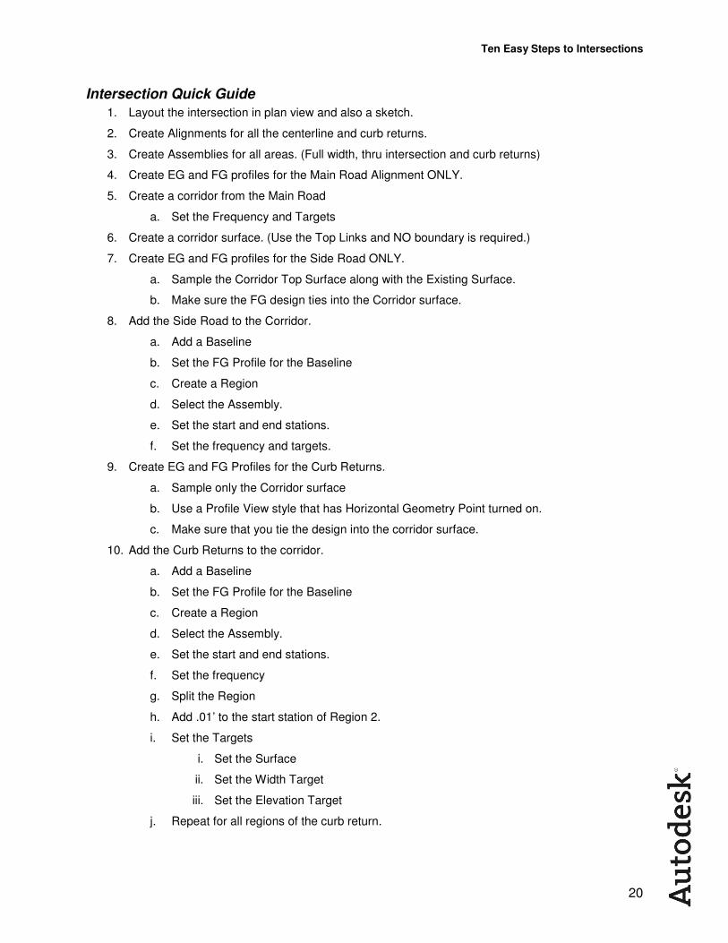
Intersection Quick Guide
1. Layout the intersection in plan view and also a sketch.
2. Create Alignments for all the centerline and curb returns.
3. Create Assemblies for all areas. (Full width, thru intersection and curb returns)
4. Create EG and FG profiles for the Main Road Alignment ONLY.
5. Create a corridor from the Main Road
a. Set the Frequency and Targets
6. Create a corridor surface. (Use the Top Links and NO boundary is required.)
7. Create EG and FG profiles for the Side Road ONLY.
a. Sample the Corridor Top Surface along with the Existing Surface.
b. Make sure the FG design ties into the Corridor surface.
8. Add the Side Road to the Corridor.
a. Add a Baseline
b. Set the FG Profile for the Baseline
c. Create a Region
d. Select the Assembly.
e. Set the start and end stations.
f. Set the frequency and targets.
9. Create EG and FG Profiles for the Curb Returns.
a. Sample only the Corridor surface
b. Use a Profile View style that has Horizontal Geometry Point turned on.
c. Make sure that you tie the design into the corridor surface.
10. Add the Curb Returns to the corridor.
a. Add a Baseline
b. Set the FG Profile for the Baseline
c. Create a Region
d. Select the Assembly.
e. Set the start and end stations.
f. Set the frequency
g. Split the Region
h. Add .01’ to the start station of Region 2.
i. Set the Targets
i. Set the Surface
ii. Set the Width Target
iii. Set the Elevation Target
j. Repeat for all regions of the curb return.