Temperature control - Q Plus, perslucht in beweging · RPL 08.1152/DR/KR 12 +90° nitrile-Blue ring...
12
NCI 33 Temperature control The Stäubli distribution manifold
Transcript of Temperature control - Q Plus, perslucht in beweging · RPL 08.1152/DR/KR 12 +90° nitrile-Blue ring...
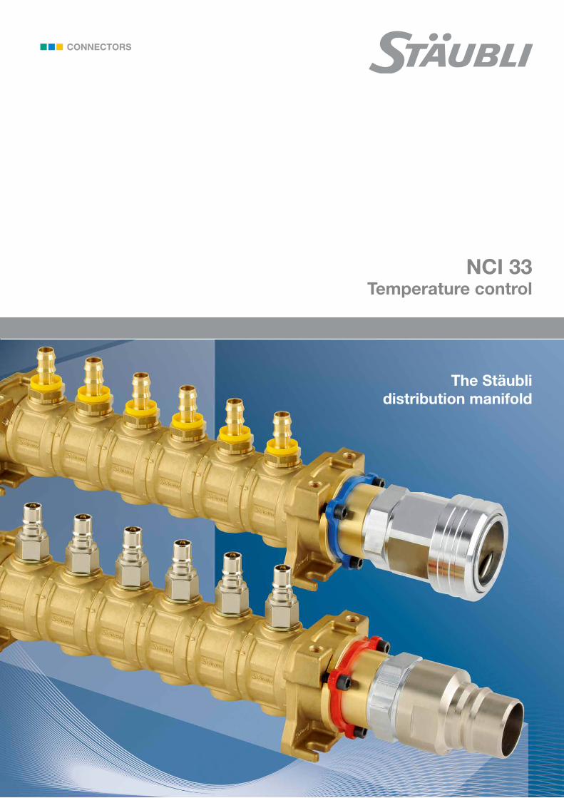
NCI 33Temperature control
The Stäublidistribution manifold
2
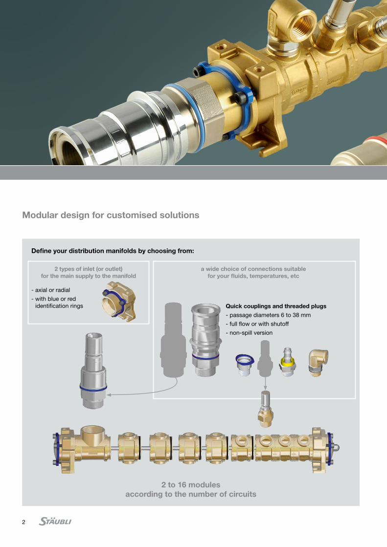
Modular design for customised solutions
2 to 16 modules according to the number of circuits
Define your distribution manifolds by choosing from:
2 types of inlet (or outlet) for the main supply to the manifold
- axial or radial
- with blue or red identification rings
a wide choice of connections suitable for your fluids, temperatures, etc
Quick couplings and threaded plugs
- passage diameters 6 to 38 mm
- full flow or with shutoff
- non-spill version
3
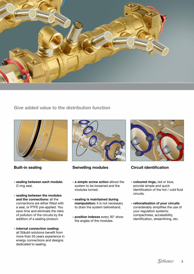
Give added value to the distribution function
Built-in sealing
- sealing between each module: O ring seal.
- sealing between the modules and the connections: all the connections are either fitted with a seal, or PTFE pre-applied. You save time and eliminate the risks of pollution of the circuits by the addition of a sealing product.
- internal connection sealing: all Stäubli solutions benefit from more than 50 years experience in energy connections and designs dedicated to sealing.
Swivelling modules
- a simple screw action allows the system to be loosened and the modules turned.
- sealing is maintained during manipulation: it is not necessary to drain the system beforehand.
- position indexes every 30° show the angles of the modules.
Circuit identification
- coloured rings, red or blue, provide simple and quick identification of the hot / cold fluid circuits.
- rationalisation of your circuits considerably simplifies the use of your regulation systems: compactness, accessibility, identification, streamlining, etc.
4
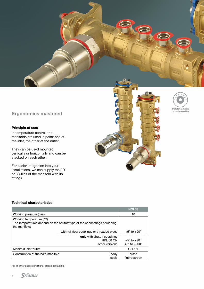
Technical characteristics
Principle of use:In temperature control, the manifolds are used in pairs: one at the inlet, the other at the outlet.
They can be used mounted vertically or horizontally and can be stacked on each other.
For easier integration into your installations, we can supply the 2D or 3D files of the manifold with its fittings.
For all other usage conditions: please contact us
Ergonomics mastered
NCI 33
Working pressure (bars) 10
Working temperature (°C) The temperatures depend on the shutoff type of the connectings equipping the manifold:
with full flow couplings or threaded plugs +5° to +90°
only with shutoff couplings RPL 08 ON
other versions
+5° to +90°
+5° to +200°
Manifold inlet/outlet G 1 1/4
Construction of the bare manifold body seals
brassfluorocarbon
For all other usage conditions: please contact us.
PA
TE N T
ED
US Patent 8.356.632 and other countries
5
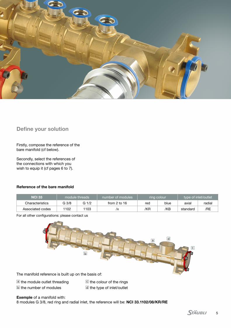
Firstly, compose the reference of the bare manifold (cf below).
Secondly, select the references of the connections with which you wish to equip it (cf pages 6 to 7).
a the module outlet threadingb the number of modules
c the colour of the ringsd the type of inlet/outlet
The manifold reference is built up on the basis of:
Exemple of a manifold with: 8 modules G 3/8, red ring and radial inlet, the reference will be: NCI 33.1102/08/KR/RE
NCI 33 module threads number of modules ring colour type of inlet/outlet
Characteristics G 3/8 G 1/2 from 2 to 16 red blue axial radial
Associated codes 1102 1103 /x /KR /KB standard /RE
Reference of the bare manifold
a
b
c
d
Define your solution
For all other configurations: please contact us
6
74
6
G 1
1/4
E
G 3/8 orG 1/2
70
74
6
82
E
G 1 1/4G 3/8 orG 1/2
70
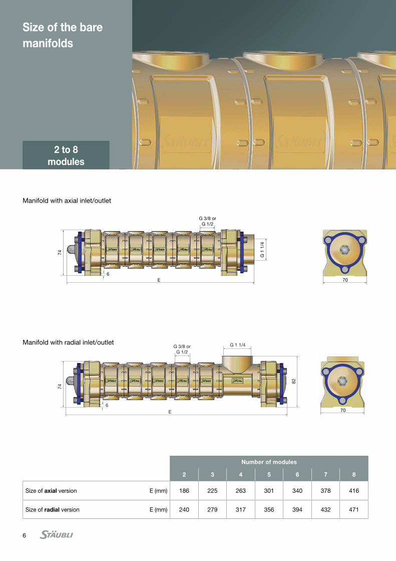
Manifold with axial inlet/outlet
Manifold with radial inlet/outlet
Size of the bare manifolds
2 to 8 modules
Number of modules
2 3 4 5 6 7 8
Size of axial version E (mm) 186 225 263 301 340 378 416
Size of radial version E (mm) 240 279 317 356 394 432 471
7
74
6
E
G 3/8 orG 1/2
G 1
1/4
74
6
82
E
G 1 1/4G 3/8 or
G 1/2
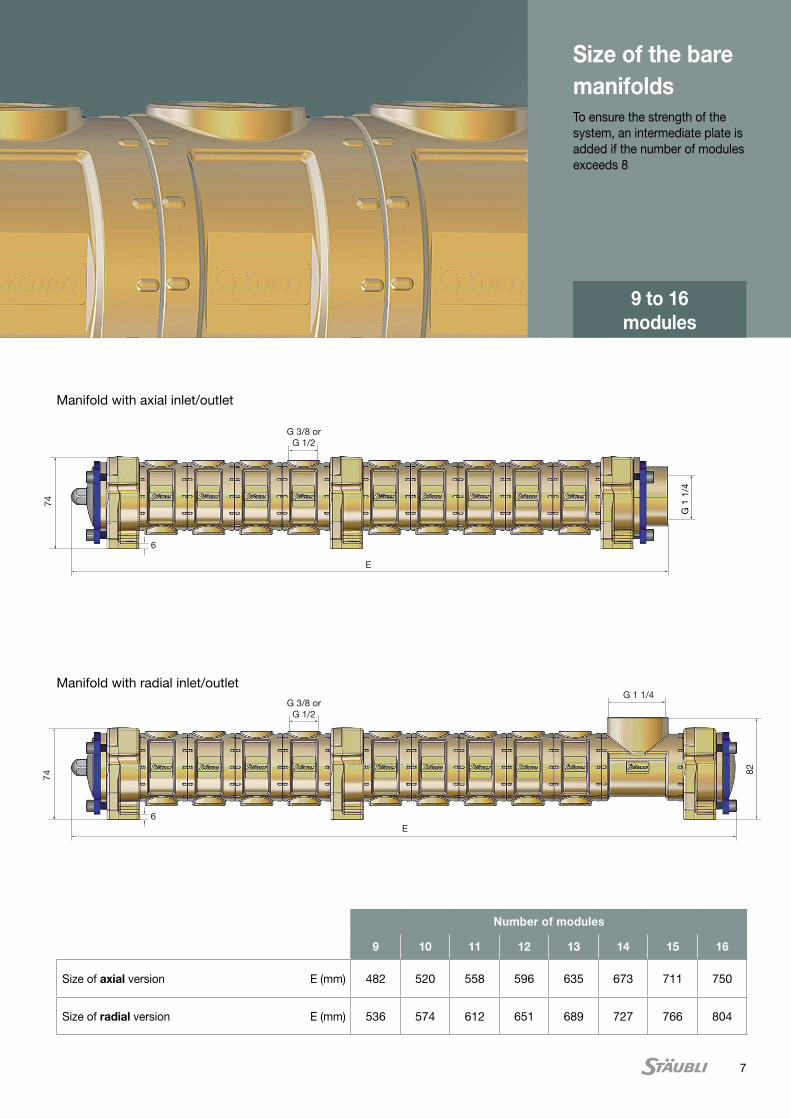
Manifold with axial inlet/outlet
Manifold with radial inlet/outlet
9 to 16 modules
Size of the bare manifoldsTo ensure the strength of the system, an intermediate plate is added if the number of modules exceeds 8
Number of modules
9 10 11 12 13 14 15 16
Size of axial version E (mm) 482 520 558 596 635 673 711 750
Size of radial version E (mm) 536 574 612 651 689 727 766 804
8
hose inside diameter (mm)
max. working temperature* (°C)
seal Part numbers
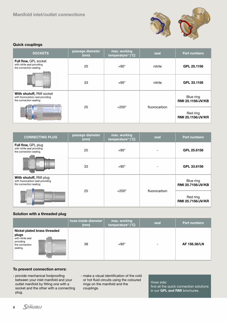
Nickel plated brass threaded plugswith nitrile sealproviding the connectionsealing.
38 +90° - AF 156.38/LN
Manifold inlet/outlet connections
Quick couplings
Solution with a threaded plug
To prevent connection errors:
- provide mechanical foolproofing between your inlet manifold and your outlet manifold by fitting one with a socket and the other with a connecting plug.
- make a visual identification of the cold or hot fluid circuits using the coloured rings on the manifold and the couplings.
Hose side:find all the quick connection solutions in our GPL and RMI brochures.
SOCKETSpassage diameter
(mm)max. working
temperature* (°C)seal Part numbers
Full flow, GPL socket with nitrile seal providing the connection sealing. 25 +90° nitrile GPL 25.1156
33 +90° nitrile GPL 33.1156
With shutoff, RMI socketwith fluorocarbon seal providing the connection sealing.
25 +200° fluorocarbon
Blue ringRMI 25.1156/JV/KB
Red ringRMI 25.1156/JV/KR
CONNECTING PLUGpassage diameter
(mm)max. working
temperature* (°C)seal Part numbers
Full flow, GPL plugwith nitrile seal providing the connection sealing. 25 +90° - GPL 25.6156
33 +90° - GPL 33.6156
With shutoff, RMI plugwith fluorocarbon seal providing the connection sealing.
25 +200° fluorocarbon
Blue ringRMI 25.7156/JV/KB
Red ringRMI 25.7156/JV/KR
9
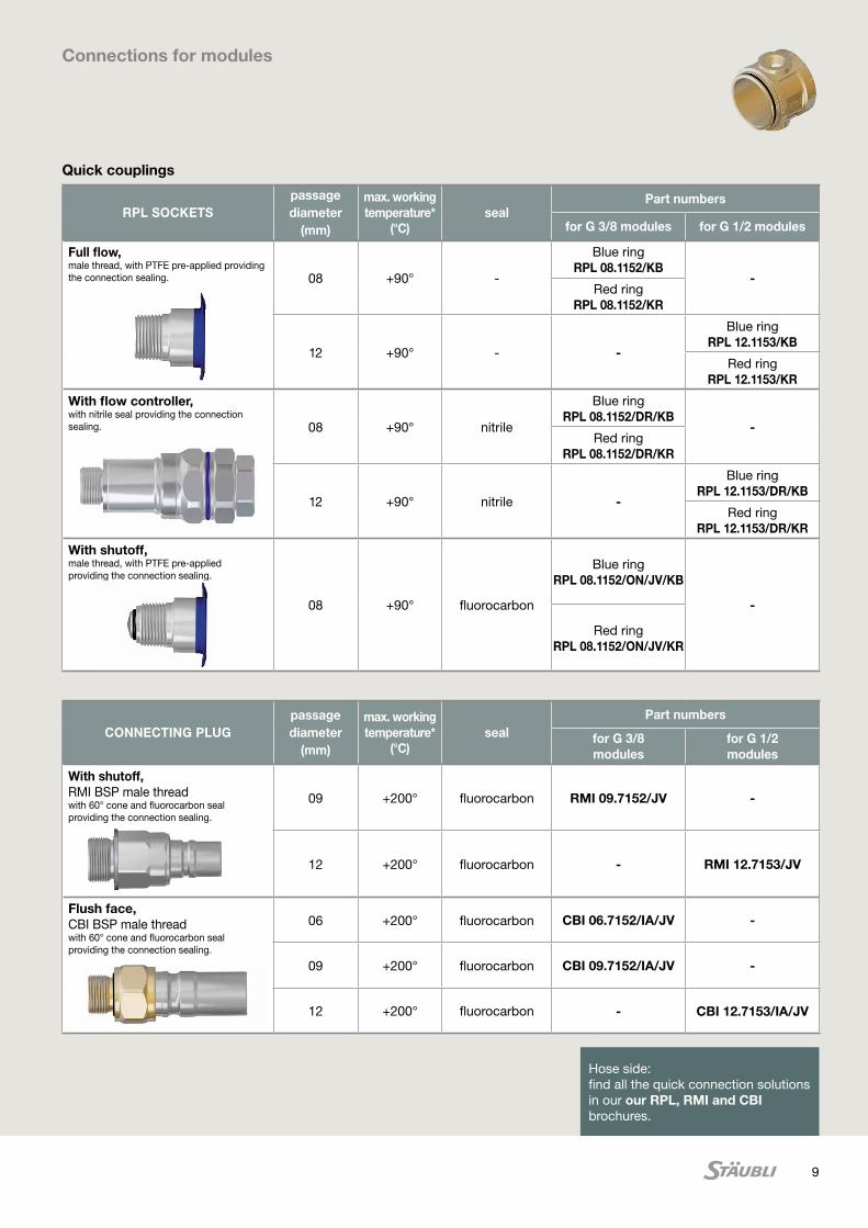
Connections for modules
Hose side:find all the quick connection solutions in our our RPL, RMI and CBI brochures.
CONNECTING PLUGpassage diameter
(mm)
max. working temperature*
(°C)seal
Part numbers
for G 3/8 modules
for G 1/2 modules
With shutoff,RMI BSP male thread with 60° cone and fluorocarbon seal providing the connection sealing.
09 +200° fluorocarbon RMI 09.7152/JV -
12 +200° fluorocarbon - RMI 12.7153/JV
Flush face,CBI BSP male thread with 60° cone and fluorocarbon seal providing the connection sealing.
06 +200° fluorocarbon CBI 06.7152/IA/JV -
09 +200° fluorocarbon CBI 09.7152/IA/JV -
12 +200° fluorocarbon - CBI 12.7153/IA/JV
Quick couplings
RPL SOCKETSpassage diameter
(mm)
max. working temperature*
(°C)seal
Part numbers
for G 3/8 modules for G 1/2 modules
Full flow,male thread, with PTFE pre-applied providing the connection sealing. 08 +90° -
Blue ringRPL 08.1152/KB
-Red ring
RPL 08.1152/KR
12 +90° - -
Blue ringRPL 12.1153/KB
Red ringRPL 12.1153/KR
With flow controller,with nitrile seal providing the connection sealing. 08 +90° nitrile
Blue ringRPL 08.1152/DR/KB
-Red ring
RPL 08.1152/DR/KR
12 +90° nitrile -
Blue ringRPL 12.1153/DR/KB
Red ringRPL 12.1153/DR/KR
With shutoff,male thread, with PTFE pre-applied providing the connection sealing.
08 +90° fluorocarbon
Blue ringRPL 08.1152/ON/JV/KB
-
Red ringRPL 08.1152/ON/JV/KR
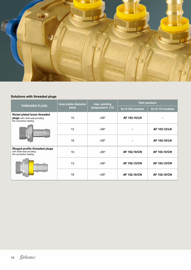
10
Solutions with threaded plugs
THREADED PLUGShose inside diameter
(mm)max. working
temperature* (°C)
Part numbers
for G 3/8 modules for G 1/2 modules
Nickel plated brass threaded plugs with nitrile seal providing the connection sealing.
10 +90° AF 152.10/LN -
12 +90° - AF 153.12/LN
16 +90° - AF 153.16/LN
Ringed profile threaded plugs with nitrile seal providing the connection sealing.
10 +90° AF 152.10/CN AF 153.10/CN
13 +90° AF 152.13/CN AF 153.13/CN
16 +90° AF 152.16/CN AF 153.16/CN
11We reserve the right to modify product specifications without prior notice.
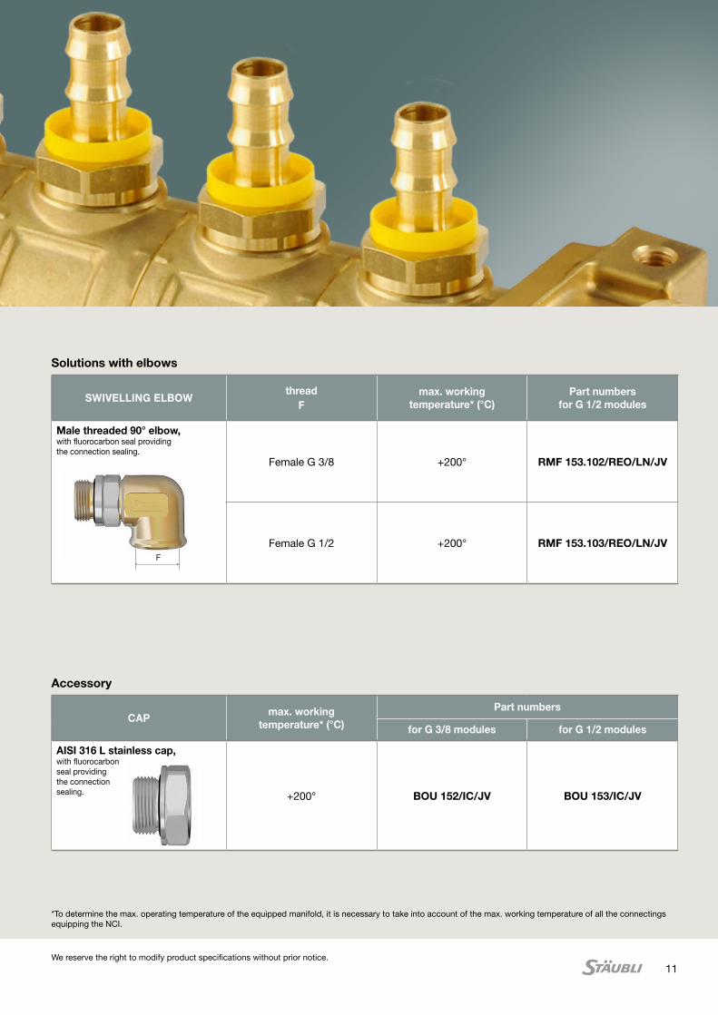
Solutions with elbows
Accessory
SWIVELLING ELBOWthread
Fmax. working
temperature* (°C)Part numbers
for G 1/2 modules
Male threaded 90° elbow, with fluorocarbon seal providing the connection sealing.
Female G 3/8 +200° RMF 153.102/REO/LN/JV
Female G 1/2 +200° RMF 153.103/REO/LN/JVF
CAPmax. working
temperature* (°C)
Part numbers
for G 3/8 modules for G 1/2 modules
AISI 316 L stainless cap, with fluorocarbonseal providingthe connectionsealing. +200° BOU 152/IC/JV BOU 153/IC/JV
*To determine the max. operating temperature of the equipped manifold, it is necessary to take into account of the max. working temperature of all the connectings equipping the NCI.
RD
5010
301C
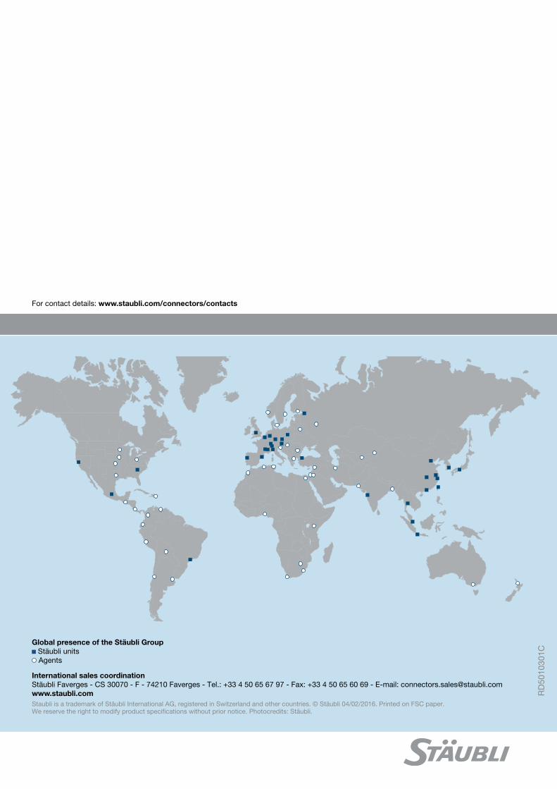
Global presence of the Stäubli Group Stäubli units Agents
www.staubli.comStaubli is a trademark of Stäubli International AG, registered in Switzerland and other countries. © Stäubli 04/02/2016. Printed on FSC paper. We reserve the right to modify product specifications without prior notice. Photocredits: Stäubli.
For contact details: www.staubli.com/connectors/contacts
International sales coordinationStäubli Faverges - CS 30070 - F - 74210 Faverges - Tel.: +33 4 50 65 67 97 - Fax: +33 4 50 65 60 69 - E-mail: [email protected]