
Telex - PDF.TEXTFILES.COMpdf.textfiles.com/manuals/STARINMANUALS/Telex Intercom/Manuals... ·...
40
Telex Operating Instructions RADIOCOM BTR-500/600C TR-500/600C Professional Wireless Intercom Set
Transcript of Telex - PDF.TEXTFILES.COMpdf.textfiles.com/manuals/STARINMANUALS/Telex Intercom/Manuals... ·...

TelexOperating Instructions
RADIOCOM
BTR-500/600CTR-500/600CProfessional WirelessIntercom Set

Table of Contents
Introduction ..........................................................................................................................................1General Description .........................................................................................................................1System Features ...............................................................................................................................1
Base Station Transceiver .....................................................................................................................2Controls And Connections ...............................................................................................................2
Front Panel .................................................................................................................................2Rear Panel ..................................................................................................................................3
Specifications ...................................................................................................................................4Beltpack Transceiver ...........................................................................................................................5
Controls and Connections ................................................................................................................5Specifications ...................................................................................................................................6
Initial Equipment Set-Up ....................................................................................................................7Unpacking ........................................................................................................................................7Antenna Information ........................................................................................................................7
Antenna Connections .................................................................................................................7Antenna Polarization..................................................................................................................8Distance Between Antennas.......................................................................................................8Antenna Placement ....................................................................................................................8Improving Reception/Increasing Range...................................................................................10
Base Station Set-up .......................................................................................................................11Location ...................................................................................................................................11Rack Mounting.........................................................................................................................11Local Headset Connection .......................................................................................................11RF Transmit/Receive Channel Switches..................................................................................11RF Transmit Mode Switch .......................................................................................................12Intercom Type Switch ..............................................................................................................12Dual Listen Switches ...............................................................................................................12Audio Channel Switch .............................................................................................................13Telex In/Out Switch .................................................................................................................13Auxiliary Switch ......................................................................................................................13Auxiliary to I/C Switch (program audio) .................................................................................13Code Switch (BTR-600C Only)...............................................................................................13Interconnection to a Hard-wired Intercom...............................................................................14Auxiliary Audio Connection....................................................................................................17Power Connection ....................................................................................................................17Dummy Load ...........................................................................................................................17
Beltpack Set-up ..............................................................................................................................18Headset Connection .................................................................................................................18RF Transmit/Receive Channel Switches.................................................................................18RF Transmit Mode Switch .......................................................................................................18Code Switch (TR-600C Only) .................................................................................................18Battery Installation...................................................................................................................19
Pre-Walk-Thru Checklist ..................................................................................................................20
-i-
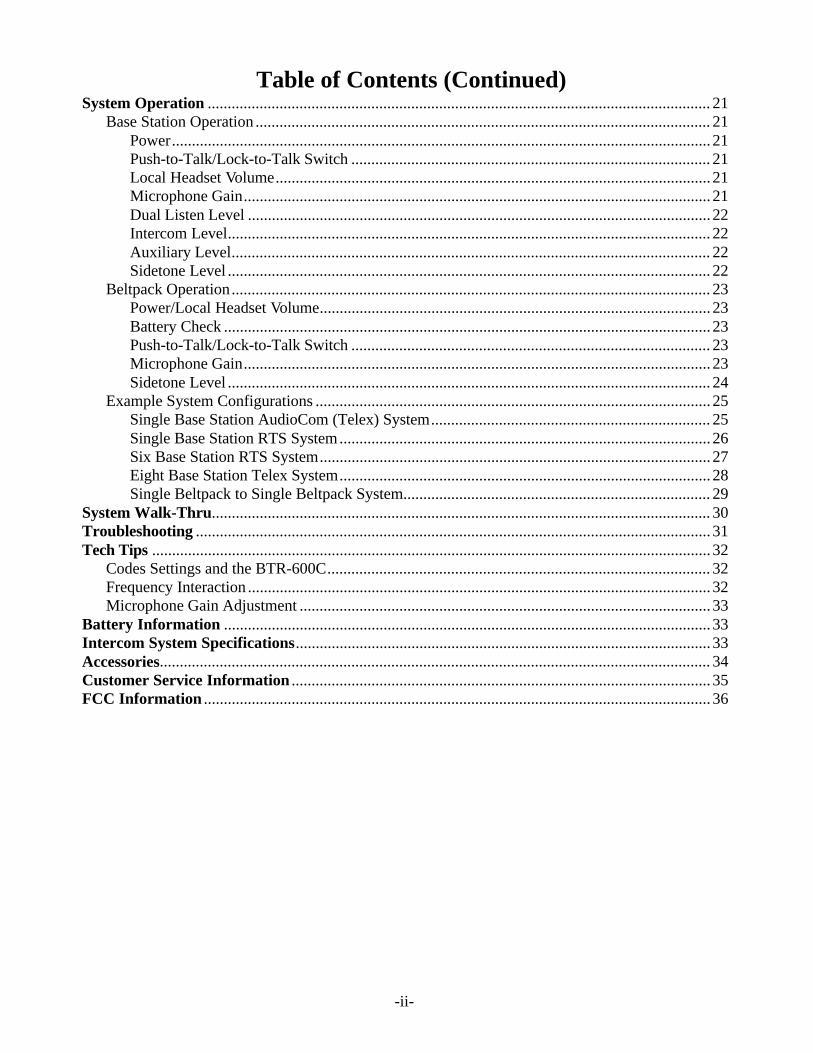
Table of Contents (Continued)System Operation .............................................................................................................................. 21
Base Station Operation .................................................................................................................. 21Power....................................................................................................................................... 21Push-to-Talk/Lock-to-Talk Switch .......................................................................................... 21Local Headset Volume............................................................................................................. 21Microphone Gain..................................................................................................................... 21Dual Listen Level .................................................................................................................... 22Intercom Level......................................................................................................................... 22Auxiliary Level........................................................................................................................ 22Sidetone Level ......................................................................................................................... 22
Beltpack Operation........................................................................................................................ 23Power/Local Headset Volume.................................................................................................. 23Battery Check .......................................................................................................................... 23Push-to-Talk/Lock-to-Talk Switch .......................................................................................... 23Microphone Gain..................................................................................................................... 23Sidetone Level ......................................................................................................................... 24
Example System Configurations ................................................................................................... 25Single Base Station AudioCom (Telex) System...................................................................... 25Single Base Station RTS System............................................................................................. 26Six Base Station RTS System.................................................................................................. 27Eight Base Station Telex System............................................................................................. 28Single Beltpack to Single Beltpack System............................................................................. 29
System Walk-Thru............................................................................................................................. 30Troubleshooting ................................................................................................................................. 31Tech Tips ............................................................................................................................................ 32
Codes Settings and the BTR-600C................................................................................................ 32Frequency Interaction .................................................................................................................... 32Microphone Gain Adjustment ....................................................................................................... 33
Battery Information .......................................................................................................................... 33Intercom System Specifications........................................................................................................ 33Accessories.......................................................................................................................................... 34Customer Service Information ......................................................................................................... 35FCC Information ............................................................................................................................... 36
-ii-

Introduction
General Description
The Telex Radiocom BTR-500 and BTR-600C UHFWireless intercom systems offer the ultimate in reli-able, high performance, high fidelity full duplexcommunications.
The BTR-500 series includes the BTR-500 fre-quency agile base station, working with the TR-500transceiver beltpack. The BTR-500 base station pro-vides full duplex communications with a single belt-pack. Sixteen BTR-500s, or more, may be operatedsimultaneously. Also a single BTR-500 base stationcan accommodate an unlimited number of beltpacksoperating in “Push-to-Transmit” mode.
The BTR-600C series has all the features of theBTR-500 with the addition of digital modulationand encryption for secure communications. Basestation and beltpacks can choose from over 65,000user selectable security codes out of over 16 millionpossible codes by means of four cipher codeswitches on the units. Sixteen BTR-600C, or more,may be operated simultaneously, permitting 16, ormore, discrete full duplex radio channels.
The BTR systems incorporate auto-switching 2channel operation, permitting the beltpack operatorto choose between 2 separate audio channels ofcommunications, with the base station tracking thebeltpack selection. Auto-switching allows the userthe flexibility to create a party-line and a private linewithin the same beltpack.
The BTR-500 and BTR-600C systems are perfectlysuited for stand-alone operation and also can inter-face with Audiocom® (Telex), RTS® TW, as wellas RTS Matrix systems and other 4 wire communi-cations systems. Clear-Com® intercom system mayalso be interfaced to a BTR-500 and BTR-600C sys-tems through the use of a Telex to Clear-Com Inter-face box, see “Accesories” for more information. Inaddition to the external intercom systems interfaceslisted above, the base stations provide connectionsfor auxiliary balanced audio input and output.
The Radiocom BTR series has been designed forreliable, efficient operation. Operating in the 520 to760 MHz range, the units operate reliable at dis-tances of 1,000 feet. With available antenna systemsfrom Telex, the effective operating range can be ex-tended. The high efficiency beltpacks provide 12hours of uninterrupted operation using standard al-kaline batteries.
System Features
Compatible with Audiocom (Telex), RTS TW, RTSMatrix, Clear-Com (with external interface box),and other wired intercom types.
Intercom loop thru jacks for connecting multipleunits.
Full Duplex (simultaneous talk and listen) operation.
Beltpack TR unit contained in a weather and shockresistant die cast magnesium case.
Digitally encrypted RF (Radio Frequency) link forsecure communication on the 600C version.
Flexible power requirements. The base unit can bepowered by any 12 to 15 Volt, AC or DC, 400 mApower source. An external AC wall supply is sup-plied with the unit.
Two transmit and two receive RF channels to helpavoid radio interference.
Base stations are table or rack mountable.
Audio channel switch on the beltpack unit enables itto remotely control the intercom channel on the baseunit.
Two channels of audio.
Beltpack batteries last up to 12 hours when usingstandard AA alkaline batteries.
Audio out jack for P.A. systems or other externalaudio systems.
RTS® and Audiocom® are registered trademarks of Telex Communications, Inc.Clear-Com® is a registered trademark of Clear-Com Intercom Systems, Inc.

Base Station TransceiverControls and Connections
1. Power Switch
2. Beltpack Light -ting to base station.
Intercom In Level Control - Adjust for optimum level.
4. Intercom Out Level Controinput level of wired intercoms.
5. - Adjust for optimum level.Auxiliary light #13 should just flicker from green to red on
6. Auxiliary Out Level Controinput level of auxiliary equipment.
7. l - Adjusts level of voice feedbackto earphone when a headset is plugged into jack #18.
Sidetone Remote Control - Controls sidetone level in the
9. Audio Channel Switch And Lights “I/C” switch on rear panel set to Telex - Selects either“I/C 1 or 2" jack (and corresponding pins on ”I/C LoopThru"). In “Auto” position; allows selection of channels1 or 2 from the beltpack.
“I/C” switch on rear panel set to RTS - Selects RTSchannel 1 or 2 on both I/C jacks (and correspondingpins on “IC Loop Thru”). In “Auto" position; allowsselection of channels 1 or 2 from the beltpack.
10. Intercom Switch - See settings below.“I/C” switch on rear panel set to “Telex”
“Telex Out” Setting - Intercom is disconnectedfrom all “I/C” jacks on rear panel.
“Telex In” Setting - Intercom is connected to “I/CLoop Thru” and “I/C 1 or 2" jacks. Channel 1 or 2is selected by switch #9 or the channel switch onthe beltpack.
“I/C” switch on rear panel set to “RTS” - Switch has noeffect. All I/C jacks on rear panel are active on eithersetting.
11. Intercom Light - Flashes red when input level is too high.See #3 for adjustment.
12. Auxiliary Switch - Turns the auxiliary input on and off.
13. Auxiliary Light - Illuminates green when switch #12 ison. Flashes red when input level is too high. See #5 foradjustment.
14. Code Switch (BTR-600C Only) - Allows user to select
cipher code (over 65,000 available). Any combination ofletters and/or numbers may be selected except 0000. Datais unencrypted when the setting is 0000. The code switchsettings on the BTR-600C and TR-600C must match ex-actly.
15. Volume, Headset - Controls volume on headset pluggedinto #18
16. Talk/Overmodulation Light - Illuminates green whentalk switch #19 is on. Flashes red when headset micro-phone is over modulated - See #17 for adjustment.
17. Microphone Gain Control - Adjust so that light #16 justflickers from green to red on the loudest speech.
18. Headset Jack - Standard “XLR” type. It is wired as fol-lows:
Figure 2 Headset Wiring
19. Talk Switch - Press-to-talk, release to disable. Press andrelease quickly to stay on.
Figure 1Front Panel Controls and Connections

Base StationControls and Connections - Rear Panel
1. Transmit Antenna Jack - Color band on antenna mustmatch color dot on base station. Female “TNC” Connector.
2. Transmit Channel Switch - Changes frequency of belt-pack (shown on Serial No. Tag). Must match receive chan-nel on beltpack.
3. Audio Out - “RCA” type jackprovides a high impedance out-put for an audio amplifier.
4. I/C Switch - Set for Telex or RTS type intercom systems.See Figures 4 and 5.
5. Transmit Mode Switch - “Remote” - The unit transmits only when the beltpackis transmitting.“Off” - The unit does not transmit.“Continuous” - The transmitter is on continuously.(Recommended Setting)
6. Dual Listen Switches
7. Dual Listen Level Control-Adjusts level of audio mix.
8. & 11. Intercom 1 and 2 Jacks - I/C Switch (#4) set to Telex - “I/C 1" or ”I/C 2" (andmatching pins on jacks 9 and 10) are selected by theAudio Channel switch on the front panel or the Channelswitch on the base station.
If one or both intercom lines are not used, plug theTelex dummy load(s) into the appropriate unusedjack(s).
Figure 4
Intercom 1 and 2 Jacks - Switch set to TelexFigure 5
Intercom 1 and 2 Jacks - Switch set to RTS
I/C Switch (#4) set to RTS - “I/C 1" and ”I/C 2" areconnected in parallel (including matching pins on jacks9 and 10). Channels 1 and 2 are selected by the AudioChannel switch on the front panel or the channel switchon the base station.
If neither channel 1 or 2 are connected to other inter-coms, plug the RTS dummy load into the “I/C 1 or 2"jack. Do not use the dummy load if the unit is con-nected to an RTS intercom system.
Figure 3Controls and Connections - Rear Panel - BTR-600C
A. CH1+2=OFF Both audio channels areisolated from each other.CH2+1=OFF
B. CH1+2=ON Audio channel 2 is mixedinto channel 1.CH2+1=OFF
C. CH1+2=OFF Audio channel 1 is mixedinto channel 2.CH2+1=ON
D. CH1+2=ON Both audio channels aremixed into each other.CH2+1=ON

9. & 10. Loop Thru I/C - 9 pin D-sub jack. Wired as shown.
11. See #8.
12. Auxiliary Jack - 6 pin RJ-11 telephone type jack. Com-patible with “RTS Matrix” type intercoms.
Figure 6Auxiliary Jack
13. Power Jack - 12-15 VDC, 400mA minimum or 12-15VAC rms, 400mA rms minimum. Accepts 5.5 mm x 2.1mm plug.
14. Receive Channel Switch - Changes frequency of receiver(shown on Serial No. Tag). Must match transmit channelon beltpack.
13. Receive Antenna Jack - Color band on antenna mustmatch color dot on base station. Female “TNC” Connector.
RF Output. . . . . . . . . . . . . . . . . . . . . . . . . . . . . . . . . . . . . . . . . . . . . . 40 mW maximum, 25mW typicalTemperature Range . . . . . . . . . . . . . . . . . . . . . . . . . . . . . . . . . . . . . . . . . -4°F to 130°F (-20°C to 55°C)Dimensions. . . . . . . . . . . . . . . . . . . . . . . . . . . . . 8.25"W x 1.75"H x 11.25"D (21cm x 4.5cm x25.6cm)Weight . . . . . . . . . . . . . . . . . . . . . . . . . . . . . . . . . . . . . . . . . . . . . . . . . . . . . . . . . . . . . . . . . 4 lbs. (1.8kg)Modulation Type
BTR-600C. . . . . . . . . . . . . . . . . . . . . . . . . . . . . . . . . . . . . . . . . . . . . . . . . . . . . . . . . . . . . . . NFSKBTR-500 . . . . . . . . . . . . . . . . . . . . . . . . . . . . . . . . . . . . . . . . . . . . . . . . . . . . . . . . . . . . . . . . . . FM
DeviationBTR-600C. . . . . . . . . . . . . . . . . . . . . . . . . . . . . . . . . . . . . . . . . . . . Complies with FCC 74.861e6BTR-500 . . . . . . . . . . . . . . . . . . . . . . . . . . . . . . . . . . . . . . . . . . . . . . . . . . . . . . . . . . . . . 40 KHz
Frequency ResponseBTR-600C. . . . . . . . . . . . . . . . . . . . . . . . . . . . . . . . . . . . . . . . . . . . . . . . . . . . . . . . . 300-4500 HzBTR-500 . . . . . . . . . . . . . . . . . . . . . . . . . . . . . . . . . . . . . . . . . . . . . . . . . . . . . . . . . . 300-8000 Hz
RF Frequency Stability . . . . . . . . . . . . . . . . . . . . . . . . . . . . . . . . . . . . . . . . . . 0.005% crystal controlledModulation Limiter . . . . . . . . . . . . . . . . . . . . . . . . . . . . . . . . . . . . . . . . . . . . . . . . . Internal CompressorMicrophone input sensitivity . . . . . . . . . . . . . . . . . . . . . . . . . . . . . . . . . . . . . . . . . . . . . . . . . . 2.0-25 mVRadiated Harmonic and Spurious . . . . . . . . . . . . . . . . . . . . . . . . . Meets or exceeds FCC specifications
Typically -45 dBc or betterRF Frequency Range . . . . . . . . . . . . . . . . . . . . . . . . . . . . . . . . . . . . . . 520 to 608 and 614 to 760 MHzReceiver sensitivity . . . . . . . . . . . . . . . . . . . . . . . . . . . . . . . . . . . . Less than 0.5 uV for 12 dB SINAD.I.F. Bandwidth
BTR-600C. . . . . . . . . . . . . . . . . . . . . . . . . . . . . . . . . . . . . . . . . . . . . . . . . . . . . . 230 KHz at -3dBBTR-500 . . . . . . . . . . . . . . . . . . . . . . . . . . . . . . . . . . . . . . . . . . . . . . . . . . . . . . . 150 KHz at -3dB
Type . . . . . . . . . . . . . . . . . . . . . . . . . . . . . . . . . . . . . . . . . . . Single Conversion Superhet, 10.7 MHz I.F.Image Rejection . . . . . . . . . . . . . . . . . . . . . . . . . . . . . . . . . . . . . . . . . . . . . . . . . . . . . . . . 70 dB or betterAudio Output, Headset. . . . . . . . . . . . . . . . . . . . . . . . . . . . . . . . . . . . . . . . . . . . . 32 mW into 600 OhmsSquelch
BTR-600C. . . . . . . . . . . . . . . . . . . . . . . . . . . . . . . . . . . . . . . . . . . . . . . . . . . . . . . Internal, 3.0 VBTR-500 . . . . . . . . . . . . . . . . . . . . . . . . . . . . . . . . . . . . . . . . . . . . . . . . . . . . . . . . Internal, 1.5 V
FCC . . . . . . . . . . . . . . . . . . . . . . . . . . . . . . . . . . . . . . . . . . . . . . . . . . . . . . . . . . . . . . . . Transmit, Part 74Receive, Verification, Part 15
FCC ID. . . . . . . . . . . . . . . . . . . . . . . . . . . . . . . . . . . . . B5DM503 (BTR-600C), B5DM505 (BTR-500)

BeltpackControls and Connections
1. Volume Control and Power Switch - Turns power on andoff and controls headset volume.
2. Battery/Overmodulation Light - Flashes once when unitis turned on if battery is good. If light stays on, battery islow. If light does not flash, battery is dead.
Flickering red light when talking means microphone gainis too high and speech will sound distorted. Adjust MicGain control #7 so that the light barely flashes on the loud-est speech.
3. Talk Switch - Press to talk, release to disable. Press andrelease quickly to stay on continuously.
4. Talk Light - Illuminates when Talk function is on.
5. Audio Channel Switch - The Audio Channel Switch en-ables the beltpack user to switch between wired intercomchannels 1 and 2 on the base station.
6. Side Tone Control - (Only installed in special beltpack tobeltpack direct communications units). Adjusts level ofvoice feedback to earphone for a headset that is pluggedinto the jack #10. The “Remote Sidetone” on the basestation controls the beltpack sidetone in standard units.
7. Microphone Gain Control - Adjust so the light #2 barelyflashes on the loudest speech.
8. Code Switch (TR-600C Only) - Allows the user to selecta cipher code (over 65,000 available). Any combination ofletters and/or numbers may be selected except 0000. Datais unencypted when the setting is 0000. The code switchsettings on the TR-600C and BTR-600C must match ex-actly.
9. Battery Latch - Press down to release the battery pack.Pack slides off in opposite direction.
10. Headset Jack - Standard “XLR” type. It is wired as shown.
Figure 8Headset Jack Wiring
11. Push-to-Talk/Push-to-Transmit - When the switch is setto “Push-to-Talk”, the transmitter in the beltpack is alwayson, but no audio signal is sent unless the Talk Switch #3 isactivated. The “Push-to-Talk” switch setting is the recom-mended position.
When the switch is set to “Push-to-Transmit", the transmit-ter is turned on when the Talk Switch is activated andturned off when the talk switch is deactivated.
12. Receive Channel - Changes the frequency of the receiver.It must match the Transmit Channel of the base station.
13. Transmit Channel - Changes frequency of the transmitter.It must match Receive Channel of the base station.
Figure 7Controls and Connections

RF Output . . . . . . . . . . . . . . . . . . . . . . . . . . . . . . . . . . . . . . . . . . . . . . . . . . . . . . . . . . . . . . 25mW typicalTemperature Range. . . . . . . . . . . . . . . . . . . . . . . . . . . . . . . . . . . . . . . . . . -4°F to 130°F (20°C to 55°C)Dimensions . . . . . . . . . . . . . . . . . . . . . . . . . . . . 4"W x 5 7/8"H x 1 5/8"D (120mm x 149mm x 41mm)Weight. . . . . . . . . . . . . . . . . . . . . . . . . . . . . . . . . . . . . . . . . . . . . . . . . . . 1 lb. 6 oz. (625g) with batteriesModulation Type
TR-600C . . . . . . . . . . . . . . . . . . . . . . . . . . . . . . . . . . . . . . . . . . . . . . . . . . . . . . . . . . . . . . . . NFSKTR-500. . . . . . . . . . . . . . . . . . . . . . . . . . . . . . . . . . . . . . . . . . . . . . . . . . . . . . . . . . . . . . . . . . . . FM
DeviationTR-600C . . . . . . . . . . . . . . . . . . . . . . . . . . . . . . . . . . . . . . . . . . . . . Complies with FCC 74.861e6TR-500. . . . . . . . . . . . . . . . . . . . . . . . . . . . . . . . . . . . . . . . . . . . . . . . . . . . . . . . . . . . . . . ±40 KHz
Frequency ResponseTR-600C . . . . . . . . . . . . . . . . . . . . . . . . . . . . . . . . . . . . . . . . . . . . . . . . . . . . . . . . . . 300-4500 HzTR-500. . . . . . . . . . . . . . . . . . . . . . . . . . . . . . . . . . . . . . . . . . . . . . . . . . . . . . . . . . . . 300-8000 Hz
RF Frequency Stability. . . . . . . . . . . . . . . . . . . . . . . . . . . . . . . . . . . . . . . . . . . 0.005% crystal controlledModulation Limiter . . . . . . . . . . . . . . . . . . . . . . . . . . . . . . . . . . . . . . . . . . . . . . . . . Internal CompressorMicrophone input sensitivity . . . . . . . . . . . . . . . . . . . . . . . . . . . . . . . . . . . . . . . . . . . . . . . . . . 2.0-25 mVRadiated Harmonic and Spurious. . . . . . . . . . . . . . . . . . . . . . . . . Meets or exceeds FCC specifications
Typically -45 dBC or betterRF Frequency Range . . . . . . . . . . . . . . . . . . . . . . . . . . . . . . . . . . 520 to 608 MHz and 614 to 760 MHzReceiver sensitivity . . . . . . . . . . . . . . . . . . . . . . . . . . . . . . . . . . . . Less than 0.5 uV for 12 dB SINAD.I.F. Bandwidth
TR-600C . . . . . . . . . . . . . . . . . . . . . . . . . . . . . . . . . . . . . . . . . . . . . . . . . . . . . . . 230 KHz at -3dBTR-500. . . . . . . . . . . . . . . . . . . . . . . . . . . . . . . . . . . . . . . . . . . . . . . . . . . . . . . . . 150 KHz at -3dB
Type . . . . . . . . . . . . . . . . . . . . . . . . . . . . . . . . . . . . . . . . . . Single Conversion Superhet, 10.7 MHz I.F.Image Rejection . . . . . . . . . . . . . . . . . . . . . . . . . . . . . . . . . . . . . . . . . . . . . . . . . . . . . . . . 70 dB or betterAudio Output, Headset . . . . . . . . . . . . . . . . . . . . . . . . . . . . . . . . . . . . . . . . . . . . . 32 mW into 600 OhmsSquelch
TR-600. . . . . . . . . . . . . . . . . . . . . . . . . . . . . . . . . . . . . . . . . . . . . . . . . . . . . . . . . . Internal, 3.0 µVTR-500. . . . . . . . . . . . . . . . . . . . . . . . . . . . . . . . . . . . . . . . . . . . . . . . . . . . . . . . . . Internal, 1.5 µV
FCC. . . . . . . . . . . . . . . . . . . . . . . . . . . . . . . . . . . . . . . . . . . . . . . . . . . . . . . . . . . . . . . . Transmit, Part 74Receive, Verification, Part 15
FCC ID . . . . . . . . . . . . . . . . . . . . . . . . . . . . . . . . . . . . . . . B5DM506 (TR-500), B5DM504 (TR-600C)

Initial Equipment Set-UPUnpacking
Unpack your RadioCom System. A system packageshould contain the following Items:
Contact the shipper or your dealer immediately ifanything is damaged or missing. Fill out the regis-tration card and return it to Telex to properly regis-ter your unit.
Antenna Information
Antenna Connection
The base station is supplied with two (2) antennas.One 1/2-wave antenna for Transmit and one 1/2-wave for Receive. The antennas have TNC maleconnectors.
The frequency range of the antennas should matchthe receiver and transmitter of the base station.Match the color code on the antenna with the colorcode on the base station.
Attach the receive 1/2-wave antenna to the antennainput receptacle labeled “Receive” on the right sideof the rear panel. The antenna should be verticallyaligned.
Figure 9Attaching Receive 1/2-Wave Antenna
Quantity Descripton
1 BTR-500 or BTR-600C Base Station
1 TR-500 or TR-600C Beltpack
1 Wall Power Supply
2 Antennas (one Transmit and one Receive)
1 Interconnect Cable (9 pin to 9 pin)
2 Dummy Loads (3 pin XLR male)
1 Operating Instructions
1 Warranty and Registration Card
2 Plastic Screwdrivers
4 Rubber Feet

Attach the transmit 1/2-wave antenna to the antennainput receptacle labeled “Transmit” on the left sideof the rear panel. The antenna should be verticallyaligned.
Figure 10Attaching Transmit 1/2-Wave Antenna
Antenna Polarization
The Telex Wireless Intercom System is “VerticallyPolarized”. This means both the transmitting andreceiving antennas should operate in the vertical po-sition.
Figure 11Vertically Polarized Antenna
Distance between Antennas
The distance between the base station’s receive andtransmit antennas is not adjustable when the anten-nas are connected directly on the back of the unit.
The antennas can be remoted for better signal path.A Telex coax assembly and/or a signal splitter/ com-biner with remote antennas may be required. See“Accessory” section for ordering information.
NOTE: If your base station is to be located in ashielded rack mount enclosure or other poor RF lo-cation, you must remote the 1/2-wave antennas withcoax assemblies or use a splitter/combiner (SC-600)with special broad band antennas. See “ExampleSystem Configurations” section for a multiple unitsystem using a SC600 and broad band antennas.
Antenna Placement
Proper antenna placement probably has the most ef-fect on your TELEX Wireless Intercom System’soverall performance. The following suggestions willresult in optimum performance.
Proper placement of the beltpack can be critical.The antennas should be in the open. Bending theantennas up and placing the beltpack in a pocket,etc., will reduce system distance.
It is suggested that the unit be worn on the belt orpocket with both antenna’s hung vertically for bestoperating range and performance.
Figure 12Proper Dressing of the Antennas

Keep the distance between the BTR and the TR asshort as possible. The greater the distance, theweaker the signal. Make sure the “signal paths” be-tween the BTR and TR are unobstructed. Youshould be able to visibly locate the antennas at alltimes for best performance.
Figure 13Distance Between base station and
beltpack
Figure 14Keeping Site Clear to Antenna
Attempting to operate the wireless intercom systemthrough or around walls, ceilings, metal objects, etc.will reduce system range and performance.
Figure 15Operating System Near Obstructions
DO NOT - mount the base station 1/2-wave anten-nas on, or next to metal, such as beams, walls withmetal studs, equipment racks, etc. This also appliesto the antennas when assembled directly to the BaseStation. This will “detune” the antennas which canresult in noise or loss of RF signal at the Base Sta-tion, See Figure 15.

Figure 16Antenna Placement
Improving Reception and Increasing Range
Keeping the distance from the base station and belt-pack as short, and unobstructed as possible will pro-duce the most reliable performance.
The base station is supplied with two antennas. Thisshould provide satisfactory system performance inmost applications. System range can be enhanced byremoting the 1/2-wave antennas.
If a multiple base station system is being config-ured, it is best to use a splitter/combiner (SC-600)with remote antennas for the best performance.
1. Placing BTRs in a shelf orequipment rack and using re-mote antennas is OK.
2. Placing the BTR on top of ashelf or equipment rack un-obstructed without remotingthe antennas is OK.
3. Placing BTRs in a shelf orequipment rack with the an-tennas mounted on the backof the BTR or the side of therack is bad.

Base Station Set-Up
Location
Locate the base station on a level surface with therear of the unit facing you. See “Antenna Informa-tion” section for more information on choosing alocation.
Rack Mounting
Two kits are available for rack mounting the basestation. The first kit rack mounts a single base sta-tion in a 19" rack. The second kit rack mounts twobase stations, side by side, in a 19" rack. Instruc-tions are included in the rack mount kits. Refer tothe “Accessories” section for rack mount part num-bers.
Figure 17Attaching Brackets for Rack Mounting
Local Headset Connection
Insert the headset into the 4 pin XLR connector onthe front panel. See the headset connection diagram(Figure 2) if other than a Telex Headset is used.
Figure 18Connecting Headset to the Base Station
RF Transmit/Receive Channel Switches
Allows the user to select which of the two RF chan-nels the unit is on. The transmit channel selected,either “A” or “B”, is the frequency of the base sta-tion’s transmitter.
The receiver channel selected, either “A” or “B”, isthe frequency of the base station’s receiver. The fre-quencies are listed on the bottom of the base station.
The base station’s transmit frequency must matchthe beltpack’s receive frequency. The base station’sreceiver must match the beltpack’s transmit fre-quency. Typically both base station switches are setto “A” or both to “B” and the beltpacks are set tothe same.
Figure 19Receive and Transmit Switches

RF Transmit Mode Switch
Allows the operator to select three different types oftransmitting modes; continuous transmit, transmitteroff, or remote transmitter. For most operations,place the transmitter switch in the “CONT” position(Continuous mode).
In the Continuous mode the RF transmitter will beon at all times regardless of whether the portablesare on or not.
In the Remote mode, the only time the base cantransmit is when a portable unit is turned on.
In the Off mode the base station will not transmit tothe remote belt-packs. This mode might be used ifthe base is to be an intercom system monitor stationonly.
Figure 20Transmit Switch
Intercom Type Switch
Set for Telex or RTS Type intercom systems.
Figure 21Intercom Select Switch
Dual Listen Switches
These two switches allow the mixing of the inter-com channels. The mixing of audio channels occurslocally, only at the base station and its beltpack. Theswitches do not affect the audio in the intercomlines into the base station.
Figure 22Dual Listen Switches
CH1 + 2 Switch = OFFCH2 + 1 Switch = OFF
The two intercom audios are isolated. Audio chan-nel one cannot be heard on channel two and viseversa.
CH1 + 2 Switch = ONCH2 + 1 Switch = OFF
Audio channel two will be mixed into audio channelone. The volume of the mix of channel two as heardin audio channel one may be controlled by the levelcontrol.
CH1 + 2 Switch = OFFCH2 + 1 Switch = ON
Audio channel one will be mixed into audio channeltwo. The volume of the mix of channel one as heardin audio channel two may be controlled by the levelcontrol.
CH1 + 2 Switch = ONCH2 + 1 Switch = ON
Both audio channels are mixed into one another.The level of the other channel may be heard at thevolume set by the level control.

Audio Channel switch
Intercom Type Set to TelexSelects either “IC 1 or 2" (and corresponding pinson ”IC Loop-thru"). In “Auto” position the switchallows selection of channels 1 or 2 from the belt-pack.
Figure 23Audio Channel Switch
Intercom Type Set to RTSSelects RTS channel 1 or 2 on both I/C jacks (andcorresponding Pins on “I/C Loop-thru”). In “Auto”position the switch allows selection of channels 1 or2 from the beltpack.
Telex IN/OUT Switch
Intercom Type Set to TelexTelex = OUTIntercom is disconnected from the I/C jacks and cor-responding “I/C Loop-thru” connector pins.Telex = INIntercom is connected to I/C jacks and correspond-ing “I/C Loop-thru" connector pins.
Intercom Type Set to RTSSetting of switch has no effect. All I/C jacks andcorresponding “I/C Loop-thru” connector pins areactive.
Figure 24Telex In/Out Switch
Auxiliary Switch
Turns the “AUX” jack input audio on or off.The audio out is always sent to the “Aux” jack andis unaffected by the switch position.
Figure 25Auxiliary Switch
Auxiliary to I/C Switch (Program Audio)
This switch is located inside the base station. Itsfunction is to provide a user with the ability to inputa third channel of listen only audio via the “AUX”jack. This third channel of audio, usually called“Program Audio” is always heard regardless ofwhich intercom channel the user is on. The programaudio is heard only on the local base station and itsbeltpack.
To gain access to the switch the base station’s topcover must be taken off. Unscrew the six screws onthe cover and lift off. The switch can be found be-tween the two shielded compartments (Figure 27).The switch is labeled “Aux to IC” and should nor-mally be left in the “ON” position. Unless using the“AUX” jack for program audio input. Switch to the“OFF” position if inputing program audio. Theswitch now disables auxilary input audio from beingplaced on the intercom system but can be heard lo-cally.
The auxiliary ON/OFF switch must be set to “ON”to enable input audio through the auxiliary port. Thelevel of the program audio as heard in the back-ground of the audio channel currently switch to iscontrolled via the “AUX IN" level control on thefront panel.
Code Switch (BTR-600C Only)
Allows the operator to select over 65,000 ciphercodes. The beltpack’s code must match the base sta-tion’s code for audio recovery. Any combination ofletters and/or numbers may be selected except 0000.The data is unencrypted when the setting is 0000.
Figure 26Code Switch
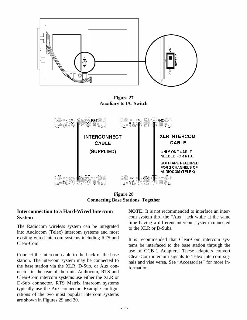
Figure 27Auxiliary to I/C Switch
Figure 28Connecting Base Stations Together
Interconnection to a Hard-Wired IntercomSystem
The Radiocom wireless system can be integratedinto Audiocom (Telex) intercom systems and mostexisting wired intercom systems including RTS andClear-Com.
Connect the intercom cable to the back of the basestation. The intercom system may be connected tothe base station via the XLR, D-Sub, or Aux con-nector in the rear of the unit. Audiocom, RTS andClear-Com intercom systems use either the XLR orD-Sub connector. RTS Matrix intercom systemstypically use the Aux connector. Example configu-rations of the two most popular intercom systemsare shown in Figures 29 and 30.
NOTE: It is not recommended to interface an inter-com system thru the “Aux” jack while at the sametime having a different intercom system connectedto the XLR or D-Subs.
It is recommended that Clear-Com intercom sys-tems be interfaced to the base station through theuse of CCB-1 Adapters. These adapters convertClear-Com intercom signals to Telex intercom sig-nals and vise versa. See “Accessories” for more in-formation.

Figure 29Example Interface to an Audiocom (Telex) Intercom System

Figure 30Example Interface to an RTS Intercom System

Auxiliary Audio Connection
The 6 pin telephone jack (RJ-11) may be used tosupply audio into and out of the base station. RTSMatrix type intercoms may be interfaced to the basestation through this jack.
Since audio is not “Channelized” through this jack,the audio channel switch has no effect on the audiopassed through the jack. The audio will be heard onboth channels 1 and 2 equally, audio generated bythe BTR on channels 1 or 2 will be sent to theAuxiliary Jack.
Figure 31Auxiliary Jack
Power Connection
Insure the Power ON/OFF Switch on the front ofthe base station is in the “OFF” position. Connectthe supplied AC power supply cord to the receiverat the socket labeled “POWER”. Connect the powersupply unit to an AC outlet supplying 105 to 125VAC, 60 Hz.
Figure 32Connecting the Power Supply
Dummy Load
In the case where a wired intercom will not be usedwith the base station or only one of the audio chan-nels are connected to the unit, it is important that thedummy load(s) (supplied) be installed.
I/C Switch = Set for TelexTelex dummy loads should be plugged into bothXLR ports if a wired Telex intercom system is notbeing used. A single Telex dummy load should beplugged into the unused channel’s XLR port if onlyone channel is connected to an intercom system.
I/C Switch = Set for RTSRTS dummy load should be plugged into one of theXLR ports if an RTS intercom system is not beingused.
NOTE: If the dummy load is not placed properly,an annoying squeal may result that may cause dam-age to the ears.

Beltpack Set-Up
Headset Connection
Insert the headset/microphone into the connector onthe bottom on the unit. See the headset connectiondiagram (Figure 8) if a unit other than Telex headsetis used.
Figure 33Connecting Headset
RF Transmit/Receive Channel Switches
Allows the user to select which of the two RF chan-nels the unit is on. The transmit channel selected,either “A” or “B”, is the frequency of the beltpack’stransmitter.
The receiver channel selected, either “A” or “B”, isthe frequency the beltpack’s receiver is at. The fre-quencies are listed on the label which is locatedunder the beltpack’s battery pack.
The base station’s transmit frequency mustmatch the beltpack’s receive frequency. Also thebase station’s receiver must match the beltpack’stransmit frequency. Typically the base stationswitches are both set to “A” or both to “B” andthe beltpacks are set to match.
Figure 34RF Channel Switches and RF Transmit Mode
Switch
RF Transmit Mode Switch
Allows the operator to select two different types oftransmitting modes; Push-to-talk or Push-to-trans-mit. For most operations, place the transmitterswitch in the “Push-to-talk" mode.
In the “Push-to-talk” mode the RF transmitter willbe on at all times regardless of whether the talkswitch is on or off.
In the “Push-to-transmit” mode, the transmitter willbe on only when the talk button is activated. Thetransmitter will be turned off when the talk button isdeactivated.
Code Switch (TR-600C Only)
Allows the operator to select over 65,000 ciphercodes. The beltpack’s code must match the base sta-tion’s code for audio recovery. Any combination ofletters and/or numbers may be selected except 0000.The data is unencrypted when the setting is 0000.
Figure 35Code Switch

Battery Installation
Insure that the OFF/ON volume control knob isturned OFF. Press down the battery release latch andremove battery pack. Pack slides off in opposite di-rection. Replace batteries as follows:
Figure 36Battery Installation
1. Open the battery pack by inserting fingernail and lifting as shown.
2. Pull battery strap to remove low ordead batteries.
3. Load new batteries with negative end against the spring.
4. Start loading at hinged end of case.
5. Be sure strap goes under batteries and over the top of the ribs.
6. Tuck end of strap under door when closing.

Pre-Walk-Thru Checklist
Following the instructions fully to this point youhave successfully completed the following check-list:
Located the base station properly.
Connected power to base station transceiver.
Connected the 1/2-wave antennas to the basestation. Check frequency range of the antennawith the frequency of the base station by cor-rectly matching color codes.
For a large system in which a splitter/com-biner (SC-600) is used, make sure the antennacables are connected to the correct ports andthat the main antennas are connected to themarked SC-600 ports.
Set RF transmit and receive switches on thebase stations(s) to match their respective belt-packs.
Set transmit mode switch on base station.
Set wired intercom type correctly.
Set audio channel correctly.
Set Telex switch properly.
Set Code Switch to a unique code thatmatches the beltpack. (BTR-600C only)
Connected headsets to base stations (ifneeded) and all beltpacks.
Connected the base station to any auxiliaryaudio, intercom, or external speaker if needed.
Installed batteries in the beltpack.
If you missed any of the above instructions,go back and complete that instruction beforegoing on.

System OperationBase Station Operation
Power
If you have followed the instructions until this pointyou should now be ready to turn both the beltpackand the base station “ON”
Place the power switch on the base station in the“ON” position. The green power on indicator LEDshould illuminate.
Figure 37Base Station Power Switch
Push-to-Talk/Lock-to-Talk Switch
To enable the talk function on the base station pressand hold down on the talk button and begin talking.Releasing the talk button will discontinue the micro-phone audio. For continuous talk, quickly press andrelease the talk button. This enables the talk func-tion as long as you want. To release the talk functionpress and release the talk button once more and thetalk function will cease.
NOTE: The talk LED will be illuminated whereverthe talk function is activated.
Local Headset Volume
Adjust the volume control on the base station byrotating the Volume control either clockwise orcounterclockwise as required for comfortable listen-ing volume.
Figure 38Push-to-Talk/Lock-to-Talk Switch and Local
Headset Volume
Microphone Gain
The microphone gain of the local headset may needto be adjusted for various audio conditions. Thetalk/overmodulation (OM) LED should be green ifthe local headset microphone has been activated.This LED will turn red when Mic Gain is too highand will need to be turned down. If the LED doesnot flash red at all and the audio is low, the gainmay need to be turned up. The gain should be ad-justed so the LED flashes red only on loudestspeech.
Using the plastic screwdriver (supplied), adjust thecontrol appropriately. Note that the volume heardcan also be adjusted by changing the spacing be-tween the microphone and your mouth.
Figure 39Adjusting Microphone Gain

Dual Listen Level
This control is related to the dual listen switches. Itcontrols the level of the audio mix. For more infor-mation on the dual listen switches, refer to the“Base Station Set-Up” section.
Figure 40Dual Listen Level Control
Intercom Level
I/C INAdjusts the level of the Intercom system’s audiointo the base station. The Intercom “IN” controlshould be adjusted so the intercom LED flashes redon loudest speech over the intercom system.
I/C OUTAdjusts the level of the base station’s audio out tothe intercom system. The intercom “OUT” controlshould be adjusted so that its audio on the intercomsystem is equal in level to the other intercom de-vices on the intercom system. A way to adjust thislevel is to have someone talk into the base stationwith a local headset while someone else listens tothe audio over the intercom system via another in-tercom device.
Auxiliary Level
These controls should be placed fully counter-clock-wise unless the Aux Jack is being used. Noise canbe added to the system if these controls are turnedup without a connection to the Aux. Jack.
Aux INAdjusts the level of the auxiliary input audio to thebase station. The auxiliary “IN” control should beadjusted so that the LED flashes red on loudestspeech. The Aux. switch controls whether the basestation’s auxiliary input audio is ”ON" or “OFF”.
Aux OUTAdjusts the level of the base station’s audio out tothe auxiliary connector. The auxiliary “OUT” con-trol should be adjusted so that its audio is equal toother devices on the auxiliary system. The base sta-tion’s audio is always supplied to the auxiliary jackregardless of the auxiliary switch position.
Figure 41Intercom Level Controls, AuxiliaryLevel
Controls, and Sidetone Level Controls
Sidetone Level
Local SidetoneThis control adjusts the voice feedback to the ear-phone of a headset plugged into the base station.
Beltpack SidetoneThe beltpack control adjusts the voice feedback tothe earphone of the beltpack’s headset.
NOTE: “Mirror Image” beltpacks have the abilityto communicate beltpack to beltpack direct. Thebelpack sidetone on this version is controlled by alevel control on the beltpack, see Figure 51. If abase station is used with one of these special belt-packs, then its beltpack sidetone control would haveno effect on the beltpack.

Beltpack Operation
Power/Local Headset Volume
You should now be ready to turn the beltpack “ON”.Rotate the OFF/ON Volume Control Switch on thebeltpack clockwise to turn the unit on.
Figure 42Off/On Volume Control Switch
Battery Check
As you rotate the OFF/ON volume control knobclockwise to turn the unit on, note that the batteryLED (Labeled “BAT/O.M.”) should flash one timeon good batteries. Poor batteries will cause the LEDto be illuminated continuously and a bad or unus-able battery will not cause any illumination at all.
Figure 43Low Battery and Overmodulation Indicator
LED
Push-to-Talk/Lock-to-Talk
To enable the talk function on the beltpack press andhold down on the talk button and begin talking. Re-leasing the talk button will discontinue the micro-phone audio. For continuous talk, quickly press andrelease the talk button. This locks on the talk func-tion. To release the talk function press and releasethe talk button once.
NOTE: The talk LED will be illuminated wheneverthe talk function is activated.
Figure 44Push-to-Talk/Lock-to-Talk Switch
Microphone Gain
The microphone gain of the beltpack’s headset mayneed to be adjusted for various audio conditions.The Battery/Overmodulation (O.M.) LED will flashred when Mic Gain is too high and will need to beturned down. If the LED does not flash red at all,and the audio from the unit sounds low, then thegain may need to be turned up. The gain should beadjusted so the LED flashes red only on loudestspeech.
Using the plastic screwdriver (supplied), adjust thecontrol appropriately. Note that the volume heardcan also be adjusted by changing the spacing be-tween the microphone and your mouth.

Figure 45Microphone Gain
Sidetone Level
Regular TR beltpacks have their sidetone controllocated on their respective base stations (See thesidetone level part of the base station “OperationSection”).
Specially ordered beltpack to beltpack (Mirror Im-age) direct communication units have their sidetonecontrolled by a control on the beltpack. To adjustthe voice feedback to the earphone (sidetone) ofthese units, simply turn the control until the sidetoneis at a comfortable level.
Figure 46Sidetone Level Control

Example System Configurations
Single Base Station Audiocom (Telex) System
The audio out RCA jack on the back of this unit isused for the public address system. The unusedAudiocom channel must be terminated to avoid loudfeedback if audio channel two was switched to bythe beltpack.
The audio out of the base station’s RCA jack is theaudio channel currently switched to at the BTR-500.
Figure 47Example single BTR-500 Audiocom System used at a Shooting Range

Single Base Station RTS System
Figure 48Example Single BTR-500 RTS System used at a Small Play Production

Six Base Station RTS System
Figure 49Example of Six BTR-500 RTS Systems used by a Production Unit

Figure 50Example of an Eight BTR-600C Audiocom(Telex) System being used by a Football Team
Eight Base Station Telex System

Beltpack to Beltpack System
The following is an example of a beltpack to belt-pack system. The two operators need to be in con-stant, full-duplex communication with each other ina noisy paper press environment.
Figure 51Example of a TR-500 System used at a Publishing Firm
Single Beltpack to Single Beltpack System

System Walk-Thru
Now that you have successfully “set up” your TelexWireless Intercom System and turned on any auxil-iary equipment you are ready to test the overall per-formance by “Walking” the Telex system throughthe areas in which you will be using it.
Before you begin your walk-thru, check the follow-ing:
Beltpack Battery Check.
Set microphone gain in both the beltpack andthe base station.
Check that the push-to-talk switch is engagedin the lock-to-talk position. LED will be illu-minated.
I/C Level “IN” and “OUT” are set to an ap-propriate level and not turned to zero.
Sidetone local and beltpack levels are set toan appropriate level.
The “system walk-thru” can detect problems ofweak signal strength caused by:
Poor antenna location
Wrong antenna for receiver and/or transmitter.
RF “Trouble Spots”
Operating distance beyond system capability.
Old or used batteries in the TR-500/600
Under normal conditions the indicator LED on thebase station’s beltpack should always be lit whentheir beltpacks are transmitting. “Weak Signal” con-ditions will result in flashing, or the complete lossof this Carrier LED.
In 99% of all instances you will set up your TelexWireless Intercom System, walk it through andachieve error-free performance. If in the rare in-stance your Telex system does not “pass” duringyour walk-thru evaluation, refer to the section ofthis manual which deals with System Troubleshoot-ing.

TROUBLESHOOTING
Reread the sections of this manual to make sure youhave completed system set-up properly
If you are unable to solve the problem, contact thedealer from whom you purchased the system forassistance.
PROBLEM SOLUTION
DISTORTION - System’s audio quality seemsdistorted at medium to high input levels.
Reduce microphone gain by adjustingmicrophone gain control.
HISS - System seems to produce a “hiss” which isundesirable.
Check the gain setting on all beltpacks and thebase. They may be too low.
LOW OUTPUT - System produces a low outputlevel.
Check the gain setting on both the beltpacks andthe base. They may be too low.
FEEDBACK - Moving around area of useproduces “squeal” or “howl” in various locationsusing ext. speakers.
Reduce the gain settings on both the beltpacks andthe base. They may be too high.
DROPOUTS - When moving around the area ofuse there seems to be locations where the signal“swooshes” or completely disappears.
Make sure both antennas on the base areconnected and follow the location suggestions.Change the location of the base unit and antennasor avoid the bad areas with the remote beltpacks.
INTERFERENCE - System picks up signalsother than wireless Intercoms.
Make sure the Telex beltpack is turned on - thiswill usually eliminate the interfering signal. If notusing a beltpack, make sure the transmit modeswitch at the base is in the off position.
If problems persist with the beltpack on, you willprobably need to change frequency channels.Make sure the base channel switch matches thebeltpack.
NO AUDIO from BASE or BELTPACKheadsets.
Check Transmitter switch on base, use CONT orREMOTE position. Check push-to-talk function -is the switch ON. Make sure beltpack batteries areOK.

Tech Tips
Codes Settings and the BTR600C
While the BTR-600C and corresponding TR-600Chave over 65,000 different codes that may be se-lected by the user, there are actually over 16 milliondifferent codes in the units. The microprocessor ineach base station and corresponding beltpack hastwo unique numbers programmed into them fromthe factory. The external four code switch settingsare used in conjunction with these two internal, non-accessible, numbers to encrypt and decrypt audiosent to and from the units.
Frequency Interaction
Unfortunately, radio frequency (RF) channels can-not be randomly selected for use in radio devices.They must be selected to avoid known frequenciesin use, FCC restrictions on the location of devices,and even interference between your own RF de-vices. The channels selected by Telex for Radiocomsystems are chosen to minimum possible interfer-ence. This is why it is always important to informTelex about frequencies of other Radiocom or otherRF devices that will be used with any additionalRadiocom equipment ordered.
Microphone Gain Adjustment
The microphone gain controls on the base station and beltpack are set to mid-levels by the factory. In mostcases this setting will work fine and only on loudest speech will the overmodulation (OM) indicator light.However, in environments where the background noise is loud or the user has a strong/quiet voice, thegain control will need to be adjusted. In Figure 52 the gain is set correctly. The user’s root-mean-square(RMS) sound level is well below the OM threshold and only on a few loud peaks does his or her voiceflash the OM indicator light. Figure 53 displays the same gain setting as in Figure 52, but brought into ahigh noise environment. The user’s voice now lights the OM indicator over half the time he or she speaksdue to the higher noise plus the user speaking louder. The result on the system is distortion with possible“clipping” on louder speech. The microphone gain must be reduced. The same applies to a user with apowerful voice. If someone sets the system mic gain to their voice and user has a much stronger voice,then the gain will need to be reduced, even if the background noise is the same.
Always remember to set the microphone gain based on the situation and location in which the equipmentwill be used. If the equipment is used on the field during a football game, set the gain based upon a loudstadium, NOT the quiet stadium 2 hours before a game. If a production studio user has a quiet voice, setthe gain to their voice and NOT the stage hand’s loud voice who helped set up the system.
Figure 52Low Noise Environment
Microphone Gain Set Correctly
Figure 53High Noise Environment
Microphone Gain Set Too High

RTSInput Impedance: ..................................... 200 5%Output Level: ............................0.775 Vrms nominalBridging Impedance:...................................... >10k
Send: .................. 20kHz 100 Hz, 240 mVrmsReceive: ............. 20kHz 800 Hz, 100 mVrms
Power Voltage: ........................... 28.0 VDC nominal
Intercom Systems Specifications
AudioCom/TelexInput Impedance: ................................... 300 10%Output Level: ................................1.0 Vrms nominalBridging Impedance:...................................... >10k
Send: .........20kHz 100 Hz, 0.5 mVrms Receive: ............. 20kHz 800 Hz, 100 mVrms
Power Voltage: ........................... 24.0 VDC nominal
Clear-ComInput Impedance: ..................................... 150 5%Output Level:...................................200 Vrms 10%Bridging Impedance: ......................................>10k
Send:................................................ 12 3 VDCReceive: ................................4 VDC Minimum
Power Voltage: ............................30.0 VDC nominal
Battery Information
Improper battery selection, use, installation and careare the cause of numerous wireless system failures.
Alkaline Batteries: Alkaline batteries such as Mal-lory’s DURACELL or Eveready’s ENERGIZERprovide the most reliable operation in wireless trans-ceivers. Typical battery life of fresh alkaline batter-ies is 12 hours. The use of low cost carbon-zincbatteries is NOT recommended.
Nickel-Metal Hydride Batteries: These batteriescan save you money in the long run, as they can berecharged. Typical battery life is 8 to 9 hours, whichis about 70% of the length of time alkaline batterieslast.

Accessories and Replacement Parts
ALP-600520-760 MHz Bi-Directional Log Periodic AntennaIncludes mounting hardware and 10 feet (3 meters)of coaxial cable with TNC Connectors Order No. 878896
Antenna Cables: Special low loss antenna cableswith TNC Connectors.
1/2-Wave Antenna
ALP-450450-900 MHz Log Periodic AntennaIncludes mounting hardware and 10 feet (3 meters)coaxial cable with TNC connectors Order No. 71147000
CCB-1 Interface Device
Order No. 96230-000
Model No. Length Order No.
CXU-10 10 Ft. (3 meter) 690419CXU-25 25 Ft. (7.6 meter) 71151-025
CXU-50 50 Ft. (15 meter) 71151-050
CXU-75 75 Ft. (23 meter) 71151-075
CXU-100 100 Ft. (30 meter) 71151-100
Model No. Part No. Band Color Frequency
CLA-1 870658-1 Blue 520-564.9 MHz
CLA-2 870658-2 Yellow 565-614.9 MHz
CLA-3 870658-3 Red 615-659.9 MHz
CLA-4 870658-4 White 660-689.9 MHz
CLA-5 870658-5 Green 690-724.9 MHz
CLA-6 870658-6 Orange 725-760 MHz

CUSTOMER SERVICE INFORMATION

FCC INFORMATION


![AudioCom Training rev3 - textfiles.compdf.textfiles.com/manuals/STARINMANUALS/Telex Intercom/Manuals... · 1 Telex Intercom 1]Small System Intercom AudioCom RTS-TW 2] Large System](https://static.fdocuments.us/doc/165x107/5b25fa067f8b9ad4348b517a/audiocom-training-rev3-intercommanuals-1-telex-intercom-1small-system.jpg)


