Clear-Com Eclipse Beltpack Manual
74
USER MANUAL ECLIPSE DIGITAL WIRELESS
Transcript of Clear-Com Eclipse Beltpack Manual
U S E R M A N U A L
ECLIPSE DIGITAL WIRELESS

Eclipse Digital Wireless Beltpack Instruction Manual © 2007 Vitec Group Communications Ltd. All rights reserved.
Part Number 810376Z Rev. 2
Vitec Group Communications, LLC. 850 Marina Village ParkwayAlameda, CA 94501U.S.A
Vitec Group Communications Ltd7400 Beach DriveCambridge Research ParkCambridgeshireUnited KingdomCB25 9TP
Vitec Group CommunicationsRoom 1806, Hua Bin BuildingNo. 8 Yong An Dong LiJian Guo Men Wai AveChao Yang DistrictBeijing, P.R. China 100022
® Clear-Com, CellCom/FreeSpeak and the Clear-Com Communication Systems logo are registered trademarks of The Vitec Group plc.

Vitec Group Communications
SOFTWARE LICENSE
IMPORTANT: CAREFULLY READ THE FOLLOWING BEFORE USING THIS SOFTWARE. USING THE SOFTWARE INDICATES YOUR ACKNOWLEDGMENT THAT YOU HAVE READ THE FOLLOWING AND AGREE TO ITS TERMS.
IF YOU DO NOT AGREE, RETURN THE SOFTWARE COMPLETE TO VITEC GROUP COMMUNICATIONS LIMITED OR CANCEL THE INSTALLATION.
THIS IS YOUR PROOF THAT YOU HAVE A VALID LICENSE. PLEASE TREAT IT AS VALUABLE PROPERTY.
VITEC GROUP COMMUNICATIONS LIMITED OR VITEC GROUP COMMUNICATIONS, INC., as the case may be (hereinafter referred to as “VGC”), offers you this storage media containing a computer program and files (the “SOFTWARE”) and offers to grant to you a non-exclusive and non-transferable License to use the Software on the following terms. Any new revision or update of the Software provided by VGC to Customer under this License shall be governed by the terms and conditions of this License.
1. APPLICATIONa. These terms supersede all prior agreements representations and understandings between you the Customer and VGC and their authorised representatives relating to the subject matter hereof (i.e., the Software) but shall otherwise be subject to Vitec Group Communications Terms and Conditions, as amended from time to time. For the avoidance of doubt, in the event of conflict, these terms shall prevail. b. No variation to these terms, nor any other terms or conditions proposed by you, shall be of any effect unless recorded in a written document signed by VGC. You confirm that any statement made to the contrary by you or on your behalf shall not apply to this License.c. You confirm that you are not relying on any statement made by or on behalf of VGC, other than statements recorded in a written document signed by VGC.d. VGC and its licensors reserve all rights not expressly granted to you. VGC's licensors are intended third party beneficiaries of this Agreement and have the express right to rely upon and directly enforce the terms set forth herein.e. You agree that the Software belongs to VGC and its licensors. You agree that you neither own nor hereby acquire any claim or right of ownership to the Software or to any related patents, copyrights, trademarks
E C L I P S E W I R E L E S S C O M M U N I C A T I O N S Y S T E M i

or other intellectual property. VGC and its licensors retain all right, title and interest in and to the Software and all copies thereof at all times, regardless of the form or media in or on which the original or other copies may subsequently exist. This license is not a sale of the original or any subsequent copy.
2. COPYRIGHTa. The copyright and all other rights in the Software produced by VGC shall remain with VGC or its suppliers. You must reproduce any copyright or other notice marked on the Software on any copies that you make.
3. YOU MAY: a. Use the Software only at a single site location. If you wish to use the Software at more than one site you must contact VGC and if required purchase further Licenses;b. Make one copy of the Software for archival or back-up purposes, and;c. Transfer the Software to an end user of a VGC product, only if you have made it clear to VGC that you are not the end user and you assign all of your rights under this License and make no use of the Software yourself.
4. YOU MAY NOT:a. Use the Software or make copies of it except as permitted in this License;b. Publish or distribute the computer images, sound files or fonts included with the Software as computer images, sound files or fonts;c. Translate, reverse engineer, decompile or disassemble the Software, except to the extent the foregoing restriction is expressly prohibited by applicable law;d. Rent, lease, assign or transfer the Software except as set out above; ore. Modify the Software or merge all or any part of the Software in another program.
5. TERM:a. This License shall continue for as long as you use the Software. However, it will terminate if you fail to comply with any of its terms or conditions. You agree, upon termination, to destroy all copies of the Software. The Limitations of Warranties and Liability set out below shall continue in force even after any termination.
6. LIMITED WARRANTY:a. VGC warrants that the storage media in this Software will be free from defects in materials and workmanship for 90 days from the date you acquire it. If such a defect occurs, return it to us at the address below and we will replace it free. This remedy is your exclusive remedy for breach of this warranty.b. After the initial 90 days, THE SOFTWARE IS PROVIDED "AS IS" WITHOUT WARRANTY OF ANY KIND EITHER EXPRESS, IMPLIED OR STATUTORY, INCLUDING BUT NOT LIMITED TO THE IMPLIED WARRANTIES OF MERCHANTABILITY, FITNESS FOR A
E C L I P S E W I R E L E S S C O M M U N I C A T I O N S Y S T E Mii

PARTICULAR PURPOSE, PERFORMANCE, ACCURACY, RELIABILITY, OR NON-INFRINGEMENT OF THIRD-PARTY INTELLECTUAL PROPERTY RIGHTS. This constitutes an essential part of this License.
7. LIMITATION OF LIABILITY:a. For the avoidance of doubt, all conditions imposed by law covering matters such as fitness for purpose, compliance to description, negligence and quality are expressly excluded from this agreement and you agree to accept the foregoing warranty in lieu of all such items. b. IN NO EVENT SHALL VGC BE LIABLE FOR ANY LOSS OF PROFITS, LOSS OF BUSINESS, LOSS OF DATA OR USE OF DATA, INTERRUPTION OF BUSINESS, OR FOR INDIRECT, SPECIAL, INCIDENTAL, EXEMPLARY, MULTIPLE, PUNITIVE OR CONSEQUENTIAL DAMAGES OF ANY KIND, WHETHER BASED ON CONTRACT, TORT (INCLUDING WITHOUT LIMITATION, NEGLIGENCE), WARRANTY, GUARANTEE OR ANY OTHER LEGAL OR EQUITABLE GROUNDS, EVEN IF VGC HAS BEEN ADVISED OF THE POSSIBILITY OF SUCH DAMAGES. c. The warranty is personal to you (or end user if you have made it clear that you are not the end user) and may not be transferred (except as permitted expressly above). d. VGC shall not be a liable for failure to perform any obligation to you where such failure is due to circumstances beyond VGC’s reasonable control.e. VGC offers extended warranties and, if you are not satisfied with the above, you should consider such warranties or consider separate insurance.
8. RESTRICTED RIGHTS:If this Software is acquired by or for the U.S. Government then it is provided with Restricted Rights. Use, duplication, or disclosure by the U.S. Government is subject to restrictions as set forth in subparagraph (c)(1)(ii) of The Rights in Technical Data and Computer Software clause at DFARS 252.227-7013, or sub-paragraphs (c)(1) and (2) of the Commercial Computer Software - Restricted Rights at 48 CFR 52.227-19, or clause 18-52.227-86(d) of the NASA Supplement to the FAR, as applicable. Contractor/manufacturer: Vitec Group Communi-cations Limited, 7400 Beach Drive, Cambridge, England CB25 9TP or Vitec Group Communications, LLC., 850 Marina Village Parkway, Alameda, CA 94501.
9. OTHER ISSUES:a. Any failure by VGC to insist on its strict rights under this Agreement shall not be deemed to be a waiver of those (or any other rights) and only a duly executed written release shall constitute such a waiver.b. If any of these conditions is deemed invalid or unenforceable the remainder shall be unaffected. c. VGC's dealings with you shall be governed by English law if you are resident in the EMEA region and California law if you are resident elsewhere. The federal and state courts of California for Non-EMEA
E C L I P S E W I R E L E S S C O M M U N I C A T I O N S Y S T E M i i i

Customers and English Courts for EMEA Customers shall have exclusive jurisdiction to adjudicate any dispute arising out of this Agreement.d. If any document is written in more than one language the English text shall prevail. e. Capitalized terms not defined herein shall have the meanings set forth in Vitec Group Communications' Terms and Conditions, as amended from time to time.
E C L I P S E W I R E L E S S C O M M U N I C A T I O N S Y S T E Miv

CONTENTSOPERATING THE ECLIPSE WIRELESS BELTPACK . . . . . . . . . . . . . . . . . . . 1-1Overview of the Wireless Belpack . . . . . . . . . . . . . . . . . . . . . . . . . . . . . . . . . 1-1
Beltpack Top Control Section . . . . . . . . . . . . . . . . . . . . . . . . . . . . . . . . . . 1-2
Talk Knobs, Channels A and B . . . . . . . . . . . . . . . . . . . . . . . . . . . . . . . 1-2
Level-Control Lights, Channels A and B . . . . . . . . . . . . . . . . . . . . . . . . 1-3
Talk/Listen Lights, Channels A and B . . . . . . . . . . . . . . . . . . . . . . . . . . 1-3
Answer-Back Lights . . . . . . . . . . . . . . . . . . . . . . . . . . . . . . . . . . . . . . . . 1-3
Beltpack Front/Display Section . . . . . . . . . . . . . . . . . . . . . . . . . . . . . . . . . 1-3
Backlit LCD Display . . . . . . . . . . . . . . . . . . . . . . . . . . . . . . . . . . . . . . . 1-4
Left and Right Scroll Buttons . . . . . . . . . . . . . . . . . . . . . . . . . . . . . . . . 1-4
Enter/Answer-Back Button . . . . . . . . . . . . . . . . . . . . . . . . . . . . . . . . . . 1-4
Beltpack Rear/Battery Section . . . . . . . . . . . . . . . . . . . . . . . . . . . . . . . . . . 1-4
Power Button . . . . . . . . . . . . . . . . . . . . . . . . . . . . . . . . . . . . . . . . . . . . 1-4
Battery Case. . . . . . . . . . . . . . . . . . . . . . . . . . . . . . . . . . . . . . . . . . . . . . 1-5
Belt Clip . . . . . . . . . . . . . . . . . . . . . . . . . . . . . . . . . . . . . . . . . . . . . . . . 1-5
Beltpack Bottom Connector Section . . . . . . . . . . . . . . . . . . . . . . . . . . . . . 1-5
Data Connector. . . . . . . . . . . . . . . . . . . . . . . . . . . . . . . . . . . . . . . . . . . 1-5
Headset Connector . . . . . . . . . . . . . . . . . . . . . . . . . . . . . . . . . . . . . . . . 1-6
Battery Recharger Connector. . . . . . . . . . . . . . . . . . . . . . . . . . . . . . . . . 1-6
Beltpack Turn-On Sequence . . . . . . . . . . . . . . . . . . . . . . . . . . . . . . . . . . . 1-6
Beltpack Turn-Off Sequence . . . . . . . . . . . . . . . . . . . . . . . . . . . . . . . . . . . 1-6
Powering the Eclipse Beltpack . . . . . . . . . . . . . . . . . . . . . . . . . . . . . . . . . . 1-7
Registering Beltpacks with the Matrix . . . . . . . . . . . . . . . . . . . . . . . . . . . . 1-8
Accessing the Talk/Listen Paths on the Eclipse Beltpack . . . . . . . . . . . . . . . . 1-8
Setting and Adjusting Listen Levels . . . . . . . . . . . . . . . . . . . . . . . . . . . . . 1-10
Headset Limiter . . . . . . . . . . . . . . . . . . . . . . . . . . . . . . . . . . . . . . . . . . . . 1-10
Using the Beltpack Answer-Back Functions . . . . . . . . . . . . . . . . . . . . . . . 1-11
Beltpack Menu Options . . . . . . . . . . . . . . . . . . . . . . . . . . . . . . . . . . . . . . . 1-11
Alarm Options. . . . . . . . . . . . . . . . . . . . . . . . . . . . . . . . . . . . . . . . . . . . . 1-11
Low Battery Alarm . . . . . . . . . . . . . . . . . . . . . . . . . . . . . . . . . . . . . . . 1-11
Low Signal Alarm . . . . . . . . . . . . . . . . . . . . . . . . . . . . . . . . . . . . . . . . 1-12
Audio Options. . . . . . . . . . . . . . . . . . . . . . . . . . . . . . . . . . . . . . . . . . . . . 1-12
Headphone-Off Level Option . . . . . . . . . . . . . . . . . . . . . . . . . . . . . . . 1-12
Page Lock Option . . . . . . . . . . . . . . . . . . . . . . . . . . . . . . . . . . . . . . . . 1-12
Headphone Limiter Option. . . . . . . . . . . . . . . . . . . . . . . . . . . . . . . . . 1-12
Microphone Type Option . . . . . . . . . . . . . . . . . . . . . . . . . . . . . . . . . . 1-13
Microphone Level Option . . . . . . . . . . . . . . . . . . . . . . . . . . . . . . . . . . 1-13
E C L I P S E W I R E L E S S C O M M U N I C A T I O N S Y S T E M i

Headset Options . . . . . . . . . . . . . . . . . . . . . . . . . . . . . . . . . . . . . . . . . 1-13
View Status . . . . . . . . . . . . . . . . . . . . . . . . . . . . . . . . . . . . . . . . . . . . . . . 1-13
Role Information . . . . . . . . . . . . . . . . . . . . . . . . . . . . . . . . . . . . . . . . . 1-13
Beltpack Version . . . . . . . . . . . . . . . . . . . . . . . . . . . . . . . . . . . . . . . . . 1-13
Beltpack ID . . . . . . . . . . . . . . . . . . . . . . . . . . . . . . . . . . . . . . . . . . . . . 1-13
RF Carrier Mask . . . . . . . . . . . . . . . . . . . . . . . . . . . . . . . . . . . . . . . . . 1-14
Connection Info . . . . . . . . . . . . . . . . . . . . . . . . . . . . . . . . . . . . . . . . . 1-14
Adjust Contrast . . . . . . . . . . . . . . . . . . . . . . . . . . . . . . . . . . . . . . . . . . 1-14
PROGRAMMING AT THE BELTPACK . . . . . . . . . . . . . . . . . . . . . . . . . . 2-1Introduction to Programming on the Beltpack . . . . . . . . . . . . . . . . . . . . . . . 2-1
Selection of Key and Page . . . . . . . . . . . . . . . . . . . . . . . . . . . . . . . . . . . . . . . 2-1
Master Volume Control . . . . . . . . . . . . . . . . . . . . . . . . . . . . . . . . . . . . . . . . . 2-2
Beltpack Programming - Menu Map . . . . . . . . . . . . . . . . . . . . . . . . . . . . . . . 2-2
Main Programming Menu . . . . . . . . . . . . . . . . . . . . . . . . . . . . . . . . . . . . . . . 2-2
Top Level Menu . . . . . . . . . . . . . . . . . . . . . . . . . . . . . . . . . . . . . . . . . . . . 2-3
Settings Menus . . . . . . . . . . . . . . . . . . . . . . . . . . . . . . . . . . . . . . . . . . . . . . . 2-4
The Headphone Menu . . . . . . . . . . . . . . . . . . . . . . . . . . . . . . . . . . . . . . . 2-5
Adjust Contrast . . . . . . . . . . . . . . . . . . . . . . . . . . . . . . . . . . . . . . . . . . . . . 2-6
The Alarm Options Menu . . . . . . . . . . . . . . . . . . . . . . . . . . . . . . . . . . . . . 2-6
Switching the Low Battery Alarm ON and OFF . . . . . . . . . . . . . . . . . . . . 2-7
Switching the Low Signal Strength Alarm ON and OFF . . . . . . . . . . . . . . 2-7
The Vibrate Alert Menu . . . . . . . . . . . . . . . . . . . . . . . . . . . . . . . . . . . . . . 2-8
The Microphone Menu . . . . . . . . . . . . . . . . . . . . . . . . . . . . . . . . . . . . . . . 2-8
Set Factory Defaults. . . . . . . . . . . . . . . . . . . . . . . . . . . . . . . . . . . . . . . . . 2-10
Button Options Menu. . . . . . . . . . . . . . . . . . . . . . . . . . . . . . . . . . . . . . . . . 2-10
Keylock . . . . . . . . . . . . . . . . . . . . . . . . . . . . . . . . . . . . . . . . . . . . . . . . . . 2-11
Tap Latch . . . . . . . . . . . . . . . . . . . . . . . . . . . . . . . . . . . . . . . . . . . . . . . . 2-11
PTT Configuration . . . . . . . . . . . . . . . . . . . . . . . . . . . . . . . . . . . . . . . . . 2-12
The Status (Information) Menu. . . . . . . . . . . . . . . . . . . . . . . . . . . . . . . . . . 2-12
Page Options . . . . . . . . . . . . . . . . . . . . . . . . . . . . . . . . . . . . . . . . . . . . . . . . 2-15
Page Locking . . . . . . . . . . . . . . . . . . . . . . . . . . . . . . . . . . . . . . . . . . . . . . 2-15
Key Options . . . . . . . . . . . . . . . . . . . . . . . . . . . . . . . . . . . . . . . . . . . . . . 2-15
Assign Route . . . . . . . . . . . . . . . . . . . . . . . . . . . . . . . . . . . . . . . . . . . . . . 2-17
Latch Latch . . . . . . . . . . . . . . . . . . . . . . . . . . . . . . . . . . . . . . . . . . . . . . . 2-18
Talk/Listen Menu . . . . . . . . . . . . . . . . . . . . . . . . . . . . . . . . . . . . . . . . . . 2-19
Delete a Route Assignment . . . . . . . . . . . . . . . . . . . . . . . . . . . . . . . . . . . 2-20
Delete All Assignments . . . . . . . . . . . . . . . . . . . . . . . . . . . . . . . . . . . . . . 2-21
OPERATING THE ECLIPSE TRANSCEIVER/ANTENNA. . . . . . . . . . . . . . . . . . 3-1Transceiver/Antenna . . . . . . . . . . . . . . . . . . . . . . . . . . . . . . . . . . . . . . . . . . . 3-1
E C L I P S E W I R E L E S S C O M M U N I C A T I O N S Y S T E Mi i

Transceiver/Antenna Top Panel . . . . . . . . . . . . . . . . . . . . . . . . . . . . . . . . . 3-1
Omnidirectional Antennas. . . . . . . . . . . . . . . . . . . . . . . . . . . . . . . . . . . 3-1
Transceiver Antenna Bottom/Control Panel. . . . . . . . . . . . . . . . . . . . . . . . 3-2
Serial Data Connector . . . . . . . . . . . . . . . . . . . . . . . . . . . . . . . . . . . . . . 3-2
Data Signal LED . . . . . . . . . . . . . . . . . . . . . . . . . . . . . . . . . . . . . . . . . . 3-2
Matrix Connector . . . . . . . . . . . . . . . . . . . . . . . . . . . . . . . . . . . . . . . . . 3-2
Power LED . . . . . . . . . . . . . . . . . . . . . . . . . . . . . . . . . . . . . . . . . . . . . . 3-2
DC In Power Connector . . . . . . . . . . . . . . . . . . . . . . . . . . . . . . . . . . . . 3-2
Cabling the Transceiver/Antennas . . . . . . . . . . . . . . . . . . . . . . . . . . . . . . . 3-3
Beltpack Support Capacities for Transceiver/Antennas. . . . . . . . . . . . . . . . 3-3
Coverage Areas Under Various Conditions . . . . . . . . . . . . . . . . . . . . . . . . 3-3
Transceiver/Antenna Setup Rules and Tips . . . . . . . . . . . . . . . . . . . . . . . . 3-4
Transceiver/Antenna Splitter . . . . . . . . . . . . . . . . . . . . . . . . . . . . . . . . . . . . . 3-4
Splitter Front Connector Panel . . . . . . . . . . . . . . . . . . . . . . . . . . . . . . . . . 3-5
Base Connection Indicator Light . . . . . . . . . . . . . . . . . . . . . . . . . . . . . . 3-5
Matrix (Eclipse Base) Connector . . . . . . . . . . . . . . . . . . . . . . . . . . . . . . 3-5
Splitter-to-Transceiver/Antenna Signal Indicator Light . . . . . . . . . . . . . 3-5
Transceiver/Antenna Connectors. . . . . . . . . . . . . . . . . . . . . . . . . . . . . . 3-5
Splitter Rear Panel . . . . . . . . . . . . . . . . . . . . . . . . . . . . . . . . . . . . . . . . . . 3-6
Serial Data Connector . . . . . . . . . . . . . . . . . . . . . . . . . . . . . . . . . . . . . . 3-6
Power Indicator . . . . . . . . . . . . . . . . . . . . . . . . . . . . . . . . . . . . . . . . . . . 3-6
DC IN Power Connector . . . . . . . . . . . . . . . . . . . . . . . . . . . . . . . . . . . 3-6
EXP IN Connector . . . . . . . . . . . . . . . . . . . . . . . . . . . . . . . . . . . . . . . . 3-6
EXP OUT Connector . . . . . . . . . . . . . . . . . . . . . . . . . . . . . . . . . . . . . . 3-6
Connecting an Antenna Splitter to the Eclipse Base and to Transceiver/Anten-
nas. . . . . . . . . . . . . . . . . . . . . . . . . . . . . . . . . . . . . . . . . . . . . . . . . . . . . . . . . 3-6
INSTALLING A SYSTEM . . . . . . . . . . . . . . . . . . . . . . . . . . . . . . . . . 4-1Placing the Matrix . . . . . . . . . . . . . . . . . . . . . . . . . . . . . . . . . . . . . . . . . . . . . 4-1
Placing the Antennas and Splitters . . . . . . . . . . . . . . . . . . . . . . . . . . . . . . . . . 4-1
Wiring the Antennas and Splitters . . . . . . . . . . . . . . . . . . . . . . . . . . . . . . . 4-1
Determining Coverage Areas . . . . . . . . . . . . . . . . . . . . . . . . . . . . . . . . . . . 4-2
Doing a Site Survey to Determine Coverage Areas. . . . . . . . . . . . . . . . . . . . . 4-3
Testing Coverage Areas of Individual Antennas . . . . . . . . . . . . . . . . . . . . . 4-3
Testing Antenna Handoff . . . . . . . . . . . . . . . . . . . . . . . . . . . . . . . . . . . . . 4-5
Assigning Beltpacks to Coverage Areas. . . . . . . . . . . . . . . . . . . . . . . . . . . . 4-5
Conditions Affecting Coverage Areas. . . . . . . . . . . . . . . . . . . . . . . . . . . . . 4-6
E C L I P S E W I R E L E S S C O M M U N I C A T I O N S Y S T E M i i i

SPECIFICATIONS. . . . . . . . . . . . . . . . . . . . . . . . . . . . . . . . . . . . . 5-1
APPENDIX 1: DECT CARRIER FREQUENCY CHART . . . . . . . . . . . . . . . . . . 6-1
LIMITED WARRANTY . . . . . . . . . . . . . . . . . . . . . . . . . . . . . . . . . . . 7-IWarranty Period. . . . . . . . . . . . . . . . . . . . . . . . . . . . . . . . . . . . . . . . . . . . . . . 7-i
Technical Support . . . . . . . . . . . . . . . . . . . . . . . . . . . . . . . . . . . . . . . . . . . . . 7-i
Warranty Repairs and Returns . . . . . . . . . . . . . . . . . . . . . . . . . . . . . . . . . . . . 7-ii
Non-Warranty Repairs and Returns. . . . . . . . . . . . . . . . . . . . . . . . . . . . . . . . 7-ii
Extended Warranty . . . . . . . . . . . . . . . . . . . . . . . . . . . . . . . . . . . . . . . . . . . . 7-ii
Liability . . . . . . . . . . . . . . . . . . . . . . . . . . . . . . . . . . . . . . . . . . . . . . . . . . . . 7-iii
E C L I P S E W I R E L E S S C O M M U N I C A T I O N S Y S T E Mi v

FIGURESFigure 1 Safety Symbols. . . . . . . . . . . . . . . . . . . . . . . . . . . . . . . . . . . . . . . . . . . . . . . . . . . 2-ivFigure 1-1 Overview of Beltpack Functions . . . . . . . . . . . . . . . . . . . . . . . . . . . . . . . . . . 1-1Figure 1-2 Beltpack Display . . . . . . . . . . . . . . . . . . . . . . . . . . . . . . . . . . . . . . . . . . . . . . . . 1-2Figure 1-3 View of Top of Beltpack . . . . . . . . . . . . . . . . . . . . . . . . . . . . . . . . . . . . . . . . . 1-2Figure 1-4 View of Front of Beltpack. . . . . . . . . . . . . . . . . . . . . . . . . . . . . . . . . . . . . . . . 1-3Figure 1-5 View of Back of Beltpack . . . . . . . . . . . . . . . . . . . . . . . . . . . . . . . . . . . . . . . . 1-4Figure 1-6 View of Bottom of Beltpack . . . . . . . . . . . . . . . . . . . . . . . . . . . . . . . . . . . . . . 1-5Figure 1-7 Battery Discharge Characteristics . . . . . . . . . . . . . . . . . . . . . . . . . . . . . . . . . 1-7Figure 1-8 How the beltpack displays its six communication routes . . . . . . . . . . . . . . 1-9Figure 2-1 Top Level Menu Structure . . . . . . . . . . . . . . . . . . . . . . . . . . . . . . . . . . . . . . . 2-3Figure 2-2 Beltpack Settings Menu Structure . . . . . . . . . . . . . . . . . . . . . . . . . . . . . . . . . 2-4Figure 2-3 Connection Information Display . . . . . . . . . . . . . . . . . . . . . . . . . . . . . . . . . 2-14Figure 2-4 Key Options Menu Structure . . . . . . . . . . . . . . . . . . . . . . . . . . . . . . . . . . . . 2-16Figure 3-1 Eclipse Transceiver/Antenna . . . . . . . . . . . . . . . . . . . . . . . . . . . . . . . . . . . . . 3-1Figure 3-2 Eclipse Transceiver/Antenna Bottom/Control Panel . . . . . . . . . . . . . . . . . . 3-2Figure 3-3 Eclipse Splitter Front Connector Panel . . . . . . . . . . . . . . . . . . . . . . . . . . . . . 3-5Figure 4-1 A Beltpack’s Site Survey Screen. . . . . . . . . . . . . . . . . . . . . . . . . . . . . . . . . . . 4-3Figure 4-2 Mapping overlapping coverage zones . . . . . . . . . . . . . . . . . . . . . . . . . . . . . . 4-4
E C L I P S E W I R E L E S S C O M M U N I C A T I O N S Y S T E M i

E C L I P S E W I R E L E S S C O M M U N I C A T I O N S Y S T E Mi i

TABLESConnection Information . . . . . . . . . . . . . . . . . . . . . . . . . . . . . . . . . 2-14How antennas are numbered . . . . . . . . . . . . . . . . . . . . . . . . . . . . . . 4-5DECT Carrier Frequency Chart . . . . . . . . . . . . . . . . . . . . . . . . . . . . 6-1
E C L I P S E W I R E L E S S C O M M U N I C A T I O N S Y S T E M i

E C L I P S E W I R E L E S S C O M M U N I C A T I O N S Y S T E Mi i

IMPORTANT SAFETY INSTRUCTIONS
1. Read these instructions.2. Keep these instructions.3. Heed all warnings.4. Follow all instructions.5. Do not use this apparatus near water.6. Clean only with dry cloth.7. Do not block any ventilation openings. Install in accordance with the
manufacturer’s instructions.8. Do not install near any heat sources such as radiators, heat registers, stoves,
or other apparatus (including amplifiers) that produce heat. 9. Do not defeat the safety purpose of the polarized or grounding-type plug. A
polarized plug has two blades, with one wider than the other. A grounding-type plug has two blades and a third grounding prong. The wide blade or the third prong are provided for your safety. If the provided plug does not fit into your outlet, consult an electrician for replacement of the obsolete outlet.
10. Protect the power cord from being walked on or pinched particularly at plugs, convenience receptacles, and the point where they exit from the apparatus.
11. Only use attachments/accessories specified by the manufacturer. 12. Use only with the cart, stand, tripod, bracket, or table specified by the
manufacturer, or sold with the apparatus. When a cart is used, use caution when moving the cart/apparatus combination to avoid injury from tip-over.
13. Unplug this apparatus during lightning storms or when unused for long periods of time.
14. Refer all servicing to qualified service personnel. Servicing is required when the apparatus has been damaged in any way, such as power-supply cord or plug is damaged, liquid has been spilled or objects have fallen into the apparatus, the apparatus has been exposed to rain or moisture, does not operate normally, or has been dropped.
15. WARNING: To reduce the risk of fire or electric shock, do not expose this product to rain or moisture.
Please familiarize yourself with the safety symbols in Figure 1. When you see these symbols on this product, they warn you of the potential danger of electric shock if the main station is used improperly. They also refer you to important operating and maintenance instructions in the manual.
Please read and follow these
instructions before operating
this product.
M S - 7 0 4 / R M - 7 0 4 F o u r - C h a n n e l M a i n / R e m o t e S t a t i o n s i i i

Figure 1: Safety Symbols
EMC AND SAFETY
The Eclipse Wireless product meet all relevant CE, FCC, UL, and CSA specifications set out below:
EN55103-1 Electromagnetic compatibility. Product family standard for audio, video, audio-visual, and entertainment lighting control apparatus for professional use. Part 1: Emissions.
EN55103-2 Electromagnetic compatibility. Product family standard for audio, video, audio-visual, and entertainment lighting control apparatus for professional use. Part 2: Immunity.
UL 60065-7, CAN/CSA-C22.2 No.60065-3, IEC 60065-7 Safety requirements.
And thereby compliance with the requirement of Electromagnetic Compatibility Directive 2004/108/EC and Low Voltage Directive 2006/95/EC
This device complies with Part 15 of the FCC Rules. Operation is subject to the following two conditions: (1) this device may not cause harmful interference, and (2) this device must accept any interference received, including interference that may cause undesired operation.
CAUTIONRISK OF ELECTRIC SHOCK
DO NOT OPEN
This symbol alerts you to the presence of uninsulated dangerousvoltage within the product's enclosure that might be of sufficient magnitude to constitute a risk of electric shock. Do not open the product's case.
This symbol informs you that important operating and main-tenance instructions are included in the literature accompanyingthis product.
M S - 7 0 4 / R M - 7 0 4 F o u r - C h a n n e l M a i n / R e m o t e S t a t i o n si v

OPERATING THE ECLIPSE WIRELESS BELTPACK
OVERVIEW OF THE WIRELESS BELPACK
Figure 1-1: Overview of Beltpack Functions
An Eclipse wireless beltpack gives you simultaneous access to six channels of talk/listen communication, with the ability to switch among them as desired. Any or all of these six routes may be kept open during use. Incoming volume levels (“listen levels”) may be individually adjusted using the two push-to-talk knobs, so that one conversation can be monitored in the background while a primary conversation is held.
You can access six separate
audio routes from a
beltpack.
Depress the channel A or B
talk button to select an
audio route. Turn the button
to adjust volume.
1
E
C L I P S E W I R E L E S S C O M M U N I C A T I O N S Y S T E M 1 - 1
The front-panel display contains the name (label) of the beltpack user, identifies the two talk/listen labels currently selected by the user, and gives other information such as signal strength and battery level.
Figure 1-2: Beltpack Display
A 4-pin male headset connector is provided for connection with a standard Clear-Com headset or similar. The Eclipse beltpack will operate for up to 8 hours on four AA alkaline or rechargeable NiMH batteries.
BELTPACK TOP CONTROL SECTION
Figure 1-3: View of Top of Beltpack
Talk Knobs, Channels A and B
The talk knob functions as a volume control for incoming audio assigned to channels A and B. Turn the knob clockwise to increase the volume, and counterclockwise to decrease it.
1
Any or all of the beltpack’s
six audio routes may be
kept open while you talk or
listen on the beltpack.
E C L I P S E W I R E L E S S C O M M U N I C A T I O N S Y S T E M 1 - 2

To talk or listen on a channel, press and hold the knob down while speaking or listening from the headset. While you hold the knob down, your voice transmits on that channel. When you release the knob, your voice no longer transmits.
To “latch” a knob “on” for hands-free use, quickly tap the knob. Another quick tap releases the latch.
Level-Control Lights, Channels A and B
Three level-control lights are located next to each talk knob. The first light is green, the second is yellow, and the third is red. With the knob turned fully counterclockwise, only the green LED is lit to indicate low volume. Turning the knob clockwise, low audio level is heard in the headset. Turning the knob more, both the green and yellow LED’s light, and higher audio level is heard. This continues through the maximum audio level, indicated by only the red light being lit.
Talk/Listen Lights, Channels A and B
The green “listen” light blinks whenever a beltpack receives audio from a source whose label is displayed on the beltpack’s LED screen. When you press the talk button to “talk,” the green light then illuminates steadily and the red light also illuminates.
Answer-Back Lights
The green and red lights labeled “answer” illuminate when a source who is not on the beltpack’s presently selected communication routes tries to initiate a call to the beltpack. The red light flashes when a call is coming in and when the beltpack is communicating.
By pressing the answer-back button on the front of the beltpack you can answer an incoming call. The green LED then lights steadily and the red LED flashes until the conversation is ended by again pushing the answer-back button.
BELTPACK FRONT/DISPLAY SECTION
Figure 1-4: View of Front of Beltpack
2
3
4
Backlit LCD Display
Left and Right Scroll Buttons
Enter/Answer-Back Button
1
2
3
E C L I P S E W I R E L E S S C O M M U N I C A T I O N S Y S T E M 1 - 3

Backlit LCD Display
The display screen shows the various communications routes and other information relevant to the beltpack. The backlighting comes on when any action is taken with the scroll or enter buttons, and remains on for approximately 10 seconds. During the answer-back process, the label of the source is displayed in the lower center of the display.
Left and Right Scroll Buttons
When you press the left and right scroll buttons, the beltpack’s display screen scrolls to the left or right, displaying “pages” of information, and menu options on those pages. These buttons work in conjunction with the enter button, described below.
Enter/Answer-Back Button
The enter/answer-back button has two primary purposes. When you view the menus on the beltpack’s display screen, you can select an option by pressing this button and you can exit a menu by selecting the up-arrow icon. In this way, the button serves as an enter key.
During normal beltpack operation it functions as the answer-back key, with which you can activate a talk to an unassigned source when the answer-back “talk” light illuminates to indicate an incoming call (see description in “Beltpack Top Control Section” above).
BELTPACK REAR/BATTERY SECTION
Figure 1-5: View of Back of Beltpack
Power Button
1
2
3
1
E C L I P S E W I R E L E S S C O M M U N I C A T I O N S Y S T E M 1 - 4

The recessed power button is used to turn the Eclipse beltpack on and off. Press and hold the button for about three seconds to turn the unit on. To turn the unit off, again press and hold the button for about three seconds.
Battery Case
The removable battery case will hold four alkaline AA or four NiMH (nickel-metal hydride) rechargeable batteries. These batteries alternate, with the negative pole contacting the spring and the positive pole contacting the plate inside the case.
To remove the battery case, press on the top of the belt clip to lift it off the case, and with the thumb and middle or ring finger of the other hand squeeze the side tabs of the case and lift it out, slightly tilting the lower (toward the bottom of the beltpack) portion of the pack out first.
To insert the battery pack, follow the above instructions in reverse. Note that the battery case has a clip-on lower cover; make sure to put it back in place before putting the battery case back into the beltpack.
Caution: Do not put battery packs containing alkaline batteries into a recharger, or recharge them in the beltpack. Serious damage or injury could result.
Belt Clip
The belt clip is spring-loaded, with enough tension to hold the beltpack to the user’s belt and against the hip. Note that the upper portion of the rear of the beltpack, connected to the belt clip, is a separate piece; the entire belt clip assembly may be replaced in case of damage.
BELTPACK BOTTOM CONNECTOR SECTION
Figure 1-6: View of Bottom of Beltpack
Data Connector
This 3.5 mm (1/8 inch) tip-ring-sleeve (TRS) connector is used to connect the beltpack to a computer in order to identify the beltpack to the matrix during initial registration and system setup. It may also be used if an upgrade to the beltpack firmware is ever required in the future, to add new features and
2
3
Battery Recharger ConnectorData Connector1
Headset Connector2
3
1
E C L I P S E W I R E L E S S C O M M U N I C A T I O N S Y S T E M 1 - 5

capabilities. See the section “Registering the Beltpack with the Matrix” for further details.
Headset Connector
The male 4-pin headset connector provides audio pathways for the headset microphone and headset earpiece(s). This connector supports all Clear-Com and compatible headsets using female 4-pin connectors. It will support dynamic microphones.
Battery Recharger Connector
The Eclipse beltpack features an internal battery charger when you insert four AA-format NiMH batteries to power the unit. The recharger circuit includes a thermistor that senses the temperature of the battery pack to prevent overcharging. To use this internal recharger, plug in the small barrel connector on the supplied universal power supply into the beltpack connector, and then plug the supply into the local AC current. The beltpack will automatically shut off when the charging PSU is plugged into it. While it is charging, the beltpack cannot be turned on. You can only turn it on when the charging PSU is disconnected. A full charge takes approximately 3 to 4 hours depending on the battery capacity. After this time, the charger will maintain a trickle charge to keep the beltpack fully charged.
Eclipse beltpack usage time is dependent upon the batteries used. Some batteries require more charge/discharge cycles than others to reach their rated capacity.
Caution: Do not put battery packs containing alkaline batteries into a recharger, or recharge them in the beltpack. Serious damage or injury could result.
BELTPACK TURN-ON SEQUENCEAfter pressing the POWER button on the rear of the beltpack for approximately three seconds, the top control panel LEDs will flash and the display will light. The display will say “CLearCom” and “Searching...” It will briefly say “Getting Roles,” and then will go to the main user screen.
The beltpack will always begin on page 1, which has the first two communication routes assigned to the beltpack. When programming communication routes for the users in the system, it is best to put the most commonly used ones on this page.
BELTPACK TURN-OFF SEQUENCETo turn off the beltpack, press and hold the POWER button on the rear of the beltpack for about three seconds. The main screen will close, followed by a screen that says “CLearCom” and “Shutting Down.”
2
3
E C L I P S E W I R E L E S S C O M M U N I C A T I O N S Y S T E M 1 - 6
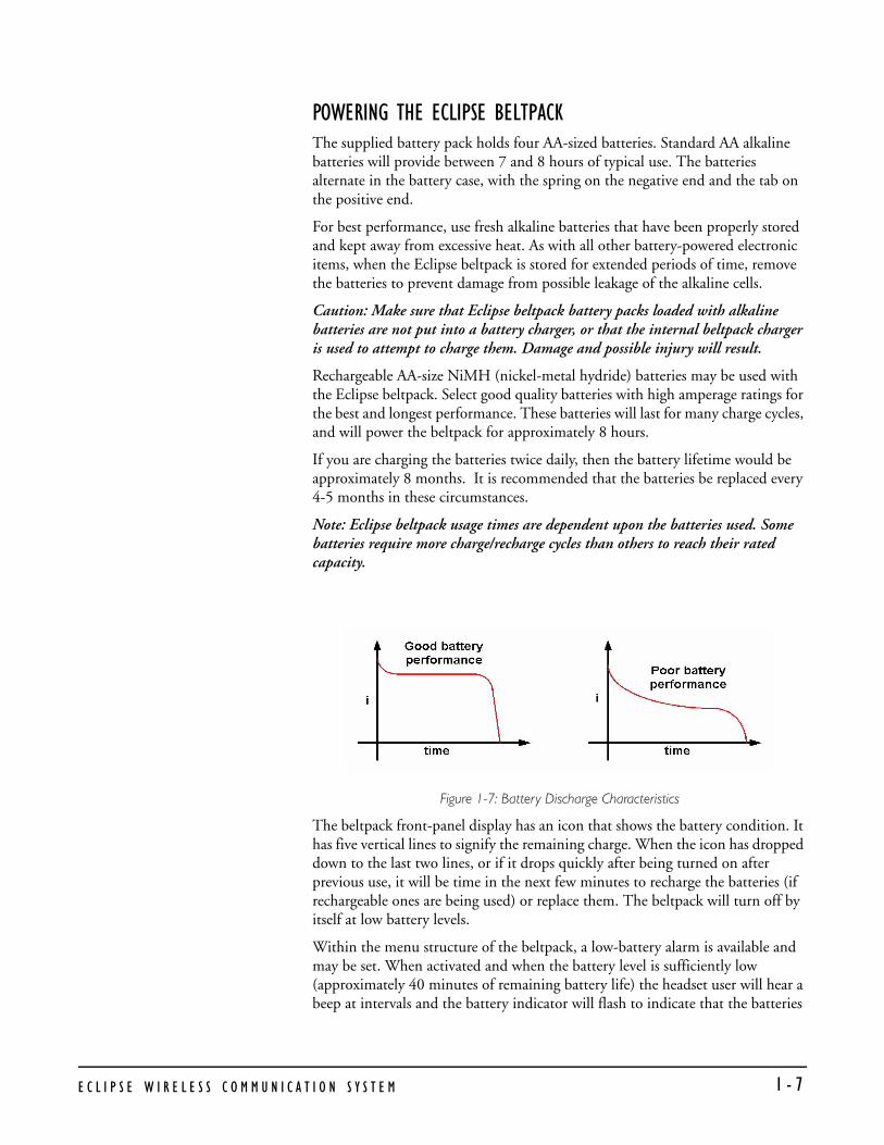
POWERING THE ECLIPSE BELTPACKThe supplied battery pack holds four AA-sized batteries. Standard AA alkaline batteries will provide between 7 and 8 hours of typical use. The batteries alternate in the battery case, with the spring on the negative end and the tab on the positive end.
For best performance, use fresh alkaline batteries that have been properly stored and kept away from excessive heat. As with all other battery-powered electronic items, when the Eclipse beltpack is stored for extended periods of time, remove the batteries to prevent damage from possible leakage of the alkaline cells.
Caution: Make sure that Eclipse beltpack battery packs loaded with alkaline batteries are not put into a battery charger, or that the internal beltpack charger is used to attempt to charge them. Damage and possible injury will result.
Rechargeable AA-size NiMH (nickel-metal hydride) batteries may be used with the Eclipse beltpack. Select good quality batteries with high amperage ratings for the best and longest performance. These batteries will last for many charge cycles, and will power the beltpack for approximately 8 hours.
If you are charging the batteries twice daily, then the battery lifetime would be approximately 8 months. It is recommended that the batteries be replaced every 4-5 months in these circumstances.
Note: Eclipse beltpack usage times are dependent upon the batteries used. Some batteries require more charge/recharge cycles than others to reach their rated capacity.
Figure 1-7: Battery Discharge Characteristics
The beltpack front-panel display has an icon that shows the battery condition. It has five vertical lines to signify the remaining charge. When the icon has dropped down to the last two lines, or if it drops quickly after being turned on after previous use, it will be time in the next few minutes to recharge the batteries (if rechargeable ones are being used) or replace them. The beltpack will turn off by itself at low battery levels.
Within the menu structure of the beltpack, a low-battery alarm is available and may be set. When activated and when the battery level is sufficiently low (approximately 40 minutes of remaining battery life) the headset user will hear a beep at intervals and the battery indicator will flash to indicate that the batteries
E C L I P S E W I R E L E S S C O M M U N I C A T I O N S Y S T E M 1 - 7

must be replaced or recharged soon. This setting is available under Alarm Options.
The Eclipse beltpack features an internal battery charger circuit, with intelligent circuitry to prevent overcharging. It is powered via the pin connector on the bottom of the beltpack, using the supplied universal power supply. A thermistor (temperature-sensing device) measures the change in temperature of the battery when charging, letting the circuit know when to cease charging the batteries.
Spare clips of four batteries are available by contacting the Sales Department.
REGISTERING BELTPACKS WITH THE MATRIXThe PC-to-Beltpack serial cable is used to register beltpacks with the PC running the Eclipse Configuration Software (ECS). It can also be used to upgrade the firmware of the beltpacks. A PC software utility program is used in conjunction with this cable to register the beltpacks.
The cable consists of a female 9-pin D type connector (PC connection) and a 3.5 mm (1.8-inch) stereo jack plug (beltpack connection). Care must be taken to select a jack plug that fits completely through the plastic surround of the connector at the bottom of the beltpack.
The data connections between the D connector and the stereo jack plug are as follows: pin 2 to tip, pin 3 to ring, and pin 5 to sleeve. Pins 1,4,6 and 8 on the PC connector are shorted together.
ACCESSING THE TALK/LISTEN PATHS ON THE ECLIPSE BELTPACKYou can access up to twelve communications routes with a beltpack. You activate a route by pressing the appropriate talk button (A or B) when the desired label appears on the beltpack’s display.
• Page 1 of the beltpack’s display screen shows the assignments for the Talk A and Talk B buttons (2 assignments).
• Page two shows the next set of assignments for the Talk A and Talk B buttons (2 assignments).
• Page three shows the next set of assignments for the Talk A and Talk B knobs (2 assignments).
• Page four shows the next set of assignments for the Talk A and Talk B knobs (2 assignments).
• Page five shows the next set of assignments for the Talk A and Talk B knobs (2 assignments).
• Page six shows the next set of assignments for the Talk A and Talk B knobs (2 assignments).
Figure 1-8 shows how the front-panel screen on a beltpack displays its six communications routes.
E C L I P S E W I R E L E S S C O M M U N I C A T I O N S Y S T E M 1 - 8
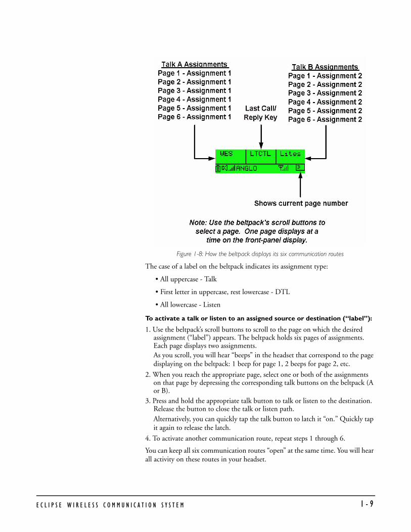
Figure 1-8: How the beltpack displays its six communication routes
The case of a label on the beltpack indicates its assignment type:
• All uppercase - Talk
• First letter in uppercase, rest lowercase - DTL
• All lowercase - Listen
To activate a talk or listen to an assigned source or destination (“label”):
1. Use the beltpack’s scroll buttons to scroll to the page on which the desired assignment (“label”) appears. The beltpack holds six pages of assignments. Each page displays two assignments. As you scroll, you will hear “beeps” in the headset that correspond to the page displaying on the beltpack: 1 beep for page 1, 2 beeps for page 2, etc.
2. When you reach the appropriate page, select one or both of the assignments on that page by depressing the corresponding talk buttons on the beltpack (A or B).
3. Press and hold the appropriate talk button to talk or listen to the destination. Release the button to close the talk or listen path. Alternatively, you can quickly tap the talk button to latch it “on.” Quickly tap it again to release the latch.
4. To activate another communication route, repeat steps 1 through 6.
You can keep all six communication routes “open” at the same time. You will hear all activity on these routes in your headset.
E C L I P S E W I R E L E S S C O M M U N I C A T I O N S Y S T E M 1 - 9

Note: Two-wire and four-wire devices can have dual talk-and-listen or just listen assignments.
SETTING AND ADJUSTING LISTEN LEVELSYou can adjust a beltpack’s incoming audio volume (“listen level”) in two ways:
• You can set the overall maximum level for the beltpack by using the beltpack menu options.
• You can adjust the incoming audio level as you talk or listen on the beltpack using the beltpack’s talk buttons.
To adjust the overall maximum “listen level” for a beltpack:
1. From the beltpack’s display, scroll to Audio Options, then Headset Options, then Master Level.
2. Select Master Level by pressing the enter button. A bar graph appears on the display.
3. Using the right and left scroll keys, adjust the level up or down as desired on the bar graph. Typically, the level control will be set to around 2/3 of maximum.
4. When the desired level is reached, press the enter button. That selection is saved in the beltpack’s memory. The display returns to the previous screen.
To adjust the listen level as you talk or listen from the beltpack:
• As you talk and listen, rotate an assignment’s talk button to increase or decrease the incoming volume level (“listen level”) for that assignment.
• As you scroll between pages, the listen levels for the various assignments remain intact. For example, rotating the talk button to increase or decrease the listen level for the first assignment on page 2 will not affect the listen level set with the same talk button on page 1 or 3.
• The three lights next to each talk button, labeled “Vol A” and Vol B,” show you the current listen level. At the lowest audio level, the green light illuminates. As the listen level increases to moderate, the yellow light illuminates, and as it increases to maximum, the red light illuminates. Note that the position of the talk button does not affect the level that is heard or indicated by the lights.
HEADSET LIMITERThe overall headset volume may also be affected by the headset limiter value set on the beltpack. See section “BELTPACK MENU OPTIONS” for more details.
E C L I P S E W I R E L E S S C O M M U N I C A T I O N S Y S T E M 1 - 1 0

USING THE BELTPACK ANSWER-BACK FUNCTIONSA beltpack’s “answer-back” key performs two functions:
The first function is to answer a call from a source whose “label” does not appear on the currently selected beltpack page.
When a source whose label does not appear on the currently selected beltpack page, but whose label does appear on a non-selected page, your beltpack’s “answer-back” light flashes, and you can hear the caller’s voice in your headset at whatever incoming volume you previously set for that label.
You can answer this call in one of two ways:
• Press the front-panel “answer-back” button on your beltpack. This establishes a return talk path to the calling beltpack. You can press and hold the button to talk or you can quickly tap the button to “latch” it on.
• Use the front-panel scroll buttons to scroll to the page where the source’s label appears and press the appropriate talk button as usual.
The second function is to call a beltpack even though it does not have your “label” assigned to it. You must have assigned the destination beltpack’s “label” to your beltpack however to make this type of call.
For example, a stage manager labeled “STMGR” has a lighting crew member’s label “LGT1” assigned to his beltpack. However, the lighting crew member does not have the stage manager’s label assigned to his beltpack.
The stage manager can call the lighting crew member in the usual way. The lighting crew member can answer the call with the “answer-back” button on his beltpack and establish a private conversation. The lighting crew member cannot however initiate a direct call back to the stage manager.
BELTPACK MENU OPTIONSThe Eclipse beltpack presents you with a number of adjustable parameters. The main categories of the adjustments are: Alarm Options, Audio Options, View Status, and Adjust Contrast accessed through the menu. To enter menu mode hold down both page buttons simultaneously until the beltpack enters menu mode (about 5 seconds). An icon of an upward pointing arrow designates EXIT or BACK, and is available on each menu page. Selecting this icon and pressing the center ENTER button takes you to the previous screen or exits to the beltpack’s main menu.
ALARM OPTIONS
Low Battery AlarmThe low-battery alarm has two settings: on and off. Using the scroll keys, select the desired setting and then press the center ENTER key.
• When you select ON, you will hear a beep at intervals in your headset to indicate that it is time to replace or recharge the belpack batteries. This will
E C L I P S E W I R E L E S S C O M M U N I C A T I O N S Y S T E M 1 - 1 1

occur when the battery level is sufficiently low (approximately 40 minutes of remaining battery life). The battery indicator will also flash.
• When you select OFF, you will not be warned of low battery level.
Low Signal AlarmThe low-signal alarm has two settings: on and off. Using the scroll keys, select the desired setting and then press the center ENTER key.
• When you select ON, you will hear a beeping in the beltpack’s headset when the beltpack is almost out of the range of the antenna, and will soon lose connection with the system.
• When the beltpack’s signal-level icon is at the second-lowest increment, you will hear one quick beep and two slightly longer beeps at approximately one-second intervals in the headset. You will hear the same beeps when you go completely out of range and connection is lost with the antenna (and the base). These beeps continue until you move into an area where the signal is stronger.
• This setting may be especially useful when you are learning to establish the coverage area for a particular location. Because the signal level when the alarm is first activated is still strong enough for conversations to happen (though possibly with occasional audio dropouts), it may not be desirable to keep this alarm on during normal operation of the system. This low signal alarm is also useful for checking out the coverage in a location when first setting up transceiver/antennas, for either a temporary or permanent installation.
• When you select OFF, the low signal alarm does not operate.
AUDIO OPTIONS
Headphone-Off Level Option This option allows you to select the signal threshold when the headphone audio “turns off.” Level settings are - 6, -12, -18, and – 70 dB. The typical setting is –70 dB, which functions as “always on.”
Page Lock OptionWhen you select the Page Lock option the page change keys no longer operate.
Headphone Limiter OptionThis option introduces a limiter into to headphone audio circuitry, to control excessive levels and resulting stress on the ear of the user. The level can be set anywhere in the range -32dBu to +16dBu using the Headphone Limiter display on the beltpack. The typical setting is –6dBu.
E C L I P S E W I R E L E S S C O M M U N I C A T I O N S Y S T E M 1 - 1 2

Microphone Type Option This option allows you to select the proper setting for the headset microphone. The available settings are Dynamic (Balanced) Mic and Dynamic (Unbalanced) Mic. For most Clear-Com and other headsets, the Dynamic (Unbal) Mic setting is proper.
Microphone Level Option This option allows you to set the level of the beltpack’s headset mic, increasing or decreasing its gain going into the system. For Type I beltpacks the gain settings are 40, 50, and 60dB, for Type II beltpacks the gain settings are 50, 55, 60 and 65dB. The typical setting is 50dB.
Headset OptionsTwo headset options are offered:
• Master Level
• Sidetone Level
The Master Level control accesses a slide bar going from “-“to “+”, and controls the overall maximum level that can be heard through the headphones. This gain control permits adjustment among headsets with different sensitivities, and for different use conditions (quiet studio versus loud live performance environment). Typical setting is 2/3 to 3/4 of the way toward “+”.
Sidetone Level controls the amount of the user’s own voice (local sidetone) that is injected into the headphone from the headset mic. It is activated when you push a talk button or an answer-back key, to let you know that the microphone is on. If you do not push a talk button, you do not hear sidetone.
VIEW STATUS
Role InformationRole Information gives the label (user name) that has been assigned to the particular beltpack, and also gives a numerical Role Number which the system uses – typically starting with 700 for the first beltpack and going up from there.
Beltpack VersionBeltpack Version gives the current software version on the beltpack, and a CRC number. Use these numbers to determine whether a beltpack contains the latest software version, and to confirm the success of a software upgrade.
Beltpack IDBeltpack ID, also known as IPEI, gives the unique identification number for the transceiver in the Eclipse beltpack.
E C L I P S E W I R E L E S S C O M M U N I C A T I O N S Y S T E M 1 - 1 3
RF Carrier MaskThe RF carrier mask tells the matrix and beltpacks which of the standard DECT carrier frequencies to use. In Europe, for example, the standard carriers 0 to 9 (1880 to 1900 MHz) are designated as “0x03FF000000.” Other parts of the world, such as South America, use Extended Carriers, such as 18 to 27 (1910 to 1930 MHz), designated as “0x0000007FE0.” The DECT stacks in both the transceiver/antenna and the beltpack must be told which group of 10 carrier frequencies to use via the “mask,” when they are first initialized.
Connection InfoConnection Information defines all of the various DECT information for the beltpack transmission and link to the transceiver/antenna. It also gives the Carrier Number and Slot that the beltpack is currently using (this can dynamically change as needed during use). In addition, the Received Signal Strength Indication (RSSI) is numerically indicated, with 55 being the highest value; also, the error percentage is shown.
Adjust ContrastAdjust Contrast provides a slide bar going from “-“to “+”, allowing the user to adjust the contrast on the display. Typical range is between 1/2 and 3/4 toward “+”.
E C L I P S E W I R E L E S S C O M M U N I C A T I O N S Y S T E M 1 - 1 4

PROGRAMMING AT THE BELTPACK
INTRODUCTION TO PROGRAMMING ON THE BELT-PACKIn programming the Beltpack, the general considerations are:
• It is necessary to have a radio connection to be able to engage programming mode. It is not generally possible to enter programming mode unless the normal working display is present.
• To access the main programming menu, hold both the UP and DOWN keys pressed together for at least 3 seconds. This calls up the main programming menu.
• The Beltpack saves programming data when you press enter on a menu which does not have an UP arrow at the right hand end. To exit without saving, press the UP and DOWN buttons simultaneously for 3 seconds.
• Generally buttons auto-repeat when held pressed.
• The "cursor" is the highlighted item and it cycles round to the other end of the menu when it reaches one end.
• The icon shown in a box is the currently selected item.
• If the right hand end of the menu contains an UP arrow, selecting this and pressing Enter will take you back up one level in the menu structure and will eventually return you to the main working display.
• The backlight times out after 15 seconds.
The menus in Program Mode are presented graphically as a menu map. The screen pictures shown in this document refer to beltpacks running V4A or later of the firmware. Beltpacks with different versions of the firmware may display slightly different screens.
SELECTION OF KEY AND PAGESeveral areas of the programming set up a mode or function on a particular key. It is, therefore, necessary to select both the key and the page on which it appears prior to entering the required programming menu. The ‘Select Assignment’ display (below)
2
E
C L I P S E W I R E L E S S C O M M U N I C A T I O N S Y S T E M 2 - 1
is used to select the key and appears whenever a key selection is required. The page which appears is the one which was current when programming mode was entered.
If, having entered programming mode, you find that the required key is not on the page which is displayed, go to the page selection menu. This indicates (and puts the cursor on to) the page number which was selected. It also offers the facility to change the current page number if necessary.
To see both the page number and its content simultaneously, go to normal operation as described in the operational information.
MASTER VOLUME CONTROLThe master volume control is set from the main page. The scroll buttons will change the current page if pressed momentarily but if pressed and held will change the volume setting.
Press and hold one of the scroll buttons until volume bars change then use the scroll buttons to adjust the master volume as indicated by the volume bars until the required level is reached.
BELTPACK PROGRAMMING - MENU MAPOn the menu map below, the flow is downwards and to the right unless indicated otherwise.
MAIN PROGRAMMING MENUThis is the main menu for programming the Beltpack.
You reached this menu by holding both the UP and DOWN keys pressed for at least 3 seconds. To return to normal operation, select Exit (the Up arrow on the display) and press pushbutton C.
To navigate around any menu, use the UP and DOWN scroll buttons to highlight the required item (the highlighted item is shown in inverse video). Then press Pushbutton C (effectively the “Reply/Answerback” key in normal mode or "Enter" key when in Program Mode) to implement the selection.
E C L I P S E W I R E L E S S C O M M U N I C A T I O N S Y S T E M2 - 2

TOP LEVEL MENUThe top level menu structure is displayed when the scroll keys are held down as described above.
Figure 2-1: Top Level Menu Structure
• Main programming menu showing the Master Level option selected.
This option allows the master volume level to be set in the range -12dB to 0dB using the scroll buttons.
• Main programming menu showing the Settings option selected.
• Main programming menu showing the Button Options selected.
E C L I P S E W I R E L E S S C O M M U N I C A T I O N S Y S T E M 2 - 3

• Main programming menu showing the Information (Status) option selected.
• Main programming menu showing the Page Options selected.
• Main programming menu showing the Exit (from Program mode to normal operation) option selected.
SETTINGS MENUSThe settings menus allow access to most of the beltpack configuration options. The basic menu structure is given in the figure below.
Figure 2-2: Beltpack Settings Menu Structure
E C L I P S E W I R E L E S S C O M M U N I C A T I O N S Y S T E M2 - 4

THE HEADPHONE MENUYou reached this menu by selecting the Settings option on the top level programming menu, then the headphone options on the audio menu.
• The Headphones menu showing the option to set the lowest level to which the headset can be adjusted (sometimes also known as the "Gate Level").
• Press button C to select the Headphone Off menu and use the scroll buttons to select one of the settings.
• Press button C to select the setting, then use the scroll buttons to select Exit and press button C to return to the previous menu.
• The Headphones menu showing the Headset Limiter threshold option selected.
• This facility allows you to make a local setting of the maximum signal level which is permitted to reach the headphone. The available levels are -6 to +16 dBu in 1 dBu stepsUse the scroll buttons to set the Headphone Limiter level on the slider then press button C to return to the previous menu.
• The Headphones menu showing Sidetone level selected.
• Press button C to select Sidetone level and use the scroll buttons to set the Sidetone level on the slider then press button C to return to the previous menu.
E C L I P S E W I R E L E S S C O M M U N I C A T I O N S Y S T E M2 - 5

ADJUST CONTRAST• Select the Adjust Contrast option from the main programming menu and
press button C to display the contrast setup.
• The contrast adjustment slider is displayed.
• Use the scroll buttons to adjust the contrast level and press button C to set the contrast and exit to the previous menu.
THE ALARM OPTIONS MENUThis is the Alarm menu for determining whether the low battery and/or low signal strength warnings should sound in the headphone.
You reached this menu by selecting the Alarm option on the main programming menu.
To return to the main programming menu, select Exit (the Up arrow on the display) and press pushbutton C.
• The Alarm menu showing the low battery warning option selected.
• Press button C to select the low battery alarm menu and use the scroll buttons to switch between the low battery alarm settings.
E C L I P S E W I R E L E S S C O M M U N I C A T I O N S Y S T E M2 - 6

• The Alarm menu showing the low signal strength warning option selected.
• Press button C to select the low signal alarm menu and use the scroll buttons to switch between the low signal alarm settings.
• The Alarm menu showing the Vibrate option selected (Type II beltpacks only).
• Press button C to select the vibrate alert menu and use the scroll buttons to switch between the vibrate alert settings.
• Exit the Alarms menu by using the scroll buttons to select the Exit symbol and press button C.
SWITCHING THE LOW BATTERY ALARM ON AND OFFSelect the battery from the above menu and press Pushbutton C. This calls up the low battery alarm menu on which you can set the low battery alarm On or Off.
When the low battery alarm is set use the scroll buttons to select the Exit symbol and press button C.
SWITCHING THE LOW SIGNAL STRENGTH ALARM ON AND OFFSelect the transmitted signal icon from the above menu and press Pushbutton C. This calls up menu on which you can select low signal alarm On or Off.
E C L I P S E W I R E L E S S C O M M U N I C A T I O N S Y S T E M2 - 7

.
When the low signal alarm is set use the scroll buttons to select the Exit symbol and press button C.
THE VIBRATE ALERT MENUThis is the Vibrate menu for determining whether the low battery and/or low signal strength warnings should use the vibrate function (type II beltpacks only).
You reached this menu by selecting the Alarm option on the main programming menu then selecting the Vibrate option. To return to the main programming menu, select Exit (the Up arrow on the display) and press pushbutton C.
Use the up and down menu keys to highlight the required Vibrate option.
Press Enter to confirm the new setting then select Exit to return to the Alarm menu.
THE MICROPHONE MENUFrom the main pregramming menu select Settings and then Microphone Options to display the Microphones menu.
E C L I P S E W I R E L E S S C O M M U N I C A T I O N S Y S T E M2 - 8

• The Microphones menu will be displayed.
• Select Microphone Type using the scroll buttons to display the Microphone Type menu.
• Use the scroll buttons to select the microphone type from those available (Dynamic (Bal) mic, Dynamic (UnBal) mic, Electret mic) and then press button C to set the microphone type. Use the scroll button to select the Exit symbol and press button C to return to the main Microphone menu
• The Microphone menu showing the microphone level option selected.
• This facility allows you to select a level of microphone gain and so control the sensitivity of the microphone in the headset. Use the scroll buttons to select the Microphone level required from the options available (these will differ depending on whether the bettpack is type I or type II).
• Press button C to select the level setting and return to the previous menu or use the scroll buttons to select Exit and press button C to exit.
• The Microphone menu showing the noisegate option selected.
• Press button C to select microphone noisegate to add a preset VOX level to the MIC input. This will display the menu to enable or disable microphone noisegate.
E C L I P S E W I R E L E S S C O M M U N I C A T I O N S Y S T E M2 - 9

• Press button C to disable microphone noisegate. The microphone menu will be redisplayed.
• Press button C to enable micrphone noisegate. The microphone menu will be redisplayed. To exit without changing the status of the microphone noisegate use the scroll keys to select the exit symbol and press button C.
SET FACTORY DEFAULTSTo reset the beltpack to the factory defaults go to the main programming menu and select Set Factory Defaults.
The factory defaults options are NO to cancel the operation or YES to default all the user settable parameters such as limiters and levels to the factory settings.
Select NO to cancel or use the scroll buttons to select YES to reset.
.
When the beltpack is reset to factory defaults and confirmation message is displayed.
Press any key to return to the main menu.
BUTTON OPTIONS MENU• Select Button options on the programming menu.
E C L I P S E W I R E L E S S C O M M U N I C A T I O N S Y S T E M2 - 1 0

KEYLOCKKeylock allows the scroll buttons to be disabled when on the main pageafter 3 seconds of inactivity to prevent accidental activation.
• Select keylock on the button options menu and use the scroll buttons to select Keylock On or Keylock Off.
• Press button C to set the keylock mode. If keylock is on a symbol will be displayed on the main pages showing that the keys are locked.
• To temporarily disengage keylock press and hold the scroll keys simultaneously for 3 seconds. A short beep in the headphones will signal that the keylock has been disengaged.
TAP LATCHThe Tap Latch function determines whether the rotary push buttons latch with one tap or two taps when the beltpack is set in latching mode.
• Select the Button Options menu from the Programming menu.
• Select the Tap Latch on the Button options menu and use the scroll keys to toggle between the 1 Tap Latch and 2 Tap Latch states.
E C L I P S E W I R E L E S S C O M M U N I C A T I O N S Y S T E M2 - 1 1

• Press button C to set the Tap Latch mode.
PTT CONFIGURATIONPTT configuration allows a PTT switch to be enabled or disabled.
Note: These features are not operational on Eclipse wireless systems.
• To configure PTT set to the Button options menu and use the scroll keys to select PTT configuration.
• The PTT configuration menu will be displayed. Use the scroll buttons to enable or disabled the PTT switch.
Use button C to set the PTT switch status.
THE STATUS (INFORMATION) MENUThis function appears after you have selected the Information symbol from the the main programming menu.
• The Status (Information) menu showing the Role Information icon selected. Note that this face icon is used in two different menus. It appears in the Talk/Listen menu to denote the Talk and Listen mode and it is used here, in the Status submenu to denote Role Information.
When this icon is selected the display appears showing the Role name and the Role number which represents it.
E C L I P S E W I R E L E S S C O M M U N I C A T I O N S Y S T E M2 - 1 2

• The Status (Information) menu showing the Beltpack version number icon highlighted.
• When this icon is selected the display appears.
• The Status (Information) menu showing the Beltpack ID icon highlighted.
When this icon is selected the display appears. IPEI stands for International Portable Equipment Identifier, EMC for Equipment Manufacturer Code, PSN for Portable Serial Number (unique to every Beltpack) and C for check-digit.
• The Status (Information) menu showing the Beltpack RF Carrier icon highlighted.
When this icon is selected the display appears showing the RF carrier mask in hexadecimal format. This mask is unique to your country's allowed DECT band. It is set to a default European mask. See the Product manual for changing this.
E C L I P S E W I R E L E S S C O M M U N I C A T I O N S Y S T E M2 - 1 3

• The Status (Information) menu showing the Connection Information icon highlighted.
When this icon is selected the display appears. The components of this display are laid out in the format which is specified for this technology and appear as follows:
Figure 2-3: Connection Information Display
Table 1: Connection Information
Item Description
1 Radio Fixed Part Identifier. This title refers to the whole of the second line of text. The RFP is the Radio Fixed Part to which the Beltpack is currently connected. (Much of this line of text is not unique to one Active Antenna.)
2 This is the PARK (Primary Access Rights Key) number (reserved for future use.)
3 The abbreviation stands for Equipment Installer Code and the number on the second line is the EIC number.
4 Fixed Part Number. This and item 6 below are unique to the particular Active Antenna.
5 Fixed Part Sub-Number. This is effectively the system number which identifies which matrix the Beltpack is registered with.
6 Radio Fixed Part Number. This is the identifier of the Active Antenna on the system.
7 Carrier Number (both Active Antenna and Beltpack)
E C L I P S E W I R E L E S S C O M M U N I C A T I O N S Y S T E M2 - 1 4

From these displays, press button C to return to the status menu.
PAGE OPTIONSThe Page Options on the main menu give access to the page lock and key options menus.
PAGE LOCKINGWhen you are looking at a normal display you are looking at one of up to six numbered pages with three key assignments on each. Eclipse supports up to eighteen key assignments. The page icon indicates the page number of the current page. The setting of page number is global to the system and only one page can be current at a time.
The significance of upper and lower case text on the display is explained in the Operational Information.
To display a different page, change to menu mode and select Page Options. This will display the page options menu.
Use button C to change the page status from page change allowed to page locked to prevent the page being changed.
KEY OPTIONS
8 Timeslot Number (used by Active Antenna)
9 Received Signal Strength Indication (digital indication). This is an arbitrary number in the range 0-52 and, therefore, significant only in the context of a particular installation.
10 Block error rate for received frames.
Table 1: Connection Information
Item Description
E C L I P S E W I R E L E S S C O M M U N I C A T I O N S Y S T E M 2 - 1 5

The key options menu structure gives the user access to assignment functions, page selection and latching.
Figure 2-4: Key Options Menu Structure
Select Key Options on the page menu.
This will display the key options menu.
Note: These features are not operational on Eclipse wireless systems.
• The Pushbutton menu showing the Assign Route to a Key option selected.
• The Pushbutton menu showing the Key Latch / Nonlatch functions option selected.
• The Pushbutton menu showing the Talk / Listen setup option selected.
E C L I P S E W I R E L E S S C O M M U N I C A T I O N S Y S T E M2 - 1 6

• The Pushbutton menu showing the option to Delete a Key Assignment Route.
• The Pushbutton menu showing the Page Selection option selected.
• The Pushbutton menu showing the Exit (to the main programming menu) option selected.
ASSIGN ROUTEThis facility allows you to assign a route to a pushbutton (key).
Note: These features are not operational on Eclipse wireless systems.
This is one of the procedures which requires Selection of Key and Page. The procedure is as follows:1. Enter Program Mode and navigate to the Pushbutton Menu.2. Ensure that the currently selected Page is appropriate for the route you want to
assign to a key.3. Select the # symbol on the Pushbutton menu and select the key which appears
next.
E C L I P S E W I R E L E S S C O M M U N I C A T I O N S Y S T E M 2 - 1 7

4. The Beltpack does not display any routes until it has downloaded all of them and displays while it is doing so.
5. When downloaded, the display presents the full list of ports
.
6. Navigate the list using the UP and DOWN arrows and press Enter to select the required route.
If the route cannot be assigned, the display will show either
or
as appropriate.
Note: Do not confuse this display with Adopting a "Role" in the operation volume. The displays are similar but the two operations are quite different and unrelated.
LATCH LATCHThis facility allows you to specify whether a particular pushbutton, in normal operation, is latching, non-latching or both. This is one of the procedures which requires Selection of Key and Page.
The procedure is as follows:1. Ensure that the display is showing the appropriate page.2. Navigate to the latch function symbol on the Pushbutton menu.3. Select the required icon and press Enter. The options have the following
meanings:
• When a pushbutton is configured as latching, pressing and releasing it causes the function to remain enabled. Press it again to toggle the function concerned.
E C L I P S E W I R E L E S S C O M M U N I C A T I O N S Y S T E M2 - 1 8

• Non-latch means the key is momentary and the function is enabled only for as long as the key is held pressed.
• In this condition, if the pushbutton is pressed and immediately released it latches. If it is held pressed for longer than one second it becomes non-latching and the function is disabled as soon as the pushbutton is released.
• Dual Talk/Listen is included here as it is effectively an extension of the latching function.
If the key latching cannot be locally assigned, the display will show an error message:
TALK/LISTEN MENUThis facility allows you to determine whether a particular route, in normal operation, is for Talk, Listen or Talk and Listen. This is one of the procedures which requires Selection of Key and Page.
The procedure is as follows:1. Ensure that the display is showing the appropriate page.2. Navigate to the two-way symbol on the Pushbutton menu.3. Select the appropriate icon and press Enter.
The options have the following meanings:
• A single pushbutton press causes an audio route to be made from the Beltpack to the desired destination(s). This is normally used for
E C L I P S E W I R E L E S S C O M M U N I C A T I O N S Y S T E M 2 - 1 9

communication from the Beltpack to another Beltpack and/or other type of control panel.
• A single pushbutton press causes an audio route to be made to the Beltpack from the destination. This is normally used when listening to an external audio signal which is not originating from another Beltpack or control panel.
• A single pushbutton press causes a bi-directional audio route to be made between the Beltpack to the destinations. This is normally used between Beltpacks and other control panels.
If talk/listen cannot be locally assigned, the display will show an error message:
DELETE A ROUTE ASSIGNMENTThis facility allows you to delete a route assignment from a pushbutton (key). This is one of the procedures which requires Selection of Key and Page. The procedure is as follows:
• Ensure that the display is showing the appropriate page.
• Navigate to the waste bin icon symbol on the Pushbutton Menu.
• Press pushbutton C which deletes the route assignment and takes the display back to the Pushbutton menu.
If deleting the assignment is not permitted, the error message is displayed.
E C L I P S E W I R E L E S S C O M M U N I C A T I O N S Y S T E M2 - 2 0
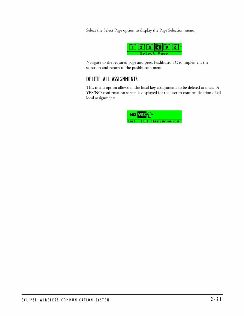
Select the Select Page option to display the Page Selection menu.
Navigate to the required page and press Pushbutton C to implement the selection and return to the pushbutton menu.
DELETE ALL ASSIGNMENTSThis menu option allows all the local key assignments to be deleted at once. A YES/NO confirmation screen is displayed for the user to confirm deletion of all local assignments.
E C L I P S E W I R E L E S S C O M M U N I C A T I O N S Y S T E M 2 - 2 1

E C L I P S E W I R E L E S S C O M M U N I C A T I O N S Y S T E M2 - 2 2

OPERATING THE ECLIPSE TRANSCEIVER/ANTENNA
TRANSCEIVER/ANTENNAThe Eclipse transceiver/antennas form the transmission link between the Eclipse beltpacks and the Eclipse base. Multiple units are used to support the beltpacks and to create larger, customized coverage areas. Each transceiver/antenna is connected to the Eclipse base, either directly or via a splitter. The unit has two flanges on the rear side that permit the unit to be screwed or otherwise attached to surfaces.
Figure 3-1: Eclipse Transceiver/Antenna
TRANSCEIVER/ANTENNA TOP PANEL
Omnidirectional AntennasA pair of omnidirectional antennas are provided with the transceiver/antenna.
Antennas with different coverage patterns (directional units) that are appropriate for the 1.9 GHz range may be substituted for the provided antennas, if variations in coverage pattern are required.
3
E
C L I P S E W I R E L E S S C O M M U N I C A T I O N S Y S T E M 3 - 1
TRANSCEIVER ANTENNA BOTTOM/CONTROL PANEL
Figure 3-2: Eclipse Transceiver/Antenna Bottom/Control Panel
Serial Data Connector
This 3 mm (1/8 inch) tip-ring-sleeve (TRS) connector is used for upgrading the firmware in the transceiver/antenna. It will typically be unused.
Data Signal LED
This yellow LED indicates that a connection has been established between the Eclipse base and the transceiver/antenna, and that it is actively creating a coverage zone within which the beltpacks can operate. If it is off, check the cable connections at both ends, as well as the powering.
Matrix Connector
This RJ-45 connector is used to connect the bi-directional signal from the Eclipse base, directly or via the splitter. Up to 1,000 meters of 4-pair 24 AWG CAT-5 cable can be used for this connection between base and transceiver/antenna. If 26 AWG CAT5 cable is used the maximum distance is 500 meters.
Power LED
This green LED indicates that the transceiver/antenna is receiving power, either from its local power supply or from the connected CAT-5 cable (distances up to 300 meters, or 925 feet, from the base or the splitter) being powered via the Eclipse base.
DC In Power Connector
This connector is used to locally power the transceiver/antenna with the supplied universal power supply. Use of local power is required when the transceiver/antenna is located more than 300 meters (925 feet) from the Eclipse base or the splitter, and is recommended even when the transceiver/antenna is closer whenever it is available and convenient.
1 2 3 4 5
1 Serial Data Connector2 Data Signal Light 3 Matrix Connector
4 Power Indicator Light5 DC IN Power Connector
1
2
3
4
5
E C L I P S E W I R E L E S S C O M M U N I C A T I O N S Y S T E M 3 - 2

CABLING THE TRANSCEIVER/ANTENNASEach Eclipse transceiver/antenna receives its necessary data and digital communications audio via a direct connection with the matrix E-Que ports. Between these two ports, up to 10 transceiver/antennas can be supported. A transceiver/antenna may either be directly connected to an E-Que port using 4-pair CAT-5 data cable with RJ-45 connectors on each end, or it may be connected to the base through an antenna splitter.
BELTPACK SUPPORT CAPACITIES FOR TRANSCEIVER/ANTENNASEach transceiver/antenna can support five beltpacks within one coverage zone. With the supplied omnidirectional antennas, the coverage pattern is circular or donut-shaped, with a maximum range of up to 250 meters (800 feet), but with typical range between 50 meters and 150 meters – depending on the environment in which it is installed.
When designing the system, determine how many beltpack users will be in or passing through a given coverage zone. If it will be five or fewer users, then place one transceiver/antenna in the center of that area. If it is between 6 and 10 users, place two transceiver/antennas next to each other, both with a direct connection to the Eclipse base or splitter. In larger systems – approaching 20 beltpacks – it is wiser to allow one transceiver/antenna for every 3 to 4 users to ensure smooth handoffs between transceiver/antennas. It is good practice to have each beltpack “seeing” two or more antennas, so a minimum of two antennas in any system is to be considered.
If a sixth beltpack user goes into a coverage zone with only one transceiver/antenna, and that user is out of range from another transceiver/antenna in the overall system to which that beltpack is currently connected, it will lose connection with the system. This is because the tranceiver/antenna has a maximum capacity of five beltpacks at a time. If one of the existing users in that coverage area turns off a beltpack or leaves the area, then the sixth beltpack will find an open slot and will be reconnected with the system.
The proprietary technology within Eclipse permits the beltpack user to go between coverage zones created by different transceiver/antennas connected to the Eclipse base, and for the system to hand over the communication between beltpack and base from one transceiver/antenna to the next one. Thus, a larger, customizable communications area may be designed.
COVERAGE AREAS UNDER VARIOUS CONDITIONSJust as with any other product communicating via radio waves, the effective distance between the beltpack and the transceiver/antenna (the range) will differ depending on the particular environment in which it is being used. Radio waves can be attenuated by walls, floors, ceilings, trees, shrubbery, the human body (such as an audience), and numerous other objects. They can be reflected and/or stopped by metallic objects such as structural beams, safety doors, lighting equipment and truss, bodies of water, and so on.
E C L I P S E W I R E L E S S C O M M U N I C A T I O N S Y S T E M 3 - 3

Under ideal conditions, the maximum range between a Eclipse beltpack and a transceiver/antenna is 250 meters (about 800 feet). Typical distances are between approximately 50 meters (about 160 feet) and 150 meters (about 485 feet), depending on the particular environment.
As the transceiver/antenna requirements for a particular installation are being determined, keep in mind both the number of beltpack users who will be working in a particular area (based on the five-beltpack capacity of each transceiver/antenna), and the layout and potential RF attenuating and reflecting items in the location. Be conservative in your distance estimates to make sure that you include enough transceiver/antennas to provide the necessary coverage for the installation. Also note that additional transceiver/antennas may be added to a base, up to a maximum of 10.
TRANSCEIVER/ANTENNA SETUP RULES AND TIPSKeep the following general rules and tips in mind:
• Keep antennas high (typically, though lower placements away from interfering objects can at times be beneficial) and line-of-sight.
• Keep them away from larger metallic objects and surfaces, and from lighting truss.
• With the provided omnidirectional antennas, the coverage is circular so put the transceiver/antennas in the center of the area in which you want coverage.
• In outdoor settings with line-of-sight, the absence of beneficial reflections of the radio waves may lead to shorter than expected range; directional antennas may be of benefit here.
• When overlapping the coverage zones of transceiver/antennas to create larger continuous coverage areas, test the in-between areas with a beltpack for potential areas of low RF signal; adjust the positioning of the antennas as needed.
• Because of potential body shielding as the user moves, it will be useful to place two transceiver/antennas in different locations within larger working areas to minimize low-level signals and potential signal dropouts.
• Going between a larger area and a corridor via a door, especially a heavy or shielded one, or where the walls are thick, place a second antenna in the corridor near the doorway to assure continuous coverage.
TRANSCEIVER/ANTENNA SPLITTERThe antenna splitter is the device that connects multiple transceiver/antennas to the Eclipse matrix. It has an RJ-45 connector that carries the data between a base transceiver port and the splitter, and five RJ-45 connectors to feed that information to and from up to five antennas. The splitter is always locally powered via the supplied external in-line universal power supply.
E C L I P S E W I R E L E S S C O M M U N I C A T I O N S Y S T E M 3 - 4

SPLITTER FRONT CONNECTOR PANEL
Figure 3-3: Eclipse Splitter Front Connector Panel
Base Connection Indicator Light
This yellow light indicates that the splitter is receiving data from the Eclipse base.
Matrix (Eclipse Base) Connector
This RJ-45 connector accepts a 4-pair data cable from the Eclipse matrix E-Que port. This cable can be up to 1,000 meters in length if 24 AWG cable is used or up to 500 meters if 26 AWG cable is used.
Splitter-to-Transceiver/Antenna Signal Indicator Light
These yellow lights indicate that a connection from the Eclipse base is available to the particular transceiver connected to that port.
Transceiver/Antenna Connectors
These five RJ-45 connectors are used to connect up to five remote transceiver/antennas to the splitter, and via the splitter to the Eclipse matrix. Each of these cables can be up to 1,000 meters in length if 24 AWG cable is used or up to 500 meters long if 26 AWG cable is used.
1 2 3 4
1 Base Connection Indicator Light2 Matrix Connector 3 Splitter-to-Transceiver/Signal Indicator Lights (5)4 Transceiver/Antenna Connectors (5)
1
2
3
4
E C L I P S E W I R E L E S S C O M M U N I C A T I O N S Y S T E M 3 - 5

SPLITTER REAR PANEL
Serial Data Connector
This 3.5 mm (1/8 inch) tip-ring-sleeve (TRS) connector is used for upgrading the firmware in the splitter. It will typically be unused.
Power Indicator
This green LED indicates that the splitter is receiving power from the external power supply.
DC IN Power Connector
This connector is used to locally power the antenna splitter with the supplied universal power supply. Use of local power is required.
EXP IN Connector
This male DB-15 connector is reserved for future use.
EXP OUT Connector
This female DB-15 connector is reserved for future use.
CONNECTING AN ANTENNA SPLITTER TO THE ECLIPSE BASE AND TO TRANSCEIVER/ANTENNASAfter the connections have been made between the splitter and the transceiver/antennas, make sure that the data LED’s are lit at the individual ports on the antenna splitter. Also make sure that the both the green power LED and the yellow data LED are lit on each transceiver/antenna. If all are properly lit, then the connection has been successfully made and the coverage zones will be active and will support beltpacks. If the transceiver antennas are not lit, check the connections.
1 2 3 4 5
1 Serial Data Connector 2 Power Indicator Light 3 DC IN Power Connector
4 Reserved for future use 5 Reserved for future use
1
2
3
4
5
E C L I P S E W I R E L E S S C O M M U N I C A T I O N S Y S T E M 3 - 6

INSTALLING A SYSTEM
You can begin using a Eclipse system as soon as you receive it, as long as the beltpacks are registered to the base, using the generic user labels for the beltpacks and the rear-panel connections.
PLACING THE MATRIX The first stage in setup is placing the matrix in a convenient location, knowing that it is the central routing unit of the Eclipse system.
At this stage, if they are unregistered, you may want to register all of the beltpacks with the Eclipse Configuration System (ECS), or at least register one or two for system setup and testing. Follow the instructions in the Eclipse Configuration System instruction manual to register the beltpacks.
PLACING THE ANTENNAS AND SPLITTERS The next step is to begin placing antennas and splitters to provide the necessary coverage areas for all of the beltpacks. Your first placements of antennas and splitters will be experimental and temporary. After placing the antennas, you will walk through the coverage areas to check for gaps and then re-locate the antennas accordingly.
More information on checking coverage areas is given later in this chapter, in the sections “Determining Coverage Areas” and “Doing a Site Survey to Determine Coverage Areas.”
The following questions will help you to begin placing the antennas:
• What areas will have more than five active beltpack users in them at any time? Co-locate a second transceiver/antenna there.
• Is there a central place to locate an antenna so that it will provide omnidirectional (all directions / circular) coverage?
• Are there balcony areas, corridors, or other rooms or areas that will require coverage with antennas?
Next decide where the antenna splitter(s) that feed these antennas will be safely located. For systems with only one or two transceiver/antennas, the cable runs will go directly from the transceiver ports on the base E-Que card.
WIRING THE ANTENNAS AND SPLITTERSTo wire antennas and splitters:
1. Run 4-pair CAT-5 cable from the Eclipse base to the antenna or splitter, and determine that the antenna or splitter is showing both power (green LED lit) and signal (yellow LED lit when the matrix is on).
An Eclipse wireless system
can work immediately when
you receive it, as long as the
beltpacks are registered to
the system.
4
E
C L I P S E W I R E L E S S C O M M U N I C A T I O N S Y S T E M 4 - 1
Note: To meet FCC emissions requirements, you must fit a ferrite on any CAT-5 cable plugged into either of the two ports labeled “tranceivers.” The ferrite should be fitted at the E-Que card end of the CAT-5 cable. Position the ferrite as close to the E-Que card as possible. The manufacturer of the ferrite is Wurth Elektronix. The part number is 742 711 32.
2. Run 4-pair CAT-5 cable from the splitter to each of the transceiver/antennas. 3. Make sure that the local power supplies are plugged into the antennas, unless
they are close enough to the matrix to draw power from the attached CAT-5 cable.
You will know that a transceiver/antenna has sufficient power from the cable if the green power LED and the yellow data LED light up. If you have several longer runs and are attempting to power the transceiver/antennas from the base / splitter connection, check each one again when the are all connected. The local powering for the transceiver/antenna is recommended in most cases to provide the most reliable long-term Eclipse installation.
Note that 4-pair CAT-5 cable with RJ-45 connectors on each end is specified for connection between the E-Que card and the transceiver/antennas. Use of other cable can result in markedly shorter distances of cable runs and other possibly other performance problems.
During the initial system setup, before walking through the system with a beltpack to check for gaps in coverage, it is wise to avoid “permanently” installing the transceiver/antennas. Hold them in place in some temporary way until their optimal position is determined.
DETERMINING COVERAGE AREASAfter you have initially set up the transceiver/antennas and splitters, you can proceed to test the coverage areas and re-locate antennas and splitters, if necessary, for optimal coverage.
To determine coverage areas:
1. Once the base, splitter(s), and transceiver/antennas have been placed and wired, turn on a beltpack (assuming that it has been registered with ECS) and walk the coverage area – ideally speaking with someone else via the on-base headset or a party-line or matrix connection with the base.Alternatively, use the “site survey” mode on the beltpack (see “Doing a Site Survey to Determine Coverage Areas” below). It is often best to begin with one antenna in place, and then place additional units to enhance coverage.
2. Walk through all of the areas where beltpack users will typically be moving, and note any areas of weak signal, dropout, or disconnection from the system. Pay special attention to the overlap areas between antenna coverage zones, making sure sufficient signal strength is there from each of the transceiver/antennas to make a clean handoff between them for the beltpack.
3. Finally, when the coverage zones have been properly and effectively set up, it is time to program the system. See the ECS Instruction manual for setting up a system.
Note: To meet FCC emissions requirements, you must fit a ferrite on any CAT-5 cable plugged into either of the two ports labeled “tranceivers.” The ferrite should be fitted at the E-Que card end of the CAT-5 cable. Position the ferrite as close to the E-Que card as possible. The manufacturer of the ferrite is Wurth Elektronix. The part number is 742 711 32.
E C L I P S E W I R E L E S S C O M M U N I C A T I O N S Y S T E M4 - 2

DOING A SITE SURVEY TO DETERMINE COVERAGE AREAS Some Eclipse users may want to test coverage areas more extensively before setting up a a complete system. Testing a system in the setting in which it will be located helps you to set up the system successfully to meet your needs. Factors in the local setting may affect the areas a system can cover, so it is important to plan a site setup accordingly.
Doing a complete site survey, as described below, helps you to set up an optimal system.
TESTING COVERAGE AREAS OF INDIVIDUAL ANTENNAS1. Place the Eclipse matrix in a convenient location. Register one beltpack to the
matrix.
2. Place one antenna in the center of the coverage area.
3. Put the beltpack into “site survey mode” by first pressing the power button on the back of the beltpack, and then simultaneously pressing the two front-panel scroll buttons.
• When you do this, the beltpack’s display shows the “site survey” screen. Figure 4-1 shows a beltpack’s site survey screen.
4. Walk around the antenna with the beltpack, monitoring the beltpack’s signal strength and error rate at various distances.
The signal strength is shown in the Received Signal Strength Indication (RSSI) field in the leftmost lower corner of the beltpack’s display. The error rate is shown in the ERR field in the middle of the display.
Figure 4-1: A Beltpack’s Site Survey Screen
Received Signal Strength Indication, ranges from 0 to 55. Best beltpack performance is at30 or above.
Error rate should not exceed a few percent.
RPN field shows the antennathat the beltpack is connected to.
RFPI: EIC RPN 10
0-0000-000-00-00Carr: 0 Slot: 2RSS!: 30 Errs: 0.1%
E C L I P S E W I R E L E S S C O M M U N I C A T I O N S Y S T E M 4 - 3

• The RSSI (signal strength) number will fluctuate, ranging from 0 to 55, as you walk through the coverage area, and may even fluctuate as you stand still. As a rule-of-thumb, you will obtain best system performance when the signal strength remains at 30 or above. If the signal strength falls below 30, you may start losing audio. This is the limit of the coverage zone.
• The ERR (error rate) number indicates packets of audio which are lost or corrupted. When this number exceeds a few percent you may start hearing audible audio breakup.
A beltpack can transmit to an antenna outdoors at an average distance of 125 meters when the beltpack has an unobstructed “line-of-sight” path to the antenna. In ideal conditions, the range may be as high as 250 meters. Indoors, a beltpack can transmit to an antenna at an average distance of 50 meters.
5. Draw a map of the coverage zone for the antenna. The coverage zone is the area where the signal strength, as a rule-of-thumb, is 30 or above and the error rate is below a few percent.
6. Repeat this process, one antenna at a time, for as many antennas as necessary to cover the required area. Overlap coverage zones so that there is no area where the signal strength is below 30, and no area where the error rate is above a few percent.
7. You will need to adjust antenna placement to get the best coverage.
Figure 4-2: Mapping overlapping coverage zones
In some environments you may observe that despite having a high signal strength, the beltpack consistently reports a high error rate.
This could be due to two things:
• In-band interference from an RF source broadcasting in the DECT area of the spectrum. This can be verified using a DECT band monitor (which can be purchased from Vitec Group Communications), or by using a Spectrum Analyser.
• Long Delay Spread Multipath, where the signal is bounced off a number of reflective surfaces, such as metal ceilings, gantries, walkways or other large structures. This problem is greatest where the reflective surface is large and exists at a range of distances from the antenna. To resolve this problem, consider siting the antenna where it cannot “see” the reflective surface, installing a reflector close to the antenna between it and the reflective surface, or purchasing directional antennas. Contact VGC customer support for more information.
Zone A Zone B
Zone C 1 User
5 Users 4 Users
E C L I P S E W I R E L E S S C O M M U N I C A T I O N S Y S T E M4 - 4

TESTING ANTENNA HANDOFF After you test the coverage areas for individual antennas, test the handoff between the antennas. When you walk through a coverage area with the beltpack, the beltpack searches to find the antenna with the best signal strength, and switches transmission to that antenna. Therefore the beltpack continually hands off transmission among antennas as you move through the coverage area.
To test antenna handoff, connect any additional antennas in the installation and walk through the coverage areas to ensure that the coverage is continuous and complete, without audio breakups. You can tell which antenna the beltpack transmits to by looking at the RPN number in the top rightmost corner of the beltpack’s display when the beltpack is in “site survey” mode. Reposition antennas if necessary. Note that the numbering to identify antennas starts at “6” to identify the first antenna, as shown in the table below.
Table 4-1: How antennas are numbered
ASSIGNING BELTPACKS TO COVERAGE AREASEach antenna is designed to handle five beltpacks simultaneously. Although it can achieve this in good conditions, this may not always be possible for a number of reasons. First, interference or propagation problems may mean that not all antenna slots are available all the time. Second, a beltpack constantly searches for the best antenna signal, and may frequently switch antennas. To make this transmission seamless, a beltpack maintains the connection to its current antenna until it is confident that the new antenna is functioning well. Therefore, for a short period of time during this transition, a single beltpack can occupy slots on more than one antenna.
This means that for zones in which you are likely to need coverage for five or more beltpacks simultaneously, it is recommended that you install a second antenna. Similarly, for good coverage for nine or more beltpacks simultaneously, a third antenna may be required.
BELTPACK SCREEN DISPLAYS: WHICH SIGNIFIES: RPN 6 Antenna 1 on transceiver port 1 RPN 7 Antenna 2 on transceiver port 1 RPN 8 Antenna 3 on transceiver port 1RPN 9 Antenna 4 on transceiver port 1RPN 10 Antenna 5 on transceiver port 1RPN 11 Antenna 1 on transceiver port 2RPN 12 Antenna 2 on transceiver port 2RPN 13 Antenna 3 on transceiver port 2RPN 14 Antenna 4 on transceiver port 2RPN 15 Antenna 5 on transceiver port 2
E C L I P S E W I R E L E S S C O M M U N I C A T I O N S Y S T E M 4 - 5

CONDITIONS AFFECTING COVERAGE AREASThe environment in which a system is located affects the coverage area for any particular beltpack/antenna combination. The presence of walls, floors, ceilings, trees, shrubbery, people, and numerous other items may affect the coverage zone. Metallic objects, safety doors, lighting equipment, and bodies of water may possibly block transmission. You must take these factors into consideration when planning your installation.
E C L I P S E W I R E L E S S C O M M U N I C A T I O N S Y S T E M4 - 6

SPECIFICATIONS
Eclipse Beltpack
Beltpack Frequency Response 100 Hz – 7.1 kHz
Beltpack Assignment-Select Buttons 3, used to scroll and select talk/listen “pages”and also to edit beltpack menu options
“Label” Assignments per Select Button 2 (two simultaneous talk/listen paths orchannels)
Number of Full-Duplex Audio Paths 6 (3 pairs), with individual level control
Level/Talk Controls 2 top-mounted push-to-talk rotary encoders
Headset Connector 4-pin male, Clear-Com standard
Microphone Type Dynamic or electret, selectable in beltpackmenu
Microphone and Headset Limiters Selectable in beltpack menu
Powering Alkaline Battery, 4 AA alkaline cellsRechargeable, 4 NiMH cells in AA format
Battery Charging In unit, via supplied external power supplyconnected to beltpack
Battery Life Approximately 8 hours with 4 fresh AAalkaline batteries or 4 AA high-amperageNiMH cells
Range from Single Transceiver/Antenna 125 m from transceiver/antenna in
line-of-sight conditions; 50 m indoors; usemultiple transceiver/antennas for larger, custom coverage areas
Dimensions Tapered design, at largest points approx. 38 x 87 x 144 mm (dwh) (1.5 x 3.5 x 5.75 inches)
Weight (with batteries) Approx. 13 oz.
5
E
C L I P S E W I R E L E S S C O M M U N I C A T I O N S Y S T E M 5 - 1
Transceiver/Antenna
Beltpacks Supported Per Transceiver/Antenna 5, in one cellular zone
Transceiver Antenna Transmission Range Up to 250 m (800 ft.), line of sight
Maximum Distance, Base to Transceiver Via Base Port 1,000 m (3,200 ft.) using 24 AWG cable
500 m (1,600 ft) using 26 AWG cable
Maximum Distance, Transceiver Powered By Base Port 300 m (975 ft.)
Local Powering Via 24VDC power supply
Range per Transceiver/Antenna 150 m from transceiver/antennaideal, line-of-sight conditions; 50 m indoors;use multiple transceiver/antennas for larger, custom coverage areas
Connection to Eclipse Base RJ-45
Mounting Via integral tabs with holes for screws
Dimensions 38 x 125 x 153 mm (dwh)(1.5 x 5.0 x 6.1 inches)
Weight Approx. 9 oz.
Transceiver/Antenna Splitter
Number of Transceiver/Antennas Supported 10; Note: In the USA, until FCC opens the
allowed bandwidth, any one area can only have 5 antennas.
Number of Splitters Per Base 2
Connection Between Base and Splitter 4-pair CAT5 cable with RJ-45
Connection Between Splitter and Transceiver/Antennas 4-pair CAT5 cable with RJ-45
Powering of Splitter Locally powered via external power supply
E C L I P S E W I R E L E S S C O M M U N I C A T I O N S Y S T E M 5 - 2

Transmission Method
Method of RF Operation DECT standard, using two DECT bands perbeltpack for wider frequency response
Modulation QPSK
Frequencies of Operation 1.92 – 1.93 GHz
RF Output 250 mW burst, average level 2 - 4 mW
Theory of OperationDynamic allocation of frequencies and handoff of beltpacks among the transceiver/antennas up to their individual limit of 5 connected beltpacks at a time; each beltpack is assigned a “virtual port” within the Eclipse base.
E C L I P S E W I R E L E S S C O M M U N I C A T I O N S Y S T E M 5 - 3

E C L I P S E W I R E L E S S C O M M U N I C A T I O N S Y S T E M 5 - 4

APPENDIX 1: DECT CARRIER FREQUENCY CHART
Table 6-1: DECT Carrier Frequency Chart
* Carriers 23 through 27 are those used in the USA.
RFC CARRIER FREQUENCY RFC CARRIER FREQUENCY
0 1897.344 17 1911.168
1 1895.616 18 1912.896
2 1893.888 19 1914.624
3 1892.160 20 1916.352
4 1890.432 21 1918.080
5 1888.704 22 1919.808
6 1886.976 23* 1921.536
7 1885.248 24* 1923.264
8 1883.520 25* 1924.992
9 1881.972 26* 1926.720
10 1899.072 27* 1928.448
11 1900.800 28 1930.176
12 1902.528 29 1931.904
13 1904.256 30 1933.632
14 1905.984 31
15 1907.712 32
16 1909.440
E
C L I P S E W I R E L E S S C O M M U N I C A T I O N S Y S T E M 6 - 1
E C L I P S E W I R E L E S S C O M M U N I C A T I O N S Y S T E M 6 - 2

LIMITED WARRANTY
Vitec Group Communications (VGC) warrants that at the time of purchase, the equipment supplied complies with any specification in the order confirmation when used under normal conditions, and is free from defects in workmanship and materials during the warranty period.
During the warranty period VGC, or any service company authorized by VGC, will in a commercially reasonable time remedy defects in materials, design, and workmanship free of charge by repairing, or should VGC in its discretion deem it necessary, replacing the product in accordance with this limited warranty. In no event will VGC be responsible for incidental, consequential, or special loss or damage, however caused.
WARRANTY PERIODThe product may consist of several parts, each covered by a different warranty period. The warranty periods are:
• Cables, accessories, components, and consumable items have a limited warranty of 90 days.
• Headsets, handsets, microphones, and spare parts have a limited warranty of one year.
• UHF wireless IFB products have a limited warranty of one year.
• UHF wireless intercom systems have a limited warranty of three years.
• All other Clear-Com and Drake brand systems and products, including beltpacks, have a limited warranty of two years.
The warranty starts at the time of the product’s original purchase. The warranty start date for contracts which include installation and commissioning will commence from the earlier of date of the Site Acceptance Test or three months from purchase.
TECHNICAL SUPPORT To ensure complete and timely support to its customers, VGC’s User Support Center is staffed by qualified technical personnel. Telephone and email technical support is offered worldwide by the User Support Center.
The User Support Center is available to VGC’s customers during the full course of their warranty period.
Instructions for reaching VGC’s User Support Centers are given below.
Telephone for Europe, Middle East and Africa: +49 40 6688 4040 or +44 1223 815000
Return Material
Authorization (RMA)
numbers are required for all
returns.
Both warranty and
non-warranty repairs are
available.
W
A R R A N T Y i
Telephone for the Americas and Asia: +1 510 337 6600
Email: [email protected]
Once the standard warranty period has expired, the User Support Center will continue to provide telephone support if you have purchased an Extended Warranty.
For latest contact information please refer to the Service and Support section at www.clearcom.com.
WARRANTY REPAIRS AND RETURNS Before returning equipment for repair, contact a User Support Center to obtain a Return Material Authorization (RMA). VGC representatives will give you instructions and addresses for returning your equipment. You must ship the equipment at your expense, and the support center will return the equipment at VGC’s expense.
For out-of-box failures, use the following contact information:
Europe, Middle East and Africa
Tel: +44 1223 815000 Email: [email protected]
North America, Canada, Mexico, Caribbean & US Military
Tel: +1 510 337 6600 Email: [email protected]
Asia Pacific & South America
Tel: +1 510 337 6600 Email: [email protected]
VGC has the right to inspect the equipment and/or installation or relevant packaging.
For latest contact information please refer to the Service and Support section at www.clearcom.com.
NON-WARRANTY REPAIRS AND RETURNSFor items not under warranty, you must obtain an RMA by contacting the User Support Center. VGC representatives will give you instructions and addresses for returning your equipment.
You must pay all charges to have the equipment shipped to the support center and returned to you, in addition to the costs of the repair.
EXTENDED WARRANTYYou can purchase an extended warranty at the time of purchase or at any time during the first two years of ownership of the product. The purchase of an extended warranty extends to five years the warranty of any product offered with a standard two-year warranty. The total warranty period will not extend beyond five years.
i
W A R R A N T Yi
Note: VGC does not offer warranty extensions on UHF wireless intercom systems, or on any product with a 1-year or 90-day warranty.
LIABILITY THE FOREGOING WARRANTY IS VGC'S SOLE AND EXCLUSIVE WARRANTY. THE IMPLIED WARRANTY OF MERCHANTABILITY AND FITNESS FOR A PARTICULAR PURPOSE AND ANY OTHER REQUIRED IMPLIED WARRANTY SHALL EXPIRE AT THE END OF THE WARRANTY PERIOD. THERE ARE NO OTHER WARRANTIES (INCLUDING WITHOUT LIMITATION WARRANTIES FOR CONSUMABLES AND OTHER SUPPLIES) OF ANY NATURE WHATSOEVER, WHETHER ARISING IN CONTRACT, TORT, NEGLIGENCE OF ANY DEGREE, STRICT LIABILITY OR OTHERWISE, WITH RESPECT TO THE PRODUCTS OR ANY PART THEREOF DELIVERED HEREUNDER, OR FOR ANY DAMAGES AND/OR LOSSES (INCLUDING LOSS OF USE, REVENUE, AND/OR PROFITS). SOME STATES DO NOT ALLOW THE EXCLUSION OR LIMITATION OF INCIDENTAL OR CONSEQUENTIAL DAMAGES OR THE LIMITATION ON HOW LONG AN IMPLIED WARRANTY LASTS, SO THE ABOVE LIMITATIONS MAY NOT APPLY TO YOU. IN ANY EVENT, TO THE MAXIMUM EXTENT PERMITTED UNDER APPLICABLE LAW, VGC'S LIABILITY TO CUSTOMER HEREUNDER SHALL NOT UNDER ANY CIRCUMSTANCES EXCEED THE COST OF REPAIRING OR REPLACING ANY PART(S) FOUND TO BE DEFECTIVE WITHIN THE WARRANTY PERIOD AS AFORESAID.
This warranty does not cover any damage to a product resulting from cause other than part defect and malfunction. The VGC warranty does not cover any defect, malfunction, or failure caused beyond the control of VGC, including unreasonable or negligent operation, abuse, accident, failure to follow instructions in the manual, defective or improperly associated equipment, attempts at modification and repair not approved by VGC, and shipping damage. Products with their serial numbers removed or defaced are not covered by this warranty.
This warranty does not include defects arising from installation (when not performed by VGC), lightning, power outages and fluctuations, air conditioning failure, improper integration with non-approved components, defects or failures of customer furnished components resulting in damage to VGC provided product.
This limited warranty is not transferable and cannot be enforced by anyone other than the original consumer purchaser.
This warranty gives you specific legal rights and you may have other rights which vary from country to country.
W
A R R A N T Y i i i
i
W A R R A N T Yv