TEGAM Inc. Model 2732 50 MHz x 2 Channels …...Model 2732: Two Channel 50 MHz Function/Arbitrary...
189
Model 2732: Two Channel 50 MHz Function/Arbitrary Waveform Generator a TEGAM Inc. Model 2732 50 MHz x 2 Channels Function/Arbitrary Waveform Generator Instruction Manual PN# 2732-901-01CD Publication Date: July 2007 REV. D © Copyright 2007, TEGAM, Inc. All rights reserved. NOTE: This user’s manual was as current as possible when this product was manufactured. However, products are constantly being updated and improved. Because of this, some differences may occur between the descriptions in this manual and the product received.
Transcript of TEGAM Inc. Model 2732 50 MHz x 2 Channels …...Model 2732: Two Channel 50 MHz Function/Arbitrary...
Model 2732: Two Channel 50 MHz Function/Arbitrary Waveform Generator a
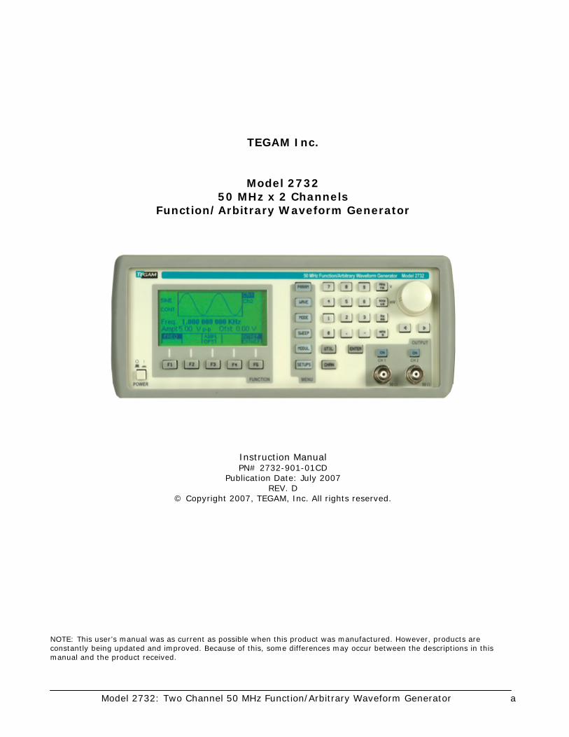
TEGAM Inc.
Model 2732 50 MHz x 2 Channels
Function/Arbitrary Waveform Generator
Instruction Manual PN# 2732-901-01CD
Publication Date: July 2007 REV. D
© Copyright 2007, TEGAM, Inc. All rights reserved.
NOTE: This user’s manual was as current as possible when this product was manufactured. However, products are constantly being updated and improved. Because of this, some differences may occur between the descriptions in this manual and the product received.
Model 2732: Two Channel 50 MHz Function/Arbitrary Waveform Generator b
Table of Contents
I INSTRUMENT DESCRIPTION............................................................................1-1 Instrument Description ........................................................................... 1-3 Feature Overview ………............................................................................ 1-4 Model 2732 Accessories .......................................................................... 1-5 Performance Specifications ...................................................................... 1-6 Frequency Characteristics .............................................................. 1-6 Arbitrary Characteristics ................................................................ 1-6 Output Characteristics................................................................... 1-6 Waveform Characteristics .............................................................. 1-7 Operating Modes .......................................................................... 1-7 Modulation Characteristics ............................................................. 1-7 Sweep Characteristics ................................................................... 1-8 Variable Phase ............................................................................. 1-8 Inputs and Outputs....................................................................... 1-8 Computer Interfaces ..................................................................... 1-8 General Specifications................................................................... 1-9 II PREPARATION FOR USE ..................................................................................2-1 Unpacking and Inspection........................................................................ 2-3 Safety Information and Precautions .......................................................... 2-3 Servicing Safety Summary ...................................................................... 2-5 Line Voltage and Fuse Selection ............................................................... 2-6 III QUICK START INSTRUCTIONS.........................................................................3-1 Introduction .......................................................................................... 3-3 Power the Unit ....................................................................................... 3-3 Your First Waveform............................................................................... 3-3 Instrument Settings................................................................................ 3-4 Table 3.1 – Factory Default Settings................................................ 3-4 Using the Function Generator................................................................... 3-5 Downloading a Waveform from WaveWorks DDS to the 2732 ....................... 3-7 Using WaveWorks DDS to Create an Arbitrary Waveform ............................. 3-8 General Tips for Usage............................................................................ 3-9 IV OPERATING INSTRUCTIONS............................................................................4-1 General Description ................................................................................ 4-3 Front Panel............................................................................................ 4-3 Figure 4.1 – Model 2732 Front Panel ............................................... 4-3 Display Window............................................................................ 4-4 Front Panel Controls ..................................................................... 4-4 Front Panel Output Connectors ....................................................... 4-4 Rear Panel ............................................................................................ 4-5 Figure 4.2 – Model 2732 Rear Panel ................................................ 4-5 Rear Panel Input Connectors.......................................................... 4-6 Rear Panel Output Connectors........................................................ 4-6
Model 2732: Two Channel 50 MHz Function/Arbitrary Waveform Generator c
Table of Contents
IV OPERATING INSTRUCTIONS CONT’D............................................................... MENU Keys ........................................................................................... 4-7 [PARAM] Parameter Menu.............................................................. 4-7 Figure 4.3 – Parameter Menu Tree ........................................ 4-7 Frequency/Rate.................................................................. 4-7 Amplitude.......................................................................... 4-8 Table 4.1 –Waveform Amplitudes (Examples) ......................... 4-8 Offset ............................................................................... 4-9 Table 4.2 – Voltage Offset Ranges ........................................ 4-9 Amplitude Units.................................................................. 4-10 Internal/External Reference ................................................. 4-10 [WAVE] Wave Menu...................................................................... 4-11 Figure 4.4 – Wave Menu Tree............................................... 4-11 Pulse ................................................................................ 4-12 Figure 4.5 – Definition of 10-90% Lead and Trail..................... 4-13 Figure 4.6 – Definition of Width, Leading and Trailing Edges ..... 4-13 Figure 4.7 – Definition of Period & Width................................ 4-13 Arbitrary Waveform Menu.................................................... 4-15 Table 4.3 –Length Limits for Predefined Waveforms................. 4-20 [MODE] Trigger Mode Menu ........................................................... 4-24 Figure 4.8 – Trigger Mode Menu Tree .................................... 4-24 [SWEEP] Sweep Menu................................................................... 4-27 Figure 4.9 – Sweep Menu Tree ............................................. 4-27 [MODUL] Modulation Menu ........................................................... 4-29 Figure 4.10 - Modulation Menu Tree ...................................... 4-29 [SETUPS] Setups Menu ................................................................. 4-33 Figure 4.11 – Setups Menu Tree ........................................... 4-33 Front Panel Keys .................................................................................... 4-35 [UTIL] Utility Menu ....................................................................... 4-35 Figure 4.12 – Utility Menu Tree............................................. 4-35 [ON] ON Key ............................................................................... 4-37 [◄][►] Cursor Movement Keys........................................................ 4-37 Rotary Input Knob........................................................................ 4-37 Power On Settings........................................................................ 4-37 [ENTER] Enter Key ....................................................................... 4-37 UNITS Keys ................................................................................. 4-37 Power-On Settings........................................................................ 4-38 Table 4.4 – Power On Default Settings (Location 0) ........................... 4-38 Instrument Operation ............................................................................. 4-39 Impedance Matching..................................................................... 4-39 Waveform and Execution Memory................................................... 4-40 Displaying Errors.......................................................................... 4-41 Table 4.5 – Error Messages for the 2732.......................................... 4-41 Using the Model 2732 ................................................................... 4-42 Generating a Standard Waveform ................................................... 4-43 Defining a Pulse Waveform ............................................................ 4-44 Creating an Arbitrary Waveform ..................................................... 4-45 Example Text File ......................................................................... 4-45
Model 2732: Two Channel 50 MHz Function/Arbitrary Waveform Generator d
Table of Contents
IV OPERATING INSTRUCTIONS CONT’D...............................................................
Creating an Arbitrary Waveform: Loading Individual Data Points ......... 4-46 Defining a Wave Segment for Execution .......................................... 4-47 Creating a Complex Arbitrary Waveform .......................................... 4-48 Figure 4.13 – Sine Wave with Superimposed Noise and Glitches.......... 4-51 Setting the Frequency................................................................... 4-52 Generating a Waveform Output ...................................................... 4-53 Modifying a Waveform’s Output ...................................................... 4-53 Using Voltage Offset ..................................................................... 4-53 Storing and Recalling a Waveform Generator Setup........................... 4-54 Generating and Transferring Data from WaveWorks DDS to Model 2732 .............................................. 4-55 V PROGRAMMING AND INTERFACING ................................................................5-1 BNC Input and Output Connections........................................................... 5-3 Front Panel Output Connectors ....................................................... 5-3 Rear Panel Input Connectors.......................................................... 5-4 Rear Panel Output Connectors........................................................ 5-5 RS-232C Programming............................................................................ 5-6 General....................................................................................... 5-6 Figure 5.1 – Cable End View .......................................................... 5-6 Table 5.1 – Pin Designations for RS-232C Cable................................ 5-6 RS-232C Operation....................................................................... 5-7 GPIB Interface ....................................................................................... 5-8 Overview .................................................................................... 5-8 Figure 5.2 – GPIB Connector Pin Assignments .................................. 5-8 Device State................................................................................ 5-9 Interface Function Subsets ............................................................ 5-10 Device Address ............................................................................ 5-10 Message Exchange Protocol ........................................................... 5-10 Block Data................................................................................... 5-12 Instrument Identification ............................................................... 5-12 Instrument Reset ......................................................................... 5-12 Self Test ..................................................................................... 5-12 Command Syntax......................................................................... 5-13 Status Reporting .......................................................................... 5-18 Error Codes ................................................................................. 5-20 Table 5.2 – Summary of Command Errors........................................ 5-20 Table 5.3 – Summary of Execution Errors ........................................ 5-21 Table 5.4 – Summary of Device Specific Errors ................................. 5-21 Table 5.5 – Summary of Query Errors ............................................. 5-22 Table 5.6 – Summary of System Events .......................................... 5-22 Table 5.7 – Summary of Warnings .................................................. 5-23
Model 2732: Two Channel 50 MHz Function/Arbitrary Waveform Generator e
Table of Contents
V PROGRAMMING AND INTERFACING CONT’D.................................................... IEEE 488.2 Common Commands .............................................................. 5-24
Instrument Control Commands ................................................................ 5-29 SOURce Subsystem ........................................................................... 5-30 OUTPut Subsystem............................................................................ 5-50 TRIGger Subystem ............................................................................ 5-51 ARBitrary Subsystem ......................................................................... 5-53 STATus Subsystem............................................................................ 5-63 SYSTem Subsystem........................................................................... 5-68 IEEE 488.1 Interface Messages ................................................................ 5-71 SCPI Command Trees ............................................................................. 5-72 Figure 5.3 - Root Node Tree................................................................ 5-72 Figure 5.4 - :SOURce Subsystem Tree.................................................. 5-72 Figure 5.5 - :OUTPut Subsystem Tree .................................................. 5-73 Figure 5.6 – TRIGger Subsystem Tree .................................................. 5-73 Figure 5.7 – ARBitrary Subsystem Tree ................................................ 5-74 Figure 5.8 – STATus Subsystem Tree ................................................... 5-75 Figure 5.9 – SYSTem Subsystem Tree .................................................. 5-76 Table 5.8 – ASCII & GPIB Code Chart................................................... 5-77 Block Transfer ....................................................................................... 5-78 GPIB Communication Protocol .................................................................. 5-80 IEEE-488.2 Interface Function Subsets................................................. 5-83 Table 5.9 – Interface Function Subsets................................................. 5-84 V SERVICE INFORMATION..................................................................................6-1 Warranty .............................................................................................. 6-3 Warranty Limitations .............................................................................. 6-3 Statement of Calibration ......................................................................... 6-3 Contact Information ............................................................................... 6-3 Repair Parts .......................................................................................... 6-4 Troubleshooting ..................................................................................... 6-5 Preparation for Repair or calibration Service............................................... 6-6 Expedite Repair and Calibration Form........................................................ 6-7 Model 2732 Performance Verification......................................................... 6-8 VI APPENDIX .......................................................................................................A.1

Model 2732: Two Channel 50 MHz Function/Arbitrary Waveform Generator f
Model 2732: Two Channel 50 MHz Function/Arbitrary Waveform Generator 1-1
Instrument Description
INSTRUMENT DESCRIPTION PREPARATION FOR USE
QUICK START INSTRUCTIONS OPERATING INSTRUCTIONS
PROGRAMMING & INTERFACING SERVICE INFORMATION
APPENDIX

Model 2732: Two Channel 50 MHz Function/Arbitrary Waveform Generator Instrument Description
1-2
Model 2732: Two Channel 50 MHz Function/Arbitrary Waveform Generator Instrument Description
1-3
Instrument Description:
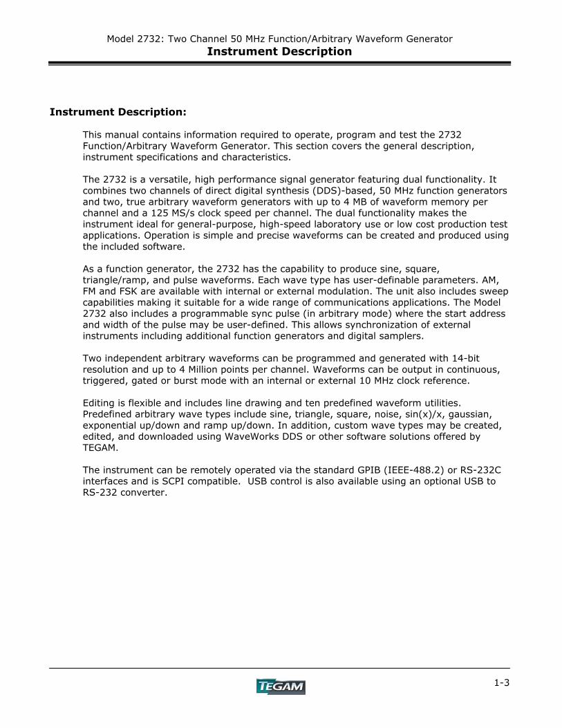
This manual contains information required to operate, program and test the 2732 Function/Arbitrary Waveform Generator. This section covers the general description, instrument specifications and characteristics. The 2732 is a versatile, high performance signal generator featuring dual functionality. It combines two channels of direct digital synthesis (DDS)-based, 50 MHz function generators and two, true arbitrary waveform generators with up to 4 MB of waveform memory per channel and a 125 MS/s clock speed per channel. The dual functionality makes the instrument ideal for general-purpose, high-speed laboratory use or low cost production test applications. Operation is simple and precise waveforms can be created and produced using the included software. As a function generator, the 2732 has the capability to produce sine, square, triangle/ramp, and pulse waveforms. Each wave type has user-definable parameters. AM, FM and FSK are available with internal or external modulation. The unit also includes sweep capabilities making it suitable for a wide range of communications applications. The Model 2732 also includes a programmable sync pulse (in arbitrary mode) where the start address and width of the pulse may be user-defined. This allows synchronization of external instruments including additional function generators and digital samplers. Two independent arbitrary waveforms can be programmed and generated with 14-bit resolution and up to 4 Million points per channel. Waveforms can be output in continuous, triggered, gated or burst mode with an internal or external 10 MHz clock reference. Editing is flexible and includes line drawing and ten predefined waveform utilities. Predefined arbitrary wave types include sine, triangle, square, noise, sin(x)/x, gaussian, exponential up/down and ramp up/down. In addition, custom wave types may be created, edited, and downloaded using WaveWorks DDS or other software solutions offered by TEGAM. The instrument can be remotely operated via the standard GPIB (IEEE-488.2) or RS-232C interfaces and is SCPI compatible. USB control is also available using an optional USB to RS-232 converter.
Model 2732: Two Channel 50 MHz Function/Arbitrary Waveform Generator Instrument Description
1-4
Feature Overview DDS Flexibility with Arbitrary Waveform Precision
TEGAM’s 2732 combines the advantages of a true arbitrary waveform generator with the advantages of a direct digital synthesis (DDS) generator. Its proprietary design makes the 2732 extremely versatile for sweep, modulation, pulse, and integration applications without losing valuable arbitrary wave data through unnecessary digital processing.
Standard Waveforms from 1 μHz to 50 MHz
In the function generator mode, sine and square waves are available from 1 μHz to 50 MHz. Triangle/ramp waveforms are available from 1 μHz to 5 MHz. Pulse waveforms may be produced from 500 μHz to 25 MHz.
Internal/External AM, FM, or FSK functions
Model 2730 has the capability to modulate standard waveforms from an internal or external, 0 V to 5 V source. AM & FM are available from 0.01 Hz to 20 kHz. FSK is available from 0.01 Hz to 1 MHz internally and limited to 1 MHz externally.
Arbitrary Wave Creation
In addition to operating as a function generator, the 2730 may be operated in its arbitrary waveform mode. Custom waveforms may be imported, created or edited using WaveWorks DDS software or the instrument’s front panel. The user defines the range (any segment between 1 to 4,000,000) of arbitrary wave data to be executed.
Wave Creation Software Windows–based, WaveWorks DDS is provided at no additional charge. The user can create, import, edit, download/upload data to/from the instrument using WaveWorks DDS. WaveWorks DDS also has the ability to download wave data directly from select Tektronix, Agilent, and LeCroy oscilloscopes.
0.01 Hz to 125 MS/s Sampling Speed The execution of arbitrary wave data can be varied from .01 Hz to 125 MS/s. The wide sampling range offers exceptional flexibility for wave data storage and execution.
8 MB of Arbitrary Wave Memory (4MB x 2 Channels)
The Model 2732 offers two channels of 4 MB wave memory enabling up to 4 Million points of data per waveform per channel. No other function/arbitrary waveform generator in its class offers this much memory. Programmable Synchronous Output (Marker) In arbitrary wave mode, a fully programmable TTL marker pulse allows external synchronization with arbitrary waveform data points. The width and starting address of the pulse are user-defined between address locations 1 through 4,000,000.
RS-232C and GPIB Interfaces GPIB and RS-232C interfaces are included at no additional charge. 3-Year Warranty TEGAM stands behind this product and backs it with a full 3-year warranty.

Model 2732: Two Channel 50 MHz Function/Arbitrary Waveform Generator Instrument Description
1-5
Model 2732 Accessories
2701 – Single Unit Rack Mount Kit Fits most standard 19” racks. Mounting
hardware included.
2702 – Dual Unit Rack Mount Kit
Fits most standard 19” racks. Mounting hardware included.
CBL-3102 – BNC Cable
3-ft BNC cable used for general purpose I/O connections.
BNC-3285 – BNC (F-M-F)
BNC Tee Connector Used for splitting 50 Ω, BNC-type connections
used for trigger, main output, modulation, and sync I/O’s.
1583-3 – 3ft Heavy Duty GPIB Cable 1583-6 – 6ft Heavy Duty GPIB Cable 1583-9 – 9ft Heavy Duty GPIB Cable
2732-901-01 – 2732 User’s Manual
Printed Version
1000030-840-01
• 2732 User’s Manual • WaveWorks DDS Wave Creation
Software • LabVIEW Drivers
(Included Accessories)
740565-6 - 6 ft RS-232C Cable
DB9F to DB9F RS-232C, null modem communication cable for the Model 2732.
(Included Accessory)
161006600 – Power Cord for 120 VAC
Operation Contact TEGAM for alternate voltages.
(Included Accessory)
1000001 - USB to RS232 Converter Allows serial communication between the Model 2732 RS232 interface and a USB
enabled PC. Kit includes software driver for Windows 98SE/ME/2000/XP, Mac 8.6/9/10,
and Linux 2.4 and higher.
Model 2732: Two Channel 50 MHz Function/Arbitrary Waveform Generator Instrument Description
1-6
2732 Performance Specifications (Channel Independent):
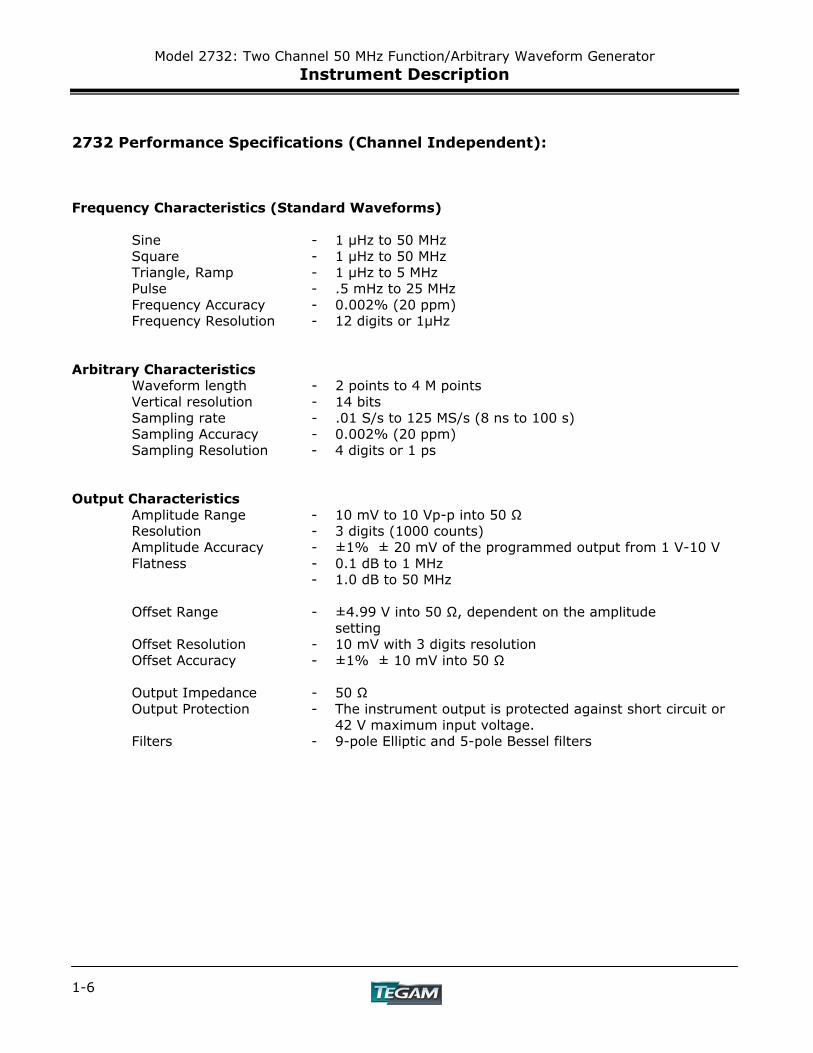
Frequency Characteristics (Standard Waveforms) Sine - 1 μHz to 50 MHz Square - 1 μHz to 50 MHz Triangle, Ramp - 1 μHz to 5 MHz Pulse - .5 mHz to 25 MHz Frequency Accuracy - 0.002% (20 ppm) Frequency Resolution - 12 digits or 1μHz Arbitrary Characteristics Waveform length - 2 points to 4 M points Vertical resolution - 14 bits Sampling rate - .01 S/s to 125 MS/s (8 ns to 100 s) Sampling Accuracy - 0.002% (20 ppm) Sampling Resolution - 4 digits or 1 ps Output Characteristics Amplitude Range - 10 mV to 10 Vp-p into 50 Ω Resolution - 3 digits (1000 counts) Amplitude Accuracy - ±1% ± 20 mV of the programmed output from 1 V-10 V Flatness - 0.1 dB to 1 MHz - 1.0 dB to 50 MHz Offset Range - ±4.99 V into 50 Ω, dependent on the amplitude setting Offset Resolution - 10 mV with 3 digits resolution Offset Accuracy - ±1% ± 10 mV into 50 Ω Output Impedance - 50 Ω
Output Protection - The instrument output is protected against short circuit or 42 V maximum input voltage.
Filters - 9-pole Elliptic and 5-pole Bessel filters
Model 2732: Two Channel 50 MHz Function/Arbitrary Waveform Generator Instrument Description
1-7
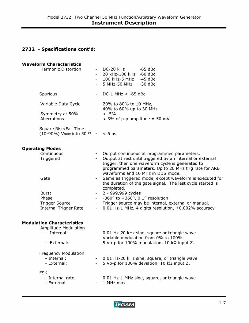
2732 - Specifications cont’d: Waveform Characteristics Harmonic Distortion - DC-20 kHz -65 dBc - 20 kHz-100 kHz -60 dBc - 100 kHz-5 MHz -45 dBc - 5 MHz-50 MHz -30 dBc Spurious - DC-1 MHz < -65 dBc Variable Duty Cycle - 20% to 80% to 10 MHz, 40% to 60% up to 30 MHz Symmetry at 50% - < .5% Aberrations - < 3% of p-p amplitude ± 50 mV. Square Rise/Fall Time (10-90%) Vmax into 50 Ω - < 6 ns Operating Modes Continuous - Output continuous at programmed parameters.
Triggered - Output at rest until triggered by an internal or external trigger, then one waveform cycle is generated to programmed parameters. Up to 20 MHz trig rate for ARB waveforms and 10 MHz in DDS mode.
Gate - Same as triggered mode, except waveform is executed for the duration of the gate signal. The last cycle started is completed.
Burst - 2 - 999,999 cycles Phase - -360° to +360°, 0.1° resolution
Trigger Source - Trigger source may be internal, external or manual. Internal Trigger Rate - 0.01 Hz-1 MHz, 4 digits resolution, ±0.002% accuracy Modulation Characteristics Amplitude Modulation - Internal: - 0.01 Hz-20 kHz sine, square or triangle wave Variable modulation from 0% to 100%. - External: - 5 Vp-p for 100% modulation, 10 kΩ input Z. Frequency Modulation - Internal: - 0.01 Hz-20 kHz sine, square, or triangle wave
- External: - 5 Vp-p for 100% deviation, 10 kΩ input Z. FSK - Internal rate - 0.01 Hz-1 MHz sine, square, or triangle wave - External - 1 MHz max
Model 2732: Two Channel 50 MHz Function/Arbitrary Waveform Generator Instrument Description
1-8
2732 - Specifications cont’d:
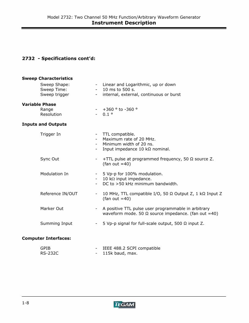
Sweep Characteristics Sweep Shape: - Linear and Logarithmic, up or down Sweep Time: - 10 ms to 500 s. Sweep trigger - internal, external, continuous or burst Variable Phase Range - +360 ° to -360 ° Resolution - 0.1 ° Inputs and Outputs Trigger In - TTL compatible. - Maximum rate of 20 MHz. - Minimum width of 20 ns. - Input impedance 10 kΩ nominal.
Sync Out - +TTL pulse at programmed frequency, 50 Ω source Z. (fan out =40) Modulation In - 5 Vp-p for 100% modulation. - 10 kΩ input impedance. - DC to >50 kHz minimum bandwidth. Reference IN/OUT - 10 MHz, TTL compatible I/O, 50 Ω Output Z, 1 kΩ Input Z (fan out =40)
Marker Out - A positive TTL pulse user programmable in arbitrary waveform mode. 50 Ω source impedance. (fan out =40)
Summing Input - 5 Vp-p signal for full-scale output, 500 Ω input Z.
Computer Interfaces: GPIB - IEEE 488.2 SCPI compatible RS-232C - 115k baud, max.
Model 2732: Two Channel 50 MHz Function/Arbitrary Waveform Generator Instrument Description
1-9
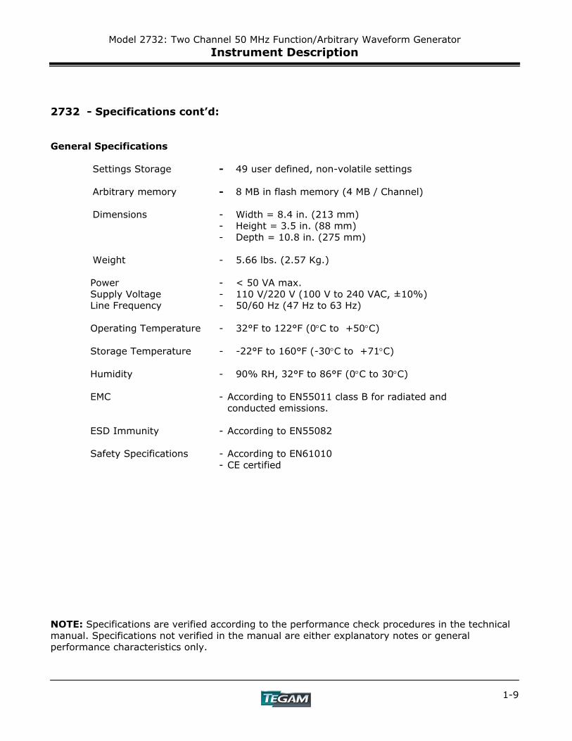
2732 - Specifications cont’d: General Specifications Settings Storage - 49 user defined, non-volatile settings Arbitrary memory - 8 MB in flash memory (4 MB / Channel) Dimensions - Width = 8.4 in. (213 mm) - Height = 3.5 in. (88 mm) - Depth = 10.8 in. (275 mm) Weight - 5.66 lbs. (2.57 Kg.) Power - < 50 VA max. Supply Voltage - 110 V/220 V (100 V to 240 VAC, ±10%) Line Frequency - 50/60 Hz (47 Hz to 63 Hz) Operating Temperature - 32°F to 122°F (0°C to +50°C) Storage Temperature - -22°F to 160°F (-30°C to +71°C) Humidity - 90% RH, 32°F to 86°F (0°C to 30°C) EMC - According to EN55011 class B for radiated and conducted emissions. ESD Immunity - According to EN55082 Safety Specifications - According to EN61010 - CE certified NOTE: Specifications are verified according to the performance check procedures in the technical manual. Specifications not verified in the manual are either explanatory notes or general performance characteristics only.

Model 2732: Two Channel 50 MHz Function/Arbitrary Waveform Generator Instrument Description
1-10
Preparation for Use
INSTRUMENT DESCRIPTION PREPARATION FOR USE
QUICK START INSTRUCTIONS OPERATING INSTRUCTIONS
PROGRAMMING & INTERFACING SERVICE INFORMATION
APPENDIX Model 2732: Two Channel 50 MHz Function/Arbitrary Waveform Generator 2-1

Model 2732: Two Channel 50 MHz Function/Arbitrary Waveform Generator Preparation for Use
2-2
Model 2732: Two Channel 50 MHz Function/Arbitrary Waveform Generator Preparation for Use
2-3
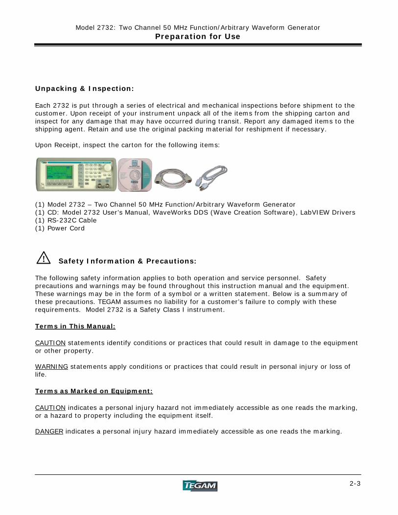
Unpacking & Inspection: Each 2732 is put through a series of electrical and mechanical inspections before shipment to the customer. Upon receipt of your instrument unpack all of the items from the shipping carton and inspect for any damage that may have occurred during transit. Report any damaged items to the shipping agent. Retain and use the original packing material for reshipment if necessary. Upon Receipt, inspect the carton for the following items:
(1) Model 2732 – Two Channel 50 MHz Function/Arbitrary Waveform Generator (1) CD: Model 2732 User’s Manual, WaveWorks DDS (Wave Creation Software), LabVIEW Drivers (1) RS-232C Cable (1) Power Cord Safety Information & Precautions: The following safety information applies to both operation and service personnel. Safety precautions and warnings may be found throughout this instruction manual and the equipment. These warnings may be in the form of a symbol or a written statement. Below is a summary of these precautions. TEGAM assumes no liability for a customer’s failure to comply with these requirements. Model 2732 is a Safety Class I instrument. Terms in This Manual: CAUTION statements identify conditions or practices that could result in damage to the equipment or other property. WARNING statements apply conditions or practices that could result in personal injury or loss of life. Terms as Marked on Equipment: CAUTION indicates a personal injury hazard not immediately accessible as one reads the marking, or a hazard to property including the equipment itself. DANGER indicates a personal injury hazard immediately accessible as one reads the marking.
!
Model 2732: Two Channel 50 MHz Function/Arbitrary Waveform Generator Preparation for Use
2-4
! Safety Information & Precautions Cont’d:
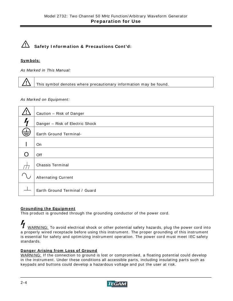
Symbols: As Marked in This Manual:
! This symbol denotes where precautionary information may be found.
As Marked on Equipment:
!
Caution – Risk of Danger
Danger – Risk of Electric Shock
Earth Ground Terminal-
l On
O Off
Chassis Terminal
Alternating Current
Earth Ground Terminal / Guard
Grounding the Equipment This product is grounded through the grounding conductor of the power cord.
WARNING: To avoid electrical shock or other potential safety hazards, plug the power cord into a properly wired receptacle before using this instrument. The proper grounding of this instrument is essential for safety and optimizing instrument operation. The power cord must meet IEC safety standards. Danger Arising from Loss of Ground WARNING: If the connection to ground is lost or compromised, a floating potential could develop in the instrument. Under these conditions all accessible parts, including insulating parts such as keypads and buttons could develop a hazardous voltage and put the user at risk.

Model 2732: Two Channel 50 MHz Function/Arbitrary Waveform Generator Preparation for Use
2-5
!
! Use the Proper Fuse To avoid fire hazard, use only the correct fuse type as specified for the AC power supply in the “Preparation for Use” or “Service” sections of this manual. Note that the fuse rating for 100-volt and 120-volt operation is different than the rating for 200-volt and 240-volt operation. Information about the proper fuse type is also printed on the rear panel of the instrument. Refer fuse replacement to qualified service personnel. Do Not Use in Explosive Environments WARNING: The 2732 is not designed for operation in explosive environments. Do not Operate Without Covers WARNING: This device should be operated with all panels and covers in place. Operation with missing panels or covers could result in personal injury.
FOR QUALIFIED SERVICE PERSONNEL ONLY
Servicing Safety Summary:
Do Not Service Alone Do not perform service or adjustment on this product unless another person capable of rendering first aid is present. Use Care When Servicing with Power On or Off Dangerous voltages may exist at several points in this product. To avoid personal injury or damage to this equipment, avoid touching exposed connections or components while the power is on. Assure that the power is off by unplugging the instrument when removing panels, soldering, or replacing components.
WARNING: The instrument power source is electronically controlled meaning that there is power present throughout the instrument even when the instrument is in the OFF state. Always unplug the instrument and wait 5 minutes before accessing internal components. Power Source This product is intended to connect to a power source that will not apply more than 264 V RMS between the supply conductors or between either of the supply conductors and ground. A protective ground connection by way of the grounding conductor in the power cord is essential for safe operation.
Model 2732: Two Channel 50 MHz Function/Arbitrary Waveform Generator Preparation for Use
2-6
!
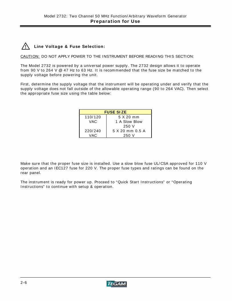
Line Voltage & Fuse Selection:
CAUTION: DO NOT APPLY POWER TO THE INSTRUMENT BEFORE READING THIS SECTION: The Model 2732 is powered by a universal power supply. The 2732 design allows it to operate from 90 V to 264 V @ 47 Hz to 63 Hz. It is recommended that the fuse size be matched to the supply voltage before powering the unit. First, determine the supply voltage that the instrument will be operating under and verify that the supply voltage does not fall outside of the allowable operating range (90 to 264 VAC). Then select the appropriate fuse size using the table below:
FUSE SIZE 110/120
VAC 5 X 20 mm
1 A Slow Blow 250 V
220/240 VAC
5 X 20 mm 0.5 A 250 V
Make sure that the proper fuse size is installed. Use a slow blow fuse UL/CSA approved for 110 V operation and an IEC127 fuse for 220 V. The proper fuse types and ratings can be found on the rear panel. The instrument is ready for power up. Proceed to “Quick Start Instructions” or “Operating Instructions” to continue with setup & operation.

Quick Start Instructions
INSTRUMENT DESCRIPTION PREPARATION FOR USE
QUICK START INSTRUCTIONS OPERATING INSTRUCTIONS
PROGRAMMING & INTERFACING SERVICE INFORMATION
APPENDIX Model 2732: Two Channel 50 MHz Function/Arbitrary Waveform Generator 3-1

Model 2732: Two Channel 50 MHz Function/Arbitrary Waveform Generator Quick Start Instructions
3-2
Model 2732: Two Channel 50 MHz Function/Arbitrary Waveform Generator Quick Start Instructions
3-3
Introduction The Model 2732 is a versatile product, which can be used in many different configurations. Virtually any wave type can be created and produced at the instrument’s output. Because of its ability to operate as a function generator or arbitrary waveform generator it is highly recommended that the entire “Operating Instructions” Section of this manual be reviewed to insure the most efficient use of the instrument. Generally speaking, function generator operation from the front panel or arbitrary wave creation using WaveWorks DDS are relatively simple procedures. These are described in this section along with practical examples. Arbitrary wave creation or editing from the instrument’s front panel are more tedious tasks and are included in the “Operating Instructions” section only. The Quick Start section is designed to give the user a general instruction set for the speedy setup and generation of common wave types. A reference is sometimes made to other parts of this manual so that the user, at their discretion, can decide whether or not to pursue additional information. Power the Unit The universal power supply of Model 2732 is designed for 50-60 Hz operation and a voltage range of 90-264 VAC. It is assumed that the “Preparation for Use” section of this manual has been read and understood and the line voltage and fuse type has been verified to be correct. Power the unit by depressing the pushbutton located on the lower left corner of the front panel. Verify that the unit will be operated in the operating environment as defined in the specifications. Your First Waveform The 2732’s intuitive design allows a waveform to be produced at the instrument’s output with the stroke of a few keys. The example below demonstrates how to use the instrument as a standard function generator.
1. Power the unit and allow it to initialize. 2. Press the [CHAN] key to toggle between Channel 1 or Channel 2 parameters. 3. Press [WAVE] and select the desired waveform. 4. Press the [ON] key above the associated Output BNC connector: CH 1 or CH 2. 5. Observe the output waveform. 6. Press the [PARAM] key. 7. Turn the dial and adjust the output frequency. 8. Press F3:[AMPL] and adjust the amplitude. 9. Press F3:[OFST] again and adjust the offset voltage. 10. Verify the waveform’s amplitude and offset with an oscilloscope. Use a 50 Ω termination at
the scope’s input.
Model 2732: Two Channel 50 MHz Function/Arbitrary Waveform Generator Quick Start Instructions
3-4
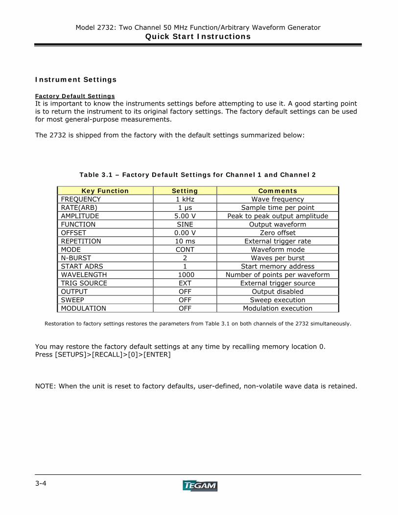
Instrument Settings Factory Default Settings It is important to know the instruments settings before attempting to use it. A good starting point is to return the instrument to its original factory settings. The factory default settings can be used for most general-purpose measurements. The 2732 is shipped from the factory with the default settings summarized below:
Table 3.1 – Factory Default Settings for Channel 1 and Channel 2
Key Function Setting Comments FREQUENCY 1 kHz Wave frequency RATE(ARB) 1 μs Sample time per point AMPLITUDE 5.00 V Peak to peak output amplitude FUNCTION SINE Output waveform OFFSET 0.00 V Zero offset REPETITION 10 ms External trigger rate MODE CONT Waveform mode N-BURST 2 Waves per burst START ADRS 1 Start memory address WAVELENGTH 1000 Number of points per waveform TRIG SOURCE EXT External trigger source OUTPUT OFF Output disabled SWEEP OFF Sweep execution MODULATION OFF Modulation execution
Restoration to factory settings restores the parameters from Table 3.1 on both channels of the 2732 simultaneously.
You may restore the factory default settings at any time by recalling memory location 0. Press [SETUPS]>[RECALL]>[0]>[ENTER] NOTE: When the unit is reset to factory defaults, user-defined, non-volatile wave data is retained.
Model 2732: Two Channel 50 MHz Function/Arbitrary Waveform Generator Quick Start Instructions
3-5
Using the Function Generator Changing Channels: Channel selection is performed by pressing the [CHAN] button, this key toggles between Channel 1 and Channel 2. Channel settings are independent and stay in memory while changing channels Parameter Key [PARAM] – Once the desired wave function is selected, pressing this key displays the basic function or arbitrary waveform parameters, which include frequency, amplitude, offset and int/ext reference clock mode. The parameters may be modified by accessing the soft keys on the bottom of the display. The active parameters are highlighted in black. In the Arbitrary Waveform mode, the sampling rate can also be viewed or modified. Enter new parameter values by:
Typing in a numeric value and then pressing [ENTER]. For immediate changes at the instrument’s output, adjust the rotary dial in
combination with use of the left and right arrow keys.
Waveform Key [WAVE] – Pressing this key displays the wave menu. You can choose from sine, square, triangle (ramp), pulse, or arbitrary wave types by pressing [F1]:SINE, [F2]:SQR, [F3]:TRI, [F4]:PULSE OR [F5]:ARB. The active wave type is highlighted in black. Pressing the soft key will enable the respective wave type. Pressing the [ON] key located above channel 1 or Channel 2 will either enable or disable the main output on each respective channel. The output status is indicated on the upper right hand corner of the LCD by a CH1 or CH2 indicator. A darkened channel status is defined as an active output channel. Trigger Menu [MODE] - Access the trigger menu by pressing this key. There are five options available from the trigger menu. These are:
[F1]:CONT Enables the continuous triggering mode. [F2]:TRIG Chooses either a manual, internal or external trigger source. [F3]:GATE Allows the output to be gated via manual, internal, or external trigger. [F4]:BURST Allows the number of bursts (2-999,999) to be programmed and
chooses manual, internal or external triggered burst. [F5]:PHASE Allows a non-continuous triggered waveform to start at the specified
phase. Sweep Menu [SWEEP] - There is no sweep function for the arbitrary waveform mode. Enable the sweep function by pressing this key and then enter the required parameters for the sweep function. The user defines the start and stop addresses and the rate at which one complete sweep occurs. A linear or logarithmic sweep may be specified.
Model 2732: Two Channel 50 MHz Function/Arbitrary Waveform Generator Quick Start Instructions
3-6
Using the Function Generator cont’d: Modulation [MODUL] - Press this key to access the modulation menu. For arbitrary waveforms, only AM modulation is available. For function generator waveforms, AM, FM, and FSK are available.
[F1]:AM Chooses amplitude modulation and allows the user to define %
modulation, modulation shape, and the frequency of modulation. [F3]:FM Accesses the frequency modulation menu, which allows selection of
deviation frequency, modulation shape, and the modulation frequency.
[F5]:FSK Accesses the frequency shift keying menu where low and high
frequencies and the rate of change between these frequencies may be defined.
Setups [SETUPS] - Up to 49 (from 1 to 49) system setups may be stored in the 2732. Location zero is reserved for factory defaults and location 50 is reserved for the last settings before the unit was powered down. Simply choose to recall or to store a memory location by pressing the [F1]:RECALL OR [F3]:STORE keys, entering which location to read or write to, and then pressing [ENTER] to activate or save the specified settings. *When a setup is stored, Channel 1 and Channel 2 settings are stored simultaneously into a single memory location. Utility [UTIL] – Press this key to access the utility menu. The utility menu allows the user to:
[F1]:GPIB Selects the GPIB address of the 2732 and enables GPIB operation. [F2]:RS232 Sets the RS232 baud rate and enables RS-232C operation.
[F3]:INTEN Sets the LCD intensity.
[F4]:POWER Defines which stored setup will resume on every power up.
Model 2732: Two Channel 50 MHz Function/Arbitrary Waveform Generator Quick Start Instructions
3-7
Downloading a Waveform from WaveWorks DDS to the Instrument
1) Start WaveWorks DDS by double-clicking the icon.
2) Select the instrument model number by pressing File>Instruments>Model 2732. 3) Create the desired waveform by using the tools in WaveWorks DDS or importing a *.txt
data file.
4) Connect the supplied serial cable between the Model 2732 and the serial port on your computer.
5) Define the RS-232 settings in WaveWorks DDS by pressing Communication>Send
Waveform>RS-232.
a. Set the channel to either Channel 1 or Channel 2. b. Define the start and length of the waveform data. c. Set the port number and baud rate. (use 19200 for this example)
6) On the 2732, press [UTIL]>[RS-232], set the baud to 19200 and press [ENTER]. Confirm
that the 2732 instrument settings match WaveWorks settings. 7) Press the send button in the WaveWorks DDS “Send Waveform” screen.
8) The wave data created by WaveWorks DDS will download to the arb.

Model 2732: Two Channel 50 MHz Function/Arbitrary Waveform Generator Quick Start Instructions
3-8
Using WaveWorks DDS to Create an Arbitrary Waveform WaveWorks DDS is a basic wave creation tool offered as a standard accessory for TEGAM models 2720, 2725, 2730, and 2732 function/arbitrary waveform generators. With WaveWorks DDS, the user has the ability to create, modify and download a customized waveform using up to 9 standard waveform templates, a freehand drawing tool, insert function and other editing tools. For more information on WaveWorks DDS and other advanced arbitrary waveform creation and editing software, contact your local TEGAM sales office. The example below demonstrates the basic use of WaveWorks DDS software. Designed specifically for TEGAM’s DDS based function/arbitrary generators, WaveWorks DDS eliminates the need for front panel wave editing, which can be tedious and time consuming. The exercise below demonstrates the creation of a 1 kHz, sine wave burst of 3 complete cycles. The frequency of the entire arbitrary waveform (including the three sine bursts) is 200 Hz.
Build the Waveform
1. Start WaveWorks DDS 2. Press File>Instruments>Model 2732 3. Click on INSERT>SINE… 4. Select Start Point = 1, Length = 1000, Scale = 0.50, Offset = 0.00 5. Click on INSERT>SINE 6. Select Start Point = 1001, Length = 1000, Scale = 0.50, Offset = 0.00 7. Click on INSERT>SINE 8. Select Start Point = 2001, Length = 1000, Scale = 0.50, Offset = 0.00 9. Click on INSERT>DC 10. Select Start Point = 3001, Length = 2000, Scale = N/A, Offset = 0.00 11. Click on COMMUNICATION>SEND WAVEFORM>RS232
NOTE: Be sure to use the proper RS-232 communications cable type Select Channel 1, Start Point = 1, Length = 5000
12. Select PORT = COM1, Baud Rate = 19200 (make sure the instrument is set for 19,200)
13. Apply power to 2732 14. On the 2732, press [UTIL]>[F2]:RS232, set Baud = 19200 using rotary knob 15. Click “Send” In the WaveWorks DDS window. 16. Wave data will be transmitted to the Model 2732. The message “Remotely Controlled
– RS232” will be displayed on the Model 2732’s display.
Display of the Waveform on an Oscilloscope:
Channel 1 on the 2732 will output the created wave as it is being downloaded to an attached oscilloscope via a standard BNC connected cable. Once downloading is complete, control will be returned to the instrument’s front panel and the wave in it’s entirety will be displayed.
Model 2732: Two Channel 50 MHz Function/Arbitrary Waveform Generator Quick Start Instructions
3-9
General Tips for Usage Connecting to the Main Output Use a good quality BNC cable to connect to the main output. Verify that the load impedance is 50Ω. Load impedances higher than 50Ω will result in higher output magnitudes and reflections in the output at high frequencies. Impedances lower than 50Ω will result in lower output magnitudes than programmed in the instrument. Function Generator Operation Operating the 2732 as a function generator is best performed using the instrument’s front panel. Pressing the [PARAM] key allows user definable access to waveform parameters. Arbitrary Wave Creation Arbitrary wave creation can be performed by using the 2732 front panel keys or with WaveWorks DDS software. The frequency of an arbitrary waveform is determined by dividing the sample rate by the number of samples used for one cycle. The output amplitude is determined by the percentage of full scale of the arbitrary wave times the programmed amplitude of the output. See the example in section 4 titled, “Setting the Frequency” for more details. Waveform and Execution Memory The waveform generator uses two forms of memory. These are Dynamic RAM for defining, editing and generating arbitrary waveforms and non-volatile flash memory for storing arbitrary waveform data and front panel settings when the instrument is off. Both dynamic RAM and non-volatile flash memories consist of 4,000,000 points per channel at which you can specify a value from -8192 to +8192. You can scale these points through the output amplitude setting; that is, data point 8192 is equal to the positive peak (Scale = 1.0) of the user-defined output amplitude. Additional Examples Examples for creating and editing arbitrary waveforms are located in the “Operating Instructions” section of this manual.

Model 2732: Two Channel 50 MHz Function/Arbitrary Waveform Generator Quick Start Instructions
3-10
Operating Instructions
INSTRUMENT DESCRIPTION PREPARATION FOR USE
QUICK START INSTRUCTIONS OPERATING INSTRUCTIONS
PROGRAMMING & INTERFACING SERVICE INFORMATION
APPENDIX Model 2732: Two Channel 50 MHz Function/Arbitrary Waveform Generator 4-1

Model 2732: Two Channel 50 MHz Function/Arbitrary Waveform Generator Operating Instructions
4-2
Model 2732: Two Channel 50 MHz Function/Arbitrary Waveform Generator Operating Instructions
4-3
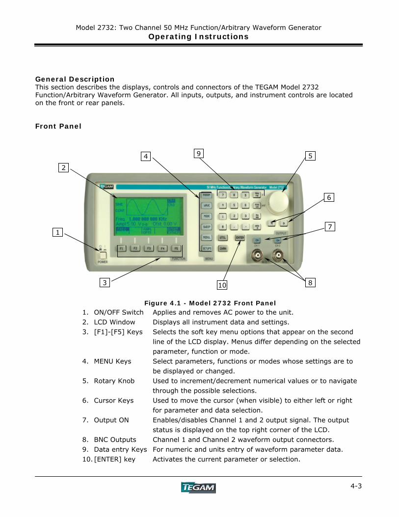
General Description This section describes the displays, controls and connectors of the TEGAM Model 2732 Function/Arbitrary Waveform Generator. All inputs, outputs, and instrument controls are located on the front or rear panels. Front Panel
Figure 4.1 - Model 2732 Front Panel 1. ON/OFF Switch Applies and removes AC power to the unit. 2. LCD Window Displays all instrument data and settings. 3. [F1]-[F5] Keys Selects the soft key menu options that appear on the second
line of the LCD display. Menus differ depending on the selected parameter, function or mode.
4. MENU Keys Select parameters, functions or modes whose settings are to be displayed or changed.
5. Rotary Knob Used to increment/decrement numerical values or to navigate through the possible selections.
6. Cursor Keys Used to move the cursor (when visible) to either left or right for parameter and data selection.
7. Output ON Enables/disables Channel 1 and 2 output signal. The output status is displayed on the top right corner of the LCD.
8. BNC Outputs Channel 1 and Channel 2 waveform output connectors. 9. Data entry Keys For numeric and units entry of waveform parameter data. 10. [ENTER] key Activates the current parameter or selection.
10
1
2
4 5
6
7
8
9
3 10
Model 2732: Two Channel 50 MHz Function/Arbitrary Waveform Generator Operating Instructions
4-4
Display Window The Model 2732 has a graphic LCD display that can display 160x80 dots. When you power the unit, a parameter (Frequency) and its current settings appear in the display. There is also a graphical representation of the current waveform on the LCD. A soft key menu is located on the bottom of the LCD that corresponds to the function, parameter or mode selected.
Front Panel Controls The front-panel controls select, display, and change parameter, function, and mode settings. They also include the keys used to program and generate a waveform output. Use the rotary input knob and the cursor movement keys to enter data into the waveform generator. To change a setting:
1. Press the appropriate function/parameter/mode key. 2. Use the [◄] [►] keys to adjust the cursor position 3. Use the rotary input or the numerical/units keyboard to change the value of the
displayed item. Changes take effect immediately, or after the [ENTER] or units keys are pressed.
Front Panel Output Connectors The 2732 function/arbitrary generator has two BNC connectors on the front panel, CH 1 and CH 2 OUTPUT.
Channel 1 Output Connector Use this connector to transfer the Channel 1 output signal from the function generator to a compatible (50 Ω) load. Use the CH 1 [ON] key to enable or disable the output. An annunciator, Ch 1 appears in the upper right hand corner of the LCD when the output for Channel 1 is enabled. Channel 2 Output Connector Use this connector to transfer the Channel 2 output signal from the function generator to a compatible (50 Ω) load. Use the CH 2 [ON] key to enable or disable the output. An annunciator, Ch 2 appears in the upper right hand corner of the LCD when the output for Channel 2 is enabled.
Model 2732: Two Channel 50 MHz Function/Arbitrary Waveform Generator Operating Instructions
4-5
Rear Panel
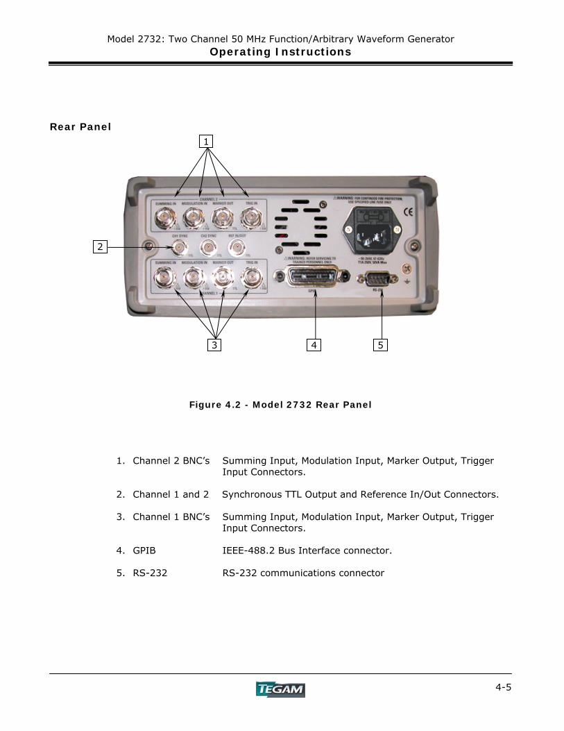
Figure 4.2 - Model 2732 Rear Panel
1. Channel 2 BNC’s Summing Input, Modulation Input, Marker Output, Trigger Input Connectors.
2. Channel 1 and 2 Synchronous TTL Output and Reference In/Out Connectors. 3. Channel 1 BNC’s Summing Input, Modulation Input, Marker Output, Trigger
Input Connectors. 4. GPIB IEEE-488.2 Bus Interface connector. 5. RS-232 RS-232 communications connector
1
3 5 4
2
Model 2732: Two Channel 50 MHz Function/Arbitrary Waveform Generator Operating Instructions
4-6
Rear Panel Input Connectors The 2732 rear panel has seven input BNC connectors. Channel 1 and channel 2 have independent SUMMING IN, MODULATION IN, and TRIG IN, The 2732 shares a common REF IN/OUT.
Summing In Connectors (2) Use these connectors to apply an external analog signal that will be added to the output waveform. A 5 Vp-p signal is required for full-scale output. The input impedance is 500 Ω. Modulation In Connectors (2) Can accept a 5 Vp-p signal for 100% modulation, 10 kΩ input impedance with DC-20 kHz minimum bandwidth. Trigger In Connectors (2) Use these connectors to apply positive external TTL triggers or gate signals, depending on the waveform generators settings, to the generator. Ref In/Out Connector When the 2732 is in “External Reference Mode”, this connector is used as an input from an externally generated 10 MHz signal. In the “Internal Reference Mode”, the input becomes a 10 MHz output.
Rear Panel Output Connectors The rear panel has five output BNC connectors, (2) MARKER OUT, (1)REF OUT, and (2) SYNC OUT.
Marker Output Connectors (2) These connectors output a positive TTL marker pulse when the 2732 is in arbitrary waveform mode. The marker position and width can be programmed by the user and is relative to the data points in the arbitrary waveform memory. The output is disabled when the 2732 is in function generator mode or when an inactive address is defined. There is a separate marker output for both channel 1 and channel 2. Ref In/Out Connector When the 2732 is in “External Reference Mode”, this connector is used as an input for an externally generated 10 MHz signal. In the “Internal Reference Mode”, the input becomes a 10 MHz output.
Sync Out Connectors These outputs provide positive TTL sync pulses, which are generated at the beginning of each function generator or arbitrary waveform cycle. Its duration is the period of the output waveform at a 50% duty cycle. Parameters other than the frequency/period are fixed. Each channel has it’s own unique synchronization output.
Model 2732: Two Channel 50 MHz Function/Arbitrary Waveform Generator Operating Instructions
4-7
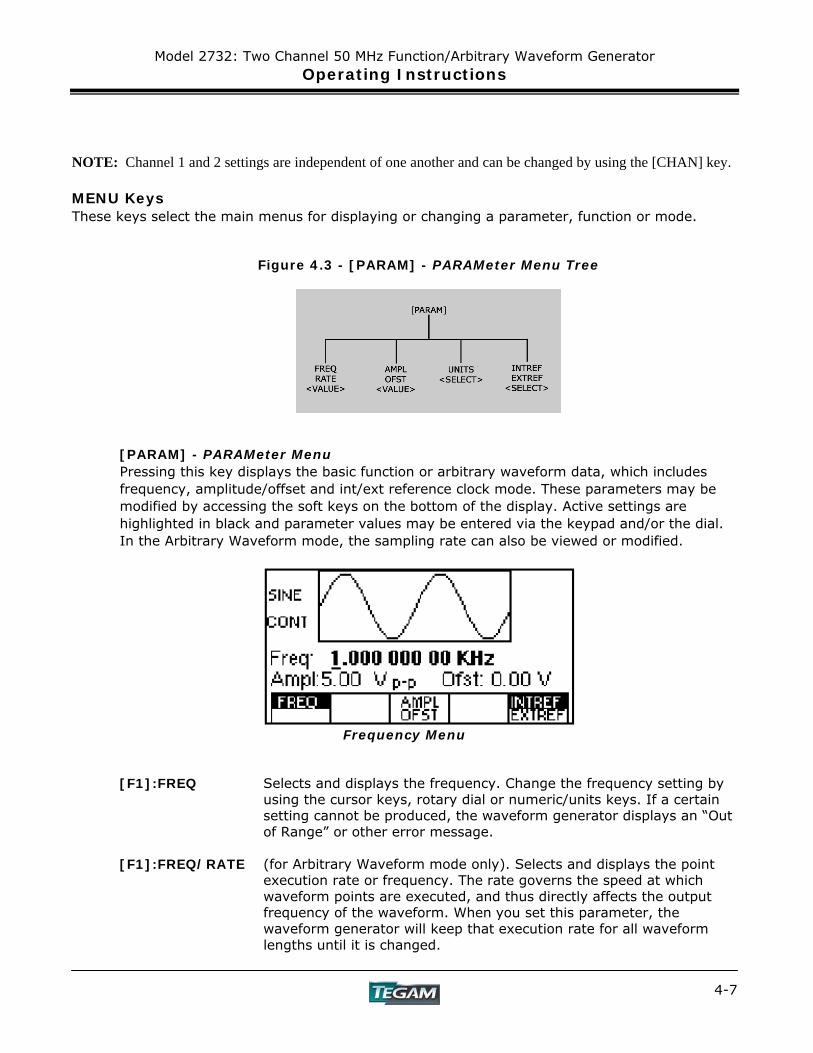
NOTE: Channel 1 and 2 settings are independent of one another and can be changed by using the [CHAN] key. MENU Keys These keys select the main menus for displaying or changing a parameter, function or mode.
Figure 4.3 - [PARAM] - PARAMeter Menu Tree
[PARAM] - PARAMeter Menu Pressing this key displays the basic function or arbitrary waveform data, which includes frequency, amplitude/offset and int/ext reference clock mode. These parameters may be modified by accessing the soft keys on the bottom of the display. Active settings are highlighted in black and parameter values may be entered via the keypad and/or the dial. In the Arbitrary Waveform mode, the sampling rate can also be viewed or modified.
Frequency Menu
[F1]:FREQ Selects and displays the frequency. Change the frequency setting by
using the cursor keys, rotary dial or numeric/units keys. If a certain setting cannot be produced, the waveform generator displays an “Out of Range” or other error message.
[F1]:FREQ/RATE (for Arbitrary Waveform mode only). Selects and displays the point
execution rate or frequency. The rate governs the speed at which waveform points are executed, and thus directly affects the output frequency of the waveform. When you set this parameter, the waveform generator will keep that execution rate for all waveform lengths until it is changed.

Model 2732: Two Channel 50 MHz Function/Arbitrary Waveform Generator Operating Instructions
4-8
MENU Keys cont’d: [PARAM] - PARAMeter Menu cont’d:
[F3]:AMPL/OFST This key toggles between the Amplitude and Offset Settings. AMPL When AMPL is highlighted, the amplitude parameter is selected.
Change the amplitude setting by using the cursor keys, rotary dial or numerical keys. If a certain setting cannot be produced, the waveform generator will display an “Out of Range” or other error message.
The default amplitude is displayed in p-p voltage. However, once the
AMPL function is active the user may select from Vp-p, Vrms, or dBm units by pressing the [F4]:UNITS key.
Setting the Amplitude
The following equation represents the relative output voltage amplitude relationship between the front-panel amplitude peak-to-peak setting and the data point values in waveform memory:
Output voltage = amplitude p-p setting x data point value + offset 16,383
Where 16,383 is the data point value range in waveform memory.
Table 4.1: Waveform Amplitudes (Examples)
Front Panel Amplitude
Setting
Data Point Value
Relative Output Voltage Amplitude
5 Vp-p 8191 +2.5 V 5 Vp-p 4096 +1.25 V 5 Vp-p 0 0V (offset voltage) 9 Vp-p 1200 659 mV 9 Vp-p -4000 -2.197 V 4 Vp-p -8191 -2.0 V
Model 2732: Two Channel 50 MHz Function/Arbitrary Waveform Generator Operating Instructions
4-9
MENU Keys cont’d: [PARAM] - PARAMeter Menu cont’d:
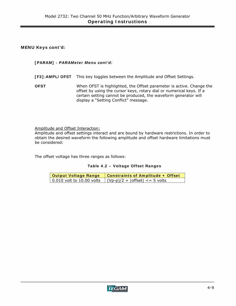
[F3]:AMPL/OFST This key toggles between the Amplitude and Offset Settings. OFST When OFST is highlighted, the Offset parameter is active. Change the
offset by using the cursor keys, rotary dial or numerical keys. If a certain setting cannot be produced, the waveform generator will display a “Setting Conflict” message.
Amplitude and Offset Interaction: Amplitude and offset settings interact and are bound by hardware restrictions. In order to obtain the desired waveform the following amplitude and offset hardware limitations must be considered:
The offset voltage has three ranges as follows:
Table 4.2 – Voltage Offset Ranges
Output Voltage Range Constraints of Amplitude + Offset 0.010 volt to 10.00 volts (Vp-p)/2 + |offset| <= 5 volts
Model 2732: Two Channel 50 MHz Function/Arbitrary Waveform Generator Operating Instructions
4-10
MENU Keys cont’d: [PARAM] - PARAMeter Menu cont’d:
[F4]:UNITS This soft key is only visible after the [F3]: AMPL/OFST key has been
pressed and AMPL is highlighted. Press [F4]: UNITS to toggle between: V p-p, V rms, or dBm as the primary units for Amplitude and Offset values.
[F5]:INT/EXT REF Selects the internal or external clock reference source (the external
reference must be connected to the rear panel Ref In/Out connector). Pressing the [F5] key will toggle between the two reference options.

Model 2732: Two Channel 50 MHz Function/Arbitrary Waveform Generator Operating Instructions
4-11
MENU Keys cont’d:
Figure 4.4 - [WAVE] - WAVE Menu Tree
Model 2732: Two Channel 50 MHz Function/Arbitrary Waveform Generator Operating Instructions
4-12
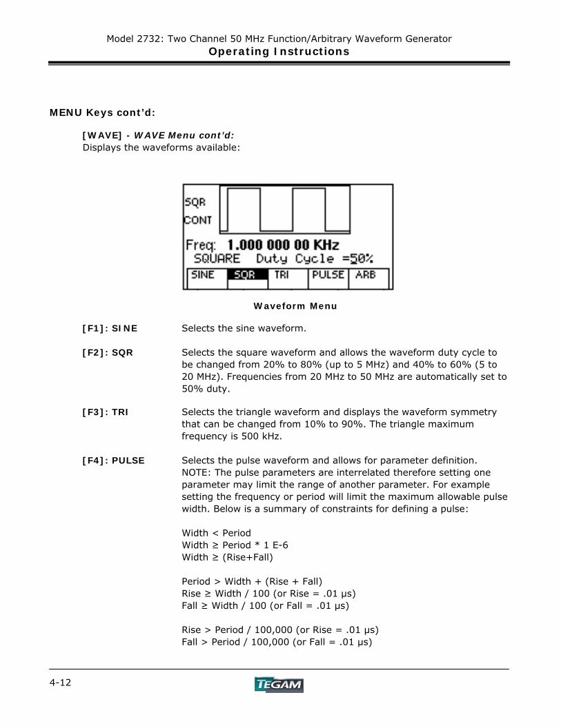
MENU Keys cont’d: [WAVE] - WAVE Menu cont’d: Displays the waveforms available:
Waveform Menu [F1]: SINE Selects the sine waveform. [F2]: SQR Selects the square waveform and allows the waveform duty cycle to
be changed from 20% to 80% (up to 5 MHz) and 40% to 60% (5 to 20 MHz). Frequencies from 20 MHz to 50 MHz are automatically set to 50% duty.
[F3]: TRI Selects the triangle waveform and displays the waveform symmetry
that can be changed from 10% to 90%. The triangle maximum frequency is 500 kHz.
[F4]: PULSE Selects the pulse waveform and allows for parameter definition. NOTE: The pulse parameters are interrelated therefore setting one
parameter may limit the range of another parameter. For example setting the frequency or period will limit the maximum allowable pulse width. Below is a summary of constraints for defining a pulse:
Width < Period Width ≥ Period * 1 E-6 Width ≥ (Rise+Fall) Period > Width + (Rise + Fall) Rise ≥ Width / 100 (or Rise = .01 μs) Fall ≥ Width / 100 (or Fall = .01 μs) Rise > Period / 100,000 (or Rise = .01 µs) Fall > Period / 100,000 (or Fall = .01 µs)
Model 2732: Two Channel 50 MHz Function/Arbitrary Waveform Generator Operating Instructions
4-13
MENU Keys cont’d:
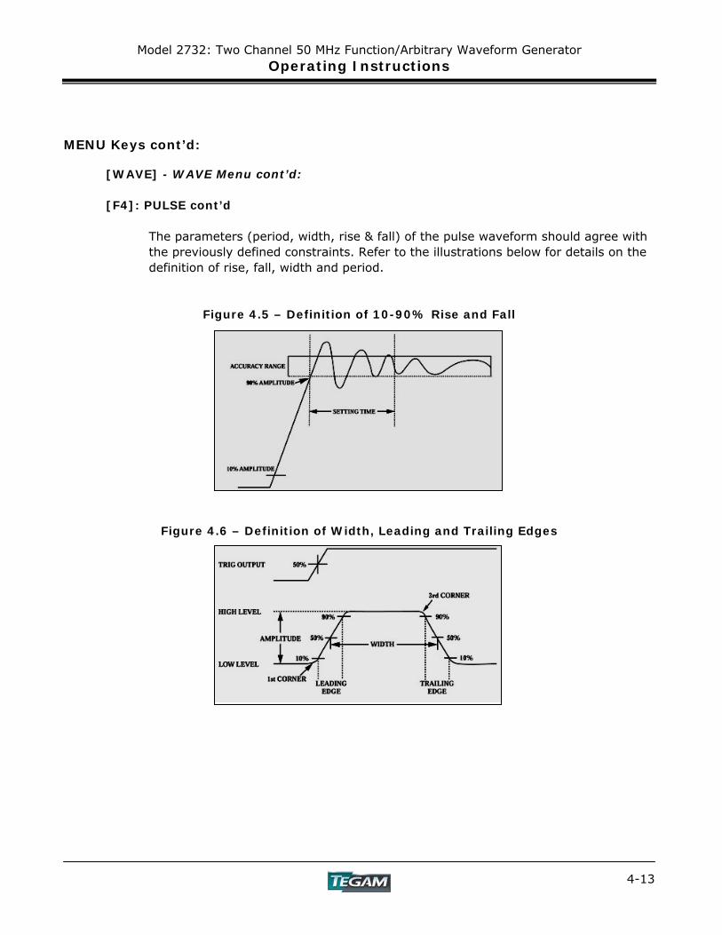
[WAVE] - WAVE Menu cont’d: [F4]: PULSE cont’d
The parameters (period, width, rise & fall) of the pulse waveform should agree with the previously defined constraints. Refer to the illustrations below for details on the definition of rise, fall, width and period.
Figure 4.5 – Definition of 10-90% Rise and Fall
Figure 4.6 – Definition of Width, Leading and Trailing Edges

Model 2732: Two Channel 50 MHz Function/Arbitrary Waveform Generator Operating Instructions
4-14
MENU Keys cont’d: [WAVE] - WAVE Menu cont’d: [F4]: PULSE cont’d [F1]:FREQ/PERIOD
Allows the frequency or the period of the pulse waveform to be defined. The pulse frequency ranges from 500 μHz to 25 MHz (2000 S to 40 nS). The frequency/period limits may be restricted by the width, lead, and trail settings. If the frequency is set then the period is automatically adjusted to 1/f. If the period is set then the frequency is automatically adjusted to 1/P.
[F2]:WIDTH This sets the width of the pulse on time. The minimum allowable
width is 20 nS. (This allows time for a 10 nS lead and trail edge time). The maximum allowable pulse width is 1999 S.
[F3]:EQUAL/EDGE Sets both the leading and trailing edge of the pulse to this transition
time. [F4]:LEAD/TRAIL This allows the leading and trailing edge of the pulse to be
programmed with different values. [F5]:PREV Returns to the previous menu. An example for defining and creating a pulse is at the end of the Operating Instructions section.
Model 2732: Two Channel 50 MHz Function/Arbitrary Waveform Generator Operating Instructions
4-15
MENU Keys cont’d:
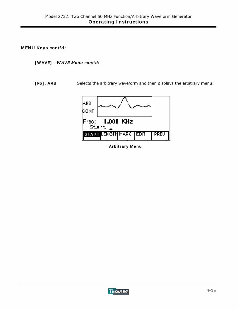
[WAVE] - WAVE Menu cont’d: [F5]: ARB Selects the arbitrary waveform and then displays the arbitrary menu:
Arbitrary Menu
Model 2732: Two Channel 50 MHz Function/Arbitrary Waveform Generator Operating Instructions
4-16
MENU Keys cont’d:
[WAVE] - WAVE Menu cont’d: Arbitrary Waveform Menu: [F1]: START Start Location - Selects the arbitrary waveform start address.
Minimum value =1. The start address must have an odd value. [F2]: LENGTH Waveform Length - Selects the arbitrary waveform length. Use the
START and LENGTH keys to mark a selection of waveform memory that will be executed. The length must have an even value.
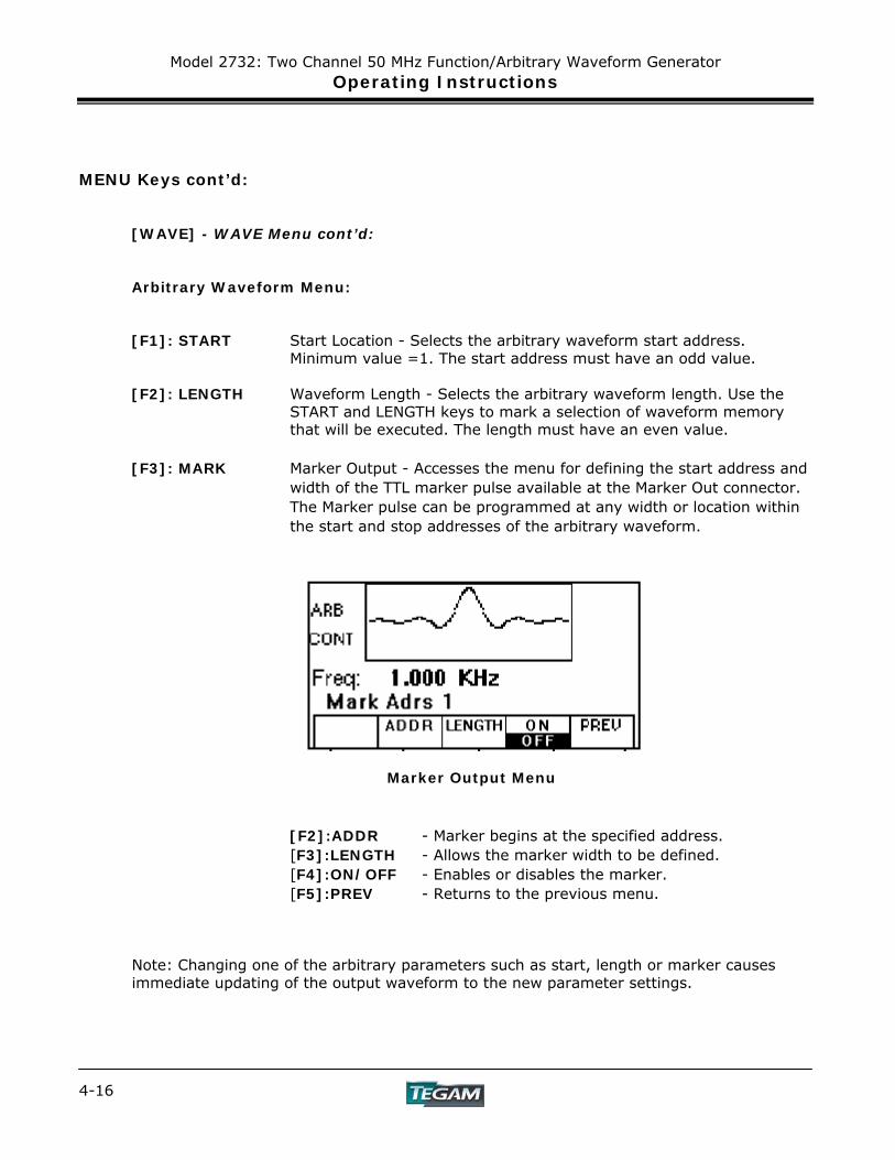
[F3]: MARK Marker Output - Accesses the menu for defining the start address and
width of the TTL marker pulse available at the Marker Out connector. The Marker pulse can be programmed at any width or location within the start and stop addresses of the arbitrary waveform.
Marker Output Menu
[F2]:ADDR - Marker begins at the specified address. [F3]:LENGTH - Allows the marker width to be defined. [F4]:ON/OFF - Enables or disables the marker. [F5]:PREV - Returns to the previous menu.
Note: Changing one of the arbitrary parameters such as start, length or marker causes immediate updating of the output waveform to the new parameter settings.
Model 2732: Two Channel 50 MHz Function/Arbitrary Waveform Generator Operating Instructions
4-17
MENU Keys cont’d:
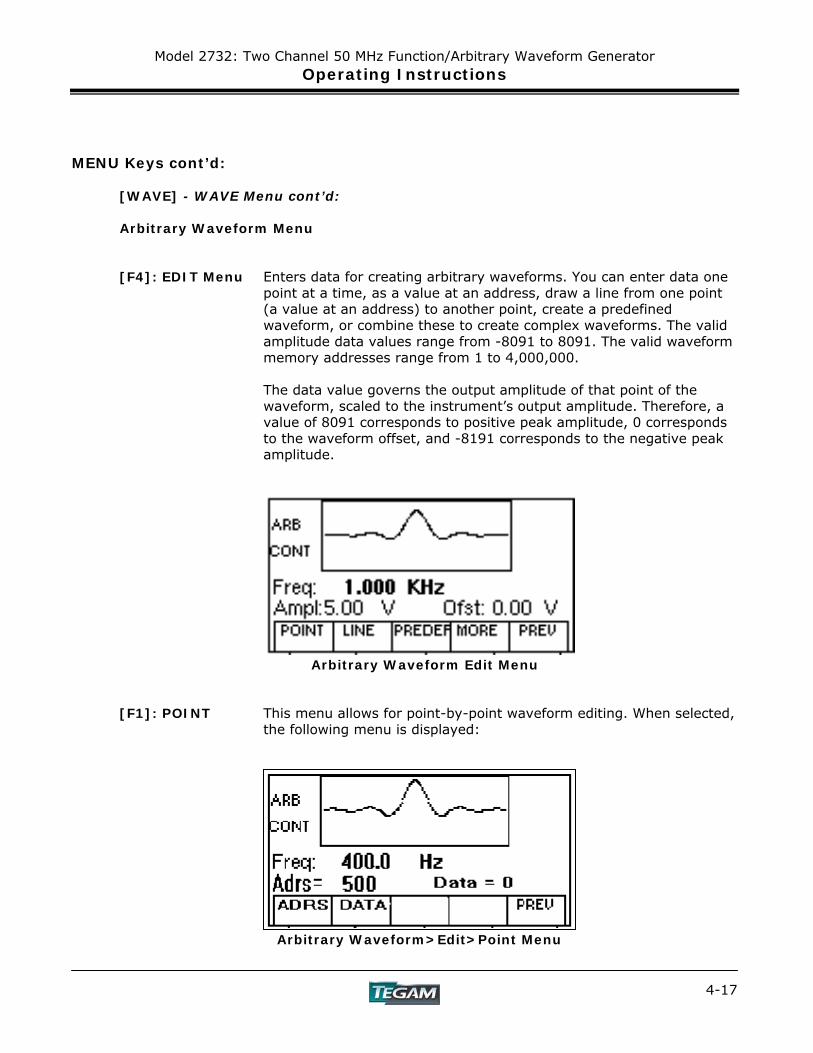
[WAVE] - WAVE Menu cont’d: Arbitrary Waveform Menu [F4]: EDIT Menu Enters data for creating arbitrary waveforms. You can enter data one
point at a time, as a value at an address, draw a line from one point (a value at an address) to another point, create a predefined waveform, or combine these to create complex waveforms. The valid amplitude data values range from -8091 to 8091. The valid waveform memory addresses range from 1 to 4,000,000.
The data value governs the output amplitude of that point of the
waveform, scaled to the instrument’s output amplitude. Therefore, a value of 8091 corresponds to positive peak amplitude, 0 corresponds to the waveform offset, and -8191 corresponds to the negative peak amplitude.
Arbitrary Waveform Edit Menu [F1]: POINT This menu allows for point-by-point waveform editing. When selected,
the following menu is displayed: Arbitrary Waveform>Edit>Point Menu
Model 2732: Two Channel 50 MHz Function/Arbitrary Waveform Generator Operating Instructions
4-18
MENU Keys cont’d:
[WAVE] - WAVE Menu cont’d:
Arbitrary Waveform Edit Menu
[F1]:ADDR - Selects the current address in the arbitrary waveform memory.
[F2]:DATA - Selects the data point value at the current address from –8191 to 8191.
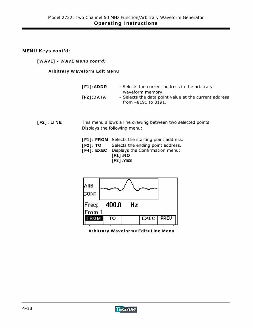
[F2]: LINE This menu allows a line drawing between two selected points.
Displays the following menu: [F1]: FROM Selects the starting point address. [F2]: TO Selects the ending point address. [F4]: EXEC Displays the Confirmation menu: [F1]:NO [F3]:YES
Arbitrary Waveform>Edit>Line Menu

Model 2732: Two Channel 50 MHz Function/Arbitrary Waveform Generator Operating Instructions
4-19
MENU Keys cont’d: [WAVE] - WAVE Menu cont’d: Arbitrary Waveform Edit Menu [F3]: PREDEF Selects one of the predefined waveforms: Sine, Triangle, Square,
Noise, Ramp Up, Ramp Down, Sin(x)/x, Exponent Up, Exponent Down, and Gaussian.
Displays the predefined waveforms menu: Arbitrary Waveform>Edit>Predefined Waveform Menu [F1]: TYPE Selects a Sine, Triangle, Square, Noise, Ramp Up, Ramp Down,
Sin(x)/x, Exponent Up, Exponent Down, or Gaussian waveform. If the Noise function is selected (by pressing [EXEC]), a submenu is displayed. See [F4]:EXEC for more details.
[F1]: ADD - Allows the noise to be added to existing waveform data.
[F3]: NEW - Generate noise waveform/data to be used as a new waveform.
[F4]: EXEC - Execute the wave generation. [F5]: PREV - Return to the previous menu.
[F2]: FROM DATA Selects the starting point of the generated waveform and data value.
Model 2732: Two Channel 50 MHz Function/Arbitrary Waveform Generator Operating Instructions
4-20
MENU Keys cont’d: [WAVE] - WAVE Menu cont’d: Arbitrary Waveform Edit Menu
[F3]: LENG Selects the length of the predefined waveform (number of points for a
full wave). Different waveforms have different limitations on length, as shown in Table 4-3. The maximum allowable length for a predefined waveform is 65,536 points.
Table 4-3: Length Limits for Predefined Waveforms
Wave Minimum length Divisible by Sine 16 4 Triangle 16 4 Square 2 2 Noise 16 1
[F4]: SCALE
Selects the scale factor of the waveform. 100% means that the waveform spans the full scale of -8191 to 8191. Scale factors are limited by the point data value of the starting point and automatically calculated by the unit.
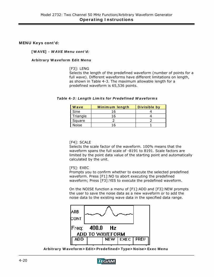
[F5]: EXEC Prompts you to confirm whether to execute the selected predefined
waveform. Press [F1]:NO to abort executing the predefined waveform; Press [F3]:YES to execute the predefined waveform.
On the NOISE function a menu of [F1]:ADD and [F3]:NEW prompts
the user to save the noise data as a new waveform or to add the noise data to the existing wave data in the specified data range.
Arbitrary Waveform>Edit>Predefined>Type>Noise>Exec Menu
Model 2732: Two Channel 50 MHz Function/Arbitrary Waveform Generator Operating Instructions
4-21
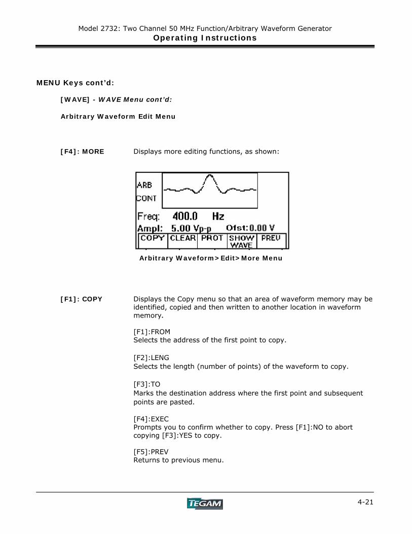
MENU Keys cont’d: [WAVE] - WAVE Menu cont’d: Arbitrary Waveform Edit Menu [F4]: MORE Displays more editing functions, as shown:
Arbitrary Waveform>Edit>More Menu
[F1]: COPY Displays the Copy menu so that an area of waveform memory may be
identified, copied and then written to another location in waveform memory.
[F1]:FROM Selects the address of the first point to copy. [F2]:LENG Selects the length (number of points) of the waveform to copy. [F3]:TO Marks the destination address where the first point and subsequent
points are pasted. [F4]:EXEC Prompts you to confirm whether to copy. Press [F1]:NO to abort
copying [F3]:YES to copy. [F5]:PREV Returns to previous menu.
Model 2732: Two Channel 50 MHz Function/Arbitrary Waveform Generator Operating Instructions
4-22
MENU Keys cont’d: [WAVE] - WAVE Menu cont’d:
Arbitrary Waveform Edit Menu
[F2]: CLEAR Displays the Clear menu so that either a section of or all of waveform memory may be reset to zero data values.
[F1]:FROM Selects the address of the first point to clear. [F2]:TO Selects the address of the last point to clear. [F3]:ALL Clears the whole waveform memory. Equivalent to selecting from 1 to 4,000,000. [F4]:EXEC Prompts you to confirm whether to clear. Press [F1]:NO to abort
clearing, and [F3]:YES to clear the specified range of data. [F5]:PREV Returns to previous menu. [F3]: PROT Displays the Protect menu so that a section of waveform memory may
be protected and made into ROM. [F1]:FROM Selects the starting address of the data to protect. [F2]:TO Selects the ending address of the data to protect. [F3]:ALL Protects the whole waveform memory. Equivalent to selecting from 1 to 4,000,000. NOTE: you can protect only one segment of waveform memory at a
time. [F4]: ON/OFF Enables or disables memory protection. [F5]:PREV Returns to previous menu.
Model 2732: Two Channel 50 MHz Function/Arbitrary Waveform Generator Operating Instructions
4-23
MENU Keys cont’d: [WAVE] - WAVE Menu cont’d:
Arbitrary Waveform Edit Menu [F4]:SHOW WAVE Uses the entire LCD area to graphically display the active waveform.
Pressing the [F4]:SHOW WAVE again or any other key will return the LCD to its normal state.
[F5]:PREV Returns to previous menu.
Model 2732: Two Channel 50 MHz Function/Arbitrary Waveform Generator Operating Instructions
4-24
MENU Keys cont’d:
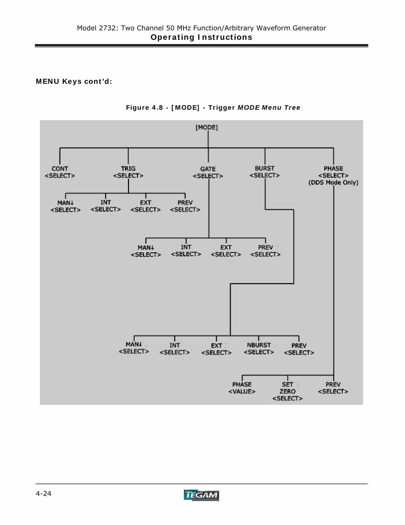
Figure 4.8 - [MODE] - Trigger MODE Menu Tree
Model 2732: Two Channel 50 MHz Function/Arbitrary Waveform Generator Operating Instructions
4-25
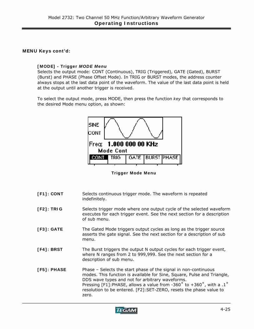
MENU Keys cont’d: [MODE] - Trigger MODE Menu Selects the output mode: CONT (Continuous), TRIG (Triggered), GATE (Gated), BURST (Burst) and PHASE (Phase Offset Mode). In TRIG or BURST modes, the address counter always stops at the last data point of the waveform. The value of the last data point is held at the output until another trigger is received. To select the output mode, press MODE, then press the function key that corresponds to the desired Mode menu option, as shown:
Trigger Mode Menu
[F1]: CONT Selects continuous trigger mode. The waveform is repeated
indefinitely. [F2]: TRIG Selects trigger mode where one output cycle of the selected waveform
executes for each trigger event. See the next section for a description of sub menu.
[F3]: GATE The Gated Mode triggers output cycles as long as the trigger source
asserts the gate signal. See the next section for a description of sub menu.
[F4]: BRST The Burst triggers the output N output cycles for each trigger event,
where N ranges from 2 to 999,999. See the next section for a description of sub menu.
[F5]: PHASE Phase – Selects the start phase of the signal in non-continuous
modes. This function is available for Sine, Square, Pulse and Triangle, DDS wave types and not for arbitrary waveforms. Pressing [F1]:PHASE, allows a value from -360˚ to +360˚, with a .1˚ resolution to be entered. [F2]:SET-ZERO, resets the phase value to zero.
Model 2732: Two Channel 50 MHz Function/Arbitrary Waveform Generator Operating Instructions
4-26
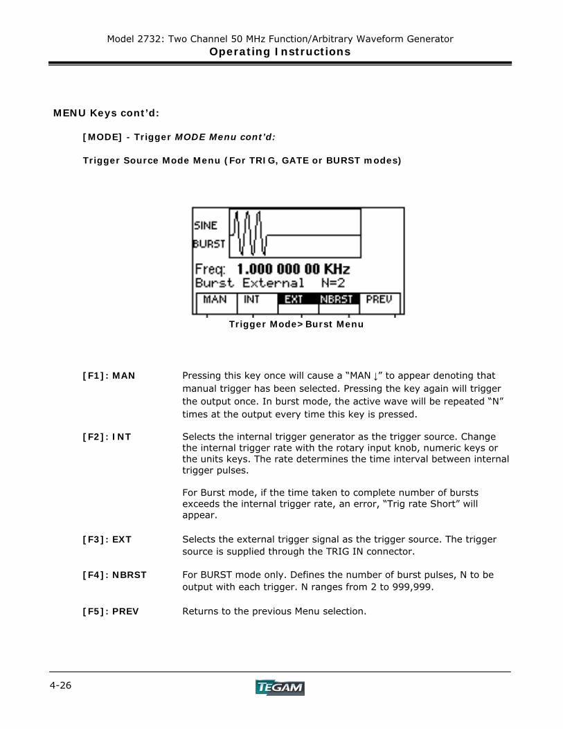
MENU Keys cont’d: [MODE] - Trigger MODE Menu cont’d: Trigger Source Mode Menu (For TRIG, GATE or BURST modes)
Trigger Mode>Burst Menu [F1]: MAN Pressing this key once will cause a “MAN ↓” to appear denoting that
manual trigger has been selected. Pressing the key again will trigger the output once. In burst mode, the active wave will be repeated “N” times at the output every time this key is pressed.
[F2]: INT Selects the internal trigger generator as the trigger source. Change
the internal trigger rate with the rotary input knob, numeric keys or the units keys. The rate determines the time interval between internal trigger pulses.
For Burst mode, if the time taken to complete number of bursts
exceeds the internal trigger rate, an error, “Trig rate Short” will appear.
[F3]: EXT Selects the external trigger signal as the trigger source. The trigger
source is supplied through the TRIG IN connector. [F4]: NBRST For BURST mode only. Defines the number of burst pulses, N to be
output with each trigger. N ranges from 2 to 999,999. [F5]: PREV Returns to the previous Menu selection.

Model 2732: Two Channel 50 MHz Function/Arbitrary Waveform Generator Operating Instructions
4-27
MENU Keys cont’d: [SWEEP] - SWEEP Menu
Figure 4.9 - [SWEEP] - SWEEP Menu Tree
[SWEEP] - SWEEP Menu The sweep function applies only to standard waveforms and is not used for arbitrary waveforms. Pressing the [SWEEP] key, selects the Sweep Mode and allows the sweep parameters to be entered. These are as Start, Stop, Rate and either linear or logarithmic sweep rates. To select the sweep mode, press SWEEP, then press the function key that corresponds to the desired Sweep menu option, as shown:
Sweep Menu
Model 2732: Two Channel 50 MHz Function/Arbitrary Waveform Generator Operating Instructions
4-28
MENU Keys cont’d: [SWEEP] - SWEEP Menu cont’d:
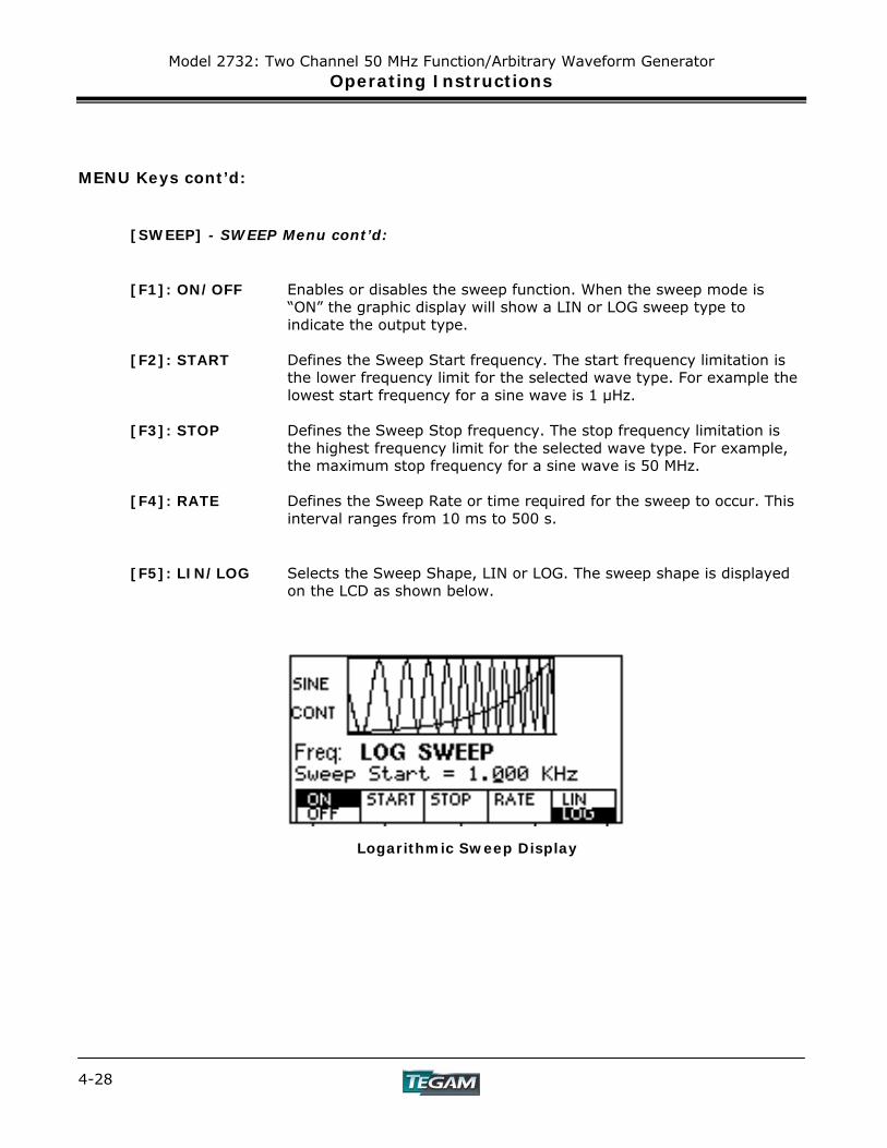
[F1]: ON/OFF Enables or disables the sweep function. When the sweep mode is
“ON” the graphic display will show a LIN or LOG sweep type to indicate the output type.
[F2]: START Defines the Sweep Start frequency. The start frequency limitation is
the lower frequency limit for the selected wave type. For example the lowest start frequency for a sine wave is 1 μHz.
[F3]: STOP Defines the Sweep Stop frequency. The stop frequency limitation is
the highest frequency limit for the selected wave type. For example, the maximum stop frequency for a sine wave is 50 MHz.
[F4]: RATE Defines the Sweep Rate or time required for the sweep to occur. This
interval ranges from 10 ms to 500 s.
[F5]: LIN/LOG Selects the Sweep Shape, LIN or LOG. The sweep shape is displayed
on the LCD as shown below.
Logarithmic Sweep Display
Model 2732: Two Channel 50 MHz Function/Arbitrary Waveform Generator Operating Instructions
4-29
MENU Keys cont’d: [MODUL] – MODULATION Menu
Figure 4.10 - [MODUL] – MODULATION Menu Tree
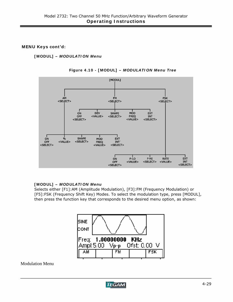
[MODUL] – MODULATION Menu
Selects either [F1]:AM (Amplitude Modulation), [F3]:FM (Frequency Modulation) or [F5]:FSK (Frequency Shift Key) Modes. To select the modulation type, press [MODUL], then press the function key that corresponds to the desired menu option, as shown:
Modulation Menu
Model 2732: Two Channel 50 MHz Function/Arbitrary Waveform Generator Operating Instructions
4-30
MENU Keys cont’d: [MODUL] – MODULATION Menu cont’d:
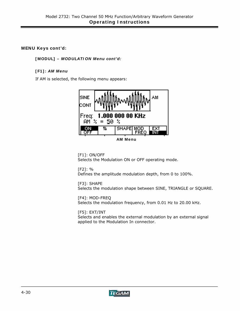
[F1]: AM Menu
If AM is selected, the following menu appears:
AM Menu
[F1]: ON/OFF Selects the Modulation ON or OFF operating mode. [F2]: % Defines the amplitude modulation depth, from 0 to 100%.
[F3]: SHAPE Selects the modulation shape between SINE, TRIANGLE or SQUARE. [F4]: MOD-FREQ Selects the modulation frequency, from 0.01 Hz to 20.00 kHz. [F5]: EXT/INT Selects and enables the external modulation by an external signal applied to the Modulation In connector.
Model 2732: Two Channel 50 MHz Function/Arbitrary Waveform Generator Operating Instructions
4-31
MENU Keys cont’d:
[MODUL] – MODULATION Menu cont’d:
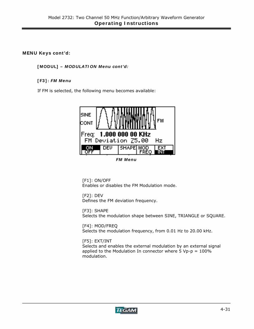
[F3]: FM Menu If FM is selected, the following menu becomes available:
FM Menu
[F1]: ON/OFF Enables or disables the FM Modulation mode. [F2]: DEV Defines the FM deviation frequency. [F3]: SHAPE Selects the modulation shape between SINE, TRIANGLE or SQUARE. [F4]: MOD/FREQ Selects the modulation frequency, from 0.01 Hz to 20.00 kHz. [F5]: EXT/INT Selects and enables the external modulation by an external signal applied to the Modulation In connector where 5 Vp-p = 100% modulation.
Model 2732: Two Channel 50 MHz Function/Arbitrary Waveform Generator Operating Instructions
4-32
MENU Keys cont’d:
[MODUL] – MODULATION Menu cont’d:
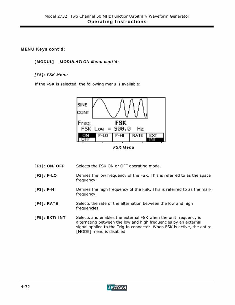
[F5]: FSK Menu If the FSK is selected, the following menu is available:
FSK Menu
[F1]: ON/OFF Selects the FSK ON or OFF operating mode. [F2]: F-LO Defines the low frequency of the FSK. This is referred to as the space
frequency. [F3]: F-HI Defines the high frequency of the FSK. This is referred to as the mark
frequency. [F4]: RATE Selects the rate of the alternation between the low and high
frequencies. [F5]: EXT/INT Selects and enables the external FSK when the unit frequency is
alternating between the low and high frequencies by an external signal applied to the Trig In connector. When FSK is active, the entire [MODE] menu is disabled.
Model 2732: Two Channel 50 MHz Function/Arbitrary Waveform Generator Operating Instructions
4-33
MENU Keys cont’d:
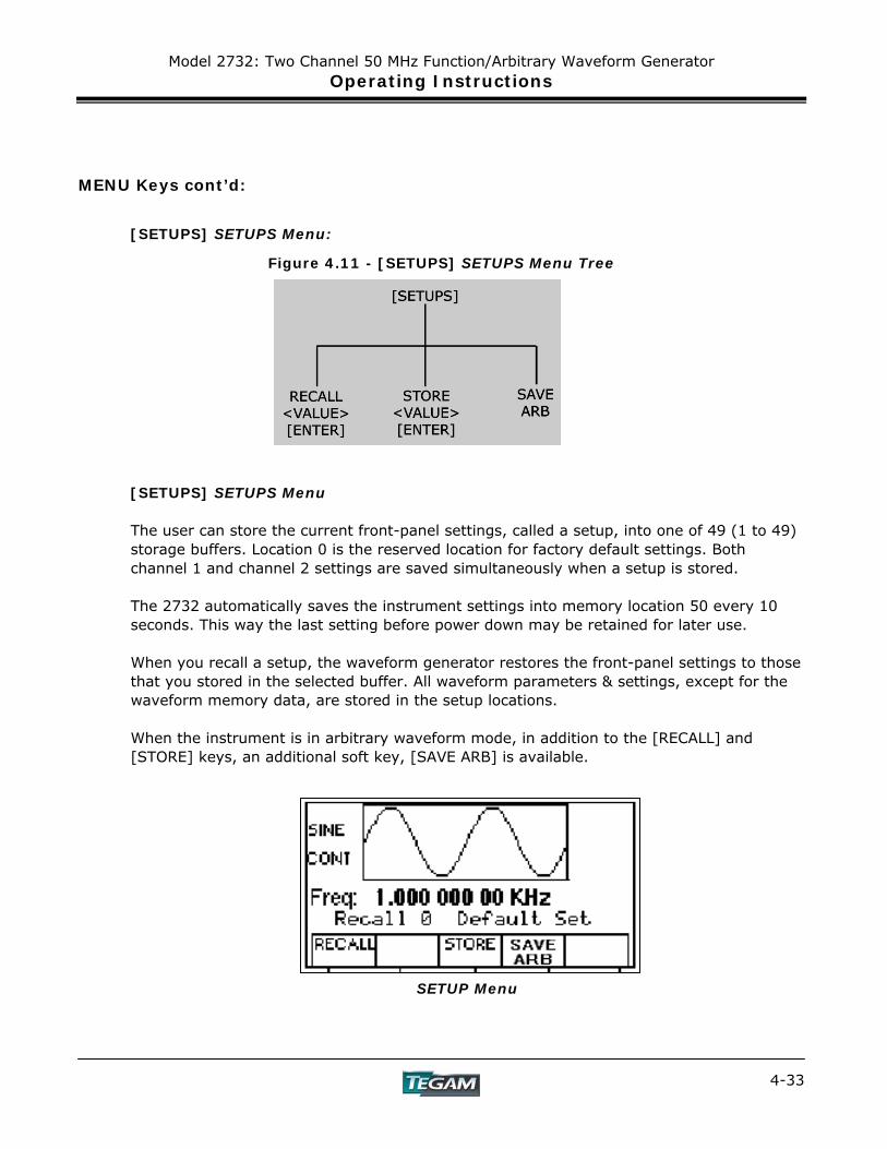
[SETUPS] SETUPS Menu:
Figure 4.11 - [SETUPS] SETUPS Menu Tree
[SETUPS] SETUPS Menu The user can store the current front-panel settings, called a setup, into one of 49 (1 to 49) storage buffers. Location 0 is the reserved location for factory default settings. Both channel 1 and channel 2 settings are saved simultaneously when a setup is stored. The 2732 automatically saves the instrument settings into memory location 50 every 10 seconds. This way the last setting before power down may be retained for later use. When you recall a setup, the waveform generator restores the front-panel settings to those that you stored in the selected buffer. All waveform parameters & settings, except for the waveform memory data, are stored in the setup locations. When the instrument is in arbitrary waveform mode, in addition to the [RECALL] and [STORE] keys, an additional soft key, [SAVE ARB] is available.
SETUP Menu
Model 2732: Two Channel 50 MHz Function/Arbitrary Waveform Generator Operating Instructions
4-34
MENU Keys cont’d:
[SETUPS] SETUPS Menu cont’d: [F1]: RECALL Recalls a previously stored front-panel setup from the selected buffer.
A recall restores settings for both channels. Change the buffer number by using the rotary input knob. Valid storage buffer numbers are from 1 to 49. Buffer 0 is the factory default setup location. Buffer 50 will restore the last saved settings. To recall a setting, press: [RECALL]>[MEMORY LOCATION 0-49]>[ENTER]
[F3]: STORE Stores the current front-panel setup to the specified storage location.
Change the location number by using the data keys or the rotary input knob. Valid storage buffer numbers range from 1 to 49. Press the [ENTER] key to store the settings. A “DONE” message will appear to confirm that the current settings have been saved. To store a setting, press: [STORE]>[MEMORY LOCATION 1-49]>[ENTER]
[F4]: SAVE ARB Pressing this soft key will write the arbitrary waveform memory into FLASH (non-volatile) memory. The key is visible only when the 2732 is in the ARB waveform mode.
For example, custom wave data downloaded from WaveWorks DDS to the 2732 can be written into FLASH memory by depressing the [F4]: SAVE ARB button. This way it is retained in the event that power is lost.
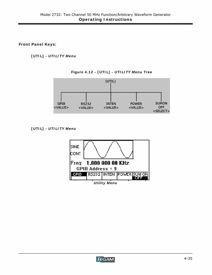
Model 2732: Two Channel 50 MHz Function/Arbitrary Waveform Generator Operating Instructions
4-35
Front Panel Keys:
[UTIL] - UTILITY Menu
Figure 4.12 - [UTIL] - UTILITY Menu Tree
[UTIL] - UTILITY Menu
Utility Menu
Model 2732: Two Channel 50 MHz Function/Arbitrary Waveform Generator Operating Instructions
4-36
Front Panel Keys cont’d:
[UTIL] - UTILITY Menu cont’d: [F1]: GPIB Selects the GPIB mode of operation. After selection, the GPIB address
can be set to any value from 1 to 31 using the rotary knob or data entry keys. Press the [ENTER] key to set the address value. The value is kept in a nonvolatile memory and is retained. The factory default address is 9. Setting the address to 31 puts the device in the off-bus state (it will not respond to messages on the GPIB bus).
[F2]: RS232 Selects the RS-232 remote control mode. After selection, the baud
rate can be selected as 1200, 2400, 9600, 19200, 38400, 57600 or 115k. The RS-232C interface is always set to 8 data bits, 1 stop bit, and no parity.
[F3]: INTEN (Intensity) Selects the intensity of the LCD display. Select a value
using the numerical data keys or rotary knob. Valid numeric values are from 1 to 31. The current value is stored in nonvolatile memory, after a 20 second time-out.
[F4]: POWER (Power-on default) Selects the power-on default setting. Select a
value using the data keys or the rotary knob. The selection is effective after a 20 s time-out period. Select zero (0) to have the waveform generator power on with the factory default settings. Select 50 to have the waveform generator power-on with the settings it had at the last power-off. Instrument settings are automatically stored into location 50 every 10 seconds. Location 50 retains these values so that upon power up, the last instrument settings before power down are recalled. Location 50 is not user-definable.
Select any other value in the range from 1 to 49 to have the
waveform generator power-on with the settings that you have saved with SETUPS STORE in the range 1 to 49.
Model 2732: Two Channel 50 MHz Function/Arbitrary Waveform Generator Operating Instructions
4-37
Front Panel Keys cont’d:
[ON] - ON Key Use this key to control the main output signal from channel 1 or 2. When the output is active, “Ch1 On”” or “Ch 2 On” is displayed depending on the output selected. This message appears in the upper right-hand side of the LCD. [◄] [►] - Cursor Movement Keys Use these keys to move the cursor (when visible) either left or right. They are used in conjunction with the rotary input knob to set parameter values. Rotary Input Knob Use this knob to increase and decrease numeric values or to scroll through a list. The cursor indicates the low-order position of the displayed value, which changes when you rotate the knob (for straight numeric entries only). For other types of data, the whole value changes when you rotate the knob. [ENTER] – ENTER Key Pressing the [ENTER] key will activate a menu selection or numerical value. If the OUTPUT is enabled, then the change will take place immediately at the output. The exception is if an illegal command is received. This will produce an “Out of Range” or other error message to appear and no changes will take place at the output. If a parametric value is typed and the [ENTER] key is pressed instead of a units key, the instrument will default to the previous units of measure. When defining arbitrary values such as marker and data locations, lengths and other soft key functions, the [ENTER] key must be pressed to activate the new value. Otherwise the data will be lost and the previous value of that parameter will be retained. When a numerical value is being entered, the cursor will lead the position of the active digit. Pressing the [ENTER] key will return the cursor to the far left position and will add zeros to complete a numeric value. This change visually confirms new parameter activation. To enable soft key selections such as modulation or sweep ON/OFF, pressing the [ENTER] key is not required. The instrument’s status is shown on the display. UNITS Keys When defining numerical values as in frequency, time or amplitude, the units keys (located in the far right side of the keypad) serve multiple functionalities. They specify the units (frequency, time, or amplitude) for the parameter being defined. In addition, pressing a units key will automatically activate the new parametric value. If the output is enabled, the new value will be produced at the output. The units key is an alternative to pressing the [ENTER] key when setting numeric values for wave parameters.

Model 2732: Two Channel 50 MHz Function/Arbitrary Waveform Generator Operating Instructions
4-38
Power-On Settings At power-on, the waveform generator performs a diagnostic self-test procedure to check itself for errors. If it finds an error, an error code and text appear in the display window. Other error codes appear when you enter an invalid front-panel setting. For more information on error codes, see the Error Indication section. When the waveform generator finishes the diagnostic self-test routine, it enters the local state (LOCS) and assumes power-on default settings. Table 3-2 lists the factory default settings. You can program the waveform generator for any settings you want at power on, as described earlier in the [UTIL] section.
Table 4.4 - Power-on Default Settings (Location 0)
Key Function Setting Comments FREQUENCY 1 kHz Wave frequency RATE(ARB) 1 μs Sample time per point AMPLITUDE 5.00 V Peak to peak output amplitude FUNCTION SINE Output waveform OFFSET 0.00 V Zero offset REPETITION 10 mS Internal trigger rate MODE CONT Waveform mode N-BURST 2 Waves per burst START ADRS 1 Start memory address WAVELENGTH 1000 Number of points per waveform TRIG SOURCE EXT External trigger source OUTPUT OFF Output disabled SWEEP OFF Sweep execution MODULATION OFF Modulation execution
Model 2732: Two Channel 50 MHz Function/Arbitrary Waveform Generator Operating Instructions
4-39
Instrument Operation Impedance Matching The waveform generator output circuit operates as a 50 Ω voltage source and is designed for a 50 Ω load. At higher frequencies, unterminated or improperly terminated outputs cause aberrations on the output waveform. In addition, loads less than 50 Ω reduce the waveform amplitude, while loads larger than 50 Ω increase the waveform amplitude. Excessive distortion or aberrations caused by improper termination are less noticeable at lower frequencies, especially with sine and triangle waveforms. To ensure waveform integrity, follow these precautions:
1. Use high quality 50 Ω coaxial cables and connectors. 2. Make all connections tight and keep cable lengths as short as possible. 3. If it is necessary to reduce waveform amplitudes, use good quality attenuators. 4. Use proper termination or impedance matching devices to avoid reflections. 5. Ensure that attenuators and terminations have adequate power handling
capabilities. 6. If there is a DC voltage across the output load, use a coupling capacitor in series
with the load. The time constant of the coupling capacitor and load must be long enough to maintain pulse flatness.
If the waveform generator is driving a high impedance, such as a 1 MΩ input impedance
(paralleled by a stated capacitance) of an oscilloscope’s vertical input, connect the transmission line to a 50 Ω attenuator, a 50 Ω termination and to the oscilloscope input. The attenuator isolates the input capacitance of the device and terminates the waveform generator properly.

Model 2732: Two Channel 50 MHz Function/Arbitrary Waveform Generator Operating Instructions
4-40
Instrument Operation cont’d: Waveform and Execution Memory The waveform generator uses two forms of memory:
• Dynamic RAM for generating arbitrary waveforms. • Non-volatile FLASH for storing arbitrary waveform data and front panel settings
during power off conditions.
Both dynamic RAM and non-volatile flash memories consist of 4,000,000 points at which you can specify a value from -8191 to 8191. You can scale these points through the output amplitude setting; that is, data point 8191 is equal to the positive peak of the user-defined output amplitude.
Each channel contains both types of memory for a system total of 8,000,000 points of memory in the Dynamic RAM and 8,000,000 points total in the standard FLASH.
Dynamic RAM The DRAM is a temporary holding place for waveform data. It is used to either edit or execute wave data. The following operations can be performed in DRAM: - Insert and scale any of the following predefined waveforms: sine triangle square noise - Draw a line between any two points - Clear (set to zero) any set of points or all points - Protect (prevent from changing) any set of points or all points - Copy any set of points to another area - Set individual point values Up to 4,000,000 continuous points of waveform memory per channel can be executed by specifying a starting address in waveform memory and length. After specifying a section of waveform memory for execution, the following parameters can be set: - Point rate (frequency) - Peak-to-peak amplitude (voltage) - Offset (voltage)
Model 2732: Two Channel 50 MHz Function/Arbitrary Waveform Generator Operating Instructions
4-41
Instrument Operation cont’d: Nonvolatile FLASH (Arbitrary Waveform Memory) The FLASH retains arbitrary waveform data in the event of power loss. This memory is a matrix 16,383 x 4,000,000 that you use to plot your arbitrary waveforms. The 2732 contains two channels of identical, independent FLASH memory. The FLASH also stores up to 49 front-panel setups. For more information see the [SETUPS] key section. For arbitrary waveform data, the waveform generator loads the selected contents of the FLASH (arbitrary waveform memory) into the DRAM for execution. In order to save arbitrary edited data into flash memory, the instrument needs to be in arbitrary wave mode. In this mode, when wave data is changed, the instrument displays a message "SAVE DATA" after each modification of the arbitrary waveform in the EDIT menu. Arbitrary wave data may also be saved by pressing the [SETUPS]>[SAVE ARB] keys. If the arbitrary data is not saved then it will be lost upon powering the instrument down. Because it is impossible to guarantee against loss of stored data, you should always maintain a backup of the data stored in memory so that you can manually restore such data, if necessary. This can be achieved by using WaveWorks DDS.
Displaying Errors At power-on, the waveform generator performs a diagnostic routine to check itself for problems. If the diagnostic routine finds an error, an error message is displayed. The waveform generator also displays error messages when front-panel settings are either invalid or may produce unexpected results.
Table 4.5 - Error messages for Model 2732 Message Text Cause Out of range Attempt to set variable out of instrument limits. Setting conflict Can't have this parameter set with some other. Trig rate short Internal trigger rate too short for wave/burst. Empty location Attempt to restore non-existent setting. SCALE too high Attempt to set scale too high for current dot value Protected RAM Attempt to write to protected RAM range. RAM error Error in testing RAM. Save RAM New firmware installed. Must divide by 4 Predefined wavelength must be divisible by 4. Must divide by 2 Predefined wavelength must be divisible by 2.
Model 2732: Two Channel 50 MHz Function/Arbitrary Waveform Generator Operating Instructions
4-42
Instrument Operation cont’d:
Using The Model 2732 This section explains how to generate various waveforms and modify the output waveform including:
Generating a standard waveform from the function generator Defining a Pulse Waveform Creating an Arbitrary Waveform: Loading Individual Data Points Defining a Wave segment for Execution Creating a Complex Arbitrary Waveform: Using Predefined Waves, Line Drawing,
and the Waveform ADD Function Setting the Frequency Generating a Waveform Output Modifying Waveform output Using Voltage Offset Storing and Recalling a Waveform Generator Setup Creating and Downloading a Waveform with WaveWorks DDS software
Model 2732: Two Channel 50 MHz Function/Arbitrary Waveform Generator Operating Instructions
4-43
Instrument Operation cont’d: Generating a Standard Waveform You can select several standard waveforms as: sine, triangle/ramp, square and pulse. Creating a standard waveform requires selecting the waveform type, parameters, modes, etc., and their settings that define the waveform.
Generating a standard waveform requires the following:
Selecting the waveform Setting the output frequency Setting the output amplitude and offset Choosing the output trigger mode Enabling the output
To begin, choose a desired channel by pressing the [CHAN] key. Step 1 - ACTION KEYSTROKES Select the wave type by choosing a waveform [WAVE], then: from the menu [F1],[F2],[F3],[F4],[F5] Step 2 - ACTION KEYSTROKES Set the Output Frequency using the rotary [PARAM] knob or data entry keys Set Frequency Value Step 3 - ACTION KEYSTROKES Set the Output Amplitude & offset by using the [PARAM] rotary knob or numeric keypad to set the [F3]:AMPL amplitude Set Amplitude Value [F3]:OFST Set Offset Value Step 4 - ACTION KEYSTROKES Set the Output Mode by choosing the desired [MODE] function from the MODE menu and enabling the [F1],[F2],[F3],[F4] appropriate output [ON]
Model 2732: Two Channel 50 MHz Function/Arbitrary Waveform Generator Operating Instructions
4-44
Instrument Operation cont’d:
Defining a Pulse Waveform Before attempting to create a pulse waveform, the user should have a clear
understanding of the definitions of the pulse parameters. Refer to Figures 4.5, 4.6, & 4.7 for definitions of lead time, trail time, width, and period.
In addition, the pulse parameters must meet certain constraints. These constraints
are defined by the instrument’s capabilities and logic. A list of these constraints is provided below:
Width < Period Width ≥ Period * 1 E-6 Width ≥ (Lead+Trail) Period > Width + (Rise + Fall) Lead ≥ Width / 100 (or Lead = .01 μs) Trail ≥ Width / 100 (or Trail = .01 μs) Rise > Period / 100,000 (or Rise = .01 µs) Fall > Period / 100,000 (or Fall = .01 µs)
1. The first step is to sketch out a representation of the desired pulse.
Determine the lead, trail, width and frequency/period in terms of the definitions used in this manual. (Figures 4.5, 4.6, & 4.7)
2. Step through each of the above inequalities to make sure that the pulse parameters meet the constraints. The above conditions must be met before you can proceed.
3. In addition, the lead, trail, and width must be set to their minimum values to allow flexibility when setting the pulse width and frequency/period.
a. Set lead & trail to 10 ns. b. Set the width to the minimum allowable value which satisfies the
condition, Width ≥ P * 1E-6. 4. Set the frequency/period to the desired value. 5. Set the width to the desired value. Make sure the width value satisfies
the term, Width ≥ (Lead+Trail). If it does not, then the lead and trail times may need adjusting to satisfy the inequality.
6. Set the lead and trail times to the required values. Make sure they satisfy the terms, Lead ≥ Width / 100 (or Lead = .01 μs) & Trail ≥ Width / 100 (or Trail = .01 μs).
If during parameter definition, an “Out of Range” message appears on the LCD, it is necessary to adjust the dependent parameters so that new parameters may be entered.
Model 2732: Two Channel 50 MHz Function/Arbitrary Waveform Generator Operating Instructions
4-45
Instrument Operation cont’d: Creating an Arbitrary Waveform You can create an arbitrary waveform using the following methods:
Entering individual data points Drawing lines between data points Creating a predefined waveform Combining any of these methods
NOTE: You can use a software package such as WaveWorks DDS to create, edit and upload/download Arbitrary Waveforms. WaveWorks DDS also has the ability to import waveform data in *.txt format. WaveWorks DDS is included at no additional charge with the purchase of any TEGAM 2720, 2725, 2730, and 2732. For more information on additional waveform software solutions, contact your local TEGAM sales office. There is no need to use all 4,000,000 data points /channel for one waveform. You can program any number of waveforms into waveform memory, keeping in mind the addresses where one waveform ends and the other begins. Data to be executed may be specified by defining the starting point and data length. Data to be executed may overlap into more than one wave segment. This makes it possible to execute any predefined segment of waveform data contained within in RAM. The waveform's frequency and amplitude are influenced by the number of data points and their bit value. For further information on how the number of data points and their bit count influences the frequency and amplitude of a waveform, refer to the “Setting the Frequency” and “Setting the Amplitude” sections, respectively.
Example Text File Model 2732 129 257 384 509 633 etc….
Model 2732: Two Channel 50 MHz Function/Arbitrary Waveform Generator Operating Instructions
4-46
Examples: Creating an Arbitrary Waveform: Loading Individual Data Points
The most basic way to program an arbitrary waveform is to enter data points for the waveform, one data point at a time. While this can become tedious the auto-increment function helps this process. To enter individual data points into waveform memory, follow these steps: Specify a channel using the [CHAN] key.
1. Press [WAVE] to display the waveform selection menu. 2. Press [F5]:ARB to display the arbitrary menu. 3. Press [F4]:EDIT to display the Edit menu. 4. Press [F1]:POINT, to select the point-by-point programming mode. 5. Press [F1]:ADDRESS 6. Use the rotary knob or the numerical keys to enter the address. 7. Press [F2]:DATA. 8. Use the rotary knob or the numerical keys to enter the value for the data
point. Valid entries range from –8191 to 8191. 9. Repeat steps 5 through 9 until you finish programming your arbitrary
waveform.
NOTE: Each time you press ENTER to complete a data point entry in numerical mode, the
auto-increment address advances the "A= value" by one.
Model 2732: Two Channel 50 MHz Function/Arbitrary Waveform Generator Operating Instructions
4-47
Examples cont’d: Defining a Wave Segment for Execution To specify waveform data stored in dynamic RAM for execution, specify its starting address and length in the [F5]:ARB menu.
1. Select either channel 1 or 2 to ON using the [CHAN] key. 2. Press [WAVE] and select the [F5]:ARB function. 3. Press [F1]:START to set the address. Valid entries range from 1 to
3,999,999. Press [ENTER] to activate the start value. 4. Press [F2]:LENGTH to display the length of the waveform. Valid
entries range from 2 to 4,000,000.
Use the rotary input knob or the numerical keys to enter the length of the waveform. The example below will demonstrate how to specify the memory locations in RAM for execution. ACTION KEYSTROKES Instruct the 2732 to execute the first 1000 [WAVE] points of waveform data in RAM. [F5]:ARB [F1]:START [1], [ENTER] [F2]:LENGTH [1][0][0][0], [ENTER] [F5]:PREV [MODE] [F1]:CONT OUTPUT ON
Model 2732: Two Channel 50 MHz Function/Arbitrary Waveform Generator Operating Instructions
4-48
Examples cont’d:
Creating a Complex Arbitrary Waveform: Using Predefined Waves, Line Drawing, and the Waveform ADD Function To create a complex arbitrary waveform:
Load a predefined sine waveform into arbitrary waveform memory Load a scaled sine wave at the positive peak of the first sine wave Draw a straight line between two data points in the waveform Add a pulse/glitch to the waveform Add a noise signal at the negative peak of the first sine wave
To see the waveform as you build it, connect the waveform generator to an oscilloscope and perform the following steps: The following steps set up the waveform shown in Figure 4.2. Step 1 - ACTION KEYSTROKES Make sure that arb memory locations, 1 to 1000 are not protected. To access the protection menu, press [WAVE]>[ARB]>[EDIT]>[MORE]>[PROT] and verify that [OFF] is selected. Load a 1000-point, 50% scaled, [WAVE] predefined sine wave into waveform [F5]:ARB memory starting at address 1 [START] [1], [ENTER] [LENGTH] [1][0][0][0], [ENTER] [F4]:EDIT [F3]:PREDEF [F1]:TYPE (rotate knob for selection) SINE, [ENTER] [F2]:FROM/DATA [1], [ENTER] [F3]:LENG [1][0][0][0], [ENTER] [F4]:SCALE [5][0], [ENTER] [F5]:EXEC [F3]:YES
Model 2732: Two Channel 50 MHz Function/Arbitrary Waveform Generator Operating Instructions
4-49
Examples cont’d: Step 2 - ACTION KEYSTROKES When the [WAVE] key is pressed you will be prompted to save the data in flash memory so that the data can be retained during power down. Select [F3]:YES. Load a 5% scaled, 100 point [WAVE] predefined waveform into waveform [F5]:ARB memory starting at address 200. [F4]:EDIT [F3]:PREDEF [F1]:TYPE SINE [F2]:FROM [2][0][0], [ENTER] [F3]:LENG [1][0][0], [ENTER] [F4]:SCALE [0][5], [ENTER] [F5]:EXEC [F3]:YES You should have a 2.5 Vp-p, 1 kHz sine wave on your oscilloscope. The sine wave should have a .25 Vp-p sine wave attached to it at data locations 200 to 300 (at the positive peak). Step 3 - ACTION KEYSTROKES Draw a line between address 251 [WAVE] (the highest point of the sine wave) and [F5]:ARB address 501 (where the sine wave crosses [F4]:EDIT the origin). [F2]:LINE [F1]:FROM [2][5][1], [ENTER] [F2]:TO [5][0][1], [ENTER] [F4]:EXEC
[F3]:YES
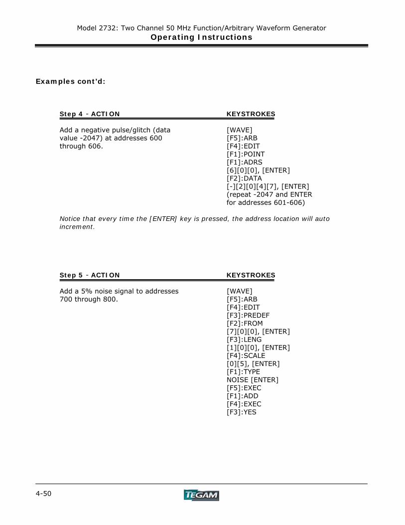
Model 2732: Two Channel 50 MHz Function/Arbitrary Waveform Generator Operating Instructions
4-50
Examples cont’d: Step 4 - ACTION KEYSTROKES Add a negative pulse/glitch (data [WAVE] value -2047) at addresses 600 [F5]:ARB through 606. [F4]:EDIT [F1]:POINT [F1]:ADRS [6][0][0], [ENTER] [F2]:DATA [-][2][0][4][7], [ENTER] (repeat -2047 and ENTER for addresses 601-606) Notice that every time the [ENTER] key is pressed, the address location will auto increment.
Step 5 - ACTION KEYSTROKES Add a 5% noise signal to addresses [WAVE] 700 through 800. [F5]:ARB [F4]:EDIT [F3]:PREDEF [F2]:FROM [7][0][0], [ENTER] [F3]:LENG [1][0][0], [ENTER] [F4]:SCALE [0][5], [ENTER] [F1]:TYPE NOISE [ENTER] [F5]:EXEC [F1]:ADD [F4]:EXEC [F3]:YES

Model 2732: Two Channel 50 MHz Function/Arbitrary Waveform Generator Operating Instructions
4-51
Examples cont’d:
Figure 4.13: Sine Wave with Superimposed Noise and Glitches
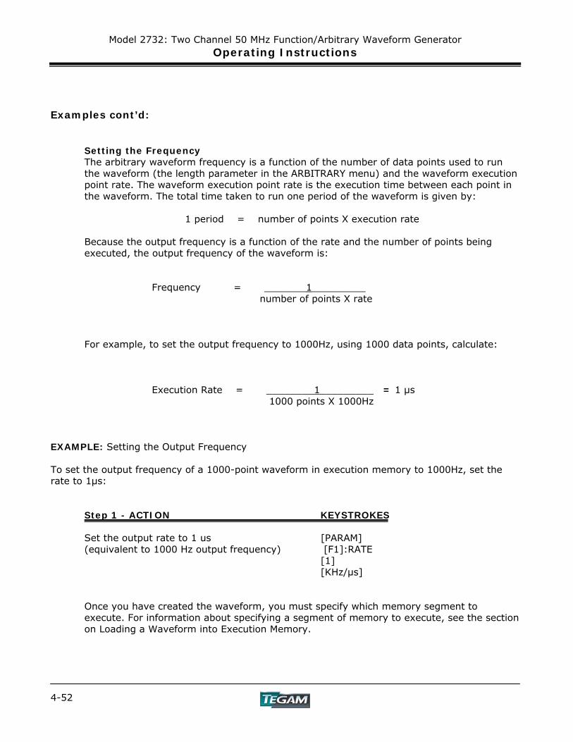
Model 2732: Two Channel 50 MHz Function/Arbitrary Waveform Generator Operating Instructions
4-52
Examples cont’d: Setting the Frequency The arbitrary waveform frequency is a function of the number of data points used to run the waveform (the length parameter in the ARBITRARY menu) and the waveform execution point rate. The waveform execution point rate is the execution time between each point in the waveform. The total time taken to run one period of the waveform is given by:
1 period = number of points X execution rate
Because the output frequency is a function of the rate and the number of points being executed, the output frequency of the waveform is: Frequency = _______1_________
number of points X rate
For example, to set the output frequency to 1000Hz, using 1000 data points, calculate: Execution Rate = ________1_________ = 1 μs 1000 points X 1000Hz
EXAMPLE: Setting the Output Frequency To set the output frequency of a 1000-point waveform in execution memory to 1000Hz, set the rate to 1μs:
Step 1 - ACTION KEYSTROKES Set the output rate to 1 us [PARAM] (equivalent to 1000 Hz output frequency) [F1]:RATE [1] [KHz/μs] Once you have created the waveform, you must specify which memory segment to execute. For information about specifying a segment of memory to execute, see the section on Loading a Waveform into Execution Memory.

Model 2732: Two Channel 50 MHz Function/Arbitrary Waveform Generator Operating Instructions
4-53
Examples cont’d: Generating a Waveform Output Once you load a waveform into execution memory, you can output the waveform by setting the trigger mode and output parameters (frequency, amplitude, offset).
Setting the Trigger Mode To set the trigger mode: 1. Press [MODE] to display the Mode menu. 2. Press:
a. [F1]:CONT to select continuous mode b. [F2]:TRIG to select triggered mode c. [F3]:GATE to select gated mode d. [F4]:BRST to select burst mode
Enabling the Main Output To enable the output, choose between channel 1 and 2 then press the appropriate output key [ON].
Modifying a Waveform’s Output You can modify the output of a waveform by:
• Using the offset • Using modulation
Using Voltage Offset Through the offset parameter you can add a positive or negative DC level to the output waveform. NOTE: For a description of the interaction between amplitude and offset settings, refer to the section on the [PARAM] menu for setting the Amplitude and Offsets of a waveform. To set voltage offset:
1. Press [PARAM] to display the menu. 2. Press [F3]:OFST to display the offset setting.
3. Use the rotary input knob or the numerical keys to set the voltage
offset. Press [ENTER] to activate the new setting. To turn the voltage offset OFF, repeat the steps above, but set the offset voltage level to 0.
Model 2732: Two Channel 50 MHz Function/Arbitrary Waveform Generator Operating Instructions
4-54
Examples cont’d:
Storing and Recalling a Waveform Generator Setup (Applies to both Channels) You can store up to 49 front-panel setups in a part of nonvolatile RAM known as the settings storage memory. When you recall a stored setup, the front-panel settings change to match the settings in the stored setup. These stored and recalled settings include the starting address and length of the arbitrary memory that is loaded in the execution memory.
NOTE: Storing a waveform generator's setup values stores neither waveform nor the execution memory.
Storing Setups To store the front-panel setup:
1. Press SETUPS to display the menu. 2. Press [F3]:STORE to select the Store mode.
3. Use the rotary input knob to select a buffer number.
Valid buffer numbers range from 1 to 49. Buffer 0 is a read-only buffer that contains the power-on settings listed in Table 4.3. The waveform generator does not warn you when you store a setup into a settings buffer that is already occupied.
Recalling Setups. To recall stored front-panel setup:
1. Press SETUPS to display the menu. 2. Press [F1]:RECALL to select the Recall mode. 3. Use the rotary input knob to select a
buffer number. Valid buffers numbers range from 0 to 50. Buffer 0 is a read-only buffer that contains the power-on settings listed in Table 4.3.
4. After selecting a setup location, press
[ENTER] to activate the command.
Model 2732: Two Channel 50 MHz Function/Arbitrary Waveform Generator Operating Instructions
4-55
Examples cont’d:
Generating and transferring data from WaveWorks DDS to the Model 2732
1. Install WaveWorks DDS 2. Start WaveWorks DDS, 3. Click FILE, INSTRUMENTS, select Model 2732 4. Click on INSERT 5. Click on TRIANGLE WAVE 6. Select Start Point = 1, Length = 1000, Scale = 0.50, Offset = 0.00 7. Click on COMMUNICATION, SEND WAVEFORM, RS232 8. Select Channel = 1, Start Point = 1, Length = 1000 9. Select PORT = COM1, Baud Rate = 19200 10. Apply power to 2732 11. On 2732, press UTIL, F2: RS232, set Baud = 19200 using rotary knob 12. Go to WaveWorks DDS, click SEND 13. Wave data will be transmitted to the Model 2732’s channel 1. The message “Remotely Controlled – RS232” will be displayed on the Model 2732’s display. To display the data on an oscilloscope: [WAVE] [F5]: ARB [F1]: START [1] [F2]: LENGTH [1][0][0][0] [F5]: PREV [MODE] [F1]: CONT [ON] Note: To save the data in flash memory, press the [SETUPS] key and then select F4:[SAVE
ARB]. The instrument will prompt an “Executing” message as it stores the new waveform.

Model 2732: Two Channel 50 MHz Function/Arbitrary Waveform Generator Operating Instructions
4-56
Programming and Interfacing
INSTRUMENT DESCRIPTION PREPARATION FOR USE
QUICK START INSTRUCTIONS OPERATING INSTRUCTIONS
PROGRAMMING & INTERFACING SERVICE INFORMATION
APPENDIX Model 2732: Two Channel 50 MHz Function/Arbitrary Waveform Generator 5-1

Model 2732: Two Channel 50 MHz Function/Arbitrary Waveform Generator Programming and Interfacing
5-2
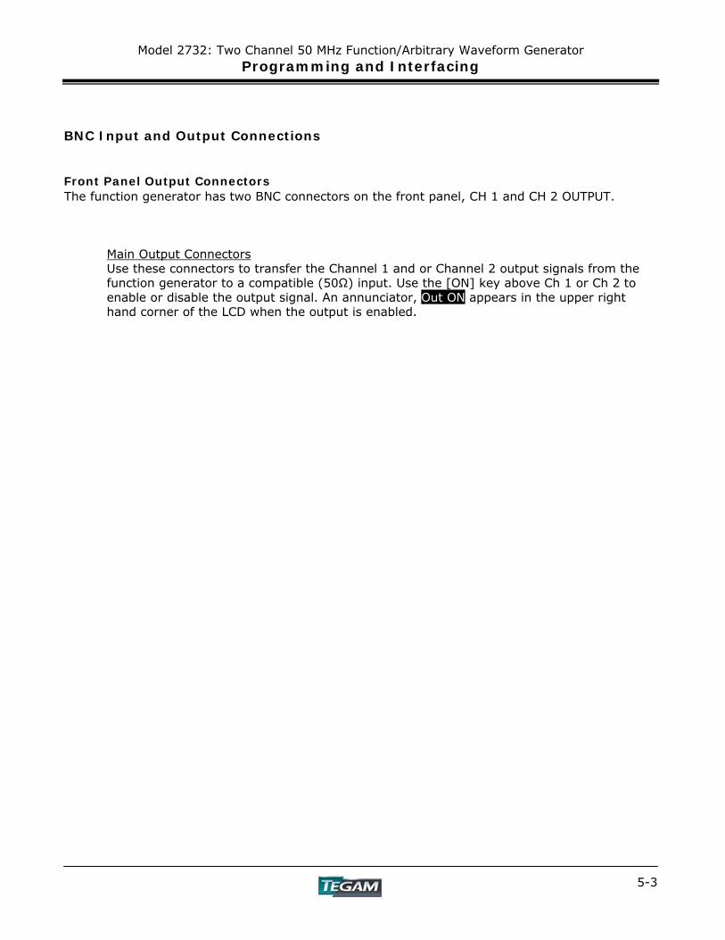
Model 2732: Two Channel 50 MHz Function/Arbitrary Waveform Generator Programming and Interfacing
5-3
BNC Input and Output Connections Front Panel Output Connectors The function generator has two BNC connectors on the front panel, CH 1 and CH 2 OUTPUT.
Main Output Connectors Use these connectors to transfer the Channel 1 and or Channel 2 output signals from the function generator to a compatible (50Ω) input. Use the [ON] key above Ch 1 or Ch 2 to enable or disable the output signal. An annunciator, Out ON appears in the upper right hand corner of the LCD when the output is enabled.
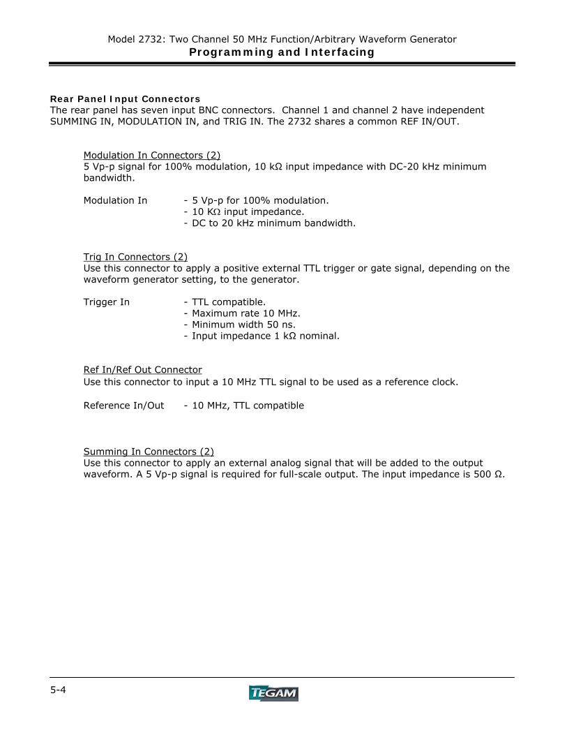
Model 2732: Two Channel 50 MHz Function/Arbitrary Waveform Generator Programming and Interfacing
5-4
Rear Panel Input Connectors The rear panel has seven input BNC connectors. Channel 1 and channel 2 have independent SUMMING IN, MODULATION IN, and TRIG IN. The 2732 shares a common REF IN/OUT.
Modulation In Connectors (2) 5 Vp-p signal for 100% modulation, 10 kΩ input impedance with DC-20 kHz minimum bandwidth.
Modulation In - 5 Vp-p for 100% modulation. - 10 KΩ input impedance.
- DC to 20 kHz minimum bandwidth. Trig In Connectors (2) Use this connector to apply a positive external TTL trigger or gate signal, depending on the waveform generator setting, to the generator.
Trigger In - TTL compatible. - Maximum rate 10 MHz. - Minimum width 50 ns.
- Input impedance 1 kΩ nominal. Ref In/Ref Out Connector Use this connector to input a 10 MHz TTL signal to be used as a reference clock. Reference In/Out - 10 MHz, TTL compatible
Summing In Connectors (2) Use this connector to apply an external analog signal that will be added to the output waveform. A 5 Vp-p signal is required for full-scale output. The input impedance is 500 Ω.
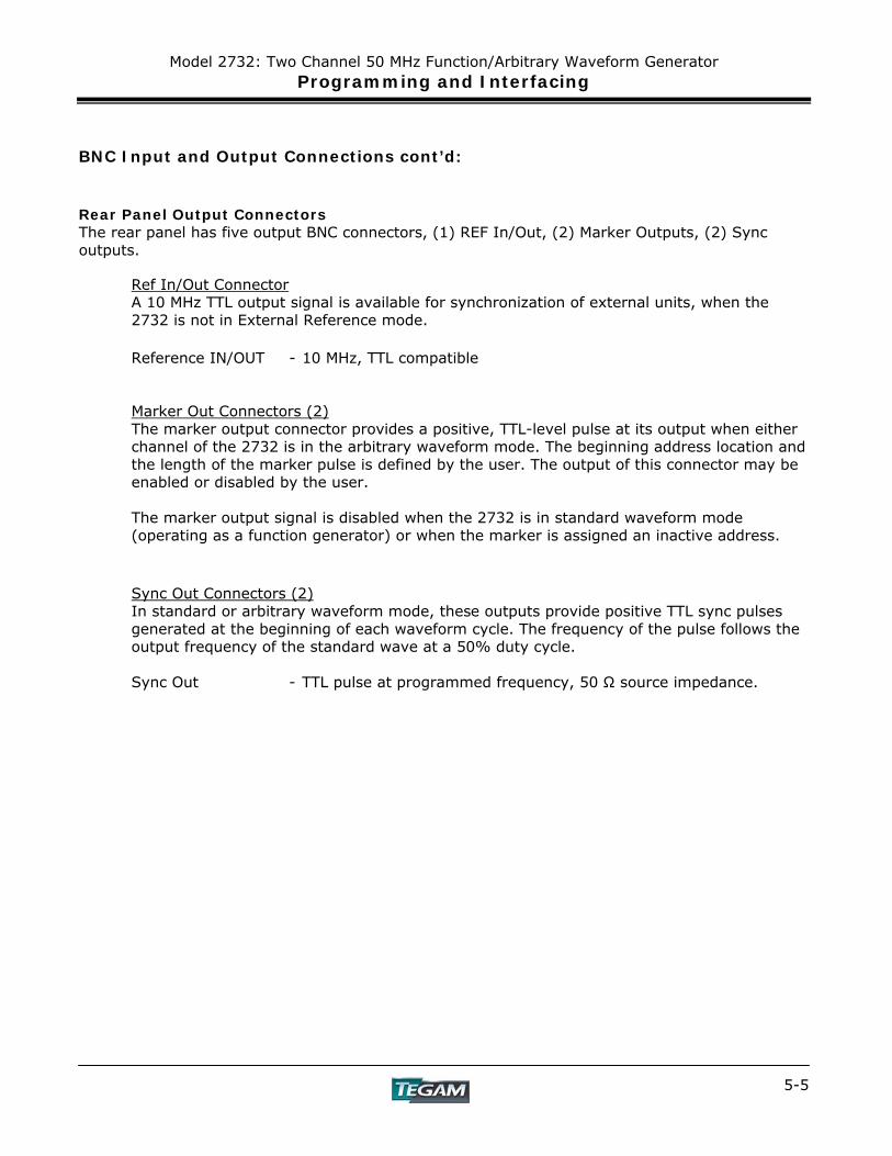
Model 2732: Two Channel 50 MHz Function/Arbitrary Waveform Generator Programming and Interfacing
5-5
BNC Input and Output Connections cont’d: Rear Panel Output Connectors The rear panel has five output BNC connectors, (1) REF In/Out, (2) Marker Outputs, (2) Sync outputs.
Ref In/Out Connector A 10 MHz TTL output signal is available for synchronization of external units, when the 2732 is not in External Reference mode.
Reference IN/OUT - 10 MHz, TTL compatible
Marker Out Connectors (2) The marker output connector provides a positive, TTL-level pulse at its output when either channel of the 2732 is in the arbitrary waveform mode. The beginning address location and the length of the marker pulse is defined by the user. The output of this connector may be enabled or disabled by the user. The marker output signal is disabled when the 2732 is in standard waveform mode (operating as a function generator) or when the marker is assigned an inactive address.
Sync Out Connectors (2) In standard or arbitrary waveform mode, these outputs provide positive TTL sync pulses generated at the beginning of each waveform cycle. The frequency of the pulse follows the output frequency of the standard wave at a 50% duty cycle.
Sync Out - TTL pulse at programmed frequency, 50 Ω source impedance.
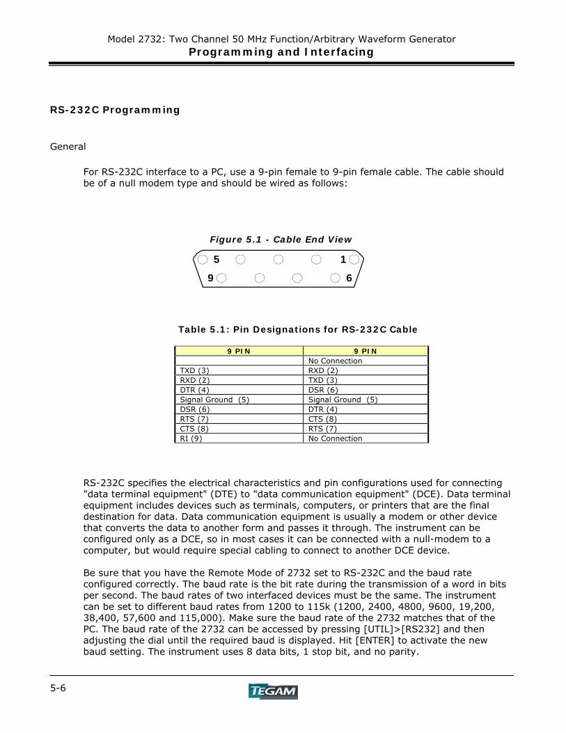
Model 2732: Two Channel 50 MHz Function/Arbitrary Waveform Generator Programming and Interfacing
5-6
RS-232C Programming
General
For RS-232C interface to a PC, use a 9-pin female to 9-pin female cable. The cable should be of a null modem type and should be wired as follows:
Figure 5.1 - Cable End View
Table 5.1: Pin Designations for RS-232C Cable
9 PIN 9 PIN No Connection
TXD (3) RXD (2) RXD (2) TXD (3) DTR (4) DSR (6) Signal Ground (5) Signal Ground (5) DSR (6) DTR (4) RTS (7) CTS (8) CTS (8) RTS (7) RI (9) No Connection
RS-232C specifies the electrical characteristics and pin configurations used for connecting "data terminal equipment" (DTE) to "data communication equipment" (DCE). Data terminal equipment includes devices such as terminals, computers, or printers that are the final destination for data. Data communication equipment is usually a modem or other device that converts the data to another form and passes it through. The instrument can be configured only as a DCE, so in most cases it can be connected with a null-modem to a computer, but would require special cabling to connect to another DCE device.
Be sure that you have the Remote Mode of 2732 set to RS-232C and the baud rate configured correctly. The baud rate is the bit rate during the transmission of a word in bits per second. The baud rates of two interfaced devices must be the same. The instrument can be set to different baud rates from 1200 to 115k (1200, 2400, 4800, 9600, 19,200, 38,400, 57,600 and 115,000). Make sure the baud rate of the 2732 matches that of the PC. The baud rate of the 2732 can be accessed by pressing [UTIL]>[RS232] and then adjusting the dial until the required baud is displayed. Hit [ENTER] to activate the new baud setting. The instrument uses 8 data bits, 1 stop bit, and no parity.
1
6
5
9
Model 2732: Two Channel 50 MHz Function/Arbitrary Waveform Generator Programming and Interfacing
5-7
RS-232C Programming
Data signals over the RS-232C use a voltage of +3 V to +25 V to represent a zero (called a space) and a voltage of -3V to -25V to represent a one (called a mark). Handshake and control lines use +3 V to +25 V to indicate a true condition and –3 V to –25 V to indicate a false condition. When no data is being transmitted, the idle state of the data lines will be the mark state. To transmit a byte, the transmitting device first sends a start bit to synchronize the receiver.
RS-232C Operation
The RS-232C standard is not very specific about many of the handshaking signals and it is therefore usually necessary to refer to the manuals for both of the devices being connected to determine the exact pin out, signal definition, and signal direction for the devices.
The serial interface implements the same SCPI command set as the GPIB interface. The instrument is programmed by sending ASCII coded characters to the instrument. When the instrument is in the remote mode, remote command input has priority over any front panel control. Therefore, as long as the serial interface is continuously supplied with data, the front panel keys will appear to be inoperative to the user.
The instrument accepts a carriage return (CR) as an end of string (EOS) terminator and sends both a CR and line feed (LF) as the EOS terminator.
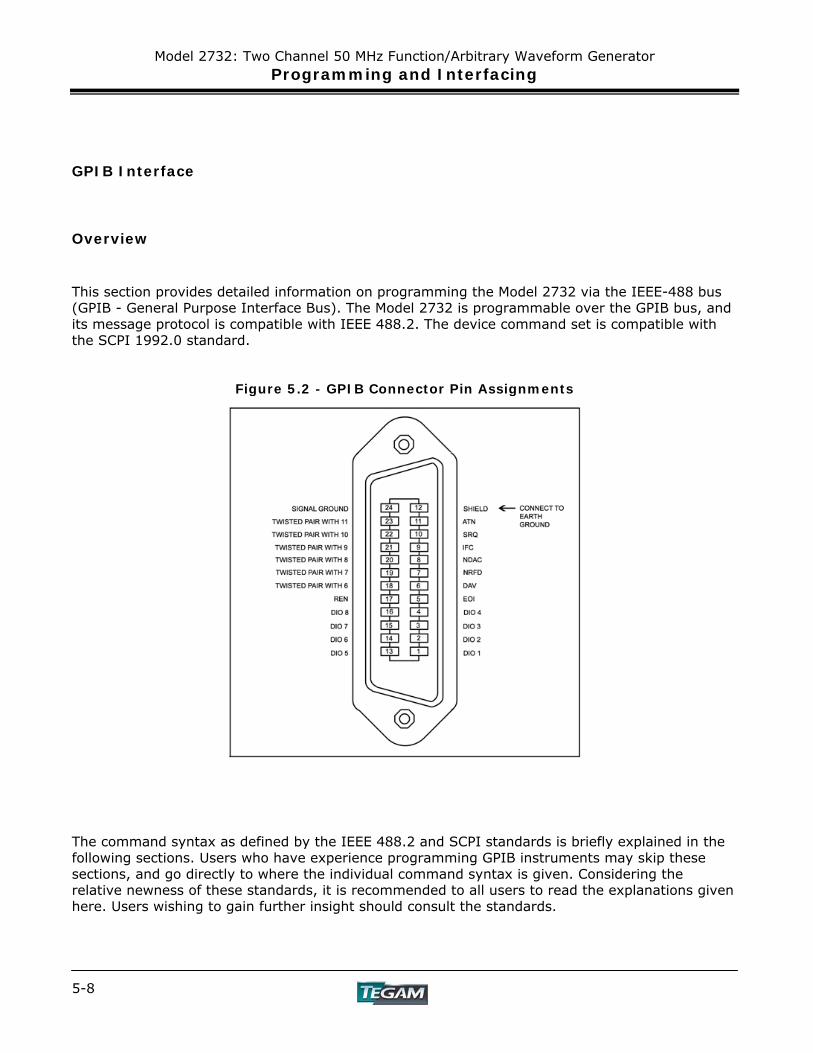
Model 2732: Two Channel 50 MHz Function/Arbitrary Waveform Generator Programming and Interfacing
5-8
GPIB Interface
Overview This section provides detailed information on programming the Model 2732 via the IEEE-488 bus (GPIB - General Purpose Interface Bus). The Model 2732 is programmable over the GPIB bus, and its message protocol is compatible with IEEE 488.2. The device command set is compatible with the SCPI 1992.0 standard.
Figure 5.2 - GPIB Connector Pin Assignments
The command syntax as defined by the IEEE 488.2 and SCPI standards is briefly explained in the following sections. Users who have experience programming GPIB instruments may skip these sections, and go directly to where the individual command syntax is given. Considering the relative newness of these standards, it is recommended to all users to read the explanations given here. Users wishing to gain further insight should consult the standards.

Model 2732: Two Channel 50 MHz Function/Arbitrary Waveform Generator Programming and Interfacing
5-9
Device State The 2732 may be in one of four possible states described below. The transition between states is defined by IEEE 488.1.
Local State (LOCS)
In the LOCS the device may be operated from the front panel only. Its settings may be queried over the GPIB, but not changed. Commands that do not affect the signal being output by the instrument are accepted.
Local With Lockout State (LWLS)
In the LWLS the device may be operated from the front panel only. Its settings may be queried over the GPIB, but not changed. Commands that do not affect the signal being output by the instrument are accepted. The difference between the LOCS and the LWLS is that the LWLS device may enter the Remote With Lockout State.
Remote State (REMS)
In the REMS the device may be operated from the GPIB. Actuating any front panel key will cause the device state to revert to the LOCS.
Remote With Lockout State (RWLS)
In the RWLS the device is operable only from the GPIB. Front panel operation may be returned by either sending an appropriate IEEE 488.2 command, or by cycling the device power.
Model 2732: Two Channel 50 MHz Function/Arbitrary Waveform Generator Programming and Interfacing
5-10
Interface Function Subsets The following interface function subsets are implemented in the Model 2732: SH1, AH1, T6, L4, SR1, RL1, PP0, DC1, DT1, E2, C0 Device Address The GPIB address of the 2732 may be set to any value from 0 to 31. The address may be changed from the front panel, using the numeric keypad or the rotary encoder, or via the GPIB itself using the command: :SYSTem:COMMunicate:GPIB:ADDRess Setting the device to address 31 puts it in the 'off-bus' state. In this state it will not respond to messages on the GPIB. If the device is in the REMS when set to address 31, an internal 'return-to-local' command will be given, setting the device to the LOCS. If the device is in the RWLS, the 'return-to-local' command is ignored, and the device remains in the RWLS. The only way to then re-establish communication with the device over the GPIB is to cycle the power, and to then change the address to that required from the front panel. Message Exchange Protocol (MEP) The 2732 decodes messages using the Message Exchange Protocol defined in IEEE 488.2. The following functions implemented in the MEP must be considered:
The Input Buffer
The device has a 256-byte long cyclic input buffer. Decoding of remote messages is begun as soon as the input buffer is not empty, that is, as soon as the controller has sent at least one byte to the device. Should the input buffer be filled up by the controller faster than the device can remove the bytes and decode them, the bus handshake is not completed until room has been made for more bytes in the buffer. This prevents a fast controller from overrunning the device with data. If the user has sent part of a Program Message, but not the Program Message Terminator, and he wishes to abort the message decoding and execution, the Device Clear command may be sent, or front panel operation resumed (in REMS only).
The Output Queue
The device has a 100-byte long output queue in which it stores response messages for the controller to read. If at the time a response message is formatted the queue contains previously formatted response messages, such that there is not enough place in the queue for the new message, the device will put off putting the message in the queue until there is room for it.
When the Status Byte MAV bit is set, it indicates that all or part of a response message is ready to be read.
Model 2732: Two Channel 50 MHz Function/Arbitrary Waveform Generator Programming and Interfacing
5-11
Response Messages
The device sends a Response Message in response to a valid query. All queries return a single Response Message Unit. In only one case is the Response Message generated when the response is read (as opposed to when the response is parsed), and this is when querying Arbitrary Waveform data. All other queries generate the Response Message when they are parsed.
Coupled Commands
Coupled Commands are either commands whose execution validity depends on the value of other parameters, or commands whose execution changes the value of another parameter. The execution of commands designated as being coupled is deferred until all other commands in the same Program Message have been executed. The coupled commands are then grouped together according to their functionality, and executed as a group. These groups of coupled commands are defined in the Model 2732:
a) Commands to set the amplitude, the offset, and to switch the output on. The output
being switched on is included here in order to prevent possible damage to the equipment being driven as a result of the amplitude and offset not being executed as intended by the user, due to an execution error.
b) Commands to set the function, frequency, the point rate, the wavelength, and the
waveform start address. In ARB mode, the frequency and the point execution rate are dependent upon each other keeping the wavelength constant (unless it is specified in the same program message). If the wavelength is specified as well, the frequency or point rate must change in accordance with the new value. The validity of the start address is a function of the wavelength. Please refer to the individual commands for more detail. The maximum frequency is also dependant upon the waveform, so that changing the waveform may render the current frequency out of range.
c) Commands to set modulation, modulation source and the function are inter-related. FM
and FSK are not available for ARB function. External source of modulation can be active for either FM or AM but not both. FSK and FM cannot be active at the same time.
d) Sweep start and sweep stop frequencies must be distanced more than the minimum
allowed for sweep to function correctly.
Model 2732: Two Channel 50 MHz Function/Arbitrary Waveform Generator Programming and Interfacing
5-12
Block Data Arbitrary waveform values may be sent to the device in one of three formats: a) ASCII values, b) Definite form arbitrary data, and c) Indefinite form arbitrary data. Essentially we would like to check the execution validity of all the data of a command before execution. When downloading a long arbitrary waveform, however, it is not possible to check all the data sent before execution, since this would require excessive amounts of memory. The following compromise has therefore been reached: An arbitrary waveform is limited in length only by the amount of waveform memory. Each point is checked and then written to memory. If an invalid value is detected all subsequent values are discarded, and an execution error is flagged. Querying arbitrary waveform data will result in a Response Message containing only as many points as the user requested. Instrument Identification The *IDN? common query is used to read the instrument's identification string. As of September 2006, the string returned is as follows: Tegam, 2732,0,V1.XX Instrument Reset The *RST common command restores an instrument to its factory default settings. Self Test The *TST common query causes the device to perform a self-test. This self-test consists of checking the functionality of the arbitrary waveform memory.
Model 2732: Two Channel 50 MHz Function/Arbitrary Waveform Generator Programming and Interfacing
5-13
Command Syntax
General Command Structure
The device commands are generally defined by the SCPI standard, with the exception of those instrument functions for which SCPI commands do not as yet exist. The Common Commands and Queries are defined by IEEE 488.2. The command syntax, i.e., how a command is structured, is defined by IEEE 488.2.
A Program Message is defined as a string containing one or more Program Message Units, each of which is an instrument command or query. Program Message Units are separated from each other by the Program Message Unit Separator. The Program Message is terminated by the Program Message Terminator.
The Program Message Unit Separator consists of a semicolon (';'), optionally preceded and/or followed by white space characters. A white space character is defined as the ASCII characters in the ranges 00H-09H, and 0BH-20H. This range includes the ASCII control characters and the space, but excludes the Linefeed character.
The Program Message Terminator consists of optional white space characters, followed by one of three options:
a) The Linefeed (LF) character (ASCII 0A); b) The GPIB EOI bus line being set true on the last byte of the message; c) LF being sent with EOI true. The Program Message Unit can be divided into three sections as follows: a) Program Header
The Program Header represents the operation to be performed, and consists of ASCII character mnemonics. Two types of Program Headers are used in the 2732: Instrument-control headers and Common Command and Query headers. A Program Header may consist of more than one mnemonic, in which case the mnemonics are separated from each other by the colon (':'). For instrument control commands, the mnemonics are specified by the SCPI standard, and indicate the tree structure of the command set. The first mnemonic indicates the subsystem being controlled. Common Command and Query Program Headers consist of a single mnemonic prefixed by an asterisk ('*').

Model 2732: Two Channel 50 MHz Function/Arbitrary Waveform Generator Programming and Interfacing
5-14
The mnemonics consist of upper - or lower-case alpha characters. Mnemonics may be written in either the long form, in which the entire mnemonic is written out, or the short form, in which only a specified portion of the mnemonic is written out. Some mnemonics have only one form due to their short length. Where a command is described, the portion appearing in upper case is the short form. Only the short form or the long form may be used.
Example: The command to set the frequency to 1KHZ may be written in the following ways:
SOURCE:FREQUENCY 1KHZ SOUR:FREQ 1KHZ SOURCE:FREQ 1KHZ
*Note: To use channel 2, replace “SOURCE” with “SOURCE2” or “SOUR” with, “SOUR2”. Some mnemonics in a specified Program Header may be optional. This is indicated in the command description by the mnemonic being enclosed in square brackets ([...]). This means it is not necessary to write the mnemonic when addressing Channel 1: it is a default condition. The 'SOURCE' mnemonic, for example, is optional. Not specifying it will cause the device to search for the mnemonics in the Program Header under the Source Subsystem. For example, the frequency may be set by the commands since the 'CW' mnemonic is also optional.
FREQ:CW 1KHz FREQ 1KHz
*Note: To access Channel 2, you must specify the second channel subset of commands. In the example above you would still need to include SOURCE2: “SOUR2:FREQ 1KHz”
b) Program Header Separator
The Program Header Separator is used to separate the program header from the program data. It consists of one or more white space characters, denoted as <ws>. Typically, it is a space.
c) Program Data
The Program Data represent the values of the parameters being set, for example, the '1KHZ' in the above examples. Different forms of program data are accepted, depending on the command. The Program Data types used in the instrument are:
i) Character Program Data
This form of data is comprised of a mnemonic made up of lower - or upper-case alpha characters. As with Program Header mnemonics, some Character Data mnemonics have short and long forms. Only the short or the long form may be used.
Model 2732: Two Channel 50 MHz Function/Arbitrary Waveform Generator Programming and Interfacing
5-15
ii) Boolean data Boolean data indicate that the parameter can take one of two states, ON or OFF. The parameter may be character type or numeric.
ON or OFF
A numeric value is rounded to an integer. A non-zero result is interpreted as 1 (ON), and a zero result as 0 (OFF).
Queries return the values 0 or 1.
iii) NRf This is a decimal numeric data type, where (f=1, 2, or 3) NR1 indicates an integer number, NR2 indicates a fixed point real number, and NR3 indicates a floating-point real number. iv) Expression Data
An expression is contained in parentheses (...). This data type is used only with the STATus:QUEue:ENABle command.
v) Numeric Value Program Data
This data type defines numeric values, as well as special cases of Character Data. Numeric values may be specified in any of Integer, Fixed Point or Floating Point format. All parameters, which have associated units accept a suffix, which may be specified using upper or lower-case characters. When the suffix is not specified, the numeric value is accepted in the default units, which are Hertz for frequency, Seconds for time, and Volts for voltage. To set the frequency on Channel 1 to 1KHz we can send one of the following commands:
FREQ 1000 FREQ 1E3 The special forms of character data accepted as numbers are MAXimum: sets the parameter to its maximum value. MINimum: sets the parameter to its minimum value. For example, to set the frequency to it's maximum value we can send the command FREQ MAX To set the maximum frequency on Channel 2 we can send the command SOURCE2:FREQ MAX
Model 2732: Two Channel 50 MHz Function/Arbitrary Waveform Generator Programming and Interfacing
5-16
vi) Arbitrary Block Data
The Arbitrary block data type is used to send arbitrary waveform data to the instrument. In this data type, the waveform points are specified in binary format, and each point consists of two bytes. Two types of arbitrary block data are defined (by IEEE 488.2):
Definite Form: The Definite Form has the structure
-#-Byte Count Length - Byte Count - 8-bit byte
The Byte Count Length consists of a single ASCII digit from 1 to 9. It tells the parser how many digits are in the Byte Count.
The Byte Count is a decimal integer made up of the number of digits specified in the Byte Count Length. It tells the parser how many 8-bit bytes are being sent.
Indefinite Form: The Indefinite Form has the structure
- # - 0 – 8-bit byte – LF^EOI
Some Program Message Units either require, or can accept, more than one data element. Program data elements are separated from each other by the Program Data Separator. It is defined as optional white space characters followed by a comma (','), which in turn is followed by optional white space characters.
There are two types of Program Message Units: Command Message Units and Query Message Units. A Query differs from a Command in that the Program Header is terminated with a question mark ('?'). For example, the frequency might be queried with the following query:
FREQ?
Some Query Message Units accept data, giving the device more specific information about what is being queried. In many cases the Query Message Unit may optionally be supplied with the MIN or MAX mnemonics as data. This tells the device to return the minimum or maximum value to which the parameter may currently be set. For example,
FREQ? MAX will return the maximum value to which the frequency may currently be set.
Model 2732: Two Channel 50 MHz Function/Arbitrary Waveform Generator Programming and Interfacing
5-17
Not all Program Message units have query forms (for example, STATUS: PRESET), and some Program Message Units might have only the query form (for example SYSTEM: VERSION?).
The instrument puts the response to the query into the output queue, from where it may be read by the controller. The Status Byte MAV bit is set to indicate to the controller that a response is ready to be read.
SCPI Command Structure
SCPI commands are based on a hierarchical structure. This allows the same instrument-control header to be used several times for different purposes, providing that the mnemonic occurs in a unique position in the hierarchy. Each level in the hierarchy is defined as a node. Mnemonics in the different levels are separated from each other by a colon (':'). The first Program Message Unit, or command, in a Program Message is always referenced to the root node. Subsequent commands are referenced to the same level as the previous command. A Program Message Unit having a colon as its first character causes the reference to return to the root. This process is defined by IEEE 488.2, section A.1.1. Consider the following examples:
a) The following command may be used to set the amplitude and the offset of the signal.
SOURCE:VOLTAGE:AMPLITUDE 5V;OFFSET 2V
Note that the offset command is referenced to the command preceding it: the OFFSET mnemonic resides at the same node as the AMPLITUDE command.
b) This command set the frequency and the amplitude for Channel 2. SOURCE2:FREQUENCY 2KHZ;VOLTAGE:AMPLITUDE 4V The FREQUENCY and VOLTAGE mnemonics are at the same level.
c) When Program Message Units describe different subsystems, a colon prefix must be used to reset the command reference to the root. Here the frequency and the output state are set.
SOURCE:FREQUENCY 3KHZ;:OUTPUT:STATE ON
Common Commands may be inserted in the Program Message without affecting the instrument-control command reference. For example,
SOURCE:VOLTAGE:AMPLITUDE 4V;*ESE 255;OFFSET 2V

Model 2732: Two Channel 50 MHz Function/Arbitrary Waveform Generator Programming and Interfacing
5-18
Status Reporting
The instrument is capable of reporting status events and errors to the controller, using the IEEE 488.2 Service Request function and the IEEE 488.2 Status Reporting structure.
The Status Byte
Status summary information is communicated from the device to the controller using the Status Byte (STB). The STB is composed of single-bit summary-messages, each summary message summarizing an overlying Status Data Structure. By examining the content of the STB, the controller gains some information concerning the instrument's status.
The STB bits are defined as follows: Bit 0: Unused Bit 1: Unused
Bit 2: Error/event queue summary message (EVQ). This bit is set if the queue is not empty.
Bit 3: Questionable Status summary message. Bit 4: Message Available (MAV) summary message. This bit is set whenever all or part of a
message is available for the controller to read. The controller may be ready to read the response message before it is available, in which case it can either wait until this bit is set, or it can start to read. In the second case, the controller timeout must be set so that the read action will not be aborted before the message has been read.
Bit 5: Event Status Bit (ESB) summary message. This bit is set to indicate that one or more of the enabled standard events have occurred.
Bit 6: Request Service (RQS). This bit is set when the device is actively requesting service. Bit 7: Operation Status summary message. No Operation Status events are defined in the
instrument, and so this bit is never set.
The STB is read by the controller during a serial poll. If the RQS bit was set, it is then cleared. The STB may also be read by the *STB? common query.
Service Request Enabling
Service request enabling allows the user to select which Status Byte summary messages may cause the device to actively request service. This is achieved using the Service Request Enable Register, which is an 8-bit register whose bits correspond to those of the STB. The RQS bit in the STB is set when a bit in the STB is set, and its corresponding bit in the service request enable register is set.
The service request enable register is set using the *SRE common command, and read using the *SRE? common query.
Model 2732: Two Channel 50 MHz Function/Arbitrary Waveform Generator Programming and Interfacing
5-19
Standard Event Status Register
The Standard Event Status Register (SESR) is defined by IEEE 488.2. It is implemented in the instrument as a byte, whose bits have the following definitions:
Bit 0: Operation Complete (OPC). This bit is set in response to the *OPC common
command being executed.
Bit 1: Request Control (RQC). Not implemented.
Bit 2: Query Error (QYE). This bit is set when either the controller is attempting to read data from the device when none is available, or when data prepared for the controller to read has been lost.
Bit 3: Device-Specific Error (DDE). This bit is set to indicate that a device operation did not
execute due to some device condition. For example, trying to recall an uninitialized device stored setting.
Bit 4: Execution Error (EXE). This bit is set when the device could not execute a command,
due to the command being outside of it's capabilities. For example, an out of range parameter.
Bit 5: Command Error (CME). This bit is set to indicate an error in the command syntax. Bit 6: User Request (URQ). This bit is not used. Bit 7: Power On (PON). This bit is set when the device is powered on. The SESR is queried using the *ESR? common query.
The SESR is paired with an enable register, the Standard Event Status Enable Register (SESER). This register enables one or more events in the SESR to be reflected in the Status Byte ESB summary message bit. The bits of the SESER correspond to those of the SESR. Setting a bit in the SESER enables the corresponding event to set the ESB bit when it occurs. The SESER is set with the *ESE common command and queried with the *ESE? command query.
The Error Queue
The error queue is used to store codes of errors detected in the device. It is implemented as a cyclic buffer of length 10. When the error queue is not empty, bit EVQ in the Status Byte is set. The error queue is read with either one of the following two queries:
:SYSTEM:ERROR? :STATUS:QUEUE:NEXT? The first error in the queue is returned, and the queue is advanced.
Model 2732: Two Channel 50 MHz Function/Arbitrary Waveform Generator Programming and Interfacing
5-20
Error Codes The negative error codes are defined by SCPI. Positive codes are specific to the instrument. The error message is returned in the form <error number>,"<error description>" A table of error numbers and their descriptions is presented here. No error reported 0 No error Command Errors
A command error is in the range -199 to -100, and indicates that a syntax error was detected. This includes the case of an unrecognized header. The occurrence of a command error causes the CME bit (bit 5) of the Standard Event Status Register to be set.
Table 5.2: Summary of Command Errors
ERROR CODE
DESCRIPTION ERROR CODE
DESCRIPTION
100 Command Error 124
Too many digits. Maximum of 255 digits in mantissa.
101 Invalid character 128
Numeric data not allowed. A different data type was expected
102 Syntax error 131 Invalid suffix 103
Invalid separator 134
Suffix too long. A maximum of 12 characters are allowed.
104 Data type error 138 Suffix not allowed 105 GET not allowed 140 Character data error. 108 Parameter not allowed.
More parameters than allowed were received.
141 Invalid character data. Incorrect character data was received.
109 Missing parameter. Fewer parameters than necessary were received
144
Character data too long. Character data may contain no more than 12 characters.
110 Command header error 148 Character data not allowed 111 Header separator error 158 String data not allowed 112 Program mnemonic too long.
No more than 12 characters allowed. 161 Invalid block data.
An error was found in the block data 113 Undefined header 168 Block data not allowed 120 Numeric data error 170
Expression error. Only 6 error ranges may be specified.
121 Invalid character in number 171 Invalid expression. An error was found in the expression.
123 Exponent too large. IEEE 488.2 specifies maximum of 32000
178
Expression data not allowed
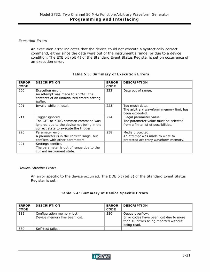
Model 2732: Two Channel 50 MHz Function/Arbitrary Waveform Generator Programming and Interfacing
5-21
Execution Errors
An execution error indicates that the device could not execute a syntactically correct command, either since the data were out of the instrument's range, or due to a device condition. The EXE bit (bit 4) of the Standard Event Status Register is set on occurrence of an execution error.
Table 5.3: Summary of Execution Errors ERROR CODE
DESCRIPTION ERROR CODE
DESCRIPTION
200 Execution error. An attempt was made to RECALL the contents of an uninitialized stored setting buffer.
222 Data out of range.
201 Invalid while in local. 223 Too much data. The arbitrary waveform memory limit has been exceeded.
211 Trigger ignored. The GET or *TRG common command was ignored due to the device not being in the correct state to execute the trigger.
224 Illegal parameter value. The parameter value must be selected from a finite list of possibilities.
220 Parameter error. A parameter is in the correct range, but conflicts with other parameters.
258 Media protected. An attempt was made to write to protected arbitrary waveform memory.
221 Settings conflict. The parameter is out of range due to the current instrument state.
Device-Specific Errors
An error specific to the device occurred. The DDE bit (bit 3) of the Standard Event Status Register is set.
Table 5.4: Summary of Device Specific Errors
ERROR CODE
DESCRIPTION ERROR CODE
DESCRIPTION
315 Configuration memory lost. Device memory has been lost.
350 Queue overflow. Error codes have been lost due to more than 10 errors being reported without being read.
330 Self-test failed.
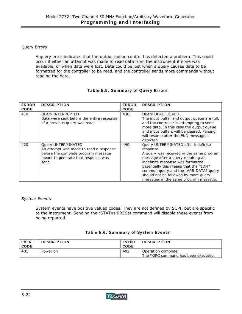
Model 2732: Two Channel 50 MHz Function/Arbitrary Waveform Generator Programming and Interfacing
5-22
Query Errors
A query error indicates that the output queue control has detected a problem. This could occur if either an attempt was made to read data from the instrument if none was available, or when data were lost. Data could be lost when a query causes data to be formatted for the controller to be read, and the controller sends more commands without reading the data.
Table 5.5: Summary of Query Errors
ERROR CODE
DESCRIPTION ERROR CODE
DESCRIPTION
410 Query INTERRUPTED. Data were sent before the entire response of a previous query was read.
430 Query DEADLOCKED. The input buffer and output queue are full, and the controller is attempting to send more data. In this case the output queue and input buffers will be cleared. Parsing will resume after the END message is detected.
420 Query UNTERMINATED. An attempt was made to read a response before the complete program message meant to generate that response was sent.
440 Query UNTERMINATED after indefinite response. A query was received in the same program message after a query requiring an indefinite response was formatted. Essentially this means that the *IDN? common query and the :ARB:DATA? query should not be followed by more query messages in the same program message.
System Events
System events have positive valued codes. They are not defined by SCPI, but are specific to the instrument. Sending the :STATus:PRESet command will disable these events from being reported.
Table 5.6: Summary of System Events
EVENT CODE
DESCRIPTION EVENT CODE
DESCRIPTION
401 Power on 402 Operation complete The *OPC command has been executed.
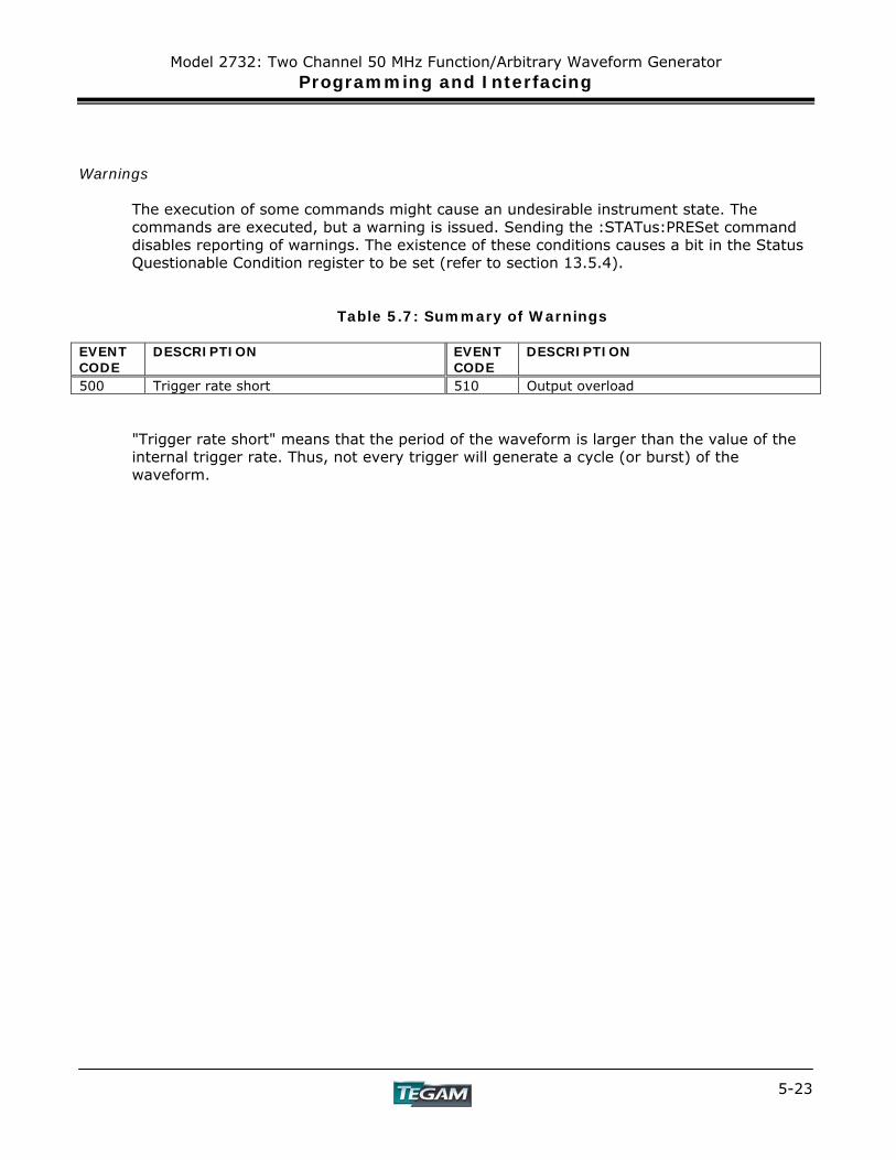
Model 2732: Two Channel 50 MHz Function/Arbitrary Waveform Generator Programming and Interfacing
5-23
Warnings
The execution of some commands might cause an undesirable instrument state. The commands are executed, but a warning is issued. Sending the :STATus:PRESet command disables reporting of warnings. The existence of these conditions causes a bit in the Status Questionable Condition register to be set (refer to section 13.5.4).
Table 5.7: Summary of Warnings
EVENT CODE
DESCRIPTION EVENT CODE
DESCRIPTION
500 Trigger rate short 510 Output overload
"Trigger rate short" means that the period of the waveform is larger than the value of the internal trigger rate. Thus, not every trigger will generate a cycle (or burst) of the waveform.
Model 2732: Two Channel 50 MHz Function/Arbitrary Waveform Generator Programming and Interfacing
5-24
IEEE 488.2 Common Commands
System Data Commands
a) *IDN? - Identification query
The identification query enables unique identification of the device over the GPIB. This query should always be the last in a program message. It returns a string with four fields:
Manufacturer name Model name Serial number (0 if not relevant) Version number
Command Type: Common Query Syntax: *IDN? Response: TEGAM, 2732,0,V1.XX
b) *OPT? - Option identification query
The Option Identification Query is used to identify device options over the system interface. This query should always be the last in a program message.
Command Type: Common Query Syntax: *OPT? Response: No option available.
Internal Operation Commands
a) *RST - Reset command
The Reset command performs a device reset. It causes the device to return to the factory default power up state.
Type: Common Command Syntax: *RST
b)*TST? - Self-test query
The self-test query causes an internal self-test to be performed. This test consists of checking the integrity of the arbitrary waveform memory.
Type: Common Query Syntax: *TST? Response: ASCII 0 if test passes
ASCII 1 if test fails
Model 2732: Two Channel 50 MHz Function/Arbitrary Waveform Generator Programming and Interfacing
5-25
Synchronization Commands
a) *OPC - Operation complete command
The operation complete command causes the device to generate the operation complete message in the Standard Event Status Register, on completion of the selected device operation.
Type: Common Command
Syntax: *OPC Examples: FREQ 5KHZ;*OPC
The *OPC command (and the *OPC? query described below) find use mainly when commands having relatively long execution times are executed, for example the programming of long predefined waveforms.
b) *OPC? - Operation complete query
The operation complete query places an ASCII character 1 in the output queue on completion of the selected device operation.
Type: Common Query Syntax: *OPC? Response: ASCII character 1 Example FREQ 1KHz;*OPC?
c) *WAI - Wait-to-continue command
This command is intended for use with overlapped commands. No commands in the instrument are overlapped, and so this command has no effect.
Type: Common Command Syntax: *WAI
Model 2732: Two Channel 50 MHz Function/Arbitrary Waveform Generator Programming and Interfacing
5-26
Status and Event Commands
a) *CLS - Clear status The clear status command clears the SESR and Error Queue status data structures.
Type: Common Command Syntax: *CLS
b) *ESE - Standard event status enable
This command is used to set the value of the Standard Event Status Enable Register.
Arguments Type: NRf Range: 0 to 255. Non-integer arguments are rounded before execution. Type: Common Command or Query Syntax: *ESE<ws><NRf> Examples: *ESE 48 (Enables the CME and EXE bits)
*ESE 255 (Enables all standard events) Query Syntax: *ESE? Response: <NR1>
c) *ESR? - Standard event status register query
This query is used to read the value of the Standard Event Status Register. Reading the register clears it.
Type: Common Query Syntax: *ESR? Response: <NR1>
Model 2732: Two Channel 50 MHz Function/Arbitrary Waveform Generator Programming and Interfacing
5-27
d) *PSC - Power on status clear command
This command is used to control the automatic power-on clearing of certain status functions.
Arguments Type: Boolean Type: Common Command or Query Command Syntax: *PSC<ws><Boolean> Examples: *PSC ON or *PSC 1
*PSC OFF or *PSC 0 Query Syntax: *PSC? Response: ASCII 0 for OFF
ASCII 1 for ON
When set to ON (1), the Service Request Enable Register and the Standard Event Status Enable Register are cleared on power-on.
e) *SRE - Service request enable command This command sets the Service Request Enable Register bits.
Arguments Type: NRf Range: 0 to 255. Non integer arguments are rounded before execution.
The value of bit 6 is ignored, and is set always to zero. Type: Common Command or Query Command Syntax: *SRE<ws><NRf> Examples: *SRE 48 (Enables reporting of ESB and MAV events) Query Syntax: *SRE? Response: <NR1>
Model 2732: Two Channel 50 MHz Function/Arbitrary Waveform Generator Programming and Interfacing
5-28
f) *STB? - Status byte query
This query is used to read the value of the Status Byte.
Type: Common Query Syntax: *STB? Response: <NR1>
The value of the Status Byte read with the *STB? query may differ from that read with the Serial Poll. Bit 6 of the STB will be set as long as a reason for requesting service exists, while bit 6 of the STB as read by the Serial Poll is cleared by the Serial Poll.
Device Trigger Commands
a) *TRG - Trigger command
This command is analogous to the IEEE 488.1 Group Execute Trigger interface message, and has the same effect. It is used to trigger the device to output a wave, and is accepted only when the trigger mode is set to Trigger, Gate or Burst, and the trigger source is set to BUS.
Type: Common Command Syntax: *TRG
Stored Settings Commands
a) *RCL - Recall instrument state
This command is used to restore the state of the device to that stored in the specified memory location.
Arguments Type <NRf> Range 0 to 49. Non integer values are rounded before execution
Type: Common Command Syntax: *RCL<ws><NRf> Example: *RCL 0 (Recall default state)
*RCL 49 Stored setting location 49 stores the last instrument setting before power down.
Model 2732: Two Channel 50 MHz Function/Arbitrary Waveform Generator Programming and Interfacing
5-29
b) *SAV - Save instrument state
This command is used to store the current instrument state in the specified memory location.
Arguments Type: <NRf> Range: 1 to 49. Non-integer values are rounded before execution Type: Common Command Syntax: *SAV<ws><NRf> Example: *SAV 25
Stored setting location 0 stores the factory defaults, and is a read-only location. Location 50 stores a copy of the current instrument setting, and it, too, is read-only.
Instrument Control Commands Instrument control commands are grouped into logical subsystems according to the SCPI instrument model. The commands are comprised of mnemonics indicating the subsystem to which the command belongs, and the hierarchy within that subsystem. When the command is to be referred to the Root node, it should be prefixed with a colon (:). Mnemonics appearing in square brackets [...] are optional. The '|' character is used to denote a choice of specifications. The '<ws>' is used to denote a white space character.
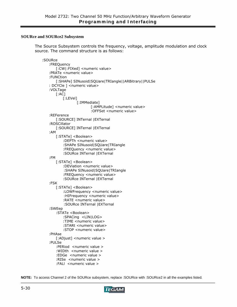
Model 2732: Two Channel 50 MHz Function/Arbitrary Waveform Generator Programming and Interfacing
5-30
SOURce and SOURce2 Subsystem
The Source Subsystem controls the frequency, voltage, amplitude modulation and clock source. The command structure is as follows:
:SOURce :FREQuency [:CW|:FIXed] <numeric value> :PRATe <numeric value> :FUNCtion [:SHAPe] SINusoid|SQUare|TRIangle||ARBitrary||PULSe : DCYCle ] <numeric value> :VOLTage [:AC] [:LEVel] [:IMMediate] [:AMPLitude] <numeric value> :OFFSet <numeric value> :REFerence [:SOURCE] INTernal |EXTernal :ROSCillator [:SOURCE] INTernal |EXTernal :AM [:STATe] <Boolean>
:DEPTh <numeric value> :SHAPe SINusoid|SQUare|TRIangle :FREQuency <numeric value> :SOURce INTernal |EXTernal :FM
[:STATe] <Boolean> :DEViation <numeric value> :SHAPe SINusoid|SQUare|TRIangle :FREQuency <numeric value> :SOURce INTernal |EXTernal
:FSK [:STATe] <Boolean>
:LOWFrequency <numeric value> :HIFrequency <numeric value> :RATE <numeric value> :SOURce INTernal |EXTernal
:SWEep :STATe <Boolean> :SPACing <LIN|LOG> :TIME <numeric value> :STARt <numeric value> :STOP <numeric value> :PHAse [:ADjust] <numeric value > :PULSe :PERiod <numeric value > :WIDth <numeric value > :EDGe <numeric value > :RISe <numeric value > :FALl <numeric value > NOTE: To access Channel 2 of the SOURce subsystem, replace :SOURce with :SOURce2 in all the examples listed.
Model 2732: Two Channel 50 MHz Function/Arbitrary Waveform Generator Programming and Interfacing
5-31
Frequency
:SOURce:FREQuency <frequency> The frequency command controls the frequency of the output waveform. Arguments Type: Numeric. Units: MHz, KHz, Hz (default) Range: Dependent on the Point Rate and Wavelength. Fmax = 1/(12.5 nS * Wavelength) Fmin = 1/(100S * Wavelength) Rounding: The value is rounded to 4 digits. Command Types: Setting or Query Setting Syntax: [:SOURce]:FREQuency[:CW]<ws><frequency>[units] [:SOURce]:FREQuency<ws>MINimum|MAXimum Examples: :FREQ 5KHZ :FREQ 5E3 :FREQ MAXIMUM :FREQ MIN Query Syntax: [:SOURce]:FREQuency[:CW]?[<ws>MAXimum|MINimum] Examples: :FREQ? :FREQ? MAX Response: NR3
Considerations:
1) The MIN | MAX arguments should be used only in a Program Message that does NOT contain Program Message Units specifying Arbitrary Point Rate or Wavelength, since the MAXimum or MINimum value is calculated at the time the command is parsed.
2) The MIN and MAX arguments refer to currently settable minimum or
maximum.
3) FIXed is alias for CW. NOTE: To access Channel 2 of the SOURce subsystem, replace :SOURce with :SOURce2 in all the examples listed.
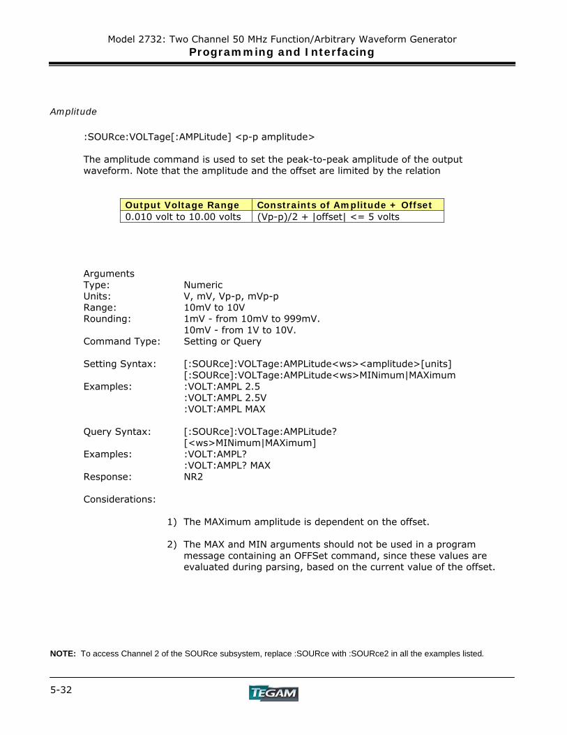
Model 2732: Two Channel 50 MHz Function/Arbitrary Waveform Generator Programming and Interfacing
5-32
Amplitude
:SOURce:VOLTage[:AMPLitude] <p-p amplitude>
The amplitude command is used to set the peak-to-peak amplitude of the output waveform. Note that the amplitude and the offset are limited by the relation
Output Voltage Range Constraints of Amplitude + Offset 0.010 volt to 10.00 volts (Vp-p)/2 + |offset| <= 5 volts
Arguments Type: Numeric Units: V, mV, Vp-p, mVp-p Range: 10mV to 10V Rounding: 1mV - from 10mV to 999mV.
10mV - from 1V to 10V. Command Type: Setting or Query Setting Syntax: [:SOURce]:VOLTage:AMPLitude<ws><amplitude>[units]
[:SOURce]:VOLTage:AMPLitude<ws>MINimum|MAXimum Examples: :VOLT:AMPL 2.5
:VOLT:AMPL 2.5V :VOLT:AMPL MAX
Query Syntax: [:SOURce]:VOLTage:AMPLitude?
[<ws>MINimum|MAXimum] Examples: :VOLT:AMPL?
:VOLT:AMPL? MAX Response: NR2
Considerations:
1) The MAXimum amplitude is dependent on the offset. 2) The MAX and MIN arguments should not be used in a program
message containing an OFFSet command, since these values are evaluated during parsing, based on the current value of the offset.
NOTE: To access Channel 2 of the SOURce subsystem, replace :SOURce with :SOURce2 in all the examples listed.
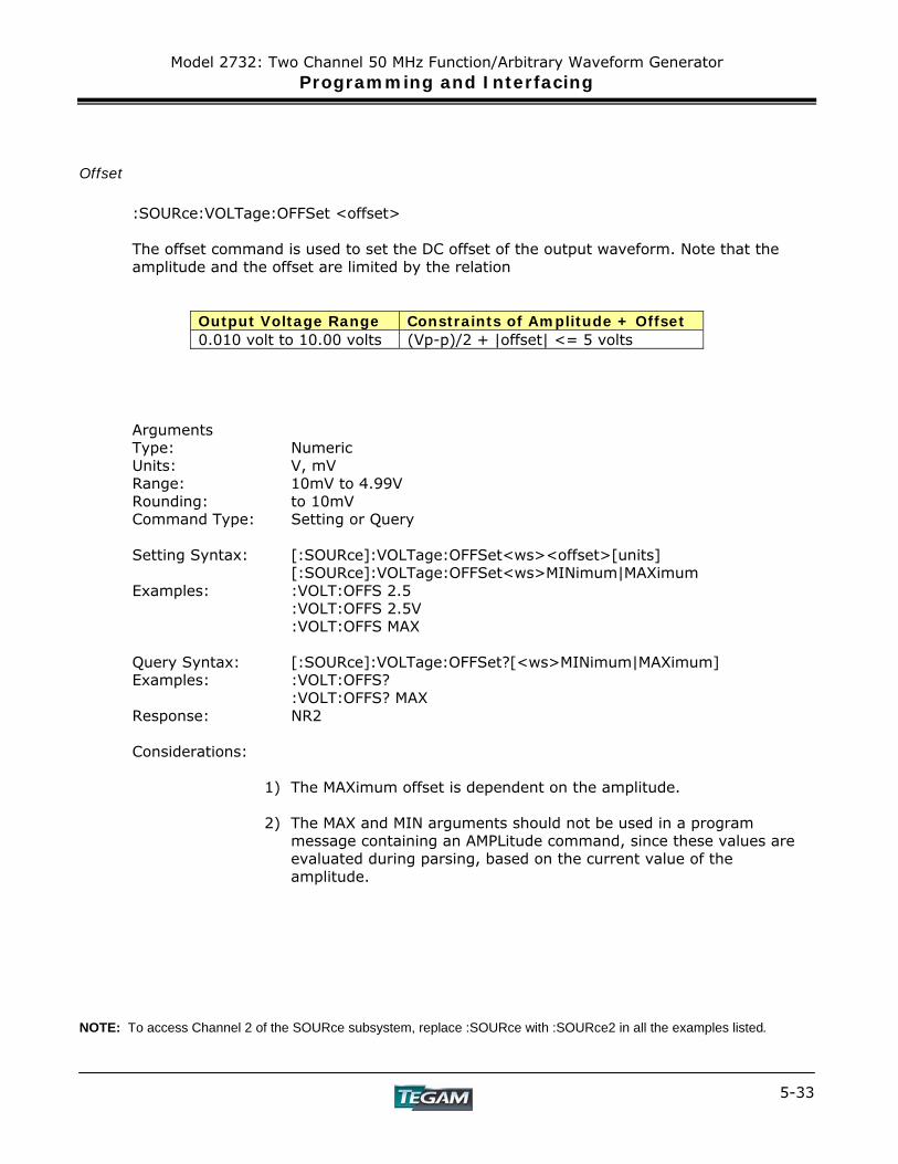
Model 2732: Two Channel 50 MHz Function/Arbitrary Waveform Generator Programming and Interfacing
5-33
Offset
:SOURce:VOLTage:OFFSet <offset>
The offset command is used to set the DC offset of the output waveform. Note that the amplitude and the offset are limited by the relation
Output Voltage Range Constraints of Amplitude + Offset 0.010 volt to 10.00 volts (Vp-p)/2 + |offset| <= 5 volts
Arguments Type: Numeric Units: V, mV Range: 10mV to 4.99V Rounding: to 10mV Command Type: Setting or Query Setting Syntax: [:SOURce]:VOLTage:OFFSet<ws><offset>[units]
[:SOURce]:VOLTage:OFFSet<ws>MINimum|MAXimum Examples: :VOLT:OFFS 2.5
:VOLT:OFFS 2.5V :VOLT:OFFS MAX
Query Syntax: [:SOURce]:VOLTage:OFFSet?[<ws>MINimum|MAXimum] Examples: :VOLT:OFFS?
:VOLT:OFFS? MAX Response: NR2
Considerations:
1) The MAXimum offset is dependent on the amplitude.
2) The MAX and MIN arguments should not be used in a program
message containing an AMPLitude command, since these values are evaluated during parsing, based on the current value of the amplitude.
NOTE: To access Channel 2 of the SOURce subsystem, replace :SOURce with :SOURce2 in all the examples listed.
Model 2732: Two Channel 50 MHz Function/Arbitrary Waveform Generator Programming and Interfacing
5-34
Clock Reference Source
:SOURce:REFerence:SOURce <clock source>
This command is used to select the source of the arbitrary waveform clock. This clock sets the arbitrary waveform point rate.
Arguments Type: Character Options: INTernal, EXTernal Command Type: Setting or Query Setting Syntax: [:SOURce]: REFerence<ws><option> Examples: :REF INT :SOUR:REF EXT Query Syntax: [:SOURce]: REFerence?
Response: INT|EXT
Function
:SOURce:FUNCtion [:SHAPe] The function command is used to set the type of waveform to be generated by the instrument.
Command Type: Setting or Query Setting Syntax: [:SOURce]:FUNCtion[:SHAPe]<WS><OPTION> Examples: :FUNC SIN
:FUNC ARB Query Syntax: [:SOURce]:FUNCtion[:SHAPe]? Examples: :FUNC? Response: SIN|TRI|SQU|ARB|PUL Considerations: The following functions are available:
SINusoid,SQUare, TRIangle, ARBitrary, PULse NOTE: To access Channel 2 of the SOURce subsystem, replace :SOURce with :SOURce2 in all the examples listed.
Model 2732: Two Channel 50 MHz Function/Arbitrary Waveform Generator Programming and Interfacing
5-35
Point Rate
:SOURce:PRATe <point rate> This command is used to set the point rate. It is coupled with the frequency of the waveform by the relation
Frequency = 1/(Point Rate * Wavelength) Thus changing the point rate will result in a change in frequency.
Arguments Type: Numeric Units: S, mS, uS, nS Range: 8 nS to 100S Rounding: To 4 digits Command Type: Setting or Query Setting Syntax: :SOURce:PRATe<ws><point rate>[units]
:SOURce:PRATe<ws>MINimum|MAXimum Examples: :ARB:PRAT 500NS Query Syntax: :ARBitrary:PRATe?[<ws>MINimum|MAXimum] Response: NR3
NOTE: To access Channel 2 of the SOURce subsystem, replace :SOURce with :SOURce2 in all the examples listed.

Model 2732: Two Channel 50 MHz Function/Arbitrary Waveform Generator Programming and Interfacing
5-36
AM Modulation The following commands control the AM modulation:
AM STATe
This command activates or deactivates AM modulation: Arguments Type: Boolean Command Type: Setting or Query Setting Syntax: [:SOURce:]AM [:STATe]<ws>ON|1|OFF|0 Examples: :SOURce:AM :STAT ON
AM OFF Query Syntax: [:SOURce:]AM[:STATe]? Response: 0|1
AM DEPTh
This command sets the AM modulation depth in % Arguments Type: Numeric Units: none (implied %) Range: 0 to 100 Rounding: to integer Command Type: Setting or Query Setting Syntax: :SOURce:AM:DEPTh<ws><percent depth>
:SOURce:AM:DEPTh<ws>MINimum|MAXimum Examples: AM:DEPTh 50 Query Syntax: AM:DEPTh?[<ws>MINimum|MAXimum] Response: NR3
NOTE: To access Channel 2 of the SOURce subsystem, replace :SOURce with: SOURce2 in all the examples listed.

Model 2732: Two Channel 50 MHz Function/Arbitrary Waveform Generator Programming and Interfacing
5-37
AM SHAPe
This command selects the AM modulating waveform shape Arguments Type: Character Options: SINusoid, TRIangle, SQUare Command Type: Setting or Query Setting Syntax: [:SOURce:]AM:SHAPe<ws><SIN|TRI|SQU>
Examples: [:SOURce:]AM:SHPE SIN AM:SHAPE TRI
Query Syntax: [:SOURce:]AM:SHAPe? Response: SIN|TRI|SQU
AM FREQuency
This command sets the AM modulating waveform frequency Arguments Type: Numeric. Units: MHz, KHz, Hz (default) Range: Fmax = 20 KHz
Fmin = 0.01 Hz Rounding: The value is rounded to 4 digits. Command Type: Setting or Query Setting Syntax: [:SOURce:]AM:FREQuency<ws><frequency>[units]
[:SOURce:]AM:FREQuency<ws>MINimum|MAXimum Examples: AM:FREQ 5KHZ
AM:FREQ 5E3 AM:FREQ MAXIMUM AM:FREQ MIN
Query Syntax: [:SOURce:]AM:FREQuency?[<ws>MAXimum|MINimum] Examples: AM:FREQ?
AM:FREQ? MAX Response: NR3
NOTE: To access Channel 2 of the SOURce subsystem, replace :SOURce with :SOURce2 in all the examples listed.
Model 2732: Two Channel 50 MHz Function/Arbitrary Waveform Generator Programming and Interfacing
5-38
AM SOURce
This command selects the AM modulation source as either internal (then the above settings are effective) or external (and then the external waveform determines depth, shape and frequency of modulation).
Arguments Type: Character Options: INTernal, EXTernal Command Type: Setting or Query Setting Syntax: [:SOURce:] AM:SOURce<ws><option> Examples: AM:SOUR INT
AM:SOUR EXT Query Syntax: [:SOURce]:AM:SOURce? Response: INT|EXT
NOTE: To access Channel 2 of the SOURce subsystem, replace :SOURce with :SOURce2 in all the examples listed.
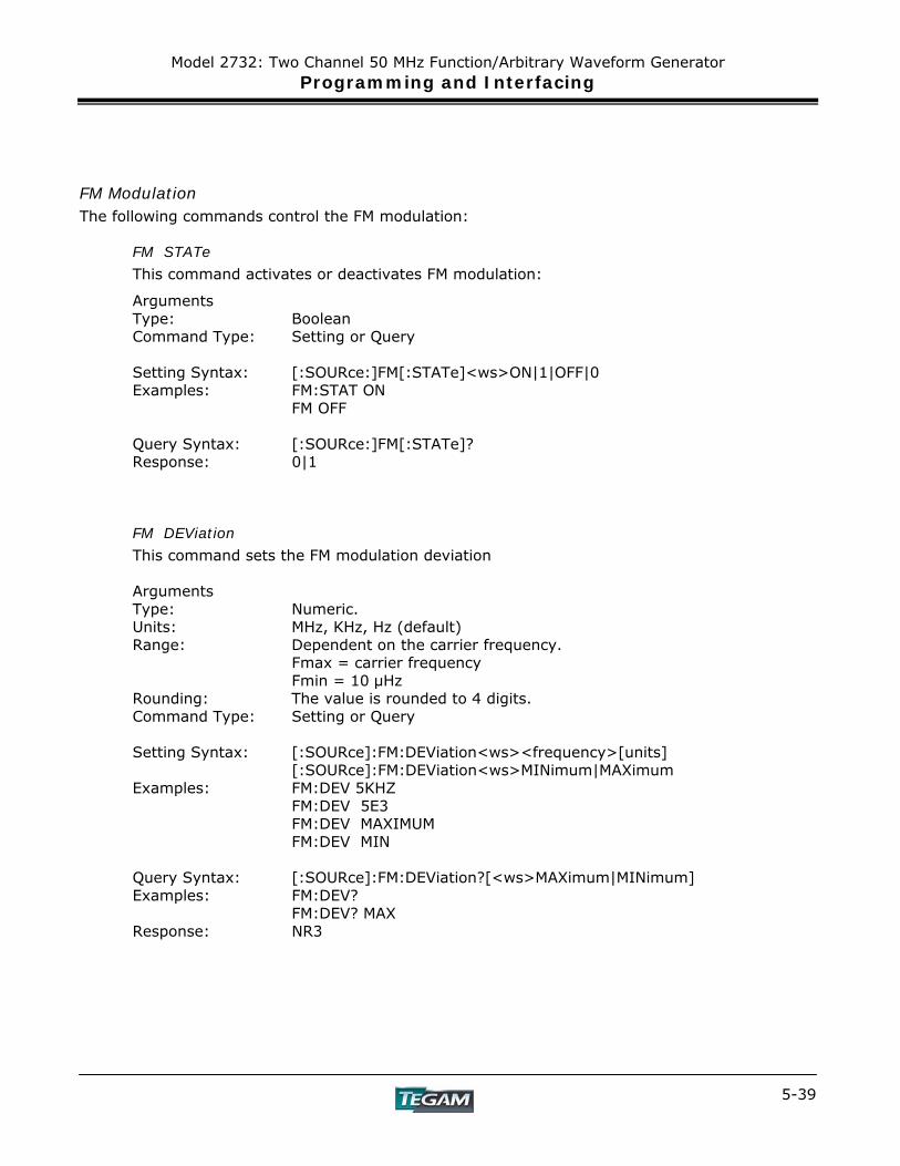
Model 2732: Two Channel 50 MHz Function/Arbitrary Waveform Generator Programming and Interfacing
5-39
FM Modulation
The following commands control the FM modulation:
FM STATe
This command activates or deactivates FM modulation:
Arguments Type: Boolean Command Type: Setting or Query Setting Syntax: [:SOURce:]FM[:STATe]<ws>ON|1|OFF|0 Examples: FM:STAT ON
FM OFF Query Syntax: [:SOURce:]FM[:STATe]? Response: 0|1
FM DEViation
This command sets the FM modulation deviation Arguments Type: Numeric. Units: MHz, KHz, Hz (default) Range: Dependent on the carrier frequency.
Fmax = carrier frequency Fmin = 10 μHz
Rounding: The value is rounded to 4 digits. Command Type: Setting or Query Setting Syntax: [:SOURce]:FM:DEViation<ws><frequency>[units]
[:SOURce]:FM:DEViation<ws>MINimum|MAXimum Examples: FM:DEV 5KHZ
FM:DEV 5E3 FM:DEV MAXIMUM FM:DEV MIN
Query Syntax: [:SOURce]:FM:DEViation?[<ws>MAXimum|MINimum] Examples: FM:DEV?
FM:DEV? MAX Response: NR3

Model 2732: Two Channel 50 MHz Function/Arbitrary Waveform Generator Programming and Interfacing
5-40
NOTE: To access Channel 2 of the SOURce subsystem, replace :SOURce with :SOURce2 in all the examples listed.
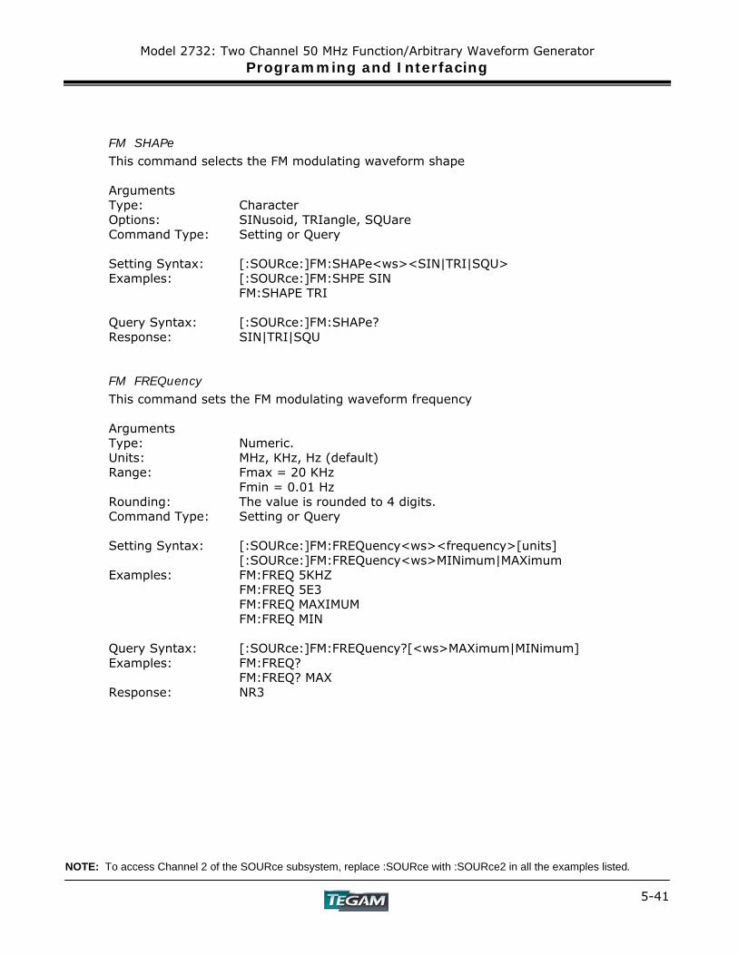
Model 2732: Two Channel 50 MHz Function/Arbitrary Waveform Generator Programming and Interfacing
5-41
FM SHAPe
This command selects the FM modulating waveform shape Arguments Type: Character Options: SINusoid, TRIangle, SQUare Command Type: Setting or Query Setting Syntax: [:SOURce:]FM:SHAPe<ws><SIN|TRI|SQU>
Examples: [:SOURce:]FM:SHPE SIN FM:SHAPE TRI
Query Syntax: [:SOURce:]FM:SHAPe? Response: SIN|TRI|SQU
FM FREQuency
This command sets the FM modulating waveform frequency Arguments Type: Numeric. Units: MHz, KHz, Hz (default) Range: Fmax = 20 KHz
Fmin = 0.01 Hz Rounding: The value is rounded to 4 digits. Command Type: Setting or Query Setting Syntax: [:SOURce:]FM:FREQuency<ws><frequency>[units]
[:SOURce:]FM:FREQuency<ws>MINimum|MAXimum Examples: FM:FREQ 5KHZ
FM:FREQ 5E3 FM:FREQ MAXIMUM FM:FREQ MIN
Query Syntax: [:SOURce:]FM:FREQuency?[<ws>MAXimum|MINimum] Examples: FM:FREQ?
FM:FREQ? MAX Response: NR3
NOTE: To access Channel 2 of the SOURce subsystem, replace :SOURce with :SOURce2 in all the examples listed.
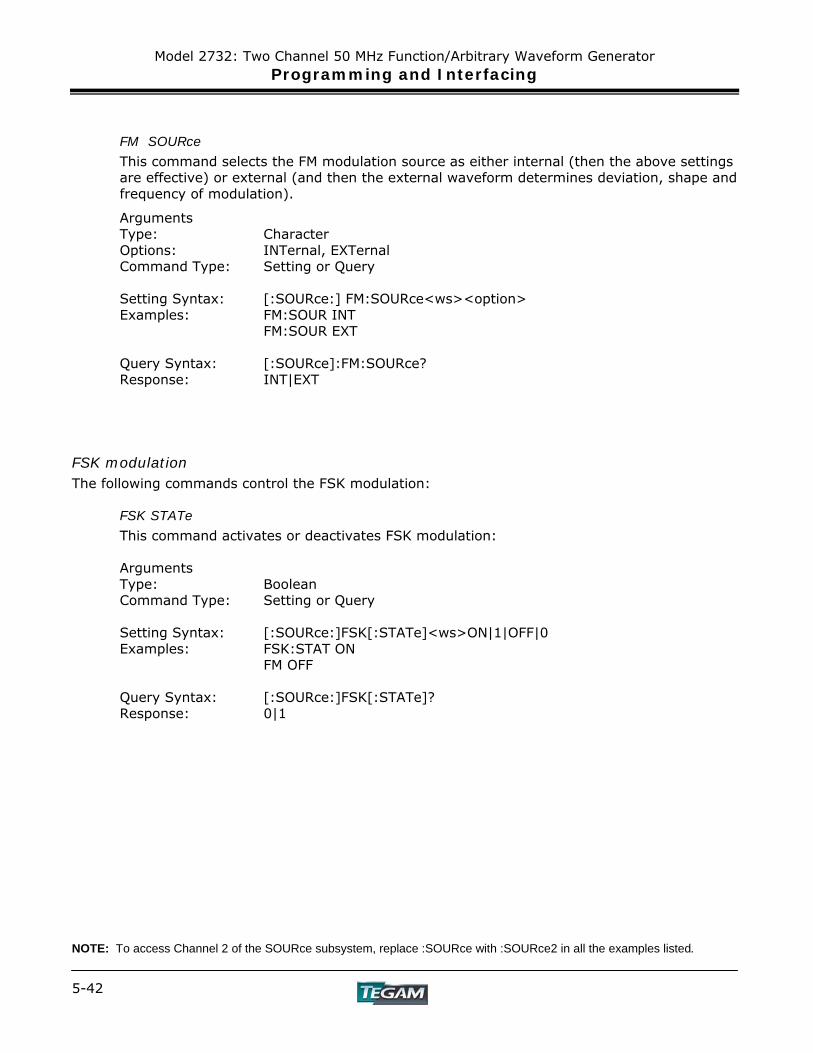
Model 2732: Two Channel 50 MHz Function/Arbitrary Waveform Generator Programming and Interfacing
5-42
FM SOURce
This command selects the FM modulation source as either internal (then the above settings are effective) or external (and then the external waveform determines deviation, shape and frequency of modulation).
Arguments Type: Character Options: INTernal, EXTernal Command Type: Setting or Query Setting Syntax: [:SOURce:] FM:SOURce<ws><option> Examples: FM:SOUR INT
FM:SOUR EXT Query Syntax: [:SOURce]:FM:SOURce? Response: INT|EXT
FSK modulation The following commands control the FSK modulation:
FSK STATe
This command activates or deactivates FSK modulation: Arguments Type: Boolean Command Type: Setting or Query Setting Syntax: [:SOURce:]FSK[:STATe]<ws>ON|1|OFF|0 Examples: FSK:STAT ON
FM OFF Query Syntax: [:SOURce:]FSK[:STATe]? Response: 0|1
NOTE: To access Channel 2 of the SOURce subsystem, replace :SOURce with :SOURce2 in all the examples listed.
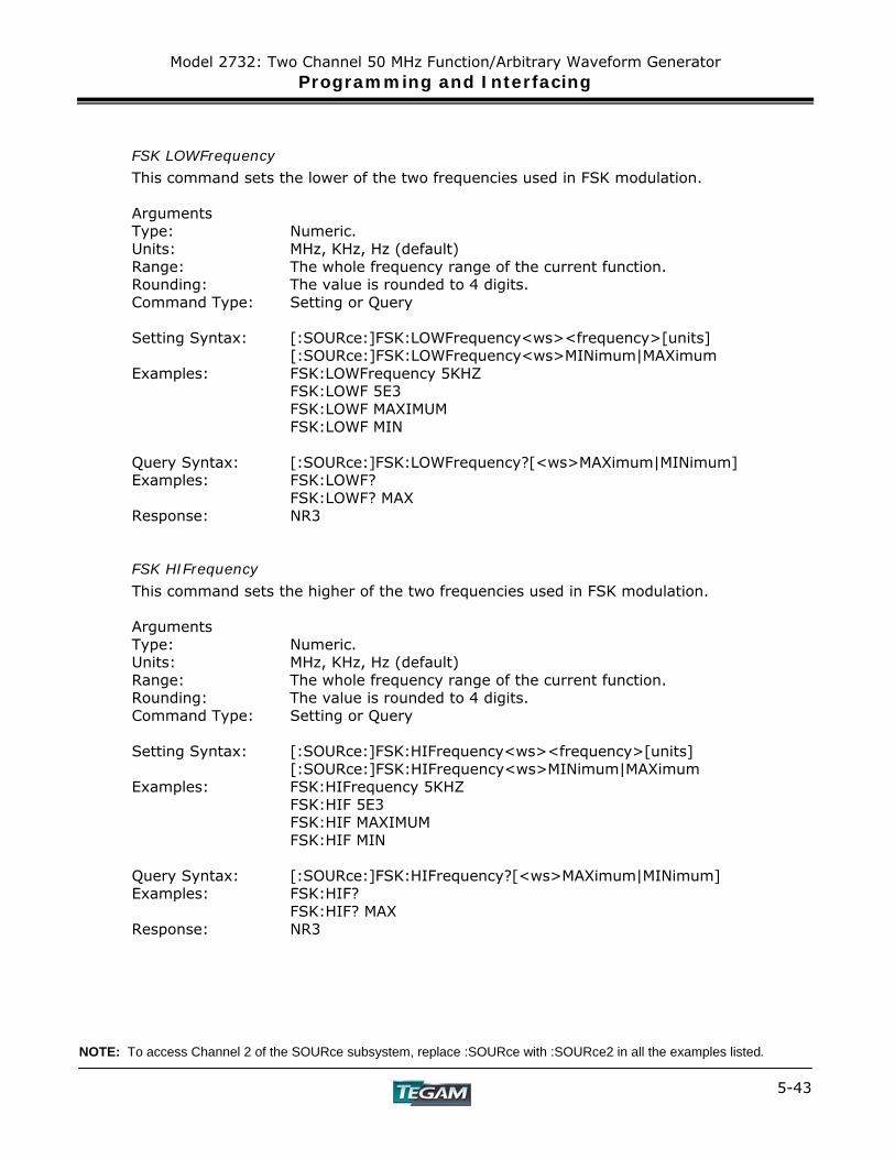
Model 2732: Two Channel 50 MHz Function/Arbitrary Waveform Generator Programming and Interfacing
5-43
FSK LOWFrequency
This command sets the lower of the two frequencies used in FSK modulation. Arguments Type: Numeric. Units: MHz, KHz, Hz (default) Range: The whole frequency range of the current function.
Rounding: The value is rounded to 4 digits. Command Type: Setting or Query Setting Syntax: [:SOURce:]FSK:LOWFrequency<ws><frequency>[units]
[:SOURce:]FSK:LOWFrequency<ws>MINimum|MAXimum Examples: FSK:LOWFrequency 5KHZ
FSK:LOWF 5E3 FSK:LOWF MAXIMUM FSK:LOWF MIN
Query Syntax: [:SOURce:]FSK:LOWFrequency?[<ws>MAXimum|MINimum] Examples: FSK:LOWF?
FSK:LOWF? MAX Response: NR3
FSK HIFrequency
This command sets the higher of the two frequencies used in FSK modulation. Arguments Type: Numeric. Units: MHz, KHz, Hz (default) Range: The whole frequency range of the current function. Rounding: The value is rounded to 4 digits. Command Type: Setting or Query Setting Syntax: [:SOURce:]FSK:HIFrequency<ws><frequency>[units]
[:SOURce:]FSK:HIFrequency<ws>MINimum|MAXimum Examples: FSK:HIFrequency 5KHZ
FSK:HIF 5E3 FSK:HIF MAXIMUM FSK:HIF MIN
Query Syntax: [:SOURce:]FSK:HIFrequency?[<ws>MAXimum|MINimum] Examples: FSK:HIF?
FSK:HIF? MAX Response: NR3
NOTE: To access Channel 2 of the SOURce subsystem, replace :SOURce with :SOURce2 in all the examples listed.
Model 2732: Two Channel 50 MHz Function/Arbitrary Waveform Generator Programming and Interfacing
5-44
FSK RATE
This command sets the rate of switching between the two frequencies of the modulation. Arguments Type: Numeric. Units: MHz, KHz, Hz (default) Range: Fmax = 1MHz
Fmin = 0.01Hz Rounding: The value is rounded to 4 digits. Command Type: Setting or Query Setting Syntax: [:SOURce:]:FSK:RATE<ws><frequency>[units]
[:SOURce:]:FSK:RATE <ws>MINimum|MAXimum Examples: FSK:RATE 5KHZ
FSK:RATE 5E3 FSK:RATE MAXIMUM FSK:RATE MIN
Query Syntax: [:SOURce]:FSK:RATE ?[<ws>MAXimum|MINimum] Examples: FSK:RATE ?
FSK:RATE ? MAX Response: NR3
FSK SOURce
This command selects the FSK modulation source as either internal (then the above settings are effective) or external (and then the external waveform determines the frequency of modulation).
Arguments Type: Character Options: INTernal, EXTernal Command Type: Setting or Query Setting Syntax: [:SOURce:] FSK:SOURce<ws><option> Examples: FSK:SOUR INT
FSK:SOUR EXT Query Syntax: [:SOURce]:FSK:SOURce? Response: INT|EXT
NOTE: To access Channel 2 of the SOURce subsystem, replace :SOURce with :SOURce2 in all the examples listed.

Model 2732: Two Channel 50 MHz Function/Arbitrary Waveform Generator Programming and Interfacing
5-45
Sweep Control
The following commands control the sweep functionality:
Sweep STATe
This command activates or deactivates sweep:
Arguments Type: Boolean Command Type: Setting or Query Setting Syntax: [:SOURce:]SWEEP[:STATe]<ws>ON|1|OFF|0 Examples: SWEEP:STAT ON
SWEEP OFF Query Syntax: [:SOURce:]SWEEP[:STATe]? Response: 0|1
Sweep SPACing
This command sets the sweep spacing as either LINear or LOGarithmic:
Arguments Type: Character Options: LINear,LOGarithmic Command Type: Setting or Query Setting Syntax: [:SOURce:]SWEEP:SPACing<ws><LIN|LOG>
Examples: [:SOURce:] SWEEP:SPACing LIN SWEEP:SPAC LOG
Query Syntax: [:SOURce:] SWEEP:SPACing ? Response: LIN|LOG
NOTE: To access Channel 2 of the SOURce subsystem, replace :SOURce with :SOURce2 in all the examples listed.
Model 2732: Two Channel 50 MHz Function/Arbitrary Waveform Generator Programming and Interfacing
5-46
Sweep TIME This command sets the time for one complete sweep:
Arguments Type: Numeric Units: S, mS, uS, nS Range: 10mS to 500S Rounding: to 4 digits Command Type: Setting or Query Setting Syntax: [:SOURce:]SWEEP:TIME<ws><time>[units]
[:SOURce:]SWEEP:TIME<ws>MINimum|MAXimum Examples: SWEEP:TIME 50MS Query Syntax: [:SOURce:]SWEEP:TIME?[<ws>MINimum|MAXimum] Response: NR3
Sweep STARt
This command sets the start frequency of the sweep:
Arguments Type: Numeric. Units: MHz, KHz, Hz (default) Range: Dependent on the frequency range of the current function.
Rounding: The value is rounded to 4 digits. Command Type: Setting or Query Setting Syntax: [:SOURce:]SWEEP:STARt<ws><frequency>[units]
[:SOURce:]SWEEP:STARt<ws>MINimum|MAXimum Examples: SWEEP:STARt 5KHZ
SWEEP:STARt 5E3 SWEEP:STARt MAXIMUM SWEEP:STARt MIN
Query Syntax: [:SOURce:]SWEEP:STARt?[<ws>MAXimum|MINimum] Examples: SWEEP:STARt ?
SWEEP:STARt ? MAX Response: NR3
NOTE: To access Channel 2 of the SOURce subsystem, replace :SOURce with :SOURce2 in all the examples listed.
Model 2732: Two Channel 50 MHz Function/Arbitrary Waveform Generator Programming and Interfacing
5-47
Sweep STOP
This command sets the stop frequency of the sweep:
Arguments Type: Numeric. Units: MHz, KHz, Hz (default) Range: Dependent on the frequency range of the current function. Rounding: The value is rounded to 4 digits. Command Type: Setting or Query Setting Syntax: [:SOURce:]SWEEP:STOP<ws><frequency>[units]
[:SOURce:]SWEEP:STOP<ws>MINimum|MAXimum Examples: SWEEP:STOP 5KHZ
SWEEP:STOP 5E3 SWEEP:STOP MAXIMUM SWEEP:STOP MIN
Query Syntax: [:SOURce:]SWEEP:STOP?[<ws>MAXimum|MINimum] Examples: SWEEP:STOP ?
SWEEP:STOP ? MAX Response: NR3

Model 2732: Two Channel 50 MHz Function/Arbitrary Waveform Generator Programming and Interfacing
5-48
NOTE: To access Channel 2 of the SOURce subsystem, replace :SOURce with :SOURce2 in all the examples listed.
Model 2732: Two Channel 50 MHz Function/Arbitrary Waveform Generator Programming and Interfacing
5-49
Phase Control
PHASe adjust
This command controls the phase adjustment Arguments Type: Numeric Units: one (degrees implied) Range: -180 to +180 (other values converted to this range) Rounding: to integer Command Type: Setting or Query Setting Syntax: [:SOURce:]PHASe<ws><phase>
[:SOURce:]PHASe<ws>MINimum|MAXimum Examples: [:SOURce:]PHASe 500NS Query Syntax: [:SOURce:]PHASe?[<ws>MINimum|MAXimum] Response: NR3
PULSe setting The following commands control the pulse function: Note the following pulse constraints:
Width < Period Width ≥ Period * 1 E-6 Width ≥ (Rise+Fall) Period > Width + (Rise + Fall) Rise ≥ Width / 100 (or Rise = .01 μs) Fall ≥ Width / 100 (or Fall = .01 μs) Rise > Period / 100,000 (or Rise = .01 µs) Fall > Period / 100,000 (or Fall = .01 µs)
PULSe PERiod
This command sets the pulse period to the specified value. NOTE: This also sets the pulse frequency. Arguments Type: Numeric Units: S, ms, us, ns Range: 40 ns-2000 s Rounding: 4 digits Command Type: Setting or Query Setting Syntax: [:SOURce:] PULse: PERiod <ws><value>
[:SOURce:] PULse: PERiod <ws>MINimum|MAXimum Examples: [:SOURce:] PULse: PERiod 500NS Query Syntax: [:SOURce:] PULse: PERiod?[<ws>MINimum|MAXimum] Response: NR3
NOTE: To access Channel 2 of the SOURce subsystem, replace :SOURce with :SOURce2 in all the examples listed.
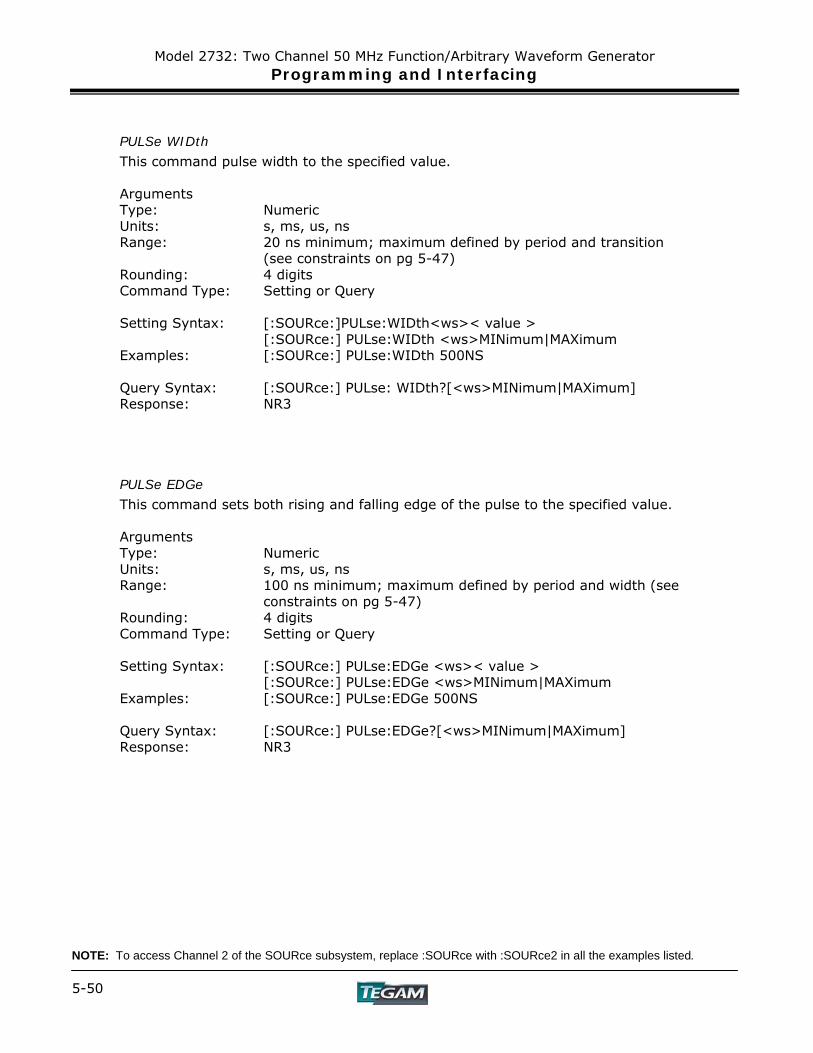
Model 2732: Two Channel 50 MHz Function/Arbitrary Waveform Generator Programming and Interfacing
5-50
PULSe WIDth
This command pulse width to the specified value. Arguments Type: Numeric Units: s, ms, us, ns Range: 20 ns minimum; maximum defined by period and transition
(see constraints on pg 5-47) Rounding: 4 digits Command Type: Setting or Query Setting Syntax: [:SOURce:]PULse:WIDth<ws>< value >
[:SOURce:] PULse:WIDth <ws>MINimum|MAXimum Examples: [:SOURce:] PULse:WIDth 500NS Query Syntax: [:SOURce:] PULse: WIDth?[<ws>MINimum|MAXimum] Response: NR3
PULSe EDGe
This command sets both rising and falling edge of the pulse to the specified value. Arguments Type: Numeric Units: s, ms, us, ns Range: 100 ns minimum; maximum defined by period and width (see
constraints on pg 5-47) Rounding: 4 digits Command Type: Setting or Query Setting Syntax: [:SOURce:] PULse:EDGe <ws>< value >
[:SOURce:] PULse:EDGe <ws>MINimum|MAXimum Examples: [:SOURce:] PULse:EDGe 500NS Query Syntax: [:SOURce:] PULse:EDGe?[<ws>MINimum|MAXimum] Response: NR3
NOTE: To access Channel 2 of the SOURce subsystem, replace :SOURce with :SOURce2 in all the examples listed.
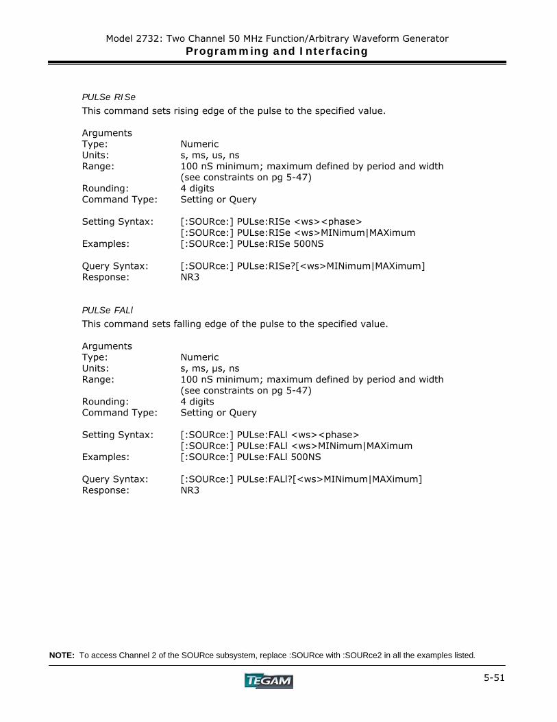
Model 2732: Two Channel 50 MHz Function/Arbitrary Waveform Generator Programming and Interfacing
5-51
PULSe RISe
This command sets rising edge of the pulse to the specified value.
Arguments Type: Numeric Units: s, ms, us, ns Range: 100 nS minimum; maximum defined by period and width
(see constraints on pg 5-47) Rounding: 4 digits Command Type: Setting or Query Setting Syntax: [:SOURce:] PULse:RISe <ws><phase>
[:SOURce:] PULse:RISe <ws>MINimum|MAXimum Examples: [:SOURce:] PULse:RISe 500NS Query Syntax: [:SOURce:] PULse:RISe?[<ws>MINimum|MAXimum] Response: NR3
PULSe FALl
This command sets falling edge of the pulse to the specified value. Arguments Type: Numeric Units: s, ms, μs, ns Range: 100 nS minimum; maximum defined by period and width
(see constraints on pg 5-47) Rounding: 4 digits Command Type: Setting or Query Setting Syntax: [:SOURce:] PULse:FALl <ws><phase>
[:SOURce:] PULse:FALl <ws>MINimum|MAXimum Examples: [:SOURce:] PULse:FALl 500NS Query Syntax: [:SOURce:] PULse:FALl?[<ws>MINimum|MAXimum] Response: NR3
NOTE: To access Channel 2 of the SOURce subsystem, replace :SOURce with :SOURce2 in all the examples listed.
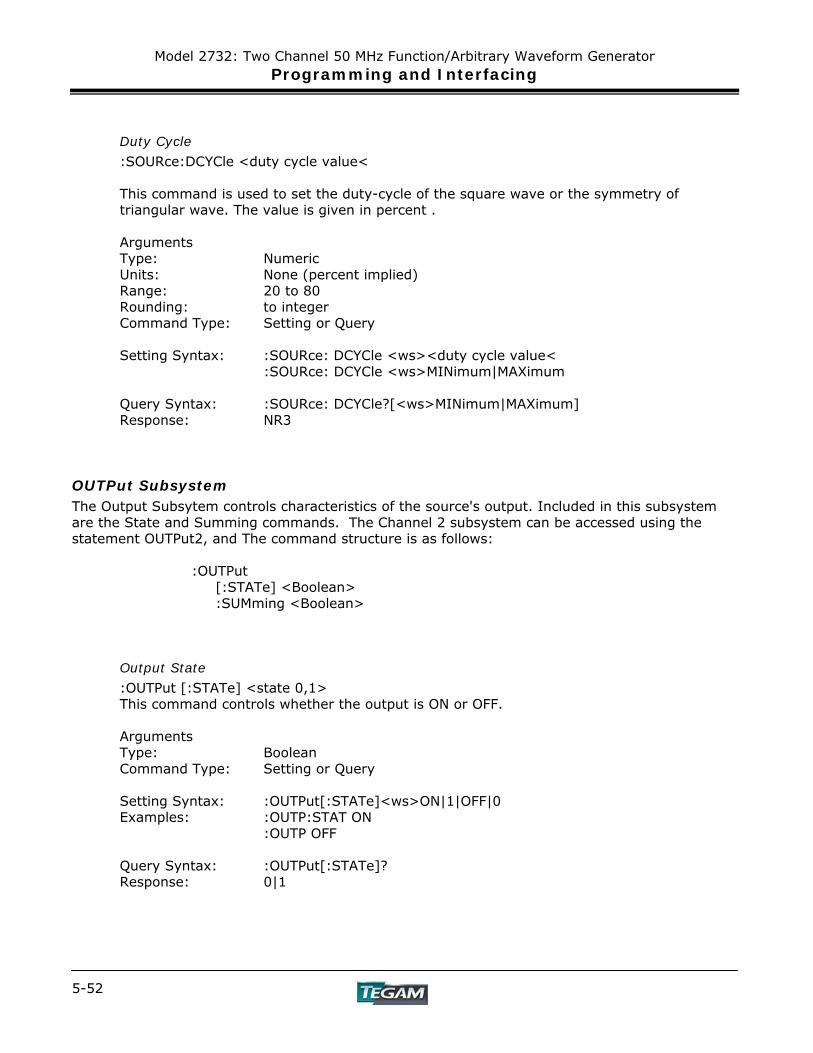
Model 2732: Two Channel 50 MHz Function/Arbitrary Waveform Generator Programming and Interfacing
5-52
Duty Cycle
:SOURce:DCYCle <duty cycle value< This command is used to set the duty-cycle of the square wave or the symmetry of triangular wave. The value is given in percent . Arguments Type: Numeric Units: None (percent implied) Range: 20 to 80 Rounding: to integer Command Type: Setting or Query Setting Syntax: :SOURce: DCYCle <ws><duty cycle value<
:SOURce: DCYCle <ws>MINimum|MAXimum Query Syntax: :SOURce: DCYCle?[<ws>MINimum|MAXimum] Response: NR3
OUTPut Subsystem The Output Subsytem controls characteristics of the source's output. Included in this subsystem are the State and Summing commands. The Channel 2 subsystem can be accessed using the statement OUTPut2, and The command structure is as follows: :OUTPut [:STATe] <Boolean> :SUMming <Boolean>
Output State
:OUTPut [:STATe] <state 0,1> This command controls whether the output is ON or OFF.
Arguments Type: Boolean Command Type: Setting or Query Setting Syntax: :OUTPut[:STATe]<ws>ON|1|OFF|0 Examples: :OUTP:STAT ON
:OUTP OFF Query Syntax: :OUTPut[:STATe]? Response: 0|1

Model 2732: Two Channel 50 MHz Function/Arbitrary Waveform Generator Programming and Interfacing
5-53
NOTE: To access Channel 2 of the OUTPut subsystem, replace :OUTPut with :OUTPut2.
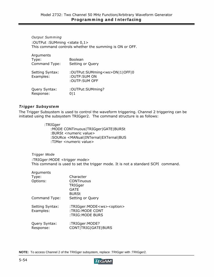
Model 2732: Two Channel 50 MHz Function/Arbitrary Waveform Generator Programming and Interfacing
5-54
Output Summing
:OUTPut :SUMming <state 0,1> This command controls whether the summing is ON or OFF.
Arguments Type: Boolean Command Type: Setting or Query Setting Syntax: :OUTPut:SUMming<ws>ON|1|OFF|0 Examples: :OUTP:SUM ON
:OUTP:SUM OFF Query Syntax: :OUTPut:SUMming? Response: 0|1
Trigger Subsystem The Trigger Subsystem is used to control the waveform triggering. Channel 2 triggering can be initiated using the subsystem TRIGger2. The command structure is as follows: :TRIGger :MODE CONTinuous|TRIGger|GATE|BURSt :BURSt <numeric value> :SOURce <MANual|INTernal|EXTernal|BUS :TIMer <numeric value>
Trigger Mode
:TRIGger:MODE <trigger mode> This command is used to set the trigger mode. It is not a standard SCPI command.
Arguments Type: Character Options: CONTinuous
TRIGger GATE BURSt
Command Type: Setting or Query Setting Syntax: :TRIGger:MODE<ws><option> Examples: :TRIG:MODE CONT
:TRIG:MODE BURS Query Syntax: :TRIGger:MODE? Response: CONT|TRIG|GATE|BURS
NOTE: To access Channel 2 of the TRIGger subsystem, replace :TRIGger with :TRIGger2.
Model 2732: Two Channel 50 MHz Function/Arbitrary Waveform Generator Programming and Interfacing
5-55
Trigger Source
:TRIGger:SOURce <trigger source>
This command is used to select the trigger source, for use in the Trigger, Gate and Burst trigger modes.
Arguments Type: Character Options: MANual - Front panel MAN key
BUS - GPIB trigger (GET or *TRG) INTernal - Internal trigger EXTernal - External trigger
Command Type: Setting or Query Setting Syntax: :TRIGger:SOURce<ws><option> Examples: :TRIG:SOUR BUS
:TRIG:SOUR INT Query Syntax: :TRIGger:SOURce? Response: MAN|BUS|INT|EXT
Burst Count
:TRIGger:BURSt <burst count> Used to set the number of cycles to be output in the BURST mode. It is not a standard SCPI command.
Arguments Type: Numeric Range: 1 to 999999 Rounding: to integer value Command Type: Setting or Query Setting Syntax :TRIGger:BURSt<ws><value> Examples :TRIG:BURS 100
:TRIG:BURS MAXIMUM Query Syntax: :TRIGger:BURSt?[<ws>MAXimum|MINimum] Response: NR1 Examples: :TRIG:BURST?
:TRIG:BURS? MAX NOTE: To access Channel 2 of the TRIGger subsystem, replace :TRIGger with :TRIGger2.
Model 2732: Two Channel 50 MHz Function/Arbitrary Waveform Generator Programming and Interfacing
5-56
Internal Trigger Rate
:TRIGger:TIMer <trigger rate> Sets the rate of the internal trigger.
Arguments Type: Numeric Units: s, ms, us, ns Range: 1E-6S to 100S Rounding: to 4 digits Command Type: Setting or Query Setting Syntax: :TRIGger:TIMer<ws><value>[units]
:TRIGger:TIMer<ws>MINimum|MAXimum Examples: :TRIG:TIM 10E-6
:TRIG:TIM MIN Query Syntax: :TRIGger:TIMer?[<ws>MINimum|MAXimum] Response: NR3 Examples: :TRIG:TIM?
:TRIG:TIM? MIN NOTE: To access Channel 2 of the TRIGger subsystem, replace :TRIGger with :TRIGger2
Arbitrary Subsystem The Arbitrary subsystem is not part of the SCPI standard. It was developed to suit the needs of the instrument. Following the same mnemonics of earlier subsystems, Channel 2 arbitrary subsystems can be accessed using the ARBitrary2 command. Within this subsystem are found commands to:
1) Control the point rate, start address, wavelength, marker address, and
synchronization pulse address; 2) Set values of the arbitrary waveform, either discretely or using predefined, copy
or draw functions;
3) Protect an area of waveform memory;
4) Set the state of the automatic update and increment features;
5) Update the waveform.
NOTE: To access Channel 2 of the ARBitrary subsystem, replace :ARBitrary with :ARBitrary2 in all the examples listed.
Model 2732: Two Channel 50 MHz Function/Arbitrary Waveform Generator Programming and Interfacing
5-57
The following shows the structure of the ARBitrary subsystem:
:ARBitrary :PRATe <numeric value> :ADDRess <numeric value> :DATA <numeric value>|<arbitrary block> :DRAW <numeric value>,<numeric value> :CLEar <numeric value>,<numeric value> :COPY <NRf>,<NRf>,<NRf> :PROTect [:RANGe] <numeric value>,<numeric value> :STATe <Boolean> :PREDefined <shape>,<start address>,<length>,<scale> :STARt <numeric value> :LENGth <numeric value> :MARKer [:ADDRess] <numeric value> :STATe <Boolean> :LENGth <numeric value> :SAVe
Point Execution Rate
ARBitrary:PRATe <point rate> This command is used to set the point execution rate. It is coupled with the frequency of the waveform by the relation:
Frequency = 1/(Point Rate * Wavelength) Thus changing the point rate will result in a change in frequency.
Arguments Type: Numeric Units: s, ms, us, ns Range: 8ns to 100s Rounding: to 4 digits Command Type: Setting or Query Setting Syntax: :ARBitrary:PRATe<ws><point rate>[units]
:ARBitrary:PRATe<ws>MINimum|MAXimum Examples: :ARB:PRAT 100NS Query Syntax: :ARBitrary:PRATe?[<ws>MINimum|MAXimum] Response: NR3
NOTE: To access Channel 2 of the ARBitrary subsystem, replace :ARBitrary with :ARBitrary2 in all the examples listed.
Model 2732: Two Channel 50 MHz Function/Arbitrary Waveform Generator Programming and Interfacing
5-58
Address
:ARBitrary:ADDRess <address> This command sets the current address of the waveform. It is used to determine to where arbitrary data are to be written.
Arguments Type: Numeric Range: 1 to 4,000,000 Rounding: to integer value Command Type: Setting or Query Setting Syntax: :ARBitrary:ADDRess<ws><address>
:ARBitrary:ADDRess<ws>MINimum|MAXimum Examples: :ARB:ADDR 100 Query Syntax: :ARBitrary:ADDRess?[<ws>MINimum|MAXimum] Response: NR1
Data
:ARBitrary:DATA <data> This command is used to set the values of the waveform.
Arguments Type: Numeric.
Definite form arbitrary block. Indefinite form arbitrary block
Numeric Range: -8191 to 8191 ASCII Rounding: Must be round to a whole integer Binary Range: 001H to 3FFFH BINARY Command Type: Setting or Query Setting Syntax: Numeric: :ARBitrary:DATA<ws><numeric>{[,<numeric]} Example :ARB:DATA 100,200,1000,2000,-2000 Arbitrary Block: :ARBitrary:DATA<ws>#<arb block data>
See the section on Block Transfer Examples
Definite: :ARB:DATA #14\x8\x64\x8\xC8 '\x' indicates that the values are Hexadecimal. Indefinite: :ARB:DATA #0\x8\x64\x8\xc8\xa^EOI
Query Syntax: :ARBitrary:DATA?<ws><number of points>, BINary|ASCii Response: Using the BINary option, data is returned in indefinite arbitrary block
form. Using the ASCii option, data is returned in decimal numeric form.
NOTE: To access Channel 2 of the ARBitrary subsystem, replace :ARBitrary with :ARBitrary2 in all the examples listed.
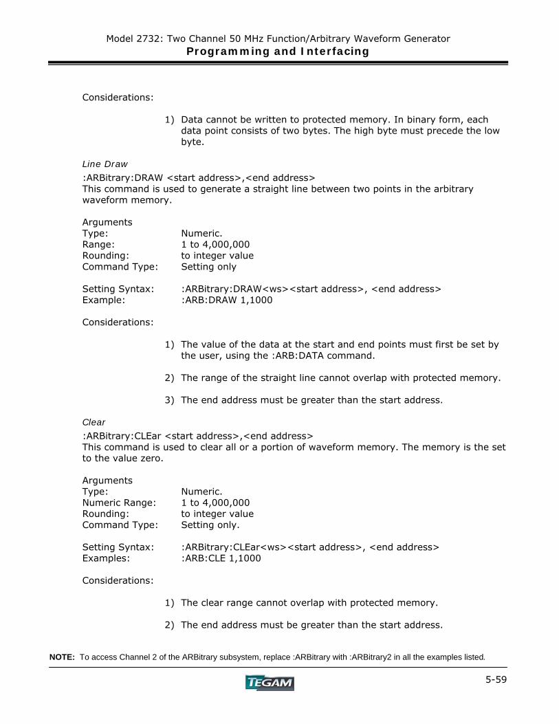
Model 2732: Two Channel 50 MHz Function/Arbitrary Waveform Generator Programming and Interfacing
5-59
Considerations:
1) Data cannot be written to protected memory. In binary form, each
data point consists of two bytes. The high byte must precede the low byte.
Line Draw
:ARBitrary:DRAW <start address>,<end address> This command is used to generate a straight line between two points in the arbitrary waveform memory. Arguments Type: Numeric. Range: 1 to 4,000,000 Rounding: to integer value Command Type: Setting only Setting Syntax: :ARBitrary:DRAW<ws><start address>, <end address> Example: :ARB:DRAW 1,1000 Considerations:
1) The value of the data at the start and end points must first be set by the user, using the :ARB:DATA command.
2) The range of the straight line cannot overlap with protected memory.
3) The end address must be greater than the start address.
Clear
:ARBitrary:CLEar <start address>,<end address> This command is used to clear all or a portion of waveform memory. The memory is the set to the value zero. Arguments Type: Numeric. Numeric Range: 1 to 4,000,000 Rounding: to integer value Command Type: Setting only. Setting Syntax: :ARBitrary:CLEar<ws><start address>, <end address> Examples: :ARB:CLE 1,1000 Considerations:
1) The clear range cannot overlap with protected memory. 2) The end address must be greater than the start address.
NOTE: To access Channel 2 of the ARBitrary subsystem, replace :ARBitrary with :ARBitrary2 in all the examples listed.
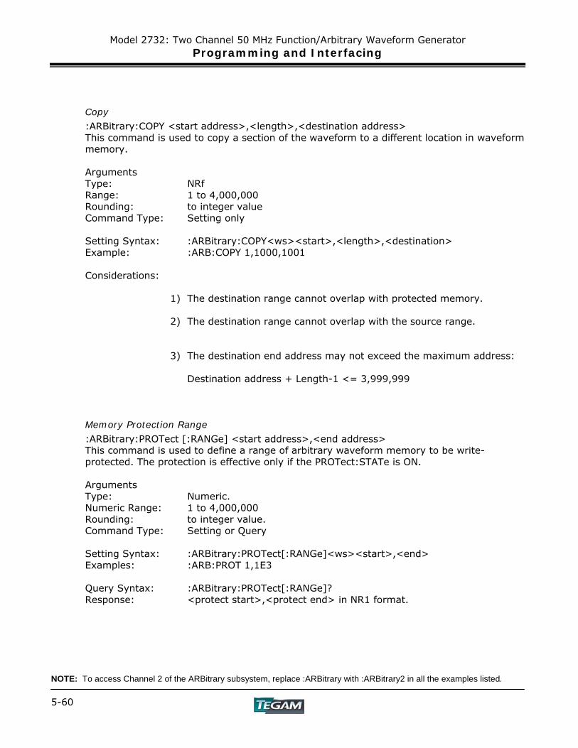
Model 2732: Two Channel 50 MHz Function/Arbitrary Waveform Generator Programming and Interfacing
5-60
Copy
:ARBitrary:COPY <start address>,<length>,<destination address> This command is used to copy a section of the waveform to a different location in waveform memory. Arguments Type: NRf Range: 1 to 4,000,000 Rounding: to integer value Command Type: Setting only Setting Syntax: :ARBitrary:COPY<ws><start>,<length>,<destination> Example: :ARB:COPY 1,1000,1001 Considerations:
1) The destination range cannot overlap with protected memory. 2) The destination range cannot overlap with the source range.
3) The destination end address may not exceed the maximum address:
Destination address + Length-1 <= 3,999,999
Memory Protection Range
:ARBitrary:PROTect [:RANGe] <start address>,<end address> This command is used to define a range of arbitrary waveform memory to be write- protected. The protection is effective only if the PROTect:STATe is ON. Arguments Type: Numeric. Numeric Range: 1 to 4,000,000 Rounding: to integer value. Command Type: Setting or Query Setting Syntax: :ARBitrary:PROTect[:RANGe]<ws><start>,<end> Examples: :ARB:PROT 1,1E3 Query Syntax: :ARBitrary:PROTect[:RANGe]? Response: <protect start>,<protect end> in NR1 format.
NOTE: To access Channel 2 of the ARBitrary subsystem, replace :ARBitrary with :ARBitrary2 in all the examples listed.
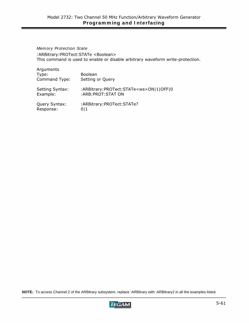
Model 2732: Two Channel 50 MHz Function/Arbitrary Waveform Generator Programming and Interfacing
5-61
Memory Protection State
:ARBitrary:PROTect:STATe <Boolean> This command is used to enable or disable arbitrary waveform write-protection. Arguments Type: Boolean Command Type: Setting or Query Setting Syntax: :ARBitrary:PROTect:STATe<ws>ON|1|OFF|0 Example: :ARB:PROT:STAT ON Query Syntax: :ARBitrary:PROTect:STATe? Response: 0|1
NOTE: To access Channel 2 of the ARBitrary subsystem, replace :ARBitrary with :ARBitrary2 in all the examples listed.
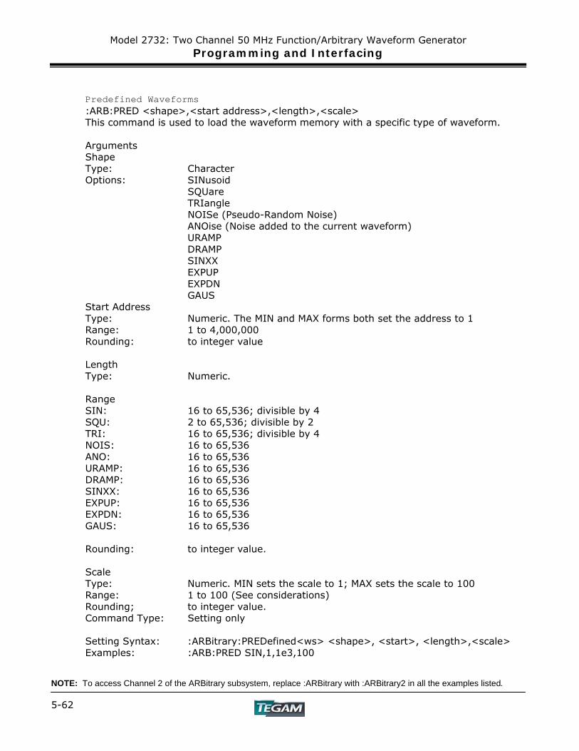
Model 2732: Two Channel 50 MHz Function/Arbitrary Waveform Generator Programming and Interfacing
5-62
Predefined Waveforms
:ARB:PRED <shape>,<start address>,<length>,<scale> This command is used to load the waveform memory with a specific type of waveform. Arguments Shape Type: Character
Options: SINusoid SQUare TRIangle NOISe (Pseudo-Random Noise) ANOise (Noise added to the current waveform) URAMP DRAMP SINXX EXPUP EXPDN GAUS Start Address Type: Numeric. The MIN and MAX forms both set the address to 1 Range: 1 to 4,000,000
Rounding: to integer value Length
Type: Numeric. Range SIN: 16 to 65,536; divisible by 4
SQU: 2 to 65,536; divisible by 2 TRI: 16 to 65,536; divisible by 4 NOIS: 16 to 65,536 ANO: 16 to 65,536
URAMP: 16 to 65,536 DRAMP: 16 to 65,536 SINXX: 16 to 65,536 EXPUP: 16 to 65,536 EXPDN: 16 to 65,536
GAUS: 16 to 65,536 Rounding: to integer value. Scale
Type: Numeric. MIN sets the scale to 1; MAX sets the scale to 100 Range: 1 to 100 (See considerations) Rounding; to integer value.
Command Type: Setting only Setting Syntax: :ARBitrary:PREDefined<ws> <shape>, <start>, <length>,<scale> Examples: :ARB:PRED SIN,1,1e3,100
NOTE: To access Channel 2 of the ARBitrary subsystem, replace :ARBitrary with :ARBitrary2 in all the examples listed.
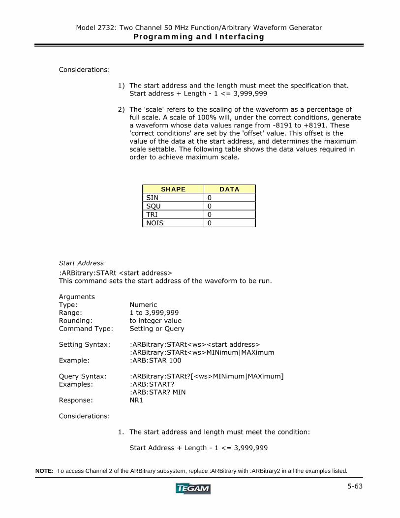
Model 2732: Two Channel 50 MHz Function/Arbitrary Waveform Generator Programming and Interfacing
5-63
Considerations:
1) The start address and the length must meet the specification that. Start address + Length - 1 <= 3,999,999
2) The 'scale' refers to the scaling of the waveform as a percentage of
full scale. A scale of 100% will, under the correct conditions, generate a waveform whose data values range from -8191 to +8191. These 'correct conditions' are set by the 'offset' value. This offset is the value of the data at the start address, and determines the maximum scale settable. The following table shows the data values required in order to achieve maximum scale.
SHAPE DATA SIN 0 SQU 0 TRI 0 NOIS 0
Start Address
:ARBitrary:STARt <start address> This command sets the start address of the waveform to be run. Arguments Type: Numeric Range: 1 to 3,999,999 Rounding: to integer value Command Type: Setting or Query Setting Syntax: :ARBitrary:STARt<ws><start address> :ARBitrary:STARt<ws>MINimum|MAXimum Example: :ARB:STAR 100 Query Syntax: :ARBitrary:STARt?[<ws>MINimum|MAXimum] Examples: :ARB:START? :ARB:STAR? MIN Response: NR1 Considerations:
1. The start address and length must meet the condition: Start Address + Length - 1 <= 3,999,999
NOTE: To access Channel 2 of the ARBitrary subsystem, replace :ARBitrary with :ARBitrary2 in all the examples listed.
Model 2732: Two Channel 50 MHz Function/Arbitrary Waveform Generator Programming and Interfacing
5-64
Wavelength
:ARBitrary:LENGth <length> This command sets the length of the waveform being run. Arguments Type: Numeric Range: 2 to 3,999,999 Rounding: to integer value Command Type: Setting or Query Setting Syntax: :ARBitrary:LENGth<ws><length> :ARBitrary:LENGth<ws>MINimum|MAXimum Example: :ARB:LENG 1E3 Query Syntax: :ARBitrary:LENGth?[<ws>MINimum|MAXimum] Example: :ARB:LENG? Response: NR1 Considerations:
1) Changing the wavelength will change either the frequency.
2) The minimum wavelength is 2.
Marker Address
:ARBitrary:MARKer [:ADDRess] <marker address> This command is used to set the address of the marker. Arguments Type: Numeric. Range: 1 to 3,999,999 Rounding: to integer values Setting Syntax: :ARBitrary:MARKer[:ADDRess]<ws><marker address> Examples: :ARB:MARK 45 Query Syntax: :ARBitrary:MARKer[:ADDRess]? Example: :ARB:MARK? Response: Marker address in NR1 format. Considerations:
1) The marker is only output if it's address is within the range of addresses currently being run.
NOTE: To access Channel 2 of the ARBitrary subsystem, replace :ARBitrary with :ARBitrary2 in all the examples listed.
Model 2732: Two Channel 50 MHz Function/Arbitrary Waveform Generator Programming and Interfacing
5-65
Marker Length
:ARBitrary:MARKer:LENGth <numeric value> This command is used to set the marker length. The marker length is specified by appending a numeric value, to the MARKer keyword. Arguments Type: Numeric Command Type: Setting or Query Setting Syntax: :ARBitrary:MARKer:LENGth<ws><length> Example: :ARB:MARK:LENG 5 Query Syntax: :ARBitrary:MARKer:LENGth? Response: NR1
Marker State
:ARBitrary:MARKer:STATe <Boolean> This command is used to enable or disable the marker. Arguments Type: Boolean Command Type: Setting or Query Setting Syntax: :ARBitrary:MARKer:STATe<ws>ON�1�OFF�0 Query Syntax: :ARBitrary:MARKer:STATe? Response: 0|1
Save
:ARBitrary:SAVe This command is used to save all unsaved arbitrary waveform data into non-volatile memory. Arguments Type: none Command Type: Setting only
Setting Syntax: :ARBitrary: SAVe NOTE: To access Channel 2 of the ARBitrary subsystem, replace :ARBitrary with :ARBitrary2 in all the examples listed.

Model 2732: Two Channel 50 MHz Function/Arbitrary Waveform Generator Programming and Interfacing
5-66
Status Subsystem This subsystem controls the SCPI-defined status reporting structures, which are the QUEStionable and OPERation status registers, and the error/event queue. The OPERation status registers are mandated by SCPI, and so are implemented, but are not used by the hardware. No status is ever reported through them, and they are not detailed in this manual. The following shows STATus structure used:
:STATus :PRESet :QUEue [:NEXT]? :ENABle :QUEStionable :CONDition? :PTRansition <NRf> :NTRansition <NRf> :EVENt? :ENABle <NRf>
Status Preset
:STATus:PRESet This command is used to set certain status values to defined values.
a) The OPERation and QUEstionable enable registers are cleared. b) The Positive transition filters are set to 32767. c) The Negative transition filters are set to 0.
d) Only errors in the range (-440:-100) are enabled to be reported in
the event queue. Command Type: Setting only
Setting Syntax: :STATus:PRESet
Model 2732: Two Channel 50 MHz Function/Arbitrary Waveform Generator Programming and Interfacing
5-67
Error Queue Read
:STATus:QUEue? This query returns the first entry in the error queue, and removes that entry from the queue. Its function is identical to that of the :SYSTem:ERRor? query. Command Type: Query only Query Syntax: :STATus:QUEue[:NEXT]? Response: <Error number>, "<error description>"
Error Queue Enable
:STATus:QUEue:ENABle This command is used to enable individual errors to be placed in the queue when they occur. Those errors not specified in the :ENABle command are disabled from being reported in the error queue. Errors and events enabled to be reported at power on depends on the Power on Status Clear status (set with the *PSC common command). If PSC is set, the status is cleared on power on, and the range of errors enabled is as set by the STATus:PRESet command, ie -440 to -100. If PSC is cleared, the status is not cleared on power on, and the errors and events enabled are those that were enabled before the last power down. Type: Expression The expression data takes the form (NRf|<event range>[{,NRf|<event range>}])
where NRf represents an error number. Entries are rounded to integer values.
An <event range> is defined as NRf:NRf The first number in a range MUST be less than the second.
Up to 6 ranges may be specified using one :ENABle command, representing the 6 ranges of errors/events. The ranges are then separated from each other by Program Data Separators (comma). The entire expression must be enclosed in parentheses(...).
Command Type: Setting or Query Setting Syntax: :STATus:QUEue:ENABle<ws><expression> Example: :STAT:QUE:ENAB (-440:-410,-258:-220,402,-110) Query Syntax: :STATus:QUEue:ENABle? Response: (NRf|<event range>[{,[NRf|event range>]})
Model 2732: Two Channel 50 MHz Function/Arbitrary Waveform Generator Programming and Interfacing
5-68
Questionable Status
The Questionable status data structure is used to alert the user to instrument conditions that affect the signal quality. Two types of conditions are defined. These are:
1) Frequency - Trigger rate conflict. 2) Output overload condition.
Each condition is reported separately for each channel. Thus, a total of four conditions may be reported. The data structure is comprised of five 16-Bit registers. Each bit represents a different status condition. Bits 9 and 11 are used as follows: Bit 9: Frequency - trigger rate conflict. Bit 11: Output overload. The existence of these conditions is indicated in the CONDition register. Bit 3 of the status byte is used to indicate the occurrence of a questionable status condition. The conditions cause this bit to be set depending on the values of the other four registers. The positive transition filter enables a bit in the event register to be set when a condition changes from false to true. The negative transition register enables a bit in the event register to be set when a condition changes from true to false. In order for the bit in the event register to be set, the corresponding bit in the transition register must be set. Bit 3 in the status byte will be set if a bit in the event register is set while the corresponding bit in the enable register is set.
Questionable Condition
:STATus:QUEstionable:CONDition? This query is used to read the condition register. Command Type: Query only Query Syntax: :STATus:QUES:COND? Response: NR1
Model 2732: Two Channel 50 MHz Function/Arbitrary Waveform Generator Programming and Interfacing
5-69
Positive Transition Filter
:STAT:QUES:PTR This command is used to set and query the value of the positive transition filter. Arguments Type: NRf Range: 0 to 131,072. Non-integer arguments are rounded before execution. Command Type: Setting or Query Setting Syntax: :STAT:QUES:PTR<ws><NRf> Examples: :STAT:QUES:PTR 2048 Query Syntax: :STAT:QUES:PTR? Response: NR1
Negative Transition Filter
:STAT:QUES:NTR This command is used to set and query the value of the negative transition filter. Arguments Type: NRf Range: 0 to 131,072. Non-integer arguments are rounded before execution Command Type: Setting or Query Setting Syntax: :STAT:QUES:NTR<ws><NRf> Examples: :STAT:QUES:NTR 2048 Query Syntax: :STAT:QUES:NTR? Response: NR1
Model 2732: Two Channel 50 MHz Function/Arbitrary Waveform Generator Programming and Interfacing
5-70
Event Register
:STAT:QUES:EVENt? This query is used to read the event register. Reading the register clears it. Command Type: Query only Query Syntax: :STATus:QUES:EVEN? Response: NR1
Event Enable Register
:STAT:QUES:ENABle This command is used to set and query the value of the enable register. Arguments Type: NRf Range: 0 to 131,072. Non integer arguments are rounded before execution. Command Type: Setting or Query Setting Syntax: :STAT:QUES:ENAB<ws><NRf> Examples: :STAT:QUES:ENAB 2048 Query Syntax: :STAT:QUES:ENAB? Response: NR1
Model 2732: Two Channel 50 MHz Function/Arbitrary Waveform Generator Programming and Interfacing
5-71
System Subsystem The SYSTem subsystem collects the functions that are not related to instrument performance. The functions implemented in the AWG are security, GPIB address changing, error queue reading, SCPI version reading, and power-on buffer setting (not SCPI-defined). The command structure is as follows:
:SYSTem :COMMunicate :GPIB :ADDRess <numeric value> :ERRor? :VERSion? :SECurity [:STATe] <Boolean> :POBuffer <numeric value> GPIB Address Change :SYSTem:COMMunicate:GPIB:ADDRess This command is used to set the GPIB address. Arguments Type: Numeric Range: 0 to 31 Rounding: to integer value Command Type: Setting or Query
Setting Syntax: :SYSTem:COMMunicate:GPIB:ADDRess<ws><address>|MINimum|MAXimum Example: :SYST:COMM:GPIB:ADDR 20
Query Syntax: :SYSTem:COMMunicate:GPIB:ADDRess?[<ws>MINimum|MAXimum] Response: <address> in NR1 format Considerations:
1) Setting the address to 31 puts the instrument in the off-bus state. 2) Using the MAX option sets the address to 30, not 31.
Default Power-on is address 9.
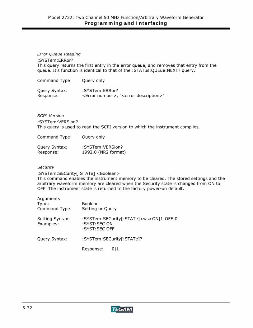
Model 2732: Two Channel 50 MHz Function/Arbitrary Waveform Generator Programming and Interfacing
5-72
Error Queue Reading
:SYSTem:ERRor? This query returns the first entry in the error queue, and removes that entry from the queue. It's function is identical to that of the :STATus:QUEue:NEXT? query. Command Type: Query only Query Syntax: :SYSTem:ERRor? Response: <Error number>, "<error description>"
SCPI Version
:SYSTem:VERSion? This query is used to read the SCPI version to which the instrument complies. Command Type: Query only Query Syntax; :SYSTem:VERSion? Response: 1992.0 (NR2 format)
Security
:SYSTem:SECurity[:STATe] <Boolean> This command enables the instrument memory to be cleared. The stored settings and the arbitrary waveform memory are cleared when the Security state is changed from ON to OFF. The instrument state is returned to the factory power-on default. Arguments Type: Boolean Command Type: Setting or Query Setting Syntax: :SYSTem:SECurity[:STATe]<ws>ON|1|OFF|0 Examples: :SYST:SEC ON :SYST:SEC OFF Query Syntax: :SYSTem:SECurity[:STATe]?
Response: 0|1
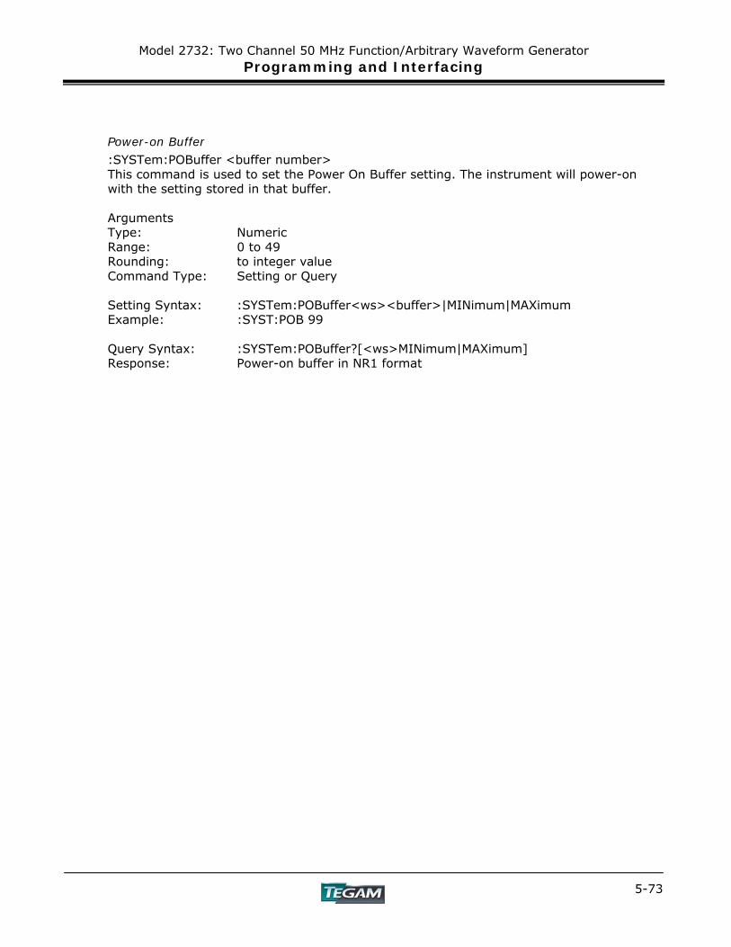
Model 2732: Two Channel 50 MHz Function/Arbitrary Waveform Generator Programming and Interfacing
5-73
Power-on Buffer
:SYSTem:POBuffer <buffer number> This command is used to set the Power On Buffer setting. The instrument will power-on with the setting stored in that buffer. Arguments Type: Numeric Range: 0 to 49 Rounding: to integer value Command Type: Setting or Query Setting Syntax: :SYSTem:POBuffer<ws><buffer>|MINimum|MAXimum Example: :SYST:POB 99 Query Syntax: :SYSTem:POBuffer?[<ws>MINimum|MAXimum] Response: Power-on buffer in NR1 format
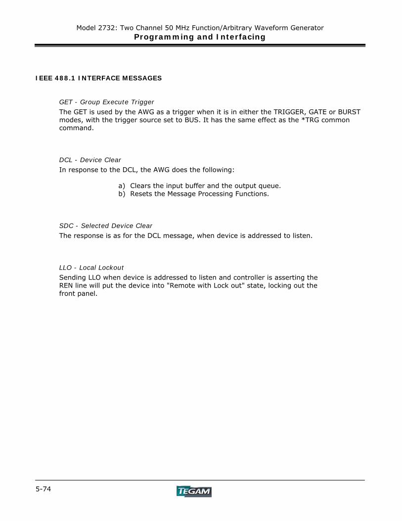
Model 2732: Two Channel 50 MHz Function/Arbitrary Waveform Generator Programming and Interfacing
5-74
IEEE 488.1 INTERFACE MESSAGES
GET - Group Execute Trigger
The GET is used by the AWG as a trigger when it is in either the TRIGGER, GATE or BURST modes, with the trigger source set to BUS. It has the same effect as the *TRG common command.
DCL - Device Clear
In response to the DCL, the AWG does the following:
a) Clears the input buffer and the output queue. b) Resets the Message Processing Functions.
SDC - Selected Device Clear
The response is as for the DCL message, when device is addressed to listen.
LLO - Local Lockout
Sending LLO when device is addressed to listen and controller is asserting the REN line will put the device into "Remote with Lock out" state, locking out the front panel.
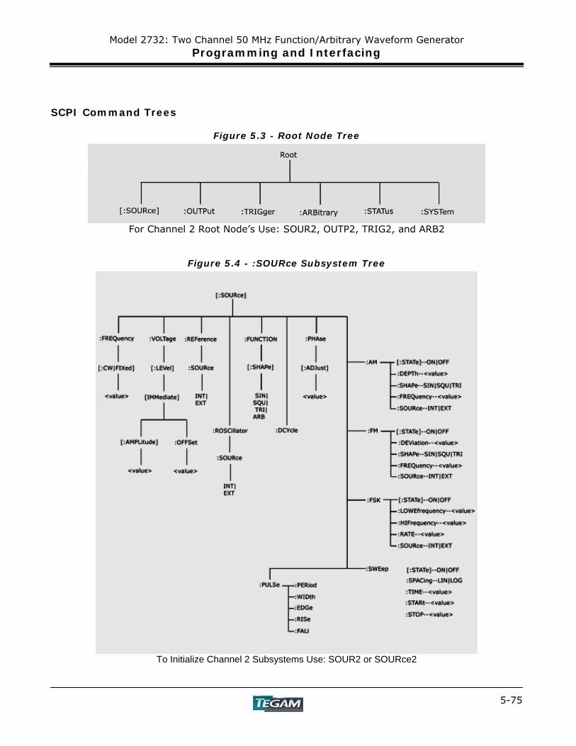
Model 2732: Two Channel 50 MHz Function/Arbitrary Waveform Generator Programming and Interfacing
5-75
SCPI Command Trees
Figure 5.3 - Root Node Tree
For Channel 2 Root Node’s Use: SOUR2, OUTP2, TRIG2, and ARB2
Figure 5.4 - :SOURce Subsystem Tree
To Initialize Channel 2 Subsystems Use: SOUR2 or SOURce2
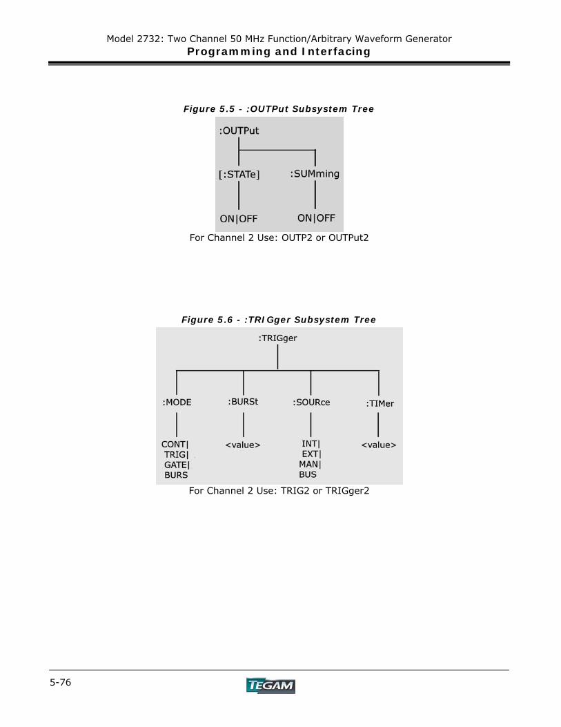
Model 2732: Two Channel 50 MHz Function/Arbitrary Waveform Generator Programming and Interfacing
5-76
Figure 5.5 - :OUTPut Subsystem Tree
For Channel 2 Use: OUTP2 or OUTPut2
Figure 5.6 - :TRIGger Subsystem Tree
For Channel 2 Use: TRIG2 or TRIGger2
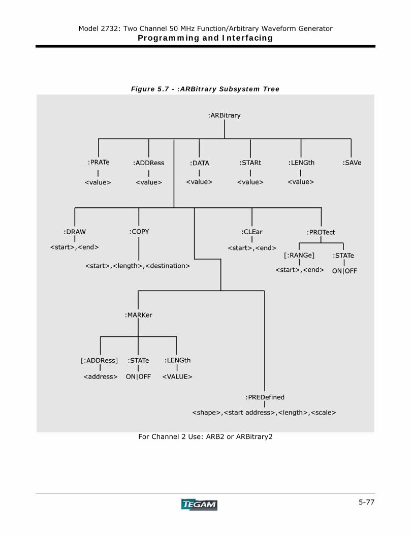
Model 2732: Two Channel 50 MHz Function/Arbitrary Waveform Generator Programming and Interfacing
5-77
Figure 5.7 - :ARBitrary Subsystem Tree
For Channel 2 Use: ARB2 or ARBitrary2
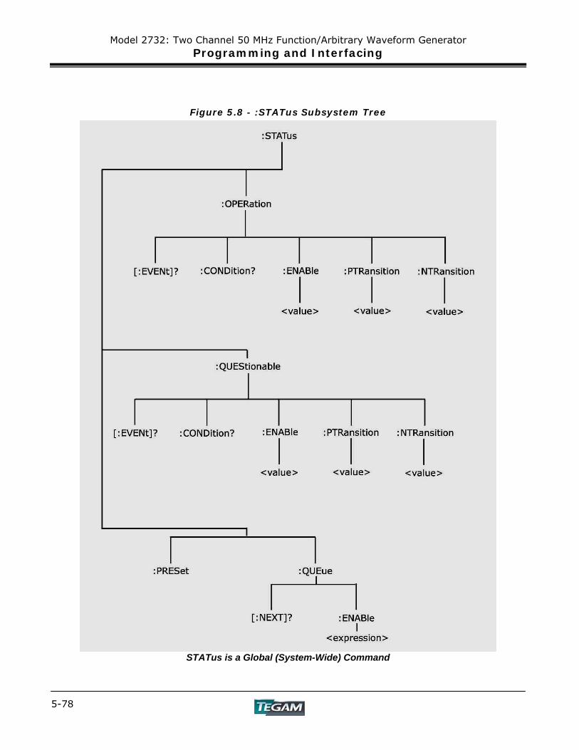
Model 2732: Two Channel 50 MHz Function/Arbitrary Waveform Generator Programming and Interfacing
5-78
Figure 5.8 - :STATus Subsystem Tree
STATus is a Global (System-Wide) Command
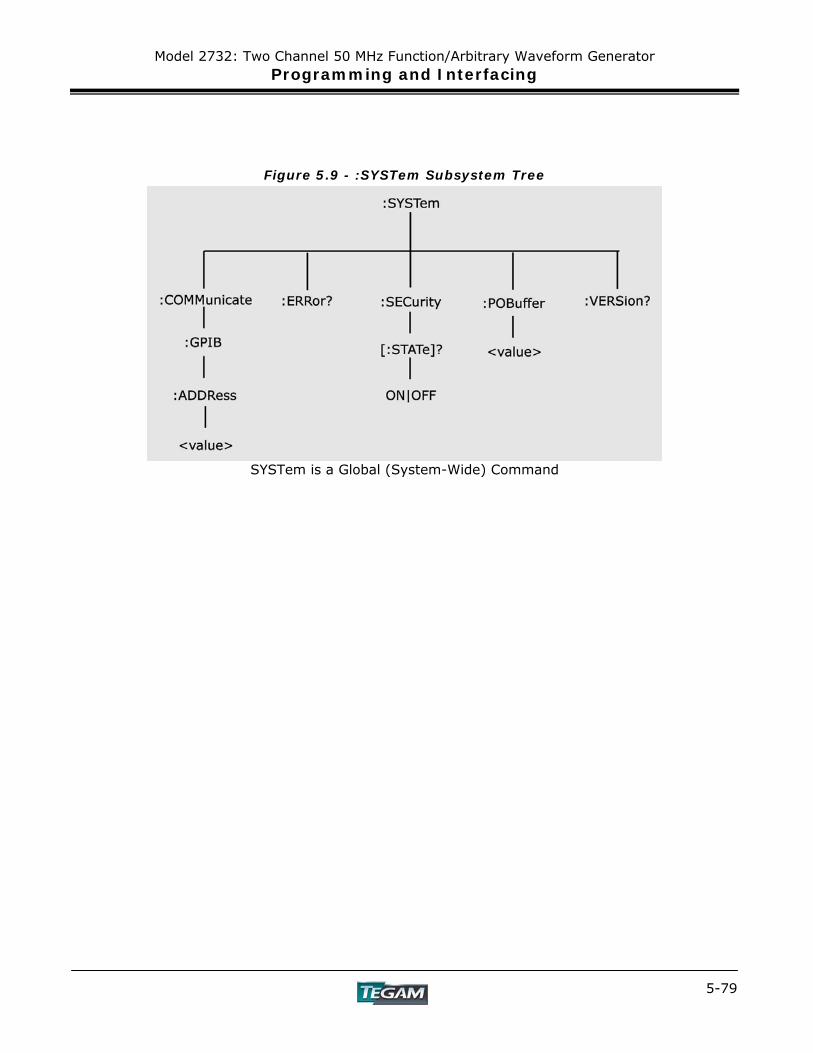
Model 2732: Two Channel 50 MHz Function/Arbitrary Waveform Generator Programming and Interfacing
5-79
Figure 5.9 - :SYSTem Subsystem Tree
SYSTem is a Global (System-Wide) Command
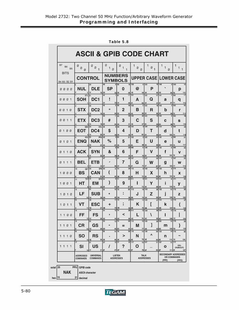
Model 2732: Two Channel 50 MHz Function/Arbitrary Waveform Generator Programming and Interfacing
5-80
Table 5.8
Model 2732: Two Channel 50 MHz Function/Arbitrary Waveform Generator Programming and Interfacing
5-81
Block Transfer
Arbitrary waveform data sent in IEEE488.2 arbitrary block format may take two forms: the definite form and the indefinite form. The essential difference between these forms is that the definite form contains a byte count, while the indefinite form does not. In both cases, the format of the command is
:ARB:DATA<ws><preamble><data><terminator>.
The <data> represents the arbitrary waveform data. This field consists of 8 bit bytes sent in hexadecimal form. Each arbitrary data point consists of two bytes with the high byte being sent first. When sending data in this way, the value of a data point may range from -8191 (corresponding to the negative peak), to 8191 (corresponding to the positive peak). The value 0 corresponds to zero baseline. Compare the ASCII, or front panel representation, which defines data in the range – 8191 to + 8191.
Example: to set a data value to zero, send the Hex bytes 0800
The definite form <preamb4> consists of two fields. The first is a single byte representing the number of digits in the byte count. The byte count is the second field in the preamble, and consists of decimal bytes (0-9), which, when taken together, give the byte count. For example, the preamble 42563
means that the byte count consists of 4 bytes, and that the byte count is 2563 bytes. The indefinite form preamble consists of a 0 character alone. Both the definite and indefinite forms have a '#' prefix in the preamble.
Another difference is that the indefinite form, since it does not contain a byte count, must be terminated with LF^EOI. Since each arbitrary data point consists of two bytes, an even number of bytes must be sent. In the following examples, the data is specified in Hex format with each byte being preceded by ' \x', in order to show this.
Example of definite form:
:ARB:DATA #16\x8\x0\x8\x1\x8\x2
Here, the byte count consists of one byte only, and the value is 6. Example to definite form:
:ARB:DATA #0\x8\x0\x8\x1\x8\x2\x0A

Model 2732: Two Channel 50 MHz Function/Arbitrary Waveform Generator Programming and Interfacing
5-82
The '\x0A' represents the Linefeed character. EOI must be sent with this character. Arbitrary data read from the instrument in binary form, as opposed to ASCII, are returned in indefinite form. Before sending your data enable all errors to be reported, using
:STAT:QUEUE:ENABLE ALL.
Then, if the arb data command causes an error, the error message may be read from the queue using the query.
:SYST:ERR?
Model 2732: Two Channel 50 MHz Function/Arbitrary Waveform Generator Programming and Interfacing
5-83
GPIB Communication Protocol
General
This appendix describes the effects of interface messages on waveform generator operation and uses abbreviations from the IEEE Standard 488.1-1987.
Responses to IEEE-488.1 Interface Messages
Interface messages and the effects of those messages on the instrument interface functions are defined in IEEE Standard 488.1-1987. Where appropriate, the GPIB code is listed, in decimal.
UNL-Unlisten (63 with ATN) UNT-Untalk (95 with ATN)
The UNL command places the listener function to its idle (unaddressed) state. In this idle state, the waveform generator cannot accept commands from the GPIB.
The UNT command places the talker function to its idle state. In this idle state, the waveform generator cannot output data through the GPIB.
When the talker and listener functions are idle, the front-panel ADRS indicator is off. If the waveform generator is talk-addressed or listen-addressed, the ADRS indicator lights.
IFC-Interface Clear (Bus pin 9)
The IFC message places both the listener and talk functions to idle states. When the talker and listener functions are idle, the front-panel ADRS indicator is off.
The IFC pulse is >= 100us. DCL-Device Clear (20 with ATN)
The Device Clear message resets GPIB communication. That is, the DCL message clears all input and output messages, as well as all unexecuted settings.
SDC-Selected Device Clear (4 with ATN)
The SDC message causes the same response as the DCL message. However, the waveform generator only responds if it is listen-addressed.
Model 2732: Two Channel 50 MHz Function/Arbitrary Waveform Generator Programming and Interfacing
5-84
GET-Group Execute Trigger (8 with ATN)
The waveform generator responds to the Group Execute Trigger message only if it is listen addressed and the device trigger function is enabled. The TRIGger:MODE must be in TRIG, CONTinuous, or BURst and the TRIGger:SOURce must be set to BUS to enable device triggering via GET.
SPE-Serial Poll Enable (24 with ATN) The SPE message generates output serial poll status bytes when talk-addressed. SPD-Serial Poll Disable (25 with ATN) The SPD message switches back to generating output data from the Output Buffer. MLA-My Listen Address (GPIB Address + 32) MTA-My Talk Address (GPIB Address + 64)
The instrument GPIB primary address establishes the listen and talk addresses. To see the current GPIB primary address, press SPECIAL and then F1:SYS on the front panel. When the waveform generator is talk-addressed or listen-addressed, the front-panel ADRS indicator lights.
LLO-Local Lockout (17 with ATN)
When the waveform generator is listen addressed, the LLO message changes the waveform generator to the front-panel lockout state.
REN-Remote Enable (GPIB pin 17)
REN is normally held true by the controller and allows the controller to then put the waveform generator into one of the remote states. Pulsing REN false or holding it false forces the device into local state (LOCS).
NOTE:
If you disconnect and reconnect the GPIB cable when the controller is holding REN true, the REN goes false and the device got to local state (LOCS).
Model 2732: Two Channel 50 MHz Function/Arbitrary Waveform Generator Programming and Interfacing
5-85
GTL-Go To Local (1 with ATN)
Listen-addressed instruments respond to GTL by changing to a local state. Remote-to-local transitions caused by GTL do not affect the execution of the message being processed when GTL was received.
Remote-Local Operation
Most front-panel controls cause a transition from REMS to LOCS by asserting a message called return-to-local (rtl). This transition can occur during message execution. However, in contrast to TGL and REN transitions, a transition initiated by rtl affects message execution. In this case, the waveform generator generates an error if there are any unexecuted setting or operational commands.
Front-panel controls that change only the display, do not affect the remote-local states. Only front-panel controls that change settings assert rtl. The rtl message remains asserted when you enter multiple keystroke settings from the front panel, and is unasserted after you execute the settings changes. Since rtl prevents transition to REMS, the waveform generator unasserts rtl if you do not complete a multiple key sequence in a reasonable length of time (about 5 to 10 seconds).
A record of the front-panel settings is in the Current Settings Buffer; however, new settings entered from the front panel or the controller update these recorded settings. In addition, the front panel updates to reflect setting changes from controller commands. Settings are unaffected by transitions among the 4 remote-local states. The REMOTE indicator lights when the waveform generator is in REMS or RWLS.
Local State (LOCS)
When in a local state (LOCS), you control the settings through the front-panel controls. In addition, only GPIB query commands are executed. All other GPIB commands, settings and operations prompt an error since those commands are under front-panel (local) control.
NOTE: The waveform generator can be in either Local State (LOCS) or Remote State (REMS) when it receives the Local Lockout (LLO) interface message. If in LOCS and REN is asserted, the waveform generator enters the Local With Lockout State (LWLS) or, if in REMS, it enters the Remote With Lockout State (RWLS) when it receives LLO. The controller controls the LWLS and RWLS state transitions.
Model 2732: Two Channel 50 MHz Function/Arbitrary Waveform Generator Programming and Interfacing
5-86
Local Without Lockout State (LWLS)
When the waveform generator is in a local without lockout state (LWLS), it operates the same as it does in LOCS. However, in LWLS rtl does not inhibit a transition to remote state.
Remote State (REMS)
When the waveform generator is in a remote state (REMS), you control its operations from the controller. All settings update when GPIB are executed.
Remote With Lockout State (RWLS)
When in a remote with lockout state (RWLS), the waveform generator operates much the same as it does in LOCS. However, when in RWLS the waveform generator ignores the rtl message, locking out any changes made from the front panel.
IEEE 488.2 Interface Function Subsets
IEEE Standard 488.2 identifies the interface function repertoire of a device on the bus in terms of interface function subsets. These subsets are defined in the standard. Table C-1 lists the subsets that apply to the waveform generator.
NOTE: For more information, refer to IEEE Standard 488.2. The standard is published by the Institute of Electrical and Electronics Engineers, Inc., 345 East 47 Street, New York, New York 10017.
Model 2732: Two Channel 50 MHz Function/Arbitrary Waveform Generator Programming and Interfacing
5-87
Table 5.9: Interface Function Subsets
FUNCTION SUBSET CAPABILITY
Source Handshake SH1 Complete capability
Acceptor Handshake AH1 Complete capability
Basic Talker T6 Responds to Serial Poll, Untalk if My Listen Address (MLA) is received
Basic Listener L4 Unlisten if My Talk Address (MTA) is received
Service Request SR1 Complete capability
Remote-Local RL1 Complete capability, including Local Lockout (LLO)
Parallel Poll PP0 Does not respond to Parallel Poll
Device Clear DC1 Complete capability
Device Trigger DT1 Complete capability
Controller C0 No controller functions
Electrical Interface E2 Three-state drive capability

Model 2732: Two Channel 50 MHz Function/Arbitrary Waveform Generator 6-1
Service Information
INSTRUMENT DESCRIPTION PREPARATION FOR USE
QUICK START INSTRUCTIONS OPERATING INSTRUCTIONS
PROGRAMMING & INTERFACING SERVICE INFORMATION
APPENDIX

Model 2732: Two Channel 50 MHz Function/Arbitrary Waveform Generator Service Information
6-2
Model 2732: Two Channel 50 MHz Function/Arbitrary Waveform Generator Service Information
6-3
Warranty: TEGAM, Inc. warrants this product to be free from defects in material and workmanship for a period of three years from the date of shipment. During this warranty period, if a product proves to be defective, TEGAM Inc., at its option, will either repair the defective product without charge for parts and labor, or exchange any product that proves to be defective. TEGAM, Inc. warrants the calibration of this product for a period of 12 months from date of shipment. During this period, TEGAM, Inc. will recalibrate any product, which does not conform to the published accuracy specifications. In order to exercise this warranty, TEGAM, Inc., must be notified of the defective product before the expiration of the warranty period. The customer shall be responsible for packaging and shipping the product to the designated TEGAM service center with shipping charges prepaid. TEGAM Inc. shall pay for the return of the product to the customer if the shipment is to a location within the country in which the TEGAM service center is located. The customer shall be responsible for paying all shipping, duties, taxes, and additional costs if the product is transported to any other locations. Repaired products are warranted for the remaining balance of the original warranty, or 90 days, whichever period is longer. Warranty Limitations: The TEGAM, Inc. warranty does not apply to defects resulting from unauthorized modification or misuse of the product or any part. This warranty does not apply to fuses, batteries, or damage to the instrument caused by battery leakage. Statement of Calibration: This instrument has been inspected and tested in accordance with specifications published by TEGAM Inc. The accuracy and calibration of this instrument are traceable to the National Institute of Standards and Technology through equipment, which is calibrated at planned intervals by comparison to certified standards maintained in the laboratories of TEGAM Inc. Contact Information: TEGAM INC. 10 TEGAM WAY GENEVA, OHIO 44041 PH: 440.466.6100 FX: 440.466.6110
EMAIL: [email protected]

Model 2732: Two Channel 50 MHz Function/Arbitrary Waveform Generator Service Information
6-4
Repair Parts The Model 2732 has no user replaceable parts. Available accessories are listed in Section I.

Model 2732: Two Channel 50 MHz Function/Arbitrary Waveform Generator Service Information
6-5
Troubleshooting: The TEGAM Model 2732 has been designed to provide many years of trouble free performance. However, there are some instances where harsh operating environments or excessive physical strain may cause premature failure. Should a malfunction of the 2732 be observed, it is recommended that certain steps be taken in order to assist our service department in identifying the cause of the malfunction and to provide the quickest possible turn around time for the repair cycle. Below is a summary of some commonly observed symptoms and some possible remedies for ruling out the possibilities of user error or environmentally-related problems. No Display – The display is completely blank.
• Check the power supply. Make sure that the AC line is operational and is supplying power to the unit.
• Check the fuse located in the rear panel. If a blown fuse is identified there is usually a reason for the fuse blowing, so the probability of another related problem is high.

Model 2732: Two Channel 50 MHz Function/Arbitrary Waveform Generator Service Information
6-6
Preparation for Repair or Calibration Service: Once you have verified that the cause for the 2732 problem cannot be solved in the field and the need for repair and calibration service arises, contact TEGAM customer service to obtain an RMA, (Returned Material Authorization), number. You can contact TEGAM customer service via the TEGAM website, www.tegam.com or by calling 440.466.6100 OR 800.666.1010. The RMA number is unique to your instrument and will help us identify your instrument and to address the particular service request by you which is assigned to that RMA number. Of even greater importance, a detailed written description of the problem should be attached to the instrument. Many times repair turnaround is unnecessarily delayed due to a lack of repair instructions or of a detailed description of the problem. This description should include information such as measurement settings, type of components being tested, whether the problem is intermittent or constant, when is the problem most frequent, has the test changed since the last time the instrument was used, etc.. Any detailed information provided to our technicians will assist them in identifying and correcting the problem in the quickest possible manner. Use the Expedite Repair & Calibration form provided on the next page. Once this information is prepared and sent with the instrument and RMA number to our service department, we will do our part in making sure that you receive the best possible turnaround.
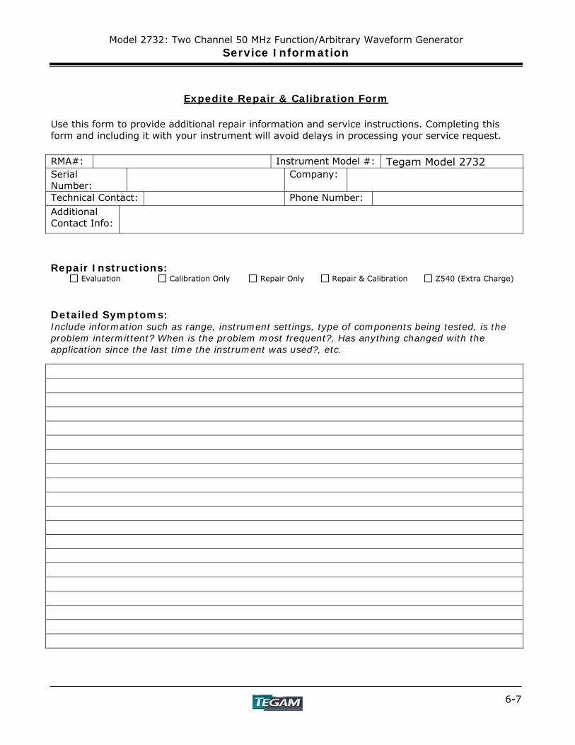
Model 2732: Two Channel 50 MHz Function/Arbitrary Waveform Generator Service Information
6-7
Expedite Repair & Calibration Form Use this form to provide additional repair information and service instructions. Completing this form and including it with your instrument will avoid delays in processing your service request. RMA#: Instrument Model #: Tegam Model 2732 Serial Number:
Company:
Technical Contact: Phone Number: Additional Contact Info:
Repair Instructions: Evaluation Calibration Only Repair Only Repair & Calibration Z540 (Extra Charge) Detailed Symptoms: Include information such as range, instrument settings, type of components being tested, is the problem intermittent? When is the problem most frequent?, Has anything changed with the application since the last time the instrument was used?, etc.
Model 2732: Two Channel 50 MHz Function/Arbitrary Waveform Generator Service Information
6-8
Model 2732 Performance Verification:
Introduction This section provides a procedure to verify that the Model 2732 has met the specifications published in the manual to within stated tolerances. There are no user accessible calibration points in the unit. TEGAM, Inc. recommends an annual calibration verification interval. It is recommended that the Operating Section of the instruction manual should be followed in order to verify proper operation of the unit. Copy the Verification Test Sheet at the end of this chapter to record the data. Test Equipment Required Analog Oscilloscope: 200 MHz or greater bandwidth. Frequency Counter: 1 ppm or better accuracy. True RMS Digital Multimeter: 5-1/2 digit, 0.1% or better accuracy. Distortion Analyzer: 0.01% or better THD measurement at 80 kHz bandwidth. Precision Load: 50Ω, +/- 0.1% Environmental Conditions These tests are to be performed at a temperature of 25°C, ±5°C (77°F, ±9°F) with a relative humidity of less than 80%. Allow the instrument to warm up for at least one hour before performing these tests. Verification Test Frequency Accuracy 1. Connect the frequency counter input to the 10 MHz CLK Output on the rear panel. 2. Verify that the output frequency is 10 MHz, ±20 ppm The following procedures require the instrument to be reset to the default settings. Please save pertinent waveform data contained in the 2732 to a PC or disk before proceeding to the next test Reset the instrument to the factory default settings by depressing [SETUPS], [F1], [0], [ENTER]. Waveform Rise/Fall Time Use the shortest possible BNC cables when performing Rise/Fall time verification 1. Set Amplitude to 10 Vp-p. 2. Depress the [WAVE] switch. Depress [F2] to select the Square Wave. 3. Connect OUTPUT to the oscilloscope input. Be sure it is terminated with the 50Ω load. 4. Ensure that the OUTPUT [ON] indicator is active on the upper right hand corner of the LCD. If
not, depress the [ON] switch above the OUTPUT connector. 5. Verify the rise and fall times of the square wave to be less than 6 ns (10% to 90%). 6. Repeat this process for Channel 2.
Model 2732: Two Channel 50 MHz Function/Arbitrary Waveform Generator Service Information
6-9
Model 2732 Performance Verification cont’d: DC Offset Accuracy 1. Select a SINE wave with a frequency of 1 kHz and 1.00 Vp-p amplitude. 2. Connect Channel 1 OUTPUT to the DMM input with the 50Ω load. 3. Set OFST to 4.50 V. 4. Set the DMM to DC measurement and verify the DC Offset measures between 4.445 V and
4.555 V. 5. Set OFST to 900 mV. 6. Verify that DC Offset measures between 0.881 V and 0.919 V. 7. Set OFST to 90 mV. 8. Verify that DC Offset from Channel 1 measures between 0.0791 V and 0.1009 V 9. Repeat this process for Channel 2. Amplitude Accuracy 1. Select a SINE wave with a frequency of 1 kHz and 0.00 V offset. 2. Connect OUTPUT to the DMM with the 50 Ω load. 3. Set the Amplitude to 10.00 Vpeak. 4. Measure the true RMS amplitude on the DMM. 5. Verify the true RMS amplitude is between 6.99 VRMS and 7.15 VRMS. 6. Set the Amplitude to 1.00 Vpeak. 7. Measure the true RMS amplitude on DMM. 8. Verify the true RMS amplitude is between 0.686 VRMS and 0.728 VRMS. 9. Repeat the process for Channel 2. Total Harmonic Distortion (THD) plus Noise 1. Use Channel 1 to select a SINE wave with 0.00 V offset. 2. Set the Amplitude to 9.10 V. 3. Set the Frequency to 20.00 kHz. 4. Connect Channel 1 OUTPUT to the distortion analyzer input using a 50Ω load. 5. Set the distortion analyzer for a 20 kHz signal and 80 kHz measurement bandwidth. 6. Verify THD + Noise measures less than –65 dBc. 7. Repeat the process for Channel 2.
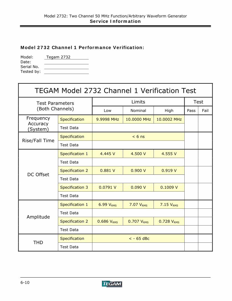
Model 2732: Two Channel 50 MHz Function/Arbitrary Waveform Generator Service Information
6-10
Model 2732 Channel 1 Performance Verification: Model: Tegam 2732 Date: Serial No. Tested by:
TEGAM Model 2732 Channel 1 Verification Test
Limits Test Test Parameters (Both Channels) Low Nominal High Pass Fail
Specification 9.9998 MHz 10.0000 MHz 10.0002 MHz Frequency Accuracy (System) Test Data
Specification < 6 ns Rise/Fall Time
Test Data
Specification 1 4.445 V 4.500 V 4.555 V
Test Data
Specification 2 0.881 V 0.900 V 0.919 V
Test Data
Specification 3 0.0791 V 0.090 V 0.1009 V
DC Offset
Test Data
Specification 1 6.99 VRMS 7.07 VRMS 7.15 VRMS
Test Data
Specification 2 0.686 VRMS 0.707 VRMS 0.728 VRMS Amplitude
Test Data
Specification < - 65 dBc THD
Test Data
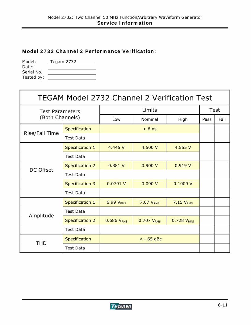
Model 2732: Two Channel 50 MHz Function/Arbitrary Waveform Generator Service Information
6-11
Model 2732 Channel 2 Performance Verification: Model: Tegam 2732 Date: Serial No. Tested by:
TEGAM Model 2732 Channel 2 Verification Test
Limits Test Test Parameters (Both Channels) Low Nominal High Pass Fail
Specification < 6 ns Rise/Fall Time
Test Data
Specification 1 4.445 V 4.500 V 4.555 V
Test Data
Specification 2 0.881 V 0.900 V 0.919 V
Test Data
Specification 3 0.0791 V 0.090 V 0.1009 V
DC Offset
Test Data
Specification 1 6.99 VRMS 7.07 VRMS 7.15 VRMS
Test Data
Specification 2 0.686 VRMS 0.707 VRMS 0.728 VRMS Amplitude
Test Data
Specification < - 65 dBc THD
Test Data
Appendix
SPECIFICATIONS PREPARATION FOR USE
QUICK START INSTRUCTIONS OPERATING INSTRUCTIONS
PROGRAMMING & INTERFACING SERVICE INFORMATION
APPENDIX


Model 2732: Two Channel 50 MHz Function/Arbitrary Waveform Generator Appendix