


Technology of FLUOROPOLYMERS · 2018-09-09 · Chapter 6 Technology and Applications of Aqueous...
250
Transcript of Technology of FLUOROPOLYMERS · 2018-09-09 · Chapter 6 Technology and Applications of Aqueous...

CRC Press is an imprint of theTaylor & Francis Group, an informa business
Boca Raton London New York
Technology of
FLUOROPOLYMERSJiri George Drobny
Second Edition
CRC PressTaylor & Francis Group6000 Broken Sound Parkway NW, Suite 300Boca Raton, FL 33487-2742
© 2009 by Taylor & Francis Group, LLC CRC Press is an imprint of Taylor & Francis Group, an Informa business
No claim to original U.S. Government worksPrinted in the United States of America on acid-free paper10 9 8 7 6 5 4 3 2 1
International Standard Book Number-13: 978-1-4200-6317-2 (Hardcover)
This book contains information obtained from authentic and highly regarded sources. Reasonable efforts have been made to publish reliable data and information, but the author and publisher can-not assume responsibility for the validity of all materials or the consequences of their use. The authors and publishers have attempted to trace the copyright holders of all material reproduced in this publication and apologize to copyright holders if permission to publish in this form has not been obtained. If any copyright material has not been acknowledged please write and let us know so we may rectify in any future reprint.
Except as permitted under U.S. Copyright Law, no part of this book may be reprinted, reproduced, transmitted, or utilized in any form by any electronic, mechanical, or other means, now known or hereafter invented, including photocopying, microfilming, and recording, or in any information storage or retrieval system, without written permission from the publishers.
For permission to photocopy or use material electronically from this work, please access www.copy-right.com (http://www.copyright.com/) or contact the Copyright Clearance Center, Inc. (CCC), 222 Rosewood Drive, Danvers, MA 01923, 978-750-8400. CCC is a not-for-profit organization that pro-vides licenses and registration for a variety of users. For organizations that have been granted a photocopy license by the CCC, a separate system of payment has been arranged.
Trademark Notice: Product or corporate names may be trademarks or registered trademarks, and are used only for identification and explanation without intent to infringe.
Library of Congress Cataloging-in-Publication Data
Drobny, Jiri George.Technology of fluoropolymers / Jiri G. Drobny. -- 2nd ed.
p. cm.Includes bibliographical references and index.ISBN 978-1-4200-6317-2 (alk. paper)1. Fluoropolymers. I. Title.
TP1180.F6D76 2009668.4’238--dc22 2008032890
Visit the Taylor & Francis Web site athttp://www.taylorandfrancis.com
and the CRC Press Web site athttp://www.crcpress.com

vii
ContentsPreface to the First Edition .................................................................................... xiiiPreface to the Second Edition ..................................................................................xvAcknowledgments ..................................................................................................xviiAbout the Author ....................................................................................................xix
Chapter 1 Introduction ..........................................................................................1
Chapter 2 Basic Chemistry of Fluoropolymers .....................................................7
2.1 Polytetrafluoroethylene ...................................................................................72.1.1 Industrial Synthesis of Tetrafluoroethylene ........................................72.1.2 Properties of Tetrafluoroethylene .......................................................82.1.3 Uses of Tetrafluoroethylene ................................................................92.1.4 Polymerization of Tetrafluoroethylene ...............................................9
2.2 Fluorinated Ethylene Propylene (FEP) ......................................................... 132.2.1 Industrial Synthesis of HFP .............................................................. 132.2.2 Properties of HFP ............................................................................. 132.2.3 Industrial Process for the Production of FEP ................................... 14
2.3 Perfluoroalkoxy (PFA) Resin ........................................................................ 142.3.1 Industrial Synthesis of Perfluoroalkyl Vinyl Ether Monomers ........ 142.3.2 Properties of Perfluoroalkylvinyl Ethers .......................................... 152.3.3 Industrial Process for the Production of Perfluoroalkoxy Resins ..... 15
2.4 Polychlorotrifluoroethylene (PCTFE) ........................................................... 152.4.1 Industrial Synthesis of Chlorotrifluoroethylene Monomer ............... 152.4.2 Properties of CTFE ........................................................................... 152.4.3 Industrial Process for the Production of PCTFE .............................. 16
2.5 Polyvinylidene Fluoride (PVDF) .................................................................. 162.5.1 Industrial Synthesis of Vinylidene Fluoride Monomer .................... 162.5.2 Properties of Vinylidene Fluoride .................................................... 172.5.3 Industrial Process for the Production of PVDF ................................ 17
2.6 Polyvinyl Fluoride (PVF) .............................................................................. 182.6.1 Industrial Synthesis of Vinyl Fluoride (VF) Monomer .................... 182.6.2 Industrial Process for the Production of PVF ................................... 18
2.7 Ethylene Chlorotrifluoroethylene (ECTFE) Copolymer ............................... 182.7.1 Industrial Process for the Production of ECTFE .............................. 18
2.8 Ethylene Tetrafluoroethylene (ETFE) Copolymer ........................................ 192.8.1 Industrial Process for the Production of ETFE ................................ 19
2.9 Terpolymers of TFE, HFP, and VDF (THV Fluoroplastic) .......................... 192.10 Terpolymers of HFP, TFE, and Ethylene (Hexafluoropropylene, Tetrafluoroethylene, and Ethylene Fluoroplastic) ..........................................20
viii Technology of Fluoropolymers, Second Edition
2.11 Fluorocarbon Elastomers ..............................................................................202.11.1 Industrial Process for the Production of Fluorocarbon Elastomers ..................................................................................................... 21
2.12 Fluorosilicones .............................................................................................. 212.12.1 Industrial Process for the Production of Fluorosilicones ................22
2.13 Phosphazenes ................................................................................................22
Chapter 3 Properties of Commercial Fluoropolymers ........................................29
3.1 Properties as Related to the Structure of the Polymers ................................293.1.1 Fluoroplastics ....................................................................................293.1.2 Fluoroelastomers ............................................................................... 33
3.2 Properties of Individual Commercial Fluoropolymers .................................343.2.1 Polytetrafluoroethylene .....................................................................343.2.2 Copolymers of Tetrafluoroethylene and Hexafluoropropylene (FEP) .............................................................. 383.2.3 Copolymers of Tetrafluoroethylene and Perfluoroalkyl Ethers (PFA and MFA) ................................................................................ 413.2.4 Copolymers of Ethylene and Tetrafluoroethylene (ETFE) ............... 433.2.5 Polyvinylidene Fluoride (PVDF) ......................................................443.2.6 Polychlorotrifluoroethylene (PCTFE) .............................................. 473.2.7 Copolymer of Ethylene and Chlorotrifluoroethylene (ECTFE) .......483.2.8 Terpolymer of Tetrafluoroethylene, Hexafluoropropylene, and Vinylidene (THV) Fluoride (THV Fluoroplastic) ............................483.2.9 Terpolymer of Hexafluoropropylene, Tetrafluoroethylene, and Ethylene (HTE) Fluoroplastic ........................................................... 493.2.10 Polyvinyl Fluoride (PVF) .................................................................50
Chapter 4 Processing and Applications of Commercial Fluoroplastics .............. 57
4.1 Processing of Polytetrafluoroethylene (PTFE) ............................................. 584.1.1 Processing of Granular Resins ......................................................... 584.1.2 Processing of Fine Powders ..............................................................68
4.2 Applications for PTFE .................................................................................. 714.3 Processing of Melt-Processible Fluoroplastics .............................................. 74
4.3.1 Melt-Processible Perfluoroplastics .................................................... 744.4 Processing of Other Melt-Processible Fluoroplastics ................................... 75
4.4.1 Copolymers of Ethylene and Tetrafluoroethylene (ETFE) ............... 754.4.2 Polyvinylidene Fluoride (PVDF) ...................................................... 764.4.3 Polychlorotrifluoroethylene (PCTFE) ..............................................774.4.4 Copolymers of Ethylene and Chlorotrifluoroethylene (ECTFE) ......774.4.5 THV Fluoroplastics ..........................................................................77
4.5 Applications for Melt-Processible Fluoroplastics ......................................... 784.5.1 Applications for FEP ........................................................................ 784.5.2 Applications for PFA and MFA ........................................................ 784.5.3 Applications for Copolymers of Ethylene and Tetrafluoroethylene.. 79
Contents ix
4.5.4 Applications for PVDF ..................................................................... 814.5.5 Applications for Polychlorotrifluoroethylene ................................... 824.5.6 Applications for ECTFE ................................................................... 834.5.7 Applications for THV Fluorothermoplastics ....................................864.5.8 Applications for HTE Fluorothermoplastics ....................................87
4.6 Processing and Applications of Polyvinylfluoride ........................................874.6.1 Processing of Polyvinyl Fluoride ......................................................874.6.2 Applications for Polyvinyl Fluoride .................................................88
Chapter 5 Properties, Processing, and Applications of Fluoroelastomers ..........93
5.1 Fluorocarbon Elastomers ..............................................................................935.1.1 Introduction ......................................................................................935.1.2 Properties Related to the Polymer Structure ....................................945.1.3 Cross-Linking Chemistry .................................................................985.1.4 Formulation of Compounds from Fluorocarbon Elastomers.......... 1015.1.5 Mixing and Processing of Compounds from Fluorocarbon Elastomers ....................................................................................... 1085.1.6 Solution and Latex Coating ............................................................ 1115.1.7 Curing ............................................................................................. 1125.1.8 Physical and Mechanical Properties of Cured Fluorocarbon Elastomers ....................................................................................... 1135.1.9 Applications of FKM ...................................................................... 1175.1.10 Applications of FFKM ................................................................... 1205.1.11 Applications of FKM in Coatings and Sealants ............................. 122
5.2 Fluorosilicone Elastomers ........................................................................... 1225.2.1 Introduction .................................................................................... 1225.2.2 Polymerization ................................................................................ 1235.2.3 Processing ....................................................................................... 1235.2.4 Properties ........................................................................................1245.2.5 Applications .................................................................................... 1285.2.6 Toxicity and Safety ......................................................................... 128
Chapter 6 Technology and Applications of Aqueous Fluoropolymer Systems . 133
6.1 Introduction ................................................................................................. 1336.2 PTFE Dispersions ....................................................................................... 1346.3 Other Perfluoropolymer Dispersions........................................................... 135
6.3.1 FEP Dispersions ............................................................................. 1356.3.2 PFA and MFA Dispersions ............................................................. 1356.3.3 Dispersions of Modified PTFE ...................................................... 1356.3.4 Dispersions of PTFE Micropowders .............................................. 136
6.4 Processing of PTFE Dispersions................................................................. 1366.4.1 Impregnation ................................................................................... 1366.4.2 Fabric Coating ................................................................................ 1376.4.3 Cast Films ....................................................................................... 142

x Technology of Fluoropolymers, Second Edition
6.4.4 Other Applications of PTFE Aqueous Dispersions ........................ 1476.5 Processing of Aqueous Dispersions of FEP and PFA/MFA ....................... 147
6.5.1 Processing ....................................................................................... 1476.5.2 Applications .................................................................................... 148
6.6 Processing of Aqueous Dispersions of Polyvinylidene Fluoride ................ 1486.6.1 Processing of PVDF Dispersions.................................................... 1486.6.2 Applications of PVDF Aqueous Dispersions ................................. 148
6.7 Aqueous Dispersions of THV Fluoroplastics ............................................. 1486.7.1 Processing of THV Dispersions ..................................................... 1486.7.2 Applications of THV Dispersions .................................................. 148
6.8 Fluorocarbon Elastomers in Latex Form, Processing and Applications..... 1496.9 Health and Safety ........................................................................................ 149
Chapter 7 Other Fluoropolymers ....................................................................... 151
7.1 Amorphous Fluoropolymers ....................................................................... 1517.1.1 Applications of Amorphous Perfluoropolymers ............................. 154
7.2 Fluorinated Acrylates .................................................................................. 1547.2.1 Applications of Fluorinated Acrylates ............................................ 154
7.3 Fluorinated Polyurethanes .......................................................................... 1567.3.1 Applications of Fluorinated Polyurethanes .................................... 156
7.4 Fluorinated Thermoplastic Elastomers ....................................................... 1607.4.1 Applications of Fluorinated Thermoplastic Elastomers ................. 161
7.5 Copolymers of Chlorotrifluoroethylene and Vinyl Ether ............................ 1627.5.1 Applications of Copolymers of CTFE and Vinyl Ether ................. 162
7.6 Perfluorinated Ionomers .............................................................................. 1637.7 Modified Polytetrafluoroethylene ................................................................ 1647.8 PTFE Micropowders ................................................................................... 164
Chapter 8 Effects of Heat, Radiation, and Environment on Fluoropolymers ... 171
8.1 Effects of Heat............................................................................................. 1718.1.1 Thermal Degradation of Perfluoroplastics ...................................... 1718.1.2 Thermal Degradation of Other Fluoroplastics ................................ 1728.1.3 Thermal Degradation of Fluorocarbon Elastomers ........................ 1738.1.4 Thermal Degradation of Fluorosilicones ........................................ 173
8.2 Effects of Ionizing Radiation ...................................................................... 1738.2.1 Effects of Ionizing Radiation on PTFE, FEP, and PFA/MFA (Methylfluoroalkoxy) ...................................................................... 1748.2.2 Effects of Ionizing Radiation on Other Fluoroplastics ................... 1758.2.3 Effects of Ionizing Radiation on Fluorocarbon Elastomers ........... 176
8.3 Effects of UV Radiation .............................................................................. 176
Chapter 9 Recycling of Fluoropolymers ........................................................... 181
Contents xi
Chapter 10 Safety, Hygiene, and Disposal of Fluoropolymers ........................... 183
10.1 Safety and Disposal of Fluoroplastics ......................................................... 18310.1.1 Toxicology of Fluoroplastics ........................................................... 18310.1.2 Thermal Behavior of Fluoroplastics ............................................... 18310.1.3 Medical Applications ...................................................................... 18510.1.4 Food Contact ................................................................................... 18510.1.5 Environmental Protection and Disposal Methods for Fluoroplastics .................................................................................. 185
10.2 Safety and Disposal of Fluoroelastomers.................................................... 18610.2.1 Safety and Hygiene in the Processing of Fluoroelastomers ........... 18610.2.2 Safety and Hygiene in the Use of Fluoroelastomers ....................... 18610.2.3 Disposal of Production and Post-Consumer Fluoroelastomer Scrap .................................................................... 186
Chapter 11 New Developments and Current Trends ........................................... 187
11.1 New Developments and Trends in Chemistry and Processing ................... 18711.1.1 New Developments in Polymerization............................................ 18711.1.2 New Developments in Processing .................................................. 189
11.2 New Developments and Trends in Applications ......................................... 19011.2.1 Automotive Industry ....................................................................... 19011.2.2 Aerospace Industry ......................................................................... 19111.2.3 Telecommunications ....................................................................... 19111.2.4 Other Applications .......................................................................... 191
11.3 Environmental Issues Regarding Fluorinated Substances .......................... 191
Appendix 1: Environmental Issues Involving Perfluorooctanoic Acid ........... 193
Appendix 2: Trade Names of Common Commercial Fluoropolymers ........... 195
Appendix 3: Acronyms and Abbreviations ........................................................ 197
Appendix 4: Glossary of Terms .......................................................................... 199
Appendix 5: Fluoropolymer Bibliography .........................................................205
Appendix 6: Properties of PTFE Resins ............................................................207
Appendix 7: Properties of Melt-Processible Fluoropolymers .......................... 213
Appendix 8: Recent U.S. Patents ........................................................................ 217
Index ...................................................................................................................... 219
xiii
Preface to the First EditionThe first major endeavor to review the growing field of fluoropolymers was the book Fluorocarbons by M. A. Rudner published in 1958 (Reinhold Publishing Corpora-tion; second printing, 1964), which covered the state of the art of fluoropolymer technology. The next major publication, which focused on the chemistry and phys-ics of these materials, was Fluoropolymers, edited by L. A. Wall in 1972 (Wiley Interscience). Without doubt, that book has been and still is a valuable resource to scientists doing academic and basic research, but it placed relatively little emphasis on practical applications. Information applicable to the industrial practice, whether development or manufacture, has been available mostly in encyclopedias, such as Kirk-Othmer Encyclopedia of Chemical Technology (John Wiley and Sons, 2005) or Polymer Materials Encyclopedia (edited by Joseph C. Salamone, CRC Press, 1996), and occasional magazine articles. The work Modern Fluoropolymers: High Perfor-mance Fluoropolymers for Diverse Applications (edited by J. Scheirs, John Wiley and Sons, 1997) covers the significant advancements in the field over the past decade or so. It is a collection of chapters written by a number of experts in their respective fields with an emphasis on structure/property behavior and diverse applications of the individual fluoropolymers.
Technology of Fluoropolymers has the goal of providing systematic fundamental information to professionals working in industrial practice. The main intended audi-ence is chemists or chemical engineers new to fluoropolymer technology, whether the synthesis of a monomer, polymerization, or a process leading to a product. Another reader of this book may be a product or process designer looking for specific proper-ties in a polymeric material. It can also be a useful resource for recent college and university graduates. Because of the breadth of the field and the wide variety of the polymeric materials involved, it does not go into details; this is left to publications of a much larger size. Rather, it covers the essentials and points the reader toward sources of more specific or detailed information.
With this in mind, this book is divided into nine separate sections, covering the chemistry of fluoropolymers and their properties, processing, and applications. A distinction is made between fluoroplastics and fluoroelastomers because of the differences in processing and in the final properties, as well as in applications. Tech-nology (i.e., processing and applications) is combined into one chapter. Other topics include effects of heat, radiation, and weathering. Because processing of water-based systems is a distinct technology, it is covered in a separate chapter. Materials that have become commercially available during the past decade or so and some of their applications are included in Chapter 8. Chapter 9 covers recycling.
This book began as lectures and seminars given at the Plastics Engineering Department of the University of Massachusetts at Lowell and to varied profes-sional groups and companies. It draws on my more than 40 years of experience as a research and development professional and more recently as an independent inter-national consultant.

xiv Technology of Fluoropolymers, Second Edition
My thanks are due to the team from CRC Publishers—particularly to Carole Gustafson, Gerald Papke, and Helena Redshaw—for bringing this work to fruition and to my family for continuing support. Special thanks go to my daughter, Jirina, for meticulous typing and help in finishing the manuscript and to Kimberly Rien-deau for expert help with illustrations. Helpful comments and recommendations by Dr. T. L. Miller from DeWAL Industries are highly appreciated.
Jiri George DrobnyMerrimack, New Hampshire, January 2000
xv
Preface to the Second EditionThe first edition of Technology of Fluoropolymers had the main goal of providing systematic fundamental information to professionals working in industrial practice. Since its publication in 2001 the industry has changed. Many technological develop-ments have taken place, new applications have been developed, and companies have been sold and bought, reorganized, or renamed. New products have been developed and commercialized, and some already established ones have been discontinued. Environmental issues such as toxicity of certain additives and products of thermal decomposition of certain fluoropolymers have become quite important. Thus, it is time to update the publication to include these changes and issues. Like the first edition, the second edition still stresses the practical aspects of fluoropolymers and their industrial application. A few illustrations were added, and one of the major features is the addition of processing and engineering data of commercial products. In addition, the feedback from colleagues, students, clients, and attendants of vari-ous seminars and training sessions was helpful in preparing the manuscript of this updated and expanded edition.
Jiri George DrobnyMerrimack, New Hampshire, and Prague, Czech Republic, November 2007

xvii
AcknowledgmentsMy thanks are due to Lindsey Hofmeister, who was very helpful and encouraging in the initial stage of the preparation of the manuscript; to Dr. Sina Ebnesajjad of Fluoroconsultants, for valuable advice and encouragement; to Steve Mariconti for valuable comments and recommendations in the text; to Corinne Gangloff from Freedonia Group; and to Ray Will from SRI Consulting for important capacity and market data. A special credit is due to the team from CRC Press—particularly David Fausel, Hilary Rowe, and Sylvia Wood.
xix
About the AuthorJiri George Drobny, a native of the Czech Republic, was educated in chemical engi-neering at the Technical University in Prague, specializing in processing of plastics and elastomers, and in physics and engineering of polymers in the Institute of Polymer Science at the University of Akron. He also earned an M.B.A. in finance and management at Ship-pensburg State University in Pennsylvania. His career spans over 40 years in the polymer processing industry in Europe, the United States, and Canada, mainly in research and development with senior and executive responsibilities. Currently, he is president of Drobny Polymer Associates, an international
consulting firm specializing in fluoropolymer science and technology, radiation pro-cessing, and elastomer technology. Mr. Drobny is also active as an educator, author, and technical and scientific translator. He is a member of the Society of Plastic Engi-neers, American Chemical Society, and RadTech International and is listed in Who’s Who in America, Who’s Who in Science and Engineering, Who’s Who in Plastics and Polymers, and Who’s Who in the East. He resides in New Hampshire.
1
1 IntroductionFluoropolymers represent a rather specialized group of polymeric materials. Their chemistry is derived from the compounds used in the refrigeration industry, which has been in existence for more than 60 years. In the 1930s, efforts were made to develop nontoxic, inert, low boiling liquid refrigerants mainly for reasons of safety. The developed refrigerants based on compounds of carbon, fluorine, and chlorine, commonly known as Freon, quickly became a commercial success. Eventually, they also became widely used as aerosol propellants.
The serendipitous discovery of polytetrafluoroethylene (PTFE) by Roy Plunkett [1] in 1938 in the laboratories of E. I. duPont de Nemours & Co. during the ongoing refrigerant research opened the field of perfluoropolymers and their commercializa-tion. PTFE was commercialized by that company as Teflon in 1950, but the technol-ogy had been used exclusively in the Manhattan Project during World War II [2]. Since that time, a large number of new types of fluorine-containing polymers have been developed and a relatively high proportion of those in the last two decades. Some of them are derivatives from the original PTFE; some contain other elements, such as chlorine, silicon, or nitrogen, and represent a sizable group of materials with a formidable industrial utility. The factors determining the unique properties of fluo-ropolymers are the strong bond between carbon and fluorine and shielding of the carbon backbone by fluorine atoms.
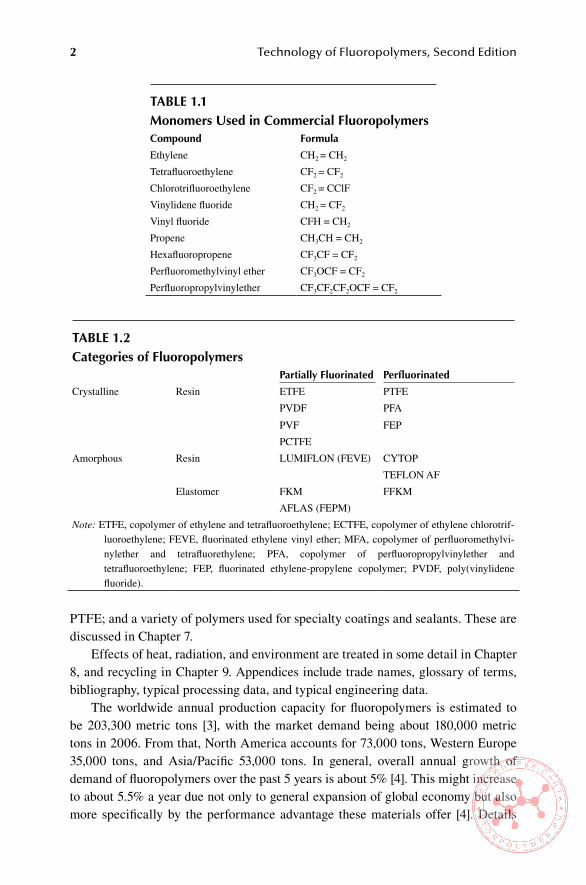
Monomers for commercially important large-volume fluoropolymers and their basic properties are shown in Table 1.1. These can be combined to yield homopoly-mers, copolymers, and terpolymers. The resulting products range from rigid resins to elastomers with unique properties not achievable by any other polymeric materials.
Several fluoropolymers have very high melting points, notably PTFE and per-fluoroalkoxy (PFA) resins; some are excellent dielectrics; and most of them exhibit a very high resistance to common solvents and aggressive chemicals. Commercial fluoropolymers with the exception of PTFE and polyvinyl fluoride (PVF) are melt-processible into films, sheets, profiles, and moldings using conventional manu-facturing methods. They are widely used in chemical, automotive, electrical, and electronic industries; in aircraft and aerospace; and in communications, construc-tion, medical devices, special packaging, protective garments, and a variety of other industrial and consumer products. Categories of commercial fluoropolymers are listed in Table 1.2.
Details about the basic chemistry and polymerization methods are included in Chapter 2; fundamental properties of the resulting products are discussed in Chapter 3, and processing and applications of thermoplastics in Chapter 4. Because fluo-roelastomers and aqueous systems have specific and different technologies from other commercial fluoropolymers, they are discussed in Chapters 5 and 6, respectively.
During the last two decades, many special fluoropolymers have been developed, such as fluorosilicones; fluorinated polyurethanes; fluorinated thermoplastic elasto-mers; new, second-generation polymers and copolymers based on PTFE; amorphous
2 Technology of Fluoropolymers, Second Edition
PTFE; and a variety of polymers used for specialty coatings and sealants. These are discussed in Chapter 7.
Effects of heat, radiation, and environment are treated in some detail in Chapter 8, and recycling in Chapter 9. Appendices include trade names, glossary of terms, bibliography, typical processing data, and typical engineering data.
The worldwide annual production capacity for fluoropolymers is estimated to be 203,300 metric tons [3], with the market demand being about 180,000 metric tons in 2006. From that, North America accounts for 73,000 tons, Western Europe 35,000 tons, and Asia/Pacific 53,000 tons. In general, overall annual growth of demand of fluoropolymers over the past 5 years is about 5% [4]. This might increase to about 5.5% a year due not only to general expansion of global economy but also more specifically by the performance advantage these materials offer [4]. Details
Table 1.1Monomers Used in Commercial FluoropolymersCompound Formula
Ethylene CH2 = CH2
Tetrafluoroethylene CF2 = CF2
Chlorotrifluoroethylene CF2 = CClF
Vinylidene fluoride CH2 = CF2
Vinyl fluoride CFH = CH2
Propene CH3CH = CH2
Hexafluoropropene CF3CF = CF2
Perfluoromethylvinyl ether CF3OCF = CF2
Perfluoropropylvinylether CF3CF2CF2OCF = CF2
Table 1.2Categories of Fluoropolymers
Partially Fluorinated Perfluorinated
Crystalline Resin ETFE PTFE
PVDF PFA
PVF FEP
PCTFE
Amorphous Resin LUMIFLON (FEVE) CYTOP
TEFLON AF
Elastomer FKM FFKM
AFLAS (FEPM)
Note: ETFE, copolymer of ethylene and tetrafluoroethylene; ECTFE, copolymer of ethylene chlorotrif-luoroethylene; FEVE, fluorinated ethylene vinyl ether; MFA, copolymer of perfluoromethylvi-nylether and tetrafluorethylene; PFA, copolymer of perfluoropropylvinylether and tetrafluoroethylene; FEP, fluorinated ethylene-propylene copolymer; PVDF, poly(vinylidene fluoride).
Introduction 3
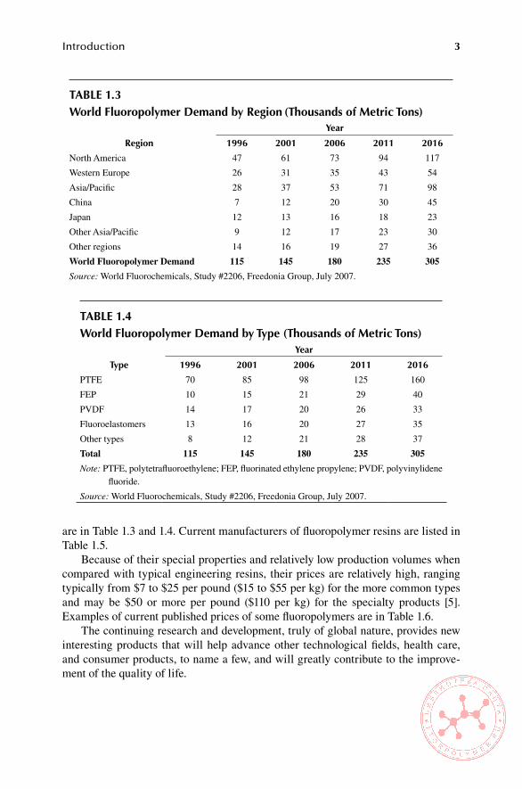
are in Table 1.3 and 1.4. Current manufacturers of fluoropolymer resins are listed in Table 1.5.
Because of their special properties and relatively low production volumes when compared with typical engineering resins, their prices are relatively high, ranging typically from $7 to $25 per pound ($15 to $55 per kg) for the more common types and may be $50 or more per pound ($110 per kg) for the specialty products [5]. Examples of current published prices of some fluoropolymers are in Table 1.6.
The continuing research and development, truly of global nature, provides new interesting products that will help advance other technological fields, health care, and consumer products, to name a few, and will greatly contribute to the improve-ment of the quality of life.
Table 1.3World Fluoropolymer Demand by Region (Thousands of Metric Tons)
Region
Year
1996 2001 2006 2011 2016
North America 47 61 73 94 117
Western Europe 26 31 35 43 54
Asia/Pacific 28 37 53 71 98
China 7 12 20 30 45
Japan 12 13 16 18 23
Other Asia/Pacific 9 12 17 23 30
Other regions 14 16 19 27 36
World Fluoropolymer Demand 115 145 180 235 305
Source: World Fluorochemicals, Study #2206, Freedonia Group, July 2007.
Table 1.4World Fluoropolymer Demand by Type (Thousands of Metric Tons)
Type
Year
1996 2001 2006 2011 2016
PTFE 70 85 98 125 160
FEP 10 15 21 29 40
PVDF 14 17 20 26 33
Fluoroelastomers 13 16 20 27 35
Other types 8 12 21 28 37
Total 115 145 180 235 305
Note: PTFE, polytetrafluoroethylene; FEP, fluorinated ethylene propylene; PVDF, polyvinylidene fluoride.
Source: World Fluorochemicals, Study #2206, Freedonia Group, July 2007.

4 Technology of Fluoropolymers, Second Edition
Table 1.5Current Major Manufacturers of Fluoropolymers
Manufacturer Products
Arkema (http://www.arkemagroup.com) PCTFE, PVDF
Asahi Glass Co. (http://www.agc.co.jp)a ETFE, FEP, PFA, FEVE, PVDF, fluorocarbon elastomers (TFE/P), PTFE, amorphous PTFE, PTFE micropowders
Central Glass Co., Ltd. (http://www.cgco.co.jp) Fluorocarbon TPE
Daikin Industries Ltd. (http://www.daikin.com), EFEP, ETFE, FEP, PCTFE, PFA, PTFE, PTFE
also Daikin America Inc. micropowders, fluorocarbon elastomers (FKM,
(http://www.daikin-america.com) fluorinated TPE), FKM latex
Dow Corning (http://www.dowcorning.com) Fluorosilicones
DuPont (http://www.dupont.com) ETFE, FEP, PFA, PTFE, amorphous PTFE, modified PTFE, PTFE micropowders, PVF, ionomers
DuPont Performance Elastomers Fluorocarbon elastomers (FKM, TFE/P, FFKMb)
(http://www. dupontelastomers.com)
Dyneon LLC (http://www.dyneon.com) ETFE, FEP, HTE fluoroplastic, THV fluoroplastic, PTFE, modified PTFE, PTFE micropowders, PFA, PVDF, fluorocarbon elastomers (FKM, FFKM)
Honeywell (http://www.honeywell.com) PCTFE
JSC Halogen (http://www.halogen.ru) PTFE, ETFE
JSC Kirovo-Chepetsk Chemical Plant (www.kckk.ru)
ETFE, FEP, PVDF, PTFE, modified PTFE,fluorocarbon elastomers (FKM)
Kureha Chemical Industry Co. Ltd. (www.kureha.co.jp)
PVDF
Momentive Performance Materials (www.momentive.com)
Fluorosilicones
Shandong Dongyue Chemical Co. PTFE
(www.dongyuechem.com)
Shin-Etsu Chemical Co., Ltd. (www.shinetsu.co.jp)
Fluorosilicones
Solvay Solexis S.p.A. (www.solwaysolexis.com)
ECTFE, MFA, PFA, PTFE, PTFE micropowders, PVDF, fluorocarbon elastomers (FKM, FFKM), FKM latex, ionomers
Zaklady Azotove (www.azoty.tarnow.pl) PTFEa U.S. subsidiary: AGC Chemicals America, Inc. (www.agcchem.com)b Products only, polymer not sold

Introduction 5
ReFeRenCes
1. Plunkett, R. J., U.S., Patent 2,230,654 (February 4, 1941) to Kinetic Chemicals Inc. 2. Miller, T. L., personal communication. 3. SRI Consulting, Inc., Chemical Economics Handbook (Menlo Park, CA, 2005). 4. Fredonia Group, World Fluorochemicals, Study 1692; World Fluoropolymer Demand,
Study 2206, Cleveland, OH (July 2007). www.freedoniagroup.com 5. Plastics Technology (http://www.ptonline.com).
Table 1.6Current Prices of selected FluoropolymersResin Price, $/Pound Price, $/Kilogram
PCTFE 50–60 110–132
ECTFE 12–16.80 26.40–37
ETFE 11.55–16.80 25.40–37
FEP 9.71–14.70 21.40–32.30
PFA 15.50–25.20 34.10–55.40
PTFE 4.50–9 9.90–14.80
PVDF 6.60–10 14.50–22
Note: ETFE, copolymer of ethylene and tetrafluoroethylene; ECTFE, copolymer of ethylene chlo-rotrifluoroethylene; PFA, copolymer of perfluoropropylvinylether and tetrafluoroethylene; PVDF, poly(vinylidene fluoride); PCTFE, poly(chlorotrifluoroethylene).
Source: Resin Pricing, October 2007, Plastics Technology (http://www.PTOnline.com).
7
2 Basic Chemistry of Fluoropolymers
The first major work in the field of fluoroolefin chemistry was that of Swarts, done near the end of the 19th century [1–3], which included the reaction
C Cl SbFSbCl
C Cl Fn n n n a a2 23
52 2+ + − →
,
where a is the number of chlorine atoms converted to fluorine atoms by the reaction. This reaction gave the early fluorine chemists a tool to prepare many fluoroalkanes. Thus, they were able to prepare a variety of chlorofluoroethanes from hexachlo-roethane. Investigators working on refrigerants used this method for the synthesis of compounds later known commercially as Freon, produced by E.I. du Pont de Nemours & Co. These materials have subsequently become precursors of most of the fluoroolefins, which represent the most important group for the manufacture of commercial fluoropolymers.
Chlorotrifluoroethylene (CTFE) was the first fluoroolefin of industrial impor-tance. The most common method of preparing it involves the dechlorination of 1,1,2-trichloro-1,2,2-trifluoroethane (commercial name Freon 113) [4]. Tetrafluo-roethylene (TFE), which is currently the most widely used monomer in the fluo-ropolymer technology, was first synthesized by Ruff and Brettschneider in 1933 by pyrolysis of tetrafluoromethane in an electric furnace [5]. Other methods to prepare TFE are from 1,2-dichlorotetrafluoroethane or 1,2-dibromotetrafluoroethane by simple dehalogenation [4]. However, the preferred commercial synthesis involves pyrolysis of dichlorodifluoromethane as described in the section on polytetrafluo-roethylene (PTFE). Hexafluoropropylene (HFP), another commercially important monomer, can by prepared by several methods, including conversion of TFE (mono-mer) under reduced pressure at 1400°C (2552°F) by passing it over a platinum wire [6] or by thermal cracking of PTFE under special conditions [7]. Fluoroolefins con-taining hydrogen are generally prepared by conventional organic processes [8]. The processes involved are discussed in detail in the sections of this chapter that follow.
2.1 PolYTeTRaFlUoRoeThYlene
2.1.1 IndustrIal synthesIs of tetrafluoroethylene
The manufacturing process of TFE consists of the following four steps:
8 Technology of Fluoropolymers, Second Edition
CaF2 + H2SO4 → CaSO4 + 2HF
CH4 + 3Cl2 → CHCl3 + 3HCl
CHCl3 + 2HF → CHClF2 + 2HCl
2CHClF2 ↔ CF2 = CF2 + 2HCl
The first step is set up to produce hydrogen fluoride (HF), and the second yields trichloromethane (chloroform). Chloroform is then partially fluorinated with hydro-gen fluoride to chlorodifluoromethane using antimony fluoride (SbF3) as a catalyst in the third step. Finally, in the fourth step, chlorodifluoromethane is subjected to pyrolysis, in which it is converted to tetrafluoroethylene. The pyrolysis is a non-catalytic gas-phase process carried out in a flow reactor at atmospheric or subatmo-spheric pressure and at temperatures 590°C to 900°C (1094°F to 1652°F) with yields as high as 95%. This last step is often conducted at the manufacturing site for PTFE because of the difficulty of handling the monomer [9].
The major by-product in this synthesis is HCl (hydrogen chloride), although a large number of halogenated products are formed, the most significant being hexafluoropropylene, perfluorocyclobutane, and 1-chloro-1,1,2,2-tetrafluoroethane, with trace amounts of others. Perfluoroisobutylene, CF2=CF2(CF3)2, one of the by-products occurring in a small amount, is very toxic. Because of the presence of a large amount of corrosive acids (HCl and HF), the reactor has to be made from highly corrosion-resistant materials (e.g., platinum-lined nickel). The use of super-heated steam as a diluent in certain proportions improves the process efficiency [10]. After pyrolysis, the cooled gas stream is scrubbed by water and alkali to remove the acids, and then it is dried by calcium chloride or sulfuric acid. Subsequently, it is compressed and subjected to refrigerated distillation to recover the unreacted chlo-rodifluoromethane and to obtain highly purified TFE.
2.1.2 ProPertIes of tetrafluoroethylene
TFE (molecular weight 100.02) is a colorless, tasteless, odorless nontoxic gas [11]. It is stored as a liquid (its vapor pressure at –20°C is 1 MPa) and polymerized usu-ally above its critical temperature of 33.3°C (91.9°F) and below its critical pressure 3.94 MPa (571 psi). The polymerization reaction is exothermic. In the absence of air it disproportionates violently to yield carbon and carbon tetrafluoride. This reac-tion generates the same amount of energy as an explosion of black powder. The decomposition is initiated thermally; therefore, the equipment used in handling and polymerization of TFE has to be without hot spots. The flammability limits are 14% to 43%; TFE burns when mixed with air and forms explosive mixtures with air and oxygen. The ignition temperature is 600°C to 800°C (1112°F to 1472°F) [12]. When stored in a steel cylinder it has to be under controlled conditions and with a suit-

Basic Chemistry of Fluoropolymers 9
able inhibitor to prevent autopolymerization. Effective inhibitors are terpenes, such as α-pinene, terpene B, and d-limonene [13], which appear to scavenge oxygen, an initiator of polymerization.
2.1.3 uses of tetrafluoroethylene
The largest proportion of TFE is used for the polymerization into a variety of PTFE homopolymers, modified PTFE, and micropowders. It is also used as comonomer in the copolymerization with hexafluoropropylene, ethylene, perfluorinated ether, and other monomers and also as a comonomer in a variety of terpolymers. Other uses of TFE are to prepare low-molecular-weight polyfluorocarbons and carbonyl fluoride oils as well as to form PTFE in situ on metal surfaces [14] and in the synthesis of hexafluoropropylene, perfluorinated ethers, and other oligomers [15].
2.1.4 PolymerIzatIon of tetrafluoroethylene
Essentially, TFE in its gaseous state is polymerized via a free radical addition mech-anism in aqueous medium with water-soluble free radical initiators, such as per-oxydisulfates, organic peroxides, or reduction–activation systems [16]. The additives have to be selected very carefully since they may interfere with the polymerization. They may either inhibit the process or cause a chain transfer that leads to inferior products. When producing aqueous dispersions, highly halogenated emulsifiers, such as fully fluorinated acids [17], are used. If the process requires normal emulsi-fiers, these have to be injected only after the polymerization has started [18]. TFE polymerizes readily at moderate temperatures (40°C to 80°C, or 104°F to 176°F) and moderate pressures (0.7 to 2.8 MPa, or 102 to 406 psi). The reaction is extremely exothermic (the heat of polymerization is 41 kcal/mol).
In principle, there are two distinct methods of polymerization of tetrafluoroeth-ylene. When little or no dispersing agent is used and the reaction mixture is agitated vigorously, a precipitated polymer is produced, commonly referred to as granular resin. If proper type and sufficient amount of dispersant are used and mild agitation is maintained, the resulting product consists of small negatively charged oval-shaped colloidal particles (longer dimension less than 0.5 μm). The two products are dis-tinctly different, even though both are high-molecular-weight PTFE polymers.
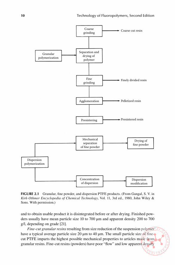
The aqueous dispersion can be used for the production of fine powders or further concentrated into products used for direct dipping, coating, and so forth (see Chapter 6). A flowchart describing the processes involved is shown in Figure 2.1, and the details pertaining to these three different products are discussed in the following section.
2.1.4.1 Granular Resins
Granular PTFE resins are produced by polymerizing tetrafluoroethylene alone or with a trace of comonomers [19,20] with initiator and sometimes in the presence of an alkaline buffer in aqueous suspension medium. The product from the autoclave can consist of a mixture of water with particles of polymer of variable size and irregular shape. After the water is removed from the mixture, the polymer is dried,
10 Technology of Fluoropolymers, Second Edition
and to obtain usable product it is disintegrated before or after drying. Finished pow-ders usually have mean particle size 10 to 700 μm and apparent density 200 to 700 g/l, depending on grade [21].
Fine-cut granular resins resulting from size reduction of the suspension polymer have a typical average particle size 20 μm to 40 μm. The small particle size of fine-cut PTFE imparts the highest possible mechanical properties to articles made from granular resins. Fine-cut resins (powders) have poor “flow” and low apparent density
Coarse cut resin
Finely divided resin
Pelletized resin
Presintered resin
Granularpolymerization
Coarsegrinding
Separation anddrying of polymer
Finegrinding
Agglomeration
Presintering
Mechanicalseparation
of fine powder
Drying offine powder
Dispersionpolymerization
Concentrationof dispersion
Dispersionmodification
FiGURe 2.1 Granular, fine powder, and dispersion PTFE products. (From Gangal, S. V. in Kirk-Othmer Encyclopedia of Chemical Technology, Vol. 11, 3rd ed., 1980, John Wiley & Sons. With permission.)
1
'
1
1
1
Basic Chemistry of Fluoropolymers 11
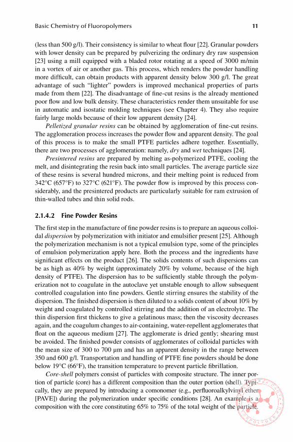
(less than 500 g/l). Their consistency is similar to wheat flour [22]. Granular powders with lower density can be prepared by pulverizing the ordinary dry raw suspension [23] using a mill equipped with a bladed rotor rotating at a speed of 3000 m/min in a vortex of air or another gas. This process, which renders the powder handling more difficult, can obtain products with apparent density below 300 g/l. The great advantage of such “lighter” powders is improved mechanical properties of parts made from them [22]. The disadvantage of fine-cut resins is the already mentioned poor flow and low bulk density. These characteristics render them unsuitable for use in automatic and isostatic molding techniques (see Chapter 4). They also require fairly large molds because of their low apparent density [24].
Pelletized granular resins can be obtained by agglomeration of fine-cut resins. The agglomeration process increases the powder flow and apparent density. The goal of this process is to make the small PTFE particles adhere together. Essentially, there are two processes of agglomeration: namely, dry and wet techniques [24].
Presintered resins are prepared by melting as-polymerized PTFE, cooling the melt, and disintegrating the resin back into small particles. The average particle size of these resins is several hundred microns, and their melting point is reduced from 342°C (657°F) to 327°C (621°F). The powder flow is improved by this process con-siderably, and the presintered products are particularly suitable for ram extrusion of thin-walled tubes and thin solid rods.
2.1.4.2 Fine Powder Resins
The first step in the manufacture of fine powder resins is to prepare an aqueous colloi-dal dispersion by polymerization with initiator and emulsifier present [25]. Although the polymerization mechanism is not a typical emulsion type, some of the principles of emulsion polymerization apply here. Both the process and the ingredients have significant effects on the product [26]. The solids contents of such dispersions can be as high as 40% by weight (approximately 20% by volume, because of the high density of PTFE). The dispersion has to be sufficiently stable through the polym-erization not to coagulate in the autoclave yet unstable enough to allow subsequent controlled coagulation into fine powders. Gentle stirring ensures the stability of the dispersion. The finished dispersion is then diluted to a solids content of about 10% by weight and coagulated by controlled stirring and the addition of an electrolyte. The thin dispersion first thickens to give a gelatinous mass; then the viscosity decreases again, and the coagulum changes to air-containing, water-repellent agglomerates that float on the aqueous medium [27]. The agglomerate is dried gently; shearing must be avoided. The finished powder consists of agglomerates of colloidal particles with the mean size of 300 to 700 μm and has an apparent density in the range between 350 and 600 g/l. Transportation and handling of PTFE fine powders should be done below 19°C (66°F), the transition temperature to prevent particle fibrillation.
Core-shell polymers consist of particles with composite structure. The inner por-tion of particle (core) has a different composition than the outer portion (shell). Typi-cally, they are prepared by introducing a comonomer (e.g., perfluoroalkylvinyl ether [PAVE]) during the polymerization under specific conditions [28]. An example is a composition with the core constituting 65% to 75% of the total weight of the particle.

12 Technology of Fluoropolymers, Second Edition
The remaining 25% to 35% of the polymer forms the shell at lower comonomer content than the core. Such resins exhibit improved paste extrudability especially in the pro-duction of tubing or wire insulation and reduced number of flaws in the final product.
2.1.4.3 aqueous Dispersions
PTFE aqueous dispersions are made by the polymerization process used to make fine powders (see Section 2.1.4.2). Raw dispersions are polymerized to different par-ticle sizes [29]. The optimum particle size for most applications is about 0.2 μm. The dispersion from the autoclave is stabilized by the addition of nonionic or anionic surfactants, followed by concentration to a solids content of 60% to 65% by electro-decantation, evaporation, or thermal concentration [30]. After further modification with chemical additives, the commercial product is sold with a polymer content of about 60% by weight, viscosity of several centipoises, and specific gravity around 1.5. The processing characteristics of the dispersion depend on the conditions for the polymerization and the type and amounts of the chemical additives contained in it. Stability is a key requirement of the final product. Typically, a PTFE aqueous disper-sion must have a shelf life of several months to 1 year. It should withstand transporta-tion and handling during processing. The shear rate during processing must be low enough as to not cause the agglomeration of the particles. Ideally, the temperature during transportation, storage, and processing should be below 19°C (66°F), for the same reason as it is in case of fine powders, namely, to prevent particle fibrillation. Processing of aqueous PTFE dispersions is discussed in more detail in Section 6.2.
2.1.4.4 Filled Resins
To improve the properties of the raw polymer (wear resistance, creep resistance, thermal and electrical conductivity), various fillers, such as glass fibers, powdered metals, and graphite, are combined with all three types of PTFE polymers, mostly by intimate mixing. Filled fine powders are produced mostly by adding fillers into a dispersion and then coagulating the mixture. Aqueous dispersions can also be modi-fied by the addition of certain fillers, pigments, heat resistant dyes, carbon blacks, and powdered metals, especially when processed into films (see Chapter 6).
2.1.4.5 PTFe Micropowders
PTFE micropowder,s also referred to as fluoroadditives, are homopolymer grades of PTFE with a considerably lower molecular weight than standard PTFE. They are produced either by controlled suspension or dispersion polymerization to a lower molecular weight [31,32] or by degradation of PTFE scrap by thermal cracking (pyrolysis) or by irradiation by high-energy electron beam (EB). The electron beam process is the most widely used commercial method [33]. Micropowders are white, free-flowing powders with very small particle size (typically in the range 2–20 μm). They have different particle shapes and morphology from those of granular and fine powder grades of PTFE [31]. The molecular weight of micropowders is in the range 104 to 105 compared with that of standard PTFE, which is typically in the range 106 to 107. The melt viscosity of micropowders ranges from 102 to 105 Poise,

Basic Chemistry of Fluoropolymers 13
considerably lower than the typical values of standard PTFE of 109 to 1011 [31]. They are used predominantly as additives to lubricants to improve their performance and to plastics and rubber to reduce their coefficient of friction, and as additives to printing inks and coatings to reduce their nonstick properties [34]. The subject of micropowders is covered in greater detail in Chapter 7.
2.1.4.6 Modified PTFe
Modified PTFE represents a relatively new technology that is designed to overcome the limitations of conventional PTFE, namely, poor creep resistance (i.e., tendency to cold flow), difficult welding, and high level of microvoids [35]. These changes of properties are accomplished by addition of small amount comonomer in amounts less than 0.1%. Such modifier is most frequently perfluoropropylvinyl ether (PPVE). The copolymerization is carried out in aqueous suspension under practically the same conditions as the homopolymerization of tetrafluoroethylene, that is, at TFE pressures in the range 5 to 20 bar (72 to 290 psi) and temperature range 35°C to 90°C (95°F to 194°F) [36]. There is more on modified PTFE in Section 7.7.
2.2 FlUoRinaTeD eThYlene PRoPYlene (FeP)
Fluorinated ethylene propylene is a copolymer of TFE and hexafluoropropylene and has a branched structure containing units of –CF2–CF2– and –CF2–CF (CF3)–. It retains most of the favorable properties of PTFE, but its melt viscosity is low enough for conventional melt processing. The introduction of HFP reduces the melting point of polytetrafluoroethylene from 327°C (621°F) to about 260°C (500°F) [37].
2.2.1 IndustrIal synthesIs of hfP
There are several methods to produce HFP. For example, thermal cracking of TFE at reduced pressure and temperatures 700°C to 800°C (1292°F to 1472°F) produces HFP in high yield [38,39]. Another process is pyrolysis of polytetrafluoroethylene under vacuum at 860°C (1580°F) with a 58% yield [40]. More recently, a technique involves the pyrolysis of a mixture of tetrafluoroethylene and carbon dioxide at atmospheric pressure and temperatures 700°C to 900°C (1292°F to 1652°F) [41]. Additional routes to HFP are described in [42,43].
2.2.2 ProPertIes of hfP
HFP does not polymerize into a homopolymer easily; therefore, it can be stored as a liquid. However, it forms industrially useful copolymers and terpolymers with other fluorinated monomers. Oxidation of HFP yields an intermediate for a number of perfluoroalkyl perfluorovinyl ethers [43].
HFP is thermally stable up to 400°C to 500°C (752°F to 932°F). At about 600°C (1112°F) under vacuum, HFP decomposes and produces octafluoro-2-butene (CF3=CFCF3) and octafluoroisobutylene [44]. Under basic conditions, hydrogen per-oxide reacts with HFP to form hexafluoropropylene epoxide, which is an intermediate in the preparation of perfluoroalkylvinyl ethers [45,46]. Hexafluoropropylene readily
14 Technology of Fluoropolymers, Second Edition
reacts with hydrogen, chlorine, and bromine (but not with iodine) by an addition reac-tion similar to other olefins. Similarly HF, HCl, and hydrogen bromide (HBr) (but not hydrogen iodide [HI]) add to HFP [47].
2.2.3 IndustrIal Process for the ProductIon of feP
There are several methods of copolymerization of hexafluoropropylene and tetra-fluoroethylene using different catalysts at different temperatures [48–50]. Aqueous and nonaqueous dispersion polymerizations appear to be the most convenient com-mercial routes. The conditions for this type of process are similar to those for the dispersion homopolymerization of TFE. FEP is a random copolymer; that is, HFP units add to the growing chain at random intervals. The optimal composition of the copolymer is such that the mechanical properties are retained in the usable range and that it has low enough melt viscosity for an easy melt processing [51]. Commercial FEP is available as low-melt-viscosity grades for injection molding, grades for extru-sion, medium-viscosity grades, high-viscosity grades, and aqueous dispersions with 55% solids by weight [51,52].
2.3 PeRFlUoRoalKoxY (PFa) Resin
2.3.1 IndustrIal synthesIs of Perfluoroalkyl VInyl ether monomers
The classic process involves the chemistry of fluorocarbon epoxides. Its initial step is a catalytic oxidation of HFP into a fluoroepoxide. The fluoroepoxide is then reacted with a metal fluoride to obtain an acid fluoride, which is then pyrolyzed over calcium carbonate at 250°C (482°F) to obtain propylvinyl ether (PVE) [53,54].
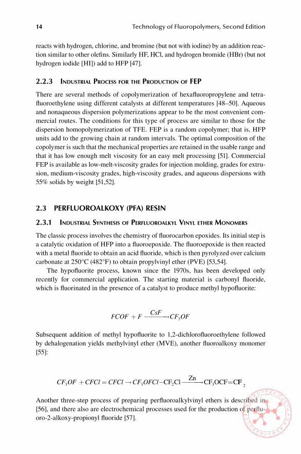
The hypofluorite process, known since the 1970s, has been developed only recently for commercial application. The starting material is carbonyl fluoride, which is fluorinated in the presence of a catalyst to produce methyl hypofluorite:
FCOF F CsF CF OF+ → 3
Subsequent addition of methyl hypofluorite to 1,2-dichlorofluoroethylene followed by dehalogenation yields methylvinyl ether (MVE), another fluoroalkoxy monomer [55]:
CF OF CFCl CFCl CF OFCl3 3+ = → − → =CF Cl Zn CF OCF C2 3 FF
2
Another three-step process of preparing perfluoroalkylvinyl ethers is described in [56], and there also are electrochemical processes used for the production of perflu-oro-2-alkoxy-propionyl fluoride [57].
Basic Chemistry of Fluoropolymers 15
2.3.2 ProPertIes of PerfluoroalkylVInyl ethers
Perfluoroalkylvinyl ethers form an important class of monomers in that they are used as comonomers for the modification of the properties of homofluoropolymers in addition to their broad use in copolymers with TFE and other monomers. They are capable of suppressing the crystallization of PTFE efficiently, which imparts useful mechanical properties to lower molecular weight of polytetrafluoroethylene polymers. Copolymers of PAVEs and tetrafluoroethylene are thermally stable as PTFE homopolymers. Commercially significant monomers are perfluoropropylvinyl ether and perfluoromethylvinyl ether (PMVE), used for the production of a variety of perfluoroalkoxy resins.
2.3.3 IndustrIal Process for the ProductIon of Perfluoroalkoxy resIns
Perfluoroalkoxy resins are prepared by copolymerization of TFE and perfluoroalkyl monomers in either aqueous or nonaqueous media [58–60].
In aqueous copolymerization, which has similar reaction conditions to emulsion polymerization of PTFE, inorganic peroxy compounds (e.g., ammonium persulfate) are used as initiators, and also a perfluorinated emulsifying agent (e.g., ammonium perfluorooctanoate) is added [61].
In a nonaqueous copolymerization, fluorinated acyl peroxides are added that are soluble in the medium [62]. A chain transfer agent may be added to control the molecular weight of the resin. The polymer is separated from the medium and con-verted into useful forms such as melt-extruded cubes for processes working with melt (e.g., extrusion, injection molding). The resins are also available as aqueous dispersions, molding powders, and fine powders for powder coating [63,64].
2.4 PolYChloRoTRiFlUoRoeThYlene (PCTFe)
2.4.1 IndustrIal synthesIs of chlorotrIfluoroethylene monomer
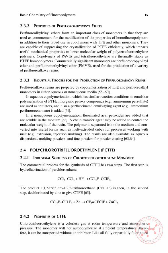
The commercial process for the synthesis of CTFE has two steps. The first step is hydrofluorination of perchloroethane:
CCl3–CCl3 + HF → CCl2F–CClF2
The product 1,1,2-trichloro-1,2,2-trifluoroethane (CFC113) is then, in the second step, dechlorinated by zinc to give CTFE [65].
CCl2F–CCl F2 + Zn → CF2=CFClF + ZnCl2
2.4.2 ProPertIes of ctfe
Chlorotrifluoroethylene is a colorless gas at room temperature and atmospheric pressure. The monomer will not autopolymerize at ambient temperatures; there-fore, it can be transported without an inhibitor. Like all fully or partially fluorinated

16 Technology of Fluoropolymers, Second Edition
ethylenes, CTFE can undergo a disproportionation reaction and thus must be han-dled properly. It forms high-molecular peroxides in reaction with oxygen, and these can precipitate from solution. Thus, oxygen concentration of commercial CTFE is maintained below 50 ppm [66]. CTFE hydrolyzes slowly in water containing oxy-gen, whereas it is completely stable in degassed water. It is used for preparation of a homopolymer (polychlorotrifluoroethylene [PCTF]) and as a comonomer to a vari-ety of copolymers.
2.4.3 IndustrIal Process for the ProductIon of Pctfe
Commercial process for the production of PCTFE is essentially polymerization initi-ated by free radicals at moderate temperatures and pressures in an aqueous system at low temperatures and moderate pressures. It is reported that it is possible to polymer-ize CTFE in bulk, solution, suspension, and emulsion. According to some reports the emulsion system produces the most stable polymer [65]. The tendency of PCTFE to become brittle during use can be reduced by incorporating a small amount (less than 5%) of vinylidene fluoride (VDF) during the polymerization process [67].
2.5 PolYvinYliDene FlUoRiDe (PvDF)
2.5.1 IndustrIal synthesIs of VInylIdene fluorIde monomer
One process to produce VDF starts with acetylene, which reacts with 2 mol of hydrogen fluoride using a Lewis acid (BF3) as catalyst giving 1,1-difluoroethane (CFC152) [68]:
CH CH+2HF CH CHFBF3 2
3≡ →
CFC152 is then chlorinated to 1-chloro-1,1-difluoroethane (CFC142) [69]:
CH3CHF2 + Cl2 → CH3CClF2 + HCl
Subsequently, CFC142 is dehydrochlorinated, yielding vinylidene fluoride [70]:
CH3CClF2 → CH2=CF2 + HCl
Another, somewhat different process, starts from 1,1,1-trichloroethane, which after dehydrochlorination gives CFC142. The second step, dehydrochlorination of CFC142, is the same. The dehydrochlorination may be done either thermally or catalytically. At any rate, the production equipment has to be made from a highly corrosion-resistant material [71].
Catalytic pyrolysis, which is described in [72,73], starts from 1,1,1-trifluoro-ethane and yields VDF at high conversion and purity.
Basic Chemistry of Fluoropolymers 17
2.5.2 ProPertIes of VInylIdene fluorIde
Vinylidene fluoride is a colorless gas at ambient temperature and pressure. It is flam-mable and can form explosive mixtures with air.
VDF is used either for the production of homopolymer or as a comonomer for a number of fluorinated monomers (HFP, TFE, CTFE) for the production of fluoro-plastics and fluoroelastomers.
2.5.3 IndustrIal Process for the ProductIon of PVdf
The most common methods of producing homopolymers and copolymers of vinylidene fluoride are emulsion and suspension polymerizations, although other methods are also used [74].
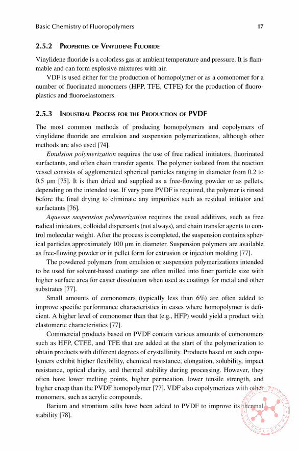
Emulsion polymerization requires the use of free radical initiators, fluorinated surfactants, and often chain transfer agents. The polymer isolated from the reaction vessel consists of agglomerated spherical particles ranging in diameter from 0.2 to 0.5 μm [75]. It is then dried and supplied as a free-flowing powder or as pellets, depending on the intended use. If very pure PVDF is required, the polymer is rinsed before the final drying to eliminate any impurities such as residual initiator and surfactants [76].
Aqueous suspension polymerization requires the usual additives, such as free radical initiators, colloidal dispersants (not always), and chain transfer agents to con-trol molecular weight. After the process is completed, the suspension contains spher-ical particles approximately 100 μm in diameter. Suspension polymers are available as free-flowing powder or in pellet form for extrusion or injection molding [77].
The powdered polymers from emulsion or suspension polymerizations intended to be used for solvent-based coatings are often milled into finer particle size with higher surface area for easier dissolution when used as coatings for metal and other substrates [77].
Small amounts of comonomers (typically less than 6%) are often added to improve specific performance characteristics in cases where homopolymer is defi-cient. A higher level of comonomer than that (e.g., HFP) would yield a product with elastomeric characteristics [77].
Commercial products based on PVDF contain various amounts of comonomers such as HFP, CTFE, and TFE that are added at the start of the polymerization to obtain products with different degrees of crystallinity. Products based on such copo-lymers exhibit higher flexibility, chemical resistance, elongation, solubility, impact resistance, optical clarity, and thermal stability during processing. However, they often have lower melting points, higher permeation, lower tensile strength, and higher creep than the PVDF homopolymer [77]. VDF also copolymerizes with other monomers, such as acrylic compounds.
Barium and strontium salts have been added to PVDF to improve its thermal stability [78].
18 Technology of Fluoropolymers, Second Edition
2.6 PolYvinYl FlUoRiDe (PvF)
2.6.1 IndustrIal synthesIs of VInyl fluorIde (Vf) monomer
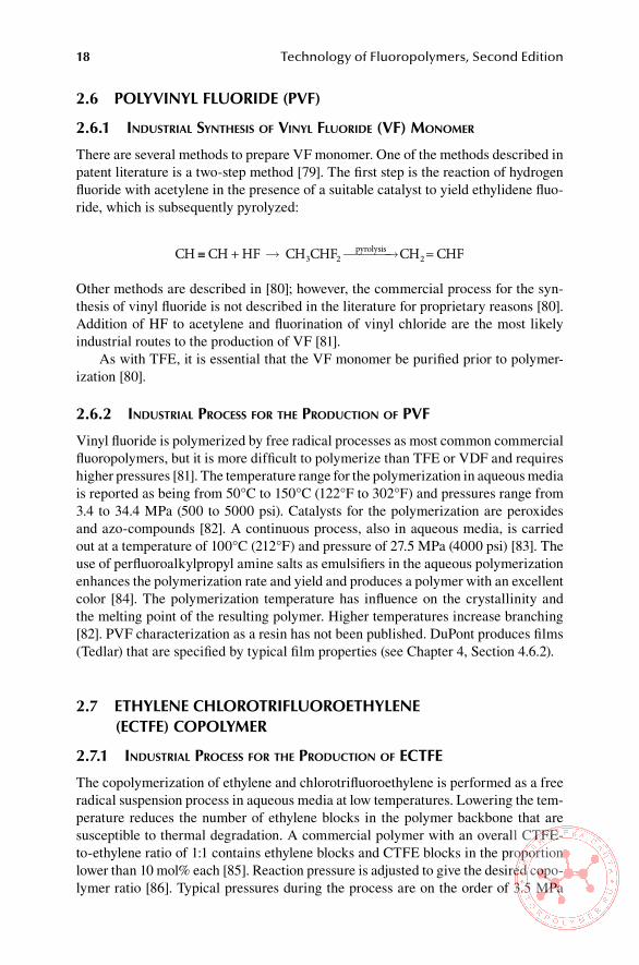
There are several methods to prepare VF monomer. One of the methods described in patent literature is a two-step method [79]. The first step is the reaction of hydrogen fluoride with acetylene in the presence of a suitable catalyst to yield ethylidene fluo-ride, which is subsequently pyrolyzed:
CH CH+HF CH CHF CH =CHF3 2pyrolysis
2≡ → →
Other methods are described in [80]; however, the commercial process for the syn-thesis of vinyl fluoride is not described in the literature for proprietary reasons [80]. Addition of HF to acetylene and fluorination of vinyl chloride are the most likely industrial routes to the production of VF [81].
As with TFE, it is essential that the VF monomer be purified prior to polymer-ization [80].
2.6.2 IndustrIal Process for the ProductIon of PVf
Vinyl fluoride is polymerized by free radical processes as most common commercial fluoropolymers, but it is more difficult to polymerize than TFE or VDF and requires higher pressures [81]. The temperature range for the polymerization in aqueous media is reported as being from 50°C to 150°C (122°F to 302°F) and pressures range from 3.4 to 34.4 MPa (500 to 5000 psi). Catalysts for the polymerization are peroxides and azo-compounds [82]. A continuous process, also in aqueous media, is carried out at a temperature of 100°C (212°F) and pressure of 27.5 MPa (4000 psi) [83]. The use of perfluoroalkylpropyl amine salts as emulsifiers in the aqueous polymerization enhances the polymerization rate and yield and produces a polymer with an excellent color [84]. The polymerization temperature has influence on the crystallinity and the melting point of the resulting polymer. Higher temperatures increase branching [82]. PVF characterization as a resin has not been published. DuPont produces films (Tedlar) that are specified by typical film properties (see Chapter 4, Section 4.6.2).
2.7 eThYlene ChloRoTRiFlUoRoeThYlene (eCTFe) CoPolYMeR
2.7.1 IndustrIal Process for the ProductIon of ectfe
The copolymerization of ethylene and chlorotrifluoroethylene is performed as a free radical suspension process in aqueous media at low temperatures. Lowering the tem-perature reduces the number of ethylene blocks in the polymer backbone that are susceptible to thermal degradation. A commercial polymer with an overall CTFE-to-ethylene ratio of 1:1 contains ethylene blocks and CTFE blocks in the proportion lower than 10 mol% each [85]. Reaction pressure is adjusted to give the desired copo-lymer ratio [86]. Typical pressures during the process are on the order of 3.5 MPa

Basic Chemistry of Fluoropolymers 19
(508 psi). In some cases modifying monomers are added to reduce high-temperature stress cracking of the pure ECTFE copolymer. The modified products typically have a lower degree of crystallinity and lower melting points [85].
During the copolymerization the product precipitates as a fine powder, with particles typically less than 20 μm in major dimension. These particles eventually agglomerate into roughly spherical beads, and the reactor product is a mixture of beads and powder. The product is then dewatered and dried. It is further processed into extruded pellets for melt processing (e.g., extrusion, injection molding, blow molding) or ground and screened into powder coating grades [87]. Additional methods of copolymerization of ethylene and CTFE are discussed in [88].
2.8 eThYlene TeTRaFlUoRoeThYlene (eTFe) CoPolYMeR
2.8.1 IndustrIal Process for the ProductIon of etfe
Commercial products based on copolymers of ethylene and TFE are made by addi-tion copolymerization initiated by free radicals [89]. Small amounts (1 to 10 mol%) of modifying comonomers are added to eliminate a rapid embrittlement of the prod-uct at exposure to elevated temperatures. Examples of the modifying comonomers are perfluorobutylethylene, hexafluoropropylene, perfluorovinyl ether, and hexafluor-oisobutylene [90]. Additional information on the methods to prepare ETFE copoly-mers are discussed in [88]. ETFE resins are essentially alternating copolymers [90], and in the molecular formula they are isomeric with PVDF with a head-to-head, tail-to-tail structure. However, in many important physical properties, the modified ETFE copolymers are superior to PVDF with the exception of the latter’s remarkable piezoelectric and pyroelectric characteristics.
2.9 TeRPolYMeRs oF TFe, hFP, anD vDF (Thv FlUoRoPlasTiC)
Tetrafluoroethylene, hexafluoropropylene, and vinylidene (THV) fluoroplastic is pre-pared by emulsion copolymerization. The resulting dispersion may be used directly or may be concentrated with the addition of an emulsifier. If it is coagulated, washed, and dried, the final products are either powders (after grinding) or pellets (after extrusion and pelletizing). No additives are added to the polymer since the product is inherently very stable and easy to process [91]. At this writing, Dyneon Company is producing two types of commercial grades of THV fluoroplastic, namely, dry products and an aqueous dispersion differing in monomer ratio, which affects the melting points, chemical resistance, and flexibility [91]. Because they contain VDF monomeric unit, they are cross-linkable by electron beam; one grade is soluble in common solvents.

20 Technology of Fluoropolymers, Second Edition
2.10 TeRPolYMeRs oF hFP, TFe, anD eThYlene (hexaFlUoRoPRoPYlene, TeTRaFlUoRoeThYlene, anD eThYlene FlUoRoPlasTiC)
These polymers are prepared by emulsion polymerization of ethylene, TFE, and HFP [92]. They may have, for example, ethylene monomeric units in a range of from at least about 2%, 10%, or 20% by weight up to 30%, 40%, or even 50% by weight, and HFP monomeric units in a range of from at least about 5%, 10%, or 15% by weight up to about 20%, 25%, or even 30% by weight, with the remainder of the weight of the polymer being TFE monomeric units [93]. At this writing, Dyneon is marketing two grades, namely, Dyneon Fluoroplastic terpolymer of hexafluoropropylene, tetra-fluroethylene, and ethylene (HTE) 1510 and HTE 1705.
2.11 FlUoRoCaRbon elasToMeRs
The first commercial fluoroelastomer, Kel-F, was developed by the M.W. Kellog Company in the early to mid-1950s and is a copolymer of VDF and CTFE. Another fluorocarbon elastomer, Viton A, is a copolymer of VDF and HFP developed by DuPont was made available commercially in 1955. The products developed there-after can be divided into two classes: VDF-based fluoroelastomers and TFE-based fluoroelastomers (perfluoroelastomers) [94]. Current products are mostly based on copolymers of VDF and HFP, VDF, and MVE or on terpolymers of VDF with HFP and TFE. In the combination of VDF and HFP, the proportion of HFP has to be in the range from 19 to 20 mol% or higher to obtain amorphous elastomeric product [95]. The ratio of VDF/HFP/TFE also has to be within a certain region to yield elas-tomers, as shown in a triangular diagram (Figure 2.2) [96].
HFP
80
60
40
20
80 60 40 20
20
40
60
80
HFP by
Weig
ht
VF2 b
y Weig
ht
Elastomericregion
TFE VF2TFE by Weight
FiGURe 2.2 Compositions of VDF/HFP/TFE. (From Scheirs, J. (Ed.), Modern Fluoropo-lymers, John Wiley & Sons, 1997. With permission.)

Basic Chemistry of Fluoropolymers 21
2.11.1 IndustrIal Process for the ProductIon of fluorocarbon elastomers
Fluorocarbon elastomers are generally prepared by high-pressure, free radical emul-sion polymerization [97]. Organic or inorganic peroxy-compounds, such as ammo-nium persulfate, are used as initiators. Inorganic initiators generally produce ionic chain ends, such as –CH2OH and –CF2COOH, which contribute to the colloidal stability of the latex formed during the polymerization [98]. In this case, suitable emulsifiers, such as ammonium perfluorooctoate, are not strictly required [99]. The ionic chains derived from the polymerization initiators also have important effects on the properties of the resulting polymer, such as rheology, mechanical properties, and even sealing properties [98]. Chain transfer agents, such as carbon tetrachloride, methanol, and acetone dodecylmercaptane, are used to control the molecular weight of the polymer. Optionally, a cure-site monomer (CSM) may be added. The polym-erization may be either a semibatch [100] or a continuous process [101]. Figure 2.3 is a schematic of the general process. The resulting latex is most frequently coagulated into a crumb by adding salt or acid or a combination of both or by a freeze–thaw process. The crumb is filtered and washed to remove coagulant and water-soluble residues and then is washed and dried. The finished product is supplied as pellets, lumps, or milled sheets [101]. Some fluoroelastomers are also available in latex form. The detailed description of the production of fluorocarbon elastomers, including alternative methods of polymerization, is described in [102].
2.12 FlUoRosiliCones
There are a variety of compounds containing the combination of silicon and fluo-rine. However, only fluorinated polymers with a siloxane backbone are currently available commercially.
Reactor
Monomers torecovery/recycle
Degasser/dispersionblender Aqueous solution
Polymer topackaging or
precompounding
Water vapor
IsolationCompressor
Monomers
WaterInitiator
SoapChain
transfer agentCure-site
monomer
FiGURe 2.3 General process to produce fluorocarbon elastomers (From Moore, A. L., Fluoroelastomers Handbook, William Andrew Publishing, 2006. With permission.)
22 Technology of Fluoropolymers, Second Edition
The original and by far the most widely available fluorosilicone since its intro-duction in the 1950s is polymethyltrifluoropropylsiloxane (PMTFPS), more rigor-ously known as poly[methyl(3,3,3-trifluoropropyl)siloxane] or poly[methyl(1H,1H, 2H,2H-trifluoropropyl)siloxane]. Unless specifically mentioned, the unfluorinated carbons are those nearest to silicon—that is, polymethylnonafluorohexylsiloxane (PMNFHS) is poly[methyl(1H,1H,2H,2H-nonafluorohexyl)siloxane]. Currently, only copolymers of PMTFPS and PMNFHS with polydimethylsiloxane (PDMS) are available commercially [103].
2.12.1 IndustrIal Process for the ProductIon of fluorosIlIcones
Hydrosilylation is by far the most important route for obtaining monomers and other precursors to fluorinated polysiloxanes. Hydrosylilation [104] is the addition of sili-con hydride moiety across an unsaturated linkage using transition metal complexes of platinum or rhodium such as Speier’s catalyst, hexachloroplatinic acid in isopro-panol [103]. The preparation of methyl(3,3,3-trifluoropropyl)dichlorosilane, which is the precursor of the industrially most important PMTFPS, is described in patent literature [105].
The most common route for the preparation of PMTFS is through the base- catalyzed ring-opening polymerization of the cyclic trimer, which is obtained through hydrolysis of the corresponding dichlorosilane. Copolymers are prepared by the same polymerization technique [108].
Details about chemistry and processes pertaining to the manufacture of fluoro-silicones are found in [107].
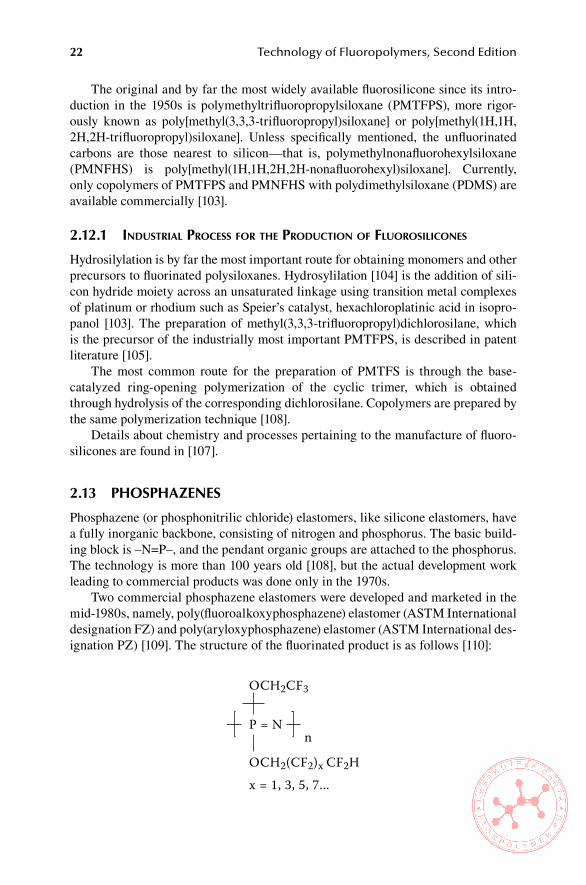
2.13 PhosPhazenes
Phosphazene (or phosphonitrilic chloride) elastomers, like silicone elastomers, have a fully inorganic backbone, consisting of nitrogen and phosphorus. The basic build-ing block is –N=P–, and the pendant organic groups are attached to the phosphorus. The technology is more than 100 years old [108], but the actual development work leading to commercial products was done only in the 1970s.
Two commercial phosphazene elastomers were developed and marketed in the mid-1980s, namely, poly(fluoroalkoxyphosphazene) elastomer (ASTM International designation FZ) and poly(aryloxyphosphazene) elastomer (ASTM International des-ignation PZ) [109]. The structure of the fluorinated product is as follows [110]:
OCH2CF3
OCH2(CF2)x CF2Hx = 1, 3, 5, 7...
P = Nn

Basic Chemistry of Fluoropolymers 23
In general, the synthesis of polyphosphazene polymers is unique in that, in the-ory, an infinite number of polymers with a variety of properties can be derived from the common polymeric intermediate, poly(dichlorophosphazene) (PNCl2), by replac-ing the chlorines with different nucleophiles. If the polydichlorophosphazene pre-cursor is reacted with the sodium salts of trifluoroethanol and a mixed fluorotelomer alcohol, a poly(fluoroalkoxyphosphazene) elastomer (FZ elastomer) is obtained. It contains a small amount of an unsaturated substituent as a curing site. The polymer is a soft gum, which can be compounded with carbon blacks and fillers and cured with sulfur or peroxides or by radiation.
FZ elastomer offers a broad service temperature range, namely, from –65°C to 175°C (–85°F to 347°F) [110], excellent flex fatigue resistance, damping properties, and resistance to chemicals and fluids.
Phosphazene elastomers were very successful throughout the 1980s, being used mainly in military and aerospace industry. However, because of their high cost and relatively small volume market, they are not available commercially other than on special orders.
ReFeRenCes
1. Swarts, F., Bull. Acad. Roy. Bel. 24 (3), p. 474 (1892). 2. Swarts, F., Bull. Acad. Roy. Bel. 29 (3), p. 874 (1895). 3. Swarts, F., Centralblat 1, p. 3 (1903). 4. Fearn, J. E. in Fluoropolymers (Wall, L. A., Ed.), Wiley-Interscience, New York, p. 3
(1972). 5. Ruff O. and Brettschneider, O., Z. Anorg. Allgem. Chem. 210, p. 173 (1933). 6. Benning, A. F. Downing, F.B., and Park, J.D., U.S. Patent 2,394,581 (February 12,
1946) to Kinetic Chemical. 7. Downing, F. B., Benning, A.F., U.S. Patent 2,480,560 (August 30, 1949) to Kinetic
Chemical. 8. Wall, L. A. (Ed.), Fluoropolymers, Wiley-Interscience, New York, p. 4 (1972). 9. Gangal, S. V. in Kirk-Othmer: Encyclopedia of Chemical Technology, Vol.11, Third
Edition, John Wiley & Sons, New York, p. 2 (1980). 10. Gangal, S. V. in Encyclopedia of Polymer Science and Technology, Vol.16 (Mark, H. F.
and Kroschwitz, J. I., Eds.), John Wiley & Sons, New York, p. 579 (1989). 11. Sheratt, S. in Encyclopedia of Chemical Technology, Vol. 9, John Wiley & Sons, New
York, p. 808 (1966). 12. Sheratt, S. in Encyclopedia of Chemical Technology, Vol. 9, John Wiley & Sons, p. 809
(1966). 13. Dietrich, M.A., and Joyce, R.M., U.S. Patent 2,407, 405 (September 10, 1946), to E.I. du
Pont de Nemours & Co. 14. Toy, M. S. and Tiner, N.A., U.S. Patent 3,567,521 (March 2, 1971) to McDonnell Doug-
las Co. 15. Gangal, S. V. in Encyclopedia of Polymer Science and Technology, Vol.16 (Mark, H. F.
and Kroschwitz, J. I., Eds.), John Wiley & Sons, New York, p. 579 (1989). 16. Sheratt, S. in Encyclopedia of Chemical Technology, Vol. 9, John Wiley & Sons, New
York, p. 812 (1966). 17. Berry, K. L., U.S. Patent 2,559,752 (July 10, 1951 to E.I. du Pont de Nemours & Co. 18. Duddington, J. E. and Sheratt, S., U.S. Patent 3,009,892 (November 21, 1961) to Impe-
rial Chemical Industries Ltd.

24 Technology of Fluoropolymers, Second Edition
19. Doughty, T. R. Russell, T., Sperati, C.A., and Ho-Wei Un, H., U.S. Patent 3,855,191 (December 17, 1974) E.I. du Pont de Nemours & Co.
20. Mueller, M. B., Salatello, P.P., and Kaufman, H.S. U.S. Patent 3,655,611 (April 11, 1972) to Allied Chemicals.
21. Sheratt, S. in Encyclopedia of Chemical Technology, Vol. 9, John Wiley & Sons, New York, p. 813 (1966).
22. Ebnesajjad, S., Fluoroplastics, Vol.1, Non-Melt Processible Fluoroplastics, William Andrew Publishing, Norwich, NY, 2000, p. 36.
23. Thomas, P.E., and Wallace, Jr. C.C., U.S. Patent 2,936,301 (April 10, 1960), to E.I. du Pont de Nemours & Co.
24. Ebnesajjad, S., Fluoroplastics, Vol.1, Non-Melt Processible Fluoroplastics, William Andrew Publishing, Norwich, NY, 2000, p. 37.
25. Bankoff, S. G., U.S. Patent 2,612,484 (September 30, 1952) E.I. du Pont de Nemours & Co.
26. Gangal, S. V. in Encyclopedia of Polymer Science and Technology, Vol.16 (Mark, H. F. and Kroschwitz, J. I., Eds.), John Wiley & Sons, New York, p. 581 (1989).
27. Sheratt, S. in Encyclopedia of Chemical Technology, Vol. 9, John Wiley & Sons, New York, p. 814 (1966).
28. Ebnesajjad, S., Fluoroplastics, Vol.1, Non-Melt Processible Fluoroplastics, William Andrew Publishing, Norwich, NY, 2000, p. 43
29. Gangal, S. V., U.S. Patent 4,342,675 (August 3, 1982) to E.I. du Pont de Nemours & Co.
30. Berry, K. L., U.S. Patent 2,478,229 (August 9, 1949) to E.I. du Pont de Nemours & Co. 31. Ebnesajjad, S., Fluoroplastics, Vol.1, Non-Melt Processible Fluoroplastics, William
Andrew Publishing, Norwich, NY, 2000, p. 191. 32. Mayer. L., Tonnes, K.-U., and Bladel, H., U.S. Patent 5,641,571 (June 14, 1997), to
Hoechst, A.G. 33. Ebnesajjad, S., Fluoroplastics, Vol.1, Non-Melt Processible Fluoroplastics, William
Andrew Publishing, Norwich, NY, 2000, p. 193. 34. Ebnesajjad, S., Fluoroplastics, Vol.1, Non-Melt Processible Fluoroplastics, William
Andrew Publishing, Norwich, NY, 2000, Chapter 11. 35. Hintzer, K., and Löhr, G., in Modern Fluoropolymers: High Performance Polymers for
Diverse Applications (Scheirs, J., Ed.), John Wiley & Sons Ltd., Chichester, U.K., 1997, p. 239.
36. Hintzer, K., and Löhr, G., in Modern Fluoropolymers: High Performance Polymers for Diverse Applications (Scheirs, J., Ed.), John Wiley & Sons Ltd., Chichester, U.K., 1997, p. 240.
37. Gangal, S. V. in Encyclopedia of Polymer Science and Technology, Vol.16 (Mark, H. F. and Kroschwitz, J. I., Eds.), John Wiley & Sons, New York, p. 601 (1966).
38. Nelson, D.A., U.S. Patent 3,758,138 (August 7, 1956). 39. Atkinson, B. and Trenwith, A.B., J. Chem.Soc., Pt II, p. 2082 (1953). 40. Wadell, J.S., U.S. Patent 2,759,783 (August 21, 1956) to E.I. du Pont de Nemours &
Co. 41. Ebnesajjad, S., Fluoroplastics, Vol.1, Non-Melt Processible Fluoroplastics, William
Andrew Publishing, Norwich, NY, 2000, p. 27. 42. Renfrew, M.M., U.S. Patent 2,434,058 (December 12, 1950) to E.I. du Pont de Nemours
& Co. 43. Gangal, S. V. in Encyclopedia of Polymer Science and Technology, Vol.16 (Mark, H. F.
and Kroschwitz, J. I., Eds.), John Wiley & Sons, New York, p. 602 (1966). 44. Banham, J., and Browning, H.E., U.S. Patent 3,983,200 (April 6, 1975) to Imperial
Chemical Industries, Ltd.

Basic Chemistry of Fluoropolymers 25
45. Harris, Jr., J.F., and McCrane, D.I., U.S. Patent 3,180,895 (April 27, 1965), to E.I. DuPont de Nemours & Co.
46. Fritz, G.G., and Selman S., U.S. patent 3,291,843 (December 13, 1966) to E.I. du Pont de Nemours & Co.
47. Ebnesajjad, S., Fluoroplastics, Vol.1, Non-Melt Processible Fluoroplastics, William Andrew Publishing, Norwich, NY, 2000, p. 28.
48. Miller, W. T., U.S. Patent 2,598,283 (May 27, 1952) to U.S. Atomic Energy Commission.
49. Naberezhnykh, R. A., Sorokin, A.D., Volova, E.V., and Fokin, A.V., Dokl. Akad. Nauk SSSR 214, p.149 (1974).
50. Kabankin, A. S. , Balabanova, S.A., and Markevich, A.M., Vysokomol. Soed. Ser. A 12, p.267 (1970).
51. Gangal, S. V. in Encyclopedia of Polymer Science and Technology, Vol.16 (Mark, H. F. and Kroschwitz, J. I., Eds.), John Wiley & Sons, p. 603 (1989).
52. Gangal, S.V. in Encyclopedia of Chemical Technology 3rd Edition, Vol. 11 (Grayson, M, Ed.), John Wiley & Sons, New York, 1978, p. 24
53. Fritz, C. G., Moore, Jr., E.P. and Selman, S., U.S. Patent 3,114,778 (1963) to E.I. du Pont de Nemours & Co.
54. Moore, E. P., U.S. Patent 3,322,826 (1967) to E.I. du Pont de Nemours & Co. 55. Pozzoli, M., Vitta, G. and Arcella, V. in Modern Fluoropolymers (Scheirs, J., Ed.) John
Wiley & Sons, Ltd, Chichester, UK, 1997, p. 377. 56. Ebnesajjad, S., Fluoroplastics, Vol.1, Non-Melt Processible Fluoroplastics, William
Andrew Publishing, Norwich, NY, 2000, p. 29. 57. Brice, T.J., and Pearlson, W.H., U.S. Patent 2,713,593 (July 1955) to Minnesota Mining
and Manufacturing Co. 58. Harris, Jr., J.F., and McCrane, D.I., U.S. Patent 3,132,123 (May 5, 1964), to E.I. du Pont
de Nemours & Co. 59. Carlson, D. P., U.S. Patent 3,536,733 (October 27, 1997) to E.I. du Pont de Nemours &
Co. 60. Gresham, W. F. and Vogelpohl, A. F., U.S. Patent 3,635,926 (January 18, 1972) to E.I.
du Pont de Nemours & Co. 61. Hartwimmer, R., and Kuhls, J., U.S. Patent 4,262,101 (April 14, 1981) to Hoechst,
A.G. 62. Hintzer, K., and Löhr, G., in Modern Fluoropolymers: High Performance Polymers for
Diverse Applications (Scheirs, J., Ed.), John Wiley & Sons, Ltd, Chichester, U.K., 1997, p. 224.
63. Sperati, C. A. in Handbook of Plastics Materials and Technology (Rubin, I. I., Ed.) John Wiley & Sons, New York, p. 112 (1990).
64. Gangal, S. V. in Encyclopedia of Polymer Science and Technology, Vol.16 (Mark, H.F. and Kroschwitz, J. I., Eds.), John Wiley & Sons, New York, p. 616 (1989).
65. Booth, H. S. and Burchfield, P. E., J. Am. Chem. Soc. 55, p. 2231 (1933). 66. Stanitis, G. in Modern Fluoropolymers (Scheirs, J., Ed.), John Wiley & Sons, Chich-
ester, UK, 1997, p. 526. 67. Carlson, D.P., and Schmiegel, W. in Ullmann’s Encyclopedia of Industrial Chemistry
(Gerhartz, W., Ed.), Vol. A 11, VCH Publishers, Weinheim, West Germany, 1988, p. 411.
68. Burk, R. E., Hoffman, D.D., and Kalb, G.H., U.S. Patent 2,425,991 (1947) to E.I. du Pont de Nemours & Co.
69. Calfee, J.D., and Florio, P.A. U.S. Patent 2,499,129 (1950) to Allied Chemical and Dye Company.
70. Feasley, C. F. and Storer, W. H., U.S. Patent 2,627,529 (1953) to Seeny-Vacuum Oil Co.

26 Technology of Fluoropolymers, Second Edition
71. Arcella, V., and Ferro, R., in Modern Fluoropolymers: High Performance Polymers for Diverse Applications (Scheirs, J., Ed.), John Wiley & Sons, Ltd.,Chichester, U.K., 1997, p. 76.
72. Japanese Patent, Open, 130,507 (1979). 73. Japanese Patent, Open, 235,409 (1986). 74. Seiler, D. A. in Modern Fluoropolymers (Scheirs, J., Ed.), John Wiley & Sons, Ltd.,
Chichester, UK, 1997, p. 489. 75. Dohany, J. E. and Humphrey, J. S. in Encyclopedia of Polymer Science and Engineer-
ing, Vol.17 (Mark, H. F. and Kroschwitz, J. I., Eds.), John Wiley & Sons, New York, p. 534 (1989).
76. Locheed, T., Chemical Processing, p. 37–38 (January 1993). 77. Seiler, D. A. in Modern Fluoropolymers (Scheirs, J., Ed.), John Wiley & Sons, Ltd.,
Chichester, UK, 1997, p. 490. 78. Carlson, D.P., and Schmiegel, W. in Ullmann’s Encyclopedia of Industrial Chemistry
(Gerhartz, W., Ed.), Vol. A 11, VCH Publishers, Weinheim, West Germany, 1988, p. 414.
79. Skiles, B.F., U.S. Patent 2,674,632 (April 1, 1954) to E.I. du Pont de Nemours & Co. 80. Brasure, D. and Ebnesajjad, S. in Encyclopedia of Polymer Science and Engineering,
Vol. 17 (Mark, H. F. and Kroschwitz, J. I., Eds.), John Wiley & Sons, p. 471 (1989). 81. Haszeldine, R.N. and co-workers, Polymer Vol. 14, p. 221 (1973). 82. Carlson, D.P., and Schmiegel, W. in Ullmann’s Encyclopedia of Industrial Chemistry
(Gerhartz, W., Ed.), Vol. A 11, VCH Publishers, Weinheim, West Germany, 1988, p. 416.
83. Hecht, J.L., U.S. Patent 3,265,678 ((1966), to E.I. du Pont de Nemours & Co. 84. Uschold, R.E., U.S. Patent 5,229,480 (July 20, 1993), to E.I. du Pont de Nemours &
Co. 85. Reimschuessel, H. K., Marti, J., and Murthy, N.S., Journal of Polymer Science, Part A,
Polymer Chemistry 26, p. 43 (1988). 86. Schulze, S., U.S. Patent 4,053,445 (October 11, 1977) to E.I. du Pont de Nemours &
Co. 87. Stanitis, G. in Modern Fluoropolymers (Scheirs, J., Ed.), John Wiley & Sons, Ltd.,
Chichester, UK, 1997, p. 528. 88. Ebnesajjad, S., Fluoroplastics, Vol.2, Melt Processible Fluoroplastics, William
Andrew Publishing, Norwich, NY, 2000, Chapter 5. 89. Sperati, C. A. in Handbook of Plastics Materials and Technology (Rubin, I., Ed.) John
Wiley & Sons, New York, 1990, p. 87. 90. Kerbow, D.L. in Modern Fluoropolymers (Scheirs, J., Ed.), John Wiley & Sons, Ltd.,
Chichester, U.K., 1997, p. 3020. 91. Hull, D. E., Johnson, B.V., Rodricks, I.P., and Staley, J.B., in Modern Fluoropolymers
(Scheirs, J., Ed.), John Wiley & Sons, Ltd, Chichester, UK, 1997, p. 257. 92. Grootaert, W.M., U.S. Patent 5,285,002 (February 8, 1994) to Minnesota Mining and
Manufacturing Company. 93. Jing, N., and Hofmann, G.R.A., U.S. Patent 6,986,947 (January 17, 2006), to 3M Inno-
vative Properties Company. 94. Arcella, V. and Ferro, R. in Modern Fluoropolymers (Scheirs, J., Ed.), John Wiley &
Sons, Ltd., Chichester, UK, 1997, p. 71. 95. Ajroldi, G., Pianca, M., Fumagalli, M., and Moggi, G, Polymer 30, p. 2180 (1989). 96. Arcella, V. and Ferro, R. in Modern Fluoropolymers (Scheirs, J., Ed.), John Wiley &
Sons, Ltd., Chichester, UK, 1997, p. 73. 97. Grootaert,W. M., Millet, C.H., and Worm, A.T. in Kirk-Othmer Encyclopedia of Chem-
ical Technology 4th edition, Vol.8, John Wiley & Sons, New York, 1995 p. 990.
Basic Chemistry of Fluoropolymers 27
98. Arcella, V. and Ferro, R. in Modern Fluoropolymers (Scheirs, J., Ed.), John Wiley & Sons, Ltd., Chichester, UK, 1997, p. 77.
99. Logothetis, A.L., Progr. Polym Sci. 14, p. 257 (1989). 100. Moore, A.L., Fluoroelastomers Handbook, William Andrew Publishing, Norwich,
NY, 2006, p. 37. 101. Carlson, D.P., and Schmiegel, W. in Ullmann’s Encyclopedia of Industrial Chemistry
(Gerhartz, W., Ed.), Vol. A 11, VCH Publishers, Weinheim, West Germany, 1988, p. 419.
102. Moore, A.L., Fluoroelastomers Handbook, William Andrew Publishing, Norwich, NY, 2006, Chapter 4.
103. Maxson, M. T., Norris, A.W., and Owen, M.J. in Modern Fluoropolymers (Scheirs, J., Ed.), John Wiley & Sons, Ltd., Chichester, UK, 1997, p.360.
104. Speier, J.L., Adv. Organomet. Chem. 17, p. 409 (1979). 105. Bajzer, W.X., Bixler, Jr., R.L., Meddaugh, M.D., and Wright, A.P., U.S. Patent 4,798,818
(January 17, 1989) to Dow Corning Corp. 106. Maxson, M. T., Norris, A.W., and Owen, M.J. in Modern Fluoropolymers (Scheirs, J.,
Ed.), John Wiley & Sons, Chichester, UK, 1997, p.362. 107. Maxson, M. T., Norris, A.W., and Owen, M.J. in Modern Fluoropolymers (Scheirs, J.,
Ed.), John Wiley & Sons, Chichester, UK, 1997, Chapter 20. 108. Stokes, N.H., Am. Chem. J. 19, p. 782 (1897). 109. ASTM D 1418, American Society for Testing Materials, Philadelphia, PA. 110. Lohr, D.F., and Penton, H.R. in Handbook of Elastomers (Bhowmick, A.K., and Ste-
phens, H.L., Eds.), Marcel Dekker, New York, 2001, p. 600.
29
3 Properties of Commercial Fluoropolymers
3.1 PRoPeRTies as RelaTeD To The sTRUCTURe oF The PolYMeRs
Fluoropolymers represent a group of macromolecules offering a variety of unique properties, in particular, a good-to-outstanding chemical resistance and stability at elevated temperatures. Because of these, they have been used increasingly in appli-cations where most hydrocarbon-based polymers would fail, such as chemical pro-cessing, oil wells, motor vehicle engines, nuclear reactors, and space applications. On the other hand, they exhibit some deficiencies when compared with most engi-neering polymers. They typically have poorer mechanical properties, higher perme-abilities, and often considerably higher cost. Some of the specific shortcomings of fluoropolymers are listed in Table 3.1 [1]. Knowing the advantages and disadvan-tages and understanding how properties, performance, and structure are correlated is very important for a proper selection of processing technology and suitability for specific practical applications. In general, the unique properties of fluoropolymers are the result of the very strong bond between carbon and fluorine [2] (Table 3.2) and shielding the carbon backbone by fluorine atoms and of the fact that they are fully saturated macromolecules.
3.1.1 fluoroPlastIcs
Polytetrafluoroethylene (PTFE) has a conformation of a twisting helix comprising 13 CF2 groups every 180° turn. This configuration is thermodynamically favored over planar zigzag (typical for polyethylene), because of the mutual repulsion of the adjacent fluorine atoms and their relatively large size. The helix forms an almost perfect cylinder comprising an outer sheath of fluorine atoms enveloping a carbon-based core (Figure 3.1) [3]. This morphology is conducive for PTFE molecules to pack like parallel rods. However, individual cylinders can slip past one another. This contributes to a relatively strong tendency of PTFE to cold flow. The mutual repul-sion of fluorine atoms tends to inhibit the bending of the chain backbone. Therefore, the PTFE chain is very stiff. The outer sheath of fluorine atoms protects the carbon backbone, thus providing the chemical inertness and stability. It also lowers the sur-face energy, giving PTFE a low coefficient of friction and nonstick properties [2].
The extremely high molecular weight of the PTFE polymer results in a melt vis-cosity that is about six orders of magnitude higher than that of most common ther-moplastic polymers, namely, 1010 to 1012 P (109 to 1011 Pa.s). Such an extremely high viscosity even suppresses a normal crystal growth. Thus, the virgin polymer has a degree of crystallinity in excess of 90% and a melting point of approximately 340ºC
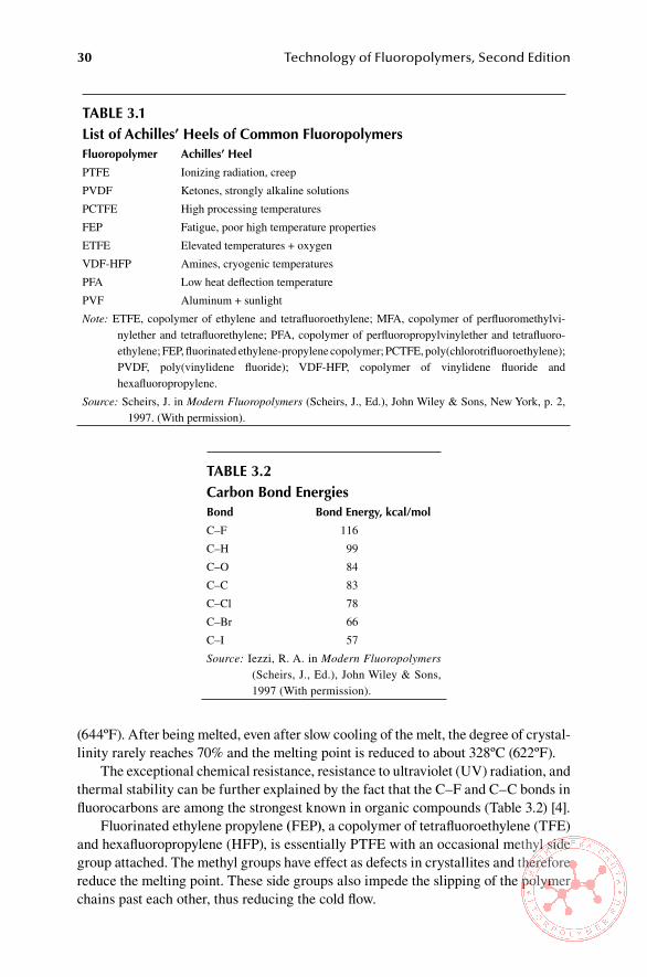
30 Technology of Fluoropolymers, Second Edition
(644ºF). After being melted, even after slow cooling of the melt, the degree of crystal-linity rarely reaches 70% and the melting point is reduced to about 328ºC (622ºF).
The exceptional chemical resistance, resistance to ultraviolet (UV) radiation, and thermal stability can be further explained by the fact that the C–F and C–C bonds in fluorocarbons are among the strongest known in organic compounds (Table 3.2) [4].
Fluorinated ethylene propylene (FEP), a copolymer of tetrafluoroethylene (TFE) and hexafluoropropylene (HFP), is essentially PTFE with an occasional methyl side group attached. The methyl groups have effect as defects in crystallites and therefore reduce the melting point. These side groups also impede the slipping of the polymer chains past each other, thus reducing the cold flow.
Table 3.1list of achilles’ heels of Common FluoropolymersFluoropolymer achilles’ heel
PTFE Ionizing radiation, creep
PVDF Ketones, strongly alkaline solutions
PCTFE High processing temperatures
FEP Fatigue, poor high temperature properties
ETFE Elevated temperatures + oxygen
VDF-HFP Amines, cryogenic temperatures
PFA Low heat deflection temperature
PVF Aluminum + sunlight
Note: ETFE, copolymer of ethylene and tetrafluoroethylene; MFA, copolymer of perfluoromethylvi-nylether and tetrafluorethylene; PFA, copolymer of perfluoropropylvinylether and tetrafluoro-ethylene; FEP, fluorinated ethylene-propylene copolymer; PCTFE, poly(chlorotrifluoroethylene); PVDF, poly(vinylidene fluoride); VDF-HFP, copolymer of vinylidene fluoride and hexafluoropropylene.
Source: Scheirs, J. in Modern Fluoropolymers (Scheirs, J., Ed.), John Wiley & Sons, New York, p. 2, 1997. (With permission).
Table 3.2Carbon bond energiesbond bond energy, kcal/mol
C–F 116
C–H 99
C–O 84
C–C 83
C–Cl 78
C–Br 66
C–I 57
Source: Iezzi, R. A. in Modern Fluoropolymers (Scheirs, J., Ed.), John Wiley & Sons, 1997 (With permission).
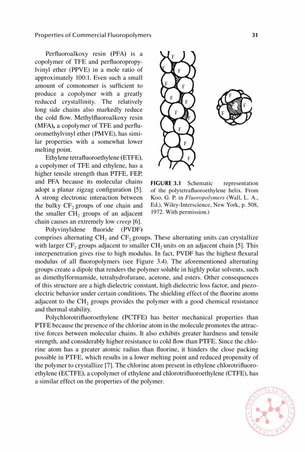
Properties of Commercial Fluoropolymers 31
Perfluoroalkoxy resin (PFA) is a copolymer of TFE and perfluoropropy-lvinyl ether (PPVE) in a mole ratio of approximately 100:1. Even such a small amount of comonomer is sufficient to produce a copolymer with a greatly reduced crystallinity. The relatively long side chains also markedly reduce the cold flow. Methylfluoroalkoxy resin (MFA), a copolymer of TFE and perflu-oromethylvinyl ether (PMVE), has simi-lar properties with a somewhat lower melting point.
Ethylene tetrafluoroethylene (ETFE), a copolymer of TFE and ethylene, has a higher tensile strength than PTFE, FEP, and PFA because its molecular chains adopt a planar zigzag configuration [5]. A strong electronic interaction between the bulky CF2 groups of one chain and the smaller CH2 groups of an adjacent chain causes an extremely low creep [6].
Polyvinylidene fluoride (PVDF) comprises alternating CH2 and CF2 groups. These alternating units can crystallize with larger CF2 groups adjacent to smaller CH2 units on an adjacent chain [5]. This interpenetration gives rise to high modulus. In fact, PVDF has the highest flexural modulus of all fluoropolymers (see Figure 3.4). The aforementioned alternating groups create a dipole that renders the polymer soluble in highly polar solvents, such as dimethylformamide, tetrahydrofurane, acetone, and esters. Other consequences of this structure are a high dielectric constant, high dielectric loss factor, and piezo-electric behavior under certain conditions. The shielding effect of the fluorine atoms adjacent to the CH2 groups provides the polymer with a good chemical resistance and thermal stability.
Polychlorotrifluoroethylene (PCTFE) has better mechanical properties than PTFE because the presence of the chlorine atom in the molecule promotes the attrac-tive forces between molecular chains. It also exhibits greater hardness and tensile strength, and considerably higher resistance to cold flow than PTFE. Since the chlo-rine atom has a greater atomic radius than fluorine, it hinders the close packing possible in PTFE, which results in a lower melting point and reduced propensity of the polymer to crystallize [7]. The chlorine atom present in ethylene chlorotrifluoro-ethylene (ECTFE), a copolymer of ethylene and chlorotrifluoroethylene (CTFE), has a similar effect on the properties of the polymer.
F
F F
F FF
FF
C
FF
FF
F
F
F
FiGURe 3.1 Schematic representation of the polytetrafluoroethylene helix. From Koo, G. P. in Fluoropolymers (Wall, L. A., Ed.), Wiley-Interscience, New York, p. 508, 1972. With permission.)
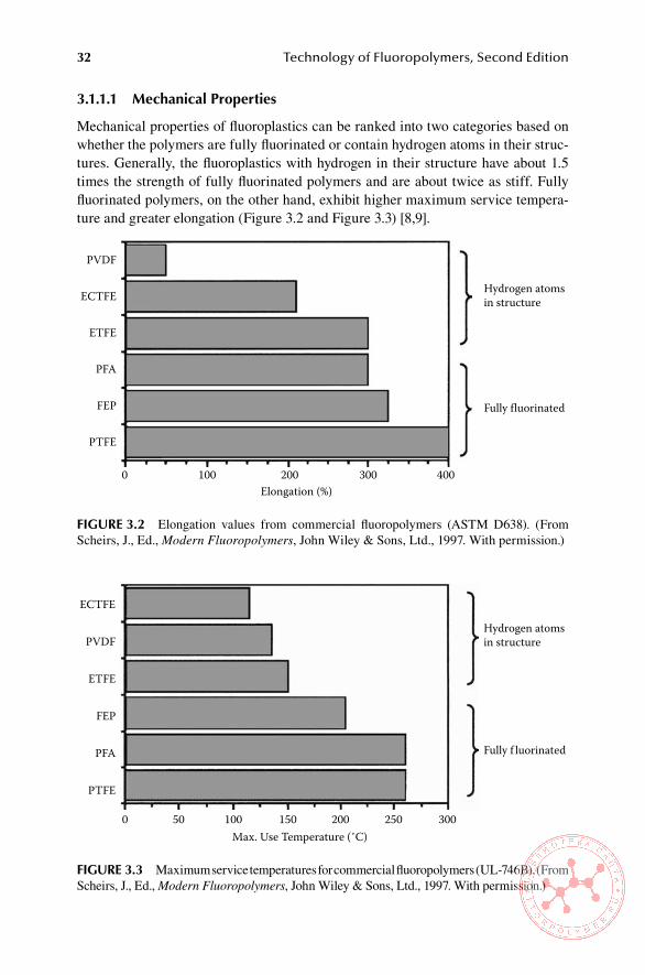
32 Technology of Fluoropolymers, Second Edition
3.1.1.1 Mechanical Properties
Mechanical properties of fluoroplastics can be ranked into two categories based on whether the polymers are fully fluorinated or contain hydrogen atoms in their struc-tures. Generally, the fluoroplastics with hydrogen in their structure have about 1.5 times the strength of fully fluorinated polymers and are about twice as stiff. Fully fluorinated polymers, on the other hand, exhibit higher maximum service tempera-ture and greater elongation (Figure 3.2 and Figure 3.3) [8,9].
PVDF
Hydrogen atomsin structure
Fully f luorinated
Elongation (%)
ECTFE
ETFE
PFA
FEP
PTFE
0 100 200 300 400
FiGURe 3.2 Elongation values from commercial fluoropolymers (ASTM D638). (From Scheirs, J., Ed., Modern Fluoropolymers, John Wiley & Sons, Ltd., 1997. With permission.)
ECTFE
Hydrogen atomsin structure
Fully f luorinated
Max. Use Temperature (˚C)
PVDF
ETFE
FEP
PFA
PTFE
0 10050 150 250200 300
FiGURe 3.3 Maximum service temperatures for commercial fluoropolymers (UL-746B). (From Scheirs, J., Ed., Modern Fluoropolymers, John Wiley & Sons, Ltd., 1997. With permission.)
1
1
1
1
1
' ' '
1
1
1
1
' '
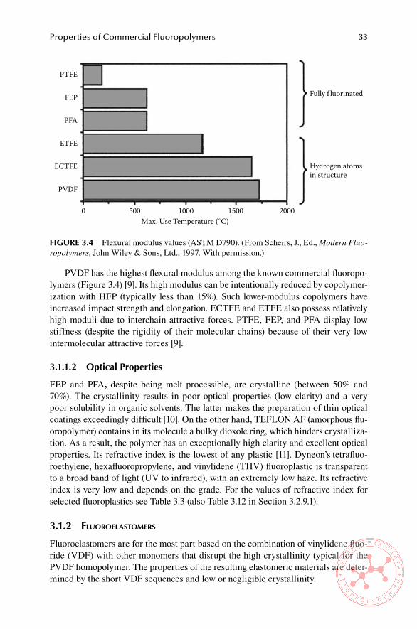
Properties of Commercial Fluoropolymers 33
PVDF has the highest flexural modulus among the known commercial fluoropo-lymers (Figure 3.4) [9]. Its high modulus can be intentionally reduced by copolymer-ization with HFP (typically less than 15%). Such lower-modulus copolymers have increased impact strength and elongation. ECTFE and ETFE also possess relatively high moduli due to interchain attractive forces. PTFE, FEP, and PFA display low stiffness (despite the rigidity of their molecular chains) because of their very low intermolecular attractive forces [9].
3.1.1.2 optical Properties
FEP and PFA, despite being melt processible, are crystalline (between 50% and 70%). The crystallinity results in poor optical properties (low clarity) and a very poor solubility in organic solvents. The latter makes the preparation of thin optical coatings exceedingly difficult [10]. On the other hand, TEFLON AF (amorphous flu-oropolymer) contains in its molecule a bulky dioxole ring, which hinders crystalliza-tion. As a result, the polymer has an exceptionally high clarity and excellent optical properties. Its refractive index is the lowest of any plastic [11]. Dyneon’s tetrafluo-roethylene, hexafluoropropylene, and vinylidene (THV) fluoroplastic is transparent to a broad band of light (UV to infrared), with an extremely low haze. Its refractive index is very low and depends on the grade. For the values of refractive index for selected fluoroplastics see Table 3.3 (also Table 3.12 in Section 3.2.9.1).
3.1.2 fluoroelastomers
Fluoroelastomers are for the most part based on the combination of vinylidene fluo-ride (VDF) with other monomers that disrupt the high crystallinity typical for the PVDF homopolymer. The properties of the resulting elastomeric materials are deter-mined by the short VDF sequences and low or negligible crystallinity.
PTFE
Fully f luorinated
Hydrogen atomsin structure
Max. Use Temperature (˚C)
FEP
PFA
ETFE
ECTFE
PVDF
0 500 1000 1500 2000
FiGURe 3.4 Flexural modulus values (ASTM D790). (From Scheirs, J., Ed., Modern Fluo-ropolymers, John Wiley & Sons, Ltd., 1997. With permission.)
_J
1
1 1 . .
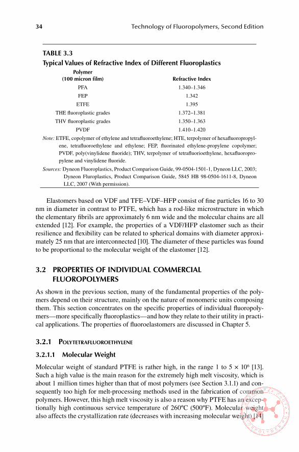
34 Technology of Fluoropolymers, Second Edition
Elastomers based on VDF and TFE–VDF–HFP consist of fine particles 16 to 30 nm in diameter in contrast to PTFE, which has a rod-like microstructure in which the elementary fibrils are approximately 6 nm wide and the molecular chains are all extended [12]. For example, the properties of a VDF/HFP elastomer such as their resilience and flexibility can be related to spherical domains with diameter approxi-mately 25 nm that are interconnected [10]. The diameter of these particles was found to be proportional to the molecular weight of the elastomer [12].
3.2 PRoPeRTies oF inDiviDUal CoMMeRCial FlUoRoPolYMeRs
As shown in the previous section, many of the fundamental properties of the poly-mers depend on their structure, mainly on the nature of monomeric units composing them. This section concentrates on the specific properties of individual fluoropoly-mers—more specifically fluoroplastics—and how they relate to their utility in practi-cal applications. The properties of fluoroelastomers are discussed in Chapter 5.
3.2.1 Polytetrafluoroethylene
3.2.1.1 Molecular Weight
Molecular weight of standard PTFE is rather high, in the range 1 to 5 × 10⁶ [13]. Such a high value is the main reason for the extremely high melt viscosity, which is about 1 million times higher than that of most polymers (see Section 3.1.1) and con-sequently too high for melt-processing methods used in the fabrication of common polymers. However, this high melt viscosity is also a reason why PTFE has an excep-tionally high continuous service temperature of 260ºC (500ºF). Molecular weight also affects the crystallization rate (decreases with increasing molecular weight) [14]
Table 3.3Typical values of Refractive index of Different Fluoroplastics
Polymer(100 micron film) Refractive index
PFA 1.340–1.346
FEP 1.342
ETFE 1.395
THE fluoroplastic grades 1.372–1.381
THV fluoroplastic grades 1.350–1.363
PVDF 1.410–1.420
Note: ETFE, copolymer of ethylene and tetrafluoroethylene; HTE, terpolymer of hexafluoropropyl-ene, tetrafluoroethylene and ethylene; FEP, fluorinated ethylene-propylene copolymer; PVDF, poly(vinylidene fluoride); THV, terpolymer of tetrafluorioethylene, hexafluoropro-pylene and vinylidene fluoride.
Sources: Dyneon Fluoroplastics, Product Comparison Guide, 99-0504-1501-1, Dyneon LLC, 2003; Dyneon Fluroplastics, Product Comparison Guide, 5845 HB 98-0504-1611-8, Dyneon LLC, 2007 (With permission).

Properties of Commercial Fluoropolymers 35
and specific gravity. So-called standard specific gravity (SSG) is calculated from the number minus average molecular weight (Mn) using the following mathematical expression [15]:
SSG = 2.612 – 0.058 log10 Mn
3.2.1.2 Molecular Conformation
The molecules of PTFE are very long and unbranched. Consequently, the virgin polymer, (i.e., the powder produced by polymerization) is highly crystalline with values of degree of crystallinity of 92% to 98% [16]. The CF2 groups are along the polymer chain, and the whole chain twists into a helix as in a length of a rope; the fluorine atoms are simply too large to allow a planar zigzag conformation, so the carbon chain twists to accommodate them [17], as pointed out in Section 3.1.1.
3.2.1.3 Crystallinity and Melting behavior
The initial high degree of crystallinity, reported to be well over 90%, can never be completely recovered after melting (i.e., sintering), presumably because of entangle-ments and other impediments caused by the extremely high molecular weight [18]. However, it has been established that rapidly cooled PTFE, although lower in the degree of crystallinity, has the same molecular conformation and basic crystalline structure as slowly cooled PTFE [19].
As pointed out earlier, the fluorine atoms are too large to allow planar zigzag structure, which confers rigidity on the polymer [20]. The PTFE molecule has a regular folded structure, which produces a laminar crystal [16].
The true densities of crystalline and amorphous PTFE differ considerably, and 100% crystalline PTFE densities of 2.347 at 0°C (32°F) and 2.302 at 25°C (77°F) were calculated from x-ray crystallographic data [21]. The density decrease of about 2% between these temperatures includes the decrease of approximately 1% due to the transition at 19°C (66°F), which results from a slight uncoiling of the helical con-formation of molecules on heating through the transition. By contrast, the density of amorphous PTFE is not affected by the transition at 19ºC, and values around 2.00 have been reported from extrapolations of specific volume measurements to zero crystallinity [15].
The density of PTFE undergoes complicated changes during processing and can be monitored by the values of true specific volume. Discontinuity in such data show the transitions at 19°C and 30°C (66°F and 86°F) and also the very pronounced tran-sition at the crystalline melting point of 327ºC (621ºF), the latter of which is due to the destruction of crystallinity [22]. The melting of the polymer is accompanied by a volume increase of approximately 30% [23]. The coefficient of linear expansion of PTFE has been determined at temperatures ranging from –190°C (–310°F) to +300°C (+572ºF) [24].
Effects of structural changes on properties, such as specific heat, specific vol-ume, or dynamic mechanical and electrical properties, are observed at various tem-
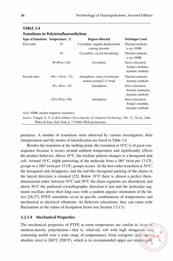
36 Technology of Fluoropolymers, Second Edition
peratures. A number of transitions were observed by various investigators; their interpretation and the modes of identification are listed in Table 3.4.
Besides the transition at the melting point, the transition at 19°C is of great con-sequence because it occurs around ambient temperature and significantly affects the product behavior. Above 19°C, the triclinic pattern changes to a hexagonal unit cell. Around 19°C, slight untwisting of the molecule from a 180° twist per 13 CF2 groups to a 180° twist per 15 CF2 groups occurs. At the first-order transition at 30°C, the hexagonal unit disappears, and the rod-like hexagonal packing of the chains in the lateral direction is retained [25]. Below 19°C there is almost a perfect three-dimensional order; between 19°C and 30°C the chain segments are disordered; and above 30°C the preferred crystallographic direction is lost and the molecular seg-ments oscillate above their long axes with a random angular orientation of the lat-tice [26,27]. PTFE transitions occur at specific combinations of temperatures and mechanical or electrical vibrations. As dielectric relaxations, they can cause wide fluctuations in the values of dissipation factor (see Section 3.2.1.7).
3.2.1.4 Mechanical Properties
The mechanical properties of PTFE at room temperature are similar to those of medium-density polyethylene—that is, relatively soft with high elongation and remaining useful over a wide range of temperatures, from cryogenic (just above absolute zero) to 260°C (500°F), which is its recommended upper use temperature
Table 3.4Transitions in PolytetrafluoroethyleneType of Transition Temperature, °C Region affected Technique Used
First order 19 Crystalline, angular displacement causing disorder
Thermal methods, x-ray, NMR
30 Crystalline, crystal disordering Thermal methods, x-ray, NMR
90 (80 to 110) Crystalline Stress relaxation, Young’s modulus, dynamic methods
Second order –90 (–110 to –73) Amorphous, onset of rotational motion around C–C bond
Thermal methods, dynamic methods
–30 (–40 to –15) Amorphous Stress relaxation, thermal expansion, dynamic methods
130 (120 to 140) Amorphous Stress relaxation, Young’s modulus, dynamic methods
Note: NMR, nuclear magnetic resonance.
Source: Gangal, S. V. in Kirk-Othmer Encyclopedia of Chemical Technology, Vol. 11, 3d ed., John Wiley & Sons, New York, p. 7 (1980) (With permission).
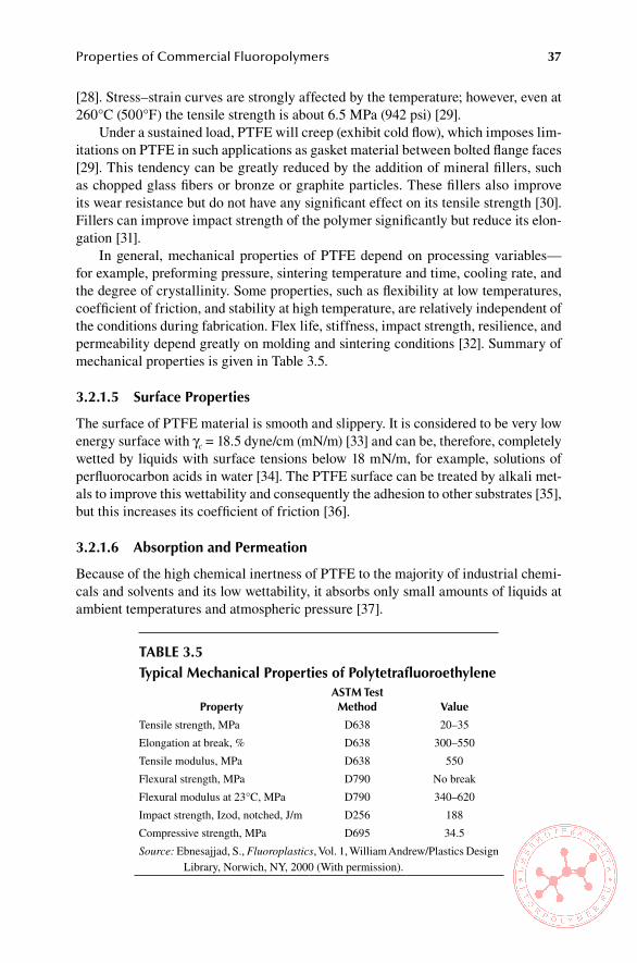
Properties of Commercial Fluoropolymers 37
[28]. Stress–strain curves are strongly affected by the temperature; however, even at 260°C (500°F) the tensile strength is about 6.5 MPa (942 psi) [29].
Under a sustained load, PTFE will creep (exhibit cold flow), which imposes lim-itations on PTFE in such applications as gasket material between bolted flange faces [29]. This tendency can be greatly reduced by the addition of mineral fillers, such as chopped glass fibers or bronze or graphite particles. These fillers also improve its wear resistance but do not have any significant effect on its tensile strength [30]. Fillers can improve impact strength of the polymer significantly but reduce its elon-gation [31].
In general, mechanical properties of PTFE depend on processing variables—for example, preforming pressure, sintering temperature and time, cooling rate, and the degree of crystallinity. Some properties, such as flexibility at low temperatures, coefficient of friction, and stability at high temperature, are relatively independent of the conditions during fabrication. Flex life, stiffness, impact strength, resilience, and permeability depend greatly on molding and sintering conditions [32]. Summary of mechanical properties is given in Table 3.5.
3.2.1.5 surface Properties
The surface of PTFE material is smooth and slippery. It is considered to be very low energy surface with γc = 18.5 dyne/cm (mN/m) [33] and can be, therefore, completely wetted by liquids with surface tensions below 18 mN/m, for example, solutions of perfluorocarbon acids in water [34]. The PTFE surface can be treated by alkali met-als to improve this wettability and consequently the adhesion to other substrates [35], but this increases its coefficient of friction [36].
3.2.1.6 absorption and Permeation
Because of the high chemical inertness of PTFE to the majority of industrial chemi-cals and solvents and its low wettability, it absorbs only small amounts of liquids at ambient temperatures and atmospheric pressure [37].
Table 3.5Typical Mechanical Properties of Polytetrafluoroethylene
PropertyasTM Test Method value
Tensile strength, MPa D638 20–35
Elongation at break, % D638 300–550
Tensile modulus, MPa D638 550
Flexural strength, MPa D790 No break
Flexural modulus at 23°C, MPa D790 340–620
Impact strength, Izod, notched, J/m D256 188
Compressive strength, MPa D695 34.5
Source: Ebnesajjad, S., Fluoroplastics, Vol. 1, William Andrew/Plastics Design Library, Norwich, NY, 2000 (With permission).

38 Technology of Fluoropolymers, Second Edition
Gases and vapors diffuse through PTFE much more slowly than through most other polymers. The higher the degree of crystallinity, the lower the rate of permeation. Voids greater than molecular size increase the permeability. Thus, it can be controlled by molding PTFE articles to low porosity and high density. Optimum density for that is 2.16 to 2.195 [37]. Permeability increases with temperature due to an increase in activity of the solvent molecules and the increase in vapor pressure of the liquids. Swelling of PTFE resin and films in any liquid is very low.
3.2.1.7 electrical Properties
The dielectric constant of polytetrafluoroethylene is 2.1 and remains constant within the temperature range from –40°C to 250°C (–40°F to 482°F) within the frequency range from 5 Hz to 10 GHz. It changes somewhat, however, with density and factors that affect density. The dielectric constant was found not to change over 2 to 3 years of measurements [38].
The dissipation factor is affected by the frequency, temperature, crystallinity, and void content of the fabricated structure. At certain temperatures the crystalline and amorphous regions become resonant. Because of the molecular vibrations, the applied electrical energy is lost by internal friction within the polymer, and this leads to an increase in dissipation factor. The dissipation factor peaks for these resins cor-respond to well-defined transitions [38].
The volume resistivity of polytetrafluoroethylene remains unchanged even after a prolonged soaking in water, because it does not absorb water. The surface arc-resistance of PTFE resins is high and is not affected by heat aging. They do not track or form a carbonized path when subjected to a surface arc in air [39]. The electrical properties of PTFE are summarized in Table 3.6.
3.2.2 coPolymers of tetrafluoroethylene and hexafluoroProPylene (hfP)
The copolymerization of TFE with HFP introduces a branched structure and results in the reduction of the melting point from the original 325°C (617°F) to about 260°C (500°F). Another consequence of that is a significant reduction of crystallinity,
Table 3.6Typical electrical Properties of Polytetrafluoroethylene
PropertyasTM Test Method value
Dielectric strength, short time, 0.08 in. V/mil D149 > 600
Surface arc resistance, s D495 > 300
Volume resistivity, ohm-cm D257 > 1018
Surface resistivity, ohm/sq D257 > 1016
Dielectric constant, at 60 to 2×10⁹ Hz D150 2.1
Dissipation factor, at 60 to 2×10⁹ Hz D150 0.0003
Source: Mechanical Design Bulletin (duPont) (With permission). Copyright © 1979–2005, E.I. du Pont de Nemours & Co. All rights reserved.

Properties of Commercial Fluoropolymers 39
which may vary between 70% for virgin polymer and 30% to 50% for molded parts [40] depending on processing conditions, mainly the cooling rate after melting. The melting point is the only first-order transition observed in FEP. Melting increases the volume by 8% [41].
3.2.2.1 Mechanical Properties
Mechanical properties of FEP are in general similar to those of PTFE with the exception of the continuous service temperature, 204°C (400°F) compared with that of PTFE (260°C, or 500°F). Unlike PTFE, FEP does not exhibit a marked volume change at room temperature because it is lacking the first-order transition at 19°C. FEP resins are useful above –267°C (–449°F) and are highly flexible above –79°C (–110°F) [42].
The static friction decreases with increasing load, and the static coefficient of friction is lower than the dynamic coefficient [43]. The coefficients of friction are independent of fabrication conditions.
Perfluorinated ethylene propylene tends to creep, and this has to be considered when designing parts for service under continuous stress. Creep can be reduced sig-nificantly by the use of suitable fillers, such as glass fibers or graphite. Graphite, bronze, and glass fibers also improve wear resistance and stiffness of the resin. The choice of fillers improving properties of FEP and their amounts are limited, how-ever, because of processing difficulties of such mixtures [44].
FEP resins have a very low energy surface and are, therefore, very difficult to wet. Surface preparation for improved wetting and bonding of FEP can be done by a solution of sodium in liquid ammonia or naphthalenylsodium in tetrahydrofurane [44] by the exposure to corona discharge [45] or to amines at elevated temperatures in an oxidizing atmosphere [46].
FEP resins exhibit very good vibration damping at sonic and ultrasonic frequen-cies. However, to use this property for welding of parts, the thickness of the resin must be sufficient to absorb the energy produced [44].
3.2.2.2 electrical Properties
Perfluorinated ethylene propylene has outstanding electrical properties, practically identical to those of PTFE within its recommended service temperature. Its volume resistivity remains unchanged even after prolonged soaking in water.
The dielectric constant of FEP is constant at lower frequencies, but at frequen-cies 100 MHz and higher it drops slightly with increasing frequency. Its dissipation factor has several peaks as a function of temperature and frequency. The magnitude of the dissipation peak is greater for FEP than for PTFE because the FEP structure is less symmetrical. The dielectric strength is high and unaffected by heat aging at 200°C (392°F) [47]. Electrical properties of FEP are listed in Table 3.7.
3.2.2.3 Chemical Properties
FEP resists most chemicals and solvents, even at elevated temperatures and pres-sures. Acid and bases are not absorbed at 200°C (392°F) and exposures of 1 year.

40 Technology of Fluoropolymers, Second Edition
Organic solvents are absorbed only a little, typically 1% or less, even at elevated tem-peratures and long exposure times. The absorption does not affect the resin and its properties and is completely reversible. The only chemicals reacting with FEP resins are fluorine, molten alkali metal, and molten sodium hydroxide [48].
Gases and vapors permeate FEP at a rate that is lower than for most plastics. It occurs only by molecular diffusion, because the polymer was melt processed. Because of the low permeability and chemical inertness, FEP is widely used in the chemical industry. Its permeation characteristics are similar to those of PTFE, with some advantage because of the absence of microporosity often present in PTFE. For the permeation through FEP films, an inverse relationship between permeability and film thickness applies [49].
3.2.2.4 optical Properties
FEP films transmit more UV, visible, and infrared radiation than ordinary win-dow glass. They are considerably more transparent to the infrared and UV spectra than glass. The refractive index of FEP films is in the range 1.341 to 1.347 [50] (Table 3.3).
3.2.2.5 other Properties
Products made from FEP resins resist the effects of weather, extreme heat, and UV radiation. This subject is covered in more detail in Chapter 7.
Table 3.7Typical values of electrical Properties of Fluorinated ethylene PropyleneProperty value asTM Method
Dielectric strength, kV/mm D149
0.254 mm 79
3.18 mm 20–21
Arc resistance, s 165 D495
Volume resistivity, ohm-cm 1017 D257
Dielectric constant, 21°C 2.01–2.05 2.02–2.04
D1531
1 kHz–500 MHz
13 GHz
Dissipation factor, 21°C D1531
1 kHz 0.00006
100 kHz 0.0003
1 MHz 0.0006
1 GHz 0.0011
13 GHz 0.0007
Surface resistivity, ohm/sq > 1018 D257
Source: Teflon FEP Fluoropolymer Resin, Product and Properties Handbook, 220338 (9/94) DuPont (September 1994) (With permission). Copyright © 1979–2005. E.I. du Pont de Nemours & Co. All rights reserved.

Properties of Commercial Fluoropolymers 41
3.2.3 coPolymers of tetrafluoroethylene and Perfluoroalkyl ethers (Pfa and mfa)
Because of the high bond strength among carbon, fluorine, and oxygen atoms, PFA and MFA exhibit nearly the same unique properties as PTFE at temperatures ranging from extremely low to extremely high. Since they can be relatively easily processed by conventional methods for thermoplastics into film and sheets without microporos-ity, they have distinct advantage over PTFE in certain applications, such as corro-sion protection and antistick coatings [51]. These polymers are semicrystalline, and the degree of crystallinity depends on the fabrication conditions, particularly on the cooling rate. General properties of PFA and MFA are listed and compared with FEP in Table 3.8.
3.2.3.1 Physical and Mechanical Properties
Commercial grades of PFA melt typically in the temperature range from 300°C to 315°C (572°F to 599°F) depending on the content of PPVE. The degree of crystal-linity is typically 60% [52].
There is only one first-order transition, at –5°C (23°F), and there are two second-order transitions, one at 85°C (185°F) and one at –90°C (–130°F) [52].
In general, mechanical properties of PFA are very similar to those of PTFE within the range from –200°C to +250°C (–328°F to +482°F). The mechanical prop-erties of PFA and MFA at room temperature are practically identical; differences become obvious only at elevated temperatures, because of the lower melting point of MFA.
Table 3.8General Properties of Perfluorinated Melt-Processable Polymers
General PropertiesasTM
Method Unit PFa MFa FeP
Specific gravity D792 g/cm3 2.12–2.17 2.12–2.17 2.12–2.17
Melting temperature D2116 oC 300–310 280–290 260–270
Coefficient of linear thermal expansion E831 1/K 10-5 12–20 12–20 12–20
Specific heat — kJ/kg K 1.0 1.1 1.2
Thermal conductivity D696 W/K.m 0.19 0.19 0.19
Flammability (UL 94) V–O V–O V–O
Oxygen index D2863 % > 95 > 95 > 95
Hardness Shore D D2240 55–60 55–60 55–60
Friction coefficient (on steel)
— — 0.2 0.2 0.3
Water absorption D570 % < 0.03 < 0.03 < 0.01
Note: PFA, copolymer of perfluoropropylvinylether and tetrafluoroethylene; MFA, copolymer of perfluoromethylvinylether and tetrafluorethylene; FEP, fluorinated ethylene-propylene copo-lymer; PVDF, poly(vinylidene fluoride). .
Source: Gangal, S. V. in Encyclopedia of Polymer Science and Technology, Vol. 16 (Mark, H. F. and Kroschwitz, J. I., Eds.), John Wiley & Sons, New York, p. 609 (1989) (With permission).
42 Technology of Fluoropolymers, Second Edition
In contrast to PTFE with measurable void content, the melt-processed PFA is intrinsically void free. As a result, lower permeation coefficients should result because permeation occurs by molecular diffusion. This is indeed the case, but the effect levels off at higher temperatures [53].
The most remarkable difference between PTFE and PFA is the considerably lower resistance to deformation under load (cold flow) of the latter. In fact, addition of even minute amounts of PFA to PTFE improves its resistance to cold flow [52] (see also Section 7.7).
3.2.3.2 electrical Properties
PFA and MFA exhibit considerably better electrical properties than most traditional plastics. In comparison with the partially fluorinated polymers, they are only slightly affected by temperature up to their maximum service temperature [54].
The dielectric constant remains at 2.04 over a wide range of temperature and frequencies (from 100 Hz to 1 GHz). The dissipation factor at low frequencies (from 10 Hz to 10 kHz) decreases with increasing frequency and decreasing temperature. In the range from 10 kHz to 1 MHz, temperature and frequency have little effect, whereas above 1 MHz the dissipation factor increases with the frequency [55].
3.2.3.3 optical Properties
Generally, fluorocarbon films exhibit high transmittance in the UV, visible, and infrared regions of the spectrum. This property depends on the degree of crystal-linity and the crystal morphology in the polymer. For example, 0.025 mm (0.001 in.) thick PFA film transmits more than 90% of visible light (wavelength 400 to 700 nm). A 0.2 mm (0.008 in.) thick MFA film was found to have a high transmittance in the UV region (wavelength 200 to 400 nm). The refractive indexes of these films are close to 1.3 [56].
3.2.3.4 Chemical Properties
PFA and MFA have an outstanding chemical resistance even at elevated tempera-tures. They are resistant to strong mineral acids, inorganic bases, and inorganic oxi-dizing agents and to most of the organic compounds and their mixtures common in the chemical industry. However, they react with fluorine and molten alkali [55].
Elemental sodium, as well as other alkali metals, reacts with perfluorocarbon polymers by removing fluorine from them. This reaction has a practical application for improving surface wettability and adhesive bonding of perfluorocarbon polymers to other substrates [57].
The absorption of water and solvents by perfluoropolymers is in general very low [57]. Permeability is closely related to absorption and depends on temperature, pressure, and the degree of crystallinity. Since these resins are melt processed, they are usually free of voids and, therefore, exhibit much lower permeability than PTFE. Permeation through PFA occurs via molecular diffusion [58].
Properties of Commercial Fluoropolymers 43
3.2.4 coPolymers of ethylene and tetrafluoroethylene (etfe)
Copolymers of ethylene and tetrafluoroethylene essentially comprise alternating eth-ylene and TFE units. They have an excellent balance of physical, chemical, mechani-cal, and electrical properties and are easily fabricated by melt-processing techniques but have found little commercial utility because they exhibit a poor resistance to cracking at elevated temperatures [59]. Incorporation of certain termonomers, so-called modifiers, in amounts 1 to 10 mol% markedly improves the cracking resis-tance, while maintaining the desirable properties of the copolymer [60,61]. ETFE resins are manufactured by several companies under different trade names.
3.2.4.1 structure and Related Properties
The carbon chain is in a planar zigzag orientation and forms an orthorhombic lattice with interpenetration of adjacent chains [61]. As a result of this structure, ETFE has an exceptionally low creep, high tensile strength, and high modulus compared with other thermoplastic fluoropolymers. Interchain forces hold this matrix until the alpha transition occurs at about 110ºC (230ºF), where the physical properties of ETFE begin to decline and more closely resemble perfluoropolymer properties at the same temperature. Other transitions occur at –120ºC (–184ºF) (gamma) and about –25ºC (–13ºF) (beta) [62].
The monomer ratio in the copolymer has an effect on the polymer structure and properties, mainly on the degree of crystallinity and on the melting point. As nor-mally produced, ETFE has about 88% of alternating sequences and a melting point of 270ºC (518ºF) [63].
3.2.4.2 Mechanical, Chemical, and other Properties
ETFE exhibits exceptional toughness and abrasion resistance over a wide tempera-ture range and a good combination of high tensile strength, high impact strength, flex and creep resistance, and combining mechanical properties of hydrocarbon engi-neering polymers with the chemical and thermal resistance of perfluoropolymers. Friction and wear properties are good and can be improved by incorporating fill-ers such as fiberglass or bronze powders. Fillers also improve creep resistance and increase the softening temperature [61].
Continuous upper service temperature of commercial ETFE is 150ºC (302ºF) [64]. Physical strength can be maintained at even higher temperatures when the poly-mer is cross-linked by peroxide or ionizing radiation [65]. Highly cross-linked resins can be subjected to temperatures up to 240ºC (464ºF) for short periods of time [64].
ETFE exhibits excellent dielectric properties. Its dielectric constant is low and essentially independent of frequency. The dissipation factor is low but increases with frequency and can be also increased by cross-linking. Dielectric strength and resis-tivity are high and are unaffected by water. Irradiation and cross-linking increase dielectric loss [64].
Modified ETFE has excellent resistance to most common solvents and chemi-cals [66]. It is not hydrolyzed by boiling water, and weight gain is less than 0.03% in water at room temperature. Strong oxidizing acids, such as nitric acid, and some

44 Technology of Fluoropolymers, Second Edition
organic bases cause depolymerization at high concentrations and high temperatures [64]. ETFE is also an excellent barrier to hydrocarbons and oxygenated components of automotive fuels [64].
ETFE resins have a good thermal stability; however, for high-temperature appli-cations thermal stabilizers are often added [67]. A wide variety of compounds, mostly metal salts (e.g., copper oxides and halides, aluminum oxide, and calcium salts), will act as sacrificial sites for oxidation. Addition of certain salts can alter the decomposi-tion from oligomer formation to dehydrofluorination. Iron and other transition metal salts accelerate the dehydrofluorination. Hydrofluoric acid itself destabilizes ETFE at elevated temperatures, and the degradation becomes self-accelerating. For that reason, extrusion temperatures higher than 380ºC (716ºF) should be avoided [68].
Ionizing radiation at lower levels affects ETFE polymers very little; therefore, they are being used for wire coatings and molded parts in the nuclear energy indus-try [68]. More details are provided in Chapter 8.
ETFE resins do not support combustion in air and have typical limiting oxygen index (LOI) of about 30 to 31. LOI depends on monomer ratio in the polymer, and it increases gradually as the fluorocarbon content is increased to the alternating com-position and then increases more rapidly to the LOI values for PTFE [68]
ETFE resins are very often compounded with varied ingredients, such as glass fibers and bronze powder, to attain certain mechanical properties. For example, glass fibers are added at 25 to 35 wt% levels to increase modulus and to improve wear and friction characteristics. By adding 25% glass fibers, for example, the dynamic coef-ficient of friction is reduced from about 0.5 to about 0.3 [69].
3.2.5 PolyVInylIdene fluorIde (PVdf)
PVDF homopolymer is a semicrystalline polymer. Its degree of crystallinity can vary from 35% to more than 70%, depending on the method of preparation and ther-momechanical history [70]. The degree of crystallinity greatly affects the toughness and mechanical strength as well as the impact resistance of the polymer. Other major factors influencing the properties of PVDF are molecular weight, molecular weight distribution, and extent of irregularities along the polymer chain and the crystalline form. Similar to other linear polyolefins, crystalline forms of polyvinylidene fluoride involve lamellar and spherulitic forms. The differences in the size and distribution of the domains as well as the kinetics of crystal growth are related to the method of polymerization [70].
PVDF exhibits a complex crystalline polymorphism, which cannot be found in other known synthetic polymers. There are a total of four distinct crystalline forms: alpha, beta, gamma, and delta. These are present in different proportions in the material, depending on a variety of factors that affect the development of the crystalline structure, such as pressure, intensity of the electric field, controlled melt crystallization, precipitation from different solvents, or seeding crystallization (e.g., surfactants). The alpha and beta forms are most common in practical situations. Gen-erally, the alpha form is generated in normal melt processing; the beta form devel-ops under mechanical deformation of melt-fabricated specimens. The gamma form arises under special circumstances, and the delta form is obtained by distortion of
Properties of Commercial Fluoropolymers 45
one of the phases under high electrical fields [70]. The density of PVDF in the alpha crystal form is 1.98 g/cm3; the density of amorphous PVDF is 1.68 g/cm3. Thus, the typical density of commercial products in the range from 1.75 to 1.78 g/cm3 reflects a degree of crystallinity around 40%.
The structure of polyvinylidene fluoride chain, namely, alternating CH2 and CF2 groups, has an effect on its properties that combines some of the best perfor-mance characteristics of both polyethylene (–CH2–CH2–)n and polytetrafluoroeth-ylene (–CF2–CF2–)n. Certain commercial grades of PVDF are copolymers of VDF with small amounts (typically less than 6%) of other fluorinated monomers, such as HFP, CTFE, and TFE. These exhibit somewhat different properties than the homopolymer.
3.2.5.1 Mechanical Properties
PVDF exhibits excellent mechanical properties (Table 3.9), and when compared with perfluorinated polymers it has much higher resistance to elastic deformation under load (creep), much longer life in repeated flexing, and improved fatigue resistance [71,72]. Its mechanical strength can be greatly increased by orientation [70]. Some additives, such as glass spheres and carbon fibers [73], increase the strength of the base polymer.
3.2.5.2 electrical Properties
Typical values of electrical properties of the homopolymer without additives and treatments are listed in Table 3.10. The values can be substantially changed by the type of cooling and post-treatments, which determine the morphological state of the polymer. Dielectric constants as high as 17 have been measured on oriented samples that have been subjected to high electrical fields (poled) under various conditions to orient polar crystalline form [74].
The unique dielectric properties and polymorphism of PVDF are the source of its high piezoelectric and pyroelectric activity [75]. The relationship between fer-roelectric behavior, which includes piezoelectric and pyroelectric phenomena, and other electrical properties of the polymorphs of polyvinylidene fluoride is discussed in [76].
The structure yielding a high dielectric constant and a complex polymorphism also exhibits a high dielectric loss factor. This excludes PVDF from applications as an insulator for conductors of high frequency currents since the insulation could heat up and possibly even melt. On the other hand, because of that PVDF can be readily melted by radiofrequency or dielectric heating, and this can be utilized for certain fabrication processes or joining [77]. High-energy radiation cross-links poly-vinylidene fluoride, and the result is the enhancement of mechanical properties (see Chapter 8, Section 8.2.2). This feature makes it unique among vinylidene polymers, which typically are degraded by high-energy radiation [74].

46 Technology of Fluoropolymers, Second Edition
Table 3.9Typical Properties of Polyvinylidene FluorideProperties value or DescriptionClarity Transparent to translucentMelting point, crystalline, °C 155–192Specific gravity 1.75–1.80Refractive index n25
D 1.42Mold shrinkage, average, % 2–3Color possibilities UnlimitedMachining qualities ExcellentFlammability Self-extinguishing, nondrippingTensile strength, MPaa
At 25°C 42–58.5 At 100°C 34.5Elongation, % At 25°C 50–300 At 100°C 200–500Yield point, MPaa
At 25°C 38–52 At 100°C 17Creep, at 13.79 MPaa and 25°C for 10,000 h, % 2–4Compressive strength, at 25°C, MPaa 55–90Modulus of elasticity, at 25°C, GPab
In tension 1.0–2.3 In flexure 1.1–2.5 In compression 1.0–2.3Izod impact, at 25°C, J/mc
Notched 75–235 Unnotched 700–2300Durometer hardness, Shore D scale 77–80Heat-distortion temperature, °C At 0.455 MPaa 140–168 At 1.82 MPaa 80–128Abrasion resistance, Taber CS-17, 0.5 kg load, mg/1000 cycles 17.6
Coefficient of sliding friction to steel 0.14–0.17Thermal coefficient of linear expansion, per °C 0.7–1.5 × 10⁻⁴
Thermal conductivity, at 25°C–160°C, W/(m.K) 0.17–0.19Specific heat, (J/(kg.K)d 1255–1425Thermal degradation temperature, °C 390Low temperature embrittlement, °C –60Water absorption, % 0.04Moisture vapor permeability, for 1 mm thickness, g/(24 h)(m2)
2.5 × 10⁻²
Radiation resistance (60CO), MGye,f 10–12a To convert MPa to psi, multiply by 145.b To convert GPa to psi, multiply by 145,000.c To convert J/m to ftlbf/in., divide by 53.38.d To convert J to cal, divide by 4.184.e Retains tensile strength of about 85% of its original value.f To convert Gy to rad, multiply by 100.Source: Gangal, S. V. in Kirk-Othmer Encyclopedia of Chemical Technology, Vol. 11, 3d ed., John
Wiley & Sons, New York, p. 8 (1980) (With permission).

Properties of Commercial Fluoropolymers 47
3.2.5.3 Chemical Properties
Polyvinylidene fluoride exhibits an excellent resistance to most inorganic acids, weak bases, and halogens, oxidizing agents even at elevated temperatures, and to aliphatic, aromatic, and chlorinated solvents. Strong bases, amines, esters, and ketones cause its swelling, softening, and dissolution, depending on conditions [78]. Certain esters and ketones can act as latent solvents for PVDF in dispersions. Such systems solvate the polymer as the temperature is raised during the fusion of the coating, resulting in a cohesive film [79].
PVDF is among the few semicrystalline polymers that exhibit thermodynamic compatibility with other polymers [80], in particular with acrylic or methacrylic res-ins [81]. The morphology, properties, and performance of these blends depend on the structure and composition of the additive polymer, as well as on the particular PVDF resin. These aspects have been studied and are reported in some detail in [82]. For example, polyethyl acrylate is miscible with polyvinylidene fluoride, but poly-isopropyl acrylate and homologues are not. Strong dipolar interactions are important to achieve miscibility with PVDF, as suggested by the observation that polyvinyl fluoride is incompatible with polyvinylidene fluoride [83].
3.2.6 PolychlorotrIfluoroethylene (Pctfe)
The inclusion of the relatively large chlorine into the polymeric chain reduces the tendency to crystallize. Commercially available grades include a homopolymer, which is mainly used for special applications, and copolymers with small amounts (less than 5%) of vinylidene fluoride [84]. The products are supplied as powder, pel-lets, pellets containing 15% glass fiber, and dispersions. Low-molecular-weight poly-mer is available as oil or grease. The oil is used to plasticize PCTFE [85].
3.2.6.1 Thermal Properties
PCTFE is highly suitable for applications at extremely low temperatures; however, at elevated temperatures it is inferior to other fluoropolymers with the exception of PVDF. It has a relatively low melting point of 211°C (412°F), and it exhibits
Table 3.10Typical electrical Properties of Polyvinylidene Fluoride homopolymer
Property 60 hz 103 hz 106 hz 109 hz
Dielectric constant at 25°C 9–10 8–9 8–9 3–4
Dissipation factor 0.03–0.05 0.005–0.02 0.03–0.05 0.09–0.11
Volume resistivity, ohm.m 2 × 10¹²
Dielectric strength, short time, V/2.54 × 10-5 m
0.003175 m thickness 260
0.000203 m thickness 1300
Source: Gangal, S. V. in Kirk-Othmer Encyclopedia of Chemical Technology, Vol. 11, 3d ed., John Wiley & Sons, New York, p. 8 (1980) (With permission).
48 Technology of Fluoropolymers, Second Edition
thermally induced crystallization at temperatures below its melting point, which results in brittleness [84].
3.2.6.2 Mechanical, Chemical, and other Properties
As long as thermally induced crystallization (see previous secion) is avoided, PCTFE exhibits excellent mechanical properties. It also has an excellent resistance to creep [83]. The addition of glass fibers (typically 15%) improves high-temperature proper-ties and increases hardness but also increases brittleness [86].
PCTFE has an excellent chemical resistance, especially the resistance to most very harsh environments, particularly to strong oxidizing agents (e.g., fuming oxi-dizing acids, liquid oxygen, ozone) and to sunlight. PCTFE alone has a good resis-tance to ionizing radiation that is further improved by copolymerization with small amounts of VDF (see previous section) [86]. The homopolymers and copolymers with VDF exhibit outstanding barrier properties [87]. PCTFE does not absorb visible light, and it is possible to produce optically clear sheets and parts up to 3.2 mm (1/8 in.) thick by quenching from melt [86,87].
The disadvantage of PCTFE is that it is attacked by many organic materials and has a low thermal stability in the molten state. The latter requires great care during processing to maintain high enough molecular weight necessary for good mechani-cal properties of the fabricated parts [86].
3.2.7 coPolymer of ethylene and chlorotrIfluoroethylene (ectfe)
Commercial polymer with an overall CTFE-to-ethylene ratio of 1:1 contains ethyl-ene blocks and CTFE blocks of less than 10 mol% each. The modified copolymers also produced commercially exhibit improved high-temperature stress cracking. Typically, the modified copolymers are less crystalline and have lower melting points [88]. Modifying monomers are hexafluoroisobutylene (HFIB), perfluorohexylethyl-ene, and perfluoropropylvinyl ether (PPVE) [89].
3.2.7.1 Properties of eCTFe
ECTFE resins are tough, moderately stiff, and creep resistant with service tempera-tures from –100°C to +150°C (–148°F to +302°F). The melt temperature depends on the monomer ratio in the polymer and is in the range of 235°C to 245°C (455°F to 473°F). Its chemical resistance is good and similar to PCTFE. ECTFE, as most fluoropolymers, has an outstanding weathering resistance. It also resists high-energy gamma and beta radiation up to 100 Mrad (1000 kGy).
3.2.8 terPolymer of tetrafluoroethylene, hexafluoroProPylene, and VInylIdene (thV) fluorIde (thV fluoroPlastIc)
The driving force for the development of THV fluoroplastic was the requirement for a fluoropolymer that could be used as a coating for polyester fabrics and provide pro-tection similar to that of PTFE or ETFE in outdoor exposure. An additional require-
Properties of Commercial Fluoropolymers 49
ment was that it could be used with PVC-coated polyester fabric without significantly compromising overall flexibility [90].
Chemically, THV fluoroplastic is a terpolymer of TFE, HFP, and VDF pro-duced by emulsion polymerization. The resulting dispersion is either processed into powders and pellets or concentrated with emulsifier and supplied in that form to the market [91]. Currently, the manufacturer is Dyneon LLC, and there are essentially nine commercial grades (five dry grades in pellet or agglomerate form and four aqueous dispersions) available that differ in the monomer ratios and consequently in melting points, chemical resistance, optical properties, and flexibility.
3.2.8.1 Properties
THV has a unique combination of properties that include relatively low processing temperatures, bondability (to itself and other substrates), high flexibility, excellent clarity, low refractive index, and efficient electron-beam cross-linking [91]. It also exhibits properties associated with fluoroplastics, namely, very good chemical resis-tance, weatherability, low friction, and low flammability. Typical properties of the dry grades are summarized in Table 3.11.
The melting temperatures of the THV commercial products range from 120°C (248°F) for THV 200 to 225°C (435°F) for THV 815. The lowest melting grade has the lowest chemical resistance and is easily soluble in ketones and ethyl acetate, is the most flexible, and is the easiest to cross-link by electron beam of all grades. On the other hand, the highest melting grade has also the highest chemical resistance and resistance to permeation [91].
THV can be readily bonded to itself and to many plastics and elastomers and, unlike other fluoroplastics, does not require surface treatment, such as chemical etch-ing or corona treatment. However, in some cases tie layers are required to achieve a good bonding to other materials [92].
THV is transparent to a broad band of light (UV to infrared) with an extremely low haze. Its refractive index is very low and depends on the grade [93] (Table 3.12).
3.2.9 terPolymer of hexafluoroProPylene, tetrafluoroethylene, and ethylene (hte) fluoroPlastIc
HTE fluoroplastic exhibits exceptional balance of tensile strength, good electrical properties, good resistance to permeation of vapors and fuels, as well as excellent chemical resistance. Because of its relatively low melting temperature, it is easy to process and can be processed on equipment without the high level of corrosion pro-tection usually required by many other fluoroplastics. HTE is suitable for wire and cable insulation and for extruded films used for chemically resistant linings, release layers, and other applications. A summary of properties of the two current grades of HTE is shown in Table 3.13.
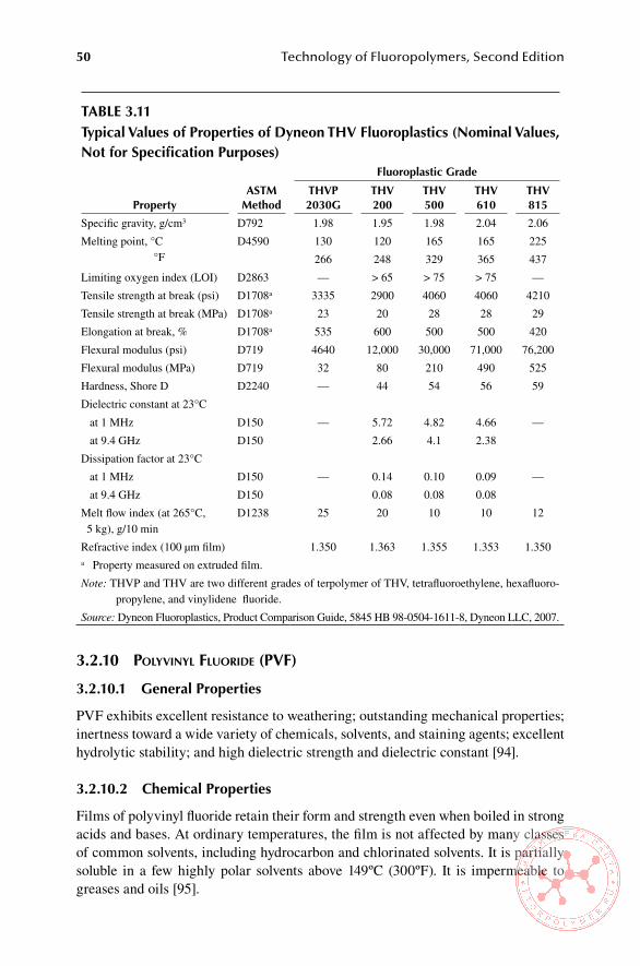
50 Technology of Fluoropolymers, Second Edition
3.2.10 PolyVInyl fluorIde (PVf)
3.2.10.1 General Properties
PVF exhibits excellent resistance to weathering; outstanding mechanical properties; inertness toward a wide variety of chemicals, solvents, and staining agents; excellent hydrolytic stability; and high dielectric strength and dielectric constant [94].
3.2.10.2 Chemical Properties
Films of polyvinyl fluoride retain their form and strength even when boiled in strong acids and bases. At ordinary temperatures, the film is not affected by many classes of common solvents, including hydrocarbon and chlorinated solvents. It is partially soluble in a few highly polar solvents above 149ºC (300ºF). It is impermeable to greases and oils [95].
Table 3.11Typical values of Properties of Dyneon Thv Fluoroplastics (nominal values, not for specification Purposes)
PropertyasTM
Method
Fluoroplastic Grade
ThvP 2030G
Thv 200
Thv 500
Thv 610
Thv 815
Specific gravity, g/cm3 D792 1.98 1.95 1.98 2.04 2.06
Melting point, °C °F
D4590 130 120 165 165 225
266 248 329 365 437
Limiting oxygen index (LOI) D2863 — > 65 > 75 > 75 —
Tensile strength at break (psi) D1708a 3335 2900 4060 4060 4210
Tensile strength at break (MPa) D1708a 23 20 28 28 29
Elongation at break, % D1708a 535 600 500 500 420
Flexural modulus (psi) D719 4640 12,000 30,000 71,000 76,200
Flexural modulus (MPa) D719 32 80 210 490 525
Hardness, Shore D D2240 — 44 54 56 59
Dielectric constant at 23°C
— — at 1 MHz D150 5.72 4.82 4.66
at 9.4 GHz D150 2.66 4.1 2.38
Dissipation factor at 23°C
— — at 1 MHz D150 0.14 0.10 0.09
at 9.4 GHz D150 0.08 0.08 0.08
Melt flow index (at 265°C, 5 kg), g/10 min
D1238 25 20 10 10 12
Refractive index (100 μm film) 1.350 1.363 1.355 1.353 1.350a Property measured on extruded film.
Note: THVP and THV are two different grades of terpolymer of THV, tetrafluoroethylene, hexafluoro-propylene, and vinylidene fluoride.
Source: Dyneon Fluoroplastics, Product Comparison Guide, 5845 HB 98-0504-1611-8, Dyneon LLC, 2007.
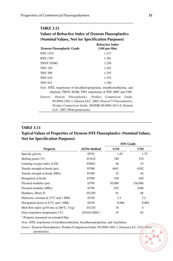
Properties of Commercial Fluoropolymers 51
Table 3.12values of Refractive index of Dyneon Fluoroplastics (nominal values, not for specification Purposes)
Dyneon Fluoroplastic GradeRefractive index(100 μm film)
HTE 1510 1.372
HTE 1705 1.381
THVP 2030G 1.350
THV 220 1.363
THV 500 1.355
THV 610 1.353
THV 815 1.350
Note: HTE, terpolymer of hexafluoropropylene, tetrafluoroethylene, and ethylene; THVP, 20306, THV, terpolymer of TFE, HFP, and VDF.
Sources: Dyneon Fluoroplastics, Product Comparison Guide, 99-0504-1501-1, Dyneon LLC, 2003; Dyneon™ Fluoroplastics, Product Comparison Guide, 5845HB 98-0504-1611-8, Dyneon LLC, 2007 (With permission).
Table 3.13Typical values of Properties of Dyneon hTe Fluoroplastics (nominal values, not for specification Purposes)
Property asTM Method
hTe Grade
1510 1705
Specific gravity D792 1.85 1.75
Melting point (°C) D3418 180 210
Limiting oxygen index (LOI) D2863 46 33
Tensile strength at break (psi) D708a 4641 6382
Tensile strength at break (MPa) D708a 32 44
Elongation at break D708a 520 420
Flexural modulus (psi) D790 95,000 150,000
Flexural modulus (MPa) D790 655 1040
Hardness, Shore D D2240 61 66
Dielectric constant at 23°C and 1 MHz D150 2.3 2.2
Dissipation factor at 23°C and 1 MHz D150 0.006 0.004
Melt flow index (g/10 min at 260°C, 5 kg) D1238 10 4
Glass transition temperature (°C) D3418 (DSC) 35 65a Property measured on extruded film.
Note: HTE, terpolymer of tetrafluoroethylene, hexafluoropropylene, and vinylidene.
Source: Dyneon Fluoroplastics, Product Comparison Guide, 99-0504-1501-1, Dyneon LLC, 2003 (With permission).
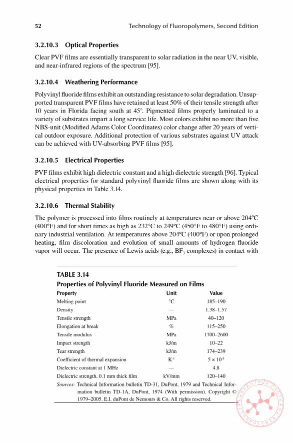
52 Technology of Fluoropolymers, Second Edition
3.2.10.3 optical Properties
Clear PVF films are essentially transparent to solar radiation in the near UV, visible, and near-infrared regions of the spectrum [95].
3.2.10.4 Weathering Performance
Polyvinyl fluoride films exhibit an outstanding resistance to solar degradation. Unsup-ported transparent PVF films have retained at least 50% of their tensile strength after 10 years in Florida facing south at 45°. Pigmented films properly laminated to a variety of substrates impart a long service life. Most colors exhibit no more than five NBS-unit (Modified Adams Color Coordinates) color change after 20 years of verti-cal outdoor exposure. Additional protection of various substrates against UV attack can be achieved with UV-absorbing PVF films [95].
3.2.10.5 electrical Properties
PVF films exhibit high dielectric constant and a high dielectric strength [96]. Typical electrical properties for standard polyvinyl fluoride films are shown along with its physical properties in Table 3.14.
3.2.10.6 Thermal stability
The polymer is processed into films routinely at temperatures near or above 204ºC (400ºF) and for short times as high as 232°C to 249ºC (450°F to 480°F) using ordi-nary industrial ventilation. At temperatures above 204ºC (400ºF) or upon prolonged heating, film discoloration and evolution of small amounts of hydrogen fluoride vapor will occur. The presence of Lewis acids (e.g., BF3 complexes) in contact with
Table 3.14Properties of Polyvinyl Fluoride Measured on FilmsProperty Unit value
Melting point °C 185–190
Density — 1.38–1.57
Tensile strength MPa 40–120
Elongation at break % 115–250
Tensile modulus MPa 1700–2600
Impact strength kJ/m 10–22
Tear strength kJ/m 174–239
Coefficient of thermal expansion K-1 5 × 10⁻⁵
Dielectric constant at 1 MHz — 4.8
Dielectric strength, 0.1 mm thick film kV/mm 120–140
Sources: Technical Information bulletin TD-31, DuPont, 1979 and Technical Infor-mation bulletin TD-1A, DuPont, 1974 (With permission). Copyright © 1979–2005. E.I. duPont de Nemours & Co. All rights reserved.
Properties of Commercial Fluoropolymers 53
PVF is known to catalyze the decomposition of the polymer at lower-than-normal temperature. A thorough study of degradation of polyvinyl fluoride films is reported in [97].
PVF films are available in large variety under the trade name TEDLAR PVF from DuPont Fluoropolymers. Type 1 film has controlled shrinkage for surfacing fiberglass-surfaced polyester panels and truck trailer bodies; Type 2 clear film exhib-its high tensile strength and high flex; Type 3, the standard film, is available in clear and pigmented forms. A clear film Type 4 has high elongation and high tear resis-tance. Type 5 TEDLAR film has been developed for applications where deep draw and texturing are required. Its ultimate elongation is almost twice that of standard Type 3 film. The thickness of commercially available PVF films ranges from 0.5 to 2.0 mil (12.5 to 50 μm).
TEDLAR films are supplied with different surface characteristics. “A” (one side adherable) and “B” (both sides adherable) surfaces are used with adhesives for bonding to a wide variety of substrates. These surfaces can be bonded with a vari-ety of adhesives, including acrylics, polyesters, epoxies, elastomeric adhesives, and pressure-sensitive mastics. The “S” surface has excellent antistick properties and is being used as a mold-release film for parts made from epoxies, phenolics, elasto-mers, and other polymeric materials [94].
ReFeRenCes
1. Scheirs, J., in Modern Fluoropolymers (Scheirs, J., Ed.), John Wiley & Sons, Ltd, Chichester, UK, p. 2 (1997).
2. Pozzoli, M., Vita, G., and Arcella, V., in Modern Fluoropolymers (Scheirs, J., Ed.), John Wiley & Sons, Ltd, Chichester, UK, p. 374 (1997).
3. Koo, G. P., in Fluoropolymers (Wall. L. A., Ed.), Wiley-Interscience, New York, p. 508 (1972)
4. Sheratt, S., in Kirk-Othmer Encyclopedia of Chemical Technology, Vol.9, John Wiley & Sons, New York, p. 826 (1966).
5. Scheirs, J., in Modern Fluoropolymers (Scheirs, J., Ed.), John Wiley & Sons, Ltd, Chichester, UK, p. 3 (1997).
6. Kerbow, D. L., in Modern Fluoropolymers (Scheirs, J., Ed.), John Wiley & Sons, Ltd, Chichester, UK, p. 307 (1997).
7. Saunders, K. J., Organic Polymer Chemistry, Chapman & Hall, London, 2nd ed., Chap-ter 7, p. 149 (1988).
8. Scheirs, J., in Modern Fluoropolymers (Scheirs, J., Ed.), John Wiley &Sons, Ltd, Chichester, UK, p. 5 (1997).
9. Scheirs, J., in Modern Fluoropolymers (Scheirs, J., Ed.), John Wiley & Sons, Ltd, Chichester, UK, p. 6 and p. 33 (1997).
10. Scheirs, J., in Modern Fluoropolymers (Scheirs, J., Ed.), John Wiley & Sons, Ltd, Chichester, UK, p. 7 (1997).
11. Resnick, P. R. and Buck, W. H., Teflon® AF Amorphous Fluoropolymers, in Modern Fluoropolymers (Scheirs, J., Ed.) John Wiley & Sons, Ltd, Chichester, UK, Chapter 22 (1997).
12. Yamaguchi, S. and Tatemoto, M., “Fine structure of fluorine elastomer emulsions”, in Sen’i Gakkaishi 50, p. 414 (1994).
13. Sheratt, S., in Kirk-Othmer Encyclopedia of Chemical Technology, Vol. 9, John Wiley & Sons, New York, p. 817 (1966).
54 Technology of Fluoropolymers, Second Edition
14. Gangal, S. V., in Kirk-Othmer Encyclopedia of Chemical Technology, Vol.11, 3rd ed., John Wiley & Sons, New York, p. 7 (1980).
15. Sperati, A. C. and Starkweather, H. W., Fortschr. Hochpolym. Forsch. 2, p. 465 (1961).
16. Gangal, S. V., in Kirk-Othmer Encyclopedia of Chemical Technology, Vol. 11, 3rd ed., John Wiley & Sons, New York, p. 8 (1980).
17. Bunn, C. W. and Howels, E. R., Nature 174, 549 (1954). 18. Sheratt, S., in Kirk-Othmer Encyclopedia of Chemical Technology, Vol. 9, John Wiley
& Sons, New York, p. 819 (1966). 19. Clark, E. S. and Starkweather, H. W., J. Appl. Polym. Sci. 6, S41 (1962). 20. Bunn, C. W., J. Polym. Sci. 16, p. 332 (1955). 21. Clark, E. S. and Muus, L. T., Z. Krystallogr. 117, p. 119 (1962). 22. Sheratt, S., in Kirk-Othmer Encyclopedia of Chemical Technology, Vol. 9, John Wiley
& Sons, New York, p. 820 (1966). 23. Gangal, S.V., in Kirk-Othmer Encyclopedia of Chemical Technology, Vol. 11, 3rd ed.,
John Wiley & Sons, New York, p. 8 (1980). 24. Kirby, R. K. Z., J. Res. Natl. Bur. Std. 57, 91 (1956). 25. Doban, R. C., Knight, A.C., Peterson, A.H., and Sperati, C.A., paper presented at the
130th Meeting of the American Chemical Society, Atlantic City, NJ, September 1956. 26. Clark, E. S. and Muus, L. T., paper presented at the 133rd Meeting of the American
Chemical Society, New York, September 1957. 27. Clark, E. S., paper presented at the Symposium on Helics in Macromolecular Systems,
Polytechnic Institute of Brooklyn, Brooklyn, NY, May 16, 1959. 28. Sperati, C. A., in Handbook of Plastic Materials and Technology (Rubin, I. I., Ed.),
John Wiley & Sons, New York, p. 119 (1990). 29. Blanchet, T. A., in Handbook of Thermoplastics (Olabisi, O., Ed.), Marcel Dekker,
New York, p. 988 (1997). 30. Blanchet, T. A., in Handbook of Thermoplastics (Olabisi, O., Ed.), Marcel Dekker,
New York, p. 987 (1997). 31. TEFLON® Fluoropolymer Resin Properties Handbook, DuPont Polymers, Wilming-
ton, DE, Publication H-37051 (1992). 32. Gangal, S. V., in Encyclopedia of Polymer Science and Technology, Vol. 16 (Mark, H.
F. and Kroschwitz, J. I., Eds.), John Wiley & Sons, New York, p. 584 (1989). 33. Pittman, A., in Fluoropolymers (Wall, L. A., Ed.), Wiley-Interscience, New York, p.
426 (1972). 34. Bernett, M. K. and Zisman, W. A., J. Phys. Chem. 63, p. 1911 (1951). 35. Doban, R. C., U.S. Patent 2,871,144 (January 27, 1959) to E.I. du Pont de Nemours &
Co. 36. Allan, A. J. G. and Roberts, R., J. Polym. Sci. 39, p. 1 (1959). 37. Gangal, S. V., in Encyclopedia of Polymer Science and Technology, Vol. 16 (Mark, H.
F. and Kroschwitz, J. I., Eds.), John Wiley & Sons, New York, p. 587 (1989). 38. Gangal, S. V., in Encyclopedia of Polymer Science and Technology, Vol. 16 (Mark, H.
F. and Kroschwitz, J. I., Eds.), John Wiley & Sons, New York, 589 (1989). 39. Gangal, S. V., in Encyclopedia of Polymer Science and Technology, Vol. 16 (Mark, H.
F. and Kroschwitz, J. I., Eds.), John Wiley & Sons, New York, p. 590 (1989). 40. Carlson, D. P. and Schmiegel, W., in Ullmann’s Encyclopedia of Industrial Chemistry
(Gerhartz, W., Ed.) Vol. A11, VCH Publishers, Weinheim, Germany, p. 403 (1988). 41. Gangal, S. V., in Encyclopedia of Polymer Science and Technology, Vol. 16 (Mark, H.
F. and Kroschwitz, J. I., Eds.), John Wiley & Sons, New York, p. 604 (1989). 42. Benderly, A. A., J. Appl. Polym. Sci. 6, 221 (1962). 43. Gangal, S. V., in Encyclopedia of Polymer Science and Technology, Vol. 16 (Mark, H.
F. and Kroschwitz, J. I., Eds.), John Wiley & Sons, New York, p. 605 (1989).

Properties of Commercial Fluoropolymers 55
44. Gangal, S. V., in Encyclopedia of Chemical Technology (Grayson, M., Ed.), John Wiley & Sons, New York, p. 29 (1978).
45. Ryan, D. L., British Patent 897,466 (February 28, 1962). 46. Chesire, J. R., U.S. Patent 3,063,882 (November 13, 1962) to E.I. du Pont de Nem-
ours & Co. 47. Gangal, S. V., in Encyclopedia of Chemical Technology, Vol. 11 (Grayson, M., Ed.),
John Wiley & Sons, New York, p. 30 (1978). 48. Gangal, S. V., in Encyclopedia of Polymer Science and Technology, Vol. 16 (Mark, H.
F. and Kroschwitz, J. I., Eds.), John Wiley & Sons, New York, p. 608 (1989). 49. Gangal, S. V., in Encyclopedia of Polymer Science and Technology, Vol. 16 (Mark, H.
F. and Kroschwitz, J. I., Eds.), John Wiley & Sons, New York, p. 609 (1989). 50. TEFLON® FEP-Fluorocarbon Film, Bulletin 5A, Optical, E. I du Pont de Nemours &
Co., Wilmington, DE. 51. Pozzoli, M., Vita, G., and Arcella, V., in Modern Fluoropolymers (Scheirs, J., Ed.),
John Wiley & Sons, Ltd, Chichester, UK, p. 380 (1997). 52. Hintzer, K. and Löhr, G., in Modern Fluoropolymers (Scheirs, J., Ed.), John Wiley &
Sons, Ltd, Chichester, UK, p. 230 (1997). 53. Hintzer, K. and Löhr, G., in Modern Fluoropolymers (Scheirs, J., Ed.), John Wiley &
Sons, Ltd, Chichester, UK, p. 233 (1997). 54. Pozzoli, M., Vita, G., and Arcella, V., in Modern Fluoropolymers (Scheirs, J., Ed.),
John Wiley & Sons, Ltd, Chichester, UK, p. 384 (1997). 55. Pozzoli, M., Vita, G., and Arcella, V., in Modern Fluoropolymers (Scheirs, J., Ed.),
John Wiley & Sons, Ltd, Chichester, UK, p. 385 (1997). 56. Pozzoli, M., Vita, G., and Arcella, V., in Modern Fluoropolymers (Scheirs, J., Ed.),
John Wiley & Sons, Ltd, Chichester, UK, p. 386 (1997). 57. Pozzoli, M., Vita, G., and Arcella, V., in Modern Fluoropolymers (Scheirs, J., Ed.),
John Wiley & Sons, Ltd, Chichester, UK, p. 387 (1997). 58. Hintzer, K. and Löhr, G., in Modern Fluoropolymers (Scheirs, J., Ed.), John Wiley &
Sons, Ltd, Chichester, UK, p. 233 (1997). 59. Kerbow, D. L., in Modern Fluoropolymers (Scheirs, J., Ed.), John Wiley & Sons, Ltd,
Chichester, UK, p. 302 (1997). 60. Carlson, D. P., U.S. Patent 3,624,250 (November 30, 1971) to E.I. du Pont de Nem-
ours & Co. 61. Kerbow, D. L., in Modern Fluoropolymers (Scheirs, J., Ed.), John Wiley & Sons, Ltd,
Chichester, UK, p. 302 (1997). 62. Kerbow, D. L., in Modern Fluoropolymers (Scheirs, J., Ed.), John Wiley & Sons, Ltd,
Chichester, UK, p. 303 (1997). 63. Kerbow, D. L., in Modern Fluoropolymers (Scheirs, J., Ed.), John Wiley & Sons, Ltd,
Chichester, UK, p. 304 (1997). 64. Kerbow, D. L., in Modern Fluoropolymers (Scheirs, J., Ed.), John Wiley & Sons, Ltd,
Chichester, UK, p. 305 (1997). 65. Gotcher, A. J. and Gameraad, P. B., U.S. Patent 4,155,823 (May 22, 1979). 66. TEFZEL® Chemical Use Temperature Guide, Bulletin E-18663-1, E. I. du Pont de
Nemours & Co. Wilmington, DE (1990). 67. Anderson, J. C., U.S. Patent 4,390,655 (June 28, 1983). 68. Kerbow, D. L., in Modern Fluoropolymers (Scheirs, J., Ed.), John Wiley & Sons, Ltd,
Chichester, UK, p. 306 (1997) 69. Kerbow, D. L. in Modern Fluoropolymers (Scheirs, J., Ed.), John Wiley & Sons, Ltd,
Chichester, UK, p. 307 (1997) 70. Dohany, J. E. and Humphrey, J. S. in Encyclopedia of Polymer Science and Technol-
ogy, Vol. 17 (Mark, H. F. and Kroschwitz, J. I., Eds.), John Wiley & Sons, New York, p. 536 (1989).

56 Technology of Fluoropolymers, Second Edition
71. Hertzberg, R. W., Manson, J. A., and Wu, W. C., ASTM Bull, STP 536, p. 391 (1973). 72. Hertzberg, R. W. and Manson, J. A., Fatigue of Engineering Plastics, Academic Press,
Orlando, FL, pp. 82, 85, 90, 109, 131, 150, 151 (1980). 73. Seiler, D. A., in Modern Fluoropolymers (Scheirs, J., Ed.), John Wiley & Sons, Ltd,
Chichester, UK, p. 490 (1997). 74. Dohany, J. E. and Humphrey, J. S. in Encyclopedia of Polymer Science and Technol-
ogy, Vol. 17 (Mark, H. F. and Kroschwitz, J. I., Eds.), John Wiley & Sons, New York, p. 539 (1989).
75. Bloomfield, P. E., Ferren, R. A., Radice, P. F., Stefanou, H., and Sprout, O. S., U.S. Naval Res. Rev. 31, 1 (1978); Robinson, A. L., Science 200, 1371 (1978).
76. Lovinger, A. J., Science 220, p. 1115 (1983). 77. Nakagava, K. and Amano, M., Polym. Comm. 27, p. 310. 78. Dohany, J. E. and Humphrey, J. S. in Encyclopedia of Polymer Science and Technol-
ogy, Vol. 17 (Mark, H. F. and Kroschwitz, J. I., Eds.), John Wiley & Sons, New York, p. 540 (1989).
79. Dohany, J. E. and Stefanou, H., Am. Chem. Soc. Div. Org. Coat. Plast. Chem. Pap. 35(2), p. 83 (1975).
80. Paul, D. R. and Barlow, J. W., J. Macromol. Sci. Rev. Macromol. Chem. C18, p.109 (1980).
81. Mijovic, J., Luo, H. L., and Han, C. D., Polym. Eng. Sci. 22(4), 234 (1982). 82. Wahrmund, D. C., Bernstein, R. E., Barlow, J. W., and Barlow, D. R., Polym. Eng. Sci.
18, p. 877 (1978). 83. Guerra, G., Karasz, F. E., and Mac Knight, W. J., Macromolecules 19, p. 1935 (1986). 84. Sperati, C. A. in Handbook of Plastic Materials and Technology (Rubin, I. I., Ed.), John
Wiley & Sons, New York, p. 102 (1990). 85. Sperati, C. A. in Handbook of Plastic Materials and Technology (Rubin, I. I., Ed.), John
Wiley & Sons, New York, p. 104 (1990). 86. Sperati, C. A. in Handbook of Plastic Materials and Technology (Rubin, I. I., Ed.), John
Wiley & Sons, New York, p. 103 (1990) 87. Sperati, C. A. in Handbook of Plastic Materials and Technology (Rubin, I. I., Ed.), John
Wiley & Sons, New York, p. 106 (1990). 88. Reimschuessel, H. K., Marti, J., and Murthy, N. S., J. Polym. Sci., Part A, Polym.
Chem. 26, p. 43 (1988). 89. Stanitis, G., in Modern Fluoropolymers (Scheirs, J., Ed.), John Wiley & Sons, Ltd,
Chichester, UK, p. 529 (1997). 90. Hull, D. E., Johnson, B. V., Rodricks, I. P., and Staley, J. B. in Modern Fluoropolymers
(Scheirs, J., Ed.), John Wiley & Sons, Ltd, Chichester, UK, p. 257 (1997). 91. Hull, D. E., Johnson, B. V., Rodricks, I. P., and Staley, J. B. in Modern Fluoropolymers
(Scheirs, J., Ed.), John Wiley & Sons, Ltd, Chichester, UK, p. 258 (1997). 92. Hull, D. E., Johnson, B. V., Rodricks, I. P., Staley, J. B. in Modern Fluoropolymers
(Scheirs, J., Ed.), John Wiley & Sons, Ltd, Chichester, UK, p. 260 (1997). 93. Hull, D. E., Johnson, B. V., Rodricks, I. P., and Staley, J. B. in Modern Fluoropolymers
(Scheirs, J., Ed.), John Wiley & Sons, Ltd, Chichester, UK, p. 261 (1997). 94. TEDLAR®, Technical Information, Publication H-49725 (6/93), E. I. du Pont de
Nemours & Company, Wilmington, DE. 95. TEDLAR®, Technical Information, Publication H-49719 (6/93), E. I. du Pont de Nem-
ours & Company, Wilmington, DE. 96. TEDLAR®, Technical Information, Publication H-09905 (6/93), E. I. du Pont de
Nemours & Company, Wilmington, DE. 97. Farneth, W. F., Aronson, M. T., and Uschold, R. E., Macromolecules 26, p. 4765
(1993)..

57
4 Processing and Applications of Commercial Fluoroplastics
Because of their unique properties, fluoroplastics are used in a great variety of appli-cations (see Table 4.1). Details regarding uses of these materials are in Sections 4.2 and 4.5.
Table 4.1Typical applications for Fluoroplasticsindustry applications
Aerospace Wiring, special coatings, seals, flexible hose and tubing, foams in aircraft insulation, particularly for ducts and air conditioning, electroluminescent lamps
Architectural Roofing materials, architectural fabric, protective and decorative coatings
Automotive O-rings, gaskets, shaft seals, head gaskets, fuel hose linings, flexible hose, valve stem seals, bearings and bushings, coatings, protective and decorative films, tubing, membranes in fuel cells
Chemical processing Chemically resistant coatings and linings, pumps, pipe linings, impellers, tanks, heat exchangers, reaction vessels, autoclaves, valves and valve parts, flue duct expansion joints, solid pipes and fittings, bearings and bushings, sight glasses, flow meter tubes, flexible hose, filtration membranes and textiles
Domestic Nonstick coatings for cookware, nonstick utensils, cooking sheets for cookies
Electrical/electronics Electrical insulation, wires and cables, flexible printed circuits, ultrapure components for semiconductor manufacture, condensers, batteries, barrier films for packaging of sensitive electronic parts, films for photovoltaic modules
Engineering Bearings, bushings, gears, nonstick surfaces, low friction surfaces, pipes and pipe coatings, fittings, valves and valve parts, seals and sealants, foams, conveyor belts for manufacture of ceramic tiles, outdoor signs
Food industry Release sheets for fast food, conveyor belts for cooking and drying cookies and chips
Medical devices Catheters, probes, cardiovascular grafts, heart patches, ligaments for knees, sutures, blood filters, tubings, dental floss, barrier packaging films for drugs
Sporting goods High-performance breathable fabrics (e.g., GORE-TEX), ski waxes, waterproofing

58 Technology of Fluoropolymers, Second Edition
4.1 PRoCessinG oF PolYTeTRaFlUoRoeThYlene (PTFe)
PTFE is manufactured and offered to the market in essentially three forms, namely, as granular resins, as fine powders, and as aqueous dispersions. Although they are all chemically high-molecular-weight PTFE with an extremely high melt viscosity, each of them requires a different processing technique. This chapter deals with the fabrication methods being used for granular resins and fine powders. The technology specific to aqueous dispersions is discussed in Chapter 6.
4.1.1 ProcessIng of granular resIns
Granular PTFE resins are most frequently processed by compression molding using a technique similar to that common in powder metallurgy and by ram extrusion. Each of these processes requires a specific type of granular resin.
4.1.1.1 Compression Molding
The basic molding process for PTFE consists of the following three important steps: (1) preforming; (2) sintering; and (3) cooling. In the preforming step the PTFE mold-ing powder is compressed in a mold at ambient temperature into compacted form, with sufficient mechanical integrity for handling and sintering, called preform. The preform is then removed from the mold and sintered (heated above the crystalline melting point of the resin). During sintering, the resin particles coalesce into a strong homogeneous structure. During the subsequent step, cooling, the product hardens while becoming highly crystalline. The degree of crystallinity depends mainly on the rate of cooling. The weight of the parts fabricated by compression molding may vary from less than 1 g to several hundred kg.
4.1.1.1.1 PreformingThe loose bed of the molding powder is compacted in a mold placed in a hydraulic press. The molds used for compression molding are similar to those for thermosets or powdered metals. The most common shape of a preform is a cylinder, commonly called a billet. The assembly for smaller-size billets consists of the main mold and upper and lower end plates or pistons (Figure 4.1). Molds for larger billets are more complex. Molds and mandrels are normally made from tool steel and are nickel or chrome plated for corrosion protection. End plates can be made from tool steel, brass, or plastics (e.g., polyacetal or nylon) [1]. Presses used for compression molding must have good controls for a smooth pressure application, must be capable of apply-ing specific pressures up to 100 N/mm2 (14,500 psi), must have sufficient daylight, and must allow easy access to molds. Typically, virgin resins require specific pres-sures up to 60 N/mm2 (8700 psi) and filled compounds up to 100 N/mm2 (14,500 psi). A press for large preforms is shown in Figure 4.2.
PTFE resins exhibit a first-order transition at 19°C (66°F) due to a change of crystalline structure from triclinic to hexagonal unit cell (see Chapter 3, Section 3.2.1.3). A volume change of approximately 1% is associated with this transition (Figure 4.3). Another consequence is that the resin has a better powder flow below 19°C but responds more poorly to preform pressure. Billets prepared below this tran-sition are weaker and tend to crack during sintering. For this reason, the resin should

Processing and Applications of Commercial Fluoroplastics 59
FiGURe 4.1 Mold assembly for small- to medium-size billets. (Courtesy of DuPont.)
FiGURe 4.2 Compression molding press for PTFE billets.
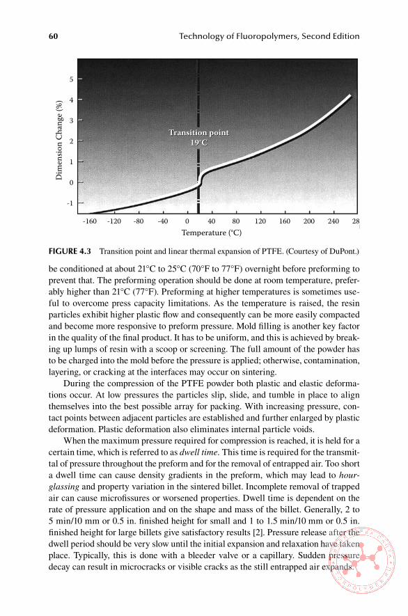
60 Technology of Fluoropolymers, Second Edition
be conditioned at about 21°C to 25°C (70°F to 77°F) overnight before preforming to prevent that. The preforming operation should be done at room temperature, prefer-ably higher than 21°C (77°F). Preforming at higher temperatures is sometimes use-ful to overcome press capacity limitations. As the temperature is raised, the resin particles exhibit higher plastic flow and consequently can be more easily compacted and become more responsive to preform pressure. Mold filling is another key factor in the quality of the final product. It has to be uniform, and this is achieved by break-ing up lumps of resin with a scoop or screening. The full amount of the powder has to be charged into the mold before the pressure is applied; otherwise, contamination, layering, or cracking at the interfaces may occur on sintering.
During the compression of the PTFE powder both plastic and elastic deforma-tions occur. At low pressures the particles slip, slide, and tumble in place to align themselves into the best possible array for packing. With increasing pressure, con-tact points between adjacent particles are established and further enlarged by plastic deformation. Plastic deformation also eliminates internal particle voids.
When the maximum pressure required for compression is reached, it is held for a certain time, which is referred to as dwell time. This time is required for the transmit-tal of pressure throughout the preform and for the removal of entrapped air. Too short a dwell time can cause density gradients in the preform, which may lead to hour-glassing and property variation in the sintered billet. Incomplete removal of trapped air can cause microfissures or worsened properties. Dwell time is dependent on the rate of pressure application and on the shape and mass of the billet. Generally, 2 to 5 min/10 mm or 0.5 in. finished height for small and 1 to 1.5 min/10 mm or 0.5 in. finished height for large billets give satisfactory results [2]. Pressure release after the dwell period should be very slow until the initial expansion and relaxation have taken place. Typically, this is done with a bleeder valve or a capillary. Sudden pressure decay can result in microcracks or visible cracks as the still entrapped air expands.
Temperature (°C)
Transition point19°C
Transition point19°C
Dim
ensio
n Ch
ange
(%)
28024020016012080400-40-80-120-160
5
4
3
2
1
0
-1
FiGURe 4.3 Transition point and linear thermal expansion of PTFE. (Courtesy of DuPont.)
5
4
� • з � с
" u 1 .§ с • .е Q
о
·1
·160 ·110 .ео .40 о .. 110 160 100 140
Processing and Applications of Commercial Fluoroplastics 61
After preforming, there are still residual stresses and entrapped air in the pre-formed part, which invariably causes cracking mainly during the initial stage of sin-tering. The removal of entrapped air, or degassing, requires some time called resting time, which depends mainly on the wall thickness.
4.1.1.1.2 SinteringThe purpose of the sintering operation is to convert the preform into a product with increased strength and reduced fraction of voids. Massive billets are generally sin-tered in an air-circulating oven heated to 365°C to 380°C (689°F to 716°F). Both the sintering temperature and time have a critical effect on the degree of coalescence, which in turn affects the final properties of the product.
Sintering has two stages and consists of a variety of processes. During the first stage, the preform expands up to about 25% of its volume as its temperature is increased to and above the melting point of the virgin resin (about 342°C, or 648°F). The next stage is coalescence of particles in which voids are eliminated. After that, the contacting surfaces of adjacent particles fuse and eventually melt. The latter pro-cess gives the part its strength. After reaching the melting point, the resin changes from a highly crystalline material to an almost transparent amorphous gel. When the first stage is completed, the billet becomes translucent, but it will require additional time to become fully sintered. This time depends not only on the sintering tempera-ture but also on conditions at which the part was preformed and on the type of resin. High pressures and small particle size facilitate fusion. As it is with preform pres-sure, sintering time eventually reaches a point beyond which there is no significant improvement in physical properties to justify longer sintering.
During sintering some degradation of the polymer takes place. Prolonging the process beyond the required time or using very high sintering temperature will invariably result in excessive degradation and considerable worsening of properties. To achieve a uniform heat distribution in the oven, turbulent airflow is required. Variability of heat distribution can cause billet distortion or even cracking. Massive billets should be loaded into the oven at maximum 100°C (182°F) to avoid thermal shock. A holding time of 1 to 2 hours before heat-up is usually required for the tem-perature to reach equilibrium.
The heating rate is very critical for the quality of the final product. Because of the very low thermal conductivity of PTFE resin, the billets have to be heated slowly to the sintering temperature, or cracking may occur even before the resin is fully melted. The highest heating rate a given preform will tolerate depends on a complex interaction of many factors. Major parameters include thermal gradient (difference between the ambient temperature in the oven and the temperature in the midpoint of the preform wall) and the rate of internal stress relaxation. The thermal gradient, in turn, is related to the heating rate and the wall thickness. Internal stresses in the pre-form originate in the preforming process and are dependent mainly on the preform pressure, closure rate, and preform temperature. Normal heating rate for large billets is 28°C (50°F) per hour up to 300°C (572°F), at which point it is reduced to 6°C to 10°C (11°F to 18°F) per hour.
A proper rate for a given set of billet geometry and preforming conditions is usually determined experimentally. Another way to minimize thermal gradient is to
62 Technology of Fluoropolymers, Second Edition
introduce a series of hold periods. In this method a higher heating rate is used in the early phase of the heat-up cycle. Hold periods used between temperatures of 290°C and 350°C (554°F and 662°F) ensure a minimum temperature gradient through the melting transition and minimize any tendency to crack due to the about 10% volume change associated with melting.
At the point when the billet is in the gel state, the particles coalesce, and the voids are eliminated. However, the rate of sintering near the melting point is very slow. To achieve more commercially acceptable sintering rates, the temperatures used for that purpose are in the range between 365°C and 380°C (689°F and 716°F). For massive billets, temperatures above 385°C (725°F) for virgin PTFE and 370°C (698°F) for filled compounds should be avoided since thermal degradation above these temperatures becomes significant. The time at the peak temperature depends on the wall thickness, type of resin used, and the method of sintering. Generally, pro-longed sintering times have beneficial effects on properties, particularly on dielectric strength, provided that no significant degradation takes place. Typical times for a complete sintering are fairly constant—about 2 hours after the resin has reached its optimum sintering temperature. Once the oven has reached the sintering tempera-ture, it takes about 1 to 1.5 hours to transmit the heat through each centimeter of thickness. As a rule of thumb, the time at sintering temperature should be 1.0 hour/cm or 0.4 in. of diameter for solid billets and 1.4 hour/cm or 0.4 in. of wall thickness for billets with a small hole in the middle. For small parts, sintering times of 0.8 hour/cm of wall thickness are adequate. Figure 4.4 illustrates production sintering ovens, and sintered billets are shown in Figure 4.5.
After sintering, the molten billet is cooled to the room temperature in a controlled fashion. As the freezing range of 320°C to 325°C (608°F to 617°F) is reached, crys-tallization starts to happen. The degree of crystallization in the cooled-down part depends on the cooling rate. Since a majority of properties depends on the degree of crystallinity, the cooling rate has to be closely controlled to achieve the desired results. The effect of cooling rate on crystallinity is shown in Table 4.2 [3]. Melt strength and wall thickness are the key factors in determining the cooling rate. Typi-cally, cooling rates between 8°C (14°F) per hour and 15°C (27°F) per hour are satis-factory for larger billets. Because of low thermal conductivity, slow cooling rates are necessary to avoid cracking due to excessive thermal gradients. This is particularly important during the transition in the freezing zone since stresses caused by a rapid volume change can tear the melt apart. Therefore, slower rates are maintained until the inside of the wall is below the freezing point and the center of the billet is crystal-lized. Then, faster cooling rates, about 50°C (90°F) per hour, can be used since the sintered part can tolerate higher thermal gradients [3].
Massive moldings often require annealing during the cooling period to mini-mize thermal gradients and to relieve any residual stresses. The temperature range for annealing is typically from 290°C to 325°C (554°F to 617°F). The temperature at which the annealing is carried out is very critical. If annealing is done in the temper-ature range 310°C to 325°C (590°F to 617°F), the molding exhibits a high degree of crystallinity, which may not always be desirable. The product is highly opaque and has low tensile strength, high stiffness, and high specific gravity. If a lower degree of crystallinity is desired, annealing should be done at 290°C (554°F) [3].
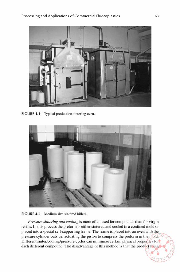
Processing and Applications of Commercial Fluoroplastics 63
Pressure sintering and cooling is more often used for compounds than for virgin resins. In this process the preform is either sintered and cooled in a confined mold or placed into a special self-supporting frame. The frame is placed into an oven with the pressure cylinder outside, actuating the piston to compress the preform in the mold. Different sinter/cooling/pressure cycles can minimize certain physical properties for each different compound. The disadvantage of this method is that the product has a
FiGURe 4.4 Typical production sintering oven.
FiGURe 4.5 Medium size sintered billets.

64 Technology of Fluoropolymers, Second Edition
decreased dimensional stability due to internal stresses. Stress relieving can offset this disadvantage, but it compromises the desired higher properties. Since melting point of PTFE increases with pressure (Figure 4.6), the sintering temperature has to be adjusted accordingly [3].
Billets are almost always subjected to some kind of finishing. The most frequent finishing is by machining. The machinery used for PTFE is the same as for other plastics. The achievable dimensional tolerances depend mainly on the quality of the cutting edge of the tools used, which controls the heat generation. At any rate, cool-ing is necessary to remove excess heat. To achieve very close tolerances, parts have to be stress relieved prior to machining above the expected service temperature. The common practice is to use a holding time of 1 hour/25 mm (1 in.) of thickness, fol-lowed by slow cooling.
Table 4.2effect of Cooling Rate on Polytetrafluoroethylene Crystallinity
Cooling Rate °C/min % Crystallinity
Quenched in ice water 45
5 54
1 56
0.5 58
0.1 62
Source: Compression Moulding, Technical Information, Publication H-59487, 05/95, DuPont, Wilmington, DE, 1995 (With permission). Copyright © 1979–2005. E.I. duPont de Nemours & Co. All rights reserved.
420
Tem
pera
ture
(°C
)
400
380
360
340
320
3000 20 40
Pressure(N/mm2)60 80 100
FiGURe 4.6 Dependence of PTFE melting point on pressure. (From Compression Mould-ing, Technical Information, Publication H-59487, 05/95, E.I. Du Pont de Nemours & Co, Wilmington, DE, p. 17, 1995. With permission.)
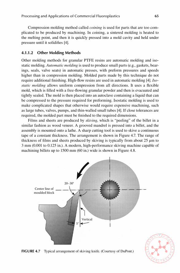
Processing and Applications of Commercial Fluoroplastics 65
Compression molding method called coining is used for parts that are too com-plicated to be produced by machining. In coining, a sintered molding is heated to the melting point, and then it is quickly pressed into a mold cavity and held under pressure until it solidifies [4].
4.1.1.2 other Molding Methods
Other molding methods for granular PTFE resins are automatic molding and iso-static molding. Automatic molding is used to produce small parts (e.g., gaskets, bear-ings, seals, valve seats) in automatic presses, with preform pressures and speeds higher than in compression molding. Molded parts made by this technique do not require additional finishing. High-flow resins are used in automatic molding [4]. Iso-static molding allows uniform compression from all directions. It uses a flexible mold, which is filled with a free-flowing granular powder and then is evacuated and tightly sealed. The mold is then placed into an autoclave containing a liquid that can be compressed to the pressure required for preforming. Isostatic molding is used to make complicated shapes that otherwise would require expensive machining, such as large tubes, valves, pumps, and thin-walled small tubes [4]. If close tolerances are required, the molded part must be finished to the required dimensions.
Films and sheets are produced by skiving, which is “peeling” of the billet in a similar fashion as wood veneer. A grooved mandrel is pressed into a billet, and the assembly is mounted onto a lathe. A sharp cutting tool is used to skive a continuous tape of a constant thickness. The arrangement is shown in Figure 4.7. The range of thickness of films and sheets produced by skiving is typically from about 25 μm to 3 mm (0.001 to 0.125 in.). A modern, high-performance skiving machine capable of machining billets up to 1500 mm (60 in.) wide is shown in Figure 4.8.
Center line ofmoulded block
20–30°
5°Vertical
FiGURe 4.7 Typical arrangement of skiving knife. (Courtesy of DuPont.)
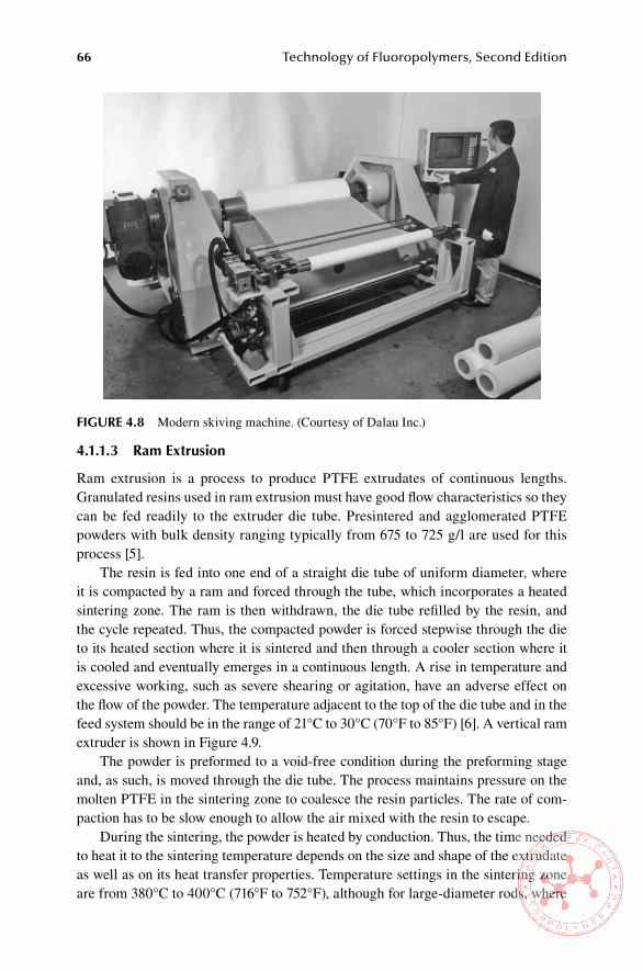
66 Technology of Fluoropolymers, Second Edition
4.1.1.3 Ram extrusion
Ram extrusion is a process to produce PTFE extrudates of continuous lengths. Granulated resins used in ram extrusion must have good flow characteristics so they can be fed readily to the extruder die tube. Presintered and agglomerated PTFE powders with bulk density ranging typically from 675 to 725 g/l are used for this process [5].
The resin is fed into one end of a straight die tube of uniform diameter, where it is compacted by a ram and forced through the tube, which incorporates a heated sintering zone. The ram is then withdrawn, the die tube refilled by the resin, and the cycle repeated. Thus, the compacted powder is forced stepwise through the die to its heated section where it is sintered and then through a cooler section where it is cooled and eventually emerges in a continuous length. A rise in temperature and excessive working, such as severe shearing or agitation, have an adverse effect on the flow of the powder. The temperature adjacent to the top of the die tube and in the feed system should be in the range of 21°C to 30°C (70°F to 85°F) [6]. A vertical ram extruder is shown in Figure 4.9.
The powder is preformed to a void-free condition during the preforming stage and, as such, is moved through the die tube. The process maintains pressure on the molten PTFE in the sintering zone to coalesce the resin particles. The rate of com-paction has to be slow enough to allow the air mixed with the resin to escape.
During the sintering, the powder is heated by conduction. Thus, the time needed to heat it to the sintering temperature depends on the size and shape of the extrudate as well as on its heat transfer properties. Temperature settings in the sintering zone are from 380°C to 400°C (716°F to 752°F), although for large-diameter rods, where
FiGURe 4.8 Modern skiving machine. (Courtesy of Dalau Inc.)
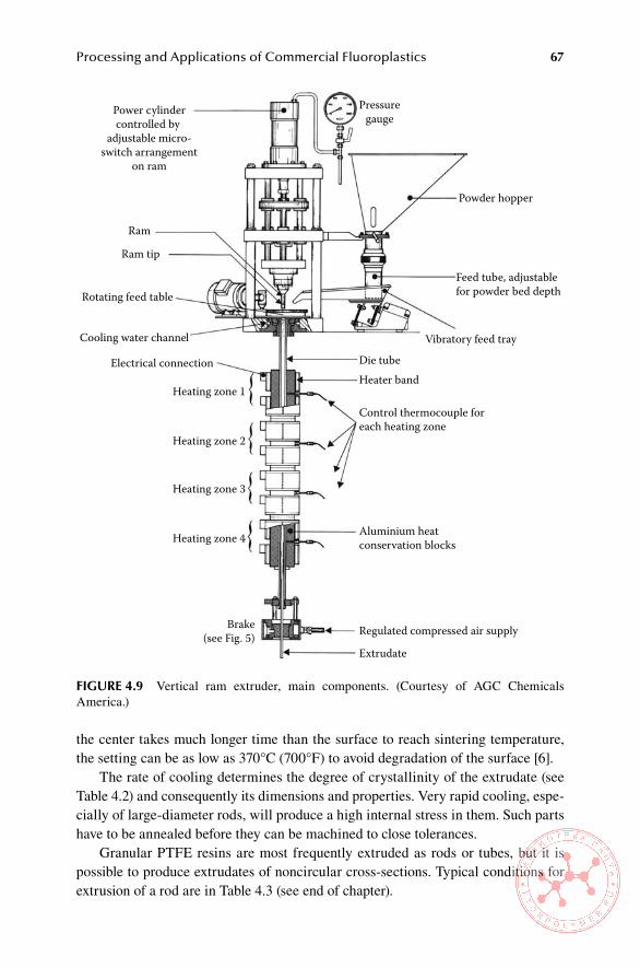
Processing and Applications of Commercial Fluoroplastics 67
the center takes much longer time than the surface to reach sintering temperature, the setting can be as low as 370°C (700°F) to avoid degradation of the surface [6].
The rate of cooling determines the degree of crystallinity of the extrudate (see Table 4.2) and consequently its dimensions and properties. Very rapid cooling, espe-cially of large-diameter rods, will produce a high internal stress in them. Such parts have to be annealed before they can be machined to close tolerances.
Granular PTFE resins are most frequently extruded as rods or tubes, but it is possible to produce extrudates of noncircular cross-sections. Typical conditions for extrusion of a rod are in Table 4.3 (see end of chapter).
Power cylindercontrolled by
adjustable micro-switch arrangement
on ram
Ram
Ram tip
Rotating feed table
Cooling water channel
Electrical connection
Heating zone 1
Heating zone 2
Heating zone 3
Heating zone 4
Extrudate
Regulated compressed air supply
Aluminium heatconservation blocks
Control thermocouple foreach heating zone
Heater bandDie tube
Vibratory feed tray
Feed tube, adjustablefor powder bed depth
Powder hopper
Pressuregauge
Brake(see Fig. 5)
FiGURe 4.9 Vertical ram extruder, main components. (Courtesy of AGC Chemicals America.)

68 Technology of Fluoropolymers, Second Edition
4.1.2 ProcessIng of fIne Powders
Fine powder resins are extremely sensitive to shear, and the sheared polymer cannot be processed. Because of that they have to be handled with great care during trans-port and processing.
Most commonly, fine powder resins are processed in the form of a “paste.” Such a paste is prepared by mixing the powder with 15% to 25% hydrocarbon lubricant, such as kerosene, white oil, or naphtha, with the resultant blend appearing much like the powder alone [7].
Fine powder resins are shipped in specially constructed drums that typically hold 23 kg (50 lb) of resin. These shallow, cylindrical drums are designed to mini-mize compaction and shearing of the resin during shipment and storage. To further assure that the compaction is kept at an absolute minimum, the resin must be kept at a temperature below 19°C (66°F), its transition point, during shipping and ware-house storage. Prior to blending with lubricants, the resin should be stored below its transition temperature for 24 hours. A safe storage temperature for most resins is 15°C (60°F). Generally, the particles form agglomerates, spherical in shape with an average size of 500 μm. If lumps have formed during shipping, the resin should be poured through a four-mesh screen immediately prior to blending. To prevent shearing, the screen should be vibrated gently up and down. Sharp objects, such as scoops, should not be used to remove the resin because they could shear and ruin the soft resin particles. It is best to avoid screening unlubricated powder unless it is absolutely necessary.
Table 4.3example of extrusion Conditions for a Rod (Diameter 10 mm)Die Tube
Diameter 10.6 mm
Unheated length at top of die tube 90 mm
Heated length 900 mm
Unheated length at bottom of die tube 400 mm
Total length 1550 mm
Heated length/diameter 85:1
Water cooling Over top
60 mm
heating arrangements Four separately controlled heated zones,each with 2/1.5 kW heater bands.
Temperature profile (top) Zone 1 380oC
Zone 2 400oC
Zone 3 400oC
(bottom) Zone 4 350oC
Source: Adapted from Processing Guide for Fine Powder Resins, Publication H-21211-2, E. I. Du Pont de Nemours & Co., Inc., Wilmington, DE, p. 4. (1994) (With permission).

Processing and Applications of Commercial Fluoroplastics 69
4.1.2.1 blending with lubricants and Pigments
Lubricants enable PTFE fine powders to be processed on commercial equipment. Liquids with a viscosity between 0.5 and 5 cP are preferred, although more viscous liquids are used occasionally. When selecting a lubricant, its ability to be incorpo-rated easily into the blend and to vaporize completely and rapidly in a later process-ing step without leaving residues that would discolor the product or adversely affect its properties is important. The amounts of lubricant added are typically 16% to 19% of the total weight of the mix.
For colored products, pigments may be added during blending. These can be added dry directly to the powder prior to the addition of the lubricant or as a wet blend in the lubricant. In the latter case, the pigment dispersion is added with the remaining lubricant. All blending operations must be performed in an area in which the temperature is maintained below the PTFE transition temperature of 19°C (66°F), and the relative humidity should be kept at approximately 50%. A high level of cleanliness and an explosion-proof environment are additional requirements to assure high quality and safety.
Blending of small batches, up to about 4.5 kg (10 lb) is most frequently done in wide-mouth jars that are placed on horizontal rollers tumbling at approximately 15 rpm for about 20 min. Larger, commercial batches, sizes typically 10 to 136 kg (22 to 300 lb) are often prepared in twin-shell blenders (Figure 4.10) by tumbling 15 min. at 24 rpm. The blend is screened again, is transferred into a storage vessel, and is allowed to age for at least 12 hours [8].
FiGURe 4.10 Twin shell blender. (Courtesy of Patterson-Kelley Co.)
70 Technology of Fluoropolymers, Second Edition
4.1.2.2 Preforming
The properly aged lubricated powder is usually preformed at room temperature into a billet of the size required by the equipment in which it is to be later processed. Preforming removes air from the material and compacts it so that it has a sufficient integrity for handling during the manufacturing process. Preforming pressures are on the order of 0.7 MPa (100 psig) in the initial stage of the cycle and may increase up to 2 MPa (300 psig). Higher pressures do not increase compaction and may cause the lubricant to be squeezed out [8]. The compaction rate is initially up to 250 mm (10 in.) per min and is reduced toward its end. The finished preform is rather frag-ile and must be stored in a polyvinyl chloride (PVC) or polymethyl methacrylate (PMMA) tube for protection against damage and contamination.
4.1.2.3 extrusion
The extrusion step is performed at temperatures above 19°C (66°F), the first transi-tion point of the resin, where it is highly deformable and can be extruded smoothly. The resin preform is placed in the extrusion cylinder, which is kept at a temperature of 38°C (100°F) for several minutes to heat up to the higher temperature.
Unsintered rod and tape for packing and unsintered tape for thread sealing and cable wrapping together represent one of the largest applications for this technology. Other applications are sintered thin-walled tubing and wire coating.
Extrusion of an unsintered rod is the simplest process for paste extrusion of PTFE fine powders. The extrusion is done by a simple hydraulic ram extruder with a total available thrust ranging from 10 to 20 tons. The ram speed is adjustable up to a maximum of 50 to 100 mm/min (2 to 4 in./min). The ram forces the lubricated powder through the orifice of the die. The head of the ram is usually fitted with a PTFE seal to prevent polymer from flowing back along the ram. The surfaces of the extrusion cylinder and die are made from corrosion-resistant steel and are highly polished. The pressures during the rod extrusion are normally in the range of 10 to 15 MN/m2 (1500 to 2000 psi). The diameter of the extrusion cylinder is designed to accommodate the required size of the extrudate and the type of polymer used. The usual extrusion cylinder diameters are between 40 and 150 mm (1.5 and 6 in.). The die consists of two parts: a conical and a parallel section. The conical part is more important, as the reduction in area between cone entry and exit determines the amount of work done on the polymer and, hence, to a high degree, the properties of the extrudate. The cone angle has also some effect on the extrudate and is most com-monly 30°, although larger angles are used for large-diameter cylinders. The length/diameter ratio of the die parallel (die land), which also has some effect on the proper-ties of the extrudate, may vary from 5 to 10 times the exit diameter. An example of conditions for rod extrusion is in Table 4.3.
Extruded rod can be either used for packing or converted into tape by calender-ing. Rod for packings is sometimes used with the lubricant still in it. If the lubricant is to be removed, this may be done in a simple in-line oven immediately after the extruder or in a separate batch oven.

Processing and Applications of Commercial Fluoroplastics 71
4.1.2.3.1 Manufacture of Unsintered TapeThe production of unsintered tape from extruded rod normally consists of the fol-lowing sequence of operations:
1. Calendering 2. Removal of lubricant 3. Slitting 4. Reeling
The rod used in this method has a relatively large diameter, typically 10 to 15 mm (0.4 to 0.6 in.), and is calendered in a single pass to a tape about 100 to 200 mm (4 to 8 in.) wide and 0.075 to 0.01 mm (0.003 to 0.004 in.) thick, which is subsequently slit to several tapes of desired width. No advantage has been found in using multiple-stage calendering [9].
The rod is fed into the nip of the calender by means of a guide tube that prevents it from wandering and consequent variation in the width of the calendered tape. A tape with straight edges and controlled width is produced when a fishtail guide made from metals (e.g., aluminum) or plastics (e.g., acetal) is used successfully [9].
The calender rolls are heated to temperatures up to 80°C (176°F) to produce a smooth, strong tape. They may be heated either electrically or by circulating hot water or oil [9]. Production speeds of 0.05 to 0.5 m/s (10 to 100 ft/min) are quite common.
The thickness of the calendered tape depends mainly on the calender nip setting. The tape width depends on several factors, such as lubricant type and content, reduc-tion ratio and die geometry during the extrusion, and the speed and temperature of the calender rolls [9].
Normally, the lubricant is removed by passing the calendered tape through a heated tunnel oven. If the lubricant used in the mixture has a very high boiling point, such as mineral oil, it may be removed by passing the calendered tape through a degreasing bath containing hot vapor of trichloroethylene or other suitable solvent. The slow output rate of this process and safety and health hazards associated with this method rarely offset the advantages of using heavy oils, such as virtually no loss of lubricant by evaporation between extrusion and calendering and the amount of work done on the polymer as a result of the much higher viscosity of the paste. Therefore, this technique is seldom used and only in cases where it is absolutely necessary.
After the lubricant is removed, the tape is slit to the desired width by leading it under a slight tension over stationary or rotating cutting blades. The slit tape is reeled onto small spools. An outline of the process is shown in Figure 4.11.
4.2 aPPliCaTions FoR PTFe
About one half of the PTFE resin produced is used in electrical and electronic appli-cations [10] with major use for insulation of hookup wire for military and aerospace electronic equipment. PTFE is also used as insulation for airframe and computer wires, as “spaghetti” tubing, and in electronic components. PTFE tape is used for wrapping coaxial cables. An example of an application of PTFE wrap tape is shown in Figure 4.12.
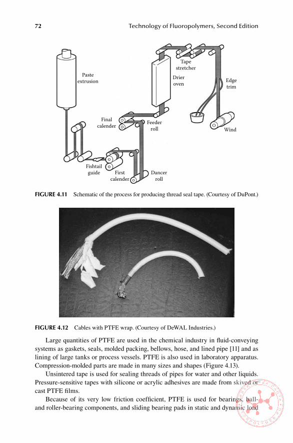
72 Technology of Fluoropolymers, Second Edition
Large quantities of PTFE are used in the chemical industry in fluid-conveying systems as gaskets, seals, molded packing, bellows, hose, and lined pipe [11] and as lining of large tanks or process vessels. PTFE is also used in laboratory apparatus. Compression-molded parts are made in many sizes and shapes (Figure 4.13).
Unsintered tape is used for sealing threads of pipes for water and other liquids. Pressure-sensitive tapes with silicone or acrylic adhesives are made from skived or cast PTFE films.
Because of its very low friction coefficient, PTFE is used for bearings, ball- and roller-bearing components, and sliding bearing pads in static and dynamic load
FiGURe 4.12 Cables with PTFE wrap. (Courtesy of DeWAL Industries.)
Pasteextrusion
Fishtailguide First
calenderDancer
roll
Finalcalender Feeder
roll
Drieroven
Tapestretcher
Edgetrim
Wind
FiGURe 4.11 Schematic of the process for producing thread seal tape. (Courtesy of DuPont.)
о о
о

Processing and Applications of Commercial Fluoroplastics 73
supports [11]. Piston rings of filled PTFE in nonlubricated compressors permit oper-ation at lower power consumption or at increased capacities [12].
The recently developed modified PTFE (e.g., Teflon NXT)—because of its improved processing, lower creep, improved permeation, less porosity, and better insulation than standard PTFE—finds use in pipe and vessel linings, gaskets and seals, fluid-handling components, wafer processing, and electric and electronic indus-tries. An example of a molded part from modified PTFE is shown in Figure 4.14.
Since PTFE is highly inert and nontoxic, it finds use in medical applications such as cardiovascular grafts, heart patches, and ligaments for knees [12].
Highly porous membranes are prepared by a process based on the fibrillation of high-molecular-weight PTFE [13] (Figure 4.15). Since they have a high permeability for water vapor and none for liquid water, it is combined with fabrics and used for
FiGURe 4.14 Molded part from modified PTFE. (Courtesy of DeWAL Industries.)
FiGURe 4.13 PTFE molded parts. (Courtesy of Dalau Inc.)
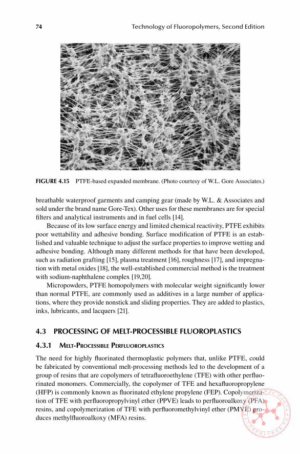
74 Technology of Fluoropolymers, Second Edition
breathable waterproof garments and camping gear (made by W.L. & Associates and sold under the brand name Gore-Tex). Other uses for these membranes are for special filters and analytical instruments and in fuel cells [14].
Because of its low surface energy and limited chemical reactivity, PTFE exhibits poor wettability and adhesive bonding. Surface modification of PTFE is an estab-lished and valuable technique to adjust the surface properties to improve wetting and adhesive bonding. Although many different methods for that have been developed, such as radiation grafting [15], plasma treatment [16], roughness [17], and impregna-tion with metal oxides [18], the well-established commercial method is the treatment with sodium-naphthalene complex [19,20].
Micropowders, PTFE homopolymers with molecular weight significantly lower than normal PTFE, are commonly used as additives in a large number of applica-tions, where they provide nonstick and sliding properties. They are added to plastics, inks, lubricants, and lacquers [21].
4.3 PRoCessinG oF MelT-PRoCessible FlUoRoPlasTiCs
4.3.1 melt-ProcessIble PerfluoroPlastIcs
The need for highly fluorinated thermoplastic polymers that, unlike PTFE, could be fabricated by conventional melt-processing methods led to the development of a group of resins that are copolymers of tetrafluoroethylene (TFE) with other perfluo-rinated monomers. Commercially, the copolymer of TFE and hexafluoropropylene (HFP) is commonly known as fluorinated ethylene propylene (FEP). Copolymeriza-tion of TFE with perfluoropropylvinyl ether (PPVE) leads to perfluoroalkoxy (PFA) resins, and copolymerization of TFE with perfluoromethylvinyl ether (PMVE) pro-duces methylfluoroalkoxy (MFA) resins.
FiGURe 4.15 PTFE-based expanded membrane. (Photo courtesy of W.L. Gore Associates.)

Processing and Applications of Commercial Fluoroplastics 75
4.3.1.1 Copolymers of Tetrafluoroethylene and hexafluoropropylene (FeP)
FEP resins are available in low melt viscosity, as extrusion grade, in intermediate viscosity, in high melt viscosity, and as aqueous dispersions [22]. They can be pro-cessed by techniques commonly used for thermoplastics, such as extrusion, injection molding, rotational molding, dip, slush molding, and powder and fluidized bed coat-ing [23], and can be expanded into foams [24]. Compression and transfer molding of FEP resins can be done, but with some difficulty. Extrusion of FEP is used for primary insulation or cable jackets and for tubing and films.
Processing temperatures used for FEP resins are usually up to 427°C (800°F), at which temperatures highly corrosive products are generated. Therefore, the parts of the processing equipment that are in contact with the melt must be made of special corrosion-resistant alloys to assure a trouble-free operation.
4.3.1.2 Copolymers of Tetrafluoroethylene and Perfluoropropylvinyl ether (PFa)
PFA can be processed by standard techniques used for thermoplastics, such as extru-sion and injection molding and transfer molding at temperatures up to 425ºC (797ºF). High processing temperatures are required because PFA has a high melt viscosity with activation energy lower than most thermoplastics, 50 kJ/mol [25]. Extrusion and injection molding are done at temperatures typically above 390°C (734°F) and at relatively high shear rates. For these processing methods PFA grades with high melt flow indexes (MFIs) (i.e., with lower molecular weights) are used. Although PFA is thermally a very stable polymer, it still is subject to thermal degradation at process-ing temperatures, the extent of which depends on temperature, residence time, and the shear rate. Thermal degradation occurs mainly from the end groups; chain scis-sion becomes evident at temperatures above 400°C (752°F) depending on the shear rate. Thermal degradation usually causes discoloration and bubbles [25]. PFA can be extruded into films, tubing, rods, and foams [24].
Transfer molding of PFA is done at temperatures in the range of 350°C to 380°C (662°F to 716°F) and at lower shear rates. At these conditions chain scission does not occur. The gaseous products evolving from the thermal degradation of the end groups are practically completely dissolved in the melt since the molded parts are cooled under pressure. For transfer molding, PFA resins with lower MFIs (i.e., higher molecular weights) are preferred [25]. Because at the high processing temperatures large amounts of highly corrosive products are generated, the parts of the equipment have to be made from corrosion-resistant alloys to assure a trouble-free operation. PFA can also be processed as an aqueous dispersion (see Chapter 6).
4.4 PRoCessinG oF oTheR MelT-PRoCessible FlUoRoPlasTiCs
4.4.1 coPolymers of ethylene and tetrafluoroethylene (etfe)
Ethylene tetrafluoroethylene copolymers can be readily fabricated by a variety of melt-processing techniques [26]. They have a wide processing window, in the range
76 Technology of Fluoropolymers, Second Edition
280°C to 340°C (536°F to 644°F), and can be extruded into films, tubing, and rods or as thin coating on wire and cables. Injection molding of ETFE into thin sections is considerably easier than injection molding of melt-processible perfluoropolymers because the former has critical shear rate at least two orders of magnitude greater than perfluoropolymers. When molding thick sections (thickness greater than 5 mm, or approximately 0.2 in.), it is important to consider melt shrinkage occurring during freezing, which can be as great as 6% [27].
Coatings can be prepared by hot flocking, in which the heated part is dipped into a fluidized bed of ETFE powder and then is removed to cool. ETFE coatings can also be applied by other powder coating methods (e.g., electrostatically) or by spraying of water- or solvent-based suspensions followed by drying and baking [27].
Welding of ETFE parts can be done easily by spin welding, ultrasonic welding, and conventional butt-welding using flame and ETFE rod. The resins bond readily to untreated metals, but chemical etch corona and flame treatment can be used to increase adhesion further [28].
ETFE resins are very often compounded with varied ingredients (e.g., fiberglass, bronze powder) or modified during their processing. The most significant modifica-tion is cross-linking by peroxides or ionizing radiation. The cross-linking results in improved mechanical properties, higher upper-use temperatures, and a better cut-through resistance without significant sacrifice of electrical properties or chemical resistance [27]. The addition of fillers improves creep resistance, improves friction and wear properties, and increases softening temperature [29]. ETFE can also be processed as an aqueous dispersion; however, at this writing no ETFE dispersions are commercially available, as they were discontinued.
4.4.2 PolyVInylIdene fluorIde (PVdf)
PVDF resins for melt processing are supplied as powders or pellets with a rather wide range of melt viscosities. Lower viscosity grades are used for injection molding of complex parts, while the low viscosity grades have high enough melt strength for the extrusion of profiles, rods, tubing, pipe, film, wire insulation, and monofilament. PVDF extrudes very well, and there is no need to use lubricants or heat stabiliz-ers [30]. The equipment for the melt processing of PVDF is the same as that for PVC or polyolefins, as during normal processing of PVDF no corrosive products are formed. Extrusion temperatures vary between 230°C and 290°C (446°F and 554°F), depending on the equipment and the profile being extruded. Water quenching is used for wire insulation, tubing, and pipe, whereas sheet and cast film from slit dies are cooled on polished steel rolls kept at temperatures between 65°C and 140°C (149°F and 284°F). Monofilament is extrusion-spun into a water bath and then oriented and heat-set at elevated temperatures [31]. PVDF films can be monoaxially and biaxially oriented.
PVDF resins can be molded by compression, transfer, and injection molding in conventional molding equipment. The mold shrinkage can be as high as 3% due to the semicrystalline nature of PVDF. Molded parts often require annealing at tem-peratures between 135°C and 150°C (275°F and 302°F) to increase dimensional sta-bility and to release internal stresses [31].
Processing and Applications of Commercial Fluoroplastics 77
Parts from PVDF can be machined, sawed, coined, metallized, and fusion bonded more easily than most other thermoplastics. Fusion bonding usually yields a weld line that is as strong as the part. Adhesive bonding of PVDF parts can be done; epoxy resins produce good bonds [31]. Because of a high dielectric constant and loss factor, PVDF can be readily melted by radiofrequency and dielectric heating. This is the basis for some fabrication and joining techniques [32].
PVDF can be coextruded and laminated, but the process has its technical chal-lenges in matching the coefficients of thermal expansion, melt viscosities, and layer adhesion. Special tie-layers, often from blends of polymers compatible with PVDF, are used to achieve bonding [33,34].
4.4.3 PolychlorotrIfluoroethylene (Pctfe)
PCTFE can be processed by most of the techniques used for thermoplastics. Process-ing temperatures can be as high as 350°C (662°F) for injection molding with melt temperatures leaving the nozzle in the range of 280°C to 305°C (536°F to 579°F). In compression molding, process temperatures up to 315°C (599°F) and pressures up to 69 MPa (10,000 psi) are required. Since relatively high molecular weight resins are required for adequate mechanical properties, the melt viscosities are somewhat higher than those usual in the processing of thermoplastics. The reason is a border-line thermal stability of the melt, which does not tolerate sufficiently high processing temperatures [35].
4.4.4 coPolymers of ethylene and chlorotrIfluoroethylene (ectfe)
The most common form of ethylene chlorotrifluoroethylene is hot-cut pellets, which can be used in all melt-processing techniques, such as extrusion, injection molding, blow molding, compression molding, and fiber spinning [36]. ECTFE is corrosive in melt; the surfaces of machinery that come in contact with the polymer must be lined with a highly corrosion-resistant alloy (e.g., Hastelloy C-276). Recently developed grades with improved thermal stability and acid scavenging can be processed on conventional equipment [37].
Electrostatic powder coating using fine powders and rotomolding and rotolining using very fine pellets are other processing methods. Formulated primers are used to improve adhesion and moisture permeability for powder-coated metal substrates. For rotolining, primers are usually not used [38].
4.4.5 thV fluoroPlastIcs
THV fluoroplastics can be processed by virtually any method used generally for thermoplastics, including extrusion, coextrusion, tandem extrusion, blown film extrusion, blow molding, injection molding, and vacuum forming, and as skived film and solvent casting (only THV 220).
Generally, processing temperatures for THV are comparable to those used for most thermoplastics. In extrusion, melt temperatures at the die are in the 230°C to 250°C (446°F to 482°F) range. These relatively low processing temperatures open new options for combinations of different melts (coextrusion, cross-head extrusion,
78 Technology of Fluoropolymers, Second Edition
co-blow molding) with thermoplastics as well as with various elastomers [39]. Another advantage of the low processing temperatures is that they are generally below the decomposition temperature of the polymer; thus, there is no need to protect equip-ment against corrosion. Yet, as with any fluoropolymer, it is necessary to prevent long residence times in equipment and to purge the equipment after the process is finished. Also, appropriate ventilation is necessary. THV was found to be suitable for coextru-sion with a variety of materials into multilayer structures [40].
THV can be readily processed by blow molding alone or with polyolefins. The olefin layer provides a structural integrity while THV provides chemical resistance and considerably reduced permeation [39].
In injection molding, THV is processed at lower temperatures than other fluo-ropolymers, typically at 200°C to 300°C (392°F to 572°F) with mold temperatures being 60°C to 100°C (140°F to 212°F). Generally, standard injection molding equip-ment is used [41].
THV can be readily bonded to itself and to other plastics and elastomers. It does not require surface treatment, such as chemical etch or corona treatment, to attain good adhesion to other polymers, although in some cases tie-layers are necessary. For bonding THV to elastomers, an adhesion promoter is compounded to the elas-tomer substrate [42].
4.5 aPPliCaTions FoR MelT-PRoCessible FlUoRoPlasTiCs
4.5.1 aPPlIcatIons for feP
The largest proportion of FEP is used in electrical applications, such as hookup wire, interconnecting wire, thermocouple wire, computer wire, and molded parts for electrical and electronic components. Chemical applications include lined tanks, lined pipes and fittings, heat exchangers, overbraided hose, gaskets, component parts of valves, and laboratory ware [43]. Mechanical uses include antistick applications such as conveyor belts and roll covers. FEP film is used in solar-collector windows because of its light weight, excellent weather resistance, high transparency, and easy installation [43]. FEP film is also used for heat-sealing of PTFE-coated fabrics (e.g., architectural fabric). An example of extruded pipes is shown in Figure 4.16.
4.5.2 aPPlIcatIons for Pfa and mfa
Perfluoroalkoxy resins are fabricated into high-temperature electrical insulation and into components and parts requiring long flex life [44]. Certain grades are used in chemical industry for process equipment, liners, specialty tubing, and molded articles. Other uses are bellows and expansion joints, liners for valves, pipes, pumps, and fittings. Examples are shown in Figure 4.17. Extruded PFA films can be oriented and used as such for specialized applications [45]. PFA resins can be processed into injection-, blow-, and compression-molded components. High-purity grades are used in the semiconductor industry for demanding chemical applications [45]. Coated metal parts can be made by powder coating.

Processing and Applications of Commercial Fluoroplastics 79
4.5.3 aPPlIcatIons for coPolymers of ethylene and tetrafluoroethylene
ETFE is used in electrical applications for heat-resistant insulations and jackets of low-voltage power wiring for mass transport systems, for wiring in chemical plants, and for control and instrumentation wiring for utilities [46]. Because ETFE exhibits an excellent cut-through and abrasion resistance, it is used in airframe wire and com-puter hookup wire. Electrical and electronic components, such as sockets, connec-tors, and switch components, are made by injection molding [47]. ETFE has excellent mechanical properties; therefore, it is used successfully in seal glands, pipe plugs, corrugated tubing, fasteners, and pump vanes [46]. Its radiation resistance is a reason for its use in nuclear industry wiring [48]. The lower density of ETFE provides an advantage over perfluoropolymers in aerospace wiring [48].
FiGURe 4.17 Variety of parts for chemical industry from MFA. (Courtesy of Solvay Solexis.)
FiGURe 4.16 Extruded pipes from FEP. (Courtesy of DuPont.)
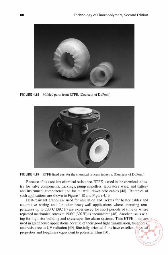
80 Technology of Fluoropolymers, Second Edition
Because of its excellent chemical resistance, ETFE is used in the chemical indus-try for valve components, packings, pump impellers, laboratory ware, and battery and instrument components and for oil well, down-hole cables [48]. Examples of such applications are shown in Figure 4.18 and Figure 4.19.
Heat-resistant grades are used for insulation and jackets for heater cables and automotive wiring and for other heavy-wall applications where operating tem-peratures up to 200°C (392°F) are experienced for short periods of time or where repeated mechanical stress at 150°C (302°F) is encountered [46]. Another use is wir-ing for high-rise building and skyscraper fire alarm systems. Thin ETFE films are used in greenhouse applications because of their good light transmission, toughness, and resistance to UV radiation [49]. Biaxially oriented films have excellent physical properties and toughness equivalent to polyester films [50].
FiGURe 4.19 ETFE lined part for the chemical process industry. (Courtesy of DuPont.)
FiGURe 4.18 Molded parts from ETFE. (Courtesy of DuPont.)

Processing and Applications of Commercial Fluoroplastics 81
Injection-molded parts such as electrical connectors and sockets, distillation column plates and packings, valve bodies pipe, and fitting linings are easily made because ETFE exhibits a low shear sensitivity and wide processing window [49].
ETFE can be extruded continuously into tubing, piping, and rod stock. An example of application of extruded tubing is automotive tubing, which takes advan-tage of its chemical resistance, mechanical strength, and resistance to permeation of hydrocarbons. A high weld factor (more than 90%) is utilized in butt welding of piping and sheet lining of large vessels [49].
ETFE resins in the powder and bead form are rotationally molded into varied structures, such as pump bodies, tanks, and fittings and linings, mostly for the chem-ical process industries. Inserts can be incorporated to provide attachment points or reinforcement [48]. Adhesion to steel, copper, and aluminum can be up to 3 kN/m (5.7 pli) peel force [51].
Carbon-filled ETFE resins (about 20% carbon) exhibit antistatic dissipation and are used in self-limiting heater cables and other antistatic or semiconductive applica-tions [49].
Certain grades of ETFE are used for extruded foams with void contents from 20% to 50%. The closed foam cells are 0.001 to 0.003 in. (0.02 to 0.08 mm) in diam-eter. Special grades of ETFE processed in gas-injection foaming process may have void contents up to 70%. Foamed ETFE is used in electrical applications, mainly in cables, because it exhibits lower apparent dielectric constant and dissipation factor and reduces cable weight.
4.5.4 aPPlIcatIons for PVdf
PVDF is widely used in the chemical industry in fluid-handling systems for solid and lined pipes, fittings, valves, pumps, tower packing, tank liners (Figure 4.20), and woven filter cloth. Because it is approved by the U.S. Food and Drug Administration for food contact, it can be used for fluid-handling equipment and filters in the food,
FiGURe 4.20 Parts from PVDF. (Courtesy of Solvay Solexis.)
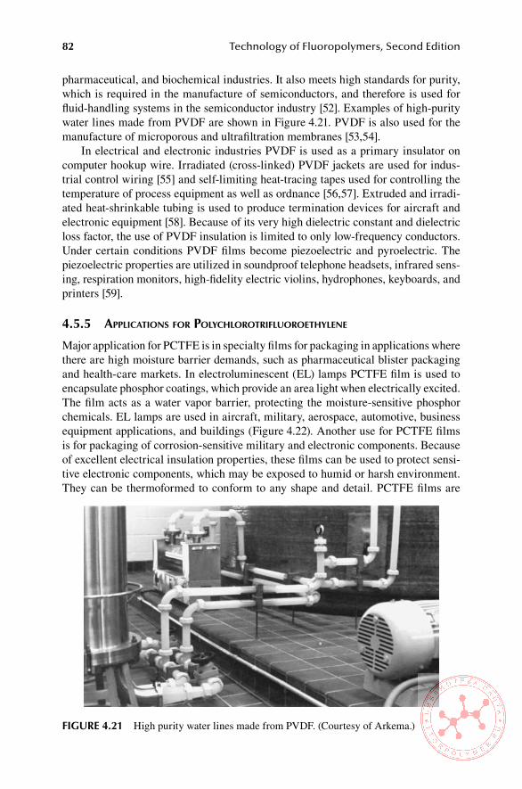
82 Technology of Fluoropolymers, Second Edition
pharmaceutical, and biochemical industries. It also meets high standards for purity, which is required in the manufacture of semiconductors, and therefore is used for fluid-handling systems in the semiconductor industry [52]. Examples of high-purity water lines made from PVDF are shown in Figure 4.21. PVDF is also used for the manufacture of microporous and ultrafiltration membranes [53,54].
In electrical and electronic industries PVDF is used as a primary insulator on computer hookup wire. Irradiated (cross-linked) PVDF jackets are used for indus-trial control wiring [55] and self-limiting heat-tracing tapes used for controlling the temperature of process equipment as well as ordnance [56,57]. Extruded and irradi-ated heat-shrinkable tubing is used to produce termination devices for aircraft and electronic equipment [58]. Because of its very high dielectric constant and dielectric loss factor, the use of PVDF insulation is limited to only low-frequency conductors. Under certain conditions PVDF films become piezoelectric and pyroelectric. The piezoelectric properties are utilized in soundproof telephone headsets, infrared sens-ing, respiration monitors, high-fidelity electric violins, hydrophones, keyboards, and printers [59].
4.5.5 aPPlIcatIons for PolychlorotrIfluoroethylene
Major application for PCTFE is in specialty films for packaging in applications where there are high moisture barrier demands, such as pharmaceutical blister packaging and health-care markets. In electroluminescent (EL) lamps PCTFE film is used to encapsulate phosphor coatings, which provide an area light when electrically excited. The film acts as a water vapor barrier, protecting the moisture-sensitive phosphor chemicals. EL lamps are used in aircraft, military, aerospace, automotive, business equipment applications, and buildings (Figure 4.22). Another use for PCTFE films is for packaging of corrosion-sensitive military and electronic components. Because of excellent electrical insulation properties, these films can be used to protect sensi-tive electronic components, which may be exposed to humid or harsh environment. They can be thermoformed to conform to any shape and detail. PCTFE films are
FiGURe 4.21 High purity water lines made from PVDF. (Courtesy of Arkema.)

Processing and Applications of Commercial Fluoroplastics 83
also used to protect the moisture-sensitive liquid crystal display panels of portable computers [60].
PCTFE films can be laminated to a variety of substrates, such as PVC, poly-ethy-lene-terephtalate glycol (PETG), amorphous polyethylene terephtalate (APET), or polypropylene (PP). Metallized films are used for electronic dissipative and moisture barrier bags for sensitive electronic components (Figure 4.23), for packag-ing of drugs (Figure 4.24), and for medical devices (Figure 4.25).
Other applications for PCTFE are in pump parts, transparent sight glasses, flow-meters, tubes, and linings in the chemical industry and for laboratory ware [61].
4.5.6 aPPlIcatIons for ectfe
The single largest application for ECTFE has been as primary insulation and jacket-ing [62] for voice and copper cables used in building plenums [63]. In automotive applications, ECTFE is used for jackets of cables inside fuel tanks for level sensors, for hookup wires, and in heating cables for car seats. Chemically foamed ECTFE is used in some cable constructions [64]. In the chemical process industry, it is often used in chlorine/caustic environment in cell covers, outlet boxes, lined pipes (Fig-ure 4.26), and tanks.
In the pulp and paper industries, pipes and scrubbers for bleaching agents are lined with ECTFE. Powder-coated tanks, ducts, and other components find use in semiconductor and chemical process industries (Figure 4.27). Monofilament made from ECTFE is used for chemical-resistant filters and screens [65].
Other applications include rotomolded tanks and containers for the storage of corrosive chemicals, such as nitric or hydrochloric acid. Extruded sheets can be thermoformed into various parts, such as battery cases for heart pacemakers
FiGURe 4.22 Electroluminescent lamp with PCTFE film. (Courtesy of Honeywell.)

84 Technology of Fluoropolymers, Second Edition
FiGURe 4.24 Packaging of drugs from barrier films from PCTFE. (Courtesy of Honeywell.)
FiGURe 4.23 Packaging of an electronic component with barrier films from PCTFE. (Courtesy of Honeywell.)

Processing and Applications of Commercial Fluoroplastics 85
FiGURe 4.25 Packaging of medical devices from barrier films from PCTFE. (Courtesy of Honeywell.)
FiGURe 4.26 Parts from ECTFE. (Courtesy of Solvay Solexis.)
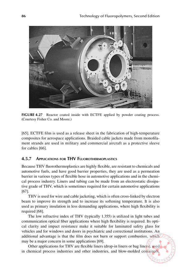
86 Technology of Fluoropolymers, Second Edition
[65]. ECTFE film is used as a release sheet in the fabrication of high-temperature composites for aerospace applications. Braided cable jackets made from monofila-ment strands are used in military and commercial aircraft as a protective sleeve for cables [66].
4.5.7 aPPlIcatIons for thV fluorothermoPlastIcs
Because THV fluorothermoplastics are highly flexible, are resistant to chemicals and automotive fuels, and have good barrier properties, they are used as a permeation barrier in various types of flexible hose in automotive applications and in the chemi-cal process industry. Liners and tubing can be made from an electrostatic dissipa-tive grade of THV, which is sometimes required for certain automotive applications [67].
THV is used for wire and cable jacketing, which is often cross-linked by electron beam to improve its strength and to increase its softening temperature. It is also used as primary insulation in less demanding applications, where high flexibility is required [68].
The low refractive index of THV (typically 1.355) is utilized in light tubes and communication optical fiber applications where high flexibility is required. Its opti-cal clarity and impact resistance make it suitable for laminated safety glass for vehicles and for windows and doors in psychiatric and correctional institutions. An additional advantage is that the film does not burn or support combustion, which may be a major concern in some applications [69].
Other applications for THV are flexible liners (drop-in liners or bag liners), used in chemical process industries and other industries, and blow-molded containers,
FiGURe 4.27 Reactor coated inside with ECTFE applied by powder coating process. (Courtesy Fisher Co. and Moore.)
Processing and Applications of Commercial Fluoroplastics 87
where it enhances the resistance to permeation when combined with a less expensive plastic (e.g., high-density polyethylene [HDPE]), which provides the structural integ-rity [68]. Optical clarity, excellent weatherability, and flexibility make THV suitable as a protection of solar cell surface in solar modules [70].
4.5.8 aPPlIcatIons for hte fluorothermoPlastIcs
HTE resins are suitable for automotive and aerospace wiring, complementing ETFE. The HTE fluoroplastics have similar abrasion resistance and cut-through resistance to ETFE, but they can be processed on standard extrusion and molding equipment and offer a higher LOI than ETFE. Another application of HTE fluoroplastics is in loose-fit tank liners [71].
4.6 PRoCessinG anD aPPliCaTions oF PolYvinYlFlUoRiDe
4.6.1 ProcessIng of PolyVInyl fluorIde
PVF is considered a thermoplastic, but it cannot be processed by conventional ther-moplastic techniques because it is unstable above its melting point. However, it can be fabricated into self-supporting films and coatings by using latent solvents [72]. It can be compression molded, but this method is not commonly used [73]. Because of a large number of hydrogen bonds and a high degree of crystallinity, PVF is insoluble at room temperature. However, some highly polar latent solvents, such as propylene carbonate, dimethylformamide, dimethyl acetamide, butyrolactone, and dimethyl sulfoxide, dissolve it above 100°C (212°F) [72]. The use of latent solvents is the basis of processes to manufacture films and coatings. A latent solvent suitable for that has to have the appropriate volatility to allow the polymer particles to coalesce before complete evaporation.
Structurally modified PVF has been extruded [74]. Thin films are manufactured by extrusion of a dispersion of PVF in a latent solvent [75]. Such dispersion contains usually pigments, stabilizers, plasticizers, and flame retardants as well as deglossing agents if needed. The solvent is removed by evaporation. The extruded film can be biaxially oriented, and the solvent is removed by evaporation only after the orienta-tion is completed.
Homopolymers and copolymers of vinyl fluoride can be applied to substrates as dispersion in a latent solvent or water or by powder coating. Usually, the substrate does not need to be primed [76]. The dispersions may be applied by spraying, reverse roll coating, dip coating, or centrifugal casting. Another method is dipping a hot article into the dispersion below 100°C (212°F). PVF films are most frequently pro-duced by casting on a continuous moving belt.
PVF films often require a surface treatment to improve bonding to other materi-als. Among these are flame treatment [77], electric discharge [78], chemical etching, and plasma treatment [79].
88 Technology of Fluoropolymers, Second Edition
4.6.2 aPPlIcatIons for PolyVInyl fluorIde
PVF is almost exclusively used as film for lamination with a large variety of sub-strates. Its main function is as a protective and decorative coating. PVF films can be made transparent or pigmented to a variety of colors and can be laminated to hard-board, paper, flexible PVC, polystyrene, rubber, polyurethane, and other substrates [80]. These laminates are used for things including wall coverings, aircraft cabin interiors, pipe covering, and duct liners. For covering metal and rigid PVC, the film is first laminated to flat, continuous metal or vinyl sheets using special adhesives, and then the laminate is formed into the desired shapes. The laminates are used for exterior sidings of industrial and residential buildings. Other applications are high-way sound barriers [81], automobile truck and trailer siding [82], vinyl awnings, and backlit signs [83]. On metal or plastic, PVF surfaces serve as a primer coat for paint-ing or adhesive joints [84]. PVF films are used as a release sheet for bag molding of composites from epoxide, polyester, and phenolic resins and in the manufacture of circuit boards [85]. Other uses of PVF films are in greenhouses, flat-plate solar col-lectors, and photovoltaic cells. Dispersions of PVF are used for coating the exterior of steel hydraulic brake tubing for corrosion protection [84].
ReFeRenCes
1. Compression Moulding, Technical Information, Publication H-59487, 05/95, E. I. du Pont de Nemours & Co, Wilmington, DE, p. 3 (1995).
2. Compression Moulding, Technical Information, Publication H-59487, 05/95, E. I. du Pont de Nemours & Co, Wilmington, DE, p. 9 (1995).
3. Compression Moulding, Technical Information, Publication H-59487, 05/95, E. I. du Pont de Nemours & Co, Wilmington, DE, p. 17 (1995).
4. Carlson, D. P. and Schmiegel, N. in Ulmann’s Encyclopedia of Industrial Chemistry (Gerhartz, W., Ed.), Vol. A 11, VCH Publishers, Weinheim, Germany, p. 400 (1988).
5. The Extrusion of PTFE Granular Powders, Technical Service Note F2, 6th ed., Impe-rial Chemical Industries PLC, Blackpool, Lancs, U.K., p. 3 (1989).
6. The Extrusion of PTFE Granular Powders, Technical Service Note F2, 6th ed., Impe-rial Chemical Industries PLC, Blackpool, Lancs, U.K., p. 4 (1989).
7. Blanchet, T. A. in Handbook of Thermoplastics (Olabisi, O., Ed.), Marcel Dekker, New York, p. 990 (1997).
8. Processing Guide for Fine Powder Resins, Publication H-21211-2, E.I. du Pont de Nem-ours & Co., Inc., Wilmington, DE, p. 4. (1994).
9. The Processing of PTFE Coagulated Dispersion Powders, Technical Service Note F3/4/5, 4th ed., ICI Fluoropolymers, Imperial Chemical Industries PLC, Blackpool, Lancs, U.K., p. 18 (1992).
10. McCane, D. I. in Encyclopedia of Polymer Science and Technology, Vol. 13 (Bikales, N. M., Ed.), John Wiley & Sons, New York, p. 623 (1970).
11. Carlson, D. P. and Schmiegel, W. in Ullmann’s Encyclopedia of Industrial Chemistry (Gerhartz, W., Ed.), Vol. A11, VCH Publishers, Weinheim, Germany, p. 401 (1988).
12. Sperati, C. A. in Handbook of Plastic Materials and Technology (Rubin, I. I., Ed.),. John Wiley & Sons, New York, p. 121 (1990).
13. Gore, R.W., U.S. Patent 3,962,153 (June 8, 1976) to W.L. Gore & Associates. 14. Hishinuma, Y., Chikahisa, T., and Yoshikawa, H. in 1998 Fuel Cell Seminar, Nov.
16–19, 1998, Palm Springs Convention Center, Palm Springs, CA, p. 655 (1998). 15. El-Sayed, A. Taher, N.H., and Kamal, H., J. Appl. Polym. Sci. 38, p. 1229 (1989).

Processing and Applications of Commercial Fluoroplastics 89
16. Hollahan, J.R., Stafford, B.B., Falb, R.D., and Payne, S.T., J. Appl. Polym. Sci.13, p. 807 (1969).
17. Cirlin, E.H., and Kaelble, D.H., J. Polym. Sci., Polym. Phys. Ed. 11, p. 785 (1973). 18. Baumhard-Neto, R., Galembeck, S.E., Joekes, I., and Galembeck, F., J. Polym. Sci.,
Polym. Chem. Ed. 19, p. 819 (1981). 19. Rappaport, C.A., U.S. Patent 2,809,130 (1957) to General Motor Corporation. 20. Doban, R.C., U.S. Patent 2,871,144 (1959), to E.I. du Pont de Nemours & Co. 21. Gangal, S. V. in Encyclopedia of Polymer Science and Technology, Vol. 16 (Mark, H.
F. and Kroschwitz, J. I., Eds.), John Wiley & Sons, New York, p. 597 (1989). 22. Gangal, S. V. in Encyclopedia of Polymer Science and Technology, Vol. 16 (Mark, H.
F. and Kroschwitz, J. I., Eds.), John Wiley & Sons, New York, p. 603 (1989). 23. Sperati, C. A. in Handbook of Plastics Materials and Technology (Rubin, I. I., Ed.),
John Wiley & Sons, New York, p. 96 (1990). 24. Gupta, C. V. in Polymeric Foams (Frisch, K. C. and Klempner, D, Eds.), Chapter 15,
Hanser Publishers, Munich, p. 349 (1991). 25. Hintzer, K. and Löhr, G. in Modern Fluoropolymers (Scheirs, J., Ed.), John Wiley &
Sons, New York, p. 234 (1997). 26. Extrusion Guide for Melt Processible Fluoropolymers, Bulletin E-85783, E. I. du Pont
de Nemours & Co., Wilmington, DE. 27. Kerbow, D. L. in Modern Fluoropolymers (Scheirs, J., Ed.), John Wiley & Sons, Ltd,
Chichester, UK, p. 307 (1997). 28. TEFZEL® Fluoropolymer Design Handbook, E-31302-1, 7/90, E. I. Du Pont de Nem-
ours & Co., Wilmington, DE (1970). 29. Kerbow, D. L. in Modern Fluoropolymers (Scheirs, J., Ed.), John Wiley & Sons, Ltd,
Chichester, UK, p. 304 (1997). 30. Dohany, J. E. and Humphrey, J. S. in Encyclopedia of Polymer Science and Engineer-
ing, Vol. 17 (Mark, H. F. and Kroschwitz, J. I., Eds.), John Wiley & Sons, New York, p. 540 (1989).
31. Dohany, J. E. and Humphrey, J. S. in Encyclopedia of Polymer Science and Engineer-ing, Vol. 17 (Mark, H. F. and Kroschwitz, J. I., Eds.), John Wiley & Sons, New York, p. 541 (1989).
32. Nakagawa, K. and Amano, M., Polym. Comm. 27, p. 310, 1986. 33. Strassel, A., U.S. Patent 4,317,860 (March 2, 1982) to Produits Chimiques Ugine
Kuhlmann. 34. Kitigawa, Y., Nishioka, A., Higuchi, Y., Tsutsumi, T., Yamaguchi, T., and Kato, T., U.S.
Patent 4,563,393 (1986) to Japan Synthetic Rubber Co., Ltd. 35. Sperati, C. A. in Handbook of Plastic Materials and Technology (Rubin, I. I., Ed.), John
Wiley & Sons, New York, p. 103 (1990). 36. Stanitis, G. in Modern Fluoropolymers (Scheirs, J., Ed.), John Wiley & Sons, Ltd,
Chichester, UK, p. 528 (1997). 37. Stanitis, G. in Modern Fluoropolymers (Scheirs, J., Ed.), John Wiley & Sons, Ltd,
Chichester, UK, p. 529 (1997). 38. Stanitis, G. in Modern Fluoropolymers (Scheirs, J., Ed.), John Wiley & Sons, Ltd,
Chichester, UK, p. 530 (1997). 39. Hull, D. E., Johnson, B. V., Rodricks, I. P., and Staley, J. B. in Modern Fluoropolymers
(Scheirs, J., Ed.), John Wiley & Sons, Ltd, Chichester, UK, p. 262 (1997). 40. Lavallée, C., The 2nd International Fluoropolymers Symposium, SPI, Expanding Fluo-
ropolymer Processing Options (1995). 41. Hull, D. E., Johnson, B. V., Rodricks, I. P., and Staley, J. B. in Modern Fluoropolymers
(Scheirs, J., Ed.), John Wiley & Sons, Ltd, Chichester, UK, p. 263 (1997). 42. Hull, D. E., Johnson, B. V., Rodricks, I. P., and Staley, J. B. in Modern Fluoropolymers
(Scheirs, J., Ed.), John Wiley & Sons, Ltd, Chichester, UK, p. 260 (1997).

90 Technology of Fluoropolymers, Second Edition
43. Gangal, S. V. in Encyclopedia of Polymer Science and Technology, Vol. 16 (Mark, H. F. and Kroschwitz, J. I., Eds.), John Wiley & Sons, New York, p. 611 (1989).
44. Gangal, S. V. in Encyclopedia of Polymer Science and Technology, Vol. 16 (Mark, H. F. and Kroschwitz, J. I., Eds.), John Wiley & Sons, New York, p. 625 (1989).
45. Carlson, D. P. and Schmiegel, W., in Ullmann’s Encyclopedia of Industrial Chemistry (Gerhartz, W., Ed.), Vol. A11, VCH Publishers, Weinheim, Germany, p. 408 (1988).
46. Gangal, S. V. in Encyclopedia of Polymer Science and Technology, Vol. 16 (Mark, H. F. and Kroschwitz, J. I., Eds.), John Wiley & Sons, New York, p. 641 (1989).
47. Tefzel® Fluoropolymers, Product Information, Du Pont Materials for Wire and Cable, Bulletin E-81467, E. I. Du Pont de Nemours & Co., Wilmington, DE, May 1986.
48. Kerbow, D. L. in Modern Fluoropolymers (Scheirs, J., Ed.), John Wiley & Sons, Ltd, Chichester, UK, p. 307 (1997).
49. Kerbow, D. L. in Modern Fluoropolymers (Scheirs, J., Ed.), John Wiley & Sons, Ltd, Chichester, UK, p. 308 (1997).
50. Levy, S. B., U.S. Patent 4,510,301 (April 9, 1985), to E.I. du Pont de Nemours & Co. 51. Tefzel® Properties Handbook, Publication No. E-31301-4, E. I. du Pont de Nemours, &
Co., Wilmington, DE (1993). 52. Humphrey, J. S., Dohany, J. E., and Ziu, C., Ultrapure Water, First Annual High Purity
Water Conference & Exposition, April 12–15, p. 136 (1987). 53. Benzinger W. D. and Robinson, D. N., U.S. Patent 4,384,047 (May 17, 1983) to Pen-
nwalt Corporation. 54. Sternberg, S., U.S. Patent 4,340,482 (July 20, 1982) Millipore Corporation. 55. Lanza, V. L. and Stivers, E. C., U.S. Patent 3,269,862 (August 30, 1966) Raychem
Corporation. 56. Sopory, U. K., U.S. Patent 4,318,881 (March 9, 1982); U.S. Patent 4,591,700 (May 27,
1986) Raychem Corporation. 57. Heaven, M. D., Progr. Rubb. Plast. Tech. 2, 16 (1986). 58. Bartell, F. E., U.S. Patent 3,582,457 (June 1, 1971) Electronized Chemicals
Corporation. 59. Eyrund, L., Eyrund, P., and Bauer, F., Adv. Ceram. Mater. 1, 233 (1986). 60. Aclar® Barrier Films, Allied Signal Plastics, Morristown, NJ. 61. Carlson, D. P. and Schmiegel, W. in Ullmann’s Encyclopedia of Industrial Chemistry
(Gerhartz, W., Ed.), Vol. A11, VCH Publishers, Weinheim, Germany, p. 412 (1988). 62. Robertson, A. B., Appl. Polym. Symp. 21, p. 89 (1973). 63. Stanitis, G. in Modern Fluoropolymers (Scheirs, J., Ed.), John Wiley & Sons, Ltd,
Chichester, UK, p. 533 (1997). 64. Stanitis, G. in Modern Fluoropolymers (Scheirs, J., Ed.), John Wiley & Sons, Ltd,
Chichester, UK, p. 534 (1997). 65. Carlson, D. P. and Schmiegel, W. in Ullmann’s Encyclopedia of Industrial Chemistry
(Gerhartz, W., Ed.), Vol. A11, VCH Publishers, Weinheim, Germany, p. 413 (1988). 66. Stanitis, G. in Modern Fluoropolymers (Scheirs, J., Ed.), John Wiley & Sons, Ltd,
Chichester, UK, p. 538 (1997). 67. Hull, D. E., Johnson, B. V., Rodricks, I. P., and Staley, J. B. in Modern Fluoropolymers
(Scheirs, J., Ed.), John Wiley & Sons, Ltd, Chichester, UK, p. 265 (1997). 68. Hull, D. E., Johnson, B. V., Rodricks, I. P., and Staley, J. B. in Modern Fluoropolymers
(Scheirs, J., Ed.), John Wiley & Sons, Ltd, Chichester, UK, p. 266 (1997). 69. Hull, D. E., Johnson, B. V., Rodricks, I. P., and Staley, J. B. in Modern Fluoropolymers
(Scheirs, J., Ed.), John Wiley & Sons, Ltd, Chichester, UK, p. 267 (1997). 70. Hull, D. E., Johnson, B. V., Rodricks, I. P., and Staley, J. B. in Modern Fluoropolymers
(Scheirs, J., Ed.), John Wiley & Sons, Ltd, Chichester, UK, p. 269 (1997). 71. 3M Worldwide Product Index, 2006 (www.3m.com/product)

Processing and Applications of Commercial Fluoroplastics 91
72. Brasure, D. and Ebnesajjad, S. in Encyclopedia of Polymer Science and Engineering, Vol. 17 (Mark, H. F. and Kroschwitz, J. I., Eds.), John Wiley & Sons, New York, p. 480 (1989).
73. Scoggins, L. E., U.S. Patent 3,627,854 (December 14, 1971) to Philips Petroleum Co. 74 Stalings, J. P. and Paradis, R. A., J. Appl. Polym. Sci. 14, p. 461 (1970). 75 Barton, L. R., U.S. Patent 2,953,818 (September 27, 1960) to E.I. du Pont de Nemours
& Co. 76. Usmanov, K. Yulchibaev, A.A. and Gubareva, L.L.., Russ. Chem. Rev. 46(5), p. 462
(1977). 77. Guerra, G., Karasz, F. E., and MacKnight, W. J., Macromolecules 19, p. 1935 (1986). 78. Wolinski, L. E., U.S. Patent 3,274,088 (September 20, 1966) to E.I. du Pont de Nemours
& Co. 79. Brasure, D. and Ebnesajjad, S. in Encyclopedia of Polymer Science and Engineering,
Vol. 17 (Mark, H. F. and Kroschwitz, J. I., Eds.), John Wiley & Sons, New York, p. 486 (1989).
80. Carlson, D. P. and Schmiegel, W. in Ullmann’s Encyclopedia of Industrial Chemistry (Gerhartz, W., Ed.), Vol. A11, VCH Publishers, Weinheim, Germany, p. 416 (1988).
81. Public Works III, p. 78 (1980). 82. Du Pont Magazine 82, p. 8 (March–April 1988). 83. Du Pont Magazine 82, p. 13 (May–June 1988). 84. Brasure, D. and Ebnesajjad, S. in Encyclopedia of Polymer Science and Engineering,
Vol. 17 (Mark, H. F. and Kroschwitz, J. I., Eds.), John Wiley & Sons, New York, p. 488 (1989).
85. Schmutz, G. L., Circuits Manufacturing 23, p. 51 (April 1983).
93
5 Properties, Processing, and Applications of Fluoroelastomers
The introduction of fluorine into the elastomeric macromolecule generally pro-duces materials exhibiting an improved retention of properties at high temperatures, reduced flexibility at low temperatures, and an improved resistance to solvents. Essentially, there are two groups of fluoroelastomers: fluoro-inorganic elastomers and fluorocarbon (or fluorohydrocarbon) elastomers.
Fluoro-inorganic elastomers, such as fluorosilicone [1] and fluorophosphazene [2] elastomers, comprise inorganic monomeric units having fluorinated organic pen-dant groups. This group of products exhibits a high retention of tensile properties and exceptional low-temperature flexibility [3]. Fluorocarbon elastomers are the common fluoroelastomers and comprise monomeric units with carbon-carbon link-ages having fluorinated pendant groups with varied amounts of fluorine. The latter group is discussed in some detail in the following sections. Short sections on fluoro-silicone elastomers and fluorophosphazene elastomers close this chapter.
5.1 FlUoRoCaRbon elasToMeRs
5.1.1 IntroductIon
Fluorocarbon elastomers representing the largest group of fluoroelastomers have, as pointed out earlier, carbon-to-carbon linkages in the polymer backbone and a varied amount of fluorine in the molecule. They can be based on several types of mono-mers: vinylidene fluoride (VDF), tetrafluoroethylene (TFE), chlorotrifluoroethylene (CTFE), hexafluoropropylene (HFP), perfluoromethylvinyl ether (PMVE), 1-hydro-pentafluoropropane (HPFP), ethylene, and propylene (P). Proper combination of these monomers produces amorphous materials with elastomeric properties. A review of monomer combinations in commercially important fluorocarbon elastomers is given in [4]. VDF-based elastomers have been, and still are, commercially most successful among fluorocarbon elastomers. The first commercially available fluoroelastomer was Kel-F, developed by the M.W. Kellog Co. in the late 1950s. Since then, a variety of fluorocarbon elastomers have been developed and made available commercially.
Currently, seven major manufacturers produce fluorocarbon elastomers, and these are listed in Table 5.1. The main commercially available fluorocarbon elas-tomers are listed in Table 5.2. In the ASTM D1418, fluorocarbon elastomers have a designation FKM, and in the International Organization of Standardization (ISO) R1629 their designation is FPM. Current worldwide fluoroelastomer demand is 21,000 metric tons, with average annual growth of approximately 7% [5].

94 Technology of Fluoropolymers, Second Edition
Perfluoroelastomers represent a special subgroup of fluorocarbon elastomers. They are essentially rubbery derivatives of polytetrafluoroethylene (PTFE) and exhibit exceptional properties, such as unequaled chemical inertness and thermal stability. Currently, there are two types of known commercial perfluoroelastomers: Kalrez and Perlast. These have ASTM designation FFKM.
An alternating copolymer of TFE and propylene (TFE/P) and a terpolymer TFE/P/VDF are fluorocarbon elastomers commercially available under the trade-mark AFLAS. They are characterized by improved low-temperature and electrical properties and steam resistance when compared with FKM and are comparable to FFKM in chemical resistance at lower cost (details in next section). TFE/P has the ASTM D1418 and the ISO 1629 designations FEPM, and in ASTM D2000/SAE J200 it is classified as Type/Class HK.
5.1.2 ProPertIes related to the Polymer structure
Essentially, the high thermal and chemical stability of fluorocarbon elastomers, as of any fluoropolymers, is related to the high bond energy of the C–F bond, and to the high bond energy of the C–C and C–H links, caused by the presence of fluorine [6].
Copolymers of VDF and HFP, completely amorphous polymers, are obtained when the amount of HFP is higher than 19% to 20% on the molar base [7]. The elastomeric region of terpolymers based on VDF/HFP/TFE is defined by the mono-mer ratios. Commercially, VDF-based fluorocarbon elastomers have been, and still are, the most successful among fluoroelastomers [8]. The chemistry involved in the preparation of fluorocarbon elastomers is discussed in some detail in Chapter 2.
Swelling resistance of fluoroelastomers is directly related to the fluorine content in the molecule. This is demonstrated by data in Table 5.3 [9]. For example, when the fluorine content is increased by mere 6% (from 65% to 71%), the volume swell-ing in benzene drops from 20% to 3%. Copolymers of VDF and HFP have excellent resistance to oils, fuels, and aliphatic and aromatic hydrocarbons, but they exhibit a relatively high swelling in low-molecular-weight esters, ketones, and amines, which is due to the presence of the VDF in their structure [10]. VDF-based fluoroelastomers
Table 5.1Manufacturers of Fluorocarbon elastomers
Company Trademarks
AGC Chemicals AFLAS®
Daikin Industries Ltd DAI-EL®
DuPont Performance Elastomers LLC Kalrez®
Viton®
Dyneon LLC Dyneon™
Kel-F®
Kirovo-Chepetsk Chemical Plant SKF®
Precision Polymer Engineering Ltd Perlast®
Solvay Solexis S.A. Tecnoflon®

Properties, Processing, and Applications of Fluoroelastomers 95
Tab
le 5
.2M
ain
Com
mer
cial
ly a
vaila
ble
Fluo
roca
rbon
ela
stom
ers
Mon
omer
hFP
PMv
eC
TFe
Ph
PFP
VD
FD
ai-e
l 801
(D
aiki
n)Fl
uore
l (D
yneo
n)Te
cnofl
on (
Solv
ay
Sole
xis)
SKF-
26 (
KC
KK
)a
Ela
ftor
200
0 Se
ries
(K
CK
K)
Vito
n A
(D
uPon
t)
—K
elF
(Dyn
eon)
SKF-
32 (
KC
KK
)E
laft
or 2
000
Seri
es
(KC
KK
)
—Te
cnofl
on S
L (
Solv
ay
Sole
xis)
TFE
—K
alre
z (D
uPon
t) —
Afla
s (A
sahi
Gla
ss)
Ext
rem
e (D
uPon
t) —
VD
F +
TFE
Dai
-el 9
01 (
Dai
kin)
Fluo
rel (
Dyn
eon)
Tecn
oflon
(So
lvay
So
lexi
s)V
iton
B (
DuP
ont)
Vito
n G
LT (
DuP
ont)
— —
—
VD
F +
TFE
+ C
SMV
iton
GH
(D
uPon
t)E
laft
or 7
000
Seri
es
(KC
KK
)
— —
—Te
cnofl
on T
(So
lvay
So
lexi
s)
Not
e: H
FP, h
exafl
uoro
prop
ylen
e; P
MV
E, p
erflu
orom
ethy
lvin
yl e
ther
; CT
FE, c
hlor
otri
fluor
oeth
ylen
e; P
, pro
pyle
ne; H
PFP,
hyd
rope
ntafl
uoro
prop
ane;
VD
F, v
inyl
iden
e flu
orid
e; T
FE, t
etra
fluor
oeth
ylen
e; C
SM, c
ure
site
mon
omer
.a K
irov
o-C
hepe
tsk
Che
mic
al P
lant
, Rus
sia
(http
://w
ww
.kck
k.ru
).
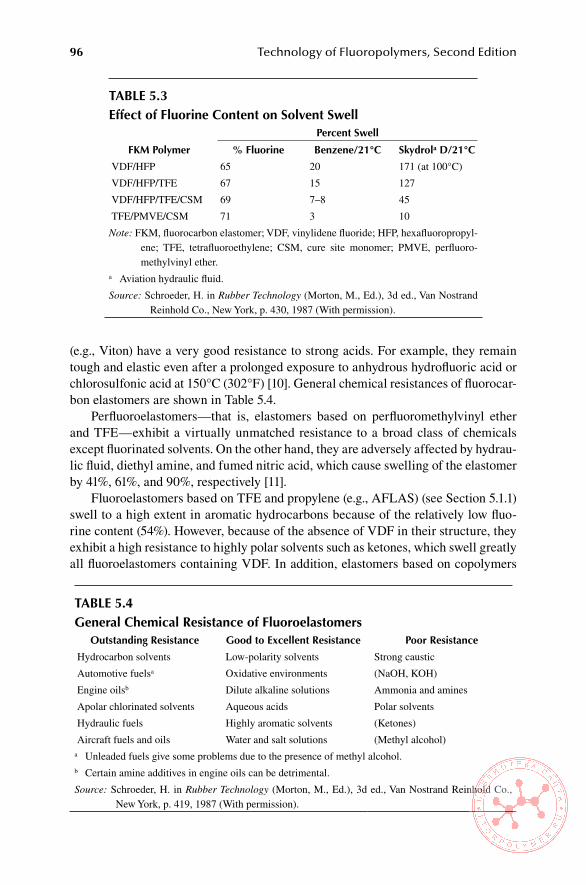
96 Technology of Fluoropolymers, Second Edition
(e.g., Viton) have a very good resistance to strong acids. For example, they remain tough and elastic even after a prolonged exposure to anhydrous hydrofluoric acid or chlorosulfonic acid at 150°C (302°F) [10]. General chemical resistances of fluorocar-bon elastomers are shown in Table 5.4.
Perfluoroelastomers—that is, elastomers based on perfluoromethylvinyl ether and TFE—exhibit a virtually unmatched resistance to a broad class of chemicals except fluorinated solvents. On the other hand, they are adversely affected by hydrau-lic fluid, diethyl amine, and fumed nitric acid, which cause swelling of the elastomer by 41%, 61%, and 90%, respectively [11].
Fluoroelastomers based on TFE and propylene (e.g., AFLAS) (see Section 5.1.1) swell to a high extent in aromatic hydrocarbons because of the relatively low fluo-rine content (54%). However, because of the absence of VDF in their structure, they exhibit a high resistance to highly polar solvents such as ketones, which swell greatly all fluoroelastomers containing VDF. In addition, elastomers based on copolymers
Table 5.3effect of Fluorine Content on solvent swell
Percent swell
FKM Polymer % Fluorine benzene/21°C skydrola D/21°C
VDF/HFP 65 20 171 (at 100°C)
VDF/HFP/TFE 67 15 127
VDF/HFP/TFE/CSM 69 7–8 45
TFE/PMVE/CSM 71 3 10
Note: FKM, fluorocarbon elastomer; VDF, vinylidene fluoride; HFP, hexafluoropropyl-ene; TFE, tetrafluoroethylene; CSM, cure site monomer; PMVE, perfluoro-methylvinyl ether.
a Aviation hydraulic fluid.
Source: Schroeder, H. in Rubber Technology (Morton, M., Ed.), 3d ed., Van Nostrand Reinhold Co., New York, p. 430, 1987 (With permission).
Table 5.4General Chemical Resistance of Fluoroelastomers
outstanding Resistance Good to excellent Resistance Poor Resistance
Hydrocarbon solvents Low-polarity solvents Strong caustic
Automotive fuelsa Oxidative environments (NaOH, KOH)
Engine oilsb Dilute alkaline solutions Ammonia and amines
Apolar chlorinated solvents Aqueous acids Polar solvents
Hydraulic fuels Highly aromatic solvents (Ketones)
Aircraft fuels and oils Water and salt solutions (Methyl alcohol)a Unleaded fuels give some problems due to the presence of methyl alcohol.b Certain amine additives in engine oils can be detrimental.
Source: Schroeder, H. in Rubber Technology (Morton, M., Ed.), 3d ed., Van Nostrand Reinhold Co., New York, p. 419, 1987 (With permission).
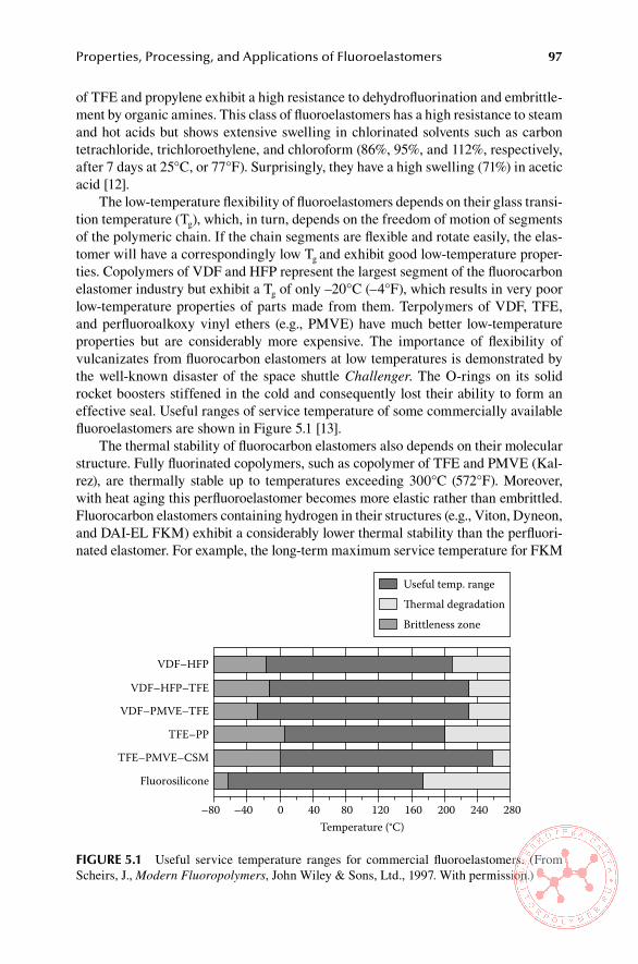
Properties, Processing, and Applications of Fluoroelastomers 97
of TFE and propylene exhibit a high resistance to dehydrofluorination and embrittle-ment by organic amines. This class of fluoroelastomers has a high resistance to steam and hot acids but shows extensive swelling in chlorinated solvents such as carbon tetrachloride, trichloroethylene, and chloroform (86%, 95%, and 112%, respectively, after 7 days at 25°C, or 77°F). Surprisingly, they have a high swelling (71%) in acetic acid [12].
The low-temperature flexibility of fluoroelastomers depends on their glass transi-tion temperature (Tg), which, in turn, depends on the freedom of motion of segments of the polymeric chain. If the chain segments are flexible and rotate easily, the elas-tomer will have a correspondingly low Tg and exhibit good low-temperature proper-ties. Copolymers of VDF and HFP represent the largest segment of the fluorocarbon elastomer industry but exhibit a Tg of only –20°C (–4°F), which results in very poor low-temperature properties of parts made from them. Terpolymers of VDF, TFE, and perfluoroalkoxy vinyl ethers (e.g., PMVE) have much better low-temperature properties but are considerably more expensive. The importance of flexibility of vulcanizates from fluorocarbon elastomers at low temperatures is demonstrated by the well-known disaster of the space shuttle Challenger. The O-rings on its solid rocket boosters stiffened in the cold and consequently lost their ability to form an effective seal. Useful ranges of service temperature of some commercially available fluoroelastomers are shown in Figure 5.1 [13].
The thermal stability of fluorocarbon elastomers also depends on their molecular structure. Fully fluorinated copolymers, such as copolymer of TFE and PMVE (Kal-rez), are thermally stable up to temperatures exceeding 300°C (572°F). Moreover, with heat aging this perfluoroelastomer becomes more elastic rather than embrittled. Fluorocarbon elastomers containing hydrogen in their structures (e.g., Viton, Dyneon, and DAI-EL FKM) exhibit a considerably lower thermal stability than the perfluori-nated elastomer. For example, the long-term maximum service temperature for FKM
VDF–HFP
VDF–HFP–TFE
VDF–PMVE–TFE
TFE–PP
TFE–PMVE–CSM
Fluorosilicone
–80 –40 0 40 80Temperature (°C)
120 160 200 240 280
Useful temp. rangeThermal degradationBrittleness zone
FiGURe 5.1 Useful service temperature ranges for commercial fluoroelastomers. (From Scheirs, J., Modern Fluoropolymers, John Wiley & Sons, Ltd., 1997. With permission.)

98 Technology of Fluoropolymers, Second Edition
is 215°C (419°F) compared with 315°C (599°F) for FFKM. In addition, it was shown that heating Viton A at 150°C (302°F) results in unsaturation and that metal oxides promote this dehydrofluorination at even lower temperatures [13]. Copolymers of VDF and CTFE (e.g., Kel-F) with upper long-term use temperature of about 200°C (392°F) are less heat resistant than copolymers of VDF and HFP [14]. Fluoroelasto-mers based on hydropentafluoropropylene (HPFP), such as Tecnoflon SL (copolymer of HPFP and VDF) and Tecnoflon T (terpolymer of VDF/HPFP/TFE), because of a lower fluorine content than that of their analogs with HFP, also exhibit lower thermal stability when compared with them [15,16].
Another factor affecting thermal stability of compounds based on fluorocarbon elastomers is the curing (cross-linking) system used. This subject is discussed at some length in the section on compounding.
Raw-gum fluorocarbon elastomers are transparent to translucent with molecu-lar weights from approximately 5000 (e.g., Viton LM with waxy consistency) to over 200,000. The most common range of molecular weights for commercial prod-ucts is 100,000 to 200,000. Polymers with molecular weights over 200,000 (e.g., Kel-F products) are very tough and difficult to process. Elastomers prepared with vinylidene fluoride as comonomer are soluble in certain ketones and esters, copoly-mers of TFE, and propylene in halogenated solvents; perfluorinated elastomers are practically insoluble [17].
5.1.3 cross-lInkIng chemIstry
Fluorocarbon elastomers based on vinylidene fluoride can be cross-linked by ionic mechanism. However, if the polymer has been prepared in the presence of a cure site monomer (CSM) it can be cross-linked (cured) by a free radical mechanism. More-over, many fluoroelastomers can be cross-linked by ionizing radiation (see Section 5.1.3.3).
5.1.3.1 Cross-linking by ionic Mechanism
Fluorocarbon elastomers based on VDF/HFP and VDF/HFP/TFE can be cured by bis-nucleophiles, such as bisphenols and diamines. The mechanism, proposed in [18], is outlined as follows:
1. Formation of –C(CF3)=CH– double bond by elimination of “tertiary” fluorine 2. Double bond shift catalyzed by fluoride ion and formation of –CH=CF–
double bond 3. Nucleophilic addition of the –CH=CF– double bond with: a. Allylic displacement of fluoride affording the new –C(CF3)=CH– double
bond b. Addition/fluoride elimination from the same double bond
The detailed description is in Figure 5.2 [19], where the bis-nucleophile Nu–R–Nu represents a bisphenol or diamine cross-linking agent.
The general disadvantage of curing fluoroelastomers by ionic mechanism is that dehydrofluorination required for this reaction produces considerably more double
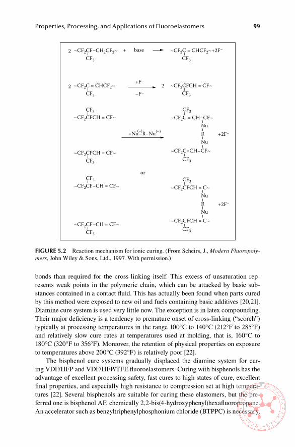
Properties, Processing, and Applications of Fluoroelastomers 99
bonds than required for the cross-linking itself. This excess of unsaturation rep-resents weak points in the polymeric chain, which can be attacked by basic sub-stances contained in a contact fluid. This has actually been found when parts cured by this method were exposed to new oil and fuels containing basic additives [20,21]. Diamine cure system is used very little now. The exception is in latex compounding. Their major deficiency is a tendency to premature onset of cross-linking (“scorch”) typically at processing temperatures in the range 100°C to 140°C (212°F to 285°F) and relatively slow cure rates at temperatures used at molding, that is, 160°C to 180°C (320°F to 356°F). Moreover, the retention of physical properties on exposure to temperatures above 200°C (392°F) is relatively poor [22].
The bisphenol cure systems gradually displaced the diamine system for cur-ing VDF/HFP and VDF/HFP/TFE fluoroelastomers. Curing with bisphenols has the advantage of excellent processing safety, fast cures to high states of cure, excellent final properties, and especially high resistance to compression set at high tempera-tures [22]. Several bisphenols are suitable for curing these elastomers, but the pre-ferred one is bisphenol AF, chemically 2,2-bis(4-hydroxyphenyl)hexafluoropropane. An accelerator such as benzyltriphenylphosphonium chloride (BTPPC) is necessary,
~CF2CF–CH2CF2~ ~CF2C = CHCF2~+2F–
~CF2C = CHCF2~
~CF2CFCH = CF~
CF3
CF3
CF3
~CF2CF–CH = CF~ CF3
~CF2CFCH = CF~
CF3
~CF2CF–CH = CF~
CF3 CF3
~CF2CFCH = CF~CF3
+2F–
+2F–
~CF2C = CH–CF~
~CF2C=CH–CF~CF3
Nu
NuR
CF3
~CF2CFCH = C~
~CF2CFCH = C~CF3
Nu
NuR
CF3
+ base
+F–2
2
2–F–
or
+Nu–R–Nu(–)(–)
FiGURe 5.2 Reaction mechanism for ionic curing. (From Scheirs, J., Modern Fluoropoly-mers, John Wiley & Sons, Ltd., 1997. With permission.)

100 Technology of Fluoropolymers, Second Edition
along with inorganic bases, such as calcium hydroxide and magnesium hydroxide with small particle sizes [23]. Typical amounts are 2 phr (parts per hundred parts of rubber) of bisphenol AF, 0.5–0.6 phr of accelerator, 3 phr of MgO, and 6 phr of Ca(OH)2.
5.1.3.2 Cross-linking by Free Radical Mechanism (Peroxide Cure)
The reaction is activated by an organic peroxide that decomposes thermally during the cure. The fluoroelastomer has to contain reaction sites to produce a sufficiently high cross-link density. Bromine-containing fluoroelastomers form a stable network in the presence of peroxide. However, bromine-based fluoroelastomers were found to cause processing problems, mainly mold fouling. Iodine-based fluoroelastomers were found to be much better since they produce much less mold fouling and are suitable for more sophisticated molding techniques, such as injection molding [24]. They also exhibit excellent sealing properties; however, their thermal stability is lower than that of bromine-based fluoroelastomers [25]. The use of peroxides for cross-linking requires the addition of a coagent (radical trap), for example, triallyl isocyanurate (TAIC) or triallyl cyanurate (TAC).
Perfluoroelastomers (FFKM) contain a CSM that is essential for their cross-linking. Examples of CSMs are as follows:
Perfluoro(8-cyano-5-methyl-3,6-dioxa-1-octene) (8-CNVE) [26]•Perfluoro(2-phenoxypropyl vinyl ether)•VDF•Bromine- or iodine- or nitrile-containing monomers•
Each of these has a specific curing behavior and provides vulcanizates with dif-ferent characteristics. To attain sufficient heat resistance, the compounds require long post-cures at high temperatures, such as 288°C (550°F), in some cases under nitrogen [27]. Details about different systems are in [27].
5.1.3.3 Cross-linking by ionizing Radiation
5.1.3.3.1 Cross-Linking of FKM Type of ElastomersFluorocarbon elastomers with ASTM designation FKM are predominantly copo-lymers or terpolymers of different fluorinated or perfluorinated monomers with vinylidene fluoride, as pointed out earlier. The presence of vinylidene fluoride in their molecules is responsible for their propensity to cross-link by responding to the ionizing radiation (EB and γ-rays). Here again, the final result depends on the ratio of cross-linking to chain scission. Prorads, such as TAC, TAIC, trimethylolpropane trimethacrylate (TMPTM), trimethylolpropane triacrylate (TMPTA) and N, N’-(m-phenylene) bismaleimide (MPBM), reduce the damage to the elastomeric chain by the radiation [28]. It appears that each fluorocarbon elastomer has the best cross-link yield with a specific prorad. In general, optimized compounds from fluorocar-bon elastomers irradiated at optimum conditions attain considerably better thermal stability and mechanical properties than chemical curing systems [29–31]. Typical
Properties, Processing, and Applications of Fluoroelastomers 101
radiation dose for a sufficient cross-linking of most fluorocarbon elastomers is on the range 10 to 100 kGy.
5.1.3.3.2 Cross-Linking of FFKM Type of ElastomersPerfluoroelastomers (ASTM designation FFKM) are essentially copolymers of two perfluorinated monomers, TFE and PMVE with a CSM, which is essential for cross-linking. Perfluoroelastomers can be cured by ionizing radiation without any addi-tives. The advantage of radiation cured FFKM is the absence of any additives, so that the product is very pure. The disadvantage is the relatively low upper-use tem-perature of the cured material, typically 150°C, which limits the material to special sealing applications only [32].
5.1.4 formulatIon of comPounds from fluorocarbon elastomers
When compounding fluorocarbon elastomers, the basic principles are the same as for other elastomers. The selection of the elastomer grade and of the remaining com-pounding ingredients depends on required physical and chemical properties of the vulcanizate (cured compound) as well as on the desired behavior of the compound during processing and curing.
A typical FKM compound usually contains the following ingredients: one or more fillers, an acid scavenger, and a curing system (cross-linker). Inorganic or organic col-orants are used for colored compounds. The development of a compound requires a great deal of experience and understanding of the chemistry involved and of the inter-actions among the individual ingredients. However, the compounding of fluorocarbon elastomers is relatively simpler than that of other types of elastomers [33].
5.1.4.1 Fillers
The type and amount of filler affect not only the final properties of the vulcanizate but also the processing behavior of the compound. Since the compounds stiffen very soon after mixing, only relatively small amounts of fillers, typically 10 to 30 phr, can be used [34].
Various carbon blacks are used for black compounds. Medium thermal black (N990) is the most widely used grade, because it offers the best compromise between physical properties and cost. More reinforcing grades of carbon blacks, such as N774 or N750, produce a higher hardness and better physical properties at the expense of somewhat higher compression set and cost. Lowest compression set values are obtained with Austin black [34].
White (silica) fillers, often surface treated, are sometimes used to improve flow, moisture resistance, and tensile properties [35–37].
Fillers commonly used in fluorocarbon elastomers are listed in Table 5.5 [38].
5.1.4.2 acid acceptor systems
Acid acceptors serve the purpose of neutralizing the hydrogen fluoride generated during the cure or on prolonged aging at high temperatures. The compounds used for that purpose are listed in Table 5.6. Low-activity magnesium oxide is used in diamine cures and not in bisphenol cures. High-activity magnesium oxide is used in
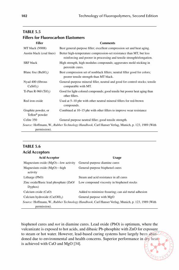
102 Technology of Fluoropolymers, Second Edition
bisphenol cures and not in diamine cures. Lead oxide (PbO) is optimum, where the vulcanizate is exposed to hot acids, and dibasic Pb-phosphite with ZnO for exposure to steam or hot water. However, lead-based curing systems have largely been aban-doned due to environmental and health concerns. Superior performance in dry heat is achieved with CaO and MgO [34].
Table 5.5Fillers for Fluorocarbon elastomers
Filler Comments
MT black (N908) Best general-purpose filler; excellent compression set and heat aging.
Austin black (coal fines) Better high-temperature compression-set resistance than MT, but less reinforcing and poorer in processing and tensile strength/elongation.
SRF black High strength, high modulus compounds; aggravates mold sticking in peroxide cures.
Blanc fixe (BaSO4) Best compression set of nonblack fillers; neutral filler good for colors; poorer tensile strength than MT black.
Nyad 400 (fibrous CaSiO3)
General-purpose mineral filler, neutral and good for control stocks; tensile comparable with MT.
Ti-Pure R-960 (TiO2) Good for light-colored compounds; good tensile but poorer heat aging than other fillers.
Red iron oxide Used at 5–10 phr with other neutral mineral fillers for red-brown compounds.
Graphite powder, or Teflon® powder
Combined at 10–15 phr with other fillers to improve wear resistance
Celite 350 General purpose neutral filler; good tensile strength.
Source: Hoffmann, W., Rubber Technology Handbook, Carl Hanser Verlag, Munich, p. 123, 1989 (With permission).
Table 5.6acid acceptors
acid acceptor Usage
Magnesium oxide (MgO)—low activity General-purpose diamine cures
Magnesium oxide (MgO)—high activity
General-purpose bisphenol cures
Litharge (PbO) Steam and acid resistance in all cures
Zinc oxide/Basic lead phosphate (ZnO/Dyphos)
Low compound viscosity in bisphenol stocks
Calcium oxide (CaO) Added to minimize fissuring; can aid metal adhesion
Calcium hydroxide (Ca(OH)2) General purpose with MgO
Source: Hoffmann, W., Rubber Technology Handbook, Carl Hanser Verlag, Munich, p. 123, 1989 (With permission).

Properties, Processing, and Applications of Fluoroelastomers 103
5.1.4.3 Curatives
Generally, as discussed previously, the mechanism involved in the cross-linking of fluo-roelastomers is the removal of hydrogen fluoride to generate a cure site that then reacts with diamine [39], bisphenol [40], or organic peroxides [41] that promote a radical cure by hydrogen or bromine extraction. Preferred amines have been blocked diamines such as hexamethylene carbamate (Diak No. 1) or bis(cinnamylidene) hexamethylene diamine (Diak No. 3). Preferred phenols are hydroquinone and the bisphenols such as 4,4′-isopro-pylidene bisphenol or the corresponding hexafluoro-derivative bisphenol AF.
The nucleophilic curing system is most common and is used in about 80% of all applications. It is based on the cross-linker (bisphenol AF) and accelerator (phase transfer catalyst, such as phosphonium or amino-phosphonium salt). Both diaminic and bisphenol type cure systems are permitted by U.S. Food and Drug Administra-tion (FDA) regulations governing rubber articles in contact with food. The diaminic curing system is also used in some coating and extrusion applications [42].
Peroxidic cure systems are applicable only to fluorocarbon elastomers with cure sites that can generate new stable bonds. Although peroxide-cured fluorocarbon elas-tomers have inferior heat resistance and compression set, compared with bisphenol cured types they develop excellent physical properties with little or no postcuring. Peroxide cured fluoroelastomers also provide superior resistance to steam, acids, and other aqueous solvents because they do not require metal oxide activators used in bisphenol cure systems. Their difficult processing was an obstacle to their wider use for years, but recent improvements in chemistry and polymerization are offering more opportunities for this class of elastomers [42].
Solid fluorocarbon elastomers are commercially available as pure gum polymers or precompounded grades with bisphenol type curing system included. Some precom-pounded stocks include processing aids, adhesion promoters, or other application-specific additives. The relative strengths and weaknesses of commonly used curing systems are listed in Table 5.7.
Precompounded grades are optimized by the supplier to provide the best com-bination of accelerator and cross-linker for a given application [43]. Then, the final compounding consists of only the addition of fillers, activators, and other ingredients needed to achieve the required physical properties and processing characteristics.
Although development of a formulation for a specific product and process requires a great deal of knowledge and experience, there are some basic rules typical of FKM compounding. The levels of acid acceptor (MgO) and activator (Ca(OH)2) in the bis-phenol cure system strongly affect not only the cross-link network as reflected by the physical properties of the material but also the behavior of the compound during vulca-nization. Therefore, the curing system must be optimized to achieve the best balance of properties. Examples of formulations for different curing systems are in Table 5.8.
5.1.4.4 Plasticizers and Processing aids
Processing behavior of fluoroelastomers can be improved by the addition of small amounts of plasticizers and processing aids. High-molecular-weight hydrocarbon esters, such as dioctyl phtalate (DOP) and pentaerythritol stearate, are effective plas-ticizers in fluoroelastomer compounds. Lower-molecular-weight esters also soften

104 Technology of Fluoropolymers, Second Edition
Table 5.7Curing systems for Fluorocarbon elastomersCharacteristics Diamine bisphenol Peroxide
Scorch safety P–F G–E G–E
Balance of fast cure and scorch safety P E E
Mold release G E F
Ability to single-pass Banbury mix No or risky Yes Yes
Adhesion to metal E G G
Tensile strength G–E F–E G–E
Compression-set resistance F E G
Steam and acid resistance F G E
Note: E, excellent; G, good; F, fair; P, poor.
Source: Hoffmann, W., Rubber Technology Handbook, Carl Hanser Verlag, Munich, p. 123, 1989 (With permission).
Table 5.8examples of Formulations for Different Curing systems
ingredient
Curing system (phr)
Diamine bisphenol Peroxide
FKM 100 100 —
FKM with CSM — — 100
MgO (low activity) 15 — —
MgO (high activity) — 3–6 —
Inactive fillers 10–50 10–50 10–50
Diamine 1–3 — —
Bisphenol — 1–3 —
Triphenylbenzyl phosphonium chloridea — 3–6 —
Ca(OH)2 — 3–6 —
PbO and Pb-phosphite — — 3–6
TAC or TAIC — — 1–3
Peroxideb — — 2–6
Note: FKM, fluorocarbon elastomer; CSM, cure site monomer; TAC, triallyl cyanurate; TAIC, trial-lyl isocyanurate.
a Accelerator.b 2,5-dimethyl-2,5-di(t-butylperoxy)hexane.
Source: Schroeder, H. in Rubber Technology (Morton, M., Ed.), 3d ed., Van Nostrand Reinhold Co., New York, p. 427, 1987 (With permission).

Properties, Processing, and Applications of Fluoroelastomers 105
such compounds, but they reduce their high-temperature stability because they are less stable than fluorocarbons and highly volatile at the usual service temperatures. Carnauba wax, low-molecular-weight polyethylene (e.g., AC-617), and sulfones act as good processing aids. These additives ensure improved calendering, smoother extru-sion, and an improved flow in molds. Low-molecular-weight polyethylene should not be used in compounds with peroxide-curing systems because it aggravates mold sticking. Other commercially available processing aids are low-viscosity fluorocar-bon elastomers that improve processing without having an adverse effect on physical properties of the vulcanizate [44].
5.1.4.5 examples of Formulations
Compounds for Compression Molded Seals [45]
ingredient amounts (Parts by Weight)
Compound i Compound ii
FKM 100 100
N990 (medium thermal) carbon black 15 15
Magnesia 20 —
Calcium oxide —
Diak #3 3 —
HMDA-C — 1.2
Total 138.0 136.2a Hexamethylene diamine carbamate (curing agent).
scorch
Mooney Scorch, MS at 250°F, min 25+ 44
Minimum reading, units 44 50
Physical Properties: Press-Cured 30 Min at 300°F (149°C); Postcured in oven 24 h at 400°F (204°C)
original Physical Properties
Tensile strength, psi (MPa) 2640 (18.2) 1750 (12.0)
Elongation at break, % 305 195
Hardness, Durometer A 65 73
aged in oven 16 h at 400°F (204°C)
Tensile strength, psi (MPa) 1500 (10.3) 1460 (10.1)
Elongation at break, % 160 170
Hardness, Durometer A 79 80
aged in oven 2 days at 600°F (316°C)
Tensile strength, psi (MPa) Brittle 1160 (8.0)
Elongation at break, % — —
Hardness, durometer A 98 87
Compression set (asTM D395, Method b), 22 h at 450°F (232°C)
Set, % 47 38

106 Technology of Fluoropolymers, Second Edition
Compounds for Extruded Goods [46]
ingredient
amounts (Parts by Weight)
Compound i Compound ii
FKM 100 100
N990 (medium thermal) carbon black 35 15
N326 (high abrasion furnace) carbon black — 5
N762 (semi-reinforcing furnace) carbon black — 7
Magnesium oxide 3 9
Calcium hydroxide 6 —
Carnauba wax 1 1
Bisphenol AF 1.9 1.9
TPBPCa (accelerator) 0.45 0.45
Total 147.35 139.35
Physical Properties: Press-Cured 45 Min at 320°F (160°C)
Tensile strength, psi (MPa) 1102 (7.6) 1798 (12.4)
Elongation at break, % 280 330
Hardness, Durometer A 65 73a Triphenyl benzyl phosphonium chloride
Compound for Peroxide Cured Seals [46]
ingredient amount (Parts by Weight)
FKM (high fluorine elastomer, containing PMVE) 100
Litharge 3
N990 (medium thermal) carbon black 30
Hard wax 1
Fatty acid amide 0.50
Stearic acid 0.25
TAIC (coagent) 3.00
50% DBPH (peroxide) a 3.00
Total 140.75
Physical Properties (Fully Cured)
Hardness, Durometer A 75–80a 2,5-dimethyl-2,5 di(t-butylperoxy)hexane.
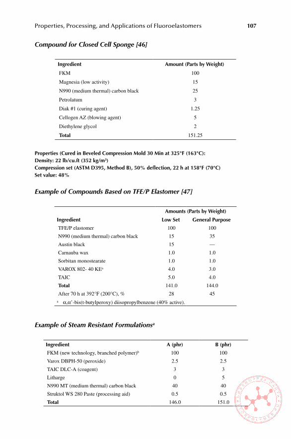
Properties, Processing, and Applications of Fluoroelastomers 107
Compound for Closed Cell Sponge [46]
ingredient amount (Parts by Weight)
FKM 100
Magnesia (low activity) 15
N990 (medium thermal) carbon black 25
Petrolatum 3
Diak #1 (curing agent) 1.25
Cellogen AZ (blowing agent) 5
Diethylene glycol 2
Total 151.25
Properties (Cured in beveled Compression Mold 30 Min at 325°F (163°C):Density: 22 lb/cu.ft (352 kg/m3)Compression set (asTM D395, Method b), 50% deflection, 22 h at 158°F (70°C)set value: 48%
Example of Compounds Based on TFE/P Elastomer [47]
ingredient
amounts (Parts by Weight)
low set General Purpose
TFE/P elastomer 100 100
N990 (medium thermal) carbon black 15 35
Austin black 15 —
Carnauba wax 1.0 1.0
Sorbitan monostearate 1.0 1.0
VAROX 802- 40 KEa 4.0 3.0
TAIC 5.0 4.0
Total 141.0 144.0
After 70 h at 392°F (200°C), % 28 45a α,α’-bis(t-butylperoxy) diisopropylbenzene (40% active).
Example of Steam Resistant Formulationsa
ingredient a (phr) b (phr)
FKM (new technology, branched polymer)b 100 100
Varox DBPH-50 (peroxide) 2.5 2.5
TAIC DLC-A (coagent) 3 3
Litharge 0 5
N990 MT (medium thermal) carbon black 40 40
Struktol WS 280 Paste (processing aid) 0.5 0.5
Total 146.0 151.0

108 Technology of Fluoropolymers, Second Edition
Properties—Measured on specimens Cured 10h at 177°C (350°F), Postcured 4 h at 230°C (496°F)
Hardness, Durometer A 83 85
Tensile strength, MPa 19.3 19.4
Elongation at break, % 223 225
Modulus at 100% elongation, MPa 7.3 8.0
Fluid Resistance (asTM D471), Water, 70 h at 200°C; o-Rings
Change in Durometer A, points –12 –12
Change in tensile strength, % –42 –45
Change in elongation at break, % 7 37
Change in modulus @100% elongation, % –37 –44
Volume change, % 15 7
Fluid Resistance (asTM D471), steam, 22 h at 200°C; o-Rings
Change in Durometer A, points –9 –9
Change in tensile strength, % –54 –53
Change in elongation at break, % 38 71
Change in modulus at 100% elongation, % –32 –38
Volume change, % 4 2a Tecnoflon® Guide to Fluoroelastomers, Solvay Solexis, Inc. 2005.b For example, Tecnoflon P459.
5.1.5 mIxIng and ProcessIng of comPounds from fluorocarbon elastomers
5.1.5.1 Mixing
Compounds from solid fluorocarbon elastomers are mixed on the equipment common in the rubber industry. However, the mixing procedures typical for standard types of elastomers are often modified to be suitable for mixing fluorocarbon elastomers.
Open-mill mixing is used mainly for special compounds prepared in small vol-umes. The advantages of mill mixing are its simplicity, the fact that the operator can control the temperature of the material on the rolls, and an easy cleanup. However, mill mixing, especially on production scale, is rather difficult, especially for a num-ber of gum fluoroelastomers. Polymers with narrow molecular weight distribution and low levels of ionic end-group levels may not have adequate cohesive strength to form a smooth band without holes on the mill rolls. Very high-molecular weight fluo-roelastomers undergo significant breakdown during initial passes through a tight nip of a cold mill, which leads to reduction of physical properties of the resulting vulca-nizate. On the other hand, bimodal blends (formed by latex mixing before isolation) have excellent milling characteristics with negligible breakdown of high-molecular weight fraction [48]. High-viscosity elastomers with considerable long-chain branch-ing and gel content may also break down during milling, possibly improving subse-quent processing characteristics [49].
Properties, Processing, and Applications of Fluoroelastomers 109
Mixing in internal mixers is considerably more productive; however, because of the high intensity of mixing in an enclosed chamber, there is relatively high risk of premature onset of cross-linking (i.e., scorch). Compounds tending to scorch are most commonly mixed in two steps (i.e., passes). In the first pass, the elastomer is mixed with processing aids, fillers, pigments, activators, and acid acceptors. The cross-linking agents are almost always added in the second pass.
5.1.5.2 Processing
Mixed compounds are almost always transformed into products with required shapes and dimensions. There are several methods to accomplish this. Tubes, solid round profiles, and profiles with irregular, often complex shapes, are prepared by extrusion. Sheets, slabs, and rubber-coated fabrics are made mainly by calendering.
5.1.5.2.1 CalenderingCalendering, as mentioned earlier, is used to produce sheets, slabs, and certain types of coated fabrics. The grades most suitable for calendering are those with low viscos-ity. Processing aids are necessary to improve surface smoothness and a good release of sheets from the rolls.
Mixed stocks should be used promptly or stored at temperatures below 18°C (65°F) to prevent scorching, and great care should be taken to exclude moisture. Typical roll temperatures for calendering recommended for Viton E-60C or related Dyneon types are as follows [50]:
Top roll: 85 ± 3.5°C (185 ± 5°F)Middle roll: 74 ± 3.5°C (165 ± 5°F)Bottom roll: Cool (ambient temperature)Speed: 7 to 10 m/min or 7.6 to 11 yd/min
The setting of roll temperatures depends on the cure systems used. Typically, stocks with diamine (e.g., Diak No. 3) are calendered at temperatures of top and middle rolls set 15°C to 20°C (27°F to 36°F) lower than stocks with bisphenol and peroxide [51].
5.1.5.2.2 ExtrusionExtrusion of tubes, hose, and profiles is done on standard extruders for rubber. The usual temperature pattern is a gradual increase of temperature from the feed zone to the die. The die temperature is typically 100°C (212°F), and the screw temperature is approximately the same as the temperature of the feed zone [44]. Processing aids are almost always required to improve the surface appearance and to increase the extrusion rate. Extrusion represents only a small proportion (about 10%) of the total consumption of fluorocarbon elastomers [52].Cold feed extruders typically used for extrusion of rubber stocks are also suitable for the extrusion of fluorocarbon elasto-mers. Extrusion should be carried out at temperatures below 120°C (250°F) to avoid scorch. In most cases a breaker plate and screen pack are used to generate backpres-sure on the screw and to remove foreign particles from the stock. A straight head is used for the extrusion of profiles or tubing, whereas a cross-head die is used for
110 Technology of Fluoropolymers, Second Edition
coating wires or extrusion of veneer on a mandrel as the inner layer of fuel hose. Ram extruders, such as Barwell precision preformer [53], are used widely for production of blanks for compression molding. Typical ram pressures are up to 35 MPa (5070 psi). Various dies (e.g., dies for rods, tubing, and strips) are available for extrudate diameters up to 190 mm (7.5 in.). Barwell preformers are useful for processing high-cost specialty fluoroelastomers used in limited volumes of precision molded parts [54].
5.1.5.2.3 Compression MoldingCompression molding has several advantages for fabrication of fluoroelastomer parts. Loss of expensive material may be minimized by careful control of preform size. The process is advantageous for relatively small production volumes of parts of any size. Compression molding works best with stocks of medium to high viscos-ity. The disadvantage of compression molding is a high labor cost since the process requires operator attention to loading preforms, closing and opening molds, and removing cured parts.
5.1.5.2.4 Transfer MoldingWhen compared with compression molding, transfer molding provides better prod-uct consistency, shorter cycle times, and better bonding of rubber to metal [55]. How-ever, considerable amount of material is lost as scrap in the transfer pad, sprues, and flash. The basic three-plate multiple cavity mold is more complex and expensive than a comparable compression mold but is suited better for intricate parts or securing inserts [56].
5.1.5.2.5 Injection MoldingInjection molding is the most advanced method of molding rubber products [55]. The widely used equipment is reciprocating screw machine. The compound is usually fed to the screw as a continuous strip or as pellets from a hopper. As the stock accumu-lates at the front of the screw, the screw is forced backward a specified distance in preparation for the shot. Then the rotation of the screw is stopped, and it is pushed forward to inject the specified amount into the closed mold. While the rubber cures, the screw is initially held in the injection position to maintain the predetermined pressure to consolidate the stock. Then after a preset time, the screw rotates again to refill the barrel. Then the mold is opened for the removal of the cured part and subsequently closed for the next shot. Ram or piston injection molding machines are also used for rubber processing. These are somewhat similar to the transfer mold-ing process. Of all the molding processes, injection molding provides the maximum product consistency, shortest cycle times, and minimum flash. The main disadvan-tage is the highest investment cost of the machine, molds, and auxiliary equipment. The process is most suitable for high volume production. Fluoroelastomers with low viscosity (less than 30 as measured on the Mooney viscometer) at 121°C are required for injection molding, The use of one or more process aids is essential to enhance mold flow during injection and easy release of parts from the mold after curing.
Ram and piston injection molding units are used in the rubber industry [57]. The rubber stock is fed to a heated cylinder, which is heated to the required temperature and from there is forced by a hydraulic ram through a nozzle, mold runners, and

Properties, Processing, and Applications of Fluoroelastomers 111
restrictive gates to the mold. Ram injection molding machines are somewhat lower in cost than the reciprocating screw unit but are less efficient, especially for high-viscosity stocks. Typical process conditions for injection molding of fluoroelasto-mers are in Table 5.9.
Most molds for injection molding are unique in design, which depends on appli-cation, fluoroelastomer compound, and feed system (hot or cold runners). Standard systems are distinguished as two plate, three plate, or stack molds [58].
5.1.6 solutIon and latex coatIng
Certain substrates (woven and nonwoven fabrics, foils, and films) are coated by dip-ping, spreading, or spraying with fluoroelastomers in liquid form. The older method using a solution of fluoroelastomers in volatile solvents (e.g., methyl ethyl ketone, toluene) is gradually being replaced by the use of water-based latexes. Fluoroelas-tomer latexes can also be used for chemically resistant and heat-resistant coatings. Some fluoropolymer producers offer latex in limited quantities to processors skilled
Table 5.9Process Conditions for injection Molding of FluoroelastomersMachine Ram Type screw Type
Temperature settings, °C
Barrel
Feed zone 80–90 25–40
Middle zone 80–90 70–80
Front zone 80–90 80–100
Nozzle
Nozzle extrudate 165–170 165–170
Mold 205–220 205–220
Stock in mold 165–170 165–170
Pressure Settings, MPa
Injection 14–115 14–115
Hold pressure — 1/2 injection pressure
Back pressure — 0.3–1
Clamping pressure Maximum Maximum
Screw speed, rpm — 40–60
Time setting, seconds (for thin parts)
Total cycle 58–75 43–60
Clamp 48–65 33–50
Injection 3–5 3–5
Hold — 10–15
Cure (includes hold) 45–60 30–45
Open-ejection of parts 10 10
Source: Processing Guide Viton® Fluoroelastomer, Technical Information Bulletin VTE-H90171-00-A0703, DuPont Dow Elastomers, 2003 (With permission).
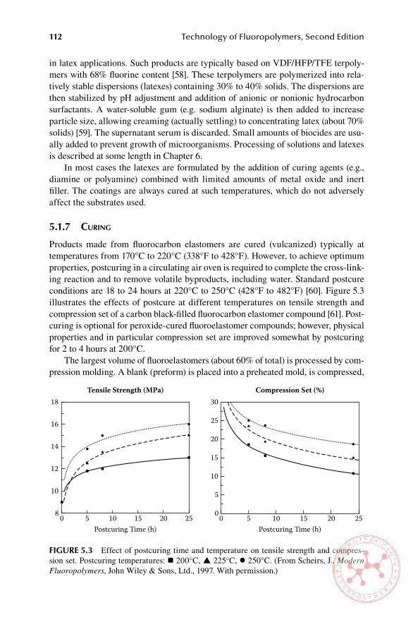
112 Technology of Fluoropolymers, Second Edition
in latex applications. Such products are typically based on VDF/HFP/TFE terpoly-mers with 68% fluorine content [58]. These terpolymers are polymerized into rela-tively stable dispersions (latexes) containing 30% to 40% solids. The dispersions are then stabilized by pH adjustment and addition of anionic or nonionic hydrocarbon surfactants. A water-soluble gum (e.g. sodium alginate) is then added to increase particle size, allowing creaming (actually settling) to concentrating latex (about 70% solids) [59]. The supernatant serum is discarded. Small amounts of biocides are usu-ally added to prevent growth of microorganisms. Processing of solutions and latexes is described at some length in Chapter 6.
In most cases the latexes are formulated by the addition of curing agents (e.g., diamine or polyamine) combined with limited amounts of metal oxide and inert filler. The coatings are always cured at such temperatures, which do not adversely affect the substrates used.
5.1.7 curIng
Products made from fluorocarbon elastomers are cured (vulcanized) typically at temperatures from 170°C to 220°C (338°F to 428°F). However, to achieve optimum properties, postcuring in a circulating air oven is required to complete the cross-link-ing reaction and to remove volatile byproducts, including water. Standard postcure conditions are 18 to 24 hours at 220°C to 250°C (428°F to 482°F) [60]. Figure 5.3 illustrates the effects of postcure at different temperatures on tensile strength and compression set of a carbon black-filled fluorocarbon elastomer compound [61]. Post-curing is optional for peroxide-cured fluoroelastomer compounds; however, physical properties and in particular compression set are improved somewhat by postcuring for 2 to 4 hours at 200°C.
The largest volume of fluoroelastomers (about 60% of total) is processed by com-pression molding. A blank (preform) is placed into a preheated mold, is compressed,
Tensile Strength (MPa)18
16
14
12
10
8 0 5 10Postcuring Time (h)
15 20 25Postcuring Time (h)
Compression Set (%)30
25
20
15
10
5
00 5 10 15 20 25
FiGURe 5.3 Effect of postcuring time and temperature on tensile strength and compres-sion set. Postcuring temperatures: 200°C, 225°C, 250°C. (From Scheirs, J., Modern Fluoropolymers, John Wiley & Sons, Ltd., 1997. With permission.)
------------ .. �················
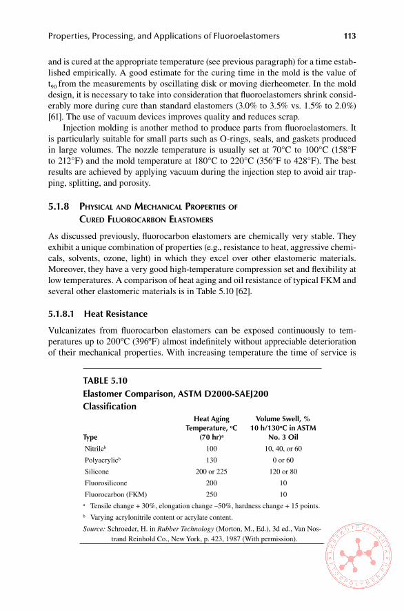
Properties, Processing, and Applications of Fluoroelastomers 113
and is cured at the appropriate temperature (see previous paragraph) for a time estab-lished empirically. A good estimate for the curing time in the mold is the value of t90 from the measurements by oscillating disk or moving dierheometer. In the mold design, it is necessary to take into consideration that fluoroelastomers shrink consid-erably more during cure than standard elastomers (3.0% to 3.5% vs. 1.5% to 2.0%) [61]. The use of vacuum devices improves quality and reduces scrap.
Injection molding is another method to produce parts from fluoroelastomers. It is particularly suitable for small parts such as O-rings, seals, and gaskets produced in large volumes. The nozzle temperature is usually set at 70°C to 100°C (158°F to 212°F) and the mold temperature at 180°C to 220°C (356°F to 428°F). The best results are achieved by applying vacuum during the injection step to avoid air trap-ping, splitting, and porosity.
5.1.8 PhysIcal and mechanIcal ProPertIes of cured fluorocarbon elastomers
As discussed previously, fluorocarbon elastomers are chemically very stable. They exhibit a unique combination of properties (e.g., resistance to heat, aggressive chemi-cals, solvents, ozone, light) in which they excel over other elastomeric materials. Moreover, they have a very good high-temperature compression set and flexibility at low temperatures. A comparison of heat aging and oil resistance of typical FKM and several other elastomeric materials is in Table 5.10 [62].
5.1.8.1 heat Resistance
Vulcanizates from fluorocarbon elastomers can be exposed continuously to tem-peratures up to 200ºC (396ºF) almost indefinitely without appreciable deterioration of their mechanical properties. With increasing temperature the time of service is
Table 5.10elastomer Comparison, asTM D2000-saeJ200 Classification
Type
heat aging Temperature, oC
(70 hr)a
volume swell, %10 h/130oC in asTM
no. 3 oil
Nitrileb 100 10, 40, or 60
Polyacrylicb 130 0 or 60
Silicone 200 or 225 120 or 80
Fluorosilicone 200 10
Fluorocarbon (FKM) 250 10a Tensile change + 30%, elongation change –50%, hardness change + 15 points.b Varying acrylonitrile content or acrylate content.
Source: Schroeder, H. in Rubber Technology (Morton, M., Ed.), 3d ed., Van Nos-trand Reinhold Co., New York, p. 423, 1987 (With permission).

114 Technology of Fluoropolymers, Second Edition
reduced as illustrated in Table 5.11 [63]. An example of heat resistance of two com-pounds is shown in Table 5.12 [64].
5.1.8.2 Compression set Resistance
The largest volume of fluorocarbon elastomers is used for O-rings and seals. In these applications, compression set is the most important property affecting the perfor-mance of the seal. The lowest values of compression set are achieved when using phosphonium chloride accelerator system with bisphenol AF or other phenol cures with certain grades of FKM (e.g., Viton E-60C or Dyneon 2170). Peroxide cures give generally poorer compression set than bisphenol cures. Coagents for the peroxide curing system have an effect on compression set: TAIC gives, for instance, a lower compression set than TAC [65].
5.1.8.3 low-Temperature Flexibility
Most commercial fluorocarbon elastomers have brittle points between –25°C (–13°F) and –40°C (–40°F). The low-temperature flexibility depends on the chemical struc-ture of the polymer and cannot be improved markedly by compounding. The use of plasticizers may help somewhat, but at a cost of reduced heat stability and worsened aging. Peroxide-curable polymers may be blended with fluorosilicones, but such blends exhibit considerably lower high-temperature stability and solvent resistance and are considerably more expensive than the pure fluorocarbon polymer. Viton GLT is a product with a low brittle point of –51°C (–59°F) [48]. Tecnoflon for containing a stable fluorinated amide plasticizer reportedly exhibits improved low-temperature hardness, brittle point, and compression set without sacrificing physical properties [66]. Low-temperature characteristics of selected fluorocarbon elastomers are listed in Table 5.13 [9].
5.1.8.4 Resistance to automotive Fuels
The use of aromatic compounds in automotive fuels, higher under-the-hood tem-peratures, combined with automotive regulations, presents a challenge for the rub-ber parts (e.g., hose, seals, diaphragms) used in vehicles. Traditional elastomers do not have high enough resistance to meet all these requirements, but fluorocarbon
Table 5.11service life versus Temperaturelimit, hours of service Temperature, °C (°F)
> 3000 230 (356)
1000 260 (410)
240 290 (464)
48 315 (509)
Source: Schroeder, H. in Rubber Technology (Morton, M., Ed.), 3d ed., Van Nos-trand Reinhold Co., New York, p. 427, 1987 (With permission).
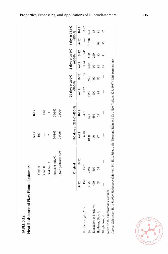
Properties, Processing, and Applications of Fluoroelastomers 115
Tab
le 5
.12
hea
t R
esis
tanc
e of
FK
M F
luor
oela
stom
ers
a-1
2b
-12
Vito
n A
100
—
Vito
n B
—10
0
Dia
k N
o. 3
23
Pres
sure
min
/oC
30/1
6330
/163
Ove
n po
stcu
re: h
r/o C
24/2
0424
/204
ori
gina
l10
0 da
ys a
t 23
2o C (
450o F
)20
day
s at
260
o C
(500
o F)
2 da
ys a
t 31
6o C
(600
o F)
1 da
y at
343
o C
(650
o F)
a-1
2b
-12
a-1
2b
-12
a-1
2b
-12
a-1
2b
-12
a-1
2b
-12
Tens
ile s
tren
gth,
MPa
15.0
15.5
6.90
4.31
8.62
3.79
7.24
3.45
—3.
97
psi
2175
2250
1000
625
1250
550
1050
500
Bri
ttle
575
Elo
ngat
ion
at b
reak
, %47
041
016
048
010
040
060
240
—15
Har
dnes
s, D
uro
A68
7487
7594
8391
8399
91
Wei
ght l
oss,
%—
——
——
—18
1136
22
Not
e: F
KM
, fluo
roca
rbon
ela
stom
er.
Sour
ce:
Schr
oede
r, H
. in
Rub
ber
Tech
nolo
gy (
Mor
ton,
M.,
Ed.
), 3
d ed
., V
an N
ostr
and
Rei
nhol
d C
o., N
ew Y
ork,
p. 4
28, 1
987
(With
per
mis
sion
).
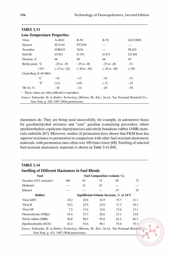
116 Technology of Fluoropolymers, Second Edition
elastomers do. They are being used successfully, for example, in automotive hoses for gasoline/alcohol mixtures and “sour” gasoline (containing peroxides), where epichlorohydrin copolymer depolymerizes and nitrile butadiene rubber (NBR) mate-rials embrittle [67]. Moreover, studies of permeation have shown that FKM hose has superior resistance to permeation in comparison with other fuel-resistant elastomeric materials, with permeation rates often over 100 times lower [68]. Swelling of selected fuel-resistant elastomeric materials is shown in Table 5.14 [69].
Table 5.13low-Temperature PropertiesViton A-401C B-50 B-70 GLT-200S
Dyneon FC2144 FT2350 — —
Tecnoflon FOR532 T636 — PL455
DAI-EL G7451 G-551 G-671 LT-304
Fluorine, % 66 69 66 65
Brittle point, °C –25 to –30 –35 to –40 –35 to –40 –51
(°F)a (–13 to –22) (–30 to –40) (–30 to –40) (–59)
Clash-Berg @ 69 MPaa
°C –16 –13 –19 –31
°F (+2) (+9) (–3) –24
TR 10, °C –18 –14 –20 –30a These values are often difficult to reproduce.
Source: Schroeder, H. in Rubber Technology (Morton, M., Ed.), 3d ed., Van Nostrand Reinhold Co., New York, p. 430, 1987 (With permission).
Table 5.14swelling of Different elastomers in Fuel blends
Fuel Fuel Composition (volume %)
Gasoline (42% aromatic) 100 85 75 85 75
Methanol — 15 25 — —
Ethanol — — — 15 25
Rubber equilibrium volume increase, % at 54°C
Viton AHV 10.2 28.6 34.9 19.7 21.1
Viton B 10.2 22.9 25.6 17.3 18.3
Viton GF 7.5 13.6 14.6 12.6 13.1
Fluorosilicone (FMQ) 16.4 25.3 26.6 23.1 23.0
Nitrile rubber (NBR) 40.8 90.5 95.8 62.4 66.6
Epichlorohydrin (ECO) 42.4 92.6 98.1 75.6 78.5
Source: Schroeder, H. in Rubber Technology (Morton, M., Ed.), 3d ed., Van Nostrand Reinhold Co., New York, p. 431, 1987 (With permission).

Properties, Processing, and Applications of Fluoroelastomers 117
5.1.8.5 Resistance to solvents and Chemicals
As pointed out earlier, fluorocarbon elastomers are highly resistant to hydrocarbons, chlorinated solvents, and mineral acids. Vulcanizates from them swell excessively in ketones and in some esters and ethers. They also are attacked by amines, alkali, and some acids, such as hot anhydrous hydrofluoric acid and chlorosulfonic acid [9]. Generally, stability and solvent resistance increase with increasing fluorine contents, as shown in Table 5.3.
Other than the type of fluorocarbon elastomer used, the main determinant of resistance to acids is the metal oxide used in the compound. Compounds of FKM containing litharge swell markedly less than those containing magnesium oxide or zinc oxide [9]. Compounds based on Kalrez and AFLAS are considerably more resistant to strong alkali and amines than are compounds based on FKM [9].
FKM terpolymers cured with peroxides exhibit exceptional resistance to wet acidic exhaust gases in desulfurization systems in coal-fired plants [63].
5.1.8.6 steam Resistance
Resistance to steam of FKM-based vulcanizates increases with fluorine content. Peroxide cures are superior to diphenol and diamine cures. Compounds based on AFLAS and particularly on Kalrez surpass FKM in this respect [69].
5.1.9 aPPlIcatIons of fkm
Current total worldwide market for fluoroelastomers is estimated at about 21,000 metric tons [5], of which about 60% is automotive, 10% is chemical and petrochemi-cal, 10% is aerospace, and 20% is other markets. Annual growth is estimated at 5% to 8%, mainly for new applications or replacement of parts made previously from inferior elastomers [70]. O-rings and gaskets consume about 30% to 40%, shaft seals and oil seals about 30%, and hoses and profiles 10% to 15% [71–75]. Because of their high price, fluorocarbon elastomers are used in special applications with very high demands on high-temperature resistance and resistance to corrosive chemicals and hot oils. They are most widely used in molded and extruded products, mainly gas-kets used in the aircraft, aerospace, and automotive industries; hoses, membranes, rubber covered rolls, fabrics and in flame resistant coatings on flammable substrates. Because of their dielectric properties, they are used in electrical insulations for low voltages and frequencies when resistance to heat and aggressive chemicals is required. Other applications include food industry, binders for solid rocket fuels, and expanded (foamed) rubber. In the latex form, FKM can be used for coated fabrics and as a binder for fibrous materials. Typical current applications are listed in the following sections.
5.1.9.1 Typical automotive applications
Valve stem and valve seals (Figure 5.4)•Shaft seals•Transmission seals•Engine head gaskets•

118 Technology of Fluoropolymers, Second Edition
Water pump gaskets•Seals for exhaust gas and pollution control equipment•Bellows for turbo-charger lubricating circuits•Fuel-handling systems including diaphragms for fuel pumps (Figure 5.5 •and Figure 5.6), fuel hose or fuel hose liner, inject or nozzle seals, needle valves, filter casing gaskets, fuel shutoff valves, carburetor parts)Speedometer cable seals•
FiGURe 5.4 Valve stem and valve seals. (Courtesy of Daikin)
Fuel pipe withDAI-EL lining
Return pipe
Injector
Fuel pipe withDAI-EL lining
Fuel filter
Inlet pipe
FiGURe 5.5 Fuel pipe with FKM lining. (Courtesy of Daikin.)

Properties, Processing, and Applications of Fluoroelastomers 119
5.1.9.2 Typical aerospace and Military applications
Shaft seals•O-ring seals in jet engines (Figure 5.7)•Hydraulic hose•O-ring seals in fuel, lubricant, and hydraulic systems•Fuel tanks and fuel tank bladders•Manifold gaskets•Lubricating systems•Electrical connectors•
FiGURe 5.6 FKM diaphragms. (Courtesy of Diacom Corporation.)
FiGURe 5.7 O-rings for different applications. (Courtesy of Daikin.)
•• •• •
"',..______ О, - ООО о о

120 Technology of Fluoropolymers, Second Edition
Gaskets for firewalls•Traps for hot engine lubricants•Heat-sealable tubing for wire insulation•Tire valve stem seals•Flares•
5.1.9.3 Chemical and Petrochemical applications
O-rings (Figure 5.7)•Expansion joints•Diaphragms•Blow-out preventers•Valve seats•Gaskets•Hose•Safety clothing and gloves•Stack and duct coatings•Tank linings•Drill bit seals•V-ring packers•
5.1.9.4 other industrial applications
Valve seals•Hose (rubber lined or rubber covered)•Wire and cable covers (in steel mills and nuclear power plants)•Diaphragms (Figure 5.6)•Valve and pump linings•Reed valves•Rubber-covered rolls (100% fluorocarbon elastomer or laminated to •other elastomers)Electrical connectors•Pump lining and seals•Seals in FDA-approved food-handling processes (Figure 5.7)•
5.1.10 aPPlIcatIons of ffkm
Perfluoroelastomers, such as Kalrez, are particularly suited for extreme service con-ditions. They are resistant to more than 1500 chemical substances, including ethers, ketones, esters, aromatic and chlorinated solvents, oxidizers, oils, fuels, acids, and alkali, and are capable of service at temperatures up to 316°C (600°F) [76]. Because of the retention of resilience, low compression set, and good creep resistance, they perform extremely well as static or dynamic seals under conditions where other mate-rials such as metals, FKM, PTFE, and other elastomers fail. Parts from FFKM have very low outgassing characteristics and can be made from formulations that comply with FDA regulations [77]. Primary areas of application of perfluoroelastomers are paint and coating operations, oil and gas recovery, semiconductor manufacture, phar-
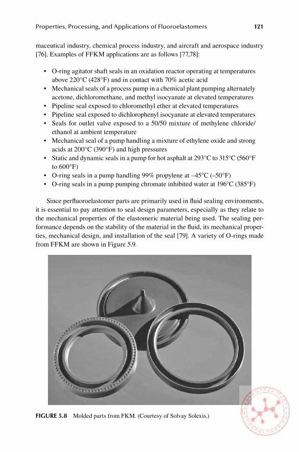
Properties, Processing, and Applications of Fluoroelastomers 121
maceutical industry, chemical process industry, and aircraft and aerospace industry [76]. Examples of FFKM applications are as follows [77,78]:
O-ring agitator shaft seals in an oxidation reactor operating at temperatures •above 220°C (428°F) and in contact with 70% acetic acidMechanical seals of a process pump in a chemical plant pumping alternately •acetone, dichloromethane, and methyl isocyanate at elevated temperaturesPipeline seal exposed to chloromethyl ether at elevated temperatures•Pipeline seal exposed to dichlorophenyl isocyanate at elevated temperatures•Seals for outlet valve exposed to a 50/50 mixture of methylene chloride/•ethanol at ambient temperatureMechanical seal of a pump handling a mixture of ethylene oxide and strong •acids at 200°C (390°F) and high pressuresStatic and dynamic seals in a pump for hot asphalt at 293°C to 315°C (560°F •to 600°F)O-ring seals in a pump handling 99% propylene at –45°C (–50°F)•O-ring seals in a pump pumping chromate inhibited water at 196°C (385°F)•
Since perfluoroelastomer parts are primarily used in fluid sealing environments, it is essential to pay attention to seal design parameters, especially as they relate to the mechanical properties of the elastomeric material being used. The sealing per-formance depends on the stability of the material in the fluid, its mechanical proper-ties, mechanical design, and installation of the seal [79]. A variety of O-rings made from FFKM are shown in Figure 5.9.
FiGURe 5.8 Molded parts from FKM. (Courtesy of Solvay Solexis.)
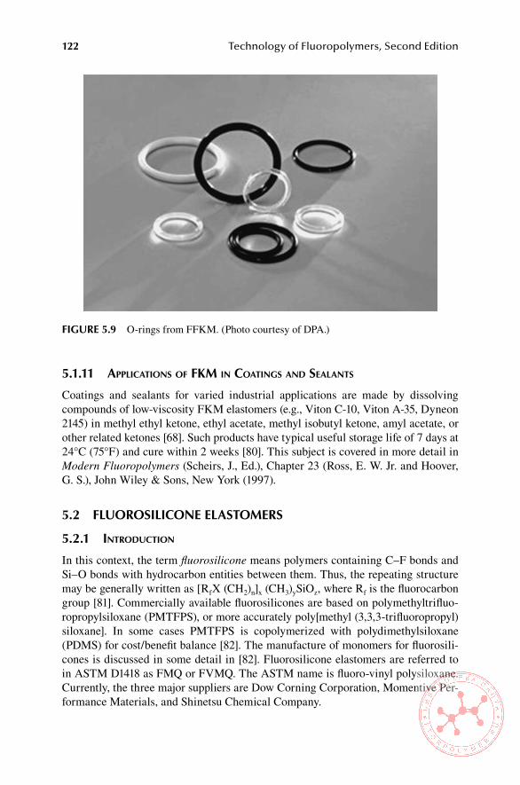
122 Technology of Fluoropolymers, Second Edition
5.1.11 aPPlIcatIons of fkm In coatIngs and sealants
Coatings and sealants for varied industrial applications are made by dissolving compounds of low-viscosity FKM elastomers (e.g., Viton C-10, Viton A-35, Dyneon 2145) in methyl ethyl ketone, ethyl acetate, methyl isobutyl ketone, amyl acetate, or other related ketones [68]. Such products have typical useful storage life of 7 days at 24°C (75°F) and cure within 2 weeks [80]. This subject is covered in more detail in Modern Fluoropolymers (Scheirs, J., Ed.), Chapter 23 (Ross, E. W. Jr. and Hoover, G. S.), John Wiley & Sons, New York (1997).
5.2 FlUoRosiliCone elasToMeRs
5.2.1 IntroductIon
In this context, the term fluorosilicone means polymers containing C–F bonds and Si–O bonds with hydrocarbon entities between them. Thus, the repeating structure may be generally written as [RfX (CH2)n]x (CH3)ySiOz, where Rf is the fluorocarbon group [81]. Commercially available fluorosilicones are based on polymethyltrifluo-ropropylsiloxane (PMTFPS), or more accurately poly[methyl (3,3,3-trifluoropropyl)siloxane]. In some cases PMTFPS is copolymerized with polydimethylsiloxane (PDMS) for cost/benefit balance [82]. The manufacture of monomers for fluorosili-cones is discussed in some detail in [82]. Fluorosilicone elastomers are referred to in ASTM D1418 as FMQ or FVMQ. The ASTM name is fluoro-vinyl polysiloxane. Currently, the three major suppliers are Dow Corning Corporation, Momentive Per-formance Materials, and Shinetsu Chemical Company.
FiGURe 5.9 O-rings from FFKM. (Photo courtesy of DPA.)

Properties, Processing, and Applications of Fluoroelastomers 123
5.2.2 PolymerIzatIon
The most common method of preparation of PMTFPS is through the base-catalyzed ring-opening polymerization of the corresponding cyclic trimer [83,84]. Details are in Chapter 2, Section 2.11.1. A specific cure site for peroxide curing is developed by incorporating 0.2 mol% of methylvinyl siloxane [85]. Typically, fluorosilicone elastomers are copolymers of 90 mol% of trifluoropropylsiloxy and 10 mol% of dimethylsiloxy monomers, but the fluorosilicone content in commercial products ranges from 40 to 90 mol% [85].
Fluorosilicone polymers are optically clear and are available in a broad range of viscosities, from very low viscosity fluids to very high viscosity gums. The physical properties of the raw polymers—such as viscosity; resistance to nonpolar fuels, oils, and solvents; specific gravity; refractive index; lubricity; solubility in polar solvents; the degree of crystallinity; and glass transition temperature (Tg)—depend on the structure, more specifically on the number of trifluoropropyl groups in the molecule. The mechanical properties of the polymer depend on the molecular weight, disper-sity, and mol % of vinyl groups [86]. The presence of fluorine increases the polarity to the level above the standard methylvinyl silicone (MVQ) rubber. Consequently, the fluorosilicone elastomers have a considerably greater resistance to oils and many liquids (with the exception of some ketones and esters) with only slightly impaired resistance low-temperature when compared with MVQ. Still, fluorosilicone elasto-mers have better low-temperature resistance than FKM. Moreover, when compared with FKM they have lower hardness, higher resilience, and a considerably better bonding to other polymers and to metals.
5.2.3 ProcessIng
Fluorosilicones can be compounded by the addition of mineral fillers and pigments. Fillers for such compounds are most commonly silicas (silicon dioxide), because they are compatible with the elastomeric silicon–oxygen backbone and thermally very stable. They range in surface areas from 0.54 to 400 m2/g and average particle size from 100 to 6 nm. Because of these properties, they offer a great deal of flex-ibility in reinforcement. Thus, cured compounds can have Durometer A hardness from 40 to 80. Other fillers commonly used in fluorosilicones are calcium carbonate, titanium dioxide, and zinc oxide.
Mill and mold release is improved by the addition of a small percentage of dime-tylsilicone oils or gums. Processing aids are mostly proprietary. Plasticizers are gen-erally fluorosilicone oils of various viscosities. The lower the molecular weight, the more effective is the plasticizing action. On the other hand, the higher the molecular weight, the lower the volatility. This is critical when the service temperature is very high.
Fluorosilicone compounds can be processed by the same methods used for sili-cone elastomers based on PDMS. They can be milled, calendered, extruded, and molded. A large proportion of fluorosilicone compounds is used in compression molding. Molded parts produced in large series are made by injection molding, and parts with complex shapes are produced by transfer molding. Calendering is used to produce thin sheets and for coating of textiles and other substrates.
124 Technology of Fluoropolymers, Second Edition
Cross-linking of fluorosilicones is done by essentially the same methods as con-ventional silicones. A comprehensive review of this subject is in [87]. Currently, there are three methods of cross-linking used in industrial practice:
Peroxides (free radicals)•Condensation reactions•Hydrosilylation addition•
For peroxide cross-linking, organic peroxides, such as dicumyl, di-t-butyl, and ben-zoyl peroxides, are used in amounts 1 to 3 phr. Typical cure cycles are 5 to 10 min at temperatures 115°C to 170°C (239°F to 338°F), depending on the type of peroxide used. Each peroxide has a specific use. A postcure is recommended to complete the cross-linking reaction and to remove the residues from the decomposition of perox-ide. This improves the long-term heat aging properties [84].
Condensation reactions are used for cross-linking at ambient temperatures. The acetoxy-functional condensation system is widely used in fluorosilicone sealants. The cross-linking occurs after exposure to atmospheric moisture [84]. The limitation of this system is that it is effective for only relatively thin layers. Moreover, it often requires up to 14 days to cure, and the acetic by-product may corrode certain substances.
Thicker sections can be cross-linked by hydrosilylation addition. This is the same chemistry used to produce fluorosilicone monomers with the vinyl functional-ity present on silicon. The catalyst reaction occurs between a vinyl group and sili-cone hydride [88]. The advantage of this system is that it does not produce volatile by-products. On the other hand, the disadvantage is that it is available only as a two-part system [89]. However, one-part, platinum-catalyzed products have been devel-oped [89]. The reaction is very rapid, and at room temperature it is completed in 10 to 30 min. It is accelerated with increasing temperature, and at 150°C (302°F) it is completed within a few seconds. This makes the compounds ideal for fast automated injection molding operations [90]. One-part systems use the chemical complexing of the catalyst, which is activated at elevated temperatures, or its encapsulation into an impermeable shell, which is solid at room temperature and melts at elevated tem-peratures [90].
Fluorosilicone polymers can be cross-linked by ultraviolet radiation or by elec-tron beam, but these methods are not commonly used [91].
5.2.4 ProPertIes
5.2.4.1 Fluid and Chemical Resistance
In general, fluorosilicones exhibit a very good fuel and fluid resistance. The volume swelling in solvents decreases with increasing fluorine content. Cured fluorosilicone elastomers have good resistance to jet fuels, oils, hydrocarbons, and fuels (Table 5.15) [91]. However, higher swelling in ketones and esters are observed [92]. Relatively low swelling is found in alcohol/fuel blends; once the solvents are removed the physical properties return to nearly the original unswollen state [93]. Mechanical properties of PMTFPS elastomers are listed in Table 5.16. A comparison of combined swelling and heat resistance of FMQ with other commercial elastomers is shown in Figure 5.10.
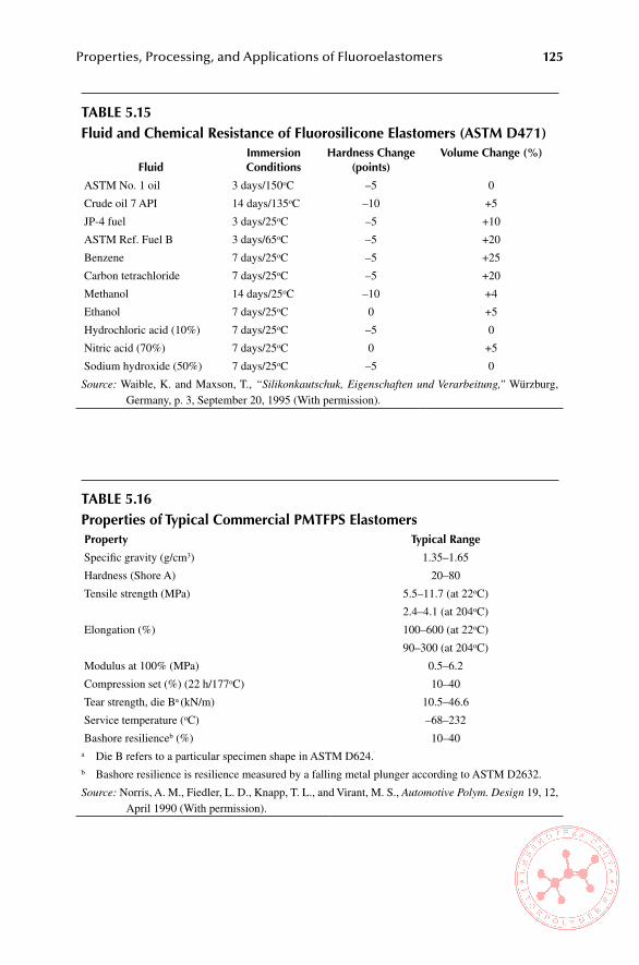
Properties, Processing, and Applications of Fluoroelastomers 125
Table 5.15Fluid and Chemical Resistance of Fluorosilicone elastomers (asTM D471)
Fluidimmersion Conditions
hardness Change (points)
volume Change (%)
ASTM No. 1 oil 3 days/150oC –5 0
Crude oil 7 API 14 days/135oC –10 +5
JP-4 fuel 3 days/25oC –5 +10
ASTM Ref. Fuel B 3 days/65oC –5 +20
Benzene 7 days/25oC –5 +25
Carbon tetrachloride 7 days/25oC –5 +20
Methanol 14 days/25oC –10 +4
Ethanol 7 days/25oC 0 +5
Hydrochloric acid (10%) 7 days/25oC –5 0
Nitric acid (70%) 7 days/25oC 0 +5
Sodium hydroxide (50%) 7 days/25oC –5 0
Source: Waible, K. and Maxson, T., “Silikonkautschuk, Eigenschaften und Verarbeitung,” Würzburg, Germany, p. 3, September 20, 1995 (With permission).
Table 5.16Properties of Typical Commercial PMTFPs elastomers Property Typical Range
Specific gravity (g/cm3) 1.35–1.65
Hardness (Shore A) 20–80
Tensile strength (MPa) 5.5–11.7 (at 22oC)
2.4–4.1 (at 204oC)
Elongation (%) 100–600 (at 22oC)
90–300 (at 204oC)
Modulus at 100% (MPa) 0.5–6.2
Compression set (%) (22 h/177oC) 10–40
Tear strength, die Ba (kN/m) 10.5–46.6
Service temperature (oC) –68–232
Bashore resilienceb (%) 10–40a Die B refers to a particular specimen shape in ASTM D624.b Bashore resilience is resilience measured by a falling metal plunger according to ASTM D2632.
Source: Norris, A. M., Fiedler, L. D., Knapp, T. L., and Virant, M. S., Automotive Polym. Design 19, 12, April 1990 (With permission).
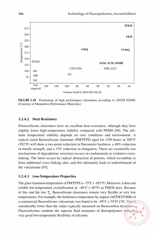
126 Technology of Fluoropolymers, Second Edition
5.2.4.2 heat Resistance
Fluorosilicone elastomers have an excellent heat resistance, although they have slightly lower high-temperature stability compared with PDMS [94]. The ulti-mate temperature stability depends on cure conditions and environment. A typical cured fluorosilicone elastomer (PMTFPS) aged for 1350 hours at 200°C (392°F) will show a two-point reduction in Durometer hardness, a 40% reduction in tensile strength, and a 15% reduction in elongation. There are essentially two mechanisms of degradation: reversion (occurs in confinement) or oxidative cross-linking. The latter occurs by radical abstraction of protons, which recombine to form additional cross-linking sites, and this ultimately leads to embrittlement of the vulcanizate [95].
5.2.4.3 low-Temperature Properties
The glass transition temperature of PMTFPS is –75°C (–103°F). Moreover, it does not exhibit low-temperature crystallization at –40°C (–40°F) as PMDS does. Because of this and the low Tg, fluorosilicone elastomers remain very flexible at very low temperatures. For example, the brittleness temperature by impact (ASTM D746B) of a commercial fluorosilicone vulcanizate was found to be –59°C (–74°F) [74]. This is considerably lower than the values typically measured on fluorocarbon elastomers. Fluorosilicones combine the superior fluid resistance of fluoropolymers with the very good low-temperature flexibility of silicones.
275
250
225
200
175
150
Tem
pera
ture
[°C
]
125
100
70
Notrequired
140
EPDM
IIRCPE/CSM
FVMQ
FKM
FFKM
NBR, ECO
CR
VMQ
AEM, ACM, HNBR
SBRNR
120
Volume Swell in IRM 903 Oil [%]
100 80 60 40 30 20 10
FiGURe 5.10 Positioning of high performance elastomers according to ASTM D2000. (Courtesy of Momentive Performance Materials.)
Properties, Processing, and Applications of Fluoroelastomers 127
5.2.4.4 electrical Properties
Electrical properties—dielectric constant (ε), representing polarization; dissipation factor (tan δ), representing relaxation phenomena; dielectric strength (EB), repre-senting breakdown phenomena; and resistivity (ρv), an inverse of conductivity—are compared with other polymers in Table 5.17 [96]. The low dielectric loss and high electrical resistivity coupled with low water absorption and retention of these prop-erties in harsh environments are major advantages of fluorosilicone elastomers over other polymeric materials [96].
5.2.4.5 surface Properties
Fluorosilicones have low surface energy, in fact lower than polytetrafluoroethylene of polydimethylsiloxane [95]. Values of selected polymers measured at room tem-perature are shown in Table 5.18.
Table 5.17electrical Properties of selected Polymers
Polymer
Dielectric strength
eb (60hz)v/mil
Dielectric Constantε (100 hz)
Dissipation Factor tan δ
Resistivityρv
(ohm.cm)
Low density polyethylene 742 2.2 0.0039 2.5 × 10¹⁵
Natural rubber 665 2.4 0.0024 1.1 × 10¹⁵
PDMS 552 2.9 0.00025 5.3 × 10¹⁴
PMTFPS 350 7.0 0.20 1.0 × 10¹⁴
Viton 351 8.6 0.040 4.1 × 10¹¹
Source: Maxson, M. T., Norris, A. W., and Owen, M. J. in Modern Fluoropolymers (Scheirs, J., Ed.), John Wiley & Sons, Chichester, U.K., p. 366, 1997 (With permission).
Table 5.18surface energy values from selected Polymers
Polymer solid surface energy, σs mJ/m2
PMTFPS 13.6
PDMS 22.8
PTFE 19.1
Note: PMTFPS, polymethyltrifluoropropylsiloxane; PDMS, polydimethyl siloxane; PTFE, polytetrafluoroethylene.
Source: Maxson, M. T., Norris, A. W., and Owen, M. J. in Modern Fluoropolymers (Scheirs, J., Ed.), John Wiley & Sons, Chichester, U.K., p. 364, 1997 (With permission).

128 Technology of Fluoropolymers, Second Edition
5.2.5 aPPlIcatIons
Commercial fluorosilicone elastomer compounds are made from high-molecular-weight PMTFPS (molecular weight is typically 0.8 to 2.0 million) and are cross-linked by organic peroxides. Such compounds contain some reinforcing filler (usually high-surface-area fuming silica), a small amount of low-molecular-weight fluorosilicone diol processing fluid, and a peroxide catalyst [97]. Other additives (e.g., extending fillers, pigments, thermal stability enhancers) are often added to meet final product requirements [98]. Frequently, fluorosilicone elastomers are blended with PDMS silicones either to lower compound cost or to enhance properties of the sili-cone compound. Fluorosilicone elastomers can also be blended with fluoroelasto-mers to improve their low-temperature flexibility. Properties of cured fluorosilicone elastomers depend on the base polymer and compounding ingredients used.
Fluorosilicone elastomers are particularly suited for service where they come in contact with aircraft fuels, lubricants, hydraulic fluids, and solvents. Compared with other fuel-resistant elastomers, fluorosilicones offer the widest hardness range and the widest operating service temperature range of any material [93]. The automo-tive and aerospace industries are the largest users of fluorinated elastomers. Typical automotive applications are fuel injector O-rings, fuel line pulsator seals, and fuel line quick-connect seals; gas cap washers; vapor recovery system seals; electrical connec-tor inserts; exhaust gas recirculating diaphragms; fuel tank access gaskets; and engine cover and oil pan gaskets. In the aerospace industry fluorosilicone O-rings, gaskets, washers, diaphragms, and seals are used in fuel line connections, fuel control devices, electrical connectors, hydraulic line connectors, and fuel system access panels [99].
Medium-molecular-weight PMTFPS with vinyl or hydroxyl end blocks are used for adhesives and sealants. They are cured either at ambient temperature (room temperature vulcanization, or RTV) or at elevated temperature. One-part moisture-activated RTV sealants have been available commercially for many years. Because of their very high resistance to jet engine fuels, excellent flexibility at very low tem-peratures, and high thermal stability, they have been used in both military and civil-ian aerospace applications [100]. Two-part, heat-cured fluorosilicone sealants have been used in military aircraft applications and for sealing automotive fuel systems [101]. A special class of fluorosilicone sealants is channel sealants or groove injec-tion sealants, sticky, puttylike compounds that do not cure. They are used to seal fuel tanks of military aircraft and missiles [97].
Adhesion of fluorosilicone compounds requires surface treatment. For particu-larly difficult surfaces plasma treatment is necessary. However, for most common applications, satisfactory bonding is achieved by using a specialized primer [102].
5.2.6 toxIcIty and safety
Under normal conditions, PMTFPS is relatively inert. Skin tests performed on albino rabbits have shown no dermal irritation or toxicity. In more than 40 years of indus-trial use of fluorosilicone compounds, no problems have been reported with respect to human dermal contact with these materials, uncured or cured [96]. It is prudent to minimize the direct contact with the materials and exposure of personnel to fumes in the workplace. More on this subject is discussed in Chapter 8.

Properties, Processing, and Applications of Fluoroelastomers 129
ReFeRenCes
1. Pierce, O. R., Holbrook, G. W., Johannson, O. K., Saylor, J. C., and Brown, E. D., Ind. Eng. Chem. 52, 783 (1960).
2. Rose, S. H., J. Polym. Sci. B, 6, 873 (1968). 3. Kiker, G. S. and Antkowiak, T. A., Rubber Chem. Technol. 47, 32 (1974). 4. Logothetis, A. L., Prog. Polym. Sci. 14, 251 (1989). 5. World Fluoropolymer Demand by Type and Region, Freedonia Group, Inc., 2007. 6. Banks, R. E., Fluorocarbons and Their Derivatives, Macdonald, London, 17 (1970). 7. Ajroldi, G., Pianca, M., Fumagalli, M., and Moggi, G., Polymer 30, 2180 (1989). 8. Arcella, V. and Ferro, R. in Modern Fluoropolymers (Scheirs, J., Ed.), John Wiley &
Sons, Ltd, Chichester, UK, p. 73 (1997). 9. Schroeder, H. in Rubber Technology (Morton, M., Ed.), 3rd ed., Van Nostrand Reinhold
Co., New York, p. 430 (1987). 10. Scheirs, J. in Modern Fluoropolymers (Scheirs, J., Ed.), John Wiley & Sons, Ltd, Chich-
ester, UK, p. 25 (1997). 11. Scheirs, J. in Modern Fluoropolymers (Scheirs, J., Ed.), John Wiley & Sons, Ltd, Chich-
ester, UK, p. 29 (1997). 12. Scheirs, J. in Modern Fluoropolymers (Scheirs, J., Ed.), John Wiley & Sons, Ltd, Chich-
ester, UK, p. 30 (1997). 13. Scheirs, J. in Modern Fluoropolymers (Scheirs, J., Ed.), John Wiley & Sons, Ltd, Chich-
ester, UK, p. 35 (1997). 14, Novikov, A. S., Galil, F., Slovokhotova, N. A., and Dyumaeva, T. N., Vysokomol. Soed.
4, 423 (1962). 15. Scheirs, J. in Modern Fluoropolymers (Scheirs, J., Ed.), John Wiley & Sons, Ltd, Chich-
ester, UK, p. 52 (1997). 16. Scheirs, J. in Modern Fluoropolymers (Scheirs, J., Ed.), John Wiley & Sons, Ltd, Chich-
ester, UK, p. 53 (1997). 17. Schroeder, H. in Rubber Technology (Morton, M., Ed.), 3rd ed., Van Nostrand Reinhold
Co., New York, p. 413 (1987). 18. Arcella, V., Chiodini, G., Del Fanti, N., and Pianca, M., paper 57 at the 140th ACS Rub-
ber Division Meeting, Detroit, MI (1991). 19. Arcella V. and Ferro R. in Modern Fluoropolymers (Scheirs, J., Ed.), John Wiley &
Sons, Ltd, Chichester, UK, p. 79 (1997). 20. Arcella, V., Geri, S., Tommasi, G., and Dardani, P., Kautsch. Gummi Kunstst. 39, 407
(1986). 21. Arcella, V., Ferro, R., and Albano, M., Kautsch. Gummi Kunstst. 44, 833 (1991). 22. Moore, A.L., Fluoroelastomers Handbook, William Andrew Publishing, Norwich,
NY, 2006, p. 78. 23. Moore, A.L., Fluoroelastomers Handbook, William Andrew Publishing, Norwich,
NY, 2006, p. 79. 24. Arcella V. and Ferro R. in Modern Fluoropolymers (Scheirs, J., Ed.), John Wiley &
Sons, Ltd, Chichester, UK, p. 79 (1997). 25. Arcella V. and Ferro R. in Modern Fluoropolymers (Scheirs, J., Ed.), John Wiley &
Sons, Ltd, Chichester, UK, p. 80 (1997). 26. Brezeale, A.F., U.S. Patent 4,281,092 (July 28, 1981) to E.I. du Pont de Nemours &
Co. 27. Moore, A.L., Fluoroelastomers Handbook, William Andrew Publishing, Norwich,
NY, 2006, p. 93. 28. Lyons, B.J. and Weir, F.E., Radiation Chemistry of Macromolecules (Dole, M., Ed.),
Vol. II, Chapter 14, Academic Press, New York, 1974, p. 294. 29. Vokal, A. et al., Radioisotopy 29 (5-6), p. 426 (1988).

130 Technology of Fluoropolymers, Second Edition
30. McGinnis, V.D. in Encyclopedia of Polymer Science and Engineering, Vol. 4 (Mark, H.F. and Kroschwitz, J.I., Eds.), John Wiley & Sons, New York,, 1986, p. 438.
31. Banik, I. Bhowmick, A.K., Raghavan, S.V., Majali, A.B., and Tikku, V.K., Polymer Degradation and Stability 63(3), p. 413 (1999).
32. Marshall, J.B. in Modern Fluoropolymers (Scheirs, J., Ed.), John Wiley & Sons Ltd., Chichester, UK, 1997 p. 352.
33. Arcella V. and Ferro R. in Modern Fluoropolymers (Scheirs, J., Ed.), John Wiley & Sons, Ltd, Chichester, UK, p. 81 (1997).
34. Hoffmann, W., Rubber Technology Handbook, Carl Hanser Verlag, Munich, 1989, p. 122.
35. Skudelny, D., Kunststoffe/German Plastics 77 (11), 17 (1987). 36. Ferro, R., Giunchi, G., and Lagana, C., Rubber Plastics News, 19 Feb. (1990). 37. Struckmeyer, H., Kautsch. Gummi Kunstst. 43 (9), (1989). 38. Hoffmann, W., Rubber Technology Handbook, Carl Hanser Verlag, Munich, 1989, p.
123. 39. Smith, J. F. and Perkins, G. T., Proc. Inst. Rubb. Conf., Preprint 575 (1959). 40. Moran, A. L. and Pattison, D.B., Rubber World 103, 37 (1971); Schmiegel, W. W., Kau-
tsch. Gummi Kunstst. 31, 137 (1978). 41. Apotheker, D. and Krustic, P.J., U.S. Patent 4,214,060 (1980) to E.I. du Pont de Nem-
ours & Co. 42. Arcella, V. and Ferro, R., in Modern Fluoropolymers (Scheirs, J., Ed.), John Wiley &
Sons, Ltd, Chichester, UK, p. 81 (1997). 43. Schroeder, H. in Rubber Technology (Morton, M., Ed.), 3rd ed., Van Nostrand Reinhold
Co., New York, p. 418 (1987). 44. Schroeder, H. in Rubber Technology (Morton, M., Ed.), 3rd ed., Van Nostrand Reinhold
Co., New York, p. 419 (1987). 45. Stivers, D. A. in The Vanderbilt Rubber Handbook (Winspear, G. G., Ed.), R. T. Van-
derbilt Co., New York, p. 201 (1968). 46. Lynn, M. L. and Worm, A. T. in Encyclopedia of Polymer Science and Technology,
Vol. 7 (Mark, H. F. and Kroschwitz, J. I., Eds.), John Wiley & Sons, New York, p. 265 (1987).
47. Hertz, Jr. D.L. in The Vanderbilt Rubber Handbook 13th edition, R.T Vanderbilt Co., New York, 1990, p. 233.
48. Moore, A.L., Fluoroelastomers Handbook, William Andrew Publishing, Norwich, NY, 2006, p. 104.
49. Moore, A.L., Fluoroelastomers Handbook, William Andrew Publishing, Norwich, NY, 2006, p. 105.
50. Schroeder, H. in Rubber Technology (Morton, M., Ed.), 3rd ed., Van Nostrand Reinhold Co., New York, p. 421 (1987).
51. Moore, A.L., Fluoroelastomers Handbook, William Andrew Publishing, Norwich, NY, 2006, p. 118.
52. Arcella, V. and Ferro, R. in Modern Fluoropolymers (Scheirs, J., Ed.), John Wiley & Sons, Ltd, Chichester, UK, p. 86 (1997).
53. Barwell Preformers, www.barwell.com (2007). 54. Moore, A.L., Fluoroelastomers Handbook, William Andrew Publishing, Norwich,
NY, 2006, p. 110. 55. Molding Solutions, www.molders.com (2007). 56. Rubber Molding, www.hawthornerubber.com (2004). 57. Processing Guide, Viton® Fluoroelastomer Technical Information, Bulletin VTE-
H90171-00-A0703, DuPont Dow Elastomers (2003). 58. Ebnesajjad, S., Fluoroplastics, Vol. 2, Melt Processible Fluoropolymers, Chapter 10,
William Andrew Publishing, Norwich, NY, 2003.

Properties, Processing, and Applications of Fluoroelastomers 131
59. Moore, A.L., Fluoroelastomers Handbook, William Andrew Publishing, Norwich, NY, 2006, p. 119.
60. Arcella, V. and Ferro, R. in Modern Fluoropolymers (Scheirs, J., Ed.), John Wiley & Sons, Ltd, Chichester, UK, p. 87 (1997).
61. Arcella, V. and Ferro, R. in Modern Fluoropolymers (Scheirs, J., Ed.), John Wiley & Sons, Ltd, Chichester, UK, p. 85 (1997).
62. Schroeder, H. in Rubber Technology (Morton, M., Ed.), 3rd ed., Van Nostrand Reinhold Co., New York, p. 423 (1987).
63. Schroeder, H. in Rubber Technology (Morton, M., Ed.), 3rd ed., Van Nostrand Reinhold Co., New York, p. 427 (1987).
64. Schroeder, H. in Rubber Technology (Morton, M., Ed.), 3rd ed., Van Nostrand Reinhold Co., New York, p. 428 (1987).
65. Apotheker, D. et al., Rubber Chem. Technol. 55, 1004 (1982). 66. Geri, S., Lagana, C., and Grossman, R., New Easy Processing Fluoroelastomer, Monte-
dison Paper #30. 67. Nersasian, A., Paper No. 790659 and MacLachlan, J. D., Paper No. 790657, SAE Pas-
senger Car Meeting, Detroit (1979). 68. Schroeder, H. in Rubber Technology (Morton, M., Ed.), 3rd ed., Van Nostrand Reinhold
Co., New York, p. 432 (1987). 69. Schroeder, H. in Rubber Technology (Morton, M., Ed.), 3rd ed., Van Nostrand Reinhold
Co., New York, p. 431 (1987). 70. Arcella, V. and Ferro, R. in Modern Fluoropolymers (Scheirs, J., Ed.), John Wiley &
Sons, Ltd, Chichester, UK, p. 88 (1997). 71. Streit, G., paper presented at the 3rd Brazilian Congress on Rubber Technology, San
Paulo, September (1989). 72. Leblanc, J., Paper 900197, SAE Meeting, February 26–March 2, Detroit, MI (1990). 73. Aloisio, S., Paper 900956, SAE Meeting, February 28–March 2, Detroit, MI (1994). 74. Mastromateo, R., Paper 900195, SAE Meeting, February 26–March 2, Detroit, MI
(1990). 75. Streit, G., Kautsch. Gummi Kunstst. 43 (11), 1990. 76. Prolong the Life of Critical Seals and Rubber Components with KALREZ®, Publica-
tion E86436-01 6/93, DuPont Co., Wilmington, DE. 77. Seal in Savings with KALREZ® Parts, Publication E-78267 3/88, DuPont Co., Wilm-
ington, DE. 78. Kautschuk Technologie (Röthemeyer, F., and Sommer, F., Eds.), Carl Hanser Verlag,
Munich, 2001, Chapter 2.12 (in German). 79. Schnell, R. W., Seal Design Consideration Using KALREZ® Parts, Seal Design Guide,
Publication E-33808-3 7/92, DuPont Polymers, Wilmington, DE. 80. VITON® Technical Bulletin VT-240. C10, E. I. Du Pont de Nemours & Co. 81. Maxson, M. T., Norris, A. W., and Owen, M. J. in Modern Fluoropolymers (Scheirs, J.,
Ed.), John Wiley & Sons, Ltd, Chichester, UK, p. 359 (1997). 82. Maxson, M. T., Norris, A. W., and Owen, M. J. in Modern Fluoropolymers (Scheirs, J.,
Ed.), John Wiley & Sons, Ltd, Chichester, UK, p. 360 (1997). 83. Maxson, M. T., Norris, A. W., and Owen, M. J. in Modern Fluoropolymers (Scheirs, J.,
Ed.), John Wiley & Sons, Ltd, Chichester, UK, p. 361 (1997). 84. Maxson, M. T., Norris, A. W., and Owen, M. J. in Modern Fluoropolymers (Scheirs, J.,
Ed.), John Wiley & Sons, Ltd, Chichester, UK, p. 362 (1997). 85. Hertz, Jr., D. L., in The Vanderbilt Rubber Handbook, 13th ed. (Ohm, R. F., Ed.), R. T.
Vanderbilt Co., New York, p. 239 (1990). 86. Waible, K. and Maxson, T., “Silikonkautschuk, Eigenschaften und Verarbeitung,”
Würzburg, Germany, September 20, 1995, p. 2.
132 Technology of Fluoropolymers, Second Edition
87. Thomas, D. R. in Siloxane Polymers (Clarkson, S. J. and Semlyen, J. A., Eds.), Prentice-Hall, Englewood Cliffs, NJ, 1993, p. 567.
88. Waible, K. and Maxson, T., “Silikonkautschuk, Eigenschaften und Verarbeitung,” Würzburg, Germany, September 20, 1995, p. 4.
89. Maxson, M. T., Norris, A. W., and Owen, M. J. in Modern Fluoropolymers (Scheirs, J., Ed.), John Wiley & Sons, Ltd, Chichester, UK, p. 363 (1997).
90. Waible, K. and Maxson, T., “Silikonkautschuk, Eigenschaften und Verarbeitung,” Würzburg, Germany, September 20, 1995, p. 5.
91. Waible, K. and Maxson, T., “Silikonkautschuk, Eigenschaften und Verarbeitung,” Würzburg, Germany, September 20, 1995, p. 3.
92. Gomez-Anton, M. R., Masegosa, R. M., and Horta, A., Polymer 28, p. 2116 (1987). 93. Norris, A. M., Fiedler, L. D., Knapp, T. L., and Virant, M. S., Automotive Polym. Design
19 (April), p. 12 (1990). 94. Knight, G. J. and Wright, W. W., Br. Polym. J. 21, p. 199 (1989). 95. Maxson, M. T., Norris, A. W., and Owen, M. J. in Modern Fluoropolymers (Scheirs, J.,
Ed.), John Wiley & Sons, Ltd, Chichester, UK, p. 364 (1997). 96. Maxson, M. T., Norris, A. W., and Owen, M. J. in Modern Fluoropolymers (Scheirs, J.,
Ed.), John Wiley & Sons, Ltd, Chichester, UK, p. 366 (1997). 97. Maxson, M. T., Norris, A. W., and Owen, M. J. in Modern Fluoropolymers (Scheirs, J.,
Ed.), John Wiley & Sons, Ltd, Chichester, UK, p. 370 (1997). 98. Maxson, M. T., Gummi Fasern Kunstst. 12, 873 (1995). 99. Maxson, M. T., Norris, A. W., and Owen, M. J. in Modern Fluoropolymers (Scheirs, J.,
Ed.), John Wiley & Sons, Ltd, Chichester, UK, p. 371 (1997). 100. Maxson, M. T., Aerospace Engineering, December, 15 (1990). 101. Maxson, M. T., Norris, A. W., and Owen, M. J. in Modern Fluoropolymers (Scheirs,
J., Ed.), John Wiley & Sons, Ltd, Chichester, UK, p. 369 (1997). 102. Waible, K. and Maxson, T., “Silikonkautschuk, Eigenschaften und Verarbeitung,”
Würzburg, Germany, September 20, 1995, p. 12.

133
6 Technology and Applications of Aqueous Fluoropolymer Systems
6.1 inTRoDUCTion
The majority of fluoropolymers is produced by polymerization in aqueous systems, but in subsequent steps the dispersions obtained in the polymerization process are coagulated into a solid form and converted into powders or pellets. However, some operations, such as impregnation of fabrics or casting of films, can be readily done using aqueous dispersions, suspensions, or latexes. Such systems have advantage over solutions in organic solvents in that they are safer to handle and do not require expensive solvent recovery systems to prevent environmental pollution. Moreover, preparing a solution of a polymer is an additional, often time-consuming operation, requiring specialized equipment and often explosion-proof environment. Finally, most of the perfluoropolymers would not dissolve at all or only in exotic and very expensive solvents, so aqueous systems are the only liquid form in which they are available. The disadvantage of waterborne systems is that they very often dry much slower than the usual solvents (e.g., ketones, esters, chlorinated or fluorinated hydro-carbons) used for some of the fluoropolymers. Furthermore, some additives, such as surfactants, may not be removed completely from the dry film and may have adverse effects on the quality of the final product.
In general, waterborne fluoropolymer systems are handled and processed in a similar fashion as other organic coatings. They can be compounded by addition of fillers, pigments and colorants, resins, and other additives; they can be, for example, viscosified or blended with other waterborne polymeric systems. Because of the nature of the base polymer, they differ in their processing behavior. For example, polytetrafluoroethylene (PTFE) dispersions are very shear sensitive, whereas the others are not. Coating formulations from dispersions of perfluoropolymers are usu-ally very simple, containing only the necessary surfactant. If fillers and pigments are used, the amounts that can be added are limited; otherwise poor-quality films would be obtained. Another aspect to consider is the processing temperature of the polymer; some pigments and colorants cannot tolerate the high processing tempera-tures required for perfluoropolymers. On the other hand, some fluoropolymers can be compounded into highly filled and pigmented coatings and paints.
The following fluoropolymers are commercially available in aqueous systems: PTFE, perfluoroalkoxy (PFA), methylfluoroalkoxy (MFA), fluorinated ethylene pro-pylene (FEP), ethylene tetrafluoroethylene (ETFE), polyvinylidene fluoride (PVDF),

134 Technology of Fluoropolymers, Second Edition
tetrafluoroethylene, hexafluoropropylene, and vinylidene (THV) fluoroplastic, fluo-rocarbon elastomers, fluoroacrylates, and fluorinated polyurethanes.
6.2 PTFe DisPeRsions
Aqueous dispersions of PTFE resin are hydrophobic, negatively charged colloidal systems containing PTFE particles with diameters ranging from 0.05 to 0.5 μm sus-pended in water. Commercial products have a resin content of approximately 60% by weight [1]. Most PTFE dispersions typically contain 6% to 10% of the weight of the resin of nonionic wetting agent and stabilizer (essentially a surfactant). The specific gravity of such dispersion is about 1.50.
PTFE resin dispersions are milky-white liquids, with viscosity of approximately 20 cP and pH about 10. The resin contained therein has the characteristics of fine powders, that is, a high sensitivity to shear.
Upon prolonged standing, the particles, which have specific gravity 2.2 to 2.3 [2], tend to settle with some classification of sizes. During storage, the particles settle gradually to the bottom of the container with gradually increasing clarification of the water phase on the top. Normally, the settled dispersion can be redispersed by gentle agitation completely. Essentially, stabilized dispersions have an indefinite shelf life as long as they are stirred occasionally [3] and kept from freezing.
Unstabilized PTFE dispersions are irreversibly coagulated by acids, electrolytes, and water-miscible solvents, such as alcohol and acetone, and by violent agitation, freezing, and boiling. A small addition of an ionic or nonionic surfactant stabilizes the dispersion so it tolerates some mechanical agitation and addition of water-misci-ble solvents. It also slows sedimentation. The lower limit for an adequate stabiliza-tion is about 1% of the surfactant on the weight of the polymer; however, for most coating and impregnating operations the amount is more like 10% to assure good wetting and penetration. Higher amounts than that may increase the viscosity of the dispersion to an undesirable level. Moreover, for cases where the dried coating is sintered, an increased amount of surfactant (12% or more) increases the amount of time necessary to remove the surfactant in the baking stage of the process (see Section 6.4).
The pH of commercial PTFE dispersions as supplied is usually 10 and tends to drop during storage. Therefore, it is important to check the pH periodically and to maintain it by adding ammonium hydroxide to prevent souring. This is particularly important during warm and humid weather when conditions can promote growth of bacteria. The bacteria feed on the surfactant present in the dispersion, causing a dark brown discoloration and a rancid odor. If souring occurs, the containers must be cleaned out and disinfected with a sodium hypochlorite solution. The ammonium hydroxide used for maintaining pH is usually available as reagent grade of 29%. At this concentration about 5 g/gal of dispersion should be sufficient [4].
The relationship between solids content and gravity is approximately linear and can be expressed by the equation [5]:
V = P(A – B/100 AB) + 1/A, (6.1)

Technology and Applications of Aqueous Fluoropolymer Systems 135
where V is the specific volume of the dispersion, P is the percent by weight of polymer solids, A is the specific gravity of water (0.9985), and B the specific grav-ity of polymer solids (2.25). Examples of specific gravities for different solids are listed in Table 6.1. Determination of specific gravity of a dispersion is by a glass hydrometer.
The viscosity of PTFE dispersions increases proportionally with increasing sol-ids content up to about 30% to 35% solids, and beyond that the increase is much more rapid. Dispersions with surfactants exhibit the same pattern, but the rate of increase is faster and depends on the type and amount of surfactant [5].
6.3 oTheR PeRFlUoRoPolYMeR DisPeRsions
6.3.1 feP dIsPersIons
Commercial aqueous dispersions of FEP are supplied with 54% to 55% by weight of hydrophobic negatively charged particles with the addition of approximately 6% by weight of a mixture of nonionic and anionic surfactants based on polymer content. The particle size range is 0.1 to 0.26 μm. Nominal pH of the dispersion is 9.5, and the viscosity at room temperature is approximately 25 cP (25 mPa.s) [6].
6.3.2 Pfa and mfa dIsPersIons
Commercial aqueous dispersions of PFA contain 50% or more by weight of PFA particles and typically 5% of surfactants on the polymer content [7]. MFA disper-sion, offered by Solvay Solexis, contains 55% by weight of MFA, 4% of nonionic surfactant on the polymer content, and specific gravity 1.41 [8].
6.3.3 dIsPersIons of modIfIed Ptfe
Dispersions of modified PTFE (e.g., Algoflon D3112) are designed for coating processes and are particularly recommended for production of coated fabrics and laminates. Modified PTFE dispersions exhibit good wetting properties, high shear stability, and a good film forming behavior. They are especially suited for topcoat passes to produce final items with improved surface finishing and high gloss.
Table 6.1Correlation between solids Content of PTFe Dispersion and its specific Gravity
solids Content, % specific Gravity amount of solids, g/l
60 1.51 906
50 1.39 695
45 1.34 601
40 1.29 515
35 1.24 436

136 Technology of Fluoropolymers, Second Edition
6.3.4 dIsPersIons of Ptfe mIcroPowders
PTFE micropowders or fluoroadditives (e.g., Zonyl TE-3887, DuPont) are available in aqueous dispersions with 50% to 60% solids. They have very small particle size, typically in the range of 2 to 20 µm, and contain typically 6% of nonionic wet-ting agent and stabilizer. Usual pH of these dispersions is 10. PTFE micropowders are used as additives to paints and coatings, for demolding, and for lubrication (for details see Publication L-13812, 01/07, DuPont).
6.4 PRoCessinG oF PTFe DisPeRsions
The major utility of PTFE dispersions is that they allow processing of PTFE resin, which cannot be processed as ordinary polymeric melt, because of its extraordinarily high melt viscosity, or as solution, because it is insoluble. Thus, PTFE dispersions can be used to coat fabrics and yarns; to impregnate fibers, nonwoven fabrics, and other porous structures; to produce antistick and low-friction coatings on metals and other substrates; and to produce cast films.
Surfactants are an essential ingredient for sufficient wetting of various substrates including sintered PTFE and for the formation of continuous films by uniform spreading on substrates such as metals, glass, ceramics, and polytetrafluoroethyl-ene. Generally, 6% to 10% of nonionic surfactant (e.g., alkylaryl polyether alcohol) based on polymer content is sufficient to impart wetting and film-forming properties. Sometimes a small amount of a fluorosurfactant (typically below 0.1% on the poly-mer content) can be added to increase the efficiency of the nonionic surfactant.
To convert a dispersion into a sintered PTFE film, four distinct steps are required: (1) casting (dipping or flowing out) onto a supporting surface; (2) drying to remove water; (3) baking to remove the surfactant; and (4) sintering to obtain a clear coher-ent film.
For a successful production of a cast film, the dispersion has to wet the support-ing surface and spread uniformly. In drying, the thickness of the deposited layer is very important. If the deposit is too thick, it develops fissures and cracks, referred to as mudcracking. These flaws cannot be eliminated in the sintering step. Thus, for each formulation there is a critical cracking thickness, which represents a limit below which cracking will not occur in a single application. It depends mainly on the particle size range, amount of surfactant used, and solids content. Typical value under optimum conditions is 0.0015 in. [5]. For thicker films multiple coats have to be applied. For a properly formulated dispersion, recoating over an unsintered or sintered coating is not a problem.
6.4.1 ImPregnatIon
Properly compounded PTFE dispersions are suitable for impregnation because of their low viscosity, very small particles, and ability to wet the surfaces. The sur-factant aids the capillary action and wetting interstices in a porous material. After the substrate is dipped and dried, it may or may not be sintered. This depends on the intended application. In fact, the unsintered coating exhibits sufficiently high chemical resistance and antistick property. If required, the coated substrate may be

Technology and Applications of Aqueous Fluoropolymer Systems 137
heated to about 290°C (555°F) for sev-eral minutes to remove the surfactant. Lower temperatures and longer times are used if the substrate cannot tolerate such a high temperature. In some cases, the impregnated material is calendered or compressed in a mold to compact the PTFE resin and to hold it in place.
6.4.2 fabrIc coatIng
6.4.2.1 equipment
The largest proportion of PTFE disper-sions is used for coating glass fabric. Equipment used for that purpose is a vertical coating tower consisting of three heated zones, namely, drying zone, bak-ing zone, and sintering zone (Figure 6.1). There are several systems for heat-ing these zones, and the choice of the heating system depends on the type of product to be made. The most common heating is by circulating hot air heated by gas burners. Air in drying and baking zones can be also heated by circulating hot oil. Infrared heating is another choice, and its use has been growing over the past decade. Each method has its advantages and disadvantages. Gas heating is very effective but requires a relatively long start-up time and is rather inflexible and difficult to control. Hot oil heating is very pre-cise and effective but requires a very long start-up time and represents a very high investment cost and high operation costs. Infrared heating systems are very flexible and relatively inexpensive. They can be switched on and off very quickly, and if they burn out replacement is very simple. Their disadvantage is nonuniform temperature across the width of the web and overall temperature control. In modern production coating towers the heating zones are heated independently.
A typical coating line consists of fabric pay-off, the tower, and a take-up for the coated goods. Some lines also include a festoon (accumulator) to avoid the need for stopping the line if the web is being spliced or if the take-up has to be stopped for roll change or a problem. The take-up may be arranged as a turret for a faster roll change.
A stainless-steel dip tank is on the bottom of the coating tower. Inside the tank is a submerged roll, sometimes called a dip bar, which may be made from stainless steel or PTFE [9]. The roll may be locked or rotated. A rotating bar most frequently has sleeve bearings, which are lubricated by the liquid in the tank. Some designs use multiple rolls (typically three; Figure 6.2); this arrangement reduces differences in pickup between the two sides of the web.
If the process requires wiping of the excess liquid from the web, applicators of different design are used. The most wiping is achieved by sharp knives, the least with
Sinter370°C to 420°C
Bake200°C to 315°C
Dry30°C to 100°C
Applicators
FiGURe 6.1 Schematic of a modern PTFE coating tower. (Reprinted with permission from DuPont Fluoropolymers.)

138 Technology of Fluoropolymers, Second Edition
horizontally opposed, spring-loaded, fixed-gap metering rolls [10]. In actual indus-trial practice the most common wiping devices are round-edged knives, wire-wound rods (Meyer rods) with varied wire diameter, and smooth bars (Figure 6.3).
The larger the wire diameter, the greater thickness of the coating applied. Free dipping (i.e., without wiping) is another possibility. The amount of coating can be also controlled by the amount of solids and by viscosity and to a degree by the web speed.
FiGURe 6.2 Dip tank with three dip bars.
FiGURe 6.3 Detail of coating of glass fabric by PTFE dispersion.

Technology and Applications of Aqueous Fluoropolymer Systems 139
Coating towers can be of straight-up design or can be built in an up-and-down configuration. In the latter design, the drying and baking zones are in the first (“up”) part of the tower, and the sintering zone, including a section for web cooling, is in the “down” part. This design saves space but has the disadvantages that sometimes the baked, unsintered coating is picked up by the rolls on the top of the tower, that the residual surfactant decomposes vigorously at the entry to the sintering zone, and that the products of decomposition condense on the top of the tower, mainly on the rolls. An example of this design is shown in Figure 6.4. Regardless of the design, each tower has an exhaust system on the top for the removal of the volatile decomposition products, which is often coupled with a combustion system to eliminate air pollution. Coating towers are built to process webs up to about 5 m (15 ft) wide, although the majority of them are in the 2 to 3 m (6 to 9 ft) range. A typical production coating tower is shown in Figure 6.5.
The coating speeds depend on the type of fabric and can vary between 0.3 and 14 m/min (1 to 45 ft/min). The speed is also limited by the process; it can be drying, or baking, or sintering. Too high a speed may cause blisters due to insufficient removal of water in the drying zone or insufficient removal of surfactant in the baking zone, which may cause fire in the sintering zone or discoloration of the coating and impaired rewetting of the coating in the subsequent pass. Insufficient sintering (off-white, dull coating) is another possible consequence of too high a coating speed.
1 2
3
45
6
7 8 9 10 8670
270
FiGURe 6.4 Up-and-down design of coating tower. 1, unwinding unit. 2, fabric cleaning unit. 3, tensioning unit. 4, operator platform. 5, dip tank. 6, oven (drying and baking zones). 7, tensioning unit. 8, beta gauge. 9, inspection table, trimming device. 10, wind-up unit. (Cour-tesy Gebrüder Menzel Maschinenfabrik GmbH & Co.)

140 Technology of Fluoropolymers, Second Edition
The temperatures in the individual zones may vary according to the type of fab-ric being coated. However, the goal is to remove water and other volatile components from the coating without boiling and before the web reaches the baking zone and then to remove surfactant in the baking zone. The sintering is almost instantaneous once the temperature is above the crystalline melting point of the PTFE resin. Typi-cal air temperature ranges in the individual zones are as follows:
Drying zone: 80°C to 95°C (176°F to 203°F)Baking zone: 250°C to 315°C (480°F to 600°F)Sintering zone: 360°C to 400°C (680°F to 750°F)
If any of the zones is heated by infrared systems, the surface temperature of the heat-ing elements is set and controlled to attain the required temperature.
6.4.2.2 Formulations
As supplied, PTFE dispersions contain nonionic wetting agent (surfactant), which provides them with good wetting properties and a minimum tendency to foam. Generally, nonionic surfactants are preferred because they are less likely to induce
FiGURe 6.5 Production coating tower in operation.
Technology and Applications of Aqueous Fluoropolymer Systems 141
abnormal viscosities due to thixotropic effects. Other acceptable surfactants are anionic types. Cationic wetting agents are not used because they tend to flocculate the dispersion [4]. The surfactants used in the formulation can be decomposed at the temperatures required for baking, minimizing residual contamination. Other addi-tives, such as mineral fillers or colorants, may be added to achieve desired properties or appearance. Fillers and pigments must be added in the form of a paste, either pur-chased or prepared in house using ball mills or dispersion mills. Often the original PTFE dispersion is diluted by water to attain the required coat thickness.
The viscosity of a dispersion may be increased by adding a water-soluble viscosi-fier. There are several types, for example, hydroxyethyl cellulose (HEC) or acrylic viscosifiers, which are added in the form of an aqueous stock solution. To utilize their viscosifying effects fully, the pH of the formulation must be increased to a certain optimum value, typical for a given viscosifier.
When preparing formulations by blending or adding mineral fillers to PTFE dispersions, only mild agitation must be used. Propeller-type stirrers are best suited for that. High-speed, high-shear mixing is likely to result in coagulation.
6.4.2.3 Coating Process
Glass and aramid fabrics (e.g., Kevlar or Nomex, DuPont) are currently the only fab-rics that can withstand the high temperatures required for sintering of PTFE resin. Thus, they can be coated by it without being degraded greatly in the process. It should be noted that the degradation of these synthetic fabrics is faster than that of glass fabrics. Glass fabrics come with a starch-based treatment (sizing) that is neces-sary in the weaving operation. However, this treatment interferes with the coating and has to be removed by heat cleaning, which means that the fabric is heated to high temperatures to burn off the starch and other organic compounds used in the sizing. This operation is frequently the first pass of the coating process, in which the glass fabric passes through the tower without being coated. In some contemporary designs an infrared heater is placed between the let-off and the dipping tank. This way the treatment is removed in this heater, and the fabric can be coated immedi-ately. This heater also often contains a vacuum cleaner, which removes any loose contaminants from the surface of the fabric.
Depending on the fabric construction and required thickness, the number of passes can be as high as 12 or even more. In some cases undiluted dispersions (with typically 60% solids) are used for at least some of the passes. Each coat must be below the critical cracking thickness to avoid mud cracking. As an alternative, sev-eral unsintered coats are applied, and the coated fabric is then calendered prior to sintering to seal the mud cracks. The calender rolls are heated to temperatures rang-ing from 148°C to 177°C (300°F to 350°F) and operate at a pressure about 1 ton/linear in. to be effective. Wetting agents must be removed completely in the baking zone to prevent the coating from being picked off by the rolls. Calendering is also used to flatten the fabric and to bury filaments, which could be broken during coat-ing [10]. Calenders used for this purpose consist either of one chrome-plated steel roll and a compressed paper backup roll or of two chrome-plated steel rolls. In the former design, only the steel roll can be heated. The result is that there is a difference

142 Technology of Fluoropolymers, Second Edition
in appearance between the two sides of the web, which, depending on the applica-tion, may or may not be a disadvantage. The advantage is that the roll combination exerts a gentler pressure. In the design with two steel rolls, both rolls can be heated, and both sides of the calendered web are smooth. The disadvantage is that the nip may sometimes be too harsh on the glass fibers. However, in general, this design is more effective for the compaction of unsintered PTFE and consequently in sealing the mud cracks.
To obtain PTFE-coated fabrics that can be heat-sealed or laminated at lower temperatures, a thin coat of diluted aqueous dispersions of FEP or PFA is applied on top of the PTFE coating.
6.4.2.4 lamination
PTFE-coated fabrics can be laminated in electrically heated presses at temperatures in the range of 360°C to 400°C (680°C to 750°F) and pressures around 3.4 MPa (500 psi). If the fabric has a coat of FEP or PFA, the lamination temperatures are reduced to be above the melting points of the respective resins. Such fabrics can also be lami-nated on equipment operating continuously. Another lamination process is based on laminating two substrates having an unsintered baked layer of PTFE on the surface. The two adjacent unsintered layers act as a pressure-sensitive adhesive and as result of fibrillation under pressure [11] form a bond sufficiently strong mechanically to survive a free sintering (without pressure). After sintering, the bond will have the heat resistance of PTFE. This process is suitable for the lamination of coated fabrics as well as for lamination of PTFE cast films with PTFE-coated fabrics or a combina-tion of PTFE with other materials in a continuous fashion [11].
6.4.2.5 applications of Coated Fabrics
The largest volume of PTFE-coated fabric is used in construction. The typical appli-cation is as roofing material for large structures, often with minimum support, such as sports buildings (Figure 6.6), shopping malls, airports (Figure 6.7), industrial warehousing, and cooling towers [12,13]. Recently, large tents for huge tent cities in the Middle East were made from PTFE-coated glass fabric. A unique architecture using PTFE-coated glass fabric is shown in Figure 6.8. Other uses are in radomes (Figure 6.9), as belts in ceramic and food industries, as release sheets for laminates of composites, as cooking sheets in fast-food establishments, as release sheets for baked goods, as industrial drying belts, in electrical and electronic industries, and as reinforcement for high-temperature pressure-sensitive tapes. PTFE-coated aramid fabrics laminated to PTFE cast films are used in protective clothing and specialty tents for protection against chemical warfare and as protective clothing in the chemi-cal industry and in firefighting (Figure 6.10).
6.4.3 cast fIlms
6.4.3.1 Cast Film Process
As pointed out earlier, PTFE homopolymer cannot be processed by melt extrusion because of its extremely high melt viscosity. Thus, other methods, such as skiving
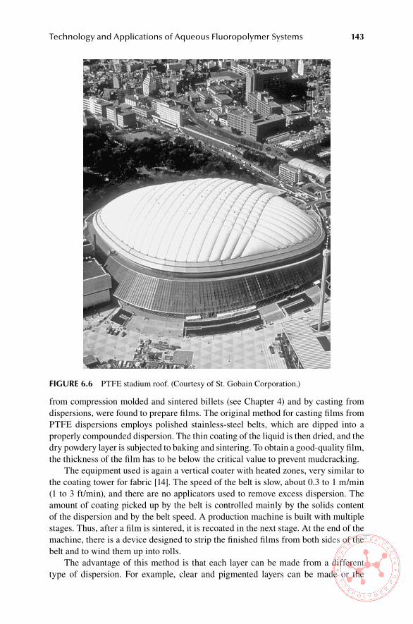
Technology and Applications of Aqueous Fluoropolymer Systems 143
from compression molded and sintered billets (see Chapter 4) and by casting from dispersions, were found to prepare films. The original method for casting films from PTFE dispersions employs polished stainless-steel belts, which are dipped into a properly compounded dispersion. The thin coating of the liquid is then dried, and the dry powdery layer is subjected to baking and sintering. To obtain a good-quality film, the thickness of the film has to be below the critical value to prevent mudcracking.
The equipment used is again a vertical coater with heated zones, very similar to the coating tower for fabric [14]. The speed of the belt is slow, about 0.3 to 1 m/min (1 to 3 ft/min), and there are no applicators used to remove excess dispersion. The amount of coating picked up by the belt is controlled mainly by the solids content of the dispersion and by the belt speed. A production machine is built with multiple stages. Thus, after a film is sintered, it is recoated in the next stage. At the end of the machine, there is a device designed to strip the finished films from both sides of the belt and to wind them up into rolls.
The advantage of this method is that each layer can be made from a different type of dispersion. For example, clear and pigmented layers can be made or the
FiGURe 6.6 PTFE stadium roof. (Courtesy of St. Gobain Corporation.)

144 Technology of Fluoropolymers, Second Edition
FiGURe 6.8 Arabian Tower Hotel in Dubai. (Courtesy of Skyspan Europe GmbH.)
FiGURe 6.7 PTFE roofing elements at the Munich Airport Center. (Courtesy of Skyspan Europe GmbH.)

Technology and Applications of Aqueous Fluoropolymer Systems 145
FiGURe 6.9 Radome from a PTFE coated fabric. (Courtesy of St. Gobain Corporation.)
FiGURe 6.10 Protective clothing from fluoropolymeric laminates. (Courtesy of St. Gobain Corporation.)

146 Technology of Fluoropolymers, Second Edition
top layer can be prepared from an FEP or PFA dispersion to obtain films that can be heat-sealed or laminated. In fact, films with both surfaces heat-sealable can be produced by this method. In such an instance, PFA is applied as the first coat onto the belt and FEP as the last coat, because PFA can be stripped from the steel belt, whereas FEP would adhere to it and be impossible to strip. Another possibility is to make films with an unsintered last coat, which can be used for lamination with substrates coated with unsintered PTFE using the lamination method described in Section 6.4.2.4.
An improved process and equipment for cast PTFE films have been developed that have considerably higher productivity than the method and equipment described in Section 6.4.3.1 [15]. The process essentially uses a vertical coater with multiple stages. The carrier belt has to be made from a material of low thermal mass, which can tolerate repeated exposure to the sintering temperature and has surface proper-ties such that it can be wetted by the dispersion yet the film can be stripped without being stretched. There are several possible belt materials, but Kapton-H (DuPont) was found to be particularly suitable because of its heat resistance, dimensional sta-bility, and surface characteristics [15]. The production speeds used in this process are 3 to 10 m/min (9 to 30 ft/min).
Unlike in the coater with steel belts, in this process equipment applicators such as wire-wound bars are used, which may be designed to rotate to assure a better, more uniform coating. The dip tanks are similar to those used in fabric coating, also using an immersed dip bar. To prevent coating defects due to shear, the dip tanks have double walls and are chilled by circulated chilled water to temperatures below 19°C (66°F), the first-order transition temperature.
The dispersions used in this process are formulated in such a way that they wet the carrier sufficiently and tolerate higher shear at the wire-wound bars due to a rela-tively high coating belt speed. This is accomplished by a combination of nonionic surfactants (e.g., octyl phenoxy polyethoxy ethanol) and fluorosurfactants. This sub-ject is discussed in detail in [15].
6.4.3.2 applications of PTFe Cast Films
Because of the nature of the manufacturing process, there is no melt flow, and conse-quently the cast films do not exhibit anisotropy typical for extruded films. PTFE cast films have higher tensile strength, elongation, and dielectric strength [15]. Another advantage is that they can be produced in layered form from different dispersions (e.g., two colors, with one layer clear, others pigmented, or with one layer having static-dissipative properties, or with one or both layers consisting of melt-processible perfluoropolymers, such as FEP or PFA). If suitable tie-layers are used, it is possible to produce a combination of PTFE film with a bonding layer based on a fluoroelas-tomer or other fluoropolymer, such as lower-melting THV fluoroplastic or PVDF. Films with lower-melting bonding layers can be laminated with substrates that nor-mally would not tolerate the high PTFE sintering temperatures.
Cast PTFE films can be laminated with different substrates, most frequently with PTFE-coated glass and aramid fabrics. They also can be metallized, in particu-lar with aluminum for use in electronics. Other applications include as release films
Technology and Applications of Aqueous Fluoropolymer Systems 147
for the manufacture of composite materials for aerospace vehicles, in electronics and electrical industries, as selective membranes, and in the chemical industry.
6.4.4 other aPPlIcatIons of Ptfe aqueous dIsPersIons
PTFE aqueous dispersions are applied onto metal substrates by spraying, dipping, flow coating, electrodeposition, or coagulation to provide chemical resistance, non-stick, and low-friction surfaces. Nonstick cookware and bakeware are made from dispersion specifically formulated for that purpose with the use of a primer for the metal. In some cases an additional layer (protective layer) between the primer and the top coat is applied. After coating, the parts are dried and sintered. Since PTFE coating tends to be porous, it can be combined with PFA [16]. An example of cook-ware coating is Silverstone, which is a specialty line of highly abrasion resistant nonstick finishes produced by DuPont. Silverstone coatings are three-coat (primer/midcoat/topcoat) systems formulated with PTFE and PFA. Characteristics of Sil-verstone coatings are similar to other PTFE coatings; however, durability is greatly increased because of the proprietory formulation. A ceramic reinforced version with higher scratch and abrasion resistance is also available. Maximum continuous ser-vice temperature of these coatings is 290°C (550°F). An addition of polyphenylene sulfide (PPS) or polyamide imide improves the adhesion of the primer to the metal surface [17]. Besides cookware, PTFE or blends of PTFE and PFA or PTFE and FEP are used to coat, for example, industrial rollers, pipes, storage tanks, pumps, probes, catheters and other medical devices, paper cutters, and drill bits.
PTFE fibers are made by spinning from aqueous dispersions, which are mixed with matrix-forming medium and forced through a spinneret into a coagulating bath. Then the matrix material is removed by heating, and the fibers are sintered and ori-ented (drawn) in the molten state to develop their full strength [18].
Another application of PTFE dispersions is the preparation of a variety of com-positions with other materials, such as mineral fillers, or with other polymers in pow-dered form by coagulation. The dispersion of the other component is blended with the PTFE dispersion, and the blend is then coagulated. The resulting composition can be processed by extrusion with lubricants or by compression molding [19].
6.5 PRoCessinG oF aqUeoUs DisPeRsions oF FeP anD PFa/MFa
6.5.1 ProcessIng
Aqueous dispersions of these two melt-processible perfluoropolymers are processed in a way similar to PTFE dispersion. FEP dispersions can be used for coating fab-rics, metals, and polyimide films. They are very well suited for bonding seals and bearings from PTFE to metallic and nonmetallic components and as nonstick and low-friction coatings for metals [20]. FEP can be fused completely into a continuous film in approximately 1 min at 400°C (752°F) or 40 min at 290°C (554°F) [21]. PFA and MFA dispersions are used to coat various surfaces, including glass fabric, glass, and metals.

148 Technology of Fluoropolymers, Second Edition
6.5.2 aPPlIcatIons
Fabrics coated with FEP and PFA can be laminated and heat-sealed into, for example, protective garments or canopies. FEP-coated polyimide films are used in electronics and as a wire tape. FEP-based anticorrosion coatings are used in the chemical industry and as chemical barriers [21]. A thin coating of FEP or PFA can be used as a hot melt adhesive for a variety of substrates, including PTFE-coated fabrics and laminates.
6.6 PRoCessinG oF aqUeoUs DisPeRsions oF PolYvinYliDene FlUoRiDe
6.6.1 ProcessIng of PVdf dIsPersIons
Commercially available dispersions in latex form (e.g., Kynar Latex 32, Arkema) contain approximately 19% to 20% by weight of homopolymer. They can be pro-cessed as coatings of fabrics or into thin cast films using equipment described in the section on the processing of PTFE dispersions. The fusing temperature for PVDF films is 230°C to 250°C (446°F to 482°F) [22], which is low enough for coating poly-ester fabrics and casting films on carriers that tolerate this temperature.
6.6.2 aPPlIcatIons of PVdf aqueous dIsPersIons
It is possible to cast thin films from PVDF aqueous dispersions. They can be pig-mented and used for decorative surfaces [23]. PVDF aqueous dispersions alone or their blends with acrylic aqueous systems are used for coating fabrics or as decora-tive or protective coatings.
6.7 aqUeoUs DisPeRsions oF Thv FlUoRoPlasTiCs
6.7.1 ProcessIng of thV dIsPersIons
Aqueous dispersions of THV are available with solids content 31% to 34% (THV 220D, THV 340D, THV 510D) and 50% (THV 340C) with the addition of an ionic emulsifier. They can be processed in a similar fashion as dispersions of other melt-processible fluoropolymers, namely, for coating fabrics or casting thin films. Because of their low melting temperatures (140°C to 150°C, or 284°F to 302°F) [24], they can be used to coat polyester fabrics and can be cast on carriers, tolerating the processing temperature (e.g., polyester film). THV aqueous dispersions when properly compounded can be foamed by whipping in a fashion similar to elasto-meric latexes [25].
6.7.2 aPPlIcatIons of thV dIsPersIons
Coated and laminated fabrics (the original application for THV resins) are used in many fabric applications where flexibility, weatherability, or low permeability is required.
Technology and Applications of Aqueous Fluoropolymer Systems 149
Typical applications are protective covers, tarpaulins, awnings, and chemical-protective garments [26]. Thin THV films can be laminated onto temperature- sensitive substrates, such as plasticized polyvinyl chloride (PVC) and polyester [27].
6.8 FlUoRoCaRbon elasToMeRs in laTex FoRM, PRoCessinG anD aPPliCaTions
A certain proportion of fluoroelastomers is used in latex form. The compounding techniques used are similar to those used for standard latexes; i.e., solid ingredients are first dispersed in water with the use of surface active agents and liquid ingredi-ents are prepared as emulsions prior to their addition to the latex. The dispersions of solids are prepared in ball mills or high-speed mills (e.g., Kady Mill).
Fluorocarbon elastomers in the form of highly concentrated latex (typically 70% solids by weight) [28] are used in the coating of fabrics to produce, for example, pro-tective garments and expansion joints. They can be blended with other compatible fluoropolymers and specialty polymers to attain specific properties. Coatings can be cross-linked chemically or by electron beam. Chemically cross-linked coatings can be two- or one-component systems curing at ambient or elevated temperatures. An example of a one-component water-based coating is that developed by Lauren International Co., which uses hydrolyzed and stabilized aminosilanes. Such a system cures to optimum properties in about 1 hour at 100°C (212°F) [29,30]. The con-sumption of fluoroelastomer latexes is growing since they are replacing solutions in volatile organic solvents used in coating applications to comply with lower solvent emission requirement [28].
6.9 healTh anD saFeTY
Aqueous dispersions of fluoropolymers are in general neutral to moderately alkaline, with the exception of certain coatings for metals that are strongly acidic. Some addi-tives in the aqueous phase of the dispersion may irritate eyes or skin. Therefore, it is advisable to use protective garments, goggles, or a facial shield. If the liquid comes in contact with skin, the affected spot must be flushed with water immediately. If the liquid comes in contact with the eyes, they must be flushed immediately and medical help provided as soon as possible.
When aqueous dispersions are processed at elevated temperatures, particularly above the melting point of the dispersed polymer, the same health and safety precau-tions must be taken as when corresponding resins in solid form are processed (see Chapter 10).
ReFeRenCes
1. Teflon® PTFE, Dispersion Properties and Processing Techniques, Bulletin No. X50G, E. I. du Pont de Nemours & Co., Wilmington, DE, Publication E-55541-2, p. 2.
2. Renfrew, M. M. and Lewis, E. E., Ind. Eng. Chem. 38, 870 (1946). 3. Lontz, J. F. and Happoldt, Jr., W. B., Ind. Eng. Chem. 44, 1800 (1952).
150 Technology of Fluoropolymers, Second Edition
4. Teflon® PTFE, Dispersion Properties and Processing Techniques, Bulletin No. X50G, E. I. du Pont de Nemours & Co., Wilmington, DE, Publication E-55541-2, p. 3.
5. Lontz, J. F. and Happoldt Jr., W. B., Ind. Eng. Chem. 44, 1802 (1952). 6. Teflon® FEP 120, Product Information, E. I. du Pont de Nemours & Co., Wilmington,
DE, Publication H-12035-1, p. 1. 7. Gangal, S. V. in Encyclopedia of Polymer Science and Technology, Vol. 16 (Mark, H.
F. and Kroschwitz, J. I., Eds.), John Wiley & Sons, New York, 1989, p. 624 (1989). 8. Hyflon® D 5010X, Technical Information, MFA Dispersion for Impregnation, Solvay
Solexis, 2006. 9. Teflon® PTFE, Dispersion Properties and Processing Techniques, Bulletin No. X50G,
E. I. du Pont de Nemours & Co., Wilmington, DE, Publication E-55541-2, p. 4. 10. Teflon® PTFE, Dispersion Properties and Processing Techniques, Bulletin No. X50G),
E. I. du Pont de Nemours & Co., Wilmington, DE, Publication E-55541-2, p. 6. 11. Effenberger, J. A., Enzien, F. M., Keese, F. M., and Koerber, K. G., U.S. Patent 5,141,800
(August 25, 1992) to Chemical Fabrics Corporation. 12. Forster, B., J. Coated Fabrics 15, July 25 (1985). 13. Fitz, H., Tech. Rdsch. (Bern) 75, No. 51/52, 20th December 10 (1983). 14. Petriello, J. V., U.S. Patent 2,852,811 (September 1958). 15. Effenberger, J. A., Koerber, K. G., Latorra, M. N., and Petriello, J. V., U.S. Patent
5,075,065 (December 24, 1991) to Chemical Fabrics Corporation. 16. Tsai, T.-H., U.S. Patent 5,462,769 (October 31, 1995). 17. Ulrich, H. in Polymer Powder Technology (Narkis, M., and Rosenzweig, N., Eds.),
John Wiley & Sons, Ltd., Chichester, UK, 1995, p.14. 18. Steuber, W., U.S. Patent 3,051,545 (August 28, 1962) to E.I. du Pont de Nemours &
Co. 19. Sperati, C. A. in Handbook of Plastic Materials and Technology (Rubin, I. I., Ed.), John
Wiley & Sons, New York, p. 125 (1990). 20. Gangal, S. V. in Encyclopedia of Polymer Science and Technology, Vol. 16 (Mark, H.
F. and Kroschwitz, J. I., Eds.), John Wiley & Sons, New York, p. 611 (1989). 21. Gangal, S. V. in Encyclopedia of Polymer Science and Technology, Vol. 16 (Mark, H.
F. and Kroschwitz, J. I., Eds.), John Wiley & Sons, New York, p. 624 (1989). 22. Dohany, J. E. and Humphrey, J. S. in Encyclopedia of Polymer Science and Technol-
ogy, Vol. 17 (Mark, H. F. and Kroschwitz, J. I., Eds.), John Wiley & Sons, New York, p. 542 (1989).
23. Dohany, J. E. and Humphrey, J. S. in Encyclopedia of Polymer Science and Technol-ogy, Vol. 17 (Mark, H. F. and Kroschwitz, J. I., Eds.), John Wiley & Sons, New York, p. 543 (1989).
24. 3M THV Fluoroplastics, Technical Information, Publication 98-0211-7012-5, 3M Spe-cialty Fluoropolymers, St. Paul, MN 1998.
25. THV Coating, Publication IPR/8-4-94, American Hoechst Corporation, Leominster, MA.
26. Hull, D. E., Johnson, B. V., Rodricks, I. P., and Staley, J. B. in Modern Fluoropolymers (Scheirs, J., Ed.), John Wiley & Sons, Ltd, Chichester, UK, p. 268 (1997).
27. Hull, D. E., Johnson, B. V., Rodricks, I. P., and Staley, J. B. in Modern Fluoropolymers (Scheirs, J., Ed.), John Wiley & Sons, Ltd, Chichester, UK, p. 269 (1997).
28. Arcella, V. and Ferro, R. in Modern Fluoropolymers (Scheirs, J., Ed.), John Wiley & Sons, Ltd, Chichester, UK, p. 86 (1997).
29. Kirochko, P. and Kreiner, J. G., A New Waterborne Fluoroelastomer Coating, Paper presented at the Conference Fluorine in Coatings III, Grenelefe, Orlando, FL, January 25–27 (1999).
30. Kirochko, P. and Kreiner, J. G., U.S. Patent 5,854,342 (December 29, 1998) to Lauren International Inc.
151
7 Other Fluoropolymers
7.1 aMoRPhoUs FlUoRoPolYMeRs
A family of amorphous fluoropolymers based on copolymers of TFE and perfluro-2,2 dimethyl-1,3 dioxide (PDD) was developed by DuPont under the trade name Teflon AF (amorphous fluoropolymer). They retain the outstanding chemical, thermal, and surface properties associated with perfluorinated polymers and exhibit unique elec-trical, optical, and solubility characteristics at the same time [1]. The structure of Teflon AF is shown in Figure 7.1. PDD is synthesized in four steps from hexafluo-roacetone and ethylene oxide [2]. Hexafluoroacetone condenses with ethylene oxide to form a highly chemically stable dioxolane ring in quantitative yield. Exhaustive chlorination followed by chlorine–fluorine exchange yields 2,2-bistrifluoromethyl-4,5-dichloro-4,5-difluoro-1,3-dioxolane in greater than 90% yield. Dechlorination of this dioxolane with magnesium, zinc, or a mixture of titanium tetrachloride and lithium aluminum hydride gives PDD monomer. PDD is a clear, colorless liquid boil-ing at 33°C (91.4°F). It is highly reactive, and therefore it must be stored with trace amounts of radical inhibitor [2].
PDD readily copolymerizes with tetrafluoroethylene and other monomers con-taining fluorine, such as vinylidene fluoride (VDF), chlorotrifluoroethylene (CTFE), vinyl fluoride (VF), and propylvinyl ether (PVE) via free radical copolymerization, which can be carried out in either aqueous or nonaqueous media. It also forms an amorphous homopolymer with a Tg of 335°C (635°F) [2].
The currently available commercial grades Teflon AF 1600 and Teflon AF 2400 produced by DuPont are copolymers of PDD and tetrafluoroethylene with respective glass transition temperatures of 160°C and 240°C (320°F and 464°F) [2]. They are produced by aqueous copolymerization of PDD and tetrafluoroethylene (TFE) using fluorosurfactant and ammonium persulfate or other metal persulfate initiators [3].
Teflon AF copolymers have a perfluorinated structure as do polytetrafluoroeth-ylene (PTFE), perfluoroalkoxy (PFA), and fluorinated ethylene propylene (FEP), and therefore they exhibit similar high-temperature stability, chemical resistance, low surface energy, and low water absorption. Unlike PTFE, PFA, and FEP, which are semicrystalline, the completely amorphous Teflon AF copolymers differ consider-ably in that they are soluble in several perfluorinated solvents at room temperature and have high optical transmission across a broad wavelength region from ultraviolet (UV) to near infrared [4]. Other differences are lower refractive indexes and dielectric constants and high gas permeability. The refractive index of Teflon copolymers is the lowest known for any solid organic polymer (the respective values for Teflon AF 1600 and AF 2400 are 1.31 and 1.29 at 20°C at the sodium line) and depends on the glass transition temperature of the polymer (Figure 7.2). The presence of the dioxole struc-ture in the chain imparts a higher stiffness and high tensile modulus [4]. Table 7.1

152 Technology of Fluoropolymers, Second Edition
illustrates some of the similarities of Tef-lon AF to commercial perfluoropolymers and some differences between them.
Teflon AF can be processed by a variety of methods. Melt processing includes extrusion, compression, and injection molding. Compression molding is usually done at temperatures 100°C above the glass transition temperatures. Extrusion and injection molding condi-tions depend on the type of part to be produced [5]. Solution-based methods are spin coating and dipping from solu-tions in perfluorocarbon solvents. Spin
coating is used to obtain an ultrathin, uniform-thickness coating on flat surfaces. Nonplanar surfaces can be coated by dipping. Other solution-based methods are spraying with a paint used for more thickly coated layers. Ultrathin layers without the use of solvent are applied by laser ablation [6].
Another perfluoropolymer of this type has been developed by Asahi Glass and is available on the market under the trade name Cytop. This polymer is prepared by cyclopolymerization of perfluorodiene. Its structure is shown in Figure 7.3 [7].
Cytop has physical and chemical properties similar to PTFE and PFA. Its ten-sile strength and yield strength are higher than those of PTFE and PFA. It also has unique optical properties: Its films are transparent in the range from 200 to 700 nm, and its clarity is very high even in the UV region [8]. The properties of CYTOP are shown in Table 7.2 [9]. Cytop is soluble in selected fluorinated solvents. Such solu-tions have a very low surface tension, which allows them to be spread onto porous materials and to cover the entire surface. Films without pinholes and of uniform thickness can be prepared from solutions [8].
(---CF–CF--)x--(--CF2--CF2)y
O O
C
PDD TFECF3 CF3
FiGURe 7.1 Structure of Teflon AF. From Hung, M.-H., Resnick, P. R., Smart, B. E., and Buck, W. H. in Polymer Materials Encyclopedia, Vol. 4 (Salamone, J. C., Ed.), CRC Press, Boca Raton, p. 2467, 1995. With permission.)
1.32
1.31
1.30Refra
ctiv
e Ind
ex
1.29100
(212)Glass Transition Temperature, °C (°F)
150(302)
200(392)
250(482)
300(572)
FiGURe 7.2 Dependence of refractive index of Teflon AF on glass transition temperature. (From http://www2.dupont.com/Teflon_industrial/en_US/), DuPont, 2008. With permission.)
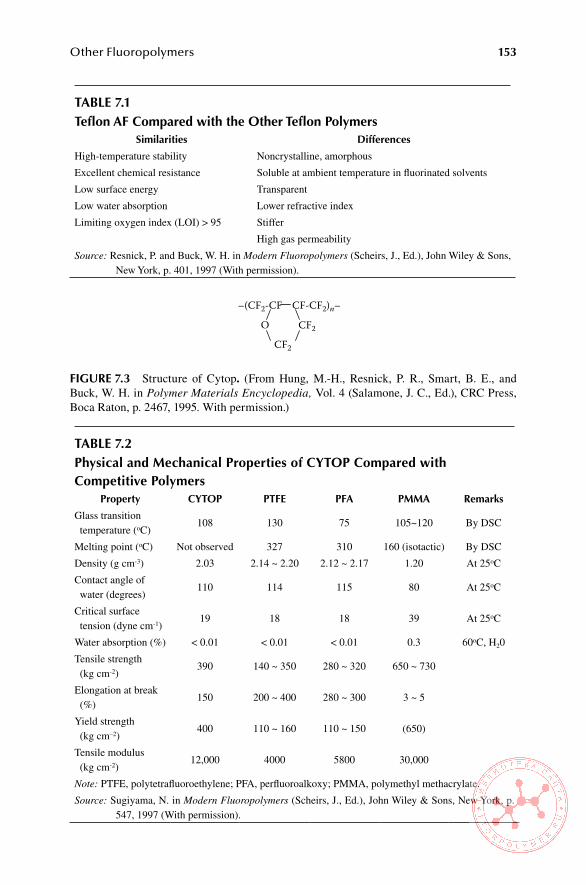
Other Fluoropolymers 153
Table 7.1Teflon aF Compared with the other Teflon Polymers
similarities Differences
High-temperature stability Noncrystalline, amorphous
Excellent chemical resistance Soluble at ambient temperature in fluorinated solvents
Low surface energy Transparent
Low water absorption Lower refractive index
Limiting oxygen index (LOI) > 95 Stiffer
High gas permeability
Source: Resnick, P. and Buck, W. H. in Modern Fluoropolymers (Scheirs, J., Ed.), John Wiley & Sons, New York, p. 401, 1997 (With permission).
Table 7.2Physical and Mechanical Properties of CYToP Compared with Competitive Polymers
Property CYToP PTFe PFa PMMa Remarks
Glass transition temperature (oC)
108 130 75 105~120 By DSC
Melting point (oC) Not observed 327 310 160 (isotactic) By DSC
Density (g cm-3) 2.03 2.14 ~ 2.20 2.12 ~ 2.17 1.20 At 25oC
Contact angle of water (degrees)
110 114 115 80 At 25oC
Critical surface tension (dyne cm-1)
19 18 18 39 At 25oC
Water absorption (%) < 0.01 < 0.01 < 0.01 0.3 60oC, H20
Tensile strength (kg cm-2)
390 140 ~ 350 280 ~ 320 650 ~ 730
Elongation at break (%)
150 200 ~ 400 280 ~ 300 3 ~ 5
Yield strength (kg cm–2)
400 110 ~ 160 110 ~ 150 (650)
Tensile modulus (kg cm-2)
12,000 4000 5800 30,000
Note: PTFE, polytetrafluoroethylene; PFA, perfluoroalkoxy; PMMA, polymethyl methacrylate.
Source: Sugiyama, N. in Modern Fluoropolymers (Scheirs, J., Ed.), John Wiley & Sons, New York, p. 547, 1997 (With permission).
–(CF2-CF CF-CF2)n–
O CF2
CF2
FiGURe 7.3 Structure of Cytop. (From Hung, M.-H., Resnick, P. R., Smart, B. E., and Buck, W. H. in Polymer Materials Encyclopedia, Vol. 4 (Salamone, J. C., Ed.), CRC Press, Boca Raton, p. 2467, 1995. With permission.)

154 Technology of Fluoropolymers, Second Edition
7.1.1 aPPlIcatIons of amorPhous PerfluoroPolymers
The main application of amorphous perfluoropolymers is as cladding of optical fibers, antireflective coatings, and low dielectric coatings, and in the electronic industry (e.g., photoresists) [10–12] and as a low-dielectric-constant insulator for high-performance interconnects [13].
The subject of amorphous perfluoropolymers is covered extensively by P. R. Resnick and W. R. Buck, Chapter 22 (pp. 397–419) and N. Sugiyama in Chapter 28 (pp. 541–555) in Modern Fluoropolymers (Schiers, J., Ed.), John Wiley & Sons, New York (1997) and by M. H. Hung, P. R. Resnick, B. E. Smart, and W. H. Buck, in Polymer Materials Encyclopedia Vol. 4 (Salamone, J. C., Ed.), CRC Press, Boca Raton, FL (1995), pp. 2466–2475.
7.2 FlUoRinaTeD aCRYlaTes
Of a large number of possible fluorinated acrylates, the homopolymers and copo-lymers of fluoroalkyl acrylates and methacrylates are the most suitable for practi-cal applications. They are used in the manufacture of plastic lightguides (optical fibers); resists; water-, oil-, and dirt-repellent coatings; and other advanced applica-tions [14]. Several rather complex methods to prepare the α-fluoroalkyl monomers (e.g., α-phenyl fluoroacrylates, α-(trifluoromethyl) acrylic and its esters, esters of perfluoromethacrylic acid) exist and are discussed in some detail in [14]. Generally, α-fluoroacrylates polymerize more readily than corresponding nonfluorinated acry-lates and methacrylates, mostly by free radical mechanism [15]. Copolymerization of fluoroacrylates has been carried out in bulk, solution, or emulsion initiated with peroxides, azobisisobutyronitrile, or γ-irradiation [16]. Fluoroalkyl methacrylates and acrylates also polymerize by anionic mechanism, but the polymerization rates are considerably slower than those of radical polymerization [17].
The homopolymers of poly(phenyl α-fluoroacrylate) (PPhFA) have a consider-ably higher glass transition temperature than usual acrylates. Its Tg is 180°C (356°F), and it resists to temperatures above 270°C (518°F). Its shortcoming is a rather low resistance to UV radiation. Other polymers, poly(fluoroalkyl methacrylates), exhibit exceptional optical properties. Poly(fluoroalkyl α-fluoroacrylates) (PFAFAs) com-bine that with a greater resistance to elevated temperatures. Homopolymers and copolymers of perfluoroalkyl acrylates and methacrylates exhibit the lowest critical surface tension (γc) of all polymers, including PTFE. Values of γc for these poly-mers, depending mainly on the length, composition, branching, and terminal groups of fluoroalkyl side chains, may be as low as 10.6 dyne/cm as compared with 18.5 to 19 dyne/cm for PTFE [18,19]. Additional, rather comprehensive discussion of fluori-nated acrylic esters is in [20].
7.2.1 aPPlIcatIons of fluorInated acrylates
7.2.1.1 Textile Finishes
The low surface energy of fluoroacrylate polymers makes them suitable for use as water- and oil-repellent coatings for fibers and textiles [21]. At present, the largest
Other Fluoropolymers 155
volume of fluoroacrylates and methacrylates produced in the world is used in this application. A large proportion of these are aqueous dispersions of copolymers of perfluoroalkyl acrylates and perfluoroalkyl methacrylates. These materials success-fully compete with other fluorine-containing compounds for the same application [21]. To achieve the required water- and oil-repellent effect, it is necessary to use copolymers having a perfluoroalkyl pendant group with at least seven atoms. An acrylic polymer with such a structure has an ultimate surface tension value γc = 10.6 dyne/cm, almost half that of PTFE [22,23].
Commercial products, used widely for the treatment of textiles, mainly apparel, soft furnishings, and carpets, are known under the trade names Scotchgard (3M), Teflon (DuPont), Asahigard (Asahi Glass), and Unidyne (Daikin). This subject is reviewed in detail in [24].
7.2.1.2 optical Fibers
At present, fluorinated acrylic ester polymers are commercially used as cladding materials for polymeric optical fibers (POFs), which have cores made of poly(methyl methacrylate), and in some cases for silica optical fibers (polymer-coated fibers, or PCFs). These applications, which are quite sizable, take advantage of the low refractive index that is unique to fluoropolymers [25]. The cladding of POFs is most frequently made from polymethacrylates or poly(2-fluoroacrylates) that have rather short fluoroalkyl side groups, such as CF3CH2–, HCF2CH2–, CF3CF2CH2–, and (CF3)2CH– [26]. In addition, they are often copolymerized with other acrylic ester monomers to adjust the required properties. Although VDF-based resins are also used in claddings, fluorinated acrylic ester polymers exhibit better transparency and lower attenuation loss [27]. PFAFAs exhibit significantly lower refractive indexes and higher thermal stability than similar poly(fluoroalkyl methacrylates) (PFAMAs), but they are considerably higher in cost, which prohibits their wider use [28].
7.2.1.3 other applications
In electronics, fluoroacrylates are used as resists in high-density electronic integrated circuits and as protective coatings in printed circuit boards [29]. They are also often used in xerographic process for negative charge control [30].
In optical applications, in addition to optical fiber claddings, special optical adhe-sives matching refractive indexes of optical glass components based on fluorinated epoxyacrylates and epoxymethacrylates are used [29]. Fluoroalkyl methacrylates are frequently incorporated as comonomers with siloxanyl methacrylates into contact lenses for the improvement of oxygen permeability [31].
Fluorinated acrylic ester polymers are also used as surface modifiers to promote blending instead of coating, imparting functionality of the fluoroalkyl groups to the surfaces of other resins or paints. Since they tend to accumulate on the surface of the substrates facing the air, the surface is easily modified. The modifiers are usually added to paints to enhance leveling or dispersing pigments and sometimes to improve moisture-proof qualities and are blended to resins to give oil and water repellency, or low-friction properties. In addition, they are used as antiblocking agents [32].
156 Technology of Fluoropolymers, Second Edition
7.3 FlUoRinaTeD PolYUReThanes
Introducing fluorine into polyurethane resins results in changes in properties simi-lar to those seen with other polymers. Chemical, thermal, hydrolytic, and oxidative stability is improved. On the other hand, the polymer becomes more permeable to oxygen. Surfaces become more biocompatible, and the capability to bond to other substances in contact with them is diminished [33].
Fluorourethanes are used in products ranging from hard, heat-resistant electri-cal components to biocompatible surgical adhesives. The properties of a specific fluorourethane resin are determined by the raw materials and the manufacturing process used.
Raw materials used for the production of fluorinated polyurethanes are as follows:
Fluorinated alcohols, typically straight-chain alcohols with all but • α and β carbons fluorinated, which are most often usedFluorinated diols•Fluorinated polyols with molecular weights between 500 and 10,000, which •are preferred for most applicationsFluorinated acrylic polyols•Isocyanates and polyisocyanates, mostly nonfluorinated types, which are •used because of their considerably lower cost in comparison with fluori-nated onesMiscellaneous fluorinated precursors, such as amines, anhydrides, oxi-•ranes, alkenes, and carboxylic acids, which are used for special properties
The most frequently used method to prepare fluorourethanes commercially is the well-known addition reaction of polyisocyanates with polyols. Fluorine is most frequently introduced through the polyol component, since fluorinated polyisocya-nates are relatively difficult to obtain and considerably more expensive than the non-fluorinated kind [34]. Examples of fluorinated alcohols for polyurethane resins are listed in Table 7.3 [35].
Another manufacturing method involves irradiation by UV light, in which acrylic-modified polyurethane resins are used. Reactive fluorinated oligomers are reviewed in [36].
Fluorinated polyurethanes may also be prepared by treating the surface of an unfluorinated material with cold plasma of elemental fluorine [37] or carbon tetra-fluoride [38].
7.3.1 aPPlIcatIons of fluorInated Polyurethanes
7.3.1.1 surface Coatings
Because of the low surface energy, resistance to chemicals and corrosive agents, and resistance to weathering, fluorinated polyurethanes are very well suited for protec-tive coatings. They can be deposited in a desired location and thickness with the added advantage of curing mostly at ambient temperatures.
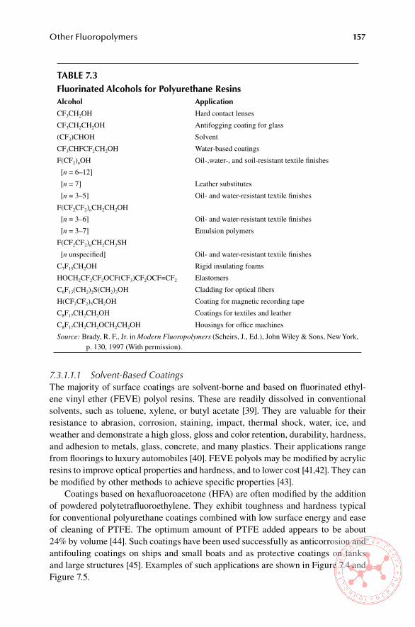
Other Fluoropolymers 157
7.3.1.1.1 Solvent-Based CoatingsThe majority of surface coatings are solvent-borne and based on fluorinated ethyl-ene vinyl ether (FEVE) polyol resins. These are readily dissolved in conventional solvents, such as toluene, xylene, or butyl acetate [39]. They are valuable for their resistance to abrasion, corrosion, staining, impact, thermal shock, water, ice, and weather and demonstrate a high gloss, gloss and color retention, durability, hardness, and adhesion to metals, glass, concrete, and many plastics. Their applications range from floorings to luxury automobiles [40]. FEVE polyols may be modified by acrylic resins to improve optical properties and hardness, and to lower cost [41,42]. They can be modified by other methods to achieve specific properties [43].
Coatings based on hexafluoroacetone (HFA) are often modified by the addition of powdered polytetrafluoroethylene. They exhibit toughness and hardness typical for conventional polyurethane coatings combined with low surface energy and ease of cleaning of PTFE. The optimum amount of PTFE added appears to be about 24% by volume [44]. Such coatings have been used successfully as anticorrosion and antifouling coatings on ships and small boats and as protective coatings on tanks and large structures [45]. Examples of such applications are shown in Figure 7.4 and Figure 7.5.
Table 7.3Fluorinated alcohols for Polyurethane Resinsalcohol application
CF3CH2OH Hard contact lenses
CF3CH2CH2OH Antifogging coating for glass
(CF3)CHOH Solvent
CF3CHFCF2CH2OH Water-based coatings
F(CF2)nOH Oil-,water-, and soil-resistant textile finishes
[n = 6–12]
[n = 7] Leather substitutes
[n = 3–5] Oil- and water-resistant textile finishes
F(CF2CF2)nCH2CH2OH
[n = 3–6] Oil- and water-resistant textile finishes
[n = 3–7] Emulsion polymers
F(CF2CF2)nCH2CH2SH
[n unspecified] Oil- and water-resistant textile finishes
C7F15CH2OH Rigid insulating foams
HOCH2CF2CF2OCF(CF3)CF2OCF=CF2 Elastomers
C6F13(CH2)2S(CH2)3OH Cladding for optical fibers
H(CF2CF2)5CH2OH Coating for magnetic recording tape
C8F17CH2CH2OH Coatings for textiles and leather
C8F17CH2CH2OCH2CH2OH Housings for office machines
Source: Brady, R. F., Jr. in Modern Fluoropolymers (Scheirs, J., Ed.), John Wiley & Sons, New York, p. 130, 1997 (With permission).

158 Technology of Fluoropolymers, Second Edition
FiGURe 7.4 Exterior protective coating on a Coast Guard ship. (Courtesy of 21st Century Coatings, Inc.)
FiGURe 7.5 Protective coating on a bridge. (Courtesy of 21st Century Coatings, Inc.)

Other Fluoropolymers 159
Other coatings prepared from a variety of polyol resins, such as fluorinated acrylic resins, copolymers containing tetrafluoroethylene, vinylidene fluoride, and hexafluoropropylene exhibit generally high gloss, good gloss retention, high resis-tance to weathering, and water repellency [46].
7.3.1.1.2 Water-Based CoatingsThe addition of small amounts of fluorinated polyols to conventional aqueous poly-urethane coatings can improve their water resistance and mechanical properties considerably [47]. FEVE resins can be applied as water-based coatings and cured at 160°C (320°F) for 25 min to produce coatings with high gloss and good water and weather resistance [48]. They may also be cured with water-based hardeners [49].
7.3.1.1.3 Powder CoatingsFluorourethanes can also be applied using powder coating technology. Resins suit-able for this should have Tg values between 35°C and 120°C (95°F and 248°F) to optimize flow out and cure at the annealing temperature. Blocked isocyanates, which form free isocyanates after being heated above certain temperatures, are frequently used [50]. Certain FEVE copolymers with hydroxyl and carboxyl functionalities combined with blocked isophorone diisocyanate are suitable for powder coating technology [51].
7.3.1.2 Treatments of Textile, leather, and other substrates
Surface treatment of textiles, leather, glass, wood, and paper is the second largest appli-cation for fluorinated polyurethanes. The coatings are applied in one-step treatment and impart resistance to soil, water, oil, and stains as well as a smoothness to fabrics and leather that resists removal by many cycles of laundering or dry cleaning [52].
7.3.1.3 Medical and Dental applications
Soft and hard contact lenses with good oxygen permeability, optical clarity, flex-ibility, and biocompatibility; dental composites; denture linings; surgical adhesives; catheters; and hydrophobic microporous membranes are examples of applications of fluorinated polyurethanes in the medical and dental fields [53].
7.3.1.4 Cladding for optical Fibers
Because of their low refractive index (less than 1.43), low permeability of water and weather vapor, very low water absorption, and good adhesion to glass and optical polymers, fluoropolyurethanes are suitable for cladding of optical fibers. A variety of specialty resins are used for this purpose, which are most frequently photocurable.
7.3.1.5 elastomers
Elastomers based on fluorinated polyurethanes exhibit good mechanical properties and resistance to solvents, chemicals, cold, and heat [54]. Formulations for fluo-rourethane elastomers are frequently modified with siloxanes to optimize certain properties [55]. FEVE-based polyols are used to manufacture elastomeric automo-bile bumpers and interior trim components [56].

160 Technology of Fluoropolymers, Second Edition
7.3.1.6 other applications
The versatility of fluorinated polyurethanes is further demonstrated by the follow-ing applications:
Electrical (printed circuit boards, recording media, insulations) [57]•Printing (printing heads, thermal recording media) [58]•Heat exchangers (coatings inside to prevent the formation of deposits) [59]•Binders of explosives [60]•Sealants (used, e.g., for liquid crystal display panels) [61]•Protective coatings for concrete, stone, fibrous materials [62]•Antifogging coatings for mirrors and optical components [63]•
The subject of fluorinated polyurethanes is covered extensively by R. F. Brady, Jr. in Modern Fluoropolymers (Schiers, J., Ed.), John Wiley & Sons, New York, 1997, Chapter 6, pp. 125–163.
7.4 FlUoRinaTeD TheRMoPlasTiC elasToMeRs
Considering the exceptional commercial success of hydrocarbon thermoplastic elas-tomers as a frequent replacement of conventional cross-linked (vulcanized) elasto-mers, it is logical that a similar concept is viable in the field of fluorinated elastomers. This is a particularly attractive concept, considering the rather involved chemistry of cross-linking fluoroelastomers (see Chapter 5). Currently, fluorinated thermoplas-tic elastomers (FTPEs) are produced only in Japan. One is a block-copolymer type, composed of a central soft fluoroelastomer block and multiple fluoroplastic hard seg-ments (ETFE or PVDF, depending on grade; see below). This type has been available commercially since 1982 and is produced by Daikin under the trade name Dai-el thermoplastic [64]. The second type is a graft copolymer type comprising main-chain fluoroelastomers and side-chain fluoroplastics. This type was introduced commer-cially in 1987 by Central Glass Co. under the trade name Cefral Soft [65]. Current estimated combined production of both FTPEs is about 100 tons (data from 1995).
There are essentially two methods used for the production of commercial FTPEs. The first is referred to as iodine transfer polymerization, which is simi-lar to the “living” anionic polymerization used to make block copolymers such as styrene-butadiene-styrene (e.g., Kraton). The difference is that this living polymer-ization is based on a free radical mechanism. The products consist of soft segments based on copolymers of VDF with hexafluoropropylene (HFP) and optionally with TFE and of hard segments that are formed by fluoroplastics such as ETFE or PVDF [66]. The other method is a two-step graft copolymerization using unsaturated per-oxides, such as [CH2=CHCH2OC(O)–O–O–tert-butyl], and the monomers involved are VDF and CTFE. In the second step, postpolymerizations mainly with VDF to form crystalline segments are repeatedly performed while successively raising the reaction temperature [67].
Polyurethane-based FTPEs are produced by reacting fluorinated polyether diols with aromatic diisocyanates. The resulting block copolymers contain fluorinated
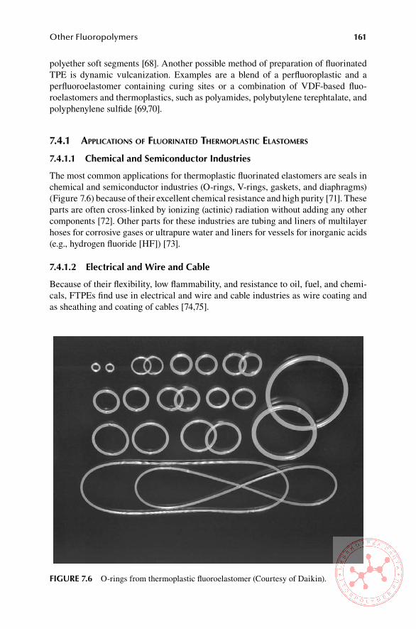
Other Fluoropolymers 161
polyether soft segments [68]. Another possible method of preparation of fluorinated TPE is dynamic vulcanization. Examples are a blend of a perfluoroplastic and a perfluoroelastomer containing curing sites or a combination of VDF-based fluo-roelastomers and thermoplastics, such as polyamides, polybutylene terephtalate, and polyphenylene sulfide [69,70].
7.4.1 aPPlIcatIons of fluorInated thermoPlastIc elastomers
7.4.1.1 Chemical and semiconductor industries
The most common applications for thermoplastic fluorinated elastomers are seals in chemical and semiconductor industries (O-rings, V-rings, gaskets, and diaphragms) (Figure 7.6) because of their excellent chemical resistance and high purity [71]. These parts are often cross-linked by ionizing (actinic) radiation without adding any other components [72]. Other parts for these industries are tubing and liners of multilayer hoses for corrosive gases or ultrapure water and liners for vessels for inorganic acids (e.g., hydrogen fluoride [HF]) [73].
7.4.1.2 electrical and Wire and Cable
Because of their flexibility, low flammability, and resistance to oil, fuel, and chemi-cals, FTPEs find use in electrical and wire and cable industries as wire coating and as sheathing and coating of cables [74,75].
FiGURe 7.6 O-rings from thermoplastic fluoroelastomer (Courtesy of Daikin).
162 Technology of Fluoropolymers, Second Edition
7.4.1.3 other applications
Other applications include tents and greenhouses, as laminates with polyester fiber-reinforced PVC, and as tubing, bottles, and packaging in food processing and in sanitary goods [76].
7.5 CoPolYMeRs oF ChloRoTRiFlUoRoeThYlene anD vinYl eTheR
Fluoropolymers offer several advantages, such as chemical resistance, resistance to UV and weather in general, and excellent dielectric properties. However, because of their poor solubility in solvents and high processing temperatures, their use as pro-tective and dielectric coatings is limited. The method used for some applications and for substrates that can tolerate the high temperature for the film formation is powder coating [77]. PTFE, FEP, PFA, ETFE, and PVDF are applied as antistick and anti-corrosion coatings. PTFE, FEP, PFA, and PCTFE are commonly applied as aque-ous dispersions, and the coating after drying requires high temperatures. From this group, only PVDF is used widely in water dispersion or as a solution in an organic solvent for weather-resistant coatings [78]. Table 7.4 shows some of the conventional fluoropolymers used for coatings.
In an effort to find a fluoropolymer resin suitable for coatings that are soluble in organic solvents and capable of forming a film at ambient temperature, Asahi Glass Co. Ltd. developed copolymers of CTFE and vinyl ether—poly(fluoroethylene vinyl ether) (PFEVE)—and made them available under the trade name LUMIFLON. PFEVE is an amorphous fluoropolymer that is soluble in organic solvents, can form transparent films at ambient temperature, and is compatible with hardeners and pig-ments. All these characteristics make it suitable as a base resin for paints [79]. Com-pared with dispersion paints based on PVDF, PFEVE solvent-based paints have the distinct advantage of forming films at ambient temperature, as mentioned previously. PVDF requires temperatures of 250°C (482°F) or higher to form a continuous film. Moreover, PFEVE can be cured chemically even at room temperature, while PVDF does not contain curable sites. The lower pigment compatibility of PVDF and the higher baking temperature restrict the choice and amount of pigments that can be used [80].
The most recent developments are water-based dispersions of PFEVE [81], some of them cross-linkable with waterborne isocyanates [82]. Another FEVE-based poly-mer, developed and commercialized recently by Asahi Glass Co. Ltd., has the trade name LUMISEAL and is used for high-performance sealants, similar to silicone sealants with the advantage of eliminating the staining problem associated with the latter [83].
7.5.1 aPPlIcatIons of coPolymers of ctfe and VInyl ether
PFEVE-based coatings are used as protective coatings for large architectural struc-tures, such as office buildings and bridges, where on-site coating and curing are required. Other applications are in transportation (automobiles, trains, and ships) and as protective coatings on signs and solar panels [84].
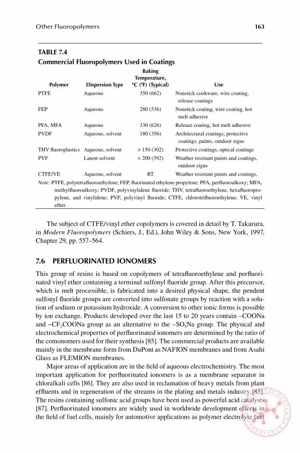
Other Fluoropolymers 163
The subject of CTFE/vinyl ether copolymers is covered in detail by T. Takarura, in Modern Fluoropolymers (Schiers, J., Ed.), John Wiley & Sons, New York, 1997, Chapter 29, pp. 557–564.
7.6 PeRFlUoRinaTeD ionoMeRs
This group of resins is based on copolymers of tetrafluoroethylene and perfluori-nated vinyl ether containing a terminal sulfonyl fluoride group. After this precursor, which is melt processible, is fabricated into a desired physical shape, the pendent sulfonyl fluoride groups are converted into sulfonate groups by reaction with a solu-tion of sodium or potassium hydroxide. A conversion to other ionic forms is possible by ion exchange. Products developed over the last 15 to 20 years contain –COONa and –CF2COONa group as an alternative to the –SO3Na group. The physical and electrochemical properties of perfluorinated ionomers are determined by the ratio of the comonomers used for their synthesis [85]. The commercial products are available mainly in the membrane form from DuPont as NAFION membranes and from Asahi Glass as FLEMION membranes.
Major areas of application are in the field of aqueous electrochemistry. The most important application for perfluorinated ionomers is as a membrane separator in chloralkali cells [86]. They are also used in reclamation of heavy metals from plant effluents and in regeneration of the streams in the plating and metals industry [85]. The resins containing sulfonic acid groups have been used as powerful acid catalysts [87]. Perfluorinated ionomers are widely used in worldwide development efforts in the field of fuel cells, mainly for automotive applications as polymer electrolyte fuel
Table 7.4Commercial Fluoropolymers Used in Coatings
Polymer Dispersion Type
baking Temperature,
ºC (ºF) (Typical) Use
PTFE Aqueous 350 (662) Nonstick cookware, wire coating, release coatings
FEP Aqueous 280 (536) Nonstick coating, wire coating, hot melt adhesive
PFA, MFA Aqueous 330 (626) Release coating, hot melt adhesive
PVDF Aqueous, solvent 180 (356) Architectural coatings, protective coatings, paints, outdoor signs
THV fluoroplastics Aqueous, solvent > 150 (302) Protective coatings, optical coatings
PVF Latent solvent > 200 (392) Weather resistant paints and coatings, outdoor signs
CTFE/VE Aqueous, solvent RT Weather resistant paints and coatings,
Note: PTFE, polytetrafluoroethylene; FEP, fluorinated ethylene propylene; PFA, perfluoroalkoxy; MFA, methylfluoroalkoxy; PVDF, polyvinylidene fluoride; THV, tetrafluoroethylene, hexafluoropro-pylene, and vinylidene; PVF, polyvinyl fluoride; CTFE, chlorotrifluoroethylene; VE, vinyl ether.
164 Technology of Fluoropolymers, Second Edition
cells (PEFCs) [88–93]. The subject of fluorinated ionomers is discussed in much more detail in [85].
7.7 MoDiFieD PolYTeTRaFlUoRoeThYlene
Polytetrafluoroethylene has many remarkable properties (see Chapter 3, Section 3.2.1), but it has several shortcomings that limit its utility as an engineering mate-rial. It exhibits a significant cold flow (low creep resistance), is difficult to weld, and contains a large number of microvoids due to a rather poor coalescence of particles during the sintering process. The weaknesses result from the combination of a high molecular weight (extremely high melt viscosity) and a high degree of crystallinity.
Major research efforts resulted in the development of a modified PTFE, which contains a small amount (0.01 to 0.1 mol%) of a comonomer (see Table 7.5). The most suitable comonomer was found to be perfluoropropylvinyl ether (PPVE) [94]. The comonomer reduces the degree of crystallinity and the size of lamellae [95]. The polymerization process is similar to that for standard PTFE except additives to control the molecular weight are used [96].
The resulting polymer has a melt viscosity lower by an order of magnitude, and because of that the particles coalesce better during sintering. Moreover, it has a mark-edly improved weldability [97]. All important physical properties of commercial modified PTFE are significantly improved without any noticeable reduction of other properties [98,101]. Modified polytetrafluoroethylene is still processed by the same techniques as the standard polymer, and no adjustments to processing techniques are necessary [99]. Because of the lower melt viscosity, modified PTFE performs better in coined molding, blow molding, and thermoforming [100].
Currently, granular molding resins, such as Teflon NXT [70,101], are readily available; however, at least one method of manufacturing a fine powder by aqueous dispersion method is known [102].
Modified PTFE can be used in practically all applications where the conven-tional polymer is used. In addition to that, new applications are possible because of its improved flow and overall performance. In the chemical process industry, it is used for equipment linings, seals, gaskets, and other parts, where its improved resis-tance to creep is an asset. In semiconductor manufacturing, modified PTFE is used in fluid handling components and in wafer processing components. Typical appli-cations in electrical and electronic industries are connectors and capacitor films. Other applications are in unlubricated bearings, laboratory equipment, seal rings for hydraulic systems, and antistick components [103].
7.8 PTFe MiCRoPoWDeRs
PTFE micropowders (also referred to as fluoroadditives) are homopolymers of tet-rafluoroethylene with molecular weight significantly lower than normal PTFE (see Table 7.6). They are prepared mainly by irradiation of PTFE (often of PTFE scrap) by high-energy electron beam [104]. The effect of radiation dose is illustrated by

Other Fluoropolymers 165
Table 7.5Comparison of Modified PTFe and Conventional PTFe
PropertyasTM Test Method Modified PTFe
Conventional PTFe
Tensile strength, MPa D4894 31 34
Elongation at break, % D4894 450 375
Specific gravity D4894 2.17 2.16
Deformation under load at 23°C, % D695
3.4 MPa 0.2 0.7
6.9 MPa 0.4 1.0
13.8 MPa 3.2 8.2
Deformation under load, % D695
6.9 MPa at 25°C 5.3 6.7
3.4 MPa at 100°C 5.4 8.5
1.4 MPa at 200°C 3.6 6.4
Void content of typical parts, % FTIR 0.5 1.5
Dielectric strength, kV/mm (76.2 µm film)
D149 208 140
Weld strength,a % D4894 66-87 Very low
Permeation of perchloroethylene Comparative rates
Vapor 2 5
Liquid 4 13
Permeation of hexane Comparative rates
Vapor 0.2 3.4
Liquid 0 23.4
Note: PTFE, polytetrafluoroethylene.a Specimens welded after sintering
Source: From DuPont Teflon NXT Data Sheets.
Table 7.6Comparison of PTFe Micropowders with standard PTFe Resin
PTFe Grade Molecular Weight Melt viscosity, Pa.s
Micropowders 104–105 10–104
Standard PTFE resin 106–107 10 8–1010
Note: PTFE, polytetrafluoroethylene.

166 Technology of Fluoropolymers, Second Edition
Table 7.7. Another method of producing PTFE micropowders is by controlled polym-erization of TFE to a lower molecular weight [105]. Fluoroadditives are used as addi-tives for plastics, elastomers, coatings, printing inks, paints, lacquers and lubricants, where they provide nonstick and/or sliding properties [106]. Benefits provided by PTFE micropowders are summarized in Table 7.8 [107].
Table 7.7effect of Radiation Dose on Micropowder Particle sizeFeedstock (PTFe) irradiation Dose, kGy Particle size, μm
Unsintered 50 11.1
Unsintered 100 5.3
Unsintered 150 2.5
Unsintered 200 1.5
Sintered scrap 250 0.9
Note: PTFE, polytetrafluoroethylene.
Source: Reference 104
Table 7.8benefits of the Use of PTFe Micropowders in Different applications
application benefit
Coatings of chemical tanks Inert to almost all chemicals and solvents
Engineering polymer parts Reduction of the coefficient of friction
Plastics pulleys and gears Improvement of wear characteristics
Outdoor applications Resistance to UV radiation and weathering
Paints Improvement in nonstick and release properties
Printing inks Increase of rub resistance
Coatings Improvement of corrosion resistance and water repellency
Plastics Improved thermal stability and reduction of coefficient of friction
Wire insulation Improved quality of electrical insulation
Coatings and plastics Reduction or elimination of moisture absorption
Oil and greases Improved lubricity
Mold release agents Improved mold release
Note: PTFE, polytetrafluoroethylene; UV, ultraviolet.
Source: Reference 107
Other Fluoropolymers 167
ReFeRenCes
1. Hung, M.-H., Resnick, P. R., Smart, B. E., and Buck, W. H., in Polymer Materials Ency-clopedia Vol. 4 (Salamone, J. C., Ed.), CRC Press, Boca Raton, p. 2466 (1995).
2. Hung, M.-H., Resnick, P. R., Smart, B. E., and Buck, W. H. in Polymer Materials Ency-clopedia Vol. 4 (Salamone, J. C., Ed.), CRC Press, Boca Raton, p. 2467 (1995).
3. Resnick, P. and Buck, W. H. in Modern Fluoropolymers (Scheirs, J., Ed.), John Wiley & Sons, Ltd, Chichester, UK, p. 399 (1997).
4. Resnick, P. and Buck, W. H. in Modern Fluoropolymers (Scheirs, J., Ed.), John Wiley & Sons, Ltd, Chichester, UK, p. 401 (1997).
5. Resnick, P. and Buck, W. H. in Modern Fluoropolymers (Scheirs, J., Ed.), John Wiley & Sons, Ltd, Chichester, UK, p. 415 (1997).
6. Hung, M.-H., Resnick, P. R., Smart, B. E., and Buck, W. H. in Polymer Materials Ency-clopedia Vol. 4 (Salamone, J. C., Ed.), CRC Press, Boca Raton, p. 2474 (1995).
7. Sugiyama, N. in Modern Fluoropolymers (Scheirs, J., Ed.), John Wiley & Sons, Ltd, Chichester, UK, p. 542 (1997).
8. Resnick, P. and Buck, W. H. in Modern Fluoropolymers (Scheirs, J., Ed.), John Wiley & Sons, Ltd, Chichester, UK, p. 549 (1997).
9. Sugiyama, N. in Modern Fluoropolymers (Scheirs, J., Ed.), John Wiley & Sons, Ltd, Chichester, UK, p. 547 (1997).
10. Resnick, P. and Buck, W. H. in Modern Fluoropolymers (Scheirs, J., Ed.), John Wiley & Sons, Ltd, Chichester, UK, p. 417 (1997).
11. Sugiyama, N. in Modern Fluoropolymers (Scheirs, J., Ed.), John Wiley & Sons, Ltd, Chichester, UK, p. 552 (1997).
12. Sugiyama, N. in Modern Fluoropolymers (Scheirs, J., Ed.), John Wiley & Sons, Ltd, Chichester, UK, p. 553 (1997).
13. Cho, C.-C. Wallace, R. M., and Files-Sesler, L. A., J. Electron. Mater. 23, p. 827 (1994).
14. Chuvatkin, A. A. and Panteleeva, I. Yu. in Modern Fluoropolymers (Scheirs, J., Ed.), John Wiley & Sons, Ltd, Chichester, UK, p. 191 (1997).
15. Chuvatkin, A. A. and Panteleeva, I. Yu. in Modern Fluoropolymers (Scheirs, J., Ed.), John Wiley & Sons, Ltd, Chichester, UK, p. 193 (1997).
16. Chuvatkin, A. A. and Panteleeva, I. Yu. in Modern Fluoropolymers (Scheirs, J., Ed.), John Wiley & Sons, Ltd, Chichester, UK, p. 197 (1997).
17. Narita, T. et al., Macromol. Chem. 187, 731 (1986). 18. Pittman, A. G., in Fluoropolymers (Wall, L. A., Ed.), Wiley-Interscience, p. 446
(1972). 19. Chuvatkin, A. A. and Panteleeva, I. Yu. in Modern Fluoropolymers (Scheirs, J., Ed.),
John Wiley & Sons, Ltd, Chichester, UK, p. 204 (1997). 20. Shimizu, T. in Modern Fluoropolymers (Scheirs, J. Ed.), John Wiley & Sons, Ltd,
Chichester, UK, p. 507 (1997). 21. Ishikawa, N., Fluorine Compounds, Modern Technology and Application, Mir, Mos-
cow (1984), translated from Japanese (edited in Japan 1981). 22. Chuvatkin, A. A. and Panteleeva, I. Yu. in Modern Fluoropolymers (Scheirs, J., Ed.),
John Wiley & Sons, Ltd, Chichester, UK, p. 204 (1997). 23. Pittman, A. G., in Fluoropolymers (Wall, L. A., Ed.), Wiley-Interscience, New York, p.
446 (1972). 24. Kissa, E., Handbook of Fiber Science and Technology, Vol. II, Chemical Processing
of Fibers and Fabrics, Functional Finishes, Part B (Lewin, M. and Sello, S. B., Eds.), Marcel Dekker, New York, Chapters 2 and 3 (1984).
25. Shimizu, T. in Modern Fluoropolymers (Scheirs, J., Ed.), John Wiley & Sons, Ltd, Chichester, UK, p. 517 (1997).

168 Technology of Fluoropolymers, Second Edition
26. Ohomori, A., Tomihashi, N., and Kitahara, T., U.S. Patent 4,729,166 (January 19, 1988) to Daikin Kogyo Co., Ltd.
27. Shimizu, T. in Modern Fluoropolymers (Scheirs, J., Ed.), John Wiley & Sons, Ltd, Chichester, UK, p. 518 (1997).
28. Chuvatkin, A. A. and Panteleeva, I. Yu. in Modern Fluoropolymers (Scheirs, J., Ed.), John Wiley & Sons, Ltd, Chichester, UK, p. 203 (1997).
29. Shimizu, T. in Modern Fluoropolymers (Scheirs, J., Ed.), John Wiley & Sons, Ltd, Chichester, UK, p. 516 (1997).
30. Nomura, Y., Aoki, M., and Nemoto, S., Kokai Tokkyo Koho Japanese Patent 53-97435 (August 25, 1978); Shigeta, K., Takahashi, J., Ohmori, A. et al., Kokai Tokkyo Koho Japanese Patent 61-12069 (June 7, 1986); Yabuuchi, N. and Aoki, T, Kokai Tokkyo Koho Japanese Patent 62-39878 (February 20, 1987).
31. Koßmehl, G., Fluthwedel, A., and Schäfer, H., Makromol. Chem. 193, p. 157 (1992). 32. Shimizu, T. in Modern Fluoropolymers (Scheirs, J. Ed.), John Wiley & Sons, Ltd,
Chichester, UK, p. 521 (1997). 33. Brady, R. F., Jr. in Modern Fluoropolymers (Scheirs, J., Ed.), John Wiley & Sons, Ltd,
Chichester, UK, p. 127 (1997). 34. Brady, R. F., Jr. in Modern Fluoropolymers (Scheirs, J., Ed.), John Wiley & Sons, Ltd,
Chichester, UK, p. 128 (1997). 35. Brady, R. F., Jr. in Modern Fluoropolymers (Scheirs, J., Ed.), John Wiley & Sons, Ltd,
Chichester, UK, p. 130 (1997). 36. Head, R. A, Powell, R. L., and Fitchett, M., Polym. Mater. Sci. Eng. 60, p. 238
(1989). 37. Ozerin, A. N., Rebrov, A. V., Feldman, V. I., Krykin, M. A., Storojuk, A. P., Kotenko,
A. A., and Tul’skii, M. N., React. Funct. Polym. 26, p. 167 (1995). 38. Benoist, P. and Legeay, G., Eur. Polym. J. 30, p. 1283 (1994). 39. Izumi T., Murakami, S., Inagaki, S., and Hirakuri, Y., Japanese Patent 03 281 611
(December 12, 1991). 40. Brady, R. F., Jr. in Modern Fluoropolymers (Scheirs, J., Ed.), John Wiley & Sons, Ltd,
Chichester, UK, p. 144 (1997). 41. Nakao, I., Japanese Patent 06 281 231 (September 6, 1994). 42. Hirashima, Y., Maeda, K., and Tutsumi, K., Japanese Patent 07 76 667 (March 20,
1995). 43. Brady, R. F., Jr. in Modern Fluoropolymers (Scheirs, J., Ed.), John Wiley & Sons, Ltd,
Chichester, UK, p. 145 (1997). 44. Brady, R. F., Jr., Griffith, J. R., Love, K. S., and Field, D. E., J. Coatings Technol. 59
(77), p. 113 (1987). 45. Brady, R. F., Jr. in Polymers in a Marine Environment (Goring, D., Ed.), The Institute
of Marine Engineers, London, 191 (1989). 46. Brady, R. F., Jr. in Modern Fluoropolymers (Scheirs, J., Ed.), John Wiley & Sons, Ltd,
Chichester, UK, p. 147 (1997). 47. Yang, S., Xiao, H. X., Chen, W. P., Kresta, J., Frisch, K. C., and Higley, D. P., Progr.
Rubber Plast. Technol. 7, 163 (1991). 48. Okazaki, H., Fujii, S., and Tonomura, S., Japanese Patent 04 131 165 (May 1, 1992). 49. Kodama, S., Yamauchi, M., Hirino, T., and Kitahata, H., Japanese Patent 07 179 809
(July 18, 1995). 50. Sugimoto, K. and Saka, J., Japanese Patent 05 186 565 (July 27, 1993). 51. Yasumura, T., Kobayashi, S., and Komoriya, H., European Patent Application EP 556
729 (August 25, 1993). 52. Brady, R. F., Jr. in Modern Fluoropolymers (Scheirs, J., Ed.), John Wiley & Sons, Ltd,
Chichester, UK, p. 148 (1997).
Other Fluoropolymers 169
53. Brady, R. F., Jr. in Modern Fluoropolymers (Scheirs, J., Ed.), John Wiley & Sons, Ltd, Chichester, UK, p. 150 (1997).
54. Menough, J., Rubber World, p. 9 (January 1989). 55. Koike, N. and Sato, S., Japanese Patent 06 234 923 (August, 23, 1994). 56. Maruyama, T. and Nakamoto, M., Japanese Patent 03 167 276 (July 19, 1991). 57. Brady, R. F., Jr. in Modern Fluoropolymers (Scheirs, J., Ed.), John Wiley & Sons, Ltd,
Chichester, UK, p. 153 (1997). 58. Brady, R. F., Jr. in Modern Fluoropolymers (Scheirs, J., Ed.), John Wiley & Sons, Ltd,
Chichester, UK, p. 152 (1997). 59. Brady, R. F., Jr. in Modern Fluoropolymers (Scheirs, J., Ed.), John Wiley & Sons, Ltd,
Chichester, UK, p. 154 (1997). 60. Hoeller, R. and Rudolf, K., European Patent Application EP 316 891 (May 24, 1992). 61. Brady, R. F., Jr. in Modern Fluoropolymers (Scheirs, J., Ed.), John Wiley & Sons, Ltd,
Chichester, UK, p. 155 (1997). 62. Brady, R. F., Jr. in Modern Fluoropolymers (Scheirs, J., Ed.), John Wiley & Sons, Ltd,
Chichester, UK, p. 152 (1997). 63. Honda, T. and Kaetsu, I., Japanese Patent 06 172 675 (June 21, 1994). 64. Tatemoto, M., Int. Polym. Sci. Technol. 12, 4 (1985). 65. Kawashima, C., in Fusso Jushi Handbook (Satokawa, T., Ed.), Nikkan Kogyu Shinbun-
sya, Tokyo, pp. 671–686 (1984). 66. Tatemoto, M. and Shimizu, T. in Modern Fluoropolymers (Scheirs, J., Ed.), John Wiley
& Sons, Ltd, Chichester, UK, p. 566 (1997). 67. Tatemoto, M. and Shimizu, T. in Modern Fluoropolymers (Scheirs, J., Ed.), John Wiley
& Sons, Ltd, Chichester, UK, p. 567 (1997). 68. Tonelli, C., Trombetta, T., Scicchitano, M., Simeone, G., and Ajroldi, G., J. Appl.
Polym. Sci. 59, p. 311 (1996). 69. Logothetis, A. L. and Stewart, C. W., U.S. Patent 4,713,418 (December 15, 1987) to E.
I. Du Pont de Nemours & Co. 70. Goebel, K. D. and Nam, S., Proc. 3rd Int. Conf. Thermopl. Elastomer, Mark. Prod. p.
55 (1966). 71. Tatemoto, M. and Shimidzu, T. in Modern Fluoropolymers (Scheirs, J., Ed.), John
Wiley & Sons, Ltd, Chichester, UK, p. 563 (1997). 72. Tatemoto, M., Tomoda, M., Kawachi, M. et al., Kokai Tokkyo Koho Japanese Patent
62635 (April 10, 1984). 73. Kawashima, C. and Koga, S., Jpn. Plast. 39, p. 98 (1988). 74. Cheng, T. C., Kaduk, B. A., Mehan, A. K., Taft, D.D., Weber, C.J., Zingheim, S.C., U.S.
Patent 4,935,467 (June 19, 1988 to Raychem Corp.. 75. Katsuragawa, S., Kawashima, C., and Masaki, T., U.S. Patent 4,749,610 (June 7, 1988)
to Central Glass Co. Ltd. 76. Tatemoto, M. and Shimizu, T., in Modern Fluoropolymers (Scheirs, J., Ed.), John Wiley
& Sons, Ltd, Chichester, UK, p. 575 (1997). 77. Khaladkar, P. R., Mat. Performance (MP) 33, p. 35 (1994). 78. Takakura, T. in Modern Fluoropolymers (Scheirs, J., Ed.), John Wiley & Sons, Ltd,
Chichester, UK, p. 559 (1997). 79 Munekata, S., Progr. Org. Coatings 16, p. 113 (1988). 80. Takakura, T. in Modern Fluoropolymers (Scheirs, J., Ed.), John Wiley & Sons, Ltd,
Chichester, UK, p. 561 (1997). 81. Yamauchi, M. et al., Europ. Coatings J., p. 124 (1996). 82. Takakura, T. in Modern Fluoropolymers (Scheirs, J., Ed.), John Wiley & Sons, Ltd,
Chichester, UK, p. 563 (1997). 83. Takakura, T. in Modern Fluoropolymers (Scheirs, J., Ed.), John Wiley & Sons, Ltd,
Chichester, UK, p. 564 (1997).
170 Technology of Fluoropolymers, Second Edition
84. Takakura, T. in Modern Fluoropolymers (Scheirs, J., Ed.), John Wiley & Sons, Ltd, Chichester, UK, p. 562 (1997).
85. Grootaert, W. M., in Encyclopedia of Polymer Science and Engineering, Vol. 16 (Mark, H. F. and Kroschwitz, J. I., Eds.), John Wiley & Sons, New York, p. 641 (1989).
86. Dotson, R. L. and Woodard, K. E., in Perfluorinated Ionomer Membranes, ACS Sym-posium Series 180 (Eisenberg, A. and Yeager, H. L., Eds.) (1982).
87. Olah, G. A., Synthesis, July, p. 513 (1986). 88. Ralph, T. R., Hards, G. A., Flint, S. D., and Gascoyne, J. M., in 1998 Fuel Cell Sem-
inar, Palm Springs Convention Center, Palm Springs, CA, Nov. 16–19, p. 536 (1998). 89. Sugawara, Y., Uchida, M., Ohara, H., Fukuoka, Y., Eda, N., and Ohta, A., in 1998 Fuel
Cell Seminar, Palm Springs Convention Center, Palm Springs, CA, Nov. 16–19, p. 613 (1998).
90. Lee, E. H., Oh, T. Y., and Baek, K. K., in 1998 Fuel Cell Seminar, Palm Springs Con-vention Center, Palm Springs, CA, Nov. 16–19, p. 620 (1998).
91. Passalacqua, E., Lufrano, F., Squadrito, G., Patti, A., and Giorgi, L. in 1998 Fuel Cell Seminar, Palm Springs Convention Center, Palm Springs, CA, Nov. 16–19, p. 636 (1998).
92. Jung, D. H., Lee, C. H., Chun, Y. G., Peck, D. H., Kim, C. S., and Shin, D. R. in 1998 Fuel Cell Seminar, Palm Springs Convention Center, Palm Springs, CA, Nov. 16–19, p. 695 (1998).
93. Wakizoe, M., Murata, H., and Takei, H. in 1998 Fuel Cell Seminar, Palm Springs Con-vention Center, Palm Springs, CA, Nov. 16–19, p. 487 (1998).
94. Doughty, T. R., Jr. and Sperati, C. A., U.S. Patent 3,855,191 (December 17, 1974) to E. I. Du Pont de Nemours & Co.
95. Hintzer, K. and Löhr, G. in Modern Fluoropolymers (Scheirs, J., Ed.), John Wiley & Sons, Ltd, Chichester, UK, p. 240 (1997).
96. Hintzer, K. and Löhr, G. in Modern Fluoropolymers (Scheirs, J., Ed.), John Wiley & Sons, Ltd, Chichester, UK, p. 243 (1997).
97. Hintzer, K. and Löhr, G. in Modern Fluoropolymers (Scheirs, J., Ed.), John Wiley & Sons, Ltd, Chichester, UK, p. 251 (1997).
98. Sulzbach, R. and Tschacher, M., Angew. Makromol. Chem. 109/110, 113 (1982). 99. Hintzer, K. and Löhr, G. in Modern Fluoropolymers (Scheirs, J., Ed.), John Wiley &
Sons, Ltd, Chichester, UK, p. 2254 (1997). 100. Michel, W., Kunststoffe/German Plastics 79, No. 10, 984 (1989). 101. TEFLON® NXT 70 Fluoropolymer Resin, Modified PTFE Granular Molding Resin,
Publication 2474696 C (4/98), DuPont Fluoroproducts, Wilmington, DE (1998). 102. Treat, T. A. and Malhotra, S. C., U.S. Patent 5,731,394 (March 24, 1998) to E.I. du Pont
de Nemours & Co. 103. TEFLON® NXT Benefits, www.teflon.com/nxt DuPont Fluoroproducts, Wilmington,
DE (2008). 104. Dillon, J.A., U.S. Patent 3,766,031 to Garlock Inc. (October 16, 1973). 105. Mayer, L., Tonnes, K.- U., and Bladel, H., U.S. Patent 5,641,571 to Hoechst A.G.
(1995). 106. Daikin Polyflon™ TFF Low Polymer, Daikin Industries Ltd., Osaka (1992) 107. Ebnesajjad, S., Fluoroplastics, Volume 1, William Andrew Publishing, Norwich, NY,
p. 199 (2000).

171
8 Effects of Heat, Radiation, and Environment on Fluoropolymers
8.1 eFFeCTs oF heaT
Generally, fluoropolymers are among the organic materials with the highest resis-tance to thermal degradation; however, there are significant differences between them. Relative thermal stability of selected fluoropolymers was studied by ther-mogravimetry [1]. The findings indicated that ethylene tetrafluoroethylene (ETFE) has the lowest thermal stability, which can be explained by the presence of ethylene linkages in its molecule. Fluorinated ethylene propylene (FEP) is next, and in spite of being fully fluorinated its lower-than-expected thermal stability is very likely due to a high degree of –CF3 branching. Perfluoroalkoxy (PFA) is more stable than FEP because of the presence of a stable, highly shielded ether group in its struc-ture [2]. Polytetrafluoroethylene (PTFE) is the most stable of this group since its hydrocarbon backbone is protected by the large fluorine atoms attached by a very strong bond. There are two competing thermal degradation mechanisms, namely, unzipping (depolymerization) to form monomer and chain transfer reactions. The high-energy, very strong C–F bond makes depolymerization the dominant mecha-nism, whereas weaker C–H and C–Cl bonds promote thermal degradation by chain transfer reaction [2].
8.1.1 thermal degradatIon of PerfluoroPlastIcs
PTFE is extremely inert and stable up to temperatures of 250°C (482°F). When heated above that temperature, it begins to decompose very slowly, giving rise to small quantities of gaseous products. For example, the initial rate of weight loss for granular PTFE has been reported as 0.0001%/h at 260°C (500°F) and 0.004%/h at 371°C (700°F) [3]. Thermal degradation of PTFE at different temperatures is illus-trated in Table 8.1.
Vacuum thermal degradation of PTFE results in monomer formation, and stud-ies established it to be a first-order reaction [4]. Mass spectroscopic analysis of PTFE indicates that degradation starts at about 440°C (824°F), peaks at 540°C (1004°F), and continues until 590°C (1094°F) [5]. Because of that, processing PTFE at tempera-tures above 400°C (752°F) is not recommended. Inhalation of the fumes evolved dur-ing processing causes an influenza-like syndrome described as polymer fume fever (PFF) [6], which is further worsened by smoking tobacco. The signs and symptoms, following a latent interval of a few hours, usually subside after 24 to 48 h without aftereffects.

172 Technology of Fluoropolymers, Second Edition
Thermal degradation of PTFE is one of the methods to produce PTFE micro-powders (for details, see Chapter 7)
FEP has a considerably lower thermal stability than PTFE and starts to degrade at temperatures above 200°C (392°F). There are essentially two stages in the deg-radation of FEP. The first involves preferential elimination of hexafluoropropylene (HFP) from the backbone; in the second the remaining backbone undergoes decom-position at the same rate as that of PTFE [7].
PFA is more stable thermally than FEP because of the presence of stable ether groups in the side chain (see above); however, it can degrade during processing or use at high temperatures due to the presence of reactive end groups (e.g., –COF or –CH2OH). The result is cross-linking reactions and an increase in the molecular weight when the end groups decompose to form radicals, which then undergo radi-cal recombination reactions [8]. PFA resins can be processed at temperatures up to 445°C (883°F). Aging below but near the temperature of 285°C (545°F) increases the strength of PFA [9].
8.1.2 thermal degradatIon of other fluoroPlastIcs
Polyvinylidene fluoride (PVDF) is considerably less thermally stable than PTFE but much more stable than polyvinyl fluoride (PVF) or polychlorotrifluoroethylene (PCTFE). Certain inorganic compounds (silica, titanium dioxide, and antimony oxide) can catalyze its decomposition at temperatures above 375°C (707°F) [10].
ETFE degradation is autocatalytic and similar to that of PVDF and is accompa-nied by the evolution of hydrogen fluoride (HF). Iron and transition metal salts can accelerate the degradation of ETFE by dehydrofluorination and oligomer formation [10]. Copper salts have been found to stabilize the polymer [11]. ETFE decomposes rapidly at temperatures above 380°C (716°F) [11].
PVF decomposes in air at temperatures above 350°C (682°F) by dehydrofluori-nation. At approximately 450°C (842°F), backbone cleavage occurs [9]. PVF films discolor at high temperatures but retain considerable strength after heat-aging at 217°C (423°F) [12].
Table 8.1Thermal Degradation of Polytetrafluoroethylene
Temperature, oC
Rate of Decomposition, %/h
Fine Powder
Granular
initial steady state
232 0.0001–0.0002 0.00001–0.00005 1 × 10-11
260 0.0006 0.0001–0.0002 100 × 10-11
316 0.005 0.0005 0.000002
371 0.03 0.004 0.0009
Source: Gangal, S. V., in Kirk-Othmer Encyclopedia of Chemical Technology, Vol. 11, 3d ed., John Wiley & Sons, New York, p. 11, 1980 (With permission).

Effects of Heat, Radiation, and Environment on Fluoropolymers 173
Ethylene chlorotrifluoroethylene (ECTFE) has a thermal stability comparable to ETFE [13] and can be stabilized by the addition of an ionomer, which considerably reduces dehydrofluorination and dehydrochlorination reactions and suppresses the discoloration of the polymer [14].
PCTFE can start to degrade at temperatures as low as 250°C (452°F). The mech-anism of thermal degradation of PCTFE is a chain scission and leads to terminal unsaturation [14]. Since the processing temperature range from 230°C to 290°C (446°F to 554°F) approaches the decomposition temperature of the polymer, it is important to maintain tight temperature control during the processing of PCTFE. During thermal degradation, the polymer also tends to become brittle as a result of increasing crystallinity. The tendency to embrittle during high-temperature use can be offset by copolymerizing PCTFE with a small amount of vinylidene fluoride (VDF) (usually less than 5%) [13].
8.1.3 thermal degradatIon of fluorocarbon elastomers
8.1.3.1 Degradation of Perfluoroelastomers
Perfluoroelastomers (ASTM designation FFKM) such as copolymers of tetrafluoro-ethylene (TFE) and perfluoromethylvinyl ether (PMVE) can maintain their thermal stability to temperatures as high as 300°C (572°F) or even higher, with a maximum continuous service temperature of 315°C (599°F). Moreover, instead of hardening, the elastomer becomes more elastic with aging [13].
8.1.3.2 Degradation of other Fluorocarbon elastomers
Fluoroelastomers (ASTM designation FKM) such as copolymers of VDF and HFP typically have a maximum continuous service temperature of 215°C (419°F). Some metal oxides may cause dehydrofluorination at a temperature of 150°C (302°F) or even lower [16]. Copolymers of VDF and CTFE (e.g., Kel-F) have a maximum long-term service temperature of 200°C (392°F). Fluorocarbon elastomers based on copo-lymers of VDF/HPFP (hydropentafluoropropylene) and on terpolymers of VDF/HPFP/TFE have lower thermal stability than copolymers of VDF/HFP because they have a lower fluorine content than the latter [17]. A detailed study of thermal stability of fluoroelastomers was performed by Cox, Wright, and Wright [18].
8.1.4 thermal degradatIon of fluorosIlIcones
Thermal degradation of fluorosilicones can occur by a reversion mechanism and is accelerated by the presence of basic compounds. The maximum long-term service of fluorosilicone elastomers depends on cure conditions and environment and is typi-cally 200°C (392°F) [19].
8.2 eFFeCTs oF ionizinG RaDiaTion
As in the case of many other polymeric materials, ionizing radiation electron beam, or EB, and gamma radiation has a variety of effects on fluoropolymers. It may
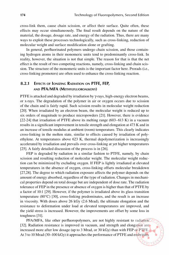
174 Technology of Fluoropolymers, Second Edition
cross-link them, cause chain scission, or affect their surface. Quite often, these effects may occur simultaneously. The final result depends on the nature of the material, the dosage, dosage rate, and energy of the radiation. Thus, there are many ways to exploit these processes technologically, such as cross-linking, reduction of molecular weight and surface modification alone or grafting.
In general, perfluorinated polymers undergo chain scission, and those contain-ing hydrogen atoms in their monomeric units tend to predominantly cross-link. In reality, however, the situation is not that simple. The reason for that is that the net effect is the result of two competing reactions, namely, cross-linking and chain scis-sion. The structure of the monomeric units is the important factor here. Prorads (i.e., cross-linking promoters) are often used to enhance the cross-linking reaction.
8.2.1 effects of IonIzIng radIatIon on Ptfe, feP, and Pfa/mfa (methylfluoroalkoxy)
PTFE is attacked and degraded by irradiation by γ-rays, high-energy electron beams, or x-rays. The degradation of the polymer in air or oxygen occurs due to scission of the chain and is fairly rapid. Such scission results in molecular weight reduction [20]. When irradiated by an electron beam, the molecular weight is reduced up to six orders of magnitude to produce micropowders [21]. However, there is evidence [22-24] that irradiation of PTFE above its melting range (603–613 K) in a vacuum results in a significant improvement in tensile strength and elongation at 473 K and in an increase of tensile modulus at ambient (room) temperature. This clearly indicates cross-linking in the molten state, similar to effects caused by irradiation of poly-ethylene. At temperatures above 623 K, thermal depolymerization is increasingly accelerated by irradiation and prevails over cross-linking at yet higher temperatures [25]. A fairly detailed discussion of the process is in [26].
FEP is degraded by radiation in a similar fashion to PTFE, namely, by chain scission and resulting reduction of molecular weight. The molecular weight reduc-tion can be minimized by excluding oxygen. If FEP is lightly irradiated at elevated temperatures in the absence of oxygen, cross-linking offsets molecular breakdown [27,28]. The degree to which radiation exposure affects the polymer depends on the amount of energy absorbed, regardless of the type of radiation. Changes in mechani-cal properties depend on total dosage but are independent of dose rate. The radiation tolerance of FEP in the presence or absence of oxygen is higher than that of PTFE by a factor of 10:1 [29]. However, if the polymer is irradiated above its glass transition temperature (80°C) [30], cross-linking predominates, and the result is an increase in viscosity. With doses above 26 kGy (2.6 Mrad), the ultimate elongation and the resistance to deformation under load at elevated temperatures are improved, and the yield stress is increased. However, the improvements are offset by some loss in toughness [31].
PFA/MFA, like other perfluoropolymers, are not highly resistant to radiation [32]. Radiation resistance is improved in vacuum, and strength and elongation are increased more after low dosage (up to 3 Mrad, or 30 kGy) than with FEP or PTFE. At 3 to 10 Mrad (30–100 kGy) it approaches the performance of PTFE and embrittles
Effects of Heat, Radiation, and Environment on Fluoropolymers 175
above 10 Mrad (100 kGy). After the exposure to the dosage of 50 Mrad (500 kGy), PTFE, FEP, and PFA are all degraded [33].
8.2.2 effects of IonIzIng radIatIon on other fluoroPlastIcs
ETFE retains its tensile properties when exposed to low-level ionizing radiation, because the two competing processes, namely, chain scission and cross-linking, are occurring at an approximately equal rate so the net change in molecular weight is quite small. At higher levels of radiation, the tensile elongation of ETFE is severely affected and drops sharply when irradiated [34]. The change in mechanical proper-ties is much pronounced in the presence of air [35]. The radiation resistance of ETFE is superior to both PTFE and FEP.
Cross-linking of ETFE improves its high-temperature properties, such as cut-through by a hot soldering iron, and increases the continuous service temperature from 150°C (302°F) to 200°C (392°F) [36]. Further improvement is achieved by the use of prorads (radiation promoters) such as triallyl cyanurate (TAC) or triallyl iso-cyanurate (TAIC) in amounts up to 10% by weight [25].
PVDF and its copolymers undergo cross-linking when exposed to low-level radiation (up to 20 Mrad, or 200 kGy) as indicated by the increased gel fraction with increased dose [37,38]. Cross-linking in PVDF usually results in an increase in tensile strength of the polymer and in a reduction of both the degree of crystal-linity and melting point. The overall radiation resistance to nuclear radiation is very good. Its tensile strength is virtually unaffected after 1000 Mrad (10,000 kGy) of γ radiation in vacuum, and its impact strength and elongation are slightly reduced as a result of cross-linking. The only adverse effect observed on PVDF after radia-tion is discoloration, which has already occurred at relatively low doses [39]. It is attributed to the formation of double bonds due to dehydrofluorination [40]. PVDF and its copolymers are significantly thermally destabilized by radiation doses above 100 kGy; therefore, for a sufficiently efficient cross-linking, polyunsaturated mono-mers such as TAC, TAIC, bis(maleimido-methyl) ether, and ethylene bis-maleimide should be used [41].
PVF becomes cross-linked as PVDF and forms a gel fraction when exposed to ionizing radiation. Irradiated PVF exhibits higher tensile strength, and resistance to etching increases with increasing dose; however, as in PVDF, the degree of crys-tallinity and melting point decrease [36]. As PVDF, it is significantly destabilized by radiation doses above 100 kGy, also requiring prorads for a sufficient degree of cross-linking [41].
ECTFE behaves upon irradiation like ETFE, including improvement of cross-linking efficiency with the addition of prorads. Irradiation at room temperature fol-lowed by heat treatment at and above 435 K in nitrogen for 20 min is reported to be most effective [25].
Very little work has been reported on the effects of irradiation of PCTFE. One source claims that the resistance of PCTFE to ionizing radiation is superior to that of other fluoropolymers [42]. Another work reports that poly(chlorotrifluoroethylene) degrades when exposed to ionizing radiation in a similar fashion as PTFE at ambient

176 Technology of Fluoropolymers, Second Edition
and elevated temperatures. Unlike PTFE, when irradiated above its crystalline melt-ing point, it still exhibits chain scission [31].
Amorphous perfluoroplastics developed by DuPont (Teflon AF) and Asahi Glass (Cytop) contain bulky structures that are responsible for the absence of crystallinity. When Teflon AF was irradiated by low-energy x-rays, it was found that the inclusion of the dioxole monomer not only improves the optical properties but also increases the radiation tolerance of the homopolymer [43].
8.2.3 effects of IonIzIng radIatIon on fluorocarbon elastomers
8.2.3.1 effects on FKM Type of Fluorocarbon elastomers
FKM type of fluoroelastomers, particularly copolymers of HFP and VDF, are cross-linked by low-level γ radiation (up to 20 Mrad or 200 kGy) in the same fashion as PVDF. Radiation degradation of a VDF-HFP copolymer was studied by Zhong and Sun [44]. Their finding was that there is a linear relationship between the dose and the weight loss of the polymer. Fluorocarbon elastomers based on copolymers of TFE and propylene were found to be more resistant to γ radiation than Viton elastomers [45]. Cross-linking of VDF-HFP, VDF-TFE, and tetrafluoroethylene-pro-pylene (TFE/P) copolymers as well as of terpolymers VDF-HFP-TFE by ionizing radiation (gamma or electron beam) can be enhanced by prorads, such as TAIC and trimethylolpropane trimethacrylate (TMPTM) [46]. It appears that each fluorocar-bon elastomer has the best cross-link yield with a specific prorad. In general, opti-mized compounds from fluorocarbon elastomers irradiated at optimum conditions attain considerably better thermal stability and mechanical properties than chemical curing systems [47–49]. Typical radiation dose for a sufficient cross-linking of most fluorocarbon elastomers is on the range of 10 to 100 kGy.
8.2.3.2 effects on Perfluoroelastomers
Perfluoroelastomers (ASTM designation FFKM) are essentially copolymers of two perfluorinated monomers, TFE and PMVE, with a cure site monomer (CSM), which is essential for cross-linking. Depending on the nature of the CSM and on the cur-ing conditions, they are capable of service temperatures up to 300°C. Perfluoroelas-tomers can be cured by ionizing radiation (EB and γ-rays) without any additives. The advantage of radiation cured FFKM is the absence of any additives, so that the product is very pure. The disadvantage is the relatively low upper use temperature of the cured material, typically 150°C, which limits the material to special sealing applications only [50].
8.3 eFFeCTs oF Uv RaDiaTion
Fluoropolymers as a group have intrinsically high resistance to degradation by UV radiation. The strength of the fluorine–carbon bond makes them resistant to pure photolysis. Moreover, they do not contain any light-absorbing chromophores either in their structure or as impurities. For example, no physical or chemical changes have been observed during 30 years of continuous exposure of PTFE in Florida [38].
Effects of Heat, Radiation, and Environment on Fluoropolymers 177
The outdoor durability of a fluorinated coating is directly related to its fluorine con-tent and is assessed by gloss retention [51].
The degradation of some fluoropolymers outdoors occurs very slowly and can be detected only by very sensitive analytical methods, such as x-ray photoelectron spectroscopy (XPS) [52] or electron spin resonance (ESR) spectroscopy [53].
To assess the propensity of a polymer to UV degradation accurately, it is impor-tant to pay attention to the wavelength of the UV light employed. For example, FEP polymers absorb UV radiation only at wavelengths below 180 nm, which makes them susceptible to degradation only in the space [54]. Unlike FEP and other perfluoropo-lymers, degradation of PCTFE is greatly accelerated by UV light [55]. Copolymers of TFE and HFP have been reported to undergo scission and cross-linking when exposed to UV radiation [56].
ReFeRenCes
1. Baker, B. B. and Kasporzak, D. J., J. Polym. Degrad. Stab., 42, 181 (1993). 2. Scheirs, J., in Modern Fluoropolymers (Scheirs, J., Ed.), John Wiley & Sons, Ltd,
Chichester, UK, p. 49 (1997). 3. Gangal, S. V., in Kirk-Othmer Encyclopedia of Chemical Technology, Vol. 11, 3rd ed.,
John Wiley & Sons, New York, p. 11 (1980). 4. Siegle, J. C.., Muus, L.T., in T.-P., and Larsen, A.H., J. Polym. Sci. A2, p. 391 (1964). 5. Shulman, G. P., Polym. Lett. 3, 911 (1965). 6. Harris, D. K., Lancet 2, p.1000 (1951). 7. Carlson, D. P. and Schmiegel, W., Fluoropolymers, organic, in Ullmann’s Encyclopedia
of Industrial Chemistry, Vol. A11, VCH Publishers, Weinheim, West Germany, p. 39 (1988).
8. Gangal, S. V., in Encyclopedia of Polymer Science and Engineering, Vol. 16 (Mark, H. F. and Kroschwitz, J. I. Eds.), John Wiley & Sons, New York, p. 619 (1989).
9. Feiring, A. E., Imbalzano, J. F., and Kerbow, D. L., Trends Polym. Sci. 2, p. 26 (1994). 10. Scheirs, J., in Modern Fluoropolymers (Scheirs, J., Ed.), John Wiley & Sons, Ltd,
Chichester, UK, p. 50 (1997). 11. Kerbow, D. L., in Modern Fluoropolymers (Scheirs, J., Ed.), John Wiley & Sons, Ltd,
Chichester, UK, p. 306 (1997). 12. Nguyen, T., Rev. Macromol. Chem. Phys. C25, p. 227 (1985). 13. Scheirs, J., in Modern Fluoropolymers (Scheirs, J., Ed.), John Wiley & Sons, Ltd,
Chichester, UK, p. 51 (1997). 14. Chen, C. S. and Chapoy, L. L., Eur. Patent Appl. 683 204 (1995). 15. Iwasaki, M., Aoki, M., and Rojima, P., J. Polym. Sci. 25, 377 (1957). 16. Novikov, A. S., Galil, F. A., Slovokhotova, N. A., and Dyumaeva, T. N., Vysokomol.
Soedin., p. 423 (1962). 17. Scheirs, J., in Modern Fluoropolymers (Scheirs, J., Ed.), John Wiley & Sons, Ltd,
Chichester, UK, p. 53 (1997). 18. Cox, J. M., Wright, B. A., and Wright, W. W., J. Appl. Polym. Sci. 8, 2935 (1964). 19. Maxson, M. T., Norris, A. W., and Owen, M. J., in Modern Fluoropolymers (Scheirs, J.,
Ed.), John Wiley & Sons, Ltd, Chichester, UK, p. 364 (1997). 20. Blanchet, T. A., in Handbook of Thermoplastics (Olabisi, O., Ed.), Marcel Dekker, New
York, p. 987 (1997). 21. Lunkwitz, K., Brink, H. J., Handtke, D., and Ferse, A., Radiat Phys. Chem. 33, p. 523
(1989).
178 Technology of Fluoropolymers, Second Edition
22. Tabata, Y., Solid State Reactions in Radiation Chemistry, Taniguchi Conference, Sap-poro, Japan, 1992, Proceedings, p. 118.
23. Sun, J., Zhang, Y., and Zheng, X., Polymer 35, p. 288 (1994). 24. Oshima, A., Tabata, Y., Kudoh, H, and Seguchi, T., Radiat. Phys. Chem. 45(2), p. 269
(1995). 25. Lyons, B.J., in Modern Fluoropolymers (Scheirs, J., Ed.), John Wiley & Sons Ltd,
Chichester, UK p. 341 (1997). 26. Lunkwitz K., Burger, W., Gessler, U., J. Polym. Sci. 60, p. 2017 (1996). 27. Eby, R. K., J. Appl. Phys. 34, p. 2442 (1963). 28. Eby, R. K. and Wilson, F. C., J. Appl. Phys. 33, p. 2951 (1962). 29. Gangal, S. V., in Encyclopedia of Polymer Science and Engineering, Vol. 16 (Mark, H.
F. and Kroschwitz, J. I., Eds.), John Wiley & Sons, Ltd, Chichester, UK, p. 605 (1989). 30. Lovejoy, E.R., Bro, M.I., and Bowers, G.H., J. Appl. Polym. Sci. 9, p. 401 (1965). 31. Bowers, G.H., and Lovejoy, E.R., I&EC Product Research and Development, Vol. 1,
June 1962, p. 89 (American Chemical Society, Washington, D.C.). 32. Teflon® PFA Fluorocarbon Resins: Response to Radiation, APD#3, Bulletin, E. I. du
Pont de Nemours, & Co., Wilmington, DE (1973). 33. Gangal, S.V. in Encyclopedia of Polymer Science and Engineering, Vol. 16 (Mark, H.F.
and Kroschwitz, J.I. Eds.), John Wiley & Sons, New York, p. 605 (1989). 34. Gangal, S.V. in Kirk-Othmer Encyclopedia of Chemical Technology, Vol. 11, John
Wiley & Sons, New York, p. 671 (1980). 35. Scheirs, J., in Modern Fluoropolymers (Scheirs, J., Ed.), John Wiley & Sons Ltd, Chich-
ester, UK p. 59 (1997). 36. Clough, R. L., Gillen, K. T., and Dole, M., in Irradiation Effects on Polymers (Clegg, D.
W. and Collyer, A., Eds.), Elsevier Applied Science, London, p. 95 (1991). 37. Rosenberg, Y., Siegmann, A., Narkis, M., and Shkolnik, S., J. Appl. Polym. Sci. 45, p.
783 (1992). 38. Klier, I., Strachota, S., and Vokal, A., Radiat. Phys. Chem. 38, 457 (1991). 39. Kawano, Y. and Soares, S., Polym. Degrad. Stab. 35, 99 (1992). 40. Scheirs, J., in Modern Fluoropolymers (Scheirs, J., Ed.), John Wiley & Sons Ltd.,
Chichester, UK, p. 60 (1997). 41. Lyons, B.J., and Weir, F.E., Radiation Chemistry of Macromolecules, (Dole, M., Ed.),
Vol. II, Chapter 14, Academic Press, New York, p. 294 (1974). 42. Scheirs, J., in Modern Fluoropolymers (Scheirs, J., Ed.), John Wiley & Sons, Ltd,
Chichester, UK, p. 61 (1997). 43. Jahan, M.S., Ermer, D.R., and Cooke, D.W., Radiat. Phys., Chem. 41(3), p. 481 (1993). 44. Zhong, X. and Sun, J., Polym. Degrad. Stab. 35, p. 99 (1992). 45. Ito, M., Radiat. Phys. Chem. 47, p. 607 (1996). 46. Lyons, B. G., in Modern Fluoropolymers (Scheirs, J., Ed.), John Wiley & Sons Ltd,
Chichester, UK, p. 339 (1997). 47. Vokal, A., Pellanova, M., Cernoch, P., Klier, I., and Kopecky, B., Radioisotopy 29 (5-6),
p. 426 (1988). 48. McGinnis, V.D. in Encyclopedia of Polymer Science and Engineering, Vol. 4 (Mark,
H.F., and Kroschwitz, J.I., Eds.), John Wiley & Sons, New York, 1986, p. 438. 49. Banik, I., Bhowmick, A.K., Raghavan, S.V. Majali, A.B., and Tikku, V.K.., Polymer
Degradation and Stability 63(3), p. 413 (1999). 50. Marshall, J.B., in Modern Fluoropolymers (Scheirs, J., Ed.), John Wiley & Sons Ltd,
Chichester, UK, p. 352 (1997). 51. Scheirs, J., Fluoropolymer coatings; new developments, in Polymeric Materials Ency-
clopedia (Salamone, J., Ed.), CRC Press, Boca Raton, FL, pp. 2498–2507 (1996). 52. Sjostrom, C., Jernberg, P., and Lala, D., Mater. Struct. 24,p. 3 (1991).

Effects of Heat, Radiation, and Environment on Fluoropolymers 179
53. Okamoto, S. and Ohya-Nishiguchi, H., J. Jpn. Soc. Colour Mater. 63, 392 (1990); Chem. Abstr. 114.
54. Scheirs, J., in Modern Fluoropolymers (Scheirs, J., Ed.), John Wiley & Sons Ltd, Chich-ester, UK, p. 62 (1997).
55. Wall, L. A. and Straus, S., J. Res. (Natl. Bur. Standards) 65, p. 227 (1961). 56. Bowers, G. H. and Lovejoy, E. R., Ind. Eng. Chem. Prod. Res. Dev. 1, p. 89 (1962).
181
9 Recycling of Fluoropolymers
As with any raw material, recycling of fluoropolymers is very important. Most melt-processible fluoropolymers can be reprocessed in a fashion similar to other ther-moplastics. With polytetrafluoroethylene (PTFE) the situation is more complicated. Because of its high melt viscosity, it is difficult to remelt and mix with virgin mate-rial, particularly if it contains mineral fillers. Nevertheless, a significant amount of PTFE production scrap is being reused by cleaning, grinding, and using in that form for ram extrusion [1]. Moreover, it is often compounded with glass fiber, carbon fiber, bronze, molybdenum sulfide, and other high-performance polymers, such as polyim-ides or polyphenylene sulfide (PPS).
Currently, most PTFE scrap (mainly residues from machining operations) is processed by radiation, being exposed to doses up to 400 kGy to reduce the molecu-lar weight drastically and to obtain micropowders [2]. The most common process employs an electron beam processor, although gamma radiation can also be used. High-molecular-weight PTFE can also be converted into micropowders by thermal or shear degradation [2].
A process involving chemical recycling of PTFE using fluidized bed has been developed and patented [3,4]. The optimum temperature is in the range of 545°C to 600°C (1013°F to 1112°F), and the main decomposition products are tetrafluoro-ethylene (TFE), hexafluoropropene (HFP), and cyclo-perfluorobutane (c-C4F8). The most important advantages of this process are that the monomers produced can be purified before repolymerization, which allows production of a more valuable prod-uct, and that the process is continuous [3]. Another continuous process is pyroly-sis of PTFE scrap in a reactor heated by radiofrequency induction to 600–900ºC (1110–1650ºF). The products are TFE, HFP, and cyclo-perfluorobutane. The yield is in excess of 94% [5].
The use of reprocessed (reground) PTFE resin has limitations. For one thing, it exhibits markedly lower tensile strength and elongation than virgin PTFE. Repro-cessed material creeps up to 25% more than virgin resin and contains twice the void content [6]. Because of porosity and larger number of voids, its dielectric strength is lower than that of the virgin PTFE. Thus, the use of reprocessed material is limited to such applications where cost is an important consideration and where lower per-formance is sufficient for the application.
At present, some 4000 metric tons of fluoroplastics are recycled annually [7].
ReFeRenCes
1. Gangal, S. V., in Encyclopedia of Polymer Science and Engineering (Mark, H. F. and Kroschwitz, J. I., Eds.), 16, 597 (1989).

182 Technology of Fluoropolymers, Second Edition
2. Lyons, B. J., in Modern Fluoropolymers (Scheirs, J., Ed.), John Wiley & Sons, New York, p. 340 (1997).
3. Simon, C. H. and Kaminski, W., Polym. Degrad. Stab. 62, 1 (1998). 4. German Patent DE 4334015 A1. (1995) Hoeschst A.G. 5. Van der Walt, I. J., U.S. Patent 6,797,913 (September 2004) to South African Nuclear
Energy Corporation. 6. Ebnesajjad, S. and Lishinsky, V., Machine Design, 82 (February 1999). 7. Korinek, P. M., Kunstst. Plast. Eur. 83 (11), 782 (November 1993).

183
10 Safety, Hygiene, and Disposal of Fluoropolymers
10.1 saFeTY anD DisPosal oF FlUoRoPlasTiCs
Because of the differences in most properties and processing methods between fluoroplastics, such as polytetrafluoroethylene (PTFE), fluorinated ethylene propyl-ene (FEP), perfluoroalkoxy (PFA), ethylene tetrafluoroethylene (ETFE), and poly-vinylidene fluoride (PVDF), and fluoroelastomers, such as fluorocarbon elastomer (FKM) and perfluorocarbon elastomer (FFKM), this chapter is divided into two separate sections. One of them deals with fluoroplastics, and the other one deals with fluoroelastomers—that is, elastic fluoropolymers processed into finished products by cross-linking (curing). The main difference is that elastomers require the addition of curing agents, processing aids, and sometimes, for example, fillers or pigments to produce useful products and cannot be recycled after being cured by the methods common for thermoplastics. Also, the processing temperatures for fluoroelastomers are in general much lower than those for most fluoroplastics.
10.1.1 toxIcology of fluoroPlastIcs
Fluoropolymers in general and fluoroplastics in particular are chemically very stable and inert. However, they can produce toxic compounds if they are overheated. Pre-cautions should be taken to remove any degradation fragments produced during the processing and fabrication of parts. Filled or compounded resins contain pigments, surfactants, and other additives to modify the properties of the polymers. These additives may present some hazards in the processing of the compounded resins. For example, aqueous dispersions of fluoropolymers frequently contain surfactants that may produce adverse physiological symptoms. Such hazards should be considered by themselves and in conjunction with fluoropolymers [1]. Safety information pro-vided by manufacturers of the additives and the compounds should be consulted.
10.1.2 thermal behaVIor of fluoroPlastIcs
Thermal decomposition of commercial fluoropolymers is discussed in some detail in Chapter 8. As pointed out earlier, fluoroplastics are heated to high temperatures dur-ing processing and degrade to some extent. The extent of degradation and the type of degradation products depend on variables such as temperature, presence of oxygen, physical form of the article, duration of exposure to the temperature, and presence of additives. The products of decomposition of fluoropolymers fall into three catego-

184 Technology of Fluoropolymers, Second Edition
ries: (1) fluoroalkenes; (2) oxidation products; and (3) particulates of low-molecular-weight fluoropolymers. A major product of oxidation of PTFE is carbonyl fluoride, which is highly toxic and hydrolyzes into hydrofluoric acid and carbon dioxide. At 450°C (842°F) in the presence of oxygen, PTFE degrades into carbonyl fluoride and hydrofluoric acid. At 800°C (1472°F) tetrafluoromethane is formed [1]. It is impor-tant to follow recommendations and specifications of the suppliers of resins and parts. The Guide to Safe Handling of Fluoropolymer Resins, published by the Soci-ety of Plastics Industry, Inc. (Table 10.1), specifies the maximum continuous-use and processing temperatures for selected fluoropolymers [2].
Operation of processing equipment at high temperatures may result in the gener-ation of toxic gases and particulate fume. The best known adverse effect on humans is polymer fume fever (PFF). This temporary flu-like condition, lasting typically 24 hours, causes fever, chills, and occasionally coughs. It is further enhanced by tobacco smoking. It has been suggested that no health hazards exist if the fluoroplas-tics are heated at temperatures below 300°C (572°F) [3]. Details on health hazards of decomposition products of fluoropolymers are in [2,3]. These risks prompted the establishment of exposure limits by various regulatory agencies (Table 10.2) [4].
A number of measures can be taken to reduce and control the exposure of person-nel to monomers and decomposition products during the processing of fluoroplastics. These include ventilation, spillage cleanup, equipment cleanup, proper maintenance, and elimination of fire hazard. The personnel involved in the processing should wear protective clothing, should maintain strict personal hygiene, and should be made aware of incompatibility of specific materials [5].
Processing and fabrication to finished products may be hazardous because often very high processing temperatures are used. Depending on the specific process, fumes may not be present in the amounts to affect personnel, but protection, such as protective clothing and gloves should be worn.
Table 10.1Maximum Continuous-Use and Processing Temperatures
PolymerMaximum Continuous-Use
Temperature, °CTypical Processing Temperature, °C
PTFE 260 380
PFA 260 380
FEP 205 360
ETFE 150 310
ECTFE 150 280
PCTFE 120 265
PVDF 120 230
Source: The Guide to Safe Handling of Fluoropolymer Resins, The Society of Plastics Industry, Inc., 1998 (With permission).

Safety, Hygiene, and Disposal of Fluoropolymers 185
10.1.3 medIcal aPPlIcatIons
Because of their inertness and relative purity, some fluoroplastics (e.g., certain grades of PTFE) are used in medical applications. In such cases, the U.S. Food and Drug Administration (FDA) most often reviews and approves the entire medical device, not its components, such as specific parts or resin used. Resin suppliers have strict specific policies about the use of their resins in medical devices [5].
10.1.4 food contact
Fluoropolymer resins are covered in the United States by Food, Drug and Cosmetic Act 21 CFR and 177.1380 and 177.1550 and in the European Union by the EC Direc-tive 90/128 [5]. Several fluoroplastics (e.g., PTFE, PFA, FEP) have been approved by the FDA for contact with food. Additives, such as stabilizers, antioxidants, and pigments, must be approved to meet the food additive regulations if they have no prior clearance [5].
10.1.5 enVIronmental ProtectIon and dIsPosal methods for fluoroPlastIcs
The preferred methods for disposing fluoroplastics are recycling and reusing them. This subject is covered in some detail in Chapter 9. Landfilling of fluoroplastics is permitted in some cases by local regulations because they are environmentally stable and contain no harmful substances. This is justified if there is no valid recy-cling or incineration. When disposing suspensions and dispersions, solids should be removed from the liquids and then disposed. Incineration can be used only when the incinerator is equipped with a scrubber for removing hydrogen fluoride, hydrogen chloride, or other acidic products of combustion.
If the scrap contains pigments, additives, or solvents, it should be handled in a manner to meet local regulation for nonfluoropolymer ingredients. Some of the mix-tures may require compliance with local regulations for hazardous materials [6].
Table 10.2exposure limit Types
limit Type source
Permissible Exposure Limit (PEL)
Legal Occupational Exposure Limit (OEL)
U.S. Code of Federal Regulations, Title 29, Part 1910 (29 CFR 1910)
Threshold Limit Value(TLV)
Recommended Exposure Limit(REL)
American Conference of Governmental Industrial Hygienists or National Institute for Occupational Safety and Health (NIOSH)
Source: Ebnesajjad, S. and Khaladkar, P. R., Fluoropolymer Applications in Chemical Processing Indus-tries, William Andrew, Inc., Norwich, NY, p. 387, 2005 (With permission).

186 Technology of Fluoropolymers, Second Edition
10.2 saFeTY anD DisPosal oF FlUoRoelasToMeRs
10.2.1 safety and hygIene In the ProcessIng of fluoroelastomers
Processing of fluoroelastomers involves compounding, mixing, shaping, and curing operations. The equipment used for mixing, extrusion, calendering, and molding requires adequately trained operators who can safely follow procedures designed to produce finished parts meeting the quality specifications. Some of the curing ingre-dients are reactive and may be toxic. Adequate ventilation is required to provide sufficient protection of personnel working in the area from toxic fumes, especially where hot stocks are present (e.g., around mills, at the discharge of internal mixers and extruders and in the vicinity of openings of hot presses).
10.2.2 safety and hygIene In the use of fluoroelastomers
In practical applications, fluoroelastomer parts often involve contact with hazardous fluids at elevated temperatures. Failure of parts such as seals may result in personal injury in some cases. Care should be taken by users of parts to assure that proper flu-oroelastomer grade and composition are used. Detailed information from the custom compounder or the supplier of the fluoroelastomer should be obtained to minimize such hazards.
10.2.3 dIsPosal of ProductIon and Post-consumer fluoroelastomer scraP
Uncured elastomer stock can be recycled (reused). Incineration is preferable for most cured scrap or postconsumer products, including parts contaminated by absorbed liquids [7]. However, the incinerator has to have a scrubber to remove acidic combus-tion products (see Section 10.1.5). Landfill is an option for most cured scrap and parts if they are not contaminated by toxic fluids [7].
ReFeRenCes
1. Ebnesajjad, S. and Khaladkar, P. R., Fluoropolymers Applications in Chemical Pro-cessing Industries, William Andrew, Inc., Norwich, NY, p. 385 (2005).
2. The Guide to Safe Handling of Fluoropolymers Resins, The Society of Plastic Industry, Inc. Washington, DC (1988).
3. Rose, C. A. in Environmental and Occupational Medicine, 2nd ed., Little, Brown and Co., Boston, p. 373 (1992).
4. The Guide for Safe Handling of Fluoropolymer Resins, 4th ed. The Society of Plastic Industry, Washington, DC (2005).
5. Ebnesajjad, S. and Khaladkar, P. R., Fluoropolymers Applications in Chemical Pro-cessing Industries, William Andrew, Inc., Norwich, NY, p. 391 (2005).
6. Ebnesajjad, S., Fluoroplastics, Vol. 2, Melt-Processible Fluoropolymers, William Andrew, Inc., Norwich, NY, p. 547 (2003).
7. Moore, A. L., Fluoroelastomers Handbook, William Andrew, Inc., Norwich, NY, p. 308 (2006).

187
11 New Developments and Current Trends
Fluoropolymers are particularly attractive materials due to their unique properties. As the different technologies and demands develop, the opportunity for fluoropo-lymers increases, and in many cases new applications develop. The technology of fluoroplastics and fluoroelastomers also has to develop to meet the technical and environmental demands, reduce manufacturing costs, and offer new and improved properties. In this chapter major developments in applications and current trends are discussed.
11.1 neW DeveloPMenTs anD TRenDs in CheMisTRY anD PRoCessinG
11.1.1 new deVeloPments In PolymerIzatIon
11.1.1.1 The Use of supercritical Carbon Dioxide as solvent for Polymerization
The most significant development in polymerization of fluoropolymers is the use of supercritical carbon dioxide as the solvent for monomers—originally used for tet-rafluoroethylene (TFE)—replacing chlorofluorocarbons, which are environmentally unacceptable. Additional benefits are the removal of toxic initiator residues, degrada-tion products by supercritical CO2, and the possibility of creating new morphologies due to solubility of supercritical carbon dioxide in the fluoropolymer. Mixtures of TFE and CO2 are much safer and can be operated at higher polymerization pressures than TFE by itself [1]. There is a possibility of using supercritical carbon dioxide in the polymerization of vinylidene chloride [2].
11.1.1.2 advanced Polymer architecture Technology
New advanced polymer architecture (APA) technology introduced by DuPont pro-duces peroxide-cured fluoroelastomers with excellent processing, faster cure rates, low mold fouling, and improved hot-demolding properties. In addition, the prod-ucts exhibit improved compression-set resistance, even when not postcured, and enhanced resistance to aqueous media [3]. Low-temperature fluoroelastomers made by APA have excellent heat resistance but gain elongation after aging for 5000 hours at 175°C and 200°C. They show a similar volume swell and physical property reten-tion as conventional technology products. The tensile strength of the conventional technology products is higher than that of the APA technology products [4]. These fluoroelastomers are used in high-volume automotive applications [5].

188 Technology of Fluoropolymers, Second Edition
11.1.1.3 Reduction, Removal, and Replacement of PFoa-based surfactants
Another trend in the polymerization process is to reduce or completely remove sur-factants based on perfluorooctanoic acid (PFOA), which is suspected to be carci-nogenic [6,7]. Another approach is to use bifunctional fluorinated surfactants with molecular weights in the range 600–1000 [8].
11.1.1.4 Methods to Produce Core-shell Particles
Polymerization methods producing core-shell particles should generate polymers with improved processing and physical properties [9,10].
11.1.1.5 novel Fluorinated Thermoplastic elastomers
Modern polymerization techniques, such as sequential iodine transfer polymeriza-tion of fluoroalkenes [11,12], lead to novel thermoplastic elastomers (TPEs). These triblock copolymers can be produced in a process, which can be emulsion, suspen-sion, microemulsion, or solution polymerization [13]. Using pseudo-living technol-ogy or branching and pseudo-living technology, A-B-A phase separated copolymers with soft (amorphous) and hard (crystalline) domains can be produced. The hard domains can be composed from the following:
Polyvinylidene fluoride (PVDF)•Polytetrafluoroethylene (PTFE)•A combination of vinylidene fluoride (VDF) (in large quantity) with hexa-•fluoropropylene (HFP)Chlorotrifluoroethylene (CTFE)•Copolymers of TFE with ethylene, perfluoromethylvinyl ether (PMVE), •VDF, or HFPTerpolymers based on TFE and other monomers•
Soft blocks can be composed of the following in properly selected ratios:
CTFE with HFP•VDF with HFP and TPE•VDF with PMVE and TFE•TFE with ethylene and PMVE•
Typically, the middle elastomeric segments have molecular weights of 30,000 or more and hard segments of 10,000 or more. The outstanding properties of these thermoplastic elastomers make them useful in aerospace, aeronautical, engineering, and optical industries. The applications include O-rings, hot melts, pressure-sensi-tive adhesives, tough transparent films, sealants, shaft seals for combustion engines, and protective coatings for metals [14]. Another method to prepare fluorinated block copolymers is atom transfer radical polymerization (ATRP) using pentafluorosty-rene and styrene as monomers. The resulting copolymers can be linear or star-shaped. This technique generates products with unique properties (e.g., Li+ complexation)
New Developments and Current Trends 189
while preserving excellent film-forming capability [1]. Because of that, these materi-als are interesting for solid state applications in batteries. Another product is hexa-arm star fluoropolymers, which represent novel fluorinated nanoparticles.
11.1.2 new deVeloPments In ProcessIng
11.1.2.1 Melt-Processible PTFe
One of the major breakthroughs in PTFE processing is the discovery of melt-processible PTFE compositions [16]. The principle is mixing of conventional high-molecular-weight and high-viscosity PTFE with micropowders (low-molecu-lar-weight and low-viscosity PTFE). Certain composition ratios have an intermediate viscosity and can be extruded or compression molded as standard melt-processible polymers. The melt-processible PTFE can be melt-compounded with fillers, pig-ments, and dyes [17]. The compositions and methods of preparing them are subject of a patent [18].
11.1.2.2 novel Fluoropolymer Compositions with improved Processing
The excellent compatibility of supercritical carbon dioxide and fluoropolymers has been exploited in preparing compositions by swelling fluoropolymers by supercriti-cal carbon dioxide at high temperatures and pressures. The resulting compositions can be processed by molding, extrusion, and other methods. In addition, such com-positions can be sintered at considerably lower temperatures [19].
11.1.2.3 surface Modification by ionizing Radiation
Surface modification of fluoropolymers either by ionizing radiation (gamma radia-tion or electron beam radiation) [20,21] or by chemical reactions [22], introduces reactive sites for additional chemical reactions or improves wear [20].
11.1.2.4 novel Fluoropolymer-based Coatings
A variety of fluoropolymer coatings is offered by the industry. For example, low-melting copolymers of HFP/TFE can be deposited from solutions in perfluorinated solvents. Thin coatings of such polymeric solutions are optically clear and durable, and have a very good adhesion to many substrates, such as many plastics and glass [20]. Certain grades of tetrafluoroethylene, hexafluoropropylene, and vinylidene (THV) are also suitable for solvent-based coatings with similar properties, and so are aqueous THV dispersions [23]. Patented coatings based on PTFE and modified PTFE [24] provide crack-free films with an excellent adhesion to steel and other met-als (e.g., aluminum), low friction coefficient, good wear resistance, and good scratch resistance.
11.1.2.5 improved Fluorocarbon elastomers
In response to the automotive, chemical processing, and oil and gas recovery indus-tries, the manufacturers developed new fluorocarbon elastomers with improved
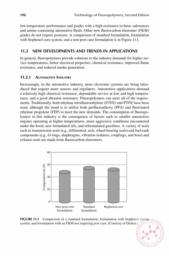
190 Technology of Fluoropolymers, Second Edition
low-temperature performance and grades with a high resistance to basic substances and amine-containing automotive fluids. Other new fluorocarbon elastomer (FKM) grades do not require postcure. A comparison of standard formulation, formulation with bisphenol cure system, and a non-post cure formulation is in Figure 11.1.
11.2 neW DeveloPMenTs anD TRenDs in aPPliCaTions
In general, fluoropolymers provide solutions to the industry demands for higher ser-vice temperatures, better electrical properties, chemical resistance, improved flame resistance, and reduced smoke generation.
11.2.1 automotIVe Industry
Increasingly, in the automotive industry, more electronic systems are being intro-duced that require more sensors and regulators. Automotive applications demand a relatively high chemical resistance, dependable service at low and high tempera-tures, and a good abrasion resistance. Fluoropolymers can meet all of the require-ments. Traditionally, both ethylene tetrafluoroethylene (ETFE) and PTFE have been used, although the trend is to utilize both perfluoroalkoxy (PFA) and fluorinated ethylene propylene (FEP) to meet the new demands. The consumption of fluoropo-lymers in this industry is the consequence of factors such as smaller automotive engines operating at higher temperatures, more aggressive conditions encountered under the hood, new formulated oils, and reformulated gasolines. A variety of seals such as transmission seals (e.g., differential, axle, wheel-bearing seals) and fuel-tank components (e.g., O-rings, diaphragms, vibration isolators, couplings, and hose) and exhaust seals are made from fluorocarbon elastomers.
Standardformulation
Bisphenol cureNon-post cureformulation
Com
pres
sion
Set (
%)
40
30
20
10
0
FiGURe 11.1 Comparison of a standard formulation, formulation with bisphenol curing system, and formulation with an FKM not requiring post cure. (Courtesy of Daikin.)

New Developments and Current Trends 191
11.2.2 aerosPace Industry
In the aerospace industry, too, there is an increasing demand for high-performance electrical insulation with a high degree of fire safety and light weight. Here the trend is for foamed fluoroplastics. FEP is attractive for this purpose. Fuel-tank seals are made predominantly from special perfluoroelastomers.
11.2.3 telecommunIcatIons
In telecommunications similar requirements are placed on insulation materials in addition to low dielectric losses. Thus, even here fluoropolymers are capable of meeting them. Typical applications are insulations and jackets for wires and cables, tubing, piping, and films.
11.2.4 other aPPlIcatIons
In semiconductor equipment the requirements are a very high purity of the mate-rial with little or no outgassing, flexibility, and chemical resistance. Besides ETFE, which has been the mainstay in most of the applications described previously—because of its excellent insulating properties, abrasion resistance, and cut-through resistance—THV and hexafluoropropylene, tetrafluoroethylene, and ethylene (HTE) have also been used successfully. HTE, particularly, has an abrasion resistance and cut-through resistance similar to those of ETFE, but it can be processed on stan-dard extrusion equipment (i.e., that commonly used for polyolefins) and has a higher limiting oxygen index (LOI) than ETFE [23]. Other applications are valves, pumps, wafer-handling equipment, tank linings, windows, films, seals, and gaskets.
PTFE, the largest-volume fluoroplastic, is facing increasing competition from other fluoropolymers. Strongest gains are expected for FEP, which will be driven by accelerating production of semiconductors and wire and cable. PVDF is also expected to post above-average gain mainly from the improvements in semiconduc-tor and wire and cable production, as well as from its increasing use in construction coatings [25]. Additional growth of fluoroplastics is expected due to the growth in fuel cells and lithium and zinc-air batteries [26]. The trends in appliance wiring are toward increasing the service temperature. Other important growth areas of applica-tion are specialty seals in the oil and gas recover industry and flue-duct expansion joints in coal-burning power plants.
11.3 enviRonMenTal issUes ReGaRDinG FlUoRinaTeD sUbsTanCes
A major environmental and health issue is currently the toxicity of PFOA and its salts used in the polymerization process and in processing of the majority of fluo-ropolymers [27,28] and issues involving the use of PTFE coating on cookware and its thermal degradation [29–32]. More on this subject is in Appendix 1.
192 Technology of Fluoropolymers, Second Edition
ReFeRenCes 1. Ebnesajjad, S. Fluoroplastics, Volume 1, Non-Melt Processible Fluoroplastics, Plas-
tics Design Library, Norwich, NY, p.105 (2000). 2. Charpentier, P.A., DeSimone J.M., and Roberts, G.W. in Proceedings of the 51st Cana-
dian Chemical Engineering Conference, Halifax, NS, 2001. 3. Stevens, R.D., Nippon Gomu Kyokaishi (Journal of the Society of Rubber Industry,
Japan), Vol.79, No. 3, p. 153 (2006). 4. Stevens, R.D., Rubber World, Vol. 233, No.5, pp. 23-27 + 42 (2006) 5. Bowers, S. Kautschuk Gummi Kunststoffe, Vol. 55, No. 6, p. 11 (2002) 6. Wille, R.A., Hedhli, L., Durali, M., and Antoun S.Y., U.S. Patent 6,869,997, (2005) to
Arkema, Inc. 7. Dadalas M.C., and Harvey, L.W., U.S. Patent 6,861,466, (2005) to 3M Innovative Prop-
erties Co. 8. Visca, M., Chittofrati, A., Kapeliouchko, V., and Malvasi, M., U.S. Patent 6,878,772,
(2005) to Solvay Solexis SpA. 9. Jones, C.W., and Krakowiak, W.T., U.S. Patent 6,841,594, (January 11, 2005), to E.I. du
Pont de Nemours and Company. 10. Cavanaugh, R.J. et al. US 6,956,078, (Oct. 18, 2005), to E.I. du Pont de Nemours and
Company. 11. Tatemoto, M. in Polymeric Materials Encyclopedia, Vol. 5 (Salamone. J., Ed.), CRC
Press, Boca Raton, FL, p. 3847 (1996). 12. Davis, K.A., and Matyjaszewski, K., Adv. Polym. Sci. 159, p.1 (2002). 13. Ameduri, B, and Boutevin, B., J. Fluorine Chem. 126, p. 225 (2005). 14. Ameduri, B, and Boutevin, B., J. Fluorine Chem. 126, p. 226 (2005). 15. Jankova, K., and Hvilsted, S., J. Fluorine Chem. 126, p. 248 (2005). 16. Tervoort, T., Visjager, J., Graf, B., and Smith, P., Macromolecules 33, p. 6460 (2000). 17. Tervoort, T., Visjager, J., Graf, B., and Smith, P., Journal of Fluorine Chemistry 114 (2),
p. 133 (2002). 18. Smith, P., Visjager, J.F. Bastiaansen C., and Tervoort, T., U.S. Patent 6,737,165, (May
18, 2004), to Omlidon Technologies LLC. 19. Wynne, K., Shenoy, S. Irie, S., Ohsaka, T. and Ohsaka, Y., U.S. Patent 6,960,633, 2005
to Virginia Commonwealth University and Daikin Institute of Advanced Chemistry and Technology (Dai-Act).
20. Menzel, B. and Blanchet, T.A., Wear 258(5-6), p. 93 (2005). 21. Lunkwitz, K., Lappan, U., and U. Scheler, U., J. Fluorine Chem. 125 (6), p. 863
(2004), 22. Jing, N., and Hofmann, G.R.A., U.S. Patent 6,986,947 (2006) to 3M Innovative Prop-
erties Co. 23. Dyneon™ Fluoroplastics Comparison Guide, Dyneon LLC, 2003 24. Polastri, F., and Poggio, T., U.S. Patent 6,924,036 (August 2, 2005) to Solvay Solexis
S.p.A. 25. Fluoropolymers to 2009, Freedonia Report, Freedonia Group, Cleveland, OH, (2005). 26. Fuel Cell Today, October 20, 2005, www.fuelcelltoday. com/ 27. Kennedy, G.L. Buttenhoff, J.L., Olsen, G.W., O’Connor, J.C., Seacat, A.M.., Crit. Rev.
Toxicol. 34 (4) p. 351 (2004). 28. Butenhoff, J. L. and Zobel, L.H., Regul. Toxicol. Pharm. 39 (3) p. 363. (2004) 29. Waritz, R.S. “An Industrial Approach to Evaluation of Pyrolysis and Combustion Haz-
ards”, Environ. Health Perspect. 11, June 1975, p. 197. 30. Williams, S. J., Baker, B.B., and Lee, K.-P., Food Chem.Toxicol. 25 (2) p. 177 (1987). 31. Janofsky, M. New York Times, January 26, 2006, p.16. 32. Eilperin, J. “Harmful Teflon Chemical to Be Eliminated by 2015”, Washington Post,
January 26, 2006, A01.

193
Appendix 1: Environmental Issues Involving Perfluorooctanoic AcidIn the late 1990s, the U.S. Environmental Protection Agency (EPA) received infor-mation indicating that perfluorooctyl sulfonates (PFOSs) were widespread in the blood of the general population and presented concerns for persistence, bioaccu-mulation, and toxicity. Following discussions between the EPA and 3M, the manu-facturer of PFOS, the company terminated production of these chemicals. Findings on PFOS led the EPA to review similar chemicals, including perfluorooctanoic acid (PFOA), starting in 2000, to determine whether they might present concerns similar to those associated with PFOS.
PFOA, sometimes called C8, is used to make almost all types of fluoropolymers, materials that have many industrial applications. The general public is mainly famil-iar with certain consumer products made with fluoropolymers, including nonstick cookware and breathable, all-weather clothing.
The EPA began investigating PFOA because it is very persistent in the environ-ment, it was being found at very low levels both in the environment and in the blood of the general U.S. population, and it caused developmental and other adverse effects in laboratory animals. PFOA may also be a breakdown product of other related chemicals, called fluorinated telomers. Fluorinated telomers are fluoropolymers with an extremely low molecular weight (degree of polymerization between 2 and 5) and are used as surfactants and as surface treatment chemicals in many products, includ-ing fire-fighting foams; personal care and cleaning products; and oil-, stain-, grease-, and water-repellent coatings on carpet, textiles, leather, and paper.
As of now, the information the EPA has available does not indicate that the routine use of household products poses a concern. This agency does not have any indication that the public is being exposed to PFOA through the use of Teflon-coated or other trademarked nonstick cookware. Teflon and other trademarked products are not PFOA. At the present time, the EPA does not believe there is any reason for consumers to stop using any products because of concerns about PFOA. The agency summarized its concerns and identified data gaps and uncertainties about PFOA in a notice published in the Federal Register. Beginning in 2003, the EPA negotiated with multiple parties to produce missing information on PFOA through enforceable consent agreements, memoranda of understanding, and voluntary commitments. Information on these activities is available in the online dockets and on the PFOA meetings pages. In January 2006, the EPA and the eight major companies in the industry created the 2010/2015 Stewardship Program. The companies committed to reduce facility emissions and product content of PFOA and related chemicals by 95% by 2010 and to work toward eliminating emissions and product content by 2015.
194 Technology of Fluoropolymers, Second Edition
CoMPanies PaRTiCiPaTinG in The sTeWaRDshiP PRoGRaM aRe as FolloWs:
3M/Dyneon•Arkema, Inc.•AGC Chemicals/Asahi Glass•Ciba Specialty Chemicals•Clariant Corporation•Daikin•E.I. du Pont de Nemours & Co.•Solvay Solexis•
The purpose of the stewardship program is to improve the understanding of the sources and pathways of exposure. This new information will assist the agency in determining if there are potential risks and what risk management steps may be appropriate. Specifically, the EPA is working with industry and other stakeholders to obtain additional monitoring information on PFOA, exposures resulting from incin-eration or loss from products as they are used over time, and telomer biodegradation as a potential source of PFOA. The agency is developing formal TSCA Section 4 enforceable consent agreements and memoranda of understanding with industry in a public process involving a large number of interested parties and is cooperating on voluntary research activities.
The Society of Plastics Industry, Inc. has created a website (http://www.pfoa-facts.com) as a resource for information and for addressing any questions about PFOA and the products made with it.
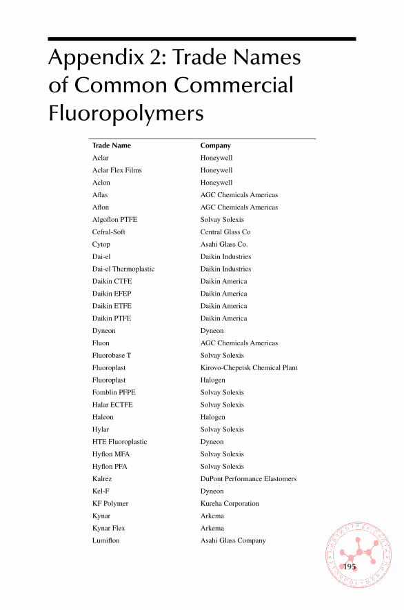
195
Appendix 2: Trade Names of Common Commercial Fluoropolymers
Trade name Company
Aclar Honeywell
Aclar Flex Films Honeywell
Aclon Honeywell
Aflas AGC Chemicals Americas
Aflon AGC Chemicals Americas
Algoflon PTFE Solvay Solexis
Cefral-Soft Central Glass Co
Cytop Asahi Glass Co.
Dai-el Daikin Industries
Dai-el Thermoplastic Daikin Industries
Daikin CTFE Daikin America
Daikin EFEP Daikin America
Daikin ETFE Daikin America
Daikin PTFE Daikin America
Dyneon Dyneon
Fluon AGC Chemicals Americas
Fluorobase T Solvay Solexis
Fluoroplast Kirovo-Chepetsk Chemical Plant
Fluoroplast Halogen
Fomblin PFPE Solvay Solexis
Halar ECTFE Solvay Solexis
Haleon Halogen
Hylar Solvay Solexis
HTE Fluoroplastic Dyneon
Hyflon MFA Solvay Solexis
Hyflon PFA Solvay Solexis
Kalrez DuPont Performance Elastomers
Kel-F Dyneon
KF Polymer Kureha Corporation
Kynar Arkema
Kynar Flex Arkema
Lumiflon Asahi Glass Company

196 Technology of Fluoropolymers, Second Edition
Nafion DuPont Fluoroproducts
Neoflon ETFE Daikin Industries
Neoflon FEP Daikin Industries
Neoflon ETFE Daikin Industries
Neoflon PFA Daikin Industries
Polyflon PTFE Daikin Industries
Polymist Solvay Solexis
SKF Kirovo-Chepetsk Chemical Plant
Solef PVDF Solvay Solexis
Tarflen Zaklady Azotowe
Tecnoflon Solvay Solexis
Tedlar DuPont Fluoroproducts
Teflon DuPont Fluoroproducts
Teflon AF DuPont Fluoroproducts
Teflon FEP DuPont Fluoroproducts
Teflon NXT DuPont Fluoroproducts
Teflon PFA DuPont Fluoroproducts
Tefzel DuPont Fluoroproducts
THV fluoroplastic Dyneon
Viton DuPont Dow Elastomers
Voltalef PCTFE Arkema
Zeffle Daikin Industries
Zonyl micropowders DuPont Fluoroproducts
Note: PTFE, polytetrafluoroethylene; CTFE, chlorotrifluoroethylene; EFEP, per-fluorinated copolymer of ethylene and propylene; ETFE, copolymer of ethylene tetrafluoroethylene; PFPE, perfluorinated polyether; ECTFE, copolymer of ethylene and chlorotrifluoroethylene; HTE, ter-polymer of hexafluoropropylene, tetrafluoroethylene, and ethylene; MFA, copolymer of perfluoromethylvinylether and tetrafluoroethylene; PFA, copolymer of perfluoropropylvinylether and tetrafluoroethylene; FEP, fluorinated ethylene-propylene copolymer; PVDF, poly(vinylidene fluoride); THV, terpolymer of tetrafluoroethylene, hexafluoropropylene, and vinylidene fluoride; PCTFE, poly(chlorotrifluoroethylene).

197
Appendix 3: Acronyms and AbbreviationsAPA advanced polymer architectureAPET amorphous polyethylene terephtalateASTM American Society for Testing and Materials (now ASTM
International)BMI bismaleimideCSM cure site monomerCTFE chlorotrifluoroethyleneDIN Deutsches Institut für Normung eV (German Institute for
Standardization)E ethyleneEB electron beamECTFE copolymer of ethylene and chlorotrifluoroethyleneEFEP ethylene-tetrafluoroethylene-hexafluoropropylene terpolymerETFE copolymer of ethylene and tetrafluoroethyleneFEP fluorinated ethylene propylene (copolymer of tetrafluoroethylene
and hexafluoropropylene)FEPM copolymer of tetrafluoroethylene and propyleneFEVE fluorinated ethylene vinyl etherFFKM perfluoroelastomerFKM fluorocarbon elastomerFMQ fluorosiliconeFPFPE functionalized perfluorinated polyetherFPM ISO designation for fluorocarbon elastomer of the FKM type
(ASTM)FPU fluorinated polyurethaneFTPE fluorinated thermoplastic elastomerFVE fluorovinyl etherFVMQ fluorovinyl polysiloxaneFTIR Fourier transform infrared spectroscopyHDPE high-density polyethyleneHFIB hexafluoroisobutyleneHFP hexafluoropropyleneHPFP hydropentafluoropropyleneHTE (Fluoroplastic) terpolymer of hexafluoropropylene, tetrafluoroethyl-
ene, and ethyleneIPN interpenetrating networkIR infraredISO International Organization for StandardizationLAN local area network
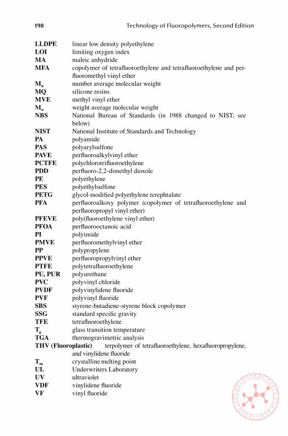
198 Technology of Fluoropolymers, Second Edition
LLDPE linear low density polyethyleneLOI limiting oxygen indexMA maleic anhydrideMFA copolymer of tetrafluoroethylene and tetrafluoroethylene and per-
fluoromethyl vinyl etherMn number average molecular weightMQ silicone resinsMVE methyl vinyl etherMw weight average molecular weightNBS National Bureau of Standards (in 1988 changed to NIST, see
below)NIST National Institute of Standards and TechnologyPA polyamidePAS polyarylsulfonePAVE perfluoroalkylvinyl etherPCTFE polychlorotrifluoroethylenePDD perfluoro-2,2-dimethyl dioxolePE polyethylenePES polyethylsulfonePETG glycol-modified polyethylene terephtalatePFA perfluoroalkoxy polymer (copolymer of tetrafluoroethylene and
perfluoropropyl vinyl ether)PFEVE poly(fluoroethylene vinyl ether)PFOA perfluorooctanoic acidPI polyimidePMVE perfluoromethylvinyl etherPP polypropylenePPVE perfluoropropylvinyl etherPTFE polytetrafluoroethylenePU, PUR polyurethanePVC polyvinyl chloridePVDF polyvinylidene fluoridePVF polyvinyl fluorideSBS styrene-butadiene-styrene block copolymerSSG standard specific gravityTFE tetrafluoroethyleneTg glass transition temperatureTGA thermogravimetric analysisTHV (Fluoroplastic) terpolymer of tetrafluoroethylene, hexafluoropropylene,
and vinylidene fluorideTm crystalline melting pointUL Underwriters LaboratoryUV ultravioletVDF vinylidene fluorideVF vinyl fluoride
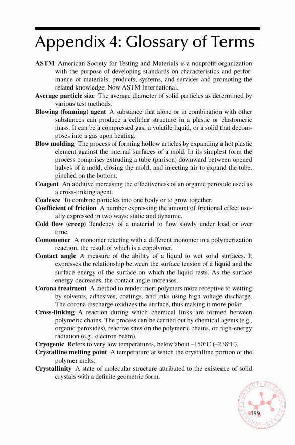
199
Appendix 4: Glossary of TermsASTM American Society for Testing and Materials is a nonprofit organization
with the purpose of developing standards on characteristics and perfor-mance of materials, products, systems, and services and promoting the related knowledge. Now ASTM International.
Average particle size The average diameter of solid particles as determined by various test methods.
Blowing (foaming) agent A substance that alone or in combination with other substances can produce a cellular structure in a plastic or elastomeric mass. It can be a compressed gas, a volatile liquid, or a solid that decom-poses into a gas upon heating.
Blow molding The process of forming hollow articles by expanding a hot plastic element against the internal surfaces of a mold. In its simplest form the process comprises extruding a tube (parison) downward between opened halves of a mold, closing the mold, and injecting air to expand the tube, pinched on the bottom.
Coagent An additive increasing the effectiveness of an organic peroxide used as a cross-linking agent.
Coalesce To combine particles into one body or to grow together.Coefficient of friction A number expressing the amount of frictional effect usu-
ally expressed in two ways: static and dynamic.Cold flow (creep) Tendency of a material to flow slowly under load or over
time.Comonomer A monomer reacting with a different monomer in a polymerization
reaction, the result of which is a copolymer.Contact angle A measure of the ability of a liquid to wet solid surfaces. It
expresses the relationship between the surface tension of a liquid and the surface energy of the surface on which the liquid rests. As the surface energy decreases, the contact angle increases.
Corona treatment A method to render inert polymers more receptive to wetting by solvents, adhesives, coatings, and inks using high voltage discharge. The corona discharge oxidizes the surface, thus making it more polar.
Cross-linking A reaction during which chemical links are formed between polymeric chains. The process can be carried out by chemical agents (e.g., organic peroxides), reactive sites on the polymeric chains, or high-energy radiation (e.g., electron beam).
Cryogenic Refers to very low temperatures, below about –150°C (–238°F).Crystalline melting point A temperature at which the crystalline portion of the
polymer melts.Crystallinity A state of molecular structure attributed to the existence of solid
crystals with a definite geometric form.
200 Technology of Fluoropolymers, Second Edition
Cure A process of changing the properties of a polymer by a chemical reaction (condensation, polymerization, or addition). In elastomers it means mainly cross-linking or vulcanization.
Dielectric constant The ratio of the capacitance assembly of two electrodes separated by a plastic insulating material to its capacitance when the elec-trodes are separated by air only.
Dielectric heating The heating of polymeric materials by dielectric loss in a high-frequency electrostatic field.
Dielectric loss A loss of energy evidenced by the rise in heat of a dielectric placed in an alternating electric field. It is usually observed as a frequency-dependent conductivity.
Dielectric loss factor The product of the dielectric constant and the tangent of the dielectric-loss angle for a material.
Dielectric loss tangent The difference between 90° and the dielectric phase angle for a material.
Dielectric strength Ability of a material to resist the passage of electric current.
Differential scanning calorimetry (DSC) The method to measure the heat flow to a sample as a function of temperature. It is used to measure, for example, specific heats, glass transition temperatures, melting points, melting pro-files, degree of crystallinity, degree of cure, and purity.
Elasticity The ability of a material to quickly recover its original dimensions after removal of the load that has caused the deformation.
Elastomer A polymeric substance with elastic properties. Such material can be stretched repeatedly at room temperature to at least twice its original length and upon immediate release of the stress will return with force to its approximate original length.
Electron beam (EB) cure A process using high-energy (accelerated) electrons to promote reactions in a polymeric material (cross-linking, polymeriza-tion). The reaction is instantaneous. The voltage range used in this process is typically from hundreds of kilovolts to several megavolts.
ETFE Copolymer of ethylene and tetrafluoroethylene noted for an exceptional chemical resistance, toughness, and abrasion resistance.
FEP Fluorinated ethylene propylene having excellent nonstick and nonwetting properties.
Film formation A process in which a film is formed after solvent or water is removed, or due to a chemical reaction.
Friction, dynamic Resistance to continued motion between two surfaces, also known as sliding friction.
Friction, static Resistance to initial motion between two surfaces.Fuel cell An electrochemical energy conversion device. It produces electricity
from various external quantities of fuel (on the anode side) and oxidant (on the cathode side). These react in the presence of an electrolyte. Fuel cells are different from batteries in that they consume reactant, which must be replenished, while batteries store electrical energy chemically in a closed system
Appendix 4: Glossary of Terms 201
Fusion A process in which a continuous film or a solid body is formed by melt-ing and flowing (coalesce) of polymer particles.
Glass transition temperature (Tg) A point below which an amorphous polymer behaves as glass does: It is very strong and rigid but brittle. Above this temperature it exhibits leathery or rubbery behavior.
Heat buildup Heat generated within a polymeric material due to its viscoelastic-ity (hysteresis) and friction. It occurs during processing (mainly friction and kneading) and in service (mainly repeated cycling).
HFP Hexafluoropropylene, a monomer used for the production of fluorinated ethylene propylene (FEP) and other copolymers (e.g., THV thermoplastic) and of fluorinated elastomers.
Hysteresis Incomplete recovery of strain during unloading cycle due to energy consumption. This energy is converted from mechanical to frictional energy (heat).
Ionomer resins Modified polymers obtained by heating and pressing certain polymers containing carboxylic groups in the presence of metallic ions.
Laminate A product made by bonding together one or more layers of material or materials. It is frequently assembled by simultaneous application of heat and pressure. A laminate may consist of coated fabrics or of metals or films or may be different combinations of these.
Latex A stable dispersion of a polymeric substance (most frequently of an elas-tomer) in an essentially aqueous medium.
Methylfluoroalkoxy resin (MFA) A copolymer of tetrafluoroethylene (TFE) and perfluoro(methylvinyl resin ether) with properties similar to perfluo-roalkoxy (PFA); it has about 20°C lower melting temperature than PFA.
Modified polytetrafluoroethylene (PTFE) Copolymer of tetrafluoroethylene (TFE) and of a small amount (less than 1%) of other perfluorinated mono-mer (e.g., perfluoroalkoxy monomer) exhibiting considerably improved physical properties, moldability, and much lower microporosity.
Monomer A relatively simple compound, usually containing carbon and of low molecular weight, which can react to form a polymer by combination with itself or with other similar molecules or compounds.
Perfluorinated resin A polymer consisting of monomers where all main chain carbons are combined with fluorine atoms only (e.g., tetrafluoroethylene [TFE], hexafluoropropylene [HFP]).
Perfluoroalkoxy resin (PFA) Copolymer of tetrafluoroethylene (TFE) with perfluoro(propylvinyl ether), an engineering thermoplastic characterized by excellent thermal stability, release properties, low friction and tough-ness. Its performance is comparable to polytetrafluoroethylene (PTFE) with the difference that it is melt processible.
Perfluoromethylvinyl ether (PMVE) A monomer used for the production of methylfluoroalkoxy (MFA).
Perfluoropropylvinyl ether (PPVE) Monomer used for the production of per-fluoroalkoxy (PFA).
Piezoelectricity The ability of some materials (notably crystals and certain ceramics) to generate an electric potential in response to applied mechani-

202 Technology of Fluoropolymers, Second Edition
cal stress. This may take the form of a separation of electric charge across the crystal lattice. If the material is not short-circuited, the applied charge induces a voltage across the material. The effect finds useful applications such as the production and detection of sound, generation of high voltages, electronic frequency generation, microbalances, and ultrafine focusing of optical assemblies.
Polymer fume fever An illness characterized by temporary flu-like symptoms caused by inhaling the products released during the decomposition of fluoropolymers, mainly polytetrafluoroethylene (PTFE). Tobacco smoke enhances the severity of this condition.
Postcure A second cure at high temperatures enhancing some properties and or removing decomposition products of the primary reaction.
Prorad Radiation promoter, a compound promoting or enhancing the cross-link-ing reaction by high-energy (ionizing) radiation.
Pyroelectricity The ability of certain materials to generate an electrical poten-tial when they are heated or cooled. As a result of this change in tem-perature, positive and negative charges move to opposite ends through migration (i.e., the material becomes polarized), and, hence, an electrical potential is established.
Scorch Premature incipient vulcanization of a rubber compound.Scorch, Mooney The time to incipient of a rubber compound when tested in the
Mooney shearing disc viscometer under specific conditions.Sintering A process in which polytetrafluoroethylene (PTFE) particles are
heated above the melting point; they soften and coalesce, thus forming a continuous film or a solid body.
Substrate Any surface to be coated by a coating or bonded by an adhesive.Surface resistance The surface resistance between two electrodes in contact with
a material is the ratio of the voltage applied to the electrodes to that portion of the current between them, which flows through the surface layers.
Surfactant A widely used contraction of surface active agent, a compound that alters surface tension of a liquid in which it is dissolved.
Telomer Its original meaning is in polymer science, to refer to an extremely small polymer—one whose degree of polymerization is between 2 and 5.
Terpolymer The product of simultaneous polymerization of three differ-ent monomers, or of grafting of one monomer to the copolymer of two monomers.
Tetrafluoroethylene (TFE) A perfluorinated monomer used as a feedstock for the production of polytetrafluoroethylene (PTFE) and as a comonomer for the production of a variety of other fluoropolymers.
Thermoforming A process of forming a plastic film or sheet into a three-dimensional shape by clamping it, heating it, and then applying a dif-ferential pressure to make the film or sheet conform to the shape of the mold.
Thermogravimetric analysis (TGA) A widely used method to determine weight change upon heating, such as decomposition and amount of volatile com-ponents, including moisture.

Appendix 4: Glossary of Terms 203
THV (fluoroplastic) A terpolymer of tetrafluoroethylene (TFE), hexafluoropro-pylene (HFP), and vinylidene fluoride (VDF).
Viscoelasticity The tendency of polymers to respond to stress as if they were a combination of elastic solids and viscous fluids.
Viscosifying agent A substance used to increase the viscosity of a liquid mainly by swelling.
Viscosity The property of resistance of flow exhibited within the body of mate-rial. Units of viscosity are Pascal (traditional) and Pa.sec (SI). Conversion: 10 P = 1 Pa.s or 1 cP = 1m Pa.s.
Viscosity, Mooney A measure of the viscosity of a rubber or elastomer deter-mined in a Mooney shearing rotation disc viscometer (ASTM D1646).
Volume resistivity The electrical resistance between opposite sides of a cube.

205
Appendix 5: Fluoropolymer Bibliography
booKs
Ameduri, B. and Boutevin, B., Well-Architectured Fluoropolymers: Synthesis, Properties and Applications, Elsevier B.V., Amsterdam, 2004.
Drobny, J. G., Fluoroplastics, Vol. 16, Number 4, Review Report 184, Rapra Technology Ltd., Shawbury, Shrewsbury, Shropshire, UK, Report 184, 2006.
Drobny, J. G., Technology of Fluoropolymers, CRC Press, Boca Raton, FL, 2001.Ebnesajjad, S., Fluoroplastics, Vol. 1, Non-Melt Processible Fluoropolymers, The Definitive
User’s Guide and Databook, Plastics Design Library, William Andrew Publishing, Norwich, NY, 2000.
Ebnesajjad, S., Fluoroplastics, Vol. 2, Melt Processible Fluoropolymers, The Definitive User’s Guide and Databook, Plastics Design Library, William Andrew Publishing, Norwich, NY, 2003.
Ebnesajjad, S. and Khaladkar, P. R., Fluoropolymer Applications in Chemical Processing Industries, The Definitive User’s Guide and Databook, Plastics Design Library, Wil-liam Andrew Publishing, Norwich, NY, 2005.
Grot, W., Fluorinated Ionomers, Plastics Design Library, William Andrew Publishing, Nor-wich, NY, 2007.
Hougham, G., Cassidy, P., Johns, K., and Davidson, T. (Eds.), Fluoropolymers 1, Synthesis, Kluver Academic/Plenum Publishers, New York, 1999.
Hougham, G., Cassidy, P., Johns, K., and Davidson, T. (Eds.), Fluoropolymers 2, Properties, Kluver Academic/Plenum Publishers, New York, 1999.
Moore, A. L., Handbook of Fluoroelastomers, The Definitive User’s Guide and Databook, Plastics Design Library, William Andrew Publishing, Norwich, NY, 2005.
Scheirs, J. (Ed.), Modern Fluoropolymers, John Wiley & Sons Ltd., Chichester, UK, 1997.Stacey, M., Tatlow, J. C., and Sharpe, A. G. (Eds.), Advances in Fluorine Chemistry, Butter-
worth & Co., Ltd. Kent, UK, 1963.Wall, L. J. (Ed.), Fluoropolymers, Wiley-Interscience, New York, 1972.
MaGazines
Journal of Fluorine Chemistry, published monthly by Elsevier Science (Amsterdam), con-tains original papers and short communications describing both pure and applied research on the chemistry and applications of fluorine and of compounds where fluo-rine exercises significant effects. The journal covers inorganic, organic, organometallic and physical chemistry and also includes papers on biochemistry and environmental industrial chemistry.
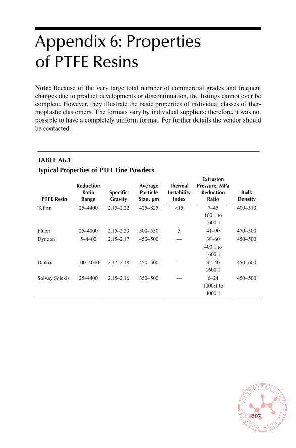
207
Appendix 6: Properties of PTFE ResinsNote: Because of the very large total number of commercial grades and frequent changes due to product developments or discontinuation, the listings cannot ever be complete. However, they illustrate the basic properties of individual classes of ther-moplastic elastomers. The formats vary by individual suppliers; therefore, it was not possible to have a completely uniform format. For further details the vendor should be contacted.
Table a6.1Typical Properties of PTFe Fine Powders
PTFe Resin
Reduction Ratio Range
specific Gravity
average Particle size, μm
Thermal instability
index
extrusion Pressure, MPa
Reduction Ratio
bulk Density
Teflon 25–4400 2.15–2.22 425–825 <15 7–45 100:1 to 1600:1
400–510
Fluon 25–4000 2.15–2.20 500–550 5 41–90 470–500
Dyneon 5–4400 2.15–2.17 450–500 — 38–60 400:1 to 1600:1
450–500
Daikin 100–4000 2.17–2.18 450–500 — 35–40 1600:1
450–600
Solvay Solexis 25–4400 2.15–2.16 350–500 — 6–24 1000:1 to
4000:1
450–500
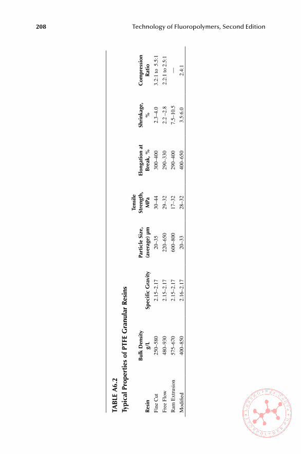
208 Technology of Fluoropolymers, Second Edition
Tab
le a
6.2
Ty
pica
l Pro
pert
ies
of P
TFe
Gra
nula
r R
esin
s
Res
inb
ulk
Den
sity
g/l
spec
ific
Gra
vity
Part
icle
siz
e,
(ave
rage
) μm
Tens
ile
stre
ngth
, M
Pael
onga
tion
at
bre
ak, %
shri
nkag
e,%
Com
pres
sion
R
atio
Fine
Cut
250–
580
2.15
–2.1
720
–35
30–4
430
0–40
02.
3–4.
03.
2:1
to 5
.5:1
Free
Flo
w48
0–93
02.
15–2
.17
220–
650
29–3
229
0–33
02.
2 –2
.82.
2:1
to 2
.5:1
Ram
Ext
rusi
on57
5–67
02.
15–2
.17
600–
800
17–3
229
0–40
07.
5–10
.5—
Mod
ified
400–
850
2.16
–2.1
720
–33
28–3
240
0–65
03.
5:6.
02.
4:1

Appendix 6: Properties of PTFE Resins 209
Table a6.3
examples of selected PTFe Micropowders (nominal values)
Productaverage bulk Density, g/l
average Particle size,
μm
specific surface area,
m2/gMelting Peak
Temp, °C
Algoflon® L100 350 20 max 20 min 323–328
L101–1 300 3 14 min 328–332
L101–X 300 7 max 7.5 min 328–332
L203 310 6 max 70.5 min 328–332
L206 330 7 max 7.5 min 328–332
Dyneon™
Polymer Additive
PA 5951 350 6 10 —
PA 5952 — 15 2 325
PA 5953 400 8 2 —
PA 5954 280 4 — —
PA 5955 280 — 17 —
PA 5956 250 6 — —
Fluon®
PTFE L150J 380 9 1.3 325
L169J 370 13 2 325
L170J 560 — 8.2 332
L173J 300 7 8.2 330
Polyflon®
Low Polymer L–2 370 4 9 330
L–5 420 7 11 327
L–5F 420 5 11 327
LDW–40* — 0.18 — 330
Polymist® F5 400 5.5 3 326
F5A 400 4.0 3 326
F5A EX 500 12 3 328
F510 475 14 3 331
XPA213 375 3.5 3 326
XPP–510 275–500 3.0–4.5 2–3 322–326
XPP–513 400–600 11–15 2–3 319–327
XPP–514 400–600 10–12 2–3 319–327
XPP–518 — 2.75–3.25 2–3 323–328
XPP–519 325–525 2.75–3.25 2–3 319–325
XPP–525 275–500 3.0–4.5 2–3 319–327
XPP–529 — 2.75–3.25 2–3 323–328
XPP–530 350–600 3.5–4.0 2–3 319–327
(continued)

210 Technology of Fluoropolymers, Second Edition
Table a6.3
examples of selected PTFe Micropowders (nominal values)
Productaverage bulk Density, g/l
average Particle size,
μm
specific surface area,
m2/gMelting Peak
Temp, °C
XPP–535 350–600 3.5–4.0 2–3 319–327
XPP–538 300–550 4–5 2–3 318–328
XPP–539 300–550 2.0–3.0 2–3 318–328
XPP–540 250–450 12–15 2–3 330–334
Zonyl® MP1000 500 12 5–10 —
MP1100 300 4 5–10 325±5
MP1150 450 36 10 325±5
MP1200 450 3 1.5–30 325±5
MP1300 425 3 1.5–3.0 325±5
MP1400 425 10 1.5–3.0 325±5
MP1500 375 20 8–12 325±5
MP1600N 350 12 8–12 325±5
TE–3808 225–600 5–20 4.6–15 —
TE–3887*
*Aqueous dispersion of PTFE micropowderSolids content: 60% PTFE by weightDispersion particle size: 0.210 μmpH of dispersion: 10.5Density of dispersion at 60% solids: 1.50

Appendix 6: Properties of PTFE Resins 211
Tab
le a
6.4
Typi
cal P
rope
rtie
s of
PTF
e a
queo
us D
ispe
rsio
ns (
nom
inal
val
ues)
Dis
pers
ion
PTFe
Res
in
solid
s, w
t.
%su
rfac
tant
, w
t.
%
surf
ace
Tens
ion,
m
n/m
spec
ific
Gra
vity
ave
rage
Pa
rtic
le
size
, μm
phv
isco
sity
m
Pa.s
Mel
ting
Poi
nt, °
C (
°F)
init
ial
seco
ndTe
flon®
PT
FE 3
060
——
1.5
0.22
9.5
2033
7 (6
39)
327
(621
)Te
flon®
PT
FE 3
0B60
——
1.5
0.22
9.5
2033
7 (6
39)
327
(621
)Te
flon®
PT
FE 3
05A
60—
—1.
50.
229.
520
337
(639
)32
7 (6
21)
Teflo
n® P
TFE
307
A60
——
1.5
0.16
9.5
2033
7 (6
39)
327
(621
)Te
flon®
PT
FE 3
03A
60—
—1.
50.
229.
520
337
(639
)32
7 (6
21)
Teflo
n® P
TFE
B61
*1.
440.
228.
5—
337
(639
)32
7 (6
21)
Teflo
n® P
TFE
35
352.
5—
1.24
0.05
–0.5
——
——
Teflo
n® P
TFE
K–2
033
——
1.22
0.22
9.5
1533
7 (6
39)
327
(621
)Te
flon®
PT
FE T
E–3
823
606
271.
527
0 nm
1020
344
(653
)32
7 (6
21)
Fluo
n® P
TFE
XA
D91
1*60
533
1.52
0.25
9.5
25—
—Fl
uon®
PT
FE X
AD
912*
*55
9.5
321.
460.
259.
525
——
Fluo
n® P
TFE
XA
D 9
38**
605
331.
520.
309.
525
——
Fluo
n® P
TFE
AD
160
535
1.52
0.25
9.5
20—
—Fl
uon®
PT
FE A
D63
957
533
1.49
0.25
9.5
25—
—Fl
uon®
PT
FE A
D93
660
535
1.52
0.30
9.5
25—
—A
lgofl
on®
D 1
122X
603.
5—
1.51
0.24
>9
20—
—A
lgofl
on®
D 1
214X
***
603.
5—
1.51
0.24
>9
20—
—A
lgofl
on®
D 3
015
593.
5—
1.49
0.24
>9
20—
—A
lgofl
on®
D 3
112
593.
5—
1.49
0.24
>9
20—
—A
lgofl
on®
D 3
211*
**59
3.5
—1.
490.
24>
920
——
Alg
oflon
® D
3314
58.5
4.2
—1.
490.
24>
920
——
Alg
oflon
® D
332
0X**
58.5
3.5
—1.
490.
24>
920
— —
*Act
ive
ingr
edie
nts
**G
reen
sur
fact
ant
***A
PFO
con
tent
(on
the
mix
ture
) <
50pp
m
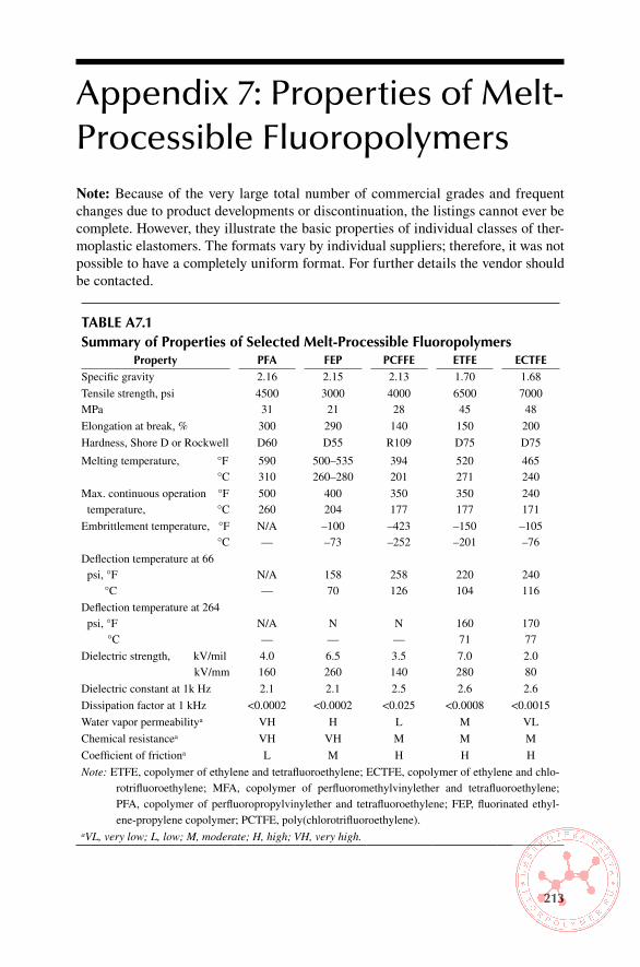
213
Appendix 7: Properties of Melt-Processible FluoropolymersNote: Because of the very large total number of commercial grades and frequent changes due to product developments or discontinuation, the listings cannot ever be complete. However, they illustrate the basic properties of individual classes of ther-moplastic elastomers. The formats vary by individual suppliers; therefore, it was not possible to have a completely uniform format. For further details the vendor should be contacted.
Table a7.1summary of Properties of selected Melt-Processible Fluoropolymers
Property PFa FeP PCFFe eTFe eCTFeSpecific gravity 2.16 2.15 2.13 1.70 1.68
Tensile strength, psiMPa
450031
300021
400028
650045
700048
Elongation at break, % 300 290 140 150 200
Hardness, Shore D or Rockwell D60 D55 R109 D75 D75
Melting temperature, °F °C
590310
500–535260–280
394201
520271
465240
Max. continuous operation °F temperature, °C
500260
400204
350177
350177
240171
Embrittlement temperature, °F °C
N/A—
–100–73
–423–252
–150–201
–105–76
Deflection temperature at 66 psi, °F
°CN/A—
15870
258126
220104
240116
Deflection temperature at 264 psi, °F
°CN/A—
N—
N—
16071
17077
Dielectric strength, kV/milkV/mm
4.0160
6.5260
3.5140
7.0280
2.080
Dielectric constant at 1k Hz 2.1 2.1 2.5 2.6 2.6
Dissipation factor at 1 kHz <0.0002 <0.0002 <0.025 <0.0008 <0.0015
Water vapor permeabilitya VH H L M VL
Chemical resistancea VH VH M M M
Coefficient of frictiona L M H H H
Note: ETFE, copolymer of ethylene and tetrafluoroethylene; ECTFE, copolymer of ethylene and chlo-rotrifluoroethylene; MFA, copolymer of perfluoromethylvinylether and tetrafluoroethylene; PFA, copolymer of perfluoropropylvinylether and tetrafluoroethylene; FEP, fluorinated ethyl-ene-propylene copolymer; PCTFE, poly(chlorotrifluoroethylene).
aVL, very low; L, low; M, moderate; H, high; VH, very high.

214 Technology of Fluoropolymers, Second Edition
Table a7.2FeP aqueous Dispersions
ProductFeP solids,
%wtspecific Gravity
average particle size, μm ph
viscosity at 25°C, mPa.s
Melting, Peak Temperature
°C (°F)
Teflon FEP 121A 54 1.41 0.18 > 9.5 25 260 (500)
Neoflon ND-1 FEP 50 1.41 — — 0.3 —
Neoflon ND-2 FEP 23 1.30 — — 4–8 —
Neoflon ND-4 FEP 40 1.40 — — 3–7 —
Neoflon ND-4 GY FEP
40 1.40 — — 3–7 —
Note: FEP, fluorinated ethylene propylene.
Table a7.3PFa/MFa aqueous Dispersions
ProductPFa solids,
%wtspecific Gravity
average particle size, μm ph
Melt Flow Rate, g/10
min
Melting, Peak Temperature,
°C (°F)
Teflon PFA 60 1.5 0.20 > 9.5 1–3 305 (581)
Dyneon PFA 6900N
50 1.43 — < 7 15 310 (590)
Hyflon D 5010X (MFA)
55 1.41 0.18 > 9 — —
Note: PFA, perfluoroalkoxy resin; MFA, methylfluoroalkoxy resin.
Table a7.4Properties of Dyneon Thv 340C Fluoroplastic (nominal values)Property Test Methods value
Solids content, % by wt. ISO 12086/ASTM D4441 34
pH ISO 1148/ASTM E70 7
Melting point, °C DIN ISO 3146/ASTM D4591 145
Melt index, g/10 min DIN 53735/ASTM D1238 40
Average particle size, nm ISO 13321 90
Density, g/cm3 ASTM D1298 1.23
Viscosity (D = 210 s-1) DIN 54453 20
Surfactant type — Ionic
Source: Dyneon Fluoroplastics, Product Comparison Guide, 98-0504-1501-1, Dyneon, LLC, 2003 (With permission).

Appendix 7: Properties of Melt-Proccessible Fluoropolymers 215
Table a7.5Properties of Kynar aquatec RC 10,206 (nominal values)
Property value
Solids content, % by weight 47
pH 8.2
Wet density, g/mL 1.2
MFFT, °C (°F) 27 (81)
Fluoropolymer/acrylic resin ratio 70:30
VOC, as supplied, % < 1
Viscosity Brookfield at RT (30 s-1) 100
Note: MFFT, minimum film-forming temperature.
Source: Arkema, Inc., 2008 (With permission).
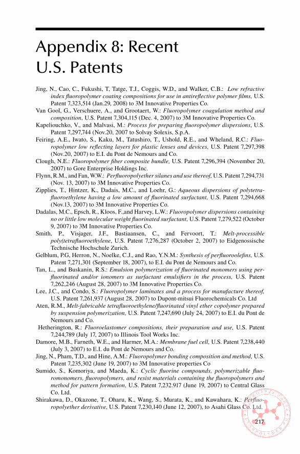
217
Appendix 8: Recent U.S. PatentsJing, N., Cao, C., Fukushi, T, Tatge, T.J., Coggis, W.D., and Walker, C.B.: Low refractive
index fluoropolymer coating compositions for use in antireflective polymer films, U.S. Patent 7,323,514 (Jan.29, 2008) to 3M Innovative Properties Co.
Van Gool, G., Verschuere, A., and Grootaert, W.: Fluoropolymer coagulation method and composition, U.S. Patent 7,304,115 (Dec. 4, 2007) to 3M Innovative Properties Co.
Kapeliouchko, V., and Malvasi, M.: Process for preparing fluoropolymer dispersions, U.S. Patent 7,297,744 (Nov.20, 2007 to Solvay Solexis, S.p.A.
Feiring, A.E., Iwato, S., Kaku, M., Tatushiro, T., Ushold, R.E., and Wheland, R.C.: Fluo-ropolymer low reflecting layers for plastic lenses and devices, U.S. Patent 7,297,398 (Nov.20, 2007) to E.I. du Pont de Nemours and Co.
Clough, N.E.: Fluoropolymer fiber composite bundle, U.S. Patent 7,296,394 (November 20, 2007) to Gore Enterprise Holdings Inc.
Flynn, R.M., and Fan, W.W.: Perfluoropolyether silanes and use thereof, U.S. Patent 7,294,731 (Nov. 13, 2007) to 3M Innovative Properties Co.
Zipplies, T., Hintzer, K., Dadais, M.C., and Loehr, G.: Aqueous dispersions of polytetra-fluoroethylene having a low amount of fluorinated surfactant, U.S. Patent 7,294,668 (Nov.13, 2007) to 3M Innovative Properties Co.
Dadalas, M.C., Epsch, R., Kloos, F.,and Harvey, L.W.: Fluoropolymer dispersions containing no or little low molecular weight fluorinated surfactant, U.S. Patent 7,279,522 (October 9, 2007) to 3M Innovative Properties Co.
Smith, P., Visjager, J.F., Bastiaansen, C., and Fervoort, T.: Melt-processible poly(tetrafluoroethylene, U.S. Patent 7,276,287 (October 2, 2007) to Eidgenossische Technische Hochschule Zurich.
Gelblum, P.G, Herron, N., Noelke, C.J., and Rao, Y.N.M.: Synthesis of perfluoroolefins, U.S. Patent 7,271,301 (September 18, 2007), to E.I. du Pont de Nemours and Co.
Tan, L., and Buskanin, R.S.: Emulsion polymerization of fluorinated monomers using per-fluorinated and/or ionomers as surfactant emulsifiers in the process, U.S. Patent 7,262,246 (August 28, 2007) to 3M Innovative Properties Co.
Lee, J.C., and Condo, S.: Fluoropolymer laminates and a process for manufacture thereof, U.S. Patent 7,261,937 (August 28, 2007) to Dupont-mitsui Fluorochemicals Co. Ltd
Aten, R.M., Melt-fabricable tetrafluoroethylene/fluorinated vinyl ether copolymer prepared by suspension polymerization, U.S. Patent 7,247,690 (July 24, 2007) to E.I. du Pont de Nemours and Co.
Hetherington, R.: Fluoroelastomer compositions, their preparation and use, U.S. Patent 7,244,789 (July 17, 2007) to Illinois Tool Works Inc.
Damore, M.B., Farneth, W.E., and Harmer, M.A.: Membrane fuel cell, U.S. Patent 7,238,440 (July 3, 2007) to E.I. du Pont de Nemours and Co.
Jing, N., Pham, T.D., and Hine, A.M.: Fluoropolymer bonding composition and method, U.S. Patent 7,235,302 (June 19, 2007) to 3M Innovative properties Co
Sumido, S., Komoriya, and Maeda, K.: Cyclic fluorine compounds, polymerizable fluo-romonomers, fluoropolymers, and resist materials containing the fluoropolymers and method for pattern formation, U.S. Patent 7,232.917 (June 19, 2007) to Central Glass Co. Ltd.
Shirakawa, D., Okazone, T., Oharu, K., Wang, S., Murata, K., and Kawahara, K.: Perfluo-ropolyether derivative, U.S. Patent 7,230,140 (June 12, 2007), to Asahi Glass Co. Ltd.

218 Technology of Fluoropolymers, Second Edition
Park, E.H.: Branched chain fluoropolymers, U.S. Patent 7,230,038 (June 12, 2007) to Freudenberg-NOK General Partnership.
Udagawa, A., and Oshima, A.: Radiation-modified poly(tetrafluoroethylene) resin feeds and process for producing the same, U.S. Patent 7,220,799 (May 22, 2007) to Japan Atomic Energy Research Institute.
Finn, P.J., and Dudek, D.M.: Wear resistant fluoropolymer, U.S. Patent 7, 214,423 (May 8, 2007), to Xerox Co
Grootaert, W.M.A., Kolb. R.E., and Hintzer, K.: Fluoropolymer curing system, U.S. Patent 7,208,553 (April 24, 2007) to 3M Innovative Properties Co.
Funaki, A., Sumi, N., and Nishi, E.: Fluorocopolymer, U.S. Patent 7,205,367 (April 17, 2007) to UBE Industries Ltd. and Asahi Glass Co. Ltd.
Jing, N., Pham, T.D., and Hine, A.M. : Fluoropolymer composition and method, U.S. Patent 7,175,733 (Feruary 13, 2007), to 3M Innovative Properties Co.:
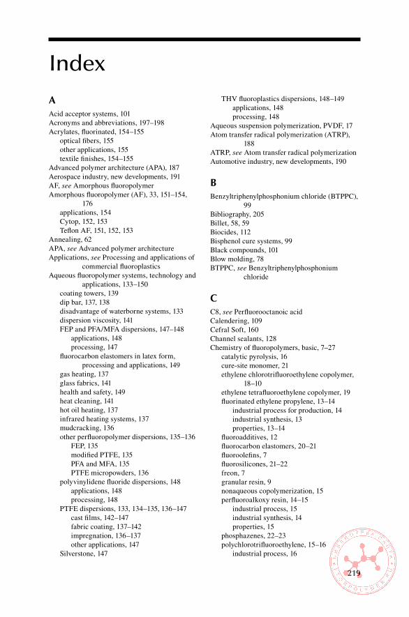
219
Index
aAcid acceptor systems, 101Acronyms and abbreviations, 197–198Acrylates, fluorinated, 154–155 optical fibers, 155 other applications, 155 textile finishes, 154–155Advanced polymer architecture (APA), 187Aerospace industry, new developments, 191AF, see Amorphous fluoropolymerAmorphous fluoropolymer (AF), 33, 151–154,
176 applications, 154 Cytop, 152, 153 Teflon AF, 151, 152, 153Annealing, 62APA, see Advanced polymer architectureApplications, see Processing and applications of
commercial fluoroplasticsAqueous fluoropolymer systems, technology and
applications, 133–150 coating towers, 139 dip bar, 137, 138 disadvantage of waterborne systems, 133 dispersion viscosity, 141 FEP and PFA/MFA dispersions, 147–148 applications, 148 processing, 147 fluorocarbon elastomers in latex form,
processing and applications, 149 gas heating, 137 glass fabrics, 141 health and safety, 149 heat cleaning, 141 hot oil heating, 137 infrared heating systems, 137 mudcracking, 136 other perfluoropolymer dispersions, 135–136 FEP, 135 modified PTFE, 135 PFA and MFA, 135 PTFE micropowders, 136 polyvinylidene fluoride dispersions, 148 applications, 148 processing, 148 PTFE dispersions, 133, 134–135, 136–147 cast films, 142–147 fabric coating, 137–142 impregnation, 136–137 other applications, 147 Silverstone, 147
THV fluoroplastics dispersions, 148–149 applications, 148 processing, 148Aqueous suspension polymerization, PVDF, 17Atom transfer radical polymerization (ATRP),
188ATRP, see Atom transfer radical polymerizationAutomotive industry, new developments, 190
bBenzyltriphenylphosphonium chloride (BTPPC),
99Bibliography, 205Billet, 58, 59Biocides, 112Bisphenol cure systems, 99Black compounds, 101Blow molding, 78BTPPC, see Benzyltriphenylphosphonium
chloride
CC8, see Perfluorooctanoic acidCalendering, 109Cefral Soft, 160Channel sealants, 128Chemistry of fluoropolymers, basic, 7–27 catalytic pyrolysis, 16 cure-site monomer, 21 ethylene chlorotrifluoroethylene copolymer,
18–10 ethylene tetrafluoroethylene copolymer, 19 fluorinated ethylene propylene, 13–14 industrial process for production, 14 industrial synthesis, 13 properties, 13–14 fluoroadditives, 12 fluorocarbon elastomers, 20–21 fluoroolefins, 7 fluorosilicones, 21–22 freon, 7 granular resin, 9 nonaqueous copolymerization, 15 perfluoroalkoxy resin, 14–15 industrial process, 15 industrial synthesis, 14 properties, 15 phosphazenes, 22–23 polychlorotrifluoroethylene, 15–16 industrial process, 16

220 Index
industrial synthesis, 15 properties, 15–16 polytetrafluoroethylene, 7–13 equipment used in handling, 8 industrial synthesis, 7–8 polymerization, 9–13 properties, 8–9 superheated steam as diluent, 8 uses, 9 polyvinyl fluoride, 18 industrial process, 18 industrial synthesis, 18 polyvinylidene fluoride, 16–17 catalytic pyrolysis, 16 industrial process, 17 industrial synthesis, 16 properties, 17 reduction–activation systems, 9 terpolymers of HFP, TFE, and ethylene, 20 terpolymers of TFE, HFP, and VDF, 19Chloralkali cells, 163Chlorotrifluoroethylene (CTFE), 7, 31, 188 properties, 15–16 synthesis, commercial process, 15Chlorotrifluoroethylene and vinyl ether
copolymers, 162–163Coining, 65Compression molding, 110Continuous upper service temperature, ETFE, 43Core-shell polymers, 11CSM, see Cure-site monomerCTFE, see ChlorotrifluoroethyleneCuratives, 103Cure-site monomer (CSM), 21, 98Cytop, 152, 176
DDioctyl phtalate (DOP), 103Dip bar, 137, 138Disposal, see Safety, hygiene, and disposal of
fluoropolymersDissipation factor, 38DOP, see Dioctyl phtalateDurometer hardness, 126Dwell time, 60
eECTFE copolymer, see Ethylene
chlorotrifluoroethylene copolymerElastomers, see Fluorocarbon elastomersElectron beam process, 12Electron spin resonance (ESR) spectroscopy, 177Elongation values, 32Emulsion polymerization, PVDF, 17Environment effects, see Heat, radiation, and
environment effects on fluoropolymers
EPA, see U.S. Environmental Protection AgencyESR spectroscopy, see Electron spin resonance
spectroscopyETFE copolymer, see Ethylene
tetrafluoroethylene copolymerEthylene chlorotrifluoroethylene (ECTFE)
copolymer, 18–19, 48 copolymerization, 19 industrial process, 18Ethylene tetrafluoroethylene (ETFE) copolymer,
19, 43–44, 133 automotive applications, 190 chemical properties, 43 coatings, 76 continuous upper service temperature, 43 cross-linking, 175 dielectric properties, 43 gas-injection foaming process, 81 irradiation, 43 mechanical properties, 43 molded parts, 80 structure, 43 thermal stability, 44 welding, 76
FFDA, see U.S. Food and Drug AdministrationFEP, see Fluorinated ethylene propyleneFEVE, see Fluorinated ethylene vinyl etherFKM, see Fluorocarbon elastomersFluorinated ethylene propylene (FEP), 13, 30, 74 automotive applications, 190 degradation by radiation, 174 dispersions, 135 electrical properties, 40 extruded pipes, 79 gas permeation, 49 industrial process, 14 industrial synthesis, 13 mechanical properties, 39 properties, 13–14 reduced creep, 39 static friction, 39 thermal stability, 172 vibration damping, 39Fluorinated ethylene vinyl ether (FEVE), 157Fluorinated thermoplastic elastomers (FTPEs),
160, see also Thermoplastic elastomers, fluorinated, applications
Fluoroadditives, 12, 164, see also Polytetrafluoroethylene micropowders
Fluorocarbon elastomers, 20–21, 93–132 acid acceptors, 102 applications of FFKM, 120–121 applications of FKM, 117–120 aerospace and military applications,
119–120

Index 221
automotive applications, 117–119 chemical and petrochemical applications,
120 coatings and sealants, 122 other industrial applications, 120 biocides, 112 bisphenol cure systems, 99 black compounds, 101 brittle points, 114 calendering, 109 channel sealants, 128 chemical resistance, 96, 125 closed cell sponge, 107 commercially available, 95 comparison, 113 compounds based on TFE/P elastomer, 107 compression molding, 110 cross-linking chemistry, 98–101 by free radical mechanism, 100 by ionic mechanism, 98–100 by ionizing radiation, 100–101 cured, physical and mechanical properties,
113–117 compression set resistance, 114 heat resistance, 113–114 low-temperature flexibility, 114 resistance to automotive fuels, 114–116 resistance to solvents and chemicals, 117 steam resistance, 117 curing, 104, 112–113 diaphragms, 119 Durometer hardness, 126 effect of fluorine content on solvent swell, 96 effects of ionizing radiation, 176 FKM type, 176 perfluoroelastomers, 176 extrusion, 106, 109 fillers, 102 fluorosilicone sealants, 128 formulation of compounds, 101–108 acid acceptor systems, 101–102 curatives, 103 examples of formulations, 105–108 fillers, 101 plasticizers and processing aids, 103–105 groove injection sealants, 128 heat resistance, 115 improved, 189–190 injection molding, 110, 113 latex form, processing and applications, 149 low-temperature properties, 97, 116 manufacturers, 93, 94 mixing and processing of compounds,
108–111 mixing, 108–109 processing, 109–111 molded parts, 105, 121
open-mill mixing, 108 perfluoroelastomers, 96 peroxide cross-linking, 124 peroxide cure, 100, 106 precompounded grades, 103 processing aids, 105 properties related to polymer structure, 94–98 service life versus temperature, 114 solution and latex coating, 111–112 steam resistant formulations, 107 swelling of in fuel blends, 116 swelling resistance, 94 tertiary fluorine, 98 thermal degradation, 173 thermal stability, 97 transfer molding, 110 useful service temperature ranges, 97 white fillers, 101Fluoroelastomers, 186, see also Fluorocarbon
elastomers; Fluorosilicone elastomers disposal of production and post-consumer
scrap, 186 processing safety and hygiene, 186 use safety and hygiene, 186 VDF-based, 20Fluoroepoxide, catalytic oxidation of HFP into, 14Fluoroolefin chemistry, first major work, 7Fluoroplastics, 29–33, 183–185, see also
Melt-processible fluoroplastics, applications; Melt-processible fluoroplastics, processing; Processing and applications of commercial fluoroplastics
environmental protection and disposal methods, 185
food contact, 185 mechanical properties, 32–33 medical applications, 185 optical properties, 33 thermal behavior, 183–184 toxicology, 183 typical applications, 57Fluoropolymers, see also Properties of
commercial fluoropolymers; Safety, hygiene, and disposal of fluoropolymers
categories, 2 commercial coatings, 163 monomers used in commercial, 2 current prices, 5 deficiencies, 29 elongation values, 32 factors determining unique properties of, 1 major manufacturers, 4 maximum service temperatures, 32

222 Index
surface modification by ionizing radiation, 189
trade names, 195–196 world demand by region, 3 world demand by type, 3 worldwide annual production capacity, 2Fluorosilicone elastomers, 122–128 applications, 128 polymerization, 123 processing, 123–124 properties, 124–127 electrical properties, 127 fluid and chemical resistance, 124–125 heat resistance, 126 low-temperature properties, 126 surface properties, 127 toxicity and safety, 128Fluorosilicones, 21–22, 173Food, Drug and Cosmetic Act, 185Free-radical mechanism, cross-linking by, 100Freon, 1, 7FTPEs, see Fluorinated thermoplastic elastomers
GGas heating, 137Gas-injection foaming process, 81Glass fabrics, 141Glossary, 199–203Granular resins, 9 polytetrafluoroethylene, 58–67 tetrafluoroethylene, 9–11Groove injection sealants, 128
hHeat, radiation, and environment effects on
fluoropolymers, 171–179 heat, 171–173 fluorocarbon elastomers, 173 fluorosilicones, 173 other fluoroplastics, 172–173 perfluoroplastics, 171–172 ionizing radiation, 173–176 fluorocarbon elastomers, 176 other fluoroplastics, 175–176 PTFE, FEP, and PFA/MFA, 174–175 polymer fume fever, 171 thermal degradation mechanisms, 171 UV radiation, 176–177HEC, see Hydroxyethyl celluloseHexafluoroacetone (HFA), 157Hexafluoropropylene (HFP), 7, 30, 74, 160 catalytic oxidation of, 14 industrial synthesis of, 13 properties of, 13Hexafluoropropylene, tetrafluroethylene, and
ethylene (HTE), 20, 49
HFA, see HexafluoroacetoneHFP, see HexafluoropropyleneHot oil heating, 137Hourglassing, sintered billet, 60HTE, see Hexafluoropropylene,
tetrafluroethylene, and ethyleneHydroxyethyl cellulose (HEC), 141Hygiene, see Safety, hygiene, and disposal of
fluoropolymers
iInfrared heating systems, 137Injection molding, 110, 113International Organization of Standardization
(ISO), 93Iodine transfer polymerization, 160Ionic curing, reaction mechanism, 99Ionizing radiation cross-linking by, 100 effects, 173–176 fluorocarbon elastomers, 176 other fluoroplastics, 175–176 PTFE, FEP, and PFA/MFA, 174–175 surface modification by, 189Ionomers, perfluorinated, 163–164ISO, see International Organization of
StandardizationIsostatic molding, 65
lLamination, 142Limiting oxygen index (LOI), 191Living anionic polymerization, 160LOI, see Limiting oxygen index
MManhattan Project, 1Melt flow indexes (MFIs), 75Melt-processible fluoroplastics, applications,
78–87 ECTFE, 83–86 ethylene and tetrafluoroethylene copolymers,
79–81 FEP, 78 HTE fluorothermoplastics, 87 PFA and MFA, 78 polychlorotrifluoroethylene, 82–83 PVDF, 81–82 THV fluorothermoplastics, 86–87Melt-processible fluoroplastics, processing,
74–75, 75–78 ethylene and chlorotrifluoroethylene
copolymers, 77 ethylene and tetrafluoroethylene copolymers,
75–76

Index 223
perfluoroplastics, 74–75 tetrafluoroethylene and
hexafluoropropylene copolymers, 75 tetrafluoroethylene and
perfluoropropylvinyl ether copolymer, 75
polychlorotrifluoroethylene, 77 polyvinylidene fluoride, 76–77 THV fluoroplastics, 77–78Melt-processible fluoropolymers, properties,
213–215 Dyneon THV 340C fluoroplastic, 214 FEP aqueous dispersions, 214 Kynar Aquatec RC 10,206, 215 PFA/MFA aqueous dispersions, 214 summary of properties, 213Methylvinyl ether (MVE), 14Methylvinyl silicone (MVQ) rubber, 123MFIs, see Melt flow indexesMold filling, 60Mudcracking, 136MVE, see Methylvinyl etherMVQ rubber, see Methylvinyl silicone rubber
nNBR, see Nitrile butadiene rubberNew developments and current trends, 187–192 applications, 190–191 aerospace industry, 191 automotive industry, 190 other applications, 191 telecommunications, 191 chemistry and processing, 187–190 advanced polymer architecture
technology, 187 improved fluorocarbon elastomers,
189–190 melt-processible PTFE, 189 methods to produce core-shell particles,
188 new developments in polymerization,
187–189 new developments in processing, 189–190 novel fluorinated thermoplastic
elastomers, 188–189 novel fluoropolymer-based coatings, 189 novel fluoropolymer compositions with
improved processing, 189 reduction, removal, and replacement of
PFOA-based surfactants, 188 surface modification by ionizing
radiation, 189 use of supercritical carbon dioxide as
solvent for polymerization, 187 environmental issues regarding fluorinated
substances, 191
limiting oxygen index, 191Nitrile butadiene rubber (NBR), 116
oOpen-mill mixing, 108Optical fibers, acrylates, 155
PPatents, recent, 217–218PAVE, see Perfluoroalkylvinyl etherPCTF, see PolychlorotrifluoroethylanePCTFE, see PolychlorotrifluoroethylenePEFCs, see Polymer electrolyte fuel cellsPerfluoroalkoxy (PFA), 1, 14–15, 31, 151 automotive applications, 190 difference between PTFE and, 42 electrical properties, 42 industrial process, 15 industrial synthesis, 14 melting temperature, 41 optical properties, 42 properties, 15 stability, 171 transfer molding of, 75Perfluoroalkylvinyl ether (PAVE), 11, 15Perfluorooctanoic acid (PFOA), 188, 193Perfluorooctanoic acid, environmental issues
involving, 193–194 EPA Stewardship Program, 193, 194 Society of Plastics Industry, Inc. website, 194 Teflon-coated cookware, 193Perfluorooctyl sulfonates (PFOSs), 193Perfluoropropylvinyl ether (PPVE), 13, 74, 164PFA, see PerfluoroalkoxyPFF, see Polymer fume feverPFOA, see Perfluorooctanoic acidPFOSs, see Perfluorooctyl sulfonatesPhosphazenes, 22–23 basic building block, 22 commercial elastomers, 22 synthesis, 23PMVE, 74, 93, 188Polychlorotrifluoroethylane (PCTF), 16Polychlorotrifluoroethylene (PCTFE), 15–16, 31,
47–48 chemical properties, 48 films, laminated, 83 industrial process, 16 industrial synthesis, 15 insulation properties, 82 major application, 82 mechanical properties, 48 packaging, 84, 85 properties, 15–16 thermal properties, 47–48
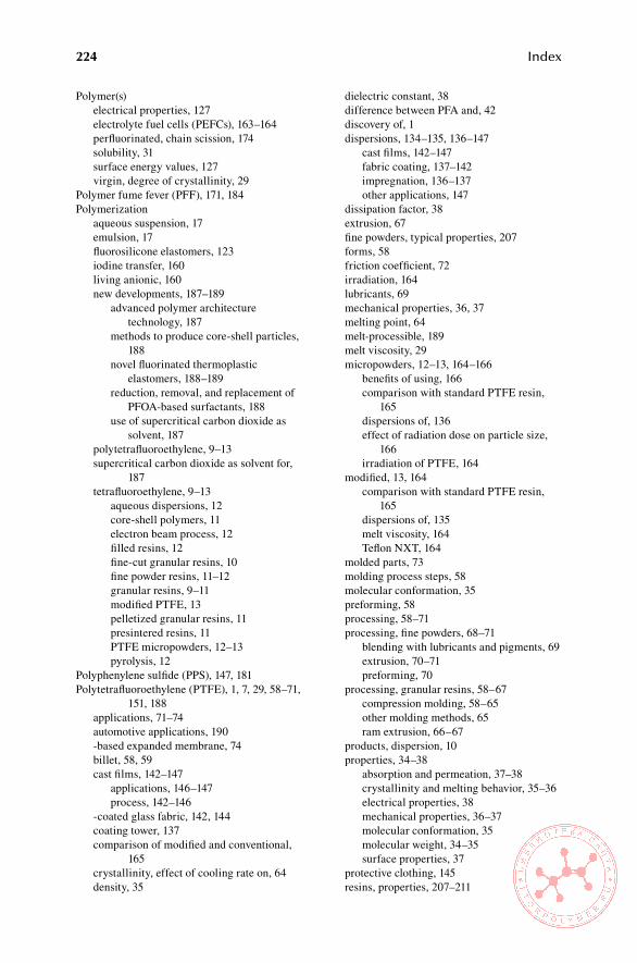
224 Index
Polymer(s) electrical properties, 127 electrolyte fuel cells (PEFCs), 163–164 perfluorinated, chain scission, 174 solubility, 31 surface energy values, 127 virgin, degree of crystallinity, 29Polymer fume fever (PFF), 171, 184Polymerization aqueous suspension, 17 emulsion, 17 fluorosilicone elastomers, 123 iodine transfer, 160 living anionic, 160 new developments, 187–189 advanced polymer architecture
technology, 187 methods to produce core-shell particles,
188 novel fluorinated thermoplastic
elastomers, 188–189 reduction, removal, and replacement of
PFOA-based surfactants, 188 use of supercritical carbon dioxide as
solvent, 187 polytetrafluoroethylene, 9–13 supercritical carbon dioxide as solvent for,
187 tetrafluoroethylene, 9–13 aqueous dispersions, 12 core-shell polymers, 11 electron beam process, 12 filled resins, 12 fine-cut granular resins, 10 fine powder resins, 11–12 granular resins, 9–11 modified PTFE, 13 pelletized granular resins, 11 presintered resins, 11 PTFE micropowders, 12–13 pyrolysis, 12Polyphenylene sulfide (PPS), 147, 181Polytetrafluoroethylene (PTFE), 1, 7, 29, 58–71,
151, 188 applications, 71–74 automotive applications, 190 -based expanded membrane, 74 billet, 58, 59 cast films, 142–147 applications, 146–147 process, 142–146 -coated glass fabric, 142, 144 coating tower, 137 comparison of modified and conventional,
165 crystallinity, effect of cooling rate on, 64 density, 35
dielectric constant, 38 difference between PFA and, 42 discovery of, 1 dispersions, 134–135, 136–147 cast films, 142–147 fabric coating, 137–142 impregnation, 136–137 other applications, 147 dissipation factor, 38 extrusion, 67 fine powders, typical properties, 207 forms, 58 friction coefficient, 72 irradiation, 164 lubricants, 69 mechanical properties, 36, 37 melting point, 64 melt-processible, 189 melt viscosity, 29 micropowders, 12–13, 164–166 benefits of using, 166 comparison with standard PTFE resin,
165 dispersions of, 136 effect of radiation dose on particle size,
166 irradiation of PTFE, 164 modified, 13, 164 comparison with standard PTFE resin,
165 dispersions of, 135 melt viscosity, 164 Teflon NXT, 164 molded parts, 73 molding process steps, 58 molecular conformation, 35 preforming, 58 processing, 58–71 processing, fine powders, 68–71 blending with lubricants and pigments, 69 extrusion, 70–71 preforming, 70 processing, granular resins, 58–67 compression molding, 58–65 other molding methods, 65 ram extrusion, 66–67 products, dispersion, 10 properties, 34–38 absorption and permeation, 37–38 crystallinity and melting behavior, 35–36 electrical properties, 38 mechanical properties, 36–37 molecular conformation, 35 molecular weight, 34–35 surface properties, 37 protective clothing, 145 resins, properties, 207–211
Index 225
aqueous dispersions, 211 fine powders, 207 granular resins, 208 micropowders, 209–210 resins, reprocessed, 181 roofing elements, 144 scrap degradation of, 12 processing, 181 stadium roof, 143 surface properties, 37 thermal degradation, 172 transitions, 36 use in fluid-conveying systems, 72 vacuum thermal degradation of, 171 volume resistivity, 38Polyurethanes, fluorinated, 156–160 cladding for optical fibers, 159 elastomers, 159 medical and dental applications, 159 other applications, 160 powder coatings, 159 protective coating, 158 surface coatings, 156–159 treatments of textile, leather, and other
substrates, 159 water-based coatings, 159Polyvinyl fluoride (PVF), 1, 18, 50–53 chemical properties, 50 decomposition, 172 electrical properties, 52 general properties, 50 industrial process, 18 industrial synthesis, 18 optical properties, 52 processing and applications, 87–88 applications, 88 processing, 87 properties of measured on films, 52 structurally modified, 87 thermal stability, 52–53 weathering performance, 52Polyvinylidene fluoride (PVDF), 16, 44–47, 188 alternating units, 31 catalytic pyrolysis, 16 chemical properties, 47 commercial products based on, 17 dispersions, 148 applications, 148 processing, 148 electrical properties, 45, 47 emulsion polymerization, 17 flexural modulus, 33 industrial process, 17 industrial synthesis, 16 insulation, 82 mechanical properties, 45
properties, 17 typical properties, 46PPS, see Polyphenylene sulfidePPVE, see Perfluoropropylvinyl etherProcessing and applications of commercial
fluoroplastics, 57–91 annealing, 62 automatic molding, 65 billet, 58, 59 coining, 65 degassing, 61 dwell time, 60 freezing range, 62 hourglassing, sintered billet, 60 isostatic molding, 65 melt-processible fluoroplastics, applications,
78–87 ECTFE, 83–86 ethylene and tetrafluoroethylene
copolymers, 79–81 FEP, 78 HTE fluorothermoplastics, 87 PFA and MFA, 78 polychlorotrifluoroethylene, 82–83 PVDF, 81–82 THV fluorothermoplastics, 86–87 melt-processible fluoroplastics, processing,
74–75, 75–78 ethylene and chlorotrifluoroethylene,
copolymers 77 ethylene and tetrafluoroethylene
copolymers, 75–76 polychlorotrifluoroethylene, 77 polyvinylidene fluoride, 76–77 THV fluoroplastics, 77–78 mold filling, 60 polytetrafluoroethylene, processing, 58–71 fine powders, 68–71 granular resins, 58–67 polyvinylfluoride, processing and
applications, 87–88 applications, 88 processing, 87 preforming, 58 pressure sintering and cooling, 63 PTFE applications, 71–74 ram extrusion, 66 resting time, 61 skiving, 65Properties of commercial fluoropolymers, 29–56 Achilles’ heels of, 30 carbon bond energies, 30 chemical resistance, 30 dissipation factor, 38 Dyneon fluoroplastics, 51 elongation values, 32 flexural modulus values, 33

226 Index
individual commercial fluoropolymers, 34–53 ethylene and chlorotrifluoroethylene
copolymer, 48 ethylene and tetrafluoroethylene
copolymer, 43 hexafluoropropylene, tetrafluoroethylene,
and ethylene terpolymer, 49 polychlorotrifluoroethylene, 47–48 polytetrafluoroethylene, 34–38 polyvinyl fluoride, 50–53 polyvinylidene fluoride, 44–47 tetrafluoroethylene and
hexafluoropropylene copolymer, 38–40
tetrafluoroethylene, hexafluoropropylene, and vinylidene fluoride terpolymer, 48–49
tetrafluoroethylene and perfluoroalkyl ethers copolymer, 41–42
maximum service temperatures, 32 as related to polymer structure, 29–34 fluoroelastomers, 33–34 fluoroplastics, 29–33 TEDLAR films, 53 Teflon AF, 33 virgin polymer degree of crystallinity, 29 volume resistivity, 38PTFE, see PolytetrafluoroethylenePVDF, see Polyvinylidene fluoridePVF, see Polyvinyl fluoride
RRadiation, see Heat, radiation, and environment
effects on fluoropolymers; Ionizing radiation
Ram extrusion, 66Recycling of fluoropolymers, 181Reduction–activation systems, 9Refrigerants, 1Resin(s) granular, 9 polytetrafluoroethylene, 58–67, 208 tetrafluoroethylene, 9–11 perfluoroalkoxy, 14–15 industrial process, 15 industrial synthesis, 14 properties, 15 polytetrafluoroethylene, 207–211 aqueous dispersions, 211 fine powders, 207 granular resins, 208 micropowders, 209–210 reprocessed, 181 tetrafluoroethylene, 9–13 filled resins, 12 fine-cut granular resins, 10 fine powder resins, 11–12
granular resins, 9–11 pelletized granular resins, 11 presintered resins, 11
sSafety, hygiene, and disposal of fluoropolymers,
183–186 exposure to decomposition products, 184 exposure limit types, 185 fluoroelastomers, 186 disposal of production and post-consumer
scrap, 186 processing safety and hygiene, 186 use safety and hygiene, 186 fluoroplastics, 183–185 environmental protection and disposal
methods, 185 food contact, 185 medical applications, 185 thermal behavior, 183–184 toxicology, 183 Food, Drug and Cosmetic Act, 185 hazardous fluids, 186 maximum continuous-use and processing
temperatures, 184 polymer fume fever, 184Silverstone, 147Skiving, 65Society of Plastics Industry, Inc. website, 194SSG, see Standard specific gravityStandard specific gravity (SSG), 35
TTeflon AF, 33, 151, 152, 176Teflon-coated cookware, 193Teflon NXT, 164Telecommunications, new developments, 191Tetrafluoroethylene (TFE), 30, 74, 187 amorphous fluoropolymers based on, 151 aqueous dispersion, 9 dispersion homopolymerization, 14 equipment used in handling, 8 first synthesis of, 7 fluorocarbon elastomers based on, 93 industrial synthesis, 7–8 manufacturing steps, 7–8 polymerization, 9–13 aqueous dispersions, 12 core-shell polymers, 11 dispersion, 11 electron beam process, 12 filled resins, 12 fine-cut granular resins, 10 fine powder resins, 11–12 granular resins, 9–11 modified PTFE, 13
Index 227
pelletized granular resins, 11 PTFE micropowders, 12–13 pyrolysis, 12 properties of, 8–9 thermal stability, 173 uses of, 9Tetrafluoroethylene and hexafluoropropylene,
copolymers of, 38–40 chemical properties, 39–40 electrical properties, 39 mechanical properties, 39 optical properties, 40 other properties, 40 physical and mechanical properties, 41–42Tetrafluoroethylene, hexafluoropropylene, and
vinylidene fluoride, terpolymer of (THV fluoroplastic), 19, 48–49, 77
blow molding, 78 commercial grades of, 19 dispersions, 148–149 applications, 148–149 processing, 148 processing temperatures, 77 refractive index, 86 solvent-based coatings, 189Textile finishes, acrylates, 154–155TFE, see TetrafluoroethyleneThermoplastic elastomers, fluorinated,
applications, 160–162 Cefral Soft, 160 chemical and semiconductor industries, 161 electrical and wire and cable, 161
iodine transfer polymerization, 160 living anionic polymerization, 160 other applications, 162THV fluoroplastic, see Tetrafluoroethylene,
hexafluoropropylene, and vinylidene fluoride, terpolymer of
Trade names, 195–196Transfer molding, 110Trends, see New developments and current trends
UU.S. Environmental Protection Agency (EPA),
193U.S. Food and Drug Administration (FDA), 103,
120, 185U.S. patents, recent, 217–218UV radiation, effects of on fluoropolymers,
176–177
vVDF, see Vinylidene fluorideVibration damping, 39Vinylidene fluoride (VDF), 16, 33, 151Volume resistivity, 38
xXPS, see X-ray photoelectron spectroscopyX-ray photoelectron spectroscopy (XPS), 177