Technician guide alt starter
52
Technicians Guide North American 12-Volt Systems © 2012 Mitsubishi Electric Automotive America, Inc.
-
Upload
ashfaq-hussain -
Category
Engineering
-
view
416 -
download
4
Transcript of Technician guide alt starter

Technicians GuideNorth American 12-Volt Systems
©2012 Mitsubishi Electric Automotive America, Inc.
i
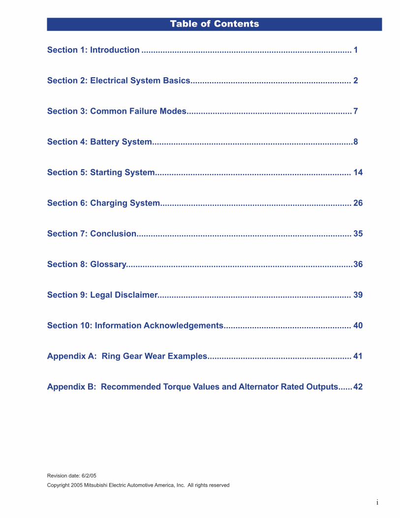
Table of Contents
Section 1: Introduction ......................................................................................... 1
Section 2: Electrical System Basics.................................................................... 2
Section 3: Common Failure Modes...................................................................... 7
Section 4: Battery System..................................................................................... 8
Section 5: Starting System................................................................................... 14
Section 6: Charging System................................................................................. 26
Section 7: Conclusion........................................................................................... 35
Section 8: Glossary................................................................................................ 36
Section 9: Legal Disclaimer.................................................................................. 39
Section 10: Information Acknowledgements...................................................... 40
Appendix A: Ring Gear Wear Examples............................................................. 41
Appendix B: Recommended Torque Values and Alternator Rated Outputs...... 42
Revision date: 6/2/05
Copyright 2005 Mitsubishi Electric Automotive America, Inc. All rights reserved
1
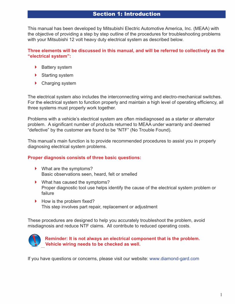
Section 1: Introduction
This manual has been developed by Mitsubishi Electric Automotive America, Inc. (MEAA) with the objective of providing a step by step outline of the procedures for troubleshooting problems with your Mitsubishi 12 volt heavy duty electrical system as described below.
Three elements will be discussed in this manual, and will be referred to collectively as the “electrical system”:
Battery system
Starting system
Charging system
The electrical system also includes the interconnecting wiring and electro-mechanical switches. For the electrical system to function properly and maintain a high level of operating effi ciency, all three systems must properly work together.
Problems with a vehicle’s electrical system are often misdiagnosed as a starter or alternator problem. A signifi cant number of products returned to MEAA under warranty and deemed “defective” by the customer are found to be “NTF” (No Trouble Found).
This manual’s main function is to provide recommended procedures to assist you in properly diagnosing electrical system problems.
Proper diagnosis consists of three basic questions:
What are the symptoms? Basic observations seen, heard, felt or smelled
What has caused the symptoms? Proper diagnostic tool use helps identify the cause of the electrical system problem or failure
How is the problem fi xed? This step involves part repair, replacement or adjustment
These procedures are designed to help you accurately troubleshoot the problem, avoid misdiagnosis and reduce NTF claims. All contribute to reduced operating costs.
Reminder: It is not always an electrical component that is the problem. Vehicle wiring needs to be checked as well.
If you have questions or concerns, please visit our website: www.diamond-gard.com

2
Section 2: Electrical System Basics
2.1 Electrical Fundamentals
Open and Closed CircuitsA closed circuit provides a continuous path for current fl ow. This circuit contains a power source, wires and a load. When referring to a power source it can be either an alternator or the batteries. When referring to the load this can be lights, starter motor or any other device that consumes power.
Figure 1: Open and Closed Circuits
An open circuit contains a disruption in current fl ow. This disruption is usually an air gap or an insulating material. Current is unable to fl ow in an open circuit condition.
Parallel and Series CircuitsIn a series circuit current fl ows through a single path. A fl ashlight is an example of a series circuit. The current fl ows from the battery through a light bulb. If the bulb burns out, the path is disrupted and the circuit is open.
Figure 2: Series and Parallel Circuits
Current fl ows through multiple paths in a parallel circuit. Truck headlights are an example of a parallel circuit. Current fl ows independently to each headlamp from a power source. If one headlight burns out, the other still works. VoltageVoltage is the difference in electrical “pressure” between two points. For example, a properly charged battery has voltage across its positive and negative terminals of approximately 12 volts when it isn’t supplying current.
CurrentCurrent is the fl ow of electrons through a circuit. Two conditions must be met for current fl ow to exist: a closed circuit and voltage. Voltage provides the “pressure” to move the electrons (current) through the circuit.

3
ResistanceResistance is the opposition to current fl ow. Think of resistance as a restriction in a hose’s diameter.
Relationship Between Voltage, Current and AmperageVoltage, Current and Amperage are interrelated. This relationship is expressed through Ohm’s Law: V=I x R. In this equation V=voltage, I=current fl ow and R=resistance.
If two of the values are known, the equation can be manipulated to fi nd the third value. An example is shown below.
Consider the circuit in Figure 3 with resistance A = .01Ω
Connect a voltmeter to the leads of the load
Voltage across the load is 1.0 volt
What is the current fl ow in the circuit with resistance A?
What is the current fl ow in the circuit with resistance B?
LoadR 0.01Ω
V 1.0 volt
V I R
I ?
VR
1.0V0.01Ω1.0V
0.05Ω
Resistance A=0.01Ω
Resistance B .05Ω
Figure 3: Ohm’s Law Example
This discussion’s important point is: Increased resistance leads to reduced current fl ow. During electrical system troubleshooting, increased resistance is shown an increased voltage drop in a circuit.
What is Voltage Drop and why is it important?Voltage drop is the voltage measured between two points in a closed circuit that contains a resistance. Each wire in the vehicle’s charging and starting system has a resistance. This resistance is very low, but is still there. Voltage drop only occurs when current is fl owing through the wire being checked.
Too much resistance in the alternator and starter cables prevents these components from functioning properly. As resistance increases, voltage drop increases. MEAA has calculated the maximum recommended voltage drops for proper function of its products. These values are provided in the troubleshooting sections of this manual.
�
�
�
�
�
4
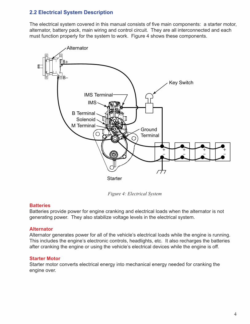
2.2 Electrical System Description
The electrical system covered in this manual consists of fi ve main components: a starter motor, alternator, battery pack, main wiring and control circuit. They are all interconnected and each must function properly for the system to work. Figure 4 shows these components.
Starter
B TerminalSolenoid
IMS TerminalIMS
GroundTerminal
M Terminal
Alternator
Key Switch
Figure 4: Electrical System
BatteriesBatteries provide power for engine cranking and electrical loads when the alternator is not generating power. They also stabilize voltage levels in the electrical system.
Alternator Alternator generates power for all of the vehicle’s electrical loads while the engine is running. This includes the engine’s electronic controls, headlights, etc. It also recharges the batteries after cranking the engine or using the vehicle’s electrical devices while the engine is off.
Starter MotorStarter motor converts electrical energy into mechanical energy needed for cranking the engine over.

5
Main WiringThere are two wiring subsystems related to the charging and cranking circuits:
First subsystem
Supplies power from batteries to starter motor
Wires are most noticeable
Large enough to transmit several hundred amperes during cranking
Transmit power back to batteries from alternator for charging
Second subsystem
Transmits power from the alternator to the batteries for charging
Usually connected from the alternator to the starter
Control CircuitControl circuit transmits power to starter’s solenoid
Includes key switch and associated wiring
Starter motor receives “start” signal from control circuit
Section 5.5, Step 4 provides an explanation of possible control circuit confi gurations
Figure 4 illustrates typical control circuit confi guration
�
�
�
�
�
�
�
�
�
�
�
�
6
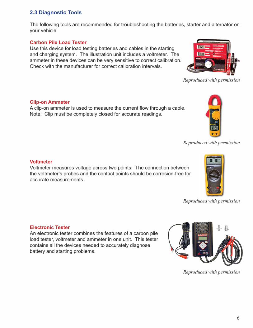
2.3 Diagnostic Tools
The following tools are recommended for troubleshooting the batteries, starter and alternator on your vehicle:
Carbon Pile Load TesterUse this device for load testing batteries and cables in the starting and charging system. The illustration unit includes a voltmeter. The ammeter in these devices can be very sensitive to correct calibration. Check with the manufacturer for correct calibration intervals.
Clip-on AmmeterA clip-on ammeter is used to measure the current fl ow through a cable. Note: Clip must be completely closed for accurate readings.
VoltmeterVoltmeter measures voltage across two points. The connection between the voltmeter’s probes and the contact points should be corrosion-free for accurate measurements.
Electronic TesterAn electronic tester combines the features of a carbon pile load tester, voltmeter and ammeter in one unit. This tester contains all the devices needed to accurately diagnose battery and starting problems.
Reproduced with permission
Reproduced with permission
Reproduced with permission
Reproduced with permission

7
Section 3: Common Failure Modes
Below is a guide for determining the proper troubleshooting steps for some common failures. See Sections 4, 5 and 6 for detailed troubleshooting steps. Troubleshooting fl owcharts are available at the end of each section.
Section 4: Batteries
Section 5: Starting
Cranking OK?
Yes
Section 6: Charging
Section 5: Starting
Appendix A: Ring Gear Wear Examples
Section 4: Batteries
Section 6: Charging
Slow CrankingNo CrankingDim Lights
“Click no crank”
Dry BatteriesLeaking BatteriesBright/Burned Out
Bulbs
Finished
Finished
Finished
Finished
Finished
No
Cranking OK?
No
Cranking OK? No
YesSection 6: Charging
Yes
Finished
Section 4: Batteries

8
Section 4: Battery Systems
Section 4.1: Battery Safety
NOTE: This section is for informational purposes only. Refer to your battery manufacturer for proper safety and testing procedures.
Refer to the vehicle and battery manufacturers’ safety procedures before any handling, charging or storage of the vehicle’s batteries.
Section 4.2: State of Charge
State of charge is a measure of the amount of usable power remaining in a battery. General rule: A battery needs a minimum of 75% state of charge for proper cranking.
Three methods are available for checking the state of charge in a battery: specifi c gravity, open circuit voltage and electronic battery testers.
Specifi c gravity test is a measure of a battery’s electrolyte density compared to the density of water. A hydrometer is used to measure a battery’s specifi c gravity. Some batteries have a built in hydrometer.
Batteries without a built-in hydrometer
Test can only be performed on batteries with removable vent caps
Refer to the battery manufacturer’s specifi cations for hydrometer values
Batteries with a built-in hydrometer
Refer to the vehicle or battery manufacturers’ instructions for reading the built-in hydrometer
Open circuit voltage (OCV) test is a voltage measurement across a battery’s terminals under a no-load condition.
Use test to determine state of charge for batteries without removable vent caps
OCV’s negative aspect is the possibility of inaccurate voltage readings due to battery surface charge
Surface charge is an effect of charging lead-acid batteries
Can lead to inaccurate OCV tests
Refer to battery manufacturer’s recommendations for identifying and removing surface charge
Refer to battery manufacturer’s specifi cations for state of charge percentages based on OCV values
Electronic battery testers display state of charge based on an internal algorithm
Refer to battery manufacturer’s recommendations for use of electronic testers
�
�
�
�
�
�
�
�
�
�
�
�
9
4.3 Battery Charging Basics
This section will help determine the time required to charge a vehicle’s batteries, and is meant for informational purposes only. Refer to the battery manufacturer for proper charging procedures.
Batteries used in vehicle starting systems generally come with a reserve capacity rating.
Good for comparing battery capacities
Doesn’t help determine charging times
Need to know battery’s ampere-hour capacity
A battery’s ampere-hour capacity is a measure of the electrical energy a battery can supply at a defi ned temperature, amperage and cut-off voltage.
Multiply reserve capacity in minutes by 0.6 to determine approximate 20-hour ampere-hour capacity
Example: A 100 ampere-hour battery will supply 5 amperes for 20 hours
12 volt battery at 80° F, discharged to 10.5 volts
Equation 1: Ampere-hours=amps x hours
State of charge is a measure of the number of ampere-hours remaining in the battery pack. Example: If 50 ampere-hours are used from a 100 ampere-hour battery pack, 50 ampere-hours remain and the battery pack is at a 50% state of charge.
Equation 2: % charge = ampere-hours remaining ÷ ampere-hours at full charge
Equation 3: Ampere-hours remaining = % charge × ampere-hours at full charge
Equation 4: Ampere-hours used = Ampere-hours at full charge – Ampere-hours remaining
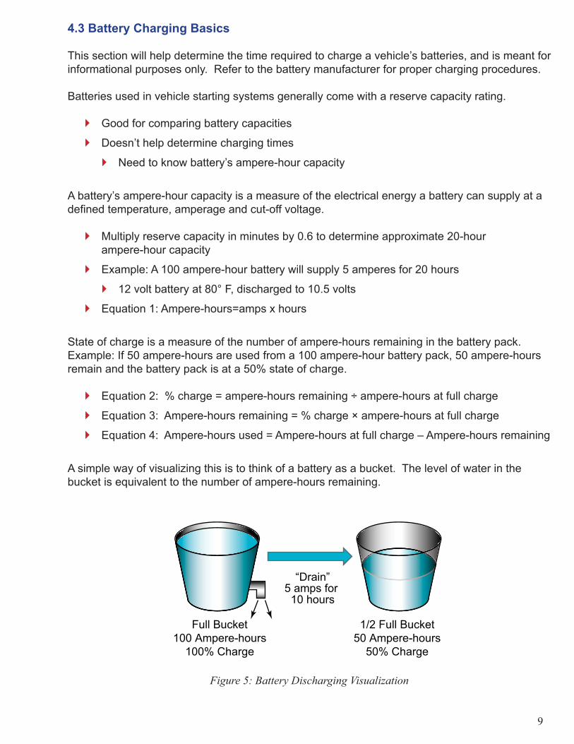
A simple way of visualizing this is to think of a battery as a bucket. The level of water in the bucket is equivalent to the number of ampere-hours remaining.
Full Bucket100 Ampere-hours
100% Charge
1/2 Full Bucket50 Ampere-hours
50% Charge
“Drain”5 amps for 10 hours
Figure 5: Battery Discharging Visualization
�
�
�
�
�
�
�
�
�
�

10
This information is important because it determines the length of time necessary to charge a battery to an acceptable level for testing. The principles for “draining” the battery hold true for charging the battery. If you remove 50 ampere-hours from the battery as in Figure 5, it must be placed back to return the battery to 100% charge.
Battery chargers are rated by the number of amps they can supply for charging. This rate is the “amps” listed in Equation 1.
1/2 Full Bucket50 Ampere-hours
50% Charge
“Fill”5 amps for 10 hours
Full Bucket100 Ampere-hours
100% Charge
Figure 6: Battery Charging Visualization
As you can see from Figure 6, you need to put 50 ampere-hours back into the bucket to fi ll it upWould take at least 10 hours at a rate of 5 amps
Above situation is ideal: Times will increase slightly due to charging losses
Add the capacity of each battery together to determine the number of ampere-hours in a battery pack connected in parallel.
=400 Ampere-hours
=100 Ampere-
hours
=100 Ampere-
hours
=100 Ampere-
hours
=100 Ampere-
hours
Figure 7: Batteries in Parallel
If the batteries shown in Figure 7 were all at 50% charge and were charged with a 50 amp charger, it would take at least 4 hours to charge the batteries.
Consider two options for the above situation
Charge the batteries while still in the vehicle
Leads to downtime
Charge to at least 75% state of charge
Charge the batteries after removal from vehicle
Spare battery pack needed
�
�
�
�
�
�
�
11
4.4 Proper Battery Maintenance
Make sure the battery manufacturer’s recommended diagnostic tools are available before beginning diagnosis. Equipment commonly recommended for battery testing include carbon pile load testers or computerized test devices.
Properly charged and tested batteries are required for the proper diagnosis of the starting and charging systems.
Discharged batteries indicate the possibility of problems with the starting or charging system or parasitic loads
The fi rst step in any charging or starting system diagnosis procedure is to determine whether the vehicle’s batteries are at fault. Eliminating the batteries as a source of problems reduces the number of potential sources of failure
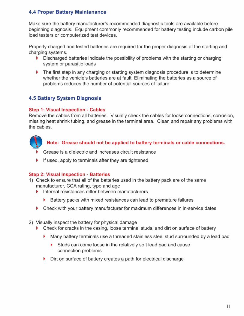
4.5 Battery System Diagnosis
Step 1: Visual Inspection - CablesRemove the cables from all batteries. Visually check the cables for loose connections, corrosion, missing heat shrink tubing, and grease in the terminal area. Clean and repair any problems with the cables.
Note: Grease should not be applied to battery terminals or cable connections.
Grease is a dielectric and increases circuit resistance
If used, apply to terminals after they are tightened
Step 2: Visual Inspection - Batteries1) Check to ensure that all of the batteries used in the battery pack are of the same manufacturer, CCA rating, type and age
Internal resistances differ between manufacturers
Battery packs with mixed resistances can lead to premature failures
Check with your battery manufacturer for maximum differences in in-service dates
2) Visually inspect the battery for physical damageCheck for cracks in the casing, loose terminal studs, and dirt on surface of battery
Many battery terminals use a threaded stainless steel stud surrounded by a lead pad
Studs can come loose in the relatively soft lead pad and cause connection problems
Dirt on surface of battery creates a path for electrical discharge
�
�
�
�
�
�
�
�
�
�
�

12
Step 3: State of Charge & TestingAfter performing the visual inspection, determine the state of charge as discussed in Section 4.2 and test per the battery manufacturer’s recommendations for each battery in the pack.
Testing determines the battery’s ability to supply cranking current
Check with battery manufacturer for replacement guidelines if any batteries in the pack fail
Step 4: Retighten CablesThe completion of the above steps ensures that good batteries are installed in the vehicle and removes one variable from the troubleshooting process. It is now time to proceed to the charging or cranking portion of the manual, depending on the particular problem.
�
�
13
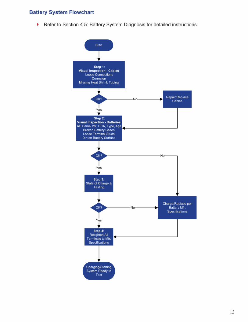
Battery System Flowchart
Refer to Section 4.5: Battery System Diagnosis for detailed instructions�
Step 1:Visual Inspection - Cables
Loose ConnectionsCorrosion
Missing Heat Shrink Tubing
Step 2:Visual Inspection - BatteriesAll: Same Mfr, CCA, Type, Age
Broken Battery CasesLoose Terminal StudsDirt on Battery Surface
Step 3:State of Charge &
Testing
Charge/Replace perBattery Mfr.
SpecificationsOK?
Step 4:Retighten All
Terminals to Mfr.Specifications
Yes
OK? Repair/ReplaceCables
Yes
Charging/StartingSystem Ready to
Test
Start
No
OK? No
Yes
No

14
Section 5: Starting System
5.1 Safety Be sure to follow proper safety techniques as outlined by your shop or employer.
This includes wearing safety glasses and gloves at all times, and disconnecting the vehicle’s batteries during any repair of the starting system. Make sure the vehicle is out of gear, parking brake is set and the wheels are chocked. Also avoid wearing jewelry or loose fi tting clothing.
The components tested in this section may continue to have power supplied to them even when the ignition switch is off. Use extreme caution at all times.
Caution: Do not attempt to start the engine by connecting the starter’s B terminal to the M terminal. Extremely high levels of current can fl ow through the device you are using to connect the terminals and is extremely dangerous.
5.2 Tool RequirementsThree basic tools are needed for starting system diagnosis:
Ammeter
Multimeter capable of measuring voltage
Carbon pile load tester (load tester)
An electronic tester can be used in place of the above tools.
5.3 Overview of the Mitsubishi Electric Class 8 Planetary Gear Reduction Starter – Model 105P55105P55 =105 - 105mm yoke outside diameterP - Planetary Gear design55 - 5.5 kW output
Mitsubishi Electric pioneered the introduction of the planetary gear reduction starter in 1983 and MEAA introduced it in North America for heavy duty truck applications in 1998. This planetary gear reduction technology was a signifi cant improvement over previous direct drive and offset gear reduction technology by providing a smaller, lighter, higher output, and more durable design. Such high output in a small package is achieved by the use of gear reduction technology that allows the armature to rotate at a much higher RPM, creating higher torque at the output shaft and at the starter pinion.
�
�
�
15
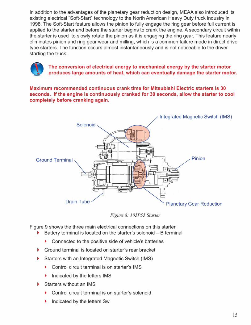
In addition to the advantages of the planetary gear reduction design, MEAA also introduced its existing electrical “Soft-Start” technology to the North American Heavy Duty truck industry in 1998. The Soft-Start feature allows the pinion to fully engage the ring gear before full current is applied to the starter and before the starter begins to crank the engine. A secondary circuit within the starter is used to slowly rotate the pinion as it is engaging the ring gear. This feature nearly eliminates pinion and ring gear wear and milling, which is a common failure mode in direct drive type starters. The function occurs almost instantaneously and is not noticeable to the driver starting the truck.
The conversion of electrical energy to mechanical energy by the starter motor produces large amounts of heat, which can eventually damage the starter motor.
Maximum recommended continuous crank time for Mitsubishi Electric starters is 30 seconds. If the engine is continuously cranked for 30 seconds, allow the starter to cool completely before cranking again.
Planetary Gear Reduction
Pinion
Integrated Magnetic Switch (IMS)
Ground Terminal
Drain Tube
Solenoid
Figure 8: 105P55 Starter
Figure 9 shows the three main electrical connections on this starter.Battery terminal is located on the starter’s solenoid – B terminal
Connected to the positive side of vehicle’s batteries
Ground terminal is located on starter’s rear bracket
Starters with an Integrated Magnetic Switch (IMS)
Control circuit terminal is on starter’s IMS
Indicated by the letters IMS
Starters without an IMS
Control circuit terminal is on starter’s solenoid
Indicated by the letters Sw
�
�
�
�
�
�
�
�
�

16
Integrated Magnetic Switch
Starter without IMSStarter with IMS
IMS Terminal
Sw TerminalB Terminal
M Terminal
B Terminal
Ground Terminal
Ground Terminal
Figure 9: Starter Terminal Locations
5.4 Important Considerations before TroubleshootingStarting an engine requires more current draw than any other electrical operation. For this reason battery condition and electrical connections are very important.
Charge the batteries to a minimum 75% state of charge before testing the starting system
Otherwise test results will be inaccurate
Maintaining proper state of charge ensures batteries have needed energy to crank engine
Low state of charge increases time starter must work
Leads to earlier failure
Newer engine control systems may not supply fuel to the engine’s cylinders if cranking speed is below a certain RPM
Complete the voltage drop tests in Section 5.5, Step 3
Ensures cables can transmit required current
High voltage drops may result in longer cranking times
Connecting a voltmeter to the starter to determine if voltage is present is not a suffi cient substitute for Step 3.
�
�
�
�
�
�
�
�
�

17
5.5 Starting System DiagnosisStep 1: Battery CheckCheck vehicle’s batteries as outlined in Section 4. Properly charged batteries are needed to perform the voltage drop tests detailed later in this section. Confi rmed properly charged batteries also remove a variable in the diagnosis of the starting system and ultimately save time.
Step 2: Visual CheckInspect all cables and connections in the starting system for corrosion, loose connections and frayed cables.
Cable insulation bulge is an indicator of corrosion inside cable
Use a wire brush to clean all corroded connections to bare metal and retighten
Check all connections for proper torque
Starter torque specifi cations can be found in Appendix B
Check with the vehicle manufacturer for battery torque specifi cations. Proper operation of the starting system depends on good connections between electrical components
Visually checking cables is not a substitute for load testing the cables as provided in Section 5.5, Step 3. Load testing can reveal problems that a visual check can miss.
Step 3: Starter Circuit TroubleshootingThe following are instructions for using a carbon pile load tester and voltmeter. Consult the tester’s manual if using an electronic load tester that combines the features of a load tester and voltmeter.
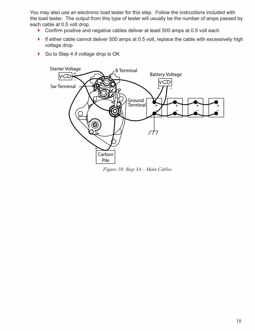
Step 3A: Main CablesBegin by testing current carrying capability of main cables1) As shown in Figure 10, connect a carbon pile load tester to B and ground terminals of the starter
Maintain a load of 500 amps while performing the step below
2) Using the wiring confi guration in Figure 10, obtain:Starter Voltage
Battery Voltage
3) Use the formula shown below to calculate the voltage dropGo to Step 3B if voltage drop exceeds 1.0 volt
Indicates problem with cables
Go to Step 4 if voltage drop is below 1.0 volt
Main cables are OK
Voltage Drop = Battery voltage - Starter Voltage
�
�
�
�
�
�
�
�
�
�
�
�
18
You may also use an electronic load tester for this step. Follow the instructions included with the load tester. The output from this type of tester will usually be the number of amps passed by each cable at 0.5 volt drop.
Confi rm positive and negative cables deliver at least 500 amps at 0.5 volt each
If either cable cannot deliver 500 amps at 0.5 volt, replace the cable with excessively high voltage drop
Go to Step 4 if voltage drop is OK
Figure 10: Step 3A – Main Cables
�
�
�
19
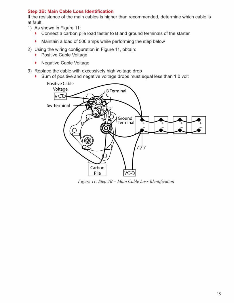
Step 3B: Main Cable Loss Identifi cationIf the resistance of the main cables is higher than recommended, determine which cable is at fault. 1) As shown in Figure 11:
Connect a carbon pile load tester to B and ground terminals of the starter
Maintain a load of 500 amps while performing the step below
2) Using the wiring confi guration in Figure 11, obtain:Positive Cable Voltage
Negative Cable Voltage
3) Replace the cable with excessively high voltage drop Sum of positive and negative voltage drops must equal less than 1.0 volt
Figure 11: Step 3B – Main Cable Loss Identifi cation
�
�
�
�
�

20
Step 4: Control CircuitThis step tests the vehicle’s ability to send a “start” signal to the starter. Continue to step 4A if your starter is equipped with an Integrated Magnetic Switch. Continue to step 4B if your starter does not have an Integrated Magnetic Switch.
Integrated Magnetic Switch
Starter without IMSStarter with IMS
IMS Terminal
M Terminal
Sw TerminalB Terminal
B Terminal
Ground Terminal
Ground Terminal
Figure 12: Starter Type Identifi cation
Step 4A: Starter with Integrated Magnetic Switch1) Disconnect wire from IMS terminal on the Integrated Magnetic Switch
See Figure 13 or 14 for key switch circuit diagram, depending on vehicle’s electrical system
2) Connect a test light between ground and disconnected cable in above step3) Turn the key switch to the “start” position
Continue to Step 5 if test light operates
Troubleshoot key switch, key switch wiring if light does not operate
Some vehicles require the clutch to be disengaged or the vehicle to be in park for control circuit operation
Perform at least 3 times
Some remote mounted relays contain a disc with more than one contact point
Step 4A is the only test in this manual where a test light is used.
�
�
�
�
�
�

21
B Terminal
IMSTerminal
Disconnect
Ground
Test LightRemotelyMounted
Relay
T
Figure 13: Step 4A – Key Switch Circuit w/ Remote Mounted Relay
Disconnect
Test Light
T
B Terminal
IMSTerminal
Ground
Figure 14: Step 4A – Key Switch Circuit w/o Remote Mounted Relay

22
Step 4B: Starter without Integrated Magnetic Switch1) Remove cable from starter’s Sw terminal only2) Connect carbon pile load tester to starter’s ground terminal and cable removed from starter’s Sw terminal as shown in Figure 15
Maintain 80 amp load while performing step below
Turn key switch on while performing step below
Some vehicles require the clutch to be disengaged or the vehicle to be in park for control circuit operation.
3) Using the wiring confi guration in Figure 15, obtain:B-cable Drop
Sw-cable Drop
Starter Relay Drop
Collect at least 3 times
Some remote mounted relays contain a disc with more than one contact point
4) Use the formula shown below to calculate control circuit voltage dropVoltage drop must not exceed 0.8 volt
If the voltage drop exceeds 0.8 volt, replace the cable or starter relay with the excessive voltage drop
Control Circ. Voltage Drop = B-cable Drop + Sw-cable Drop + Starter Relay Drop
B TerminalSw Terminal
Disconnect
KeySwitch
B Cable Drop
SW Cable Drop
Starter Relay Drop
Figure 15: Step 4B – Starter w/o Integrated Magnetic Switch
�
�
�
�
�
�
�
�
�
�
23
A starter relay that appears to work correctly during diagnosis does not mean it will always work correctly in the fi eld.
Factors such as temperature, humidity and vibration can affect a relay’s performance
Replace the remotely mounted starter relay if found defective
Genuine Mitsubishi relays are available from your dealer
Step 5: Retest Starting SystemReconnect all starting circuits and double check for corrosion or loose connections. Attempt to start the vehicle.
Starter motor does not need to be replaced if vehicle starts correctly
Continue to Section 5.6 if vehicle does not start
Replacement IMS and Solenoid kits are available from your dealer
5.6 Starter Motor ReplacementDiagnostic steps for determining if the starter motor is at fault are completed. Result: Replace the starter motor.
Step 1: Starter Removal1) Disconnect vehicle’s batteries2) Remove cables connected to starter’s ground and B terminal
Note cable location for reinstallation
3) Remove the cable connected to the IMS terminal or Sw terminalTerminal depends on starter model
4) Remove three mounting bolts connecting starter to engine
Step 2: Ring Gear Wear Check1) Check the engine’s ring gear for excessive wear before installing a new starter
Due to six cylinder diesel engine design characteristics, the ring gear will always come to rest in one of three possible positions
Check all three ring gear positions for wear
Commonly called “barring over” the engine
See Appendix A for wear examples
Step 3: Starter Motor Reinstallation1) Install new starter by reversing steps used for removal
Protect starter motor’s pinion from impacts during installation
Roughness on pinion surfaces can lead to ring gear engagement errors
See Appendix B for recommended torque values
�
�
�
�
�
�
�
�
�
�
�
�
�
�
�

24
Step 4: Final Visual Check1) Visually inspect starting system’s electrical connections2) There should be no gaps between the starter fl ange and the fl ywheel housing
Improper mounting can lead to:
Damaged pinion and ring gear
Engagement errors
Stuck pinion
Premature starter failure
Congratulations! You have now successfully completed troubleshooting your vehicle’s starting system.
�
�
�
�
�

25
Starting System Diagnosis FlowchartRefer to Section 5.5: Starting System Diagnosis for detailed instructions
Step 1: CheckBatteries
(See BatteryFlowchart)
OK?
Repair/ReplaceBatteries
(See BatteryFlowchart)
Step 3A: Check MainBattery Cables
Step 2: Visual CheckCorrosion
Loose ConnectionsCable BulgesProper Torque
Yes
OK? Repair/ReplaceBad Parts
Yes
VoltageDrop
Step 3B: Main Cable LossIdentification
Repair/Replace main cable w/excessive loss
Step 4: KeySwitch Circuit
Troubleshoot KeySwitch Circuit
≤1.0 volt@ 500 A
Step 5: RetestStarter Operation
Yes
OK?
Yes
Start
End Replace StarterMotor
No
No
>1.0 volt@ 500 A
Doesvehiclestart?
No
EndYes
OK? No
No
*Replacement IMS andsolenoid kits are available
from your dealer
IMS – Integrated MagneticSwitch
�
26
Section 6: Charging System
6.1 Safety Be sure to follow proper safety techniques as outlined by your shop or employer.
This includes wearing safety glasses and gloves at all times, and disconnecting the vehicle’s batteries during any repair of the charging system. Make sure the vehicle is out of gear, parking brake is set and the wheels are chocked. Also, avoid wearing jewelry or loose fi tting clothing.
The components tested in this section may continue to have power supplied to them even when the ignition switch is off. Use extreme caution at all times.
6.2 Tool RequirementsThree basic tools are needed for charging system diagnosis:
Ammeter
Multimeter capable of measuring voltage
Carbon pile load tester (load tester)
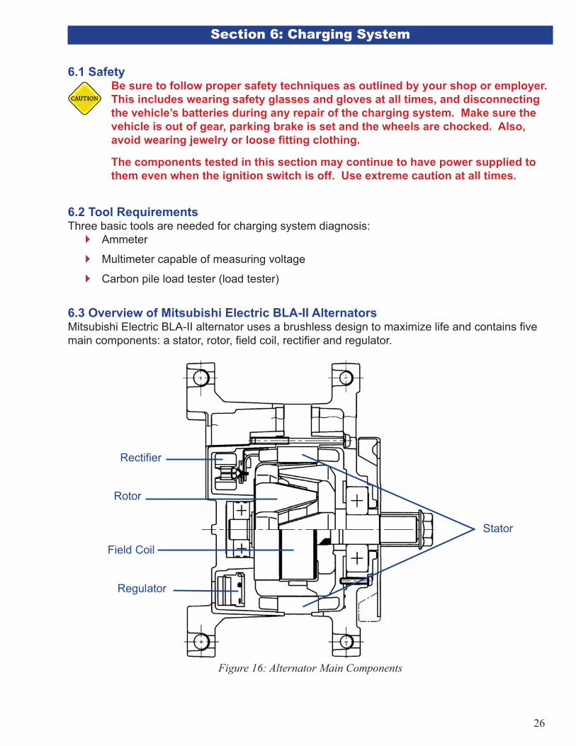
6.3 Overview of Mitsubishi Electric BLA-II AlternatorsMitsubishi Electric BLA-II alternator uses a brushless design to maximize life and contains fi ve main components: a stator, rotor, fi eld coil, rectifi er and regulator.
Regulator
Rotor
Rectifier
Stator
Field Coil
Figure 16: Alternator Main Components
�
�
�

27
RotorRotor is rotated by a shaft connected to the alternator pulley. It is responsible for inducing voltage in the stator. The rotor’s poles create a change in magnetic fl ux in the stator.
StatorStator produces the current supplied by the alternator to the vehicle. The change in magnetic fl ux produced by the spinning rotor induces a voltage in the stator.
Field CoilField coil induces a magnetic fi eld in the rotor. This is accomplished by supplying power to the fi eld coil.
Rectifi erRectifi er converts the 3-phase AC current produced by the stator into the DC current used by a vehicle’s electrical system.
RegulatorRegulator controls the alternator’s output voltage by varying the current supplied to the fi eld coil. Mitsubishi Electric alternators have temperature compensated regulators, which increase output voltage as ambient temperature decreases. This increases the alternator’s ability to charge the batteries during cold weather.
6.4 Charging System DiagnosisStep 1: Battery Check Check the vehicle’s batteries as outlined in Section 4
Charged batteries are needed to perform voltage drop tests detailed later in this section
Removes a variable in charging system diagnosis and ultimately saves time
Step 2: Visual CheckInspect all cables and connections in the charging system for corrosion, loose connections and frayed cables
Proper charging system operation depends on good connections between electrical components
Use a wire brush to clean all corroded connections to bare metal
Retighten connections
Bulges in cable insulation are an indicator of corrosion inside of cables
Check all connections for proper torque
See Appendix B for alternator torque specifi cations
Check with the vehicle manufacturer for other torque specifi cations
Check the alternator’s pulley nut for correct torqueSee Appendix B for torque specifi cations
Use an 8 mm hex wrench and a 24 mm torque wrench for pulley nut tightening
Do not use a screwdriver or other device to hold the cooling fi ns of the alternator when tightening the pulley nut
�
�
�
�
�
�
�
�
�
�
�
�

28
Check the vehicle’s accessory belt for proper tension and damage such as cracking, fraying, glazing, etc. Improper tension or poor belt condition can lead to belt slippage, which can result in reduced alternator output. This ultimately results in improper system diagnosis.
Step 3: Charging Circuit Cable CheckCharging circuit cables transmit power from the alternator to the batteries. These cables need to be capable of transmitting the alternator’s rated output to the batteries with a maximum of 0.5 volt drop between the alternator and batteries.
Ensure the vehicle’s batteries all have a minimum 75% state of charge before continuing. Test results will be inaccurate otherwise.
Step 3A: Main Cable CheckBegin by testing the main cables’ current carrying capability 1) With engine off, connect carbon pile load tester to alternator’s B+ and B- terminals as shown in Figure 172) Increase load on load tester to alternator’s rated amperage while performing the step below
Rated amperages for each alternator model can be found in Appendix B
3) Using the wiring confi guration in Figure 17, obtain:Battery Voltage
Alternator Voltage
4) Use the formula shown below to calculate the voltage dropGo to Step 3B if voltage drop exceeds 0.5 volt
Indicates problem with cables
Go to Step 4 if voltage drop is below 0.5 volt
Main cables are OK
Voltage drop = battery voltage – alternator voltage
Alternator
Figure 17: Step 3A – Main Cable Check
�
�
�
�
�
�
�

29
Step 3B: Individual Cable CheckThis check identifi es whether the positive or negative cable from the alternator to the battery is causing an excessive voltage drop.
1) With engine off, connect load tester and voltmeter as shown in Figure 182) Increase load tester to alternator’s rated output while performing the step below3) Using the wiring confi guration in Figure 18, obtain:
Positive Cable Voltage (PCV)
Negative Cable Voltage (NCV)
4) If PCV or NCV are excessively high, repair or replace the cable causing problemPCV + NCV below 0.5 volt is necessary for proper system operation
Adding PCV and NCV together is same as performing voltage drop test in Step 3A
Alternator
Figure 18: Step 3B – Individual Cable Check
Step 4: Alternator Regulator CheckCheck the alternator’s regulator after checking charging circuit cables. The regulator controls the voltage output of the alternator.
�
�
�
�
30
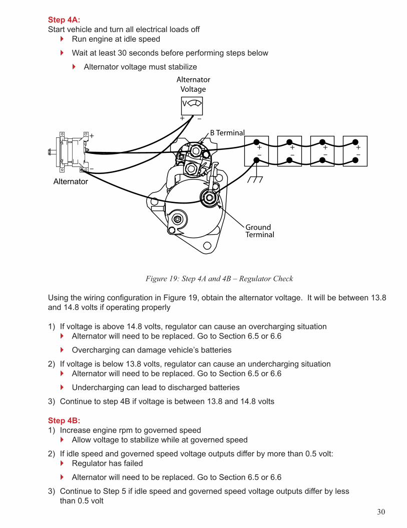
Step 4A: Start vehicle and turn all electrical loads off
Run engine at idle speed
Wait at least 30 seconds before performing steps below
Alternator voltage must stabilize
Alternator
Figure 19: Step 4A and 4B – Regulator Check
Using the wiring confi guration in Figure 19, obtain the alternator voltage. It will be between 13.8 and 14.8 volts if operating properly
1) If voltage is above 14.8 volts, regulator can cause an overcharging situationAlternator will need to be replaced. Go to Section 6.5 or 6.6
Overcharging can damage vehicle’s batteries
2) If voltage is below 13.8 volts, regulator can cause an undercharging situation Alternator will need to be replaced. Go to Section 6.5 or 6.6
Undercharging can lead to discharged batteries
3) Continue to step 4B if voltage is between 13.8 and 14.8 volts
Step 4B:1) Increase engine rpm to governed speed
Allow voltage to stabilize while at governed speed
2) If idle speed and governed speed voltage outputs differ by more than 0.5 volt: Regulator has failed
Alternator will need to be replaced. Go to Section 6.5 or 6.6
3) Continue to Step 5 if idle speed and governed speed voltage outputs differ by less than 0.5 volt
�
�
�
�
�
�
�
�
�
�

31
Step 5: Output Check with Carbon Pile Load TesterConnect load tester, voltmeter and ammeter as shown in Figure 20. Run engine at its governed rpm, and increase load through the load tester until the alternator voltage reads 13.5 volts. This causes the alternator to generate its maximum output.1) If ammeter indicates an output of at least 90% of the alternator’s rated output:
Alternator is functioning properly
Does not need to be replaced
2) If the ammeter indicates an output of less than 90% of the alternator’s rated output:Alternator has failed
Go to Section 6.5 or 6.6
Clip-OnAmmeter
Figure 20: Step 5 – Output Check w/ Carbon Pile Load Tester
6.5 PAD Mount Alternator ReplacementBy now suffi cient steps have been taken to reasonably assume that the alternator is at fault. The alternator requires replacement.
Step 1: Alternator Removal1) Disconnect vehicle’s batteries2) Remove cables connected to alternator’s B+ and B- terminals
Note cables’ location for reinstallation
3) Disconnect accessory belt from alternator’s pulleyVisually inspect belt for cracking and fraying
4) Remove four mounting bolts connecting alternator to engine5) Remove pulley from alternator using an 8 mm hex wrench and a 24 mm wrench
It will be reinstalled on the replacement alternator
Replace pulley with a new one if damaged
Step 2: Alternator Installation1) Install pulley removed from alternator in Step 1 onto new alternator
Proper torque values are listed in Appendix B
2) Connect alternator to engine using four mounting bolts removed in Step 13) Connect accessory belt to the alternator’s pulley
�
�
�
�
�
�
�
�
�

32
4) Connect positive and negative cables to alternator5) Reconnect vehicle’s batteries6) Test alternator using the steps provided in Section 5.4: Charging System Diagnosis
Congratulations! You have now successfully completed troubleshooting your vehicle’s charging system.
6.6 Hinge Mount Alternator ReplacementBy now suffi cient steps have been taken to reasonably assume that the alternator is at fault. The alternator requires replacement.
Step 1: Alternator Removal1) Disconnect vehicle’s batteries2) Remove cables connected to alternator’s B+ and B- terminals
Note location of these cables for reinstallation
3) Loosen the mounting bolts connecting the alternator to engine4) Disconnect the accessory belt from alternator’s pulley
Visually inspect belt for cracking and fraying
5) Remove mounting bolts connecting alternator to engine6) Remove pulley from alternator using an 8 mm hex wrench and 24 mm wrench
It will be reinstalled on the replacement alternator
Replace pulley with a new one if it is damaged
Step 2: Alternator Installation1) Install pulley removed from the alternator in Step 1 onto new alternator
Proper torque values are listed in Appendix B
2) Connect alternator to engine using mounting bolts removed in Step 13) Connect accessory belt to the alternator’s pulley4) Tighten accessory belt and alternator mounting bolts5) Connect positive and negative cables to the alternator6) Reconnect vehicle’s batteries7) Test alternator using steps provided in Section 5.4: Charging System Diagnosis
Congratulations! You have now successfully completed troubleshooting your vehicle’s charging system.
�
�
�
�
�

33
Charging System Diagnosis FlowchartRefer to Section 5.4: Battery System Diagnosis for detailed instructions
Step 1:Check Batteries
(See BatteryFlowchart)
OK?
Repair/ReplaceBatteries
(See BatteryFlowchart)
Step 2: Visual CheckCorrosion
Loose ConnectionsFrayed Cables
Bulges in InsulationPulley Nut Torque
OK? Repair/ReplaceBad Parts
Step 3A: MainCable Check
Step 3B:Individual Cable Check
Determine bad cableRepair/Replace
Step 4A: Regulator CheckStart Engine
All Electrical Loads OffAllow Voltage to Stabilize
Test Output
AlternatorVoltage
Step 4B: Regulator CheckIncrease to Governed RPMAllow Voltage to Stabilize
Test Output
Yes
Yes
≤0.5 volt
13.8-14.8 volts
±0.5 volt vs. Idle
BV – Battery VoltageAV – Alternator Voltage
> - is Greater Than≤ - is Less Than or Equal to
Continued on Page 34
Start
Replace & TestAlternator
Replace & TestAlternator
No
No
>0.5 voltBV-AV
Above 14.8 volts orBelow 13.8 volts
AlternatorVoltage >0.5 volt vs. Idle
�
34
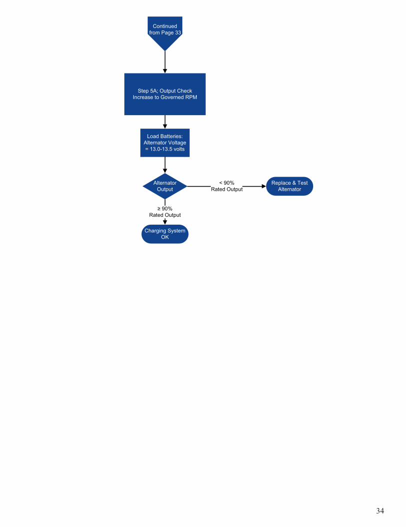
Load Batteries:Alternator Voltage= 13.0-13.5 volts
Step 5A; Output CheckIncrease to Governed RPM
≥ 90% Rated Output
Continuedfrom Page 33
Charging SystemOK
Replace & TestAlternator
AlternatorOutput
< 90%Rated Output

35
Section 7: Conclusion
We at MEAA hope that our recommended troubleshooting procedures, when followed correctly, will assist you in maintaining a heavy-duty electrical system that performs at the high levels you and your company expect. Preventive maintenance and proper use will increase the longevity and performance of your vehicle’s electronic components, resulting in less vehicle downtime. These procedures are not all inclusive and there are many situations that these procedures do not address. We rely on your experience and knowledge as a skilled maintenance technician to identify and act upon these issues.
If you require further assistance, please visit our website: www.heavyduty.meaa-mea.com
MEAA proudly stands behind every product that we manufacture. We are committed to providing you with the most reliable and durable products on the market. You can be assured of our dedication to quality and performance in every electrical component that we manufacture. This is what sets us apart.
36
Section 8: Glossary
Alternating Current (AC) - An electric current which reverses direction in a circuit at regular intervals
Alternator - An electric generator that produces alternating current (AC). Diodes within the alternator are then used to convert the AC output into DC output usable by a vehicle.
Clip-on Ammeter - Measures electric current through a cable by means of induction. Provides an output in amperes.
Ampere – Standard unit of current fl ow.
Ampere- hour – Measurement of the total energy passed through a cable during a specifi c time period.
B Terminal (Starter) – Located on the starter’s solenoid. Connected to the positive battery cable.
B+ Terminal (Alternator) – Connected to the positive battery cable.
B- Terminal (Alternator) – Connected to the negative battery cable.
Batteries – Provide power for engine cranking and electrical loads when the alternator is not generating power. Also stabilizes voltage levels in the electrical system.
Circuits Closed Circuit – Provides a continuous path for current fl ow.
Control Circuit – Transmits power to the starter’s solenoid. Includes the key switch,
remotely mounted relay (if so equipped), and associated wiring.
Open Circuit – Contains a disruption in current fl ow. This disruption is usually an air gap or an insulating material. Current is unable to fl ow in an open circuit condition.
Parallel Circuit – Closed circuit in which current fl ows through multiple paths.
Series Circuit – Closed circuit in which current fl ows through a single path.
Carbon Pile Load Tester (Load Tester) – An instrument which draws current from a battery using a variable resistance. In this manual it is used to perform voltage drop tests.
Current – Flow of electrons through a circuit.
Direct Current (DC) – An electric current fl owing in one direction only.
Electronic Tester – Combines the features of a carbon pile load tester, voltmeter and ammeter in one unit.
�
�
�
�
�
37
Field Coil – Induces a magnetic fi eld in the alternator’s rotor
Ground (Vehicle Application) – Electrical connection to the negative terminal (typically) of the vehicle’s batteries, usually through the vehicle’s frame. Used to complete an electrical circuit.
Hydrometer – An instrument used to determine the specifi c gravity of a liquid.
IMS Terminal - Located on the starter motor’s integrated magnetic switch, and is connected to the vehicle’s control circuit.
Integrated Magnetic Switch (IMS) – Starter relay that is directly mounted on the starter motor.
Magnetic Flux – A measure of the strength of a magnetic fi eld.
Ohm – Standard unit of resistance. A load with one ohm will have a voltage of 1 volt across its terminals when one ampere of current is passed through it.
Ohm’s Law – States that Voltage, Current and Amperage are interrelated. This relationship is expressed through the equation V=I x R. In this equation V=voltage, I=current fl ow and R=resistance. If two of the values are known, the equation can be manipulated to fi nd the third value.
Open Circuit Voltage – The voltage of a battery when it is not supplying current.
Pinion – Gear connected to the output shaft of a starter motor. Engages the engine’s ring gear during cranking.
Planetary Gear Reduction – Gear train which utilizes a “sun” and “planetary” gears. In a Mitsubishi Electric starter motor, this gear train is used to convert the low torque input of the armature to a high torque output at the pinion.
Rectifi er – Converts the 3-phase AC current produced by the stator into the DC current used by a vehicle’s electrical system.
Regulator – Controls the alternator’s output voltage by varying the current supplied to the fi eld coil. Mitsubishi Electric alternators have temperature compensated regulators, which increase output voltage as ambient temperature decreases. This increases the alternator’s ability to charge the batteries during cold weather.
Relay – Device that closes a set of electrical contacts when a voltage is applied. This voltage is usually applied to a coil of wire, creating a magnetic fi eld to close the electrical contacts.
Remote Mounted Relay – A relay in the control circuit of a vehicle. When this relay’s contacts are closed, it transmits power to the starter motor’s solenoid. This relay is generally mounted on a vehicle’s fi rewall or battery box.
Resistance – The opposition to current fl ow.
Ring Gear – Connected to the motor’s crankshaft by way of the fl ywheel. The starter motor’s pinion rotates the ring gear during cranking.

38
Rotor – Is rotated by a shaft connected to the alternator pulley. It is responsible for inducing voltage in the stator. The rotor’s poles create a change in magnetic fl ux in the stator.
S Terminal – Located on the starter motor’s solenoid, and is connected to the vehicle’s control circuit
Soft-Start - Allows the pinion to fully engage the ring gear before full current is applied to the starter and before the starter begins to crank the engine. A secondary circuit within the starter is utilized to slowly rotate the pinion as it is engaging the ring gear. This feature nearly eliminates pinion and ring gear wear and milling.
Solenoid – In a Mitsubishi Electric starter, this is a device that both functions as a relay and provides the mechanical force needed to extend the pinion. The relay function transmits current from the batteries to the motor portion of the starter.
Specifi c Gravity (In reference to batteries) – The density of a battery’s electrolyte relative to the density of water. This measurement is made with a Hydrometer and will determine the sulfuric acid content of the electrolyte.
Starter Motor – An electric motor for starting an engine.
State of Charge – A measure of the amount of usable power remaining in a battery.
Stator – Produces the current supplied by the alternator to the vehicle. The change in magnetic fl ux produced by the spinning rotor induces a voltage in the stator.
Temperature Compensated Regulator – Alternator regulator which increases output voltage as ambient temperature decreases. This increases the alternator’s ability to charge the batteries during cold weather.
Troubleshoot – To investigate, determine and settle or solve a problem.
Voltage – The difference in electrical “pressure” between two points.
Voltage Drop – A difference in voltage along a conductor through which current is fl owing. Loss of voltage is due to high resistance and can be caused by bad ground connections, loose connections and corrosion, improper wire sizing, broken wires, etc.
Voltmeter – Measures differences in electrical potential in volts.
39
Section 9: Legal Disclaimer
The safety of workers is the highest priority in all situations and should supersede all other considerations when you engage in troubleshooting operations.
Information in this manual is designed for use by persons with experience and training in the repair of commercial vehicle electrical systems. It is not intended to supersede or replace information contained in manufacturers’ user manuals, technical manuals, handbooks or other publications. Mitsubishi Electric Automotive America, Inc. (MEAA) is not responsible for any damage – physical, electrical or otherwise – as a result of you following the information and directions in this manual. The manual is for informational purposes only and is not intended to cover every situation or problem which you may encounter with your Mitsubishi Heavy Duty Electrical System. Some steps or directions contained in this manual may not apply depending on your particular circumstances.
THIS INFORMATION CONTAINED IN THIS MANUAL IS PROVIDED “AS IS” AND WITHOUT WARRANTIES OF ANY KIND, EXPRESS OR IMPLIED. TO THE FULLEST EXTENT PERMITTED BY LAW, MEAA DISCLAIMS ALL WARRANTIES, EXPRESS OR IMPLIED, INCLUDING BUT NOT LIMITED TO IMPLIED WARRANTIES OF MERCHANTABILITY AND FITNESS FOR A PARTICULAR PURPOSE. MEAA MAKES NO REPRESENTATIONS OR WARRANTIES REGARDING THE USE OR THE RESULTS OF THE USE OF THESE MATERIALS OR THAT DEFECTS WILL BE CORRECTED. YOU ASSUME THE ENTIRE COST OF ALL NECESSARY SERVICE, REPAIR OR CORRECTION TO THE ELECTRICAL SYSTEM.
Users of this manual should report errors or omissions, recommendations or other comments to Mitsubishi Electric Automotive America, Inc. 15603 Centennial Drive, Northville, Michigan 48168, Attention: Heavy Duty Applications Phone: (734) 453-6200; Fax: (734) 453-6212.

40
Section 10: Information Acknowledgements
Mitsubishi Electric Automotive America, Inc. would like to thank the following companies and organizations for their contributions to this manual:
Auto Meter Products Inc.
Exide Technologies
Fred Feres
Fluke Corporation
Purkey’s Electrical Consulting, Inc.
Tawas ICMS
Robert Galyen
Tom Julian
�
�
�
�
�
�
�
�

41
Appendix A: Ring Gear Wear Examples
The photos below show two different ring gears. Left: This ring gear’s teeth have not experienced excessive wear, and will provide a lowered occurrence of misengagement. Right: This ring gear’s teeth have experienced excessive wear. This ring gear has a greater chance of misengagement, and should be replaced.
Two factors affect the probability of misengagement: wear depth and wear shape. The chance of misengagement increases as wear depth increases. Sharp, uneven tooth surfaces also increase the chance of misengagement.
Examples of new ring gear teeth. Examples of worn ring gear teeth.

Dimension between the mounting surface and the end surface of ring gear
42
Appendix B: Torque Specifi cations
Starter Torque Specifi cations
B Ground IMS SW Mounting Bolts
180-264 180-264 18-22 18-22 lb.inAllModels
15-22 15-22 1.5-1.8 1.5-1.8 74-147 lb.ft20-30 20-30 2.0-2.5 2.0-2.5 100-200 N.mM12 M12 M5 M5 Size
Alternator Torque Specifi cationsRated Output
Pulley NutB+ B-
Pad Mount
70-96 31-60 lb.in145 A 5.8-8.0 2.6-5.0 72-101 lb.ft
7.8-10.8 3.5-6.8 98-137 N.m
M8 M6 8mm/24mm Size
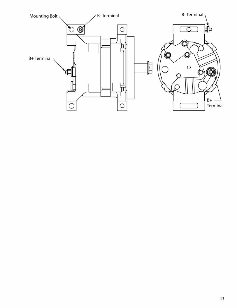
Integrated Magnetic Switch
Starter without IMSStarter with IMS
IMS Terminal
Sw TerminalB Terminal
M Terminal
B Terminal
Ground Terminal
Ground Terminal
43

44
Notes

45
Notes

46
Notes

47
Notes

48
Notes

49
Notes

50
Notes